EP3459880A1 - Système de préparation des commandes au moyen d'un bras robotisé articulé - Google Patents
Système de préparation des commandes au moyen d'un bras robotisé articulé Download PDFInfo
- Publication number
- EP3459880A1 EP3459880A1 EP17192063.0A EP17192063A EP3459880A1 EP 3459880 A1 EP3459880 A1 EP 3459880A1 EP 17192063 A EP17192063 A EP 17192063A EP 3459880 A1 EP3459880 A1 EP 3459880A1
- Authority
- EP
- European Patent Office
- Prior art keywords
- picking
- manipulator
- transport
- conveyor
- article
- Prior art date
- Legal status (The legal status is an assumption and is not a legal conclusion. Google has not performed a legal analysis and makes no representation as to the accuracy of the status listed.)
- Granted
Links
- 238000000034 method Methods 0.000 claims abstract description 19
- 238000007599 discharging Methods 0.000 claims description 2
- OKTJSMMVPCPJKN-UHFFFAOYSA-N Carbon Chemical compound [C] OKTJSMMVPCPJKN-UHFFFAOYSA-N 0.000 abstract 1
- 230000032258 transport Effects 0.000 description 94
- 238000007596 consolidation process Methods 0.000 description 3
- 230000003068 static effect Effects 0.000 description 3
- 239000000872 buffer Substances 0.000 description 2
- 230000003139 buffering effect Effects 0.000 description 2
- 239000012636 effector Substances 0.000 description 2
- 239000000463 material Substances 0.000 description 2
- 238000004590 computer program Methods 0.000 description 1
Images
Classifications
-
- B—PERFORMING OPERATIONS; TRANSPORTING
- B65—CONVEYING; PACKING; STORING; HANDLING THIN OR FILAMENTARY MATERIAL
- B65G—TRANSPORT OR STORAGE DEVICES, e.g. CONVEYORS FOR LOADING OR TIPPING, SHOP CONVEYOR SYSTEMS OR PNEUMATIC TUBE CONVEYORS
- B65G1/00—Storing articles, individually or in orderly arrangement, in warehouses or magazines
- B65G1/02—Storage devices
- B65G1/04—Storage devices mechanical
- B65G1/137—Storage devices mechanical with arrangements or automatic control means for selecting which articles are to be removed
- B65G1/1373—Storage devices mechanical with arrangements or automatic control means for selecting which articles are to be removed for fulfilling orders in warehouses
- B65G1/1378—Storage devices mechanical with arrangements or automatic control means for selecting which articles are to be removed for fulfilling orders in warehouses the orders being assembled on fixed commissioning areas remote from the storage areas
Definitions
- the present invention relates to a picking system as well as a method for picking articles from storage units of a shelf storage by means of such a picking system.
- the picking of articles can describe the removal of articles from a warehouse as well as the storage of the articles in a warehouse.
- certain subsets of the items can be put together as part of the picking process, for example to assemble and ship different items in one package.
- the articles are transported to a static order picking station.
- a corresponding article container is taken with the article to be picked from the warehouse, transported to a workstation or the static picking where then an employee can remove the desired number of articles from the container and store them, for example, in a corresponding separate order container , Subsequently, the article container is returned to the storage location.
- a picking system is to be provided, which minimizes the transport of the article container from the warehouse to a workstation. Furthermore, with the present invention, the problem of synchronization of multiple article withdrawals without additional buffers or downstream consolidation measures to be resolved.
- a method for picking goods from a rack warehouse is known, with a plurality of storage aisles and a pre-zone.
- a flow of material from storage units from a shelf of a storage lane is guided into the pre-zone, where taken in the Vorzone goods from the storage units and / or goods are introduced into the storage units of the material flow and correspondingly changed storage units are returned to a shelf of the storage lane.
- the present invention provides a solution according to the subject-matter of the independent claims.
- the present invention relates to a picking system.
- the picking system is particularly suitable for picking articles, and can be used for example in a warehouse.
- the picking system comprises a shelf storage with several shelves, each of which is set up to accommodate storage units.
- the individual shelves can preferably be arranged parallel to each other and have corresponding shelves for receiving the storage units. Between the shelves while a rack aisle is arranged, from which can be accessed on the storage units on the shelf.
- the rack aisle can be defined by the space between two adjacent shelves.
- the storage units can in turn be set up to hold one or more articles.
- the articles can be provided in, on or on the storage units.
- the storage units are designed as article containers.
- the storage units can be filled with one or more articles. For example, small parts or even larger parts, such as boxes, bottles, or individual parts can be stored in the storage units.
- Preferably, several articles of a particular type are stored in each storage unit.
- the picking system further comprises at least one conveyor system which is set up in the rack aisle arranged between the shelves.
- Each conveyor system is assigned at least one picking zone.
- the picking zone can be a three-dimensional space in which the picking according to the invention can take place.
- the picking zones are arranged on the front sides of the shelves.
- Each conveyor system is arranged to convey storage units from an adjacent shelf along the rack aisle to the respective picking zone and back.
- the conveyor system can preferably remove a storage unit from a compartment of a shelf, and convey to the picking zone and there transferred to a corresponding removal position. At a later date, the conveyor system can pick up this storage unit from the picking position and transport it back to its original rack on the rack.
- the conveyor system may remove storage units from both adjacent shelves defining the aisle alley, and convey them to the picking zone and back.
- the picking system comprises a transport system, which is set up for transporting transport units to and from each of the picking zones.
- the transport system is preferably provided separately and independently of the conveyor system.
- the transport units can be designed as a container similar to the storage units and be adapted to hold one or more articles of one or several types.
- the transport unit can be designed as a job container.
- the conveyor system and the transport system are preferably so independent of each other, so that a transport unit of the transport system preferably not directly to Conveyor system can be transferred and also a storage unit preferably can not be transferred directly from the conveyor system to the transport system.
- the transport system and the conveyor system thus preferably form closed systems.
- the picking system comprises at least one manipulator, which is set up for removing an article from the storage unit in one of the picking zones and for transferring the article into a transport unit in the same picking zone.
- a manipulator is provided in each picking zone.
- at least one such manipulator is provided on each end side of the shelves.
- a storage unit, which is located in the picking zone can thus be removed by means of the manipulator an article, and then be transferred directly into a correspondingly provided transport unit, which is for this purpose in the same picking zone.
- the storage unit can be transported via the conveyor system to this picking zone and removed from this, and the transport unit can be transported by means of the transport system to and from this picking zone.
- the manipulator operating in this picking zone is also set up to remove articles from storage units in different vertical positions in the picking zone. He can thus reach storage units, which are in higher picking positions in the picking zone.
- the picking zone can describe at least the three-dimensional space in which the manipulator can reach storage units and transport units in order to carry out the picking.
- the terms "transport” and “transport” have no different meaning, but can each describe the active movement of a storage or transport unit.
- a fully automated picking of an article can thus advantageously already take place on the shelf, namely by means of the manipulator. It is not necessary to transport the storage unit over long distances to a static picking station, since the picking directly at the interface between the on-rack conveyor system and the independent transport system.
- the conveyor system removes the corresponding storage unit from the shelf, transports it only along the shelf to the manipulator and the manipulator removes at least one article of the storage unit and transfers it to the corresponding transport unit. Then the storage unit can be transported directly back to the corresponding shelf.
- the transport unit can then be transported by means of the transport system to other picking zones and loaded with other articles.
- the transport unit or the order container must be moved over relatively long distances through the warehouse, but not a variety of storage units or article containers. Additional buffers or downstream consolidation measures are not required. Since the manipulator can access storage units in various vertical positions in the picking zone, the picking system can be used optimally in a high-bay warehouse. This can be done efficiently picking different items that are stored in different storage units in the high-bay warehouse. A complex vertical conveying of the bearing units is advantageously not necessary, since the manipulator itself can reach the provided on different vertical positions storage units in the picking zone.
- the manipulator is designed as a multi-axis articulated arm robot.
- Manipulators, and in particular robots are universally applicable handling devices that can be freely programmed in one or more degrees of freedom. By appropriate control of the respective axes, the configuration of the manipulator can be changed to move an end effector to various positions in space.
- the manipulator performs as end effector a gripper, by means of which the manipulator can remove an article from the storage unit and can transfer into a transport unit.
- the gripper can, for example, mechanically grasp the article by traction, or by suction or magnetic force allow the removal and transfer. This list is only an example and not exhaustive.
- the manipulator is movably arranged along a vertical axis.
- the manipulator can preferably be moved vertically.
- the manipulator with a vertical movement component along the height a shelf are moved.
- the system comprises a linear axis arranged to move the manipulator along the vertical axis.
- the vertical axis preferably extends along the shelf height.
- the actuator does not have to be aligned purely vertically, but must allow movement with a vertical component.
- the manipulator can be used to access the storage units transported to the picking zone directly in the various levels. Also, by moving vertically, such as over the vertical axis, the manipulator can easily access bearing units located at various vertical positions in the picking zone.
- the transport unit is vertically movable in the picking zone, and in particular preferably together with the manipulator.
- the transport unit can also be moved to an optimal vertical position, in order then to be loaded by means of the manipulator.
- the transport unit can be positioned in a stationary parking position in the picking zone, and be filled in this by the manipulator.
- the system comprises a carriage to which the manipulator is attached, and wherein the carriage is arranged to temporarily hold a transport unit.
- the carriage can thereby move vertically, and thus move the manipulator vertically.
- the transport unit can be attached to the carriage, for example by means of a click mechanism or by means of a hook, and moved vertically together with the manipulator.
- the carriage may also include a corresponding recess or else a table or a platform on which the transport unit can be stored for vertical movement.
- the moving together by the carriage transport unit is preferably within reach of the manipulator, so that the manipulator can transfer articles in the co-moving transport unit.
- a transport unit can be moved together with the manipulator to a storage unit in an elevated position, and after the manipulator has removed an article from the storage unit, the article can the return way down to the transport system already be handed over while driving in mitbewegte transport unit.
- this embodiment also enables efficient loading of a transport unit with several articles from one or more storage units in a single order picking zone, since the manipulator does not have to move to the transport unit to transfer an article. This is moved and thus remains advantageously within reach of the manipulator.
- the shelves comprise a plurality of levels, the conveyor system being arranged to horizontally convey storage units along the planes.
- a removal position is provided, in which the storage units can be brought by means of the conveyor system.
- the removal positions are set up to receive a storage unit, and the conveyor system is set up for positioning a storage unit in one of the removal positions.
- the preferably vertically movable manipulator can access each of these removal positions on the multiple levels.
- the conveyor system comprises a plurality of conveying devices, in particular preferably each with a conveyor belt.
- the conveyor system comprises one or more conveyor carriages. These can preferably pick up and move the storage units.
- the conveyor carriages can be moved by means of a conveyor belt, a conveyor drive or by self-propulsion.
- one conveying device is disposed on each level of the shelves, and the conveying devices are preferably arranged independently of one another for horizontally conveying bearing units along the respective planes.
- a storage unit can be transported to the picking zone, while on another level a storage unit of the Picking zone can be transported back to the storage space on the shelf. This increases the flexibility and speed of the picking, as several storage units can be fed independently of the manipulator for picking.
- two conveyor systems of adjacent rack aisles are assigned to a common picking zone.
- a manipulator in the picking zone can be provided with a large number of storage units for order picking, so that the utilization of the manipulator is increased.
- Each conveyor system preferably has two picking zones, each with at least one manipulator, which can be arranged adjacent to the end faces of adjacent shelves. The conveyor system can thus advantageously take removal positions of these two picking zones, whereby the flexibility and efficiency of the system is further increased.
- the transport system comprises a transport device with preferably a conveyor belt, wherein the transport device preferably connects a plurality of picking zones.
- the transport system may include a belt conveyor and / or a roller conveyor.
- the transport system is set up for discharging a transport unit into the picking zones, so that the rejected transport unit in the picking zone can be loaded with articles without disturbing the flow of the transport system.
- a discharged transport unit can remain in a pick-up position and be loaded without the transport system itself having to stand still.
- the transport unit can be introduced from the picking zone back into the transport system, for. to be transported to another picking zone.
- the transport system or the conveyor belt can run, for example, along the end faces of the shelves, with a main transport direction, which is perpendicular to a main transport direction of the conveyor system. This allows a space-saving design.
- the present invention further relates to the use of a picking system for picking as described above. Furthermore, the invention relates to a Method for picking articles from storage units of a racking warehouse by means of a picking system as described above. The method comprises the following steps:
- the process does not necessarily have to run in this order.
- the removal of the article may already be effected by means of the manipulator, for example, before the transport unit has been transported to the picking zone.
- the carriage of the storage units to the picking zone is such that there are no waiting times, and the manipulator can start immediately with the removal of the article.
- the process can be carried out simultaneously for several orders, so that a high throughput with simultaneously good time decoupling takes place between storage unit transport and transport unit transport.
- the conveying of the storage units by means of the conveyor system is a horizontal conveying
- the method preferably further comprises, before and / or after removal of the article, a vertical movement of the manipulator, wherein the vertical movement of the manipulator, in particular preferably together with a vertical movement the transport unit takes place in the picking zone.
- the transfer of the article into the transport unit can take place during the vertical movement of the manipulator.
- the removal of the article takes place before completion of transporting the transport unit to the corresponding picking zone. This increases the speed as waiting times are avoided.
- the time between the completion of transporting the transport unit to the picking zone and the beginning of the transfer of the article in the transport unit is less than 2 seconds, preferably less than 1 Second, more preferably less than 0.5 second, and most preferably less than 0.2 second. Consequently, there is a coordination of the movement of the individual elements, so that no or only small waiting times for the transport units in the picking zone arise. A buffering of the transport units is thereby advantageously avoided.
- the picking system according to the invention is preferably equipped with a corresponding control, which can be implemented centrally or decentrally and preferably controls the picking or the method described above.
- the controller can be connected or linked to a database in which the storage bins of the individual storage units are stored.
- the invention also encompasses a computer program with instructions for performing the above-mentioned functions and method steps when executed on a corresponding computer.
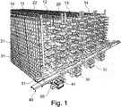
- FIG. 1 a picking system is shown, which comprises a shelf storage with multiple shelves 10, 1,12, 3, 4.
- the front shelf 10 and rear shelf 14 are shown as a sectional view.
- Each shelf 10, 1,12, 3, 4 has 18 levels, in which article container or storage units 50 can be added.
- On the shelves 10, 1,12, 3, 4 can be accessed on both sides, wherein a plurality of storage units 50 are arranged one behind the other in a shelf space.
- the shelves 10, 1,12,13,14 are arranged parallel to each other, and each define a rack aisle between them.
- Conveyor systems 30 are provided in the rack aisles, with conveyors on each shelf level.
- the bearing units 50 can be removed from the shelves 10, 11, 12, 3, 4 and transported to the respective end faces of the shelves 10, 1.12, 3, 4 or to the front side of the racking.
- the storage units 50 can be stored in removal positions 31, which are present on each shelf level on both sides of the conveying devices 30.
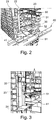
- FIG. 2 is a closer view of the order picking system FIG. 1 shown.
- the conveyor system comprises conveying carriages 32, which can be moved horizontally on each shelf level.
- the conveyor carriage 32 makes it possible to transport individual storage units 50 along a shelf level.
- the carriages are arranged for loading and unloading on both sides so that they can receive storage units 50 from both adjacent shelves and can also serve two removal positions.
- a transport system 40 is shown, by means of which transport units 51 can be transported along the end face of the rack storage.
- the transport system allows a discharge of individual transport units 51 to corresponding receiving positions 41, in which the transport units can receive one or more articles.
- manipulators 20 are provided at the end faces of the shelves 10, 11, 12, 13, 14 in the embodiment shown in each case.
- the manipulators 20 are arranged vertically by means of a carriage 22 on a vertical axis 21 so that they can be moved over the entire height of the rack.
- a manipulator 20 can thus, for example, move upwards and remove an article from a storage unit 50 in a higher removal position 31.
- the manipulator 30 can be moved down to transfer the removed article into a provided transport unit 51.
- a complex vertical transport of the storage units 51 is not required.
- the picking zone can be understood as a three-dimensional space that includes the plurality of removal positions 31 and receiving positions 41, which can reach a manipulator 30 or a pair of manipulators on the front side of a shelf 10, 11, 12, 13, 14, also using the vertical axis 21 in order to remove and transfer articles according to the invention.
- FIG. 3 a further embodiment of a picking system is shown, which, for example, in the picking system of FIG. 1 can be implemented.
- a larger-sized carriage 23 is used here by means of which the manipulator 20 can be moved vertically.
- a platform or table 24 is provided, which can receive a transport unit 51.
- the transport unit 51 can be moved from the corresponding receiving position 41 onto the table 24.
- a transport unit 51 can advantageously be brought by means of the table 24 in the vicinity of the removal position 31. This is particularly advantageous for orders with multiple order picking from the same article.
- each storage level removal positions are provided, on which by means of the conveyor system, the storage units can be made so that from the storage units in each storage level items can be removed. This process can take place simultaneously in all levels of the shelf.
- Two removal positions are provided on both sides of the conveyor system per level.
- two manipulators adjacent shelves can be operated.
- the removal takes place in the illustrated embodiments by a on a vertical axis mounted articulated robot, which has access to all shelf levels.
- one or more transfer areas or receiving positions are arranged, in which the transport units are transported to receive the articles.
- these are connected directly to the transport system in order to supply the transfer areas or pick-up positions with transport units to be loaded and to transport ready-filled transport units.
- the picking system is implemented in a storage system.
- several of the shelves are arranged side by side, and by means of the transport system, the transport units can be transported one after the other to the corresponding shelves.
- the picking system or method according to the invention can also be used or implemented in other storage systems.
Landscapes
- Engineering & Computer Science (AREA)
- Mechanical Engineering (AREA)
- Warehouses Or Storage Devices (AREA)
Priority Applications (1)
| Application Number | Priority Date | Filing Date | Title |
|---|---|---|---|
| EP17192063.0A EP3459880B1 (fr) | 2017-09-20 | 2017-09-20 | Système de préparation des commandes au moyen d'un bras robotisé articulé |
Applications Claiming Priority (1)
| Application Number | Priority Date | Filing Date | Title |
|---|---|---|---|
| EP17192063.0A EP3459880B1 (fr) | 2017-09-20 | 2017-09-20 | Système de préparation des commandes au moyen d'un bras robotisé articulé |
Publications (2)
| Publication Number | Publication Date |
|---|---|
| EP3459880A1 true EP3459880A1 (fr) | 2019-03-27 |
| EP3459880B1 EP3459880B1 (fr) | 2022-06-22 |
Family
ID=59923300
Family Applications (1)
| Application Number | Title | Priority Date | Filing Date |
|---|---|---|---|
| EP17192063.0A Active EP3459880B1 (fr) | 2017-09-20 | 2017-09-20 | Système de préparation des commandes au moyen d'un bras robotisé articulé |
Country Status (1)
| Country | Link |
|---|---|
| EP (1) | EP3459880B1 (fr) |
Cited By (3)
| Publication number | Priority date | Publication date | Assignee | Title |
|---|---|---|---|---|
| US11034532B2 (en) | 2018-05-02 | 2021-06-15 | Dematic Gmbh | Picking device for picking from a storage container into an order container, and corresponding method |
| CN114728746A (zh) * | 2019-12-05 | 2022-07-08 | 株式会社日立产业机器 | 管理系统和物品出入库管理方法 |
| DE102021132413B3 (de) | 2021-12-09 | 2023-05-11 | Ssi Schäfer Automation Gmbh (At) | Kommissionier-Shuttle und Verfahren zum Kommissionieren innerhalb einer Shuttle-Regalgasse |
Citations (10)
| Publication number | Priority date | Publication date | Assignee | Title |
|---|---|---|---|---|
| JPH0577909A (ja) * | 1991-09-20 | 1993-03-30 | Toshiba Corp | 倉庫の搬出入装置 |
| JPH06115632A (ja) * | 1992-09-30 | 1994-04-26 | Sumitomo Heavy Ind Ltd | 自動倉庫システム |
| WO2008091733A2 (fr) * | 2007-01-25 | 2008-07-31 | Bastian Material Handling, Llc | Module de prélèvement automatisé en trois dimensions |
| US20110238207A1 (en) * | 2010-03-24 | 2011-09-29 | Bastian Ii William A | Robotic automated storage and retrieval system mixed pallet build system |
| WO2014166650A1 (fr) * | 2013-04-09 | 2014-10-16 | Knapp Ag | Système de stockage et de préparation de commandes servant à l'identification et à la préparation de commandes entièrement automatisées d'articles |
| WO2015118171A1 (fr) * | 2014-02-10 | 2015-08-13 | Ocado Innovation Limited | Installation de stockage intermédiaire pour poste de préparation de commandes |
| EP2923971A1 (fr) * | 2014-03-28 | 2015-09-30 | Vanderlande Industries B.V. | Système de collection de produits et son procédé d'utilisation |
| US20160236865A1 (en) * | 2015-02-16 | 2016-08-18 | David Altemir | Automated Warehouse Storage and Retrieval System |
| WO2016196815A1 (fr) * | 2015-06-02 | 2016-12-08 | Alert Corporation | Système de stockage et de récupération |
| EP3112295A1 (fr) * | 2015-06-29 | 2017-01-04 | Stichting Sangria | Système et procédé de stockage d'objets |
-
2017
- 2017-09-20 EP EP17192063.0A patent/EP3459880B1/fr active Active
Patent Citations (10)
| Publication number | Priority date | Publication date | Assignee | Title |
|---|---|---|---|---|
| JPH0577909A (ja) * | 1991-09-20 | 1993-03-30 | Toshiba Corp | 倉庫の搬出入装置 |
| JPH06115632A (ja) * | 1992-09-30 | 1994-04-26 | Sumitomo Heavy Ind Ltd | 自動倉庫システム |
| WO2008091733A2 (fr) * | 2007-01-25 | 2008-07-31 | Bastian Material Handling, Llc | Module de prélèvement automatisé en trois dimensions |
| US20110238207A1 (en) * | 2010-03-24 | 2011-09-29 | Bastian Ii William A | Robotic automated storage and retrieval system mixed pallet build system |
| WO2014166650A1 (fr) * | 2013-04-09 | 2014-10-16 | Knapp Ag | Système de stockage et de préparation de commandes servant à l'identification et à la préparation de commandes entièrement automatisées d'articles |
| WO2015118171A1 (fr) * | 2014-02-10 | 2015-08-13 | Ocado Innovation Limited | Installation de stockage intermédiaire pour poste de préparation de commandes |
| EP2923971A1 (fr) * | 2014-03-28 | 2015-09-30 | Vanderlande Industries B.V. | Système de collection de produits et son procédé d'utilisation |
| US20160236865A1 (en) * | 2015-02-16 | 2016-08-18 | David Altemir | Automated Warehouse Storage and Retrieval System |
| WO2016196815A1 (fr) * | 2015-06-02 | 2016-12-08 | Alert Corporation | Système de stockage et de récupération |
| EP3112295A1 (fr) * | 2015-06-29 | 2017-01-04 | Stichting Sangria | Système et procédé de stockage d'objets |
Cited By (5)
| Publication number | Priority date | Publication date | Assignee | Title |
|---|---|---|---|---|
| US11034532B2 (en) | 2018-05-02 | 2021-06-15 | Dematic Gmbh | Picking device for picking from a storage container into an order container, and corresponding method |
| CN114728746A (zh) * | 2019-12-05 | 2022-07-08 | 株式会社日立产业机器 | 管理系统和物品出入库管理方法 |
| CN114728746B (zh) * | 2019-12-05 | 2024-03-08 | 株式会社日立产业机器 | 管理系统和物品出入库管理方法 |
| DE102021132413B3 (de) | 2021-12-09 | 2023-05-11 | Ssi Schäfer Automation Gmbh (At) | Kommissionier-Shuttle und Verfahren zum Kommissionieren innerhalb einer Shuttle-Regalgasse |
| WO2023104420A1 (fr) | 2021-12-09 | 2023-06-15 | Ssi Schäfer Automation Gmbh (At) | Navette de prélèvement et procédé de prélèvement à l'intérieur d'une allée de rayonnages pour navettes |
Also Published As
| Publication number | Publication date |
|---|---|
| EP3459880B1 (fr) | 2022-06-22 |
Similar Documents
| Publication | Publication Date | Title |
|---|---|---|
| EP3330200B1 (fr) | Procédé de stockage et de distribution d'objets ainsi que système de stockage permettant la mise en uvre dudit procédé | |
| AT518818B1 (de) | Verfahren zum Kommissionieren von Artikeln und Kommissionierstation | |
| EP2794434B1 (fr) | Poste de préparation des commandes et procédé de préparation des marchandises commandées | |
| EP2315714B1 (fr) | Dispositif entièrement automatique de préparation d'articles dans des contenants de commandes | |
| EP2139793B1 (fr) | Système de préparation de commandes automatisé à fonction de tri intégrée et procédé de fonctionnement associé | |
| EP1452462B1 (fr) | Système et procédé pour la préparation de commandes d'articles stockés dans des conteneurs | |
| DE102011106677B4 (de) | System und Verfahren zum Ein- und Auslagern eines Lagerguts in ein und aus einem Regal | |
| EP3762319B1 (fr) | Station de préparation de commandes et procédé destiné à préparer automatiquement des commandes de marchandises | |
| WO2013090970A2 (fr) | Système de stockage sur rayonnages et son procédé de fonctionnement | |
| AT511867A1 (de) | Kommissionierstation und verfahren zum kommissionieren von artikeln aus ladehilfsmitteln | |
| DE102009032406A1 (de) | Regallagersystem und Verfahren zum Betreiben eines Regallagersystems | |
| EP2753558B1 (fr) | Poste de préparation de commande et méthode de préparation de commande d'articles avec aide au chargement | |
| WO2018024311A1 (fr) | Système de préparation de commandes | |
| EP2611718A1 (fr) | Convoyeur de positionnement, système de stockage et procédé de reprise de charges isolées sur un convoyeur | |
| EP3459880B1 (fr) | Système de préparation des commandes au moyen d'un bras robotisé articulé | |
| AT511860A2 (de) | Kommissionierstation und verfahren zum bereitstellen von ladehilfsmitteln | |
| DE19712839A1 (de) | Kommissionierverfahren, Kommissionieranlage zur Durchführung des Verfahrens sowie Sortierpuffer hierfür | |
| EP3459879A1 (fr) | Système de stockage robotisé | |
| EP1354828B1 (fr) | Dispositif de stockage et déstockage d'objets | |
| EP3592669B1 (fr) | Procédé pour extraire des marchandises se trouvant dans un stock pour exécuter une commande | |
| EP1988038B1 (fr) | Procédé destiné à déposer et prendre des pièces sur une surface de travail | |
| DE102021132413B3 (de) | Kommissionier-Shuttle und Verfahren zum Kommissionieren innerhalb einer Shuttle-Regalgasse | |
| DE102018108150B4 (de) | Verfahren zur Handhabung von Kleinladungsträgern in Produktionsprozessen sowie modulares System zur Handhabung von Kleinladungsträgern in Produktionsprozessen | |
| EP4067266A1 (fr) | Poste de travail de préparation de commande et procédé de préparation de commande sur un poste de travail de préparation de commande |
Legal Events
| Date | Code | Title | Description |
|---|---|---|---|
| PUAI | Public reference made under article 153(3) epc to a published international application that has entered the european phase |
Free format text: ORIGINAL CODE: 0009012 |
|
| STAA | Information on the status of an ep patent application or granted ep patent |
Free format text: STATUS: THE APPLICATION HAS BEEN PUBLISHED |
|
| AK | Designated contracting states |
Kind code of ref document: A1 Designated state(s): AL AT BE BG CH CY CZ DE DK EE ES FI FR GB GR HR HU IE IS IT LI LT LU LV MC MK MT NL NO PL PT RO RS SE SI SK SM TR |
|
| AX | Request for extension of the european patent |
Extension state: BA ME |
|
| STAA | Information on the status of an ep patent application or granted ep patent |
Free format text: STATUS: REQUEST FOR EXAMINATION WAS MADE |
|
| 17P | Request for examination filed |
Effective date: 20190926 |
|
| RBV | Designated contracting states (corrected) |
Designated state(s): AL AT BE BG CH CY CZ DE DK EE ES FI FR GB GR HR HU IE IS IT LI LT LU LV MC MK MT NL NO PL PT RO RS SE SI SK SM TR |
|
| GRAP | Despatch of communication of intention to grant a patent |
Free format text: ORIGINAL CODE: EPIDOSNIGR1 |
|
| STAA | Information on the status of an ep patent application or granted ep patent |
Free format text: STATUS: GRANT OF PATENT IS INTENDED |
|
| RIC1 | Information provided on ipc code assigned before grant |
Ipc: B65G 1/137 20060101AFI20220201BHEP |
|
| INTG | Intention to grant announced |
Effective date: 20220217 |
|
| GRAS | Grant fee paid |
Free format text: ORIGINAL CODE: EPIDOSNIGR3 |
|
| GRAA | (expected) grant |
Free format text: ORIGINAL CODE: 0009210 |
|
| STAA | Information on the status of an ep patent application or granted ep patent |
Free format text: STATUS: THE PATENT HAS BEEN GRANTED |
|
| AK | Designated contracting states |
Kind code of ref document: B1 Designated state(s): AL AT BE BG CH CY CZ DE DK EE ES FI FR GB GR HR HU IE IS IT LI LT LU LV MC MK MT NL NO PL PT RO RS SE SI SK SM TR |
|
| REG | Reference to a national code |
Ref country code: GB Ref legal event code: FG4D Free format text: NOT ENGLISH |
|
| REG | Reference to a national code |
Ref country code: CH Ref legal event code: EP |
|
| REG | Reference to a national code |
Ref country code: DE Ref legal event code: R096 Ref document number: 502017013351 Country of ref document: DE |
|
| REG | Reference to a national code |
Ref country code: AT Ref legal event code: REF Ref document number: 1499659 Country of ref document: AT Kind code of ref document: T Effective date: 20220715 |
|
| REG | Reference to a national code |
Ref country code: IE Ref legal event code: FG4D Free format text: LANGUAGE OF EP DOCUMENT: GERMAN |
|
| REG | Reference to a national code |
Ref country code: LT Ref legal event code: MG9D |
|
| REG | Reference to a national code |
Ref country code: NL Ref legal event code: MP Effective date: 20220622 |
|
| PG25 | Lapsed in a contracting state [announced via postgrant information from national office to epo] |
Ref country code: SE Free format text: LAPSE BECAUSE OF FAILURE TO SUBMIT A TRANSLATION OF THE DESCRIPTION OR TO PAY THE FEE WITHIN THE PRESCRIBED TIME-LIMIT Effective date: 20220622 Ref country code: NO Free format text: LAPSE BECAUSE OF FAILURE TO SUBMIT A TRANSLATION OF THE DESCRIPTION OR TO PAY THE FEE WITHIN THE PRESCRIBED TIME-LIMIT Effective date: 20220922 Ref country code: LT Free format text: LAPSE BECAUSE OF FAILURE TO SUBMIT A TRANSLATION OF THE DESCRIPTION OR TO PAY THE FEE WITHIN THE PRESCRIBED TIME-LIMIT Effective date: 20220622 Ref country code: HR Free format text: LAPSE BECAUSE OF FAILURE TO SUBMIT A TRANSLATION OF THE DESCRIPTION OR TO PAY THE FEE WITHIN THE PRESCRIBED TIME-LIMIT Effective date: 20220622 Ref country code: GR Free format text: LAPSE BECAUSE OF FAILURE TO SUBMIT A TRANSLATION OF THE DESCRIPTION OR TO PAY THE FEE WITHIN THE PRESCRIBED TIME-LIMIT Effective date: 20220923 Ref country code: FI Free format text: LAPSE BECAUSE OF FAILURE TO SUBMIT A TRANSLATION OF THE DESCRIPTION OR TO PAY THE FEE WITHIN THE PRESCRIBED TIME-LIMIT Effective date: 20220622 Ref country code: BG Free format text: LAPSE BECAUSE OF FAILURE TO SUBMIT A TRANSLATION OF THE DESCRIPTION OR TO PAY THE FEE WITHIN THE PRESCRIBED TIME-LIMIT Effective date: 20220922 |
|
| PG25 | Lapsed in a contracting state [announced via postgrant information from national office to epo] |
Ref country code: RS Free format text: LAPSE BECAUSE OF FAILURE TO SUBMIT A TRANSLATION OF THE DESCRIPTION OR TO PAY THE FEE WITHIN THE PRESCRIBED TIME-LIMIT Effective date: 20220622 Ref country code: LV Free format text: LAPSE BECAUSE OF FAILURE TO SUBMIT A TRANSLATION OF THE DESCRIPTION OR TO PAY THE FEE WITHIN THE PRESCRIBED TIME-LIMIT Effective date: 20220622 |
|
| PG25 | Lapsed in a contracting state [announced via postgrant information from national office to epo] |
Ref country code: NL Free format text: LAPSE BECAUSE OF FAILURE TO SUBMIT A TRANSLATION OF THE DESCRIPTION OR TO PAY THE FEE WITHIN THE PRESCRIBED TIME-LIMIT Effective date: 20220622 |
|
| PG25 | Lapsed in a contracting state [announced via postgrant information from national office to epo] |
Ref country code: SM Free format text: LAPSE BECAUSE OF FAILURE TO SUBMIT A TRANSLATION OF THE DESCRIPTION OR TO PAY THE FEE WITHIN THE PRESCRIBED TIME-LIMIT Effective date: 20220622 Ref country code: SK Free format text: LAPSE BECAUSE OF FAILURE TO SUBMIT A TRANSLATION OF THE DESCRIPTION OR TO PAY THE FEE WITHIN THE PRESCRIBED TIME-LIMIT Effective date: 20220622 Ref country code: RO Free format text: LAPSE BECAUSE OF FAILURE TO SUBMIT A TRANSLATION OF THE DESCRIPTION OR TO PAY THE FEE WITHIN THE PRESCRIBED TIME-LIMIT Effective date: 20220622 Ref country code: PT Free format text: LAPSE BECAUSE OF FAILURE TO SUBMIT A TRANSLATION OF THE DESCRIPTION OR TO PAY THE FEE WITHIN THE PRESCRIBED TIME-LIMIT Effective date: 20221024 Ref country code: ES Free format text: LAPSE BECAUSE OF FAILURE TO SUBMIT A TRANSLATION OF THE DESCRIPTION OR TO PAY THE FEE WITHIN THE PRESCRIBED TIME-LIMIT Effective date: 20220622 Ref country code: EE Free format text: LAPSE BECAUSE OF FAILURE TO SUBMIT A TRANSLATION OF THE DESCRIPTION OR TO PAY THE FEE WITHIN THE PRESCRIBED TIME-LIMIT Effective date: 20220622 Ref country code: CZ Free format text: LAPSE BECAUSE OF FAILURE TO SUBMIT A TRANSLATION OF THE DESCRIPTION OR TO PAY THE FEE WITHIN THE PRESCRIBED TIME-LIMIT Effective date: 20220622 |
|
| PG25 | Lapsed in a contracting state [announced via postgrant information from national office to epo] |
Ref country code: PL Free format text: LAPSE BECAUSE OF FAILURE TO SUBMIT A TRANSLATION OF THE DESCRIPTION OR TO PAY THE FEE WITHIN THE PRESCRIBED TIME-LIMIT Effective date: 20220622 Ref country code: IS Free format text: LAPSE BECAUSE OF FAILURE TO SUBMIT A TRANSLATION OF THE DESCRIPTION OR TO PAY THE FEE WITHIN THE PRESCRIBED TIME-LIMIT Effective date: 20221022 |
|
| REG | Reference to a national code |
Ref country code: DE Ref legal event code: R097 Ref document number: 502017013351 Country of ref document: DE |
|
| PG25 | Lapsed in a contracting state [announced via postgrant information from national office to epo] |
Ref country code: AL Free format text: LAPSE BECAUSE OF FAILURE TO SUBMIT A TRANSLATION OF THE DESCRIPTION OR TO PAY THE FEE WITHIN THE PRESCRIBED TIME-LIMIT Effective date: 20220622 |
|
| PG25 | Lapsed in a contracting state [announced via postgrant information from national office to epo] |
Ref country code: MC Free format text: LAPSE BECAUSE OF FAILURE TO SUBMIT A TRANSLATION OF THE DESCRIPTION OR TO PAY THE FEE WITHIN THE PRESCRIBED TIME-LIMIT Effective date: 20220622 Ref country code: DK Free format text: LAPSE BECAUSE OF FAILURE TO SUBMIT A TRANSLATION OF THE DESCRIPTION OR TO PAY THE FEE WITHIN THE PRESCRIBED TIME-LIMIT Effective date: 20220622 |
|
| PLBE | No opposition filed within time limit |
Free format text: ORIGINAL CODE: 0009261 |
|
| STAA | Information on the status of an ep patent application or granted ep patent |
Free format text: STATUS: NO OPPOSITION FILED WITHIN TIME LIMIT |
|
| REG | Reference to a national code |
Ref country code: BE Ref legal event code: MM Effective date: 20220930 |
|
| 26N | No opposition filed |
Effective date: 20230323 |
|
| PG25 | Lapsed in a contracting state [announced via postgrant information from national office to epo] |
Ref country code: LU Free format text: LAPSE BECAUSE OF NON-PAYMENT OF DUE FEES Effective date: 20220920 |
|
| P01 | Opt-out of the competence of the unified patent court (upc) registered |
Effective date: 20230528 |
|
| PG25 | Lapsed in a contracting state [announced via postgrant information from national office to epo] |
Ref country code: IE Free format text: LAPSE BECAUSE OF NON-PAYMENT OF DUE FEES Effective date: 20220920 |
|
| PG25 | Lapsed in a contracting state [announced via postgrant information from national office to epo] |
Ref country code: SI Free format text: LAPSE BECAUSE OF FAILURE TO SUBMIT A TRANSLATION OF THE DESCRIPTION OR TO PAY THE FEE WITHIN THE PRESCRIBED TIME-LIMIT Effective date: 20220622 |
|
| PG25 | Lapsed in a contracting state [announced via postgrant information from national office to epo] |
Ref country code: BE Free format text: LAPSE BECAUSE OF NON-PAYMENT OF DUE FEES Effective date: 20220930 |
|
| PGFP | Annual fee paid to national office [announced via postgrant information from national office to epo] |
Ref country code: GB Payment date: 20230727 Year of fee payment: 7 Ref country code: AT Payment date: 20230825 Year of fee payment: 7 |
|
| PGFP | Annual fee paid to national office [announced via postgrant information from national office to epo] |
Ref country code: FR Payment date: 20230808 Year of fee payment: 7 Ref country code: DE Payment date: 20230726 Year of fee payment: 7 |
|
| PG25 | Lapsed in a contracting state [announced via postgrant information from national office to epo] |
Ref country code: IT Free format text: LAPSE BECAUSE OF FAILURE TO SUBMIT A TRANSLATION OF THE DESCRIPTION OR TO PAY THE FEE WITHIN THE PRESCRIBED TIME-LIMIT Effective date: 20220622 |
|
| PGFP | Annual fee paid to national office [announced via postgrant information from national office to epo] |
Ref country code: CH Payment date: 20231001 Year of fee payment: 7 |
|
| PG25 | Lapsed in a contracting state [announced via postgrant information from national office to epo] |
Ref country code: HU Free format text: LAPSE BECAUSE OF FAILURE TO SUBMIT A TRANSLATION OF THE DESCRIPTION OR TO PAY THE FEE WITHIN THE PRESCRIBED TIME-LIMIT; INVALID AB INITIO Effective date: 20170920 |
|
| PG25 | Lapsed in a contracting state [announced via postgrant information from national office to epo] |
Ref country code: CY Free format text: LAPSE BECAUSE OF FAILURE TO SUBMIT A TRANSLATION OF THE DESCRIPTION OR TO PAY THE FEE WITHIN THE PRESCRIBED TIME-LIMIT Effective date: 20220622 |