EP3459701B1 - Schneidvorrichtung zum zerkleinern von pastösen stoffen - Google Patents
Schneidvorrichtung zum zerkleinern von pastösen stoffen Download PDFInfo
- Publication number
- EP3459701B1 EP3459701B1 EP18191208.0A EP18191208A EP3459701B1 EP 3459701 B1 EP3459701 B1 EP 3459701B1 EP 18191208 A EP18191208 A EP 18191208A EP 3459701 B1 EP3459701 B1 EP 3459701B1
- Authority
- EP
- European Patent Office
- Prior art keywords
- section
- cutting device
- cutting
- flow cross
- outlet
- Prior art date
- Legal status (The legal status is an assumption and is not a legal conclusion. Google has not performed a legal analysis and makes no representation as to the accuracy of the status listed.)
- Active
Links
- 238000005520 cutting process Methods 0.000 title claims description 156
- 235000011837 pasties Nutrition 0.000 title claims description 75
- 239000000463 material Substances 0.000 title description 67
- 239000000126 substance Substances 0.000 claims description 65
- 238000012545 processing Methods 0.000 claims description 14
- 238000001704 evaporation Methods 0.000 claims description 3
- 230000008020 evaporation Effects 0.000 claims description 3
- 230000007704 transition Effects 0.000 claims description 3
- 238000001816 cooling Methods 0.000 claims description 2
- 239000012530 fluid Substances 0.000 claims description 2
- 238000009434 installation Methods 0.000 claims 8
- 239000008188 pellet Substances 0.000 description 24
- 238000000926 separation method Methods 0.000 description 15
- 238000013461 design Methods 0.000 description 9
- 238000000034 method Methods 0.000 description 8
- 238000004519 manufacturing process Methods 0.000 description 7
- 230000008859 change Effects 0.000 description 6
- 239000000835 fiber Substances 0.000 description 6
- 238000000465 moulding Methods 0.000 description 6
- 239000000047 product Substances 0.000 description 6
- 238000007373 indentation Methods 0.000 description 5
- 239000002245 particle Substances 0.000 description 5
- 239000000203 mixture Substances 0.000 description 4
- 230000008569 process Effects 0.000 description 4
- 238000011161 development Methods 0.000 description 3
- 230000018109 developmental process Effects 0.000 description 3
- 238000011068 loading method Methods 0.000 description 3
- 230000008707 rearrangement Effects 0.000 description 3
- 239000007787 solid Substances 0.000 description 3
- 238000011144 upstream manufacturing Methods 0.000 description 3
- 238000006073 displacement reaction Methods 0.000 description 2
- 238000001035 drying Methods 0.000 description 2
- 230000000694 effects Effects 0.000 description 2
- 210000004209 hair Anatomy 0.000 description 2
- 230000002452 interceptive effect Effects 0.000 description 2
- 238000007493 shaping process Methods 0.000 description 2
- 239000010802 sludge Substances 0.000 description 2
- 239000003082 abrasive agent Substances 0.000 description 1
- 230000002411 adverse Effects 0.000 description 1
- 238000005452 bending Methods 0.000 description 1
- 230000008901 benefit Effects 0.000 description 1
- 230000015572 biosynthetic process Effects 0.000 description 1
- 239000004566 building material Substances 0.000 description 1
- 238000005266 casting Methods 0.000 description 1
- 229910010293 ceramic material Inorganic materials 0.000 description 1
- 239000007795 chemical reaction product Substances 0.000 description 1
- 239000004927 clay Substances 0.000 description 1
- 239000011248 coating agent Substances 0.000 description 1
- 238000000576 coating method Methods 0.000 description 1
- 238000005056 compaction Methods 0.000 description 1
- 239000000356 contaminant Substances 0.000 description 1
- 238000011109 contamination Methods 0.000 description 1
- 230000001419 dependent effect Effects 0.000 description 1
- 238000001125 extrusion Methods 0.000 description 1
- 239000004744 fabric Substances 0.000 description 1
- 238000005243 fluidization Methods 0.000 description 1
- 235000013305 food Nutrition 0.000 description 1
- 239000012634 fragment Substances 0.000 description 1
- 238000009499 grossing Methods 0.000 description 1
- 239000013067 intermediate product Substances 0.000 description 1
- 239000007788 liquid Substances 0.000 description 1
- 238000003754 machining Methods 0.000 description 1
- 238000012423 maintenance Methods 0.000 description 1
- 238000005453 pelletization Methods 0.000 description 1
- 230000035515 penetration Effects 0.000 description 1
- 239000004033 plastic Substances 0.000 description 1
- 229920003023 plastic Polymers 0.000 description 1
- 238000003825 pressing Methods 0.000 description 1
- 230000001737 promoting effect Effects 0.000 description 1
- 238000005086 pumping Methods 0.000 description 1
- 230000009467 reduction Effects 0.000 description 1
- 239000010865 sewage Substances 0.000 description 1
- 239000010801 sewage sludge Substances 0.000 description 1
- 239000010454 slate Substances 0.000 description 1
- 239000011343 solid material Substances 0.000 description 1
- 239000004071 soot Substances 0.000 description 1
- 230000006641 stabilisation Effects 0.000 description 1
- 238000011105 stabilization Methods 0.000 description 1
- 229920001169 thermoplastic Polymers 0.000 description 1
- 239000004416 thermosoftening plastic Substances 0.000 description 1
- XLYOFNOQVPJJNP-UHFFFAOYSA-N water Substances O XLYOFNOQVPJJNP-UHFFFAOYSA-N 0.000 description 1
Images


Classifications
-
- B—PERFORMING OPERATIONS; TRANSPORTING
- B26—HAND CUTTING TOOLS; CUTTING; SEVERING
- B26D—CUTTING; DETAILS COMMON TO MACHINES FOR PERFORATING, PUNCHING, CUTTING-OUT, STAMPING-OUT OR SEVERING
- B26D1/00—Cutting through work characterised by the nature or movement of the cutting member or particular materials not otherwise provided for; Apparatus or machines therefor; Cutting members therefor
- B26D1/01—Cutting through work characterised by the nature or movement of the cutting member or particular materials not otherwise provided for; Apparatus or machines therefor; Cutting members therefor involving a cutting member which does not travel with the work
- B26D1/12—Cutting through work characterised by the nature or movement of the cutting member or particular materials not otherwise provided for; Apparatus or machines therefor; Cutting members therefor involving a cutting member which does not travel with the work having a cutting member moving about an axis
- B26D1/25—Cutting through work characterised by the nature or movement of the cutting member or particular materials not otherwise provided for; Apparatus or machines therefor; Cutting members therefor involving a cutting member which does not travel with the work having a cutting member moving about an axis with a non-circular cutting member
- B26D1/34—Cutting through work characterised by the nature or movement of the cutting member or particular materials not otherwise provided for; Apparatus or machines therefor; Cutting members therefor involving a cutting member which does not travel with the work having a cutting member moving about an axis with a non-circular cutting member moving about an axis parallel to the line of cut
- B26D1/36—Cutting through work characterised by the nature or movement of the cutting member or particular materials not otherwise provided for; Apparatus or machines therefor; Cutting members therefor involving a cutting member which does not travel with the work having a cutting member moving about an axis with a non-circular cutting member moving about an axis parallel to the line of cut and rotating continuously in one direction during cutting, e.g. mounted on a rotary cylinder
-
- B—PERFORMING OPERATIONS; TRANSPORTING
- B02—CRUSHING, PULVERISING, OR DISINTEGRATING; PREPARATORY TREATMENT OF GRAIN FOR MILLING
- B02C—CRUSHING, PULVERISING, OR DISINTEGRATING IN GENERAL; MILLING GRAIN
- B02C18/00—Disintegrating by knives or other cutting or tearing members which chop material into fragments
- B02C18/06—Disintegrating by knives or other cutting or tearing members which chop material into fragments with rotating knives
- B02C18/16—Details
- B02C18/22—Feed or discharge means
- B02C18/2225—Feed means
-
- A—HUMAN NECESSITIES
- A23—FOODS OR FOODSTUFFS; TREATMENT THEREOF, NOT COVERED BY OTHER CLASSES
- A23P—SHAPING OR WORKING OF FOODSTUFFS, NOT FULLY COVERED BY A SINGLE OTHER SUBCLASS
- A23P30/00—Shaping or working of foodstuffs characterised by the process or apparatus
- A23P30/10—Moulding
-
- B—PERFORMING OPERATIONS; TRANSPORTING
- B01—PHYSICAL OR CHEMICAL PROCESSES OR APPARATUS IN GENERAL
- B01J—CHEMICAL OR PHYSICAL PROCESSES, e.g. CATALYSIS OR COLLOID CHEMISTRY; THEIR RELEVANT APPARATUS
- B01J2/00—Processes or devices for granulating materials, e.g. fertilisers in general; Rendering particulate materials free flowing in general, e.g. making them hydrophobic
- B01J2/20—Processes or devices for granulating materials, e.g. fertilisers in general; Rendering particulate materials free flowing in general, e.g. making them hydrophobic by expressing the material, e.g. through sieves and fragmenting the extruded length
-
- B—PERFORMING OPERATIONS; TRANSPORTING
- B02—CRUSHING, PULVERISING, OR DISINTEGRATING; PREPARATORY TREATMENT OF GRAIN FOR MILLING
- B02C—CRUSHING, PULVERISING, OR DISINTEGRATING IN GENERAL; MILLING GRAIN
- B02C18/00—Disintegrating by knives or other cutting or tearing members which chop material into fragments
- B02C18/06—Disintegrating by knives or other cutting or tearing members which chop material into fragments with rotating knives
- B02C18/14—Disintegrating by knives or other cutting or tearing members which chop material into fragments with rotating knives within horizontal containers
-
- B—PERFORMING OPERATIONS; TRANSPORTING
- B26—HAND CUTTING TOOLS; CUTTING; SEVERING
- B26D—CUTTING; DETAILS COMMON TO MACHINES FOR PERFORATING, PUNCHING, CUTTING-OUT, STAMPING-OUT OR SEVERING
- B26D1/00—Cutting through work characterised by the nature or movement of the cutting member or particular materials not otherwise provided for; Apparatus or machines therefor; Cutting members therefor
- B26D1/01—Cutting through work characterised by the nature or movement of the cutting member or particular materials not otherwise provided for; Apparatus or machines therefor; Cutting members therefor involving a cutting member which does not travel with the work
- B26D1/12—Cutting through work characterised by the nature or movement of the cutting member or particular materials not otherwise provided for; Apparatus or machines therefor; Cutting members therefor involving a cutting member which does not travel with the work having a cutting member moving about an axis
- B26D1/25—Cutting through work characterised by the nature or movement of the cutting member or particular materials not otherwise provided for; Apparatus or machines therefor; Cutting members therefor involving a cutting member which does not travel with the work having a cutting member moving about an axis with a non-circular cutting member
- B26D1/26—Cutting through work characterised by the nature or movement of the cutting member or particular materials not otherwise provided for; Apparatus or machines therefor; Cutting members therefor involving a cutting member which does not travel with the work having a cutting member moving about an axis with a non-circular cutting member moving about an axis substantially perpendicular to the line of cut
- B26D1/28—Cutting through work characterised by the nature or movement of the cutting member or particular materials not otherwise provided for; Apparatus or machines therefor; Cutting members therefor involving a cutting member which does not travel with the work having a cutting member moving about an axis with a non-circular cutting member moving about an axis substantially perpendicular to the line of cut and rotating continuously in one direction during cutting
-
- B—PERFORMING OPERATIONS; TRANSPORTING
- B26—HAND CUTTING TOOLS; CUTTING; SEVERING
- B26D—CUTTING; DETAILS COMMON TO MACHINES FOR PERFORATING, PUNCHING, CUTTING-OUT, STAMPING-OUT OR SEVERING
- B26D7/00—Details of apparatus for cutting, cutting-out, stamping-out, punching, perforating, or severing by means other than cutting
- B26D7/06—Arrangements for feeding or delivering work of other than sheet, web, or filamentary form
- B26D7/0683—Arrangements for feeding or delivering work of other than sheet, web, or filamentary form specially adapted for elongated articles
-
- B—PERFORMING OPERATIONS; TRANSPORTING
- B29—WORKING OF PLASTICS; WORKING OF SUBSTANCES IN A PLASTIC STATE IN GENERAL
- B29B—PREPARATION OR PRETREATMENT OF THE MATERIAL TO BE SHAPED; MAKING GRANULES OR PREFORMS; RECOVERY OF PLASTICS OR OTHER CONSTITUENTS OF WASTE MATERIAL CONTAINING PLASTICS
- B29B9/00—Making granules
- B29B9/02—Making granules by dividing preformed material
- B29B9/06—Making granules by dividing preformed material in the form of filamentary material, e.g. combined with extrusion
-
- B—PERFORMING OPERATIONS; TRANSPORTING
- B29—WORKING OF PLASTICS; WORKING OF SUBSTANCES IN A PLASTIC STATE IN GENERAL
- B29C—SHAPING OR JOINING OF PLASTICS; SHAPING OF MATERIAL IN A PLASTIC STATE, NOT OTHERWISE PROVIDED FOR; AFTER-TREATMENT OF THE SHAPED PRODUCTS, e.g. REPAIRING
- B29C48/00—Extrusion moulding, i.e. expressing the moulding material through a die or nozzle which imparts the desired form; Apparatus therefor
- B29C48/001—Combinations of extrusion moulding with other shaping operations
- B29C48/0022—Combinations of extrusion moulding with other shaping operations combined with cutting
-
- B—PERFORMING OPERATIONS; TRANSPORTING
- B29—WORKING OF PLASTICS; WORKING OF SUBSTANCES IN A PLASTIC STATE IN GENERAL
- B29C—SHAPING OR JOINING OF PLASTICS; SHAPING OF MATERIAL IN A PLASTIC STATE, NOT OTHERWISE PROVIDED FOR; AFTER-TREATMENT OF THE SHAPED PRODUCTS, e.g. REPAIRING
- B29C48/00—Extrusion moulding, i.e. expressing the moulding material through a die or nozzle which imparts the desired form; Apparatus therefor
- B29C48/03—Extrusion moulding, i.e. expressing the moulding material through a die or nozzle which imparts the desired form; Apparatus therefor characterised by the shape of the extruded material at extrusion
- B29C48/04—Particle-shaped
-
- B—PERFORMING OPERATIONS; TRANSPORTING
- B29—WORKING OF PLASTICS; WORKING OF SUBSTANCES IN A PLASTIC STATE IN GENERAL
- B29C—SHAPING OR JOINING OF PLASTICS; SHAPING OF MATERIAL IN A PLASTIC STATE, NOT OTHERWISE PROVIDED FOR; AFTER-TREATMENT OF THE SHAPED PRODUCTS, e.g. REPAIRING
- B29C48/00—Extrusion moulding, i.e. expressing the moulding material through a die or nozzle which imparts the desired form; Apparatus therefor
- B29C48/03—Extrusion moulding, i.e. expressing the moulding material through a die or nozzle which imparts the desired form; Apparatus therefor characterised by the shape of the extruded material at extrusion
- B29C48/131—Curved articles
-
- B—PERFORMING OPERATIONS; TRANSPORTING
- B29—WORKING OF PLASTICS; WORKING OF SUBSTANCES IN A PLASTIC STATE IN GENERAL
- B29C—SHAPING OR JOINING OF PLASTICS; SHAPING OF MATERIAL IN A PLASTIC STATE, NOT OTHERWISE PROVIDED FOR; AFTER-TREATMENT OF THE SHAPED PRODUCTS, e.g. REPAIRING
- B29C48/00—Extrusion moulding, i.e. expressing the moulding material through a die or nozzle which imparts the desired form; Apparatus therefor
- B29C48/25—Component parts, details or accessories; Auxiliary operations
- B29C48/30—Extrusion nozzles or dies
- B29C48/3001—Extrusion nozzles or dies characterised by the material or their manufacturing process
-
- B—PERFORMING OPERATIONS; TRANSPORTING
- B29—WORKING OF PLASTICS; WORKING OF SUBSTANCES IN A PLASTIC STATE IN GENERAL
- B29C—SHAPING OR JOINING OF PLASTICS; SHAPING OF MATERIAL IN A PLASTIC STATE, NOT OTHERWISE PROVIDED FOR; AFTER-TREATMENT OF THE SHAPED PRODUCTS, e.g. REPAIRING
- B29C48/00—Extrusion moulding, i.e. expressing the moulding material through a die or nozzle which imparts the desired form; Apparatus therefor
- B29C48/25—Component parts, details or accessories; Auxiliary operations
- B29C48/30—Extrusion nozzles or dies
- B29C48/301—Extrusion nozzles or dies having reciprocating, oscillating or rotating parts
-
- B—PERFORMING OPERATIONS; TRANSPORTING
- B29—WORKING OF PLASTICS; WORKING OF SUBSTANCES IN A PLASTIC STATE IN GENERAL
- B29C—SHAPING OR JOINING OF PLASTICS; SHAPING OF MATERIAL IN A PLASTIC STATE, NOT OTHERWISE PROVIDED FOR; AFTER-TREATMENT OF THE SHAPED PRODUCTS, e.g. REPAIRING
- B29C48/00—Extrusion moulding, i.e. expressing the moulding material through a die or nozzle which imparts the desired form; Apparatus therefor
- B29C48/25—Component parts, details or accessories; Auxiliary operations
- B29C48/30—Extrusion nozzles or dies
- B29C48/32—Extrusion nozzles or dies with annular openings, e.g. for forming tubular articles
- B29C48/325—Extrusion nozzles or dies with annular openings, e.g. for forming tubular articles being adjustable, i.e. having adjustable exit sections
- B29C48/327—Extrusion nozzles or dies with annular openings, e.g. for forming tubular articles being adjustable, i.e. having adjustable exit sections with centering means
-
- B—PERFORMING OPERATIONS; TRANSPORTING
- B29—WORKING OF PLASTICS; WORKING OF SUBSTANCES IN A PLASTIC STATE IN GENERAL
- B29C—SHAPING OR JOINING OF PLASTICS; SHAPING OF MATERIAL IN A PLASTIC STATE, NOT OTHERWISE PROVIDED FOR; AFTER-TREATMENT OF THE SHAPED PRODUCTS, e.g. REPAIRING
- B29C48/00—Extrusion moulding, i.e. expressing the moulding material through a die or nozzle which imparts the desired form; Apparatus therefor
- B29C48/25—Component parts, details or accessories; Auxiliary operations
- B29C48/30—Extrusion nozzles or dies
- B29C48/32—Extrusion nozzles or dies with annular openings, e.g. for forming tubular articles
- B29C48/33—Extrusion nozzles or dies with annular openings, e.g. for forming tubular articles with parts rotatable relative to each other
-
- A—HUMAN NECESSITIES
- A23—FOODS OR FOODSTUFFS; TREATMENT THEREOF, NOT COVERED BY OTHER CLASSES
- A23V—INDEXING SCHEME RELATING TO FOODS, FOODSTUFFS OR NON-ALCOHOLIC BEVERAGES AND LACTIC OR PROPIONIC ACID BACTERIA USED IN FOODSTUFFS OR FOOD PREPARATION
- A23V2002/00—Food compositions, function of food ingredients or processes for food or foodstuffs
-
- B—PERFORMING OPERATIONS; TRANSPORTING
- B26—HAND CUTTING TOOLS; CUTTING; SEVERING
- B26D—CUTTING; DETAILS COMMON TO MACHINES FOR PERFORATING, PUNCHING, CUTTING-OUT, STAMPING-OUT OR SEVERING
- B26D1/00—Cutting through work characterised by the nature or movement of the cutting member or particular materials not otherwise provided for; Apparatus or machines therefor; Cutting members therefor
- B26D1/0006—Cutting members therefor
- B26D2001/006—Cutting members therefor the cutting blade having a special shape, e.g. a special outline, serrations
-
- B—PERFORMING OPERATIONS; TRANSPORTING
- B26—HAND CUTTING TOOLS; CUTTING; SEVERING
- B26D—CUTTING; DETAILS COMMON TO MACHINES FOR PERFORATING, PUNCHING, CUTTING-OUT, STAMPING-OUT OR SEVERING
- B26D2210/00—Machines or methods used for cutting special materials
- B26D2210/02—Machines or methods used for cutting special materials for cutting food products, e.g. food slicers
Definitions
- the invention relates to a cutting device for comminuting pasty substances with a nozzle with a nozzle housing, the at least one inlet with an inlet flow cross-section through which the pasty substance enters the nozzle, and an outlet with an outlet flow cross-section through which the pasty Substance emerges from the nozzle and has a flow channel leading from the inlet to the outlet, with a rotating cutting tool arranged at the outlet for cutting the exiting pasty substance.
- the invention also relates to a system comprising such a cutting device and a further processing device which is coupled to the cutting device.
- the invention relates in particular to a cutting device and a system for comminuting and separating, in particular, such pasty substances with fibers and / or particles that are difficult or impossible to divide.
- Such pasty substances are comminuted into pellets so that shapeless masses can be reliably separated into uniform shaped bodies.
- the shaped bodies Simultaneously with the comminution and separation, the shaped bodies, which are contaminated with fibers and foreign substances and can also be sticky on the surface, can be introduced into a surrounding fluid, for example in a vacuum or high pressure environment.
- the substance is pressed through a die or nozzle plate with perforations in the form, upstream or downstream of the cutting device in order to provide the resulting cords or strands of material with predetermined breaking points or completely across the cross-section of the to divide the masses emerging from the outbreaks of the shape.
- Such devices are from the EP 0 225 351 A1 , the DE 196 17 972 B4 or the DE 40 13 760 C2 known. What these cutting devices have in common is that when the material throughput changes, the movement of the cutting device is adapted in order to obtain a constant pellet length.
- product fluctuations that is, with inconsistent compositions of the material to be separated and with very large and very small material throughputs, problems arise in the separation of the cut shaped bodies.
- From the EP 1 618 947 A1 describes a device for producing pellets in which the length of cords or strands previously produced by a die can be selected independently of the feed speed of the material pressed through and the speed of rotation of cutting knives.
- the length of cords or strands previously produced by a die can be selected independently of the feed speed of the material pressed through and the speed of rotation of cutting knives.
- webs that are at least as wide as a knife are arranged between the shaped openings in the die.
- the cutting tool is rotated at intervals in a circle when the strands have reached the desired length.
- the knives then remain in their respective rest position in front of a web.
- a disadvantage of the solutions known from the prior art is that the stream of material has to be pressed through perforations in the mold and thus separated in order to produce uniform particles before the cords or strands are divided transversely.
- the actual separation process is unproblematic, but it is a high one Pressure is required to press the pasty substance through the openings in the die. Since most pasty materials are incompressible, the energy required for pressing them through is very high.
- the material used is highly stressed and the pasty substances are exposed to high pressure loads and temperature increases as a result of the effects of forces.
- this type of production of pellets is prone to clogging, especially if the pasty substances contain fibers, hair, wires, contaminants or soot particles.
- the resulting cords made of pasty material have a strong tendency to stick together again after cutting and have to be kept separate from one another in a laborious manner or, if necessary, additionally comminuted. This is usually done by cutting devices before the material passes through the die in order to create predetermined breaking points.
- a cutting instrument moves directly on the inside of the die, so that both the die and the cutting instrument are subject to very high levels of wear and very high mechanical loads.
- the DE 1 779 054 A relates to a device for plasticizing and granulating thermoplastics.
- the device consists of a conical rotor that rotates coaxially in a hollow body and has a cylindrical extension at an exit gap.
- the cylindrical extension is connected to an extension shaft on which a bushing is arranged so as to be displaceable in the axial direction and which carries a holder via ball bearings.
- a knife ring on which cutting knives are arranged in a helical manner, is firmly connected to the holder.
- the knife ring is not firmly connected to the hollow body, but is secured against twisting by pins.
- the knife ring is rigidly connected to the holder and is guided by it.
- the U.S. 3,025,565 A relates to a device for the continuous shaping of shaped plasticized masses with a housing and a centrally arranged, conical, driven rotor and an extruder screw attached to it. Ribs that move the material in the conveying direction are arranged on the rotor. The plasticized tapes or strips transported beyond the rotor are cut by a knife and fall into the inlet area of the extruder screw.
- the U.S. 1,987,358 A relates, inter alia, to a device for manufacturing products from plastics or ceramic materials such as clay, slate or mixtures thereof.
- the materials are extruded through a nozzle so that elongated strips are formed which are separated and then processed further in an atmosphere with a lower ambient pressure.
- the object of the present invention is to provide a device and a system for comminuting pasty substances with which pasty substances can be reliably comminuted into molded parts or pellets with as little energy as possible.
- the cutting device for comminuting pasty substances with a nozzle with a nozzle housing, the at least one inlet with an inlet flow cross-section through which the pasty substance enters the nozzle, and an outlet with an outlet flow cross-section through which the pasty substance exits exits the nozzle, as well as having a flow channel leading from the inlet to the outlet and with a rotating cutting tool arranged at the outlet for cutting the exiting pasty substance provides that the outlet flow cross-section has the shape of an in particular interrupted annular gap, which is formed by a is formed in the conveying direction of the pasty substance in cross-section enlarging central body within the nozzle and an inner wall of the flow channel.
- the nozzle with the nozzle housing is essentially tubular, it being possible for the nozzle housing to be aligned in a straight line or also curved.
- the nozzle housing preferably has only one bend with a comparatively large bending radius.
- the housing has only one outlet which forms an outlet flow cross section through which the pasty substance emerges from the nozzle.
- the outlet flow cross-section has the shape of an annular gap, in particular an interrupted annular gap, the contour of the annular gap is preferably circular, but in principle there is also the possibility that the contour of the annular gap can be oval or polygonal.
- the annular gap is formed by a central body, which increases in cross section in the conveying direction of the pasty substance, together with an inner wall of the flow channel.
- the central body is thus arranged or formed within the flow channel and ensures that the flow of material conveyed from the inlet to the outlet is reshaped or rearranged so that no separate material flows have to be pressed through an outlet or through cutouts in a die.
- This has the advantage that the central body enlarging in the direction of the outlet results in a rearrangement, deflection or diversion of the material flow without it being divided. As a result, there are no flow obstacles or flow breaks where congestion or adhesions can form or fibers, wires or other materials can get caught within the pasty mass.
- the nozzle housing can be designed in one piece and manufactured in a primary molding process; alternatively, a multi-part design with fastening means to one another can be provided, which can facilitate machining of the inner wall of the flow channel and the shaping of the flow channel.
- the shape of the pellets is not done by matrices, but by the design of a space between an inner wall of a flow channel and a central body located therein.
- the central body extends from the inner wall of the flow channel inclined in the conveying direction into the flow channel, so that a continuous or quasi-continuous reshaping of the flow cross-section takes place along the conveying direction within the flow channel.
- the pasty material is guided around the attachment of the central body.
- the central body is not and does not have to be located centrally within the flow channel, but only within the flow channel and protrudes into it.
- the central body can have a conical shape that penetrates the inner wall or arches from it into the flow channel, so that the material flow is redistributed in the form of a curved surface, which in the outlet flow cross-section opens in the form of an annular gap.
- the central body can be formed in one piece with the nozzle housing or, if the nozzle housing is formed in several parts, it can be formed in one piece with part of a nozzle housing part in order to ensure a continuous inner surface or a continuous inner wall of the flow channel.
- a one-piece design for example as a cast part, as an additively manufactured component or as a sintered component, enables complex geometries to be produced without interfaces. The assembly effort is reduced and increased durability is guaranteed due to the closed inner surface.
- the central body can be fastened as a separate insert in the flow channel.
- central body By designing the central body separately, it is possible to install different central bodies in a nozzle housing in order, for example, to achieve a greater variety of variants when adapting the cutting device to the desired performance parameters.
- different central bodies can be inserted into a nozzle housing and fixed to it, for example to adapt the geometry of the annular gap, which is formed between the inner wall of the flow channel and the outer contour of the central body, to the desired pellet size or to the material used.
- the central body if the central body is worn, maintenance work can be carried out or replacement can be made easier.
- corresponding material pairings can be provided so that different materials are used to manufacture the cutting device, in particular the nozzle housing and the central body, which materials allow a selection of materials adapted to the respective existing loads.
- the production of a partially complex structure with a curved flow channel can also be facilitated by a multi-part design.
- a further development of the invention provides that the flow cross-sectional area of the flow channel does not decrease in the conveying direction.
- the area of the outlet flow cross-section is also not smaller than the area of the inlet flow cross-section; it is preferably at least equal to or larger than the area of the inlet flow cross-section in order to relax or at least compress the pasty material, so that after Possibility no or there is only a slight increase in pressure within the conveyed substance in front of the outlet. If there is no back pressure due to a reduction in area in the area of the matrices, high volume flows can be achieved with only a low pressure loss. Sensitive materials can therefore also be processed in the cutting device.
- the central body has a conical shape, it being possible for it to have a continuously increasing cross-section. Even in the case of a non-conical shape of the central body, it can be designed to continuously enlarge in cross section if a shape deviating from a cone is desired.
- the inner diameter of the inner wall of the flow housing also increases in order to ensure an at least constant area of the flow cross-section along the conveying direction within the flow channel.
- the annular gap in particular an interrupted annular gap, is thus created by a continuous change in cross section over the length of the flow channel, which results in a rearrangement of the material flow without being divided into several partial flows.
- the central body can be designed as a solid component or as an integrally molded part in the case of a one-piece design.
- the central body can be designed as a hollow body and, for example, if the flow channel is configured as a tube, it can be made by increasing pressure and corresponding expansion on the opposite side, so that the central body is made from a one-piece tube by reshaping.
- the shape of the interrupted annular gap is then essentially C-shaped or approximately C-shaped.
- the respective ends of an interrupted annular gap can be straight, be tapered or rounded and are designed depending on the respective process parameters, materials used, manufacturing processes and the pasty substances to be divided or cut.
- the central body In the case of a non-one-piece configuration of the central body, it can be mounted on the housing such that it is longitudinally displaceable and, in particular, spring-loaded against the direction of displacement.
- a longitudinal displaceability of the central body along the longitudinal extent of the flow channel in or against the conveying direction makes it possible to change the shape or the area of the outlet flow cross-section and to adapt it to the respective process parameters.
- the central body In the respective longitudinally displaced position, the central body can be fixed or locked on the nozzle housing. With a spring-loaded mounting of the central body within the nozzle housing, there is the possibility that when the pasty material is conveyed, larger solids that cannot pass through the outlet flow cross-section will move the central body and thus cause the outlet flow cross-section to increase.
- the exit flow cross-section increases when the central body is shifted in the conveying direction, so that disturbances are avoided and solids or other disruptive bodies can be conveyed through the flow channel to the outlet.
- the central body is then moved back into the starting position via the spring loading.
- a drive shaft of the cutting tool is mounted in the central body, so that the cutting tool can be driven through the central body.
- the drive shaft preferably extends through the central body and emerges from the nozzle housing.
- the drive shaft connects the rotating cutting tool with a drive mounted outside the nozzle housing, provided the cutting tool is not driven by a direct drive. Since the shaft or the direct drive runs inside the central body and thus inside the nozzle housing, there is no material contact between the shaft and the pasty material. There are therefore no moving parts inside the nozzle housing that could come into contact with the pasty substance to be divided, so that contamination of the pasty substance or wear of the shaft or the drive is out of the question.
- the nozzle housing is preferably provided with a bend, so that the flow channel also executes a bend. This makes it easier to guide the drive shaft out of the nozzle housing.
- the shaft in particular if it is designed as a rigid shaft, can then be introduced into the central body in a straight line in the area of the bend and extends in a straight line within the central body up to the outlet.
- the shaft is preferably mounted in such a way that it is arranged in the center of the annular gap or, in the case of a non-circular or polygonal configuration of the shape of the outlet flow cross-section, centrally therein, so that a cutting element or a cutting edge on the cutting tool can sweep over the entire outlet flow cross-section .
- the shaft can run in an outer housing and then in the central body on the inside without touching the product. If the central body is formed by indenting or deforming the flow channel or the nozzle housing, the shaft always runs outside the nozzle housing on the outside in a fold or indentation formed by the indentation and preferably does not touch the outside of the housing.
- the drive shaft itself can be designed to be displaceable, so that the cutting tool is also mounted displaceably relative to the outlet. In this way, it is possible to react to material fluctuations or blockages without having to interrupt the material flow or the comminution of the same.
- the drive shaft can also be spring-loaded in the direction of the outlet, so that when solid materials hit the cutting tool or the cutting tool cuts, an axial displacement away from the outlet is made possible and a return to the starting position takes place after the obstacle has been removed.
- the drive shaft can also be designed as a flexible shaft.
- the outlet flow cross section can be designed as a single, interrupted annular gap, the central body forming a single web on the outlet flow cross section.
- the annular gap is interrupted by the web.
- the web can be between 1 degree and 180 degrees, preferably between 60 degrees and 10 degrees, in particular between 25 degrees and 15 degrees of the total circumference, the shape and dimensions of the web affecting the shape of the molded bodies or pellets that are produced.
- the length of the pellets is determined by the radian dimension or the proportion of the circumference of the uninterrupted part of the annular gap at the outlet flow cross-section.
- the contour of the web can change in the direction of flow, in particular the web width or web height can decrease or widen in order to achieve an improved separation and detachment from the cutting element.
- the annular gap does not have to have a constant circular radius or a constant compromise radius, rather there is the possibility that the interrupted annular gap has different mean circular radii at the beginning and the end in order to influence the cutting geometries and separation behavior of the material.
- the central body can be designed as a cone with a web which is arranged or formed on the lateral surface and which is fitted into the flow channel or molded into it.
- the inlet flow cross section preferably merges continuously into the outlet flow cross section, in particular the area of the flow cross section along the flow channel remains essentially the same.
- the difference between the inner diameter, the inner wall and the outer diameter of the central body can change over the circumference, but preferably remains the same.
- projections are arranged or formed to generate predetermined breaking points in the pasty substance at the outlet, in particular in the annular gap, which protrude into the annular gap in the outlet flow cross-section. Due to the tensile stresses arising on the outside as a result of the reshaping of the pasty substance, it is advantageous if the projections protrude from the outer circumference, that is, from the inner wall of the nozzle housing, into the outlet flow cross-section.
- the projections can be formed in the housing itself or arranged in the form of an attachment after the exit and before the cutting of the pasty material. The attachment on the housing is used to shape, scratch or press or to guide the flow of material to the Cutting the cutting tool.
- the projections serve to create predetermined breaking points in the pasty substance and in the comminuted, pelletized shaped body, via which the length of fragments can be predetermined after drying and mechanical loading, for example. So that no interfering substances can adhere to the projections, it is advantageous to make them tapered in a wedge shape counter to the direction of flow of the substance.
- the cutting tool has at least one cutting edge that is inclined from the inside to the outside, counter to the direction of rotation.
- the cutting edge can be curved, similar to a dorsal fin, a fin or a saber.
- the cutting edges can be arranged interchangeably on the cutting tool and can be arranged at a predetermined angle to the plane of the cutting tool on the circumference of the cutting tool. The angle of the cutting edge can be used to set how far there is a separation from the subsequent material flow.
- the number of cutting edges depends on the speed required to determine the desired width of the pellets or of the shaped bodies to be produced. Usually one to four rotating cutting edges are used, which can be provided with a wear-reducing coating.
- the cutting edges preferably have a bevel facing away from the nozzle in order to provide an additional separating pulse.
- the cutting tool can be mounted axially spaced apart from the central body and the nozzle housing in the conveying direction, so that the cutting edges do not touch the nozzle housing and the central body or an attachment located thereon. This reduces wear on the cutting tool and the attachment.
- cutting elements such as wires or cords can also be arranged on the cutting tool or formed by air, steam or liquid jets which cut the pasty material.
- the arrangement of the cutting edges or cutting elements can be designed irregularly on the circumference of the cutting tool, whereby batches of different thicknesses of pellets or molded bodies can be produced in one operation.
- the cutting edge moves or the cutting edges or cutting elements move exclusively in the pasty substance and not in a manner comparable to scissors touching the housing, the web, the attachment or the central body. This reduces the wear and tear on the knives, and the knives have minimal influence on the shaped bodies or pellets produced.
- the cutting edges are adjustably aligned at an angle to the plane of rotation of the cutting tool.
- the angle of the cutting edges to the plane of the rotary tool is between 0 and 60 degrees, preferably between 2 degrees and 15 degrees and depends in particular on the expected speed of rotation and the outflow speed of the pasty substance.
- the annular gap or the contour of the annular gap preferably surrounds the central body by more than 180 degrees.
- the axis of rotation of the cutting tool lies essentially in the center of the annular gap or in the center of the annular gap, provided this is circular.
- the axis of rotation of the cutting tool is thus also surrounded by the annular gap by more than 180 degrees.
- the system according to the invention with a cutting device as described above and a further processing device provides that the cutting device is arranged on the further processing device, with the separated, comminuted, pasty substance in the further processing device, which is now in the form of shaped bodies or pellets , is further processed.
- Separating, cutting, chopping or dividing is generally used to denote the dissolving of a context of matter understood, so that a separate molded body is formed.
- Pasty biomasses or multiphase mixtures can be used as materials to be processed, in particular also pressure-, temperature- or shear-sensitive or dilatant or abrasive materials, the separation of which can cause high wear on extruders, pumps and matrices, as well as pasty materials with a high fiber content and very long and fibers, hairs or foreign matter that are difficult to cut, in which other cutting devices would block or complex separating or cutting devices have to be kept in front of the outlet openings.
- the system provides for drying when processing dewatered sludge, in particular sewage sludge.
- the pellets can be thermally, mechanically or chemically treated or react, then or partially at the same time they can be roasted, fried, dried, granulated, fluidized, pneumatically transported, stored, cooled, heated, mixed homogenized or introduced into a new chemical solution or hardened or hardened.
- the system can also be used for the production of food, animal feed, building materials and similar intermediate and end products.
- the cutting device advantageously produces uniform, uniform shaped bodies which, as a rule, can be described as a curved parallelepiped in the case of a round configuration or an approximately round configuration of the annular gap.
- An interrupted, annular, curved parallelepiped is created when an interrupted annular gap is used; if a complete annular gap is present, a helix is created.
- the shape of the pellets produced depends on the shape of the outlet opening, the presence or absence of cutting elements that protrude into the annular gap and create predetermined breaking points, as well as the width, the angle, the offset of the circular radii from the beginning and end of the interrupted annular outlet and designs of the bridge.
- Other influencing variables are the substances used, the flow rate of the substance, the direction of the outflow and the arrangement, design and number of cutting edges on the cutting tool as well as their orientation, the temperature of the nozzle and the ambient conditions of the further processing device.
- the further processing device there can be a negative or positive pressure, which is also applied to the outlet flow cross-section.
- a negative or positive pressure which is also applied to the outlet flow cross-section.
- a direct entry into a dryer in particular a fluidized-bed evaporation dryer, a roasting device or a deep-frying device, granulating device, fluidizing device, cooling device, mixer or homogenizer can take place, whereby the transport distance is reduced, there is no subsequent adhesion of the molded bodies to one another, and in particular with Fluidized bed evaporation dryers or fluidization devices hardly come into contact with the wall with adhesions.
- the substance can be conveyed into a negative pressure atmosphere, the problem of the adhesion of molded bodies separated from one another not being or less urgent here.
- a method for comminuting pasty substances provides, inter alia, the steps of passing a pasty substance through a nozzle, the cross-sectional shape of the pasty substance as it passes through the nozzle from an inlet to an outlet of the nozzle from an inlet flow cross-section to one of them different outlet flow cross-section is changed.
- the pasty substance is pressed out of the outlet of the nozzle with the outlet flow cross-section and is cut or separated with a rotating cutting tool during its exit and / or after its exit from the outlet, the pasty substance being cut into an elongated pellet and the cut transversely to the exit direction of the pasty substance and along a long side of the pellet, so that the cut surface forms a long side.
- the separation and configuration of the shaped body takes place with a rotating cutting element transversely to the direction and along a long side of an elongated, curved or polydiagonally shaped pellet on its long side.
- the length of the shaped body is determined by the radian measure or the circumferential portion of the uninterrupted part of the annular gap and not by the outflow speed of the emerging strands as in the prior art or by the speed of rotation of the rotating cutting element.
- the width of the shaped body is determined by the outflow speed of the substance and by the number and the speed of rotation of the cutting edges.
- the height of the molded body and the pellet is defined by the height of the annular gap.
- the pasty substance is advantageously pressed through the outlet flow cross-section in the form of an open annular gap, so that after a cutting edge has circulated along the outlet flow cross-section, an automatic separation of the shaped body results.
- the pasty substance is preferably continuously rearranged from the inlet to the outlet flow cross-section in a shape-changing manner, without being divided into different substance flows.
- the pasty substance can be rearranged from a round inlet flow cross-section to an open or closed ring-shaped outlet flow cross-section, so that molded bodies are produced by diagonally dividing an exiting curved substance surface.
- the formation of the curved surface, which is separated from the pasty material flow by the cutting tool's cutting edge, does not take place by extrusion, but rather by a rearrangement, diversion or deflection of the material flow carried out along the conveying direction.
- the cutting speed of the cutting tool is preferably set greater than the exit speed of the pasty substance, so that it is ensured that the length of the shaped body is predetermined by the radian dimension or the length of the annular gap and not by the outflow speed of the pasty material.
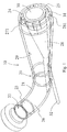
- Figure 1 shows, in a perspective, partially transparent view, a cutting device 10 for comminuting pasty substances with a nozzle 20 which has a nozzle housing 21.
- the nozzle housing 21 is designed as a tube with a bend.
- the nozzle 20 has an inlet flow cross-section 23 with an inlet flow cross-section 23 for better illustration is drawn in slightly offset.
- the pasty material to be comminuted is conveyed from the inlet 22 through the flow channel 26 formed in the nozzle housing 21 in the direction of an outlet 24 with an outlet flow cross section 25. This can be done by a pump or the like, which is connected to the nozzle 20 and upstream of the cutting device 10.
- a rotating cutting tool 30 with four cutting edges 31 is arranged at the outlet 24.
- the cutting tool 30 is driven via a drive shaft 52 which is led out of the nozzle housing 21 in the area of the bend.
- the drive shaft is mounted within the flow channel 26 in a central body 28 which, together with an inner wall 29 of the nozzle housing 21, forms the outlet flow cross section 25.
- the central body 28 extends from the outlet 24 into the flow channel 26 counter to the conveying direction.
- the central body 28 is conical and has a web 281 on its lateral surface, which rests against the inner wall 29 of the nozzle housing 21.
- the cone tip of the central body 28 is followed by an extension that extends as far as the inner wall 29 and ends there or in it, so that a continuous or almost continuous transition from the essentially circular inlet flow cross-section 23 to the outlet designed as an interrupted annular gap 27 - Flow cross section takes place.
- the extension can be manufactured separately from the conical central body 28, the central body 28 preferably forms an insert or a recess that reallocates the material flow from the inlet 22 to the outlet 24 without any further built-in components without dividing it into two separate material flows.
- the cross-sectional area within the flow channel 26 remains the same from the inlet 22 to the outlet 24 or at least does not decrease, even if the shape of the flow cross-section changes from the inlet 22 to the outlet 24.
- projections 271 protruding radially into the outlet flow cross-section are arranged, which are designed as cutting edges or as indentation elements and form incisions or depressions in the surface of the molded body to be produced, so that predetermined breaking points arise there the one defined break point and thus also a uniform one Length of the pieces from the molded body can be achieved.
- the projections 271 can be arranged on an attachment, attachment ring or on a sleeve on the central body 28.
- the attachment or the cuff can be interchangeably arranged on the central body 28 in order to be able to produce different distances between the predetermined breaking points or different geometries and to enable replacement in the event of wear.
- projections 271 on the central body 28 can also protrude from the outside, that is to say from the inner wall 29 of the nozzle housing 21, into the outlet flow cross section.
- projections can also be produced separately and attached to the nozzle housing 21 via an attachment, attachment ring or insert.
- such projections can also be formed in one piece.
- the cutting edges 31 on the cutting tool 30 are bent backwards against the direction of rotation, which is indicated by the arrow, so that a fin-like or saber-like cutting edge contour results.
- the cutting edges 31 have a bevel pointing away from the nozzle housing 21 in order to apply a separating pulse or a separating force when the pasty mass is cut or separated. As a result, easier separation and improved separation of the cut-off molded part from the flowing material stream pressed through the flow channel 26 is achieved.
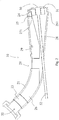
- FIG 2 shows the cutting device according to Figure 1 in a sectional view.
- Inlet 22 and outlet 24 are formed at opposite ends of nozzle 20.
- the central body 28, which has an essentially conical contour, is arranged within the flow channel 26, which is formed by the tubular nozzle housing 21.
- the drive shaft 52 which drives the cutting tool 30 with the blades 31, is guided through the central body 28.
- the blades 31 completely sweep over the outlet flow cross section 25, which is designed in the form of an interrupted annular gap.
- the drive shaft 25 is mounted in a sealed manner with respect to the material transported into the flow channel 26, so that a motor drive arranged outside the nozzle housing 21 does not interfere Contact with the pasty substance.
- the drive shaft 52 can be mounted axially displaceably within the central body 28, preferably mounted with a spring force in the direction of the basic position shown. In the event that an interfering object or a massive component hits a cutting edge 31 of the cutting tool 30, the cutting tool 30 can thus be displaced in the conveying direction so that the object can emerge and the cutting process can then be continued.
- the cutting edges 31 are arranged at a distance from the outlet 24 from the nozzle 20 and thus do not rest against the housing 21 or the central body or slide along them. Only the pasty material is severed by the cutting edges, so that wear can be reduced.
- the central body 28 is shown as a separate component which is pushed into the nozzle housing 21 and fixed to it.
- a web 281 is formed or arranged on the conical central body 28, which ensures that in the area of the outlet 24 the outlet flow cross-section is designed as an interrupted annular gap, in the illustrated embodiment as a circular, interrupted annular gap.
- Other annular gap shapes can also be present, for example polygonal shapes or oval shapes.
- these can also be made in one piece, for example in a casting process or in a forming process in which an initially tubular base part is taken as the nozzle housing 21 and the central body 28 is bent or molded inward .
- the nozzle housing 21 is enlarged in circumference over the conveying direction in the direction of the outlet 24, so that the pasty medium is not accumulated inside the nozzle 20. Since the central body 28 extends from the inner wall 29 in the direction of the flow channel 26 and is designed to increase volume in the conveying direction, preferably continuously to increase volume, and protrudes into the flow channel, the material flow is redistributed and reshaped in contact with the inner wall 29 and the outer contour of the central body 28, until the shape of the outlet flow cross section 25 is reached.
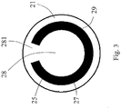
- a variant of a possible outlet opening is shown as an interrupted annular gap 27.
- the outlet flow cross section 25 is formed by the outer contour of the central body 28 and the inner wall 29 of the nozzle housing 21.
- the annular shape of the gap is interrupted by the web 281.
- the end contours of the annular gap 27 are formed by the shape of the web 28.
- the length of the shaped body to be produced is essentially defined by the length of the annular gap or the radian dimension of the interrupted outlet opening.
- FIG Figure 4 a variant is shown in which the web 281 forms different circular radii R1, R2.
- the center of the annular gap 27 is taken as the reference radius.
- the starting radius R1 is smaller than the end radius R2 when the cutting element (not shown) rotates in the direction of the arrow.
- the radius changes continuously from the starting radius R1 to the end radius R2 in the exemplary embodiment shown, so that a spiral-like shape of the molding produced results after it has been cut off.
- a continuous change in the radius is useful in order to produce briquettes or pellets that are as uniform as possible.
- different shapes of the annular gap 27 or of the interrupted annular gap 27 can also be used.
- Figure 5 shows two views of the molding 40 or pellet obtained by the cutting process.
- the pasty material was through an annular gap, as it is in the Figure 3 is shown, pressed through and cut transversely to the exit direction from the rotating cutting tool 30.
- the result is an interrupted, annularly curved parallelepiped, in which the length is essentially defined by the length of the annular gap.
- the molding has two end faces 41, which are formed by the web 281, at which the flow of the pasty material is separated from one another and pressed out of the outlet 24 in a bent shape.
- the cross-section of the end faces is a parallelepiped, there are a total of four longitudinal sides, an outer side 49 which rests on the inside 29 of the nozzle housing 21 at the outlet.
- the inside 48 rests against the outside of the central body 28 and lies opposite the outside 49. Furthermore, two are each other opposite long sides 43 are formed, which are formed in the longitudinal extension of the molded body 40 and are formed by the cutting edges 31 of the cutting tool 30 by means of successive cuts. With the device according to the invention, a separation from the subsequent material flow is achieved by a rotating cut running transversely to the exit direction along a longitudinal side 43 of the molded body 40 to be produced.
- the shape of the molded body 40 is initially dependent on the shape of the annular gap 27 or the outlet flow cross section 25. If an attachment or inserts are present within the outlet flow cross section 25, predetermined breaking points 47 or indentations in the outer long side can be created via elements located therein, such as cutting edges 49 or the inner long side 48 can be incorporated.
- the thickness of the space body 40 is influenced in particular by the flow speed of the pasty substance and the number of revolutions of the cutting tool together with the number of cutting edges 31 and their orientation and arrangement on the circumference of the cutting tool.
- the cut surfaces 43 of the shaped bodies 40 are not located on the end faces 41, but on the longitudinal sides 43 of the pellets.
- Figure 6 shows a schematic plan view of an exiting material flow that emerges from the nozzle housing 21.
- the annular gap is curved so that there is a curved fabric surface into the image plane.
- the cutting edge 31 moves in the direction of the arrow to the right, while the flow of material moves in the conveying direction in the direction of the arrow downwards.
- By setting the cutting edge 31 at an angle a diagonal division of an emerging, curved material surface takes place.
- the angular position of the cutting edge 31 results in a force component acting in the conveying direction, so that the cut molding 40 is separated from the subsequent material flow as shown and is moved away from the nozzle outlet with a slight angular momentum.
- FIG. 7 a schematic sectional view of the cutting device 10 is shown, in which the nozzle is formed as a nozzle housing 21 from a continuously conically widening tube.
- the inlet 22 faces opposite the outlet 24 a smaller diameter.
- a conical central body 28 is inserted, which is inserted into a slot of the nozzle housing 21, which will be explained later, and which is fixed to the nozzle housing 21.
- the central body 28 has a downwardly directed web 281 which penetrates the nozzle housing 21 and extends to the outlet-side end surface of the central body 28.
- the circumferential annular gap otherwise formed by the conical central body 28 is interrupted via the web 28.
- the central body 28 Since the conical central body 28 penetrates the nozzle housing 21, the central body 28 protrudes increasingly from the inner wall 29 from the inlet side into the flow channel 26 and completely or almost completely compensates for the increasing cross-sectional area due to the enlargement of the nozzle housing 21 in the outlet direction.
- the area of the respective flow cross-section thus remains essentially constant in the conveying direction, possibly increasing in order to relieve the pressure in the pasty substance which occurs during pumping through the nozzle 20.
- the drive shaft 52 is mounted inside the central body 28, optionally axially displaceable, and protrudes out of the nozzle housing 21, where it is then driven outside the nozzle housing 21.
- Saber-like cutting edges 31 are arranged on the cutting tool 30, by means of which the material pressed through the outlet 24 is cut transversely to the outflow direction and along the longitudinal extension of the respective shaped bodies 40 produced.
- the nozzle housing 21 and the central body 28 are designed as separate components and joined together.
- the outlet flow cross section is formed by the outer contour of the central body 28 and the inner contour of the inner surface 29 of the nozzle housing at the outlet 24.
- FIG. 8 shows a perspective sectional view of FIG Figure 7 , in which it can be seen that the conical central body 28 increases continuously from a passage area through the inner wall 29 near the inlet 22 in the direction of the outlet 24, so that the cross-sectional shape of the inlet cross-section 23 changes continuously until an interrupted annular gap is created .
- the longitudinal axis of the cone is not collinear with the longitudinal or central axis of the nozzle housing 21 in the outlet area, so that changing, non-rotationally symmetrical flow cross-sectional shapes result over the length of the flow channel.
- Within the flow channel 26 there is no separation or division into two separate material flows of the material being transported through, rather the material being transported is rearranged and reshaped until it is brought into a curved, flat shape.
- the two ends of the annular gap are separated via the web 281.
- a helical division of the pasty medium is then carried out via the cutting edges 31 or the at least one cutting edge 31.
- a separation in length can take place via the predetermined breaking points introduced during the further processing of the molded products.
- Figure 9 shows the cutting device in a partially assembled state, in which only the nozzle housing 21 with the central body 28 and the web 281 formed on the outer surface of the conical central body 28 can be seen.
- the central body 28 is via a slot, as for example in the Figure 11 with the reference numeral 218 is inserted into the housing.
- the web 281 protrudes through the nozzle housing 21.
- Figure 10 shows the assembly state according to Figure 9 in a rear view from the inlet side. It can be seen that the central body 28 with the conical basic shape penetrates the wall of the nozzle housing 21. Material flowing from the inlet side to the outlet side is moved around the central body 28 at the point of penetration and lies against the inner wall 29 of the nozzle housing 21 and on the outer wall of the central body 28 and around the central body 28 without any material flow separation occurring. A bore 285 for receiving the drive shaft 52 is machined within the central body 28.
- Figure 11 shows the nozzle housing 21 in an individual representation with the slot 218 extending in the conveying direction up to the outlet 24.
- the slot 218 is like this shaped so that the web 281 is received tightly and the conical central body 28 rests tightly against the nozzle housing 21, so that a tight seal and as continuous a transition as possible from the inner wall 29 of the nozzle housing to the conical central body 28 takes place.
Description
- Die Erfindung betrifft eine Schneidvorrichtung zum Zerkleinern von pastösen Stoffen mit einer Düse mit einem Düsengehäuse, das zumindest einen Einlass mit einem Eintritts-Strömungsquerschnitt, durch den der pastöse Stoff in die Düse eintritt, und einen Auslass mit einem Austritts-Strömungsquerschnitt, durch den der pastöse Stoff aus der Düse austritt, sowie einen von dem Einlass zu dem Auslass führenden Strömungskanal aufweist, mit einem an dem Auslass angeordneten rotierenden Schneidwerkzeug zum Schneiden des austretenden pastösen Stoffes. Die Erfindung betrifft ebenfalls ein System aus einer solchen Schneidvorrichtung und einer Weiterverarbeitungseinrichtung, die mit der Schneidvorrichtung gekoppelt ist.
- Die Erfindung betrifft insbesondere eine Schneidvorrichtung und ein System zum Zerkleinern und zum Vereinzeln insbesondere von solchen pastösen Stoffen mit schwer oder nicht zerteilbaren Fasern und/oder Partikeln. Solche pastösen Stoffe werden zu Pellets zerkleinert, so dass formlose Massen zuverlässig zu gleichförmigen Formkörpern vereinzelt werden können. Gleichzeitig mit der Zerkleinerung und Vereinzelung können die Formkörper, die mit Fasern und Fremdstoffen verunreinigt und auch oberflächig klebrig sein können, in ein umgebendes Fluid eingebracht werden, beispielsweise in eine Vakuum- oder Hochdruckumgebung.
- Bei aus dem Stand der Technik bekannten Verfahren zum Pelletieren pastöser Stoffe oder gestaltloser Massen wird der Stoff durch eine Formdurchbrüche aufweisende Matrize oder Düsenplatte gepresst, der Schneideinrichtung vorgelagert oder nachgelagert sind, um die entstehenden Schnüre oder Materialstränge mit Sollbruchstellen zu versehen oder vollständig über den Querschnitt der aus den Formausbrüchen austretenden Massen zu teilen. Solche Vorrichtungen sind aus der
EP 0 225 351 A1 , derDE 196 17 972 B4 oder derDE 40 13 760 C2 bekannt. Diesen Schneidvorrichtungen gemeinsam ist, dass bei verändertem Materialdurchsatz die Bewegung der Schneideinrichtung angepasst wird, um eine konstante Pelletlänge zu erhalten. Dadurch entstehen insbesondere bei Produktschwankungen, also bei nicht kontanten Zusammensetzungen des zu vereinzelnden Stoffes und bei sehr großen und sehr kleinen Materialdurchsätzen, Probleme bei der Vereinzelung der geschnittenen Formkörper. - Aus der
EP 0 945 172 A1 ist ein Verfahren bekannt, bei dem ein pumpbarer Stoff durch einen aus zwei Teilen einer Vorrichtung gebildeten Ringspalt nach außen gefördert wird, wobei zumindest ein Teil der beiden den Spalt und die Öffnungen im Außenring bildenden Teile drehbar ist und sich im Gehäuse sowie im Stoff bewegt. Die dabei entstehenden Partikel sind ungleichmäßig und werden mit einem hohen Impuls weggeschleudert. - Aus der
DE 197 10 302 A1 ist eine Vorrichtung bekannt, bei der pastöse Medien zerkleinert werden, indem ein Schredder vor einem Produktauslass die Masse mit einer mit Schlagzähnen versehenen Walze von dem Produktstrom abschlägt. Dadurch werden ungleichförmige Partikel mit einem hohen Impuls erzeugt. - Aus der
EP 1 618 947 A1 ist eine Vorrichtung zum Erzeugen von Pellets beschrieben, bei der die Länge von zuvor durch eine Matrize erzeugter Schnüre oder Stränge unabhängig von der Vorschubgeschwindigkeit des hindurchgepressten Materials und der Drehgeschwindigkeit von Trennmessern gewählt werden kann. Dazu sind zwischen den Formdurchbrüchen in der Matrize Stege angeordnet, die mindestens so breit wie ein Messer sind. Das Schneidwerkzeug wird zur Ausführung eines Schneidvorganges intervallmäßig im Kreis gedreht, wenn die Stränge die jeweils gewünschte Länge erreicht haben. Anschließend verbleiben die Messer in der jeweiligen Ruheposition vor einem Steg. - Nachteilig an den aus dem Stand der Technik bekannten Lösungen ist, dass der Stoffstrom durch Formdurchbrüche gepresst und dadurch getrennt werden muss, um gleichförmige Partikel zu erzeugen, bevor die Schnüre oder Stränge quer geteilt werden. Der eigentliche Trennvorgang ist dabei unproblematisch, jedoch wird ein hoher Druck zum Verpressen des pastösen Stoffes durch die Öffnungen der Matrize benötigt. Da die meisten pastösen Stoffe inkompressibel sind, ist der Energieaufwand für das Durchpressen sehr hoch. Darüber hinaus wird das eingesetzte Material hoch belastet und die pastösen Stoffe werden hohen Druckbeanspruchungen und Temperaturerhöhungen infolge der Krafteinwirkungen ausgesetzt. Darüber hinaus ist diese Art der Herstellung von Pellets anfällig für Verstopfungen, insbesondere wenn die pastösen Stoffe Fasern, Haare, Drähte, Störstoffe oder Rußpartikel aufweisen. Darüber hinaus neigen die entstehenden Schnüre aus pastösem Material nach dem Schneiden stark zum erneuten Verkleben und müssen aufwendig voneinander getrennt gehalten oder gegebenenfalls zusätzlich zerkleinert werden. Dies geschieht meist durch Schneideinrichtungen vor dem Durchtritt des Stoffes durch die Matrize, um Sollbruchstellen zu erzeugen. Dazu bewegt sich ein Schneidinstrument direkt auf der Innenseite der Matrize, so dass sowohl die Matrize als auch das Schneidinstrument einem sehr hohen Verschleiß und einer sehr hohen mechanischen Belastung unterliegen.
- Die
DE 1 779 054 A betrifft eine Vorrichtung zum Plastifizieren und Granulieren von thermoplastischen Kunststoffen. Die Vorrichtung besteht aus einem konisch ausgebildeten Rotor, der in einem Hohlkörper gleichachsig rotiert und an einem Austrittsspalt eine zylindrische Verlängerung aufweist. Der zylindrischen Verlängerung ist eine Verlängerungswelle angeschlossen, auf welcher in axialer Richtung verschiebbar eine Buchse angeordnet ist, welche über Kugellager eine Halterung trägt. Fest mit der Halterung ist ein Messerring verbunden, auf dem Trennmesser schraubenlinienförmig angeordnet sind. Der Messerring ist mit dem Hohlkörper nicht fest verbunden, sondern wird von Stiften gegen ein Verdrehen gesichert. Der Messerring ist starr mit der Halterung verbunden und wird von dieser geführt. - Die
US 3 025 565 A betrifft eine Vorrichtung zum kontinuierlichen Formen geformter plastifizierter Massen mit einem Gehäuse und einem zentral daran angeordneten, konischen, angetriebenen Rotor und einer daran befestigten Extruderschnecke. An dem Rotor sind Rippen angeordnet, die das Material in Förderrichtung bewegen. Die über den Rotor hinaus transportierten plastifizerten Bänder oder Streifen werden von einem Messer abgeschnitten und fallen in den Einlassbereich der Extruderschnecke. - Die
US 1 987 358 A betrifft unter anderem eine Vorrichtung zum Herstellen von Produkten aus Kunststoffen oder Keramikmaterialien wie Ton, Schiefer oder Mischungen daraus. Die Materialien werden durch eine Düse extrudiert, so dass sich längliche Streifen ausbilden, die abgetrennt und anschließend in einer Atmosphäre mit geringerem Umgebungsdruck weiterverarbeitet werden. - Aufgabe der vorliegenden Erfindung ist es, eine Vorrichtung und ein System zum Zerkleinern von pastösen Stoffen bereitzustellen, mit denen pastöse Stoffe zuverlässig mit einem möglichst geringen Energieaufwand zu Formteilen oder Pellets zerkleinert werden können.
- Erfindungsgemäß wird diese Aufgabe durch eine Schneidvorrichtung mit den Merkmalen des Hauptanspruches sowie ein System mit den Merkmalen des nebengeordneten Anspruches gelöst. Vorteilhafte Ausgestaltungen und Weiterbildungen der Erfindung sind in den Unteransprüchen, der Beschreibung sowie den Figuren offenbart.
- Die erfindungsgemäße Schneidvorrichtung zum Zerkleinern von pastösen Stoffe mit einer Düse mit einem Düsengehäuse, das zumindest einen Einlass mit einem Eintritts-Strömungsquerschnitt, durch den der pastöse Stoff in die Düse eintritt, und einen Auslass mit einem Austritts-Strömungsquerschnitt, durch den der pastöse Stoff aus der Düse austritt, sowie einen von dem Einlass zu dem Auslass führenden Strömungskanal aufweist und mit einem an dem Auslass angeordneten, rotierenden Schneidwerkzeug zum Schneiden des austretenden pastösen Stoffes sieht vor, dass der Austritts-Strömungsquerschnitt die Form eines insbesondere unterbrochenen Ringspaltes aufweist, der durch einen sich in Förderrichtung des pastösen Stoffes im Querschnitt vergrößernden Zentralkörper innerhalb der Düse und einer Innenwand des Strömungskanals gebildet ist. Die Düse mit dem Düsengehäuse ist im Wesentlichen rohrförmig, wobei das Düsengehäuse geradlinig ausgerichtet oder auch gebogen sein kann. Vorzugsweise weist das Düsengehäuse nur eine Biegung mit einem vergleichsweise großen Biegeradius auf. Das Gehäuse weist nur einen Auslass auf, der einen Austritts-Strömungsquerschnitt bildet, durch den der pastöse Stoff aus der Düse austritt. Der Austritts-Strömungsquerschnitt hat die Form eines Ringspaltes, insbesondere eines unterbrochenen Ringspaltes, wobei die Kontur des Ringspaltes bevorzugt kreisförmig ausgebildet ist, grundsätzlich besteht jedoch auch die Möglichkeit, dass die Kontur des Ringspaltes oval oder polygonal ausgebildet sein kann. Der Ringspalt wird durch einen sich in Förderrichtung des pastösen Stoffes im Querschnitt vergrößernden Zentralkörpers zusammen mit einer Innenwand des Strömungskanals gebildet. Der Zentralkörper ist somit innerhalb des Strömungskanals angeordnet oder ausgebildet und sorgt dafür, dass sich der von dem Einlass zum Auslass geförderte Stoffstrom umformt oder umlagert, so dass keine voneinander getrennten Stoffströme durch einen Auslass oder durch Formausbrechungen in einer Matrize hindurchgepresst werden müssen. Dies hat den Vorteil, dass durch den sich in Richtung auf den Auslass vergrößernden Zentralkörper eine Umlagerung, Umlenkung oder Umleitung des Stoffstromes ergibt, ohne dass dieser geteilt wird. Dadurch entstehen keine Strömungshindernisse oder Strömungsabrisse, an denen sich Stauungen oder Verklebungen bilden oder Fasern, Drähte oder andere Materialien innerhalb der pastösen Masse verfangen können. Das Düsengehäuse kann einteilig ausgebildet und in einem Urformverfahren hergestellt sein, alternativ dazu kann eine mehrteilige Ausgestaltung mit Befestigungsmitteln aneinander vorgesehen sein, was eine Bearbeitung der Innenwand des Strömungskanals sowie die Formgestaltung des Strömungskanals erleichtern kann. Die Formgestaltung der Pellets erfolgt nicht durch Matrizen, sondern durch eine Ausgestaltung eines Zwischenraumes einer Innenwand eines Strömungskanals und einem darin befindlichen Zentralkörper. In der Erfindung ist vorgesehen, dass der Zentralkörper sich von der Innenwand des Strömungskanals in Förderrichtung geneigt in den Strömungskanal hinein erstreckt, so dass eine kontinuierliche oder quasi kontinuierliche Umformung des Strömungsquerschnitts entlang der Förderrichtung innerhalb des Strömungskanals erfolgt. Durch den Ansatzpunkt an der Innenwand des Strömungskanals wird das pastöse Material um den Ansatz des Zentralkörpers herum geleitet. Der Zentralkörper befindet sich nicht und muss sich nicht zentral innerhalb des Strömungskanals befinden, sondern nur innerhalb des Strömungskanals und ragt in diesen hinein. Zumindest im Bereich des Ansatzes, also an dem dem Einlass zugewandten Ende des Zentralkörpers, kann dieser eine Kegelform aufweisen, die die Innenwand durchdringt oder von dieser in den Strömungskanal hinein sich wölbt, so dass der Stoffstrom in Form einer gebogenen Fläche umgelagert wird, die in den Austritts-Strömungsquerschnitt in Form eines Ringspaltes mündet.
- Der Zentralkörper kann einstückig mit dem Düsengehäuse ausgebildet sein oder aber, wenn das Düsengehäuse mehrteilig ausgebildet ist, einstückig mit einem Teil eines Düsengehäuseteils ausgebildet sein, um eine kontinuierliche Innenoberfläche oder eine durchgehende Innenwand des Strömungskanals zu gewährleisten. Durch eine einstückige Ausgestaltung, beispielsweise als Gussteil, als additiv hergestelltes Bauteil oder als gesintertes Bauteil können komplexe Geometrien ohne Schnittstellen erzeugt werden. Der Montageaufwand wird verringert und aufgrund der geschlossenen Innenoberfläche eine vergrößerte Haltbarkeit gewährleistet. Alternativ zu einer einstückigen Ausgestaltung des Zentralkörpers mit dem Düsengehäuse oder einem Düsengehäuseteil kann der Zentralkörper als separater Einsatz in dem Strömungskanal befestigt sein. Durch eine separate Ausgestaltung des Zentralkörpers ist es möglich, unterschiedliche Zentralkörper in ein Düsengehäuse einzubauen, um beispielsweise eine größere Variantenvielfalt bei der Anpassung der Schneidvorrichtung an die gewünschten Leistungsparameter zu erreichen. Je nach zu verarbeitendem Stoff können unterschiedliche Zentralkörper in ein Düsengehäuse eingesetzt und daran festgelegt werden, beispielsweise um die Geometrie des Ringspaltes, der zwischen der Innenwand des Strömungskanals und der Außenkontur des Zentralkörpers gebildet wird, an die gewünschte Pelletgröße oder an das verwendete Material anzupassen. Darüber hinaus können bei Verschleiß an dem Zentralkörper Wartungsarbeiten vorgenommen oder ein Austausch erleichtert werden. Darüber hinaus können entsprechende Materialpaarungen vorgesehen werden, so dass unterschiedliche Materialien zur Herstellung der Schneidvorrichtung, insbesondere des Düsengehäuses und des Zentralkörpers verwendet werden, die eine an die jeweils vorhandenen Belastungen angepasste Materialauswahl ermöglicht. Auch kann die Herstellung einer teilweisen komplexen Struktur mit einem gebogenen Strömungskanal durch eine mehrteilige Ausgestaltung erleichtert werden.
- Eine Weiterbildung der Erfindung sieht vor, dass sich die Strömungsquerschnittsfläche des Strömungskanals in Förderrichtung nicht verringert. Auch die Fläche des Austritts-Strömungsquerschnitts ist nicht kleiner als die Fläche des Eintritts-Strömungsquerschnitts, bevorzugt ist sie zumindest gleich der Fläche oder größer als die Fläche des Eintritts-Strömungsquerschnitts, um einerseits das pastöse Material zu entspannen oder zumindest zu komprimieren, so dass nach Möglichkeit keine oder nur eine geringe Druckerhöhung innerhalb des geförderten Stoffes vor dem Auslass erfolgt. Bei einem nicht vorhandenen Staudruck durch eine Flächenverringerung im Bereich von Matrizen können hohe Volumenströme bei nur einem geringen Druckverlust erreicht werden. Auch empfindliche Materialien können daher in der Schneidvorrichtung verarbeitet werden. Darüber hinaus sind keine Druckschwankungen in einer vorgeschalteten Fördereinrichtung zu erwarten, die beispielsweise bei unterschiedlich hohen Wasseranteilen innerhalb des pastösen Stoffes auftreten können. Insbesondere bei der Verarbeitung von Mehrphasengemischen kann es sonst zu Kompressibilitätsschwankungen kommen, die nachteilige Auswirkungen auf den Antrieb bzw. die Pumpe sowie auf eine Materialbelastung haben.
- In einer Ausgestaltungsform der Erfindung ist der Zentralkörper konisch ausgebildet, wobei dieser sich kontinuierlich im Querschnitt vergrößernd ausgebildet sein kann. Auch bei einer nicht konischen Formgebung des Zentralkörpers kann dieser sich kontinuierlich im Querschnitt vergrößernd ausgebildet sein, wenn eine von einem Konus abweichende Formgebung gewünscht ist. Zusammen mit der sich vergrößernden Querschnittsfläche des Zentralköpers entlang der Förderrichtung von dem Einlass zum Auslass ist vorgesehen, dass sich auch der Innendurchmesser der Innenwand des Strömungsgehäuses vergrößert, um eine zumindest gleichbleibende Fläche des Strömungsquerschnittes entlang der Förderrichtung innerhalb des Strömungskanals zu gewährleisten. Somit entsteht der Ringspalt, insbesondere ein unterbrochener Ringspalt, durch eine kontinuierliche Querschnittsveränderung über die Länge des Strömungskanals, was eine Umlagerung des Stoffstromes ohne eine Aufteilung in mehrere Teilströme zur Folge hat.
- Der Zentralkörper kann als massives Bauteil ausgebildet sein oder als ein angeformtes Formstück bei einer einstückigen Ausgestaltung. Alternativ kann der Zentralkörper als Hohlkörper ausgebildet sein und beispielsweise bei einer Ausgestaltung des Strömungskanals als Rohr durch ein zunehmendes Eindrücken mit einem korrespondierenden Aufweiten auf der gegenüberliegenden Seite erfolgen, so dass über eine Umformung der Zentralkörper aus einem einteiligen Rohr hergestellt ist. Die Form des unterbrochenen Ringspaltes ist dann im Wesentlichen C-förmig oder angenähert C-förmig. Die jeweiligen Enden eines unterbrochenen Ringspaltes können geradlinig, spitz zulaufend oder abgerundet sein und sind abhängig von den jeweiligen Prozessparametern, verwendeten Materialien, Fertigungsverfahren sowie der zu zerteilenden oder zu zerschneidenden pastösen Stoffe gestaltet.
- Bei einer nicht einteiligen Ausgestaltung des Zentralkörpers kann dieser längsverschieblich und insbesondere federbelastet entgegen der Verschieberichtung an dem Gehäuse gelagert sein. Durch eine Längsverschieblichkeit des Zentralkörpers entlang der Längserstreckung des Strömungskanals in oder entgegen der Förderrichtung ist es möglich, die Form beziehungsweise die Fläche des Austritts-Strömungsquerschnittes zu verändern und an die jeweiligen Prozessparameter anzupassen. In der jeweils längsverschobenen Position ist der Zentralkörper an dem Düsengehäuse festlegbar oder arretierbar. Bei einer federbelasteten Lagerung des Zentralkörpers innerhalb des Düsengehäuses besteht die Möglichkeit, dass bei einer Förderung des pastösen Materials größere Feststoffe, die nicht durch den Austritts-Strömungsquerschnitt hindurchtreten können, den Zentralkörper verschieben und somit eine Vergrößerung des Austritts-Strömungsquerschnittes bewirken. Da sich der Zentralkörper entgegen der Förderrichtung verjüngt, vergrößert sich bei einer Verschiebung des Zentralkörpers in Förderrichtung der Austritts-Strömungsquerschnitt, so dass Störungen vermieden und Feststoffe oder andere Störkörper durch den Strömungskanal bis aus dem Auslass heraus befördert werden können. Über die Federbelastung wird der Zentralkörper dann wieder in die Ausgangsstellung zurückbewegt.
- In einer vorteilhaften Ausgestaltung ist eine Antriebswelle des Schneidwerkzeuges in dem Zentralkörper gelagert, so dass durch den Zentralkörper hindurch das Schneidwerkzeug angetrieben werden kann. Die Antriebswelle reicht bevorzugt durch den Zentralkörper hindurch und tritt aus dem Düsengehäuse aus. Die Antriebswelle verbindet das rotierende Schneidwerkzeug mit einem außerhalb des Düsengehäuses gelagerten Antrieb, sofern das Schneidwerkzeug nicht durch einen Direktantrieb angetrieben wird. Da die Welle oder der Direktantrieb innerhalb des Zentralkörpers und somit innerhalb des Düsengehäuses verläuft, findet keine Stoffberührung der Welle mit dem pastösen Stoff statt. Es befinden sich somit keine beweglichen Teile innerhalb des Düsengehäuses, die mit dem zu zerteilenden, pastösen Stoff in Berührung kommen können, so dass eine Kontaminierung des pastösen Stoffes oder auch ein Verschleiß der Welle oder des Antriebes nicht in Frage kommt.
- Bevorzugt ist das Düsengehäuse mit einer Biegung versehen, so dass der Strömungskanal ebenfalls eine Biegung ausführt. Dadurch wird das Herausführen der Antriebswelle aus dem Düsengehäuse erleichtert. Die Welle, insbesondere wenn sie als starre Welle ausgebildet ist, kann dann geradlinig im Bereich der Biegung in den Zentralkörper eingeführt werden und erstreckt sich innerhalb des Zentralkörpers geradlinig bis zum Auslass. Bevorzugt ist die Welle derart gelagert, dass sie im Mittelpunkt des Ringspaltes oder, bei einer unrunden oder polygonalen Ausgestaltung der Form des Austritts-Strömungsquerschnittes, zentral darin angeordnet ist, so dass ein Schneidelement oder eine Schneide an dem Schneidwerkzeug den gesamten Austritts-Strömungsquerschnitt überstreichen kann. Die Welle kann in einem Außengehäuse und anschließend in dem innenliegenden Zentralkörper verlaufen, ohne das Produkt zu berühren. Sofern der Zentralkörper durch eine Eindrückung oder Umformung des Strömungskanals oder des Düsengehäuses ausgebildet wird, verläuft die Welle stets außerhalb des Düsengehäuses auf der Außenseite in einer durch die Eindrückung ausgebildeten Falte oder Einstülpung und berührt die Außenseite des Gehäuses vorzugsweise nicht.
- Die Antriebswelle selbst kann verschiebbar ausgebildet sein, so dass auch das Schneidwerkzeug verschiebbar relativ zu dem Auslass gelagert ist. Somit kann auf Stoffschwankungen oder Verblockungen reagiert werden, ohne den Stoffstrom oder die Zerkleinerung desselben unterbrechen zu müssen. Die Antriebswelle kann ebenfalls federbelastet in Richtung auf den Auslass gelagert sein, so dass bei Auftreffen von festen Materialien auf das Schneidwerkzeug oder Schneiden des Schneidwerkzeuges eine Axialverlagerung von dem Auslass weg ermöglicht wird und nach Beseitigung des Hindernisses eine Rückkehr in die Ausgangsstellung erfolgt. Die Antriebswelle kann auch als biegsame Welle ausgebildet sein.
- Der Austritts-Strömungsquerschnitt kann in einer Ausführungsform als einzelner, unterbrochener Ringspalt ausgebildet sein, wobei der Zentralkörper an dem Austritts-Strömungsquerschnitt einen einzigen Steg ausbildet. Über den Steg wird der Ringspalt unterbrochen. Der Steg kann in Abhängigkeit von den Materialeigenschaften des zu zerkleinernden Stoffes zwischen 1 Grad und 180 Grad, vorzugsweise zwischen 60 Grad und 10 Grad, insbesondere zwischen 25 Grad und 15 Grad des Gesamtumfanges betragen, wobei die Form und Abmessungen des Steges die entstehenden Formkörper oder Pellets in ihrer Form beeinflussen. Die Länge der Pellets wird durch das Bogenmaß beziehungsweise den Anteil am Umfang des unterbrechungsfreien Teils des Ringspaltes an dem Austritts-Strömungsquerschnitt bestimmt. Die Kontur des Steges kann sich in Strömungsrichtung verändern, insbesondere kann die Stegbreite oder Steghöhe sich verringern oder verbreitern, um eine verbesserte Abtrennung und ein Ablösen von dem Schneidelement zu erreichen.
- Der Ringspalt muss keinen konstanten Kreisradius oder einen konstanten Kompromissradius aufweisen, vielmehr besteht die Möglichkeit, dass der unterbrochene Ringspalt verschiedene mittlere Kreisradien an dem Anfang und dem Ende aufweist, um so die Schnittgeometrien und Ablösungsverhalten des Materials zu beeinflussen.
- Der Zentralkörper kann als Kegel mit einem an einem an der Mantelfläche angeordneten oder ausgebildeten Steg ausgebildet sein, der in den Strömungskanal eingepasst oder darin eingeformt ist. Bevorzugt geht der Eintritts-Strömungsquerschnitt kontinuierlich in den Austritts-Strömungsquerschnitt über, insbesondere bleibt die Fläche des Strömungsquerschnittes entlang des Strömungskanals im Wesentlichen gleich. Die Differenz zwischen den Innendurchmesser, der Innenwand und dem Außendurchmesser des Zentralkörpers kann sich über den Umfang verändern, bleibt jedoch vorzugsweise gleich.
- In einer Weiterbildung der Erfindung sind zum Erzeugen von Sollbruchstellen in den pastösen Stoff an dem Auslass, insbesondere in dem Ringspalt, Vorsprünge angeordnet oder ausgebildet, die in den Ringspalt im Austritts-Strömungsquerschnitt hineinragen. Aufgrund der durch die Umformung des pastösen Stoffes an der Außenseite entstehenden Zugspannungen ist es vorteilhaft, wenn die Vorsprünge von dem Außenumfang, also von der Innenwand des Düsengehäuses in den Austritts-Strömungsquerschnitt hineinragen. Die Vorsprünge können in dem Gehäuse selbst ausgebildet oder in Gestalt eines Aufsatzes nach dem Austritt und vor dem Schneiden des pastösen Materials angeordnet sein. Der Aufsatz auf das Gehäuse dient zum Formen, Einritzen oder Verpressen oder auch Leiten des Stoffstromes zu den Schneiden des Schneidwerkzeuges. Die Vorsprünge dienen zur Erzeugung von Sollbruchstellen in dem pastösen Stoff und in dem zerkleinerten, in Pelletform vorliegenden Formkörper, über die die Länge von Bruchstücken nach einer beispielsweisen Trocknung und mechanischen Belastung vorbestimmt werden kann. Damit an den Vorsprüngen keine Störstoffe anhaften können, ist es vorteilhaft, diese entgegen der Strömungsrichtung des Stoffes verjüngend keilförmig auszubilden.
- Das Schneidwerkzeug weist zumindest eine von innen nach außen, entgegen der Rotationsrichtung geneigte Schneide auf. Die Schneide kann gebogen sein, ähnlich einer Rückenflosse, einer Finne oder einem Säbel. Es können mehrere rotationssymmetrisch angeordnete Schneiden an dem Schneidwerkzeug vorhanden sein, wobei die Schneiden von der Antriebswelle oder einem Direktantrieb in Rotationen versetzt werden. Die Schneiden können auswechselbar an dem Schneidwerkzeug angeordnet sein und können in einem vorbestimmten Winkel zur Ebene des Schneidwerkzeuges auf dem Umfang des Schneidwerkzeuges angeordnet sein. Über den Winkel der Schneiden lässt sich einstellen, wie weit eine Trennung von dem nachfolgenden Materialstrom erfolgt. Die Anzahl der Schneiden richtet sich nach der erforderlichen Drehzahl, um die jeweils gewünschte Breite der Pellets oder der zu erzeugenden Formkörper zu bestimmen. Üblicherweise werden ein bis vier rotierenden Schneiden eingesetzt, die mit einer verschleißreduzierenden Beschichtung versehen sein können. Die Schneiden weisen vorzugsweise eine Schräge auf, die von der Düse weg weist, um einen zusätzlichen Trennimpuls bereitzustellen.
- Das Schneidwerkzeug kann in Förderrichtung axial beabstandet zu dem Zentralkörper und zu dem Düsengehäuse gelagert sein, so dass die Schneiden das Düsengehäuse und den Zentralkörper oder einen daran befindlichen Aufsatz nicht berühren. Dadurch wird der Verschleiß des Schneidwerkzeuges und des Aufsatzes verringert. Alternativ zu einer Ausgestaltung des Schneidwerkzeuges mit klingenartigen oder säbelartigen Schneiden können auch Schneidelemente wie Drähte oder Schnüre an dem Schneidwerkzeug angeordnet sein oder durch Luft, Dampf oder Flüssigkeitsstrahlen ausgebildet werden, die das pastöse Material schneiden.
- Um optional unterschiedliche Dicken der zu erzeugenden Formkörper oder Pellets erzeugen zu können, kann die Anordnung der Schneiden oder Schneidelemente unregelmäßig an dem Umfang des Schneidwerkzeuges gestaltet sein, wodurch in einem Arbeitsgang unterschiedlich dicke Chargen an Pellets oder Formkörpern erzeugt werden können.
- Durch die Axialbeabstandung von dem Zentralkörper, dem Steg und dem Düsengehäuse bewegt sich die Schneide oder bewegen sich die Schneiden oder Schneidelemente ausschließlich in dem pastösen Stoff und nicht vergleichbar einer Schere berührend auf dem Gehäuse, dem Steg, dem Aufsatz oder dem Zentralkörper. Dies verringert den Verschleiß der Messer, und die Beeinflussung der erzeugten Formkörper oder Pellets durch die Messer ist minimal.
- Um ein Wegschleudern der abgeschnittenen Formkörper zu erleichtern, sind die Schneiden in einem Winkel zur Rotationsebene des Schneidwerkzeuges einstellbar ausgerichtet. Der Winkel der Schneiden zur Ebene des Rotationswerkzeuges beträgt zwischen 0 und 60 Grad, vorzugsweise zwischen 2 Grad und 15 Grad und richtet sich insbesondere nach der zu erwartenden Drehungsgeschwindigkeit und der Ausströmgeschwindigkeit des pastösen Stoffes.
- Bevorzugt umgibt der Ringspalt beziehungsweise die Kontur des Ringspaltes den Zentralkörper um mehr als 180 Grad. Bei einer Zentralanordnung des Schneidwerkzeuges liegt die Drehachse des Schneidwerkzeuges im Wesentlichen im Zentrum des Ringspaltes oder im Mittelpunkt des Ringspaltes, sofern dieser kreisförmig ausgebildet ist. Die Drehachse des Schneidwerkzeuges wird somit ebenfalls von dem Ringspalt um mehr 180 Grad umgeben.
- Das erfindungsgemäße System mit einer Schneidvorrichtung, wie sie oben beschrieben worden ist, und eine Weiterverarbeitungseinrichtung sieht vor, dass die Schneidvorrichtung an der Weiterverarbeitungseinrichtung angeordnet ist, wobei in der Weiterverarbeitungseinrichtung der getrennte, zerkleinerte, pastöse Stoff, der nunmehr in Form von Formkörpern oder Pellets vorliegt, weiterverarbeitet wird. Unter Trennen, Schneiden, Zerkleinern oder Teilen wird allgemein das Auflösen eines Stoffzusammenhanges verstanden, so dass ein getrennter Formkörper entsteht. Als zu verarbeitende Stoffe können pastöse Biomassen oder Mehrphasengemische eingesetzt werden, insbesondere auch druck-, temperatur- oder scherempfindliche oder dilatante oder abrasive Massen, deren Trennung einen hohen Verschleiß von Extrudern, Pumpen und Matrizen hervorrufen kann sowie pastöse Massen mit einem hohen Faseranteil und sehr langen und schwer schneidbaren Fasern, Haaren oder Störstoffen, bei denen andere Schneideinrichtungen verblocken würden oder aufwendige Trenn- oder Schneideinrichtungen vor den Austrittsöffnungen vorgehalten werden müssen. Das System sieht insbesondere eine Trocknung bei der Verarbeitung entwässerter Schlämme, insbesondere Klärschlämme vor. Die Pellets können thermisch, mechanisch oder chemisch behandelt werden oder reagieren, anschließend oder teilweise gleichzeitig können sie geröstet, frittiert, getrocknet, granuliert, fluidisiert, pneumatisch transportiert, gelagert, gekühlt, erwärmt, gemischt homogenisiert oder in eine neue, chemische Lösung eingebracht oder erhärtet bzw. ausgehärtet werden. Neben einer Verwendung für Abwässer- oder in der Schlammbehandlung kann das System auch zur Herstellung von Lebensmitteln, Futtermitteln, Baustoffen und ähnlichen Zwischen- und Endprodukten eingesetzt werden. Vorteilhafterweise werden durch die Schneideinrichtung gleichmäßige, gleichförmige Formkörper hergestellt, die in der Regel bei einer runden Ausgestaltung oder einer angenähert runden Ausgestaltung des Ringspaltes als gebogenes Parallelepiped beschrieben werden können. Es entsteht ein unterbrochen-ringförmiges, gebogenes Parallelepiped bei Verwendung eines unterbrochenen Ringspaltes, sofern ein vollständiger Ringspalt vorhanden ist, entsteht eine Wendel. Die Form der erzeugten Pellets ist abhängig von der Form der Austrittsöffnung, dem Vorhandensein oder Nichtvorhandensein von Schneidelementen, die in den Ringspalt hineinragen und Sollbruchstellen erzeugen, sowie der Breite, des Winkels, des Versatzes der Kreisradien von Anfang und Ende des unterbrochen ringförmigen Austritts und Ausführungen des Steges. Weitere Einflussgrößen sind die eingesetzten Stoffe, die Strömungsgeschwindigkeit des Stoffes, die Richtung der Ausströmung sowie der Anordnung, Ausführung und Anzahl der Schneiden auf dem Schneidwerkzeug sowie deren Orientierung, die Temperatur der Düse und die Umgebungsbedingungen der Weiterverarbeitungseinrichtung.
- In der Weiterverarbeitungseinrichtung kann ein Unter- oder Überdruck herrschen, der auch an dem Austritts-Strömungsquerschnitt anliegt. Durch die Förderung in einen Überdruckraum der Weiterverarbeitungseinrichtung wird der pastöse Formkörper ohne Druckveränderung in die Weiterverarbeitungseinrichtung transportiert. Dies führt dazu, dass die in der Regel noch feuchten und klebrigen Formkörper direkt in einer Überdruckatmosphäre verarbeitet werden können, ohne dass sie wieder aneinander anhaften können oder eine separate Transporteinrichtung und eine Druckschleuse, insbesondere eine Zellenradschleuse, in eine Überdruckumgebung eingeführt werden müssten. So können bspw. ein direkter Eintrag in einen Trockner, insbesondere einen Wirbelschichtverdampfungstrockner, eine Rösteinrichtung oder eine Frittiereinrichtung, Granuliereinrichtung, Fluidisierungseinrichtung, Kühleinrichtung, einen Mischer oder Homogenisierer erfolgen, wobei sich die Transportstrecke verringert, keine nachträgliche Anhaftung der erzeugten Formkörper aneinander ergibt und insbesondere bei Wirbelschichtverdampfungstrocknern oder Fluidisierungseinrichtungen kaum eine Wandberührung mit Anhaftungen erfolgt. Ebenso kann der Stoff in eine Unterdruckatmosphäre gefördert werden, wobei sich hier das Problem der Anhaftung voneinander getrennter Formkörper nicht oder weniger dringlich stellt.
- Ein Verfahren zum Zerkleinern von pastösen Stoffen sieht unter anderem die Schritte des Durchleitens eines pastösen Stoffes durch eine Düse vor, wobei die Querschnittsform des pastösen Stoffes während des Durchtritts durch die Düse von einem Einlass zu einem Auslass der Düse von einem Eintritts-Strömungsquerschnitt zu einem davon abweichenden Austritts-Strömungsquerschnitts verändert wird. Der pastöse Stoff wird aus dem Auslass der Düse mit dem Austritts-Strömungsquerschnitt herausgedrückt und während seines Austrittes und/oder nach seinem Austritt aus dem Auslass mit einem rotierendem Schneidwerkzeug geschnitten oder getrennt wird, wobei der pastöse Stoff zu einem langgestreckten Pellets geschnitten und der Schnitt quer zur Austrittsrichtung des pastösen Stoffes und entlang einer langen Seite des Pellets ausgeführt wird, sodass die Schnittfläche eine Langseite bildet. Anders als bei den Schneideinrichtungen und den Schneidverfahren gemäß dem Stand der Technik erfolgt die Vereinzelung und Ausgestaltung des Formkörpers mit einem rotierenden Schneidelement quer zur Richtung und entlang einer langen Seite eines langgestreckten, gebogenen oder polydiagonal geformten Pellets an dessen langer Seite. In Folge des Schnittes entlang der langen Seite kommt es zu einer Verdichtung der langen Schnittflächen, einer Glättung der Oberfläche entlang der Schnittfläche und damit zu einer zusätzlichen Stabilisierung der Seitenflächen der noch pastösen Formkörper. Die Länge der Formkörper wird dabei durch das Bogenmaß bzw. den Umfangsanteil des unterbrechungsfreien Teils des Ringspaltes bestimmt und nicht durch die Ausströmgeschwindigkeit der austretenden Stränge wie beim Stand der Technik oder durch die Umdrehungsgeschwindigkeit des rotierenden Schneidelements. Erfindungsgemäß wird die Breite des Formkörpers durch die Ausströmgeschwindigkeit des Stoffes bestimmt und durch die Anzahl und die Drehgeschwindigkeit der Schneiden. Die Höhe des Formkörpers und des Pellets wird durch die Höhe des Ringspaltes definiert.
- Vorteilhafterweise wird der pastöse Stoff durch den Austritts-Strömungsquerschnitt in Gestalt eines offenen Ringspalts hindurchgedrückt, sodass sich nach dem Umlauf einer Schneide entlang des Austritts-Strömungsquerschnitts eine automatische Abtrennung des Formkörpers ergibt.
- Der pastöse Stoff wird von dem Einlass bis zu dem Austritts-Strömungsquerschnitt bevorzugt kontinuierlich formändernd umgelagert, ohne dass eine Aufteilung in unterschiedliche Stoffströme erfolgt. Der pastöse Stoff kann von einem runden Eintritts-Strömungsquerschnitts zu einem offenen oder geschlossenen ringförmigen Austritts-Strömungsquerschnitts umgelagert werden, sodass die Erzeugung von Formkörpern durch eine Diagonalteilung einer austretenden gebogenen Stofffläche erfolgt. Die Bildung der gebogenen Fläche, die durch die Schneiden des Schneidwerkzeuges von dem pastösen Stoffstrom getrennt werden, folgt nicht durch Extrusion, sondern durch eine entlang der Förderrichtung vorgenommene Umlagerung, Umleitung oder Umlenkung des Stoffstromes.
- Zur Erzeugung von Sollbruchstellen werden beim Austreten des pastösen Stoffes an dessen Außenseite Vertiefungen in den anschließend geschnittenen Pellets erzeugt. Die Schnittgeschwindigkeit des Schneidwerkzeuges ist bevorzugt größer als die Austrittsgeschwindigkeit des pastösen Stoffes eingestellt, sodass gewährleistet bleibt, dass die Länge des Formkörpers durch das Bogenmaß bzw. die Länge des Ringspaltes vorbestimmt wird und nicht durch die Ausströmgeschwindigkeit des pastösen Materials.
- Nachfolgend wird die Erfindung anhand der Figuren näher erläutert. Es zeigen:
- Figur 1
- eine perspektivische Ansicht eines Schneidwerkzeuges;
- Figur 2
- eine Schnittdarstellung der
Figur 1 ; - Figur 3
- eine Draufsicht auf einen Auslass;
- Figur 4
- eine Variante einer Auslassgestaltung;
- Figur 5
- Darstellungen erzeugter Formkörper;
- Figur 6
- eine schematische Darstellung der Erzeugung der Formkörper in Draufsicht;
- Figur 7
- eine Schnittdarstellung einer Variante einer Schneideinrichtung mit einem Gehäuse und einem separaten Zentralkörper;
- Figur 8
- eine perspektivische Teilschnittdarstellung der Ausführungsform gemäß
Figur 7 ; - Figur 9
- eine perspektivische Ansicht eines Gehäuses mit eingesetztem Zentralkörper;
- Figur 10
- eine Rückansicht der
Figur 7 ; sowie - Figur 11
- das Düsengehäuse in Einzeldarstellung.
-
Figur 1 zeigt in einer perspektivischen, teiltransparenten Ansicht eine Schneidvorrichtung 10 zum Zerkleinern von pastösen Stoffen mit einer Düse 20, die ein Düsengehäuse 21 aufweist. In dem dargestellten Ausführungsbeispiel ist das Düsengehäuse 21 als ein Rohr mit einer Biegung ausgebildet. Die Düse 20 weist einen im Einlass 22 mit einem Eintritts-Strömungsquerschnitt 23 auf, der zur besseren Darstellbarkeit leicht versetzt eingezeichnet ist. Von dem Einlass 22 wird das zu zerkleinernde pastöse Material durch den in dem Düsengehäuse 21 gebildeten Strömungskanal 26 in Richtung auf einen Auslass 24 mit einem Auslass-Strömungsquerschnitt 25 gefördert. Dies kann durch eine Pumpe oder ähnliches geschehen, die an der Düse 20 angeschlossen und der Schneidvorrichtung 10 vorgelagert ist. An dem Auslass 24 ist ein rotierendes Schneidwerkzeug 30 mit vier Schneiden 31 angeordnet. Das Schneidwerkzeug 30 wird über eine Antriebswelle 52 angetrieben, die aus dem Düsengehäuse 21 im Bereich der Biegung herausgeführt ist. Die Antriebswelle ist innerhalb des Strömungskanals 26 in einem Zentralkörper 28 gelagert, der zusammen mit einer Innenwand 29 des Düsengehäuses 21 den Auslass-Strömungsquerschnitt 25 bildet. Der Zentralkörper 28 erstreckt sich von dem Auslas 24 entgegen der Förderrichtung in den Strömungskanal 26 hinein. In dem dargestellten Ausführungsbeispiel ist der Zentralkörper 28 kegelförmig ausgebildet und weist an seiner Mantelfläche einen Steg 281 auf, der an der Innenwand 29 des Düsengehäuses 21 anliegt. An die Kegelspitze des Zentralkörpers 28 schließt sich eine Verlängerung an, die bis zu der Innenwand 29 reicht und daran oder darin ausläuft, so dass ein kontinuierlicher oder nahezu kontinuierlicher Übergang von dem im Wesentlichen kreisförmigen Eintritts-Strömungsquerschnitt 23 zu dem als unterbrochener Ringspalt 27 ausgebildeten Auslass-Strömungsquerschnitt stattfindet. Die Verlängerung kann separat von dem kegelförmigen Zentralkörper 28 gefertigt sein, vorzugsweise bildet der Zentralkörper 28 einen Einsatz oder eine Einformung, die ohne weitere Einbauten eine Umlagerung des Materialstromes von dem Einlass 22 zum Auslass 24 ohne eine Aufteilung in zwei getrennte Stoffströme vornimmt. - Die Querschnittsfläche innerhalb des Strömungskanals 26 bleibt von dem Einlass 22 bis zum Auslass 24 gleich oder verringert sich zumindest nicht, auch wenn sich die Form des Strömungsquerschnittes von dem Einlass 22 zu dem Auslass 24 ändert.
- An dem Zentralkörper 28 sind im Bereich des Auslasses 24 radial in den Auslass-Strömungsquerschnitt hinein ragende Vorsprünge 271 angeordnet, die als Schneiden oder als Eindrückelemente ausgebildet sind und Einschnitte oder Vertiefungen in der Oberfläche des zu erzeugenden Formkörpers ausbilden, so dass dort Sollbruchstellen entstehen, über die eine definierte Bruchstelle und damit auch eine gleichmäßige Länge der Teilstücke aus dem Formkörper erreicht werden kann. Die Vorsprünge 271 können an einem Aufsatz, Aufsatzring oder an einer Manschette an dem Zentralkörper 28 angeordnet sein. Der Aufsatz oder die Manschette kann auswechselbar an dem Zentralkörper 28 angeordnet sein, um unterschiedliche Abstände der Sollbruchstellen oder unterschiedliche Geometrien erzeugen zu können und um bei Verschleiß ein Auswechseln zu ermöglichen.
- Alternativ oder ergänzend zu den Vorsprüngen 271 an dem Zentralkörper 28 können solche Vorsprünge auch von außen, also von der Innenwand 29 des Düsengehäuses 21 in den Auslass-Strömungsquerschnitt hineinragen. Auch diese Vorsprünge können separat hergestellt und über einen Aufsatz, Aufsatzring oder Einsatz an dem Düsengehäuse 21 befestigt sein. Alternativ können solche Vorsprünge auch einstückig ausgebildet sein.
- Die Schneiden 31 an dem Schneidwerkzeug 30 sind entgegen der Drehrichtung, die durch den Pfeil angedeutet ist, nach hinten gebogen, so dass sich eine finnenartige oder säbelartige Schneidenkontur ergibt. Die Schneiden 31 weisen eine Abschrägung auf, die von dem Düsengehäuse 21 weg zeigt, um einen Trennimpuls oder eine Trennkraft aufzubringen, wenn die pastöse Masse geschnitten oder getrennt wird. Dadurch wird eine erleichterte Trennung und eine verbesserte Vereinzelung des abgeschnittenen Formteils von dem nachfließenden, durch den Strömungskanal 26 gepressten Materialstrom erreicht.
-
Figur 2 zeigt die Schneidvorrichtung gemäßFigur 1 in einer Schnittdarstellung. Der Einlass 22 und der Auslass 24 sind an entgegengesetzten Enden der Düse 20 ausgebildet. Innerhalb des Strömungskanals 26, der von dem rohrförmigen Düsengehäuse 21 gebildet wird, ist der Zentralkörper 28 angeordnet, der eine im Wesentlichen kegelförmige Kontur aufweist. Durch den Zentralkörper 28 ist die Antriebswelle 52 geführt, die das Schneidwerkzeug 30 mit den Klingen 31 antreibt. Die Klingen 31 überstreichen den Auslass-Strömungsquerschnitt 25, der in Gestalt eines unterbrochenen Ringspaltes ausgebildet ist, vollständig. Die Antriebswelle 25 ist abgedichtet gegenüber dem in den Strömungskanal 26 transportierten Material gelagert, so dass ein außerhalb des Düsengehäuses 21 angeordneter motorischer Antrieb nicht in Kontakt mit dem pastösen Stoff treten kann. Die Antriebswelle 52 kann axial verschieblich innerhalb des Zentralkörpers 28 gelagert sein, bevorzugt mit einer Federkraft in Richtung auf die dargestellte Grundstellung gelagert. Für den Fall, dass ein Störgegenstand oder eine massive Komponente gegen eine Schneide 31 des Schneidwerkzeuges 30 stößt, kann somit das Schneidwerkzeug 30 in Förderrichtung verlagert werden, damit der Gegenstand austreten und anschließend der Schneidvorgang fortgesetzt werden kann. - Der
Figur 2 ist zu entnehmen, dass die Schneiden 31 beabstandet zu dem Auslass 24 aus der Düse 20 angeordnet sind und somit nicht an dem Gehäuse 21 oder dem Zentralkörper anliegen oder daran entlanggleiten. Es wird ausschließlich das pastöse Material durch die Schneiden zertrennt, so dass eine Verschleißverringerung erreicht werden kann. - In der
Figur 2 ist der Zentralkörper 28 als separates Bauteil dargestellt, das in das Düsengehäuse 21 eingeschoben und daran festgelegt ist. An dem kegelförmigen Zentralkörper 28 ist ein Steg 281 angeformt oder angeordnet, der dafür sorgt, dass im Bereich des Auslasses 24 der Auslass-Strömungsquerschnitt als unterbrochener Ringspalt, im dargestellten Ausführungsbeispiel als kreisförmiger, unterbrochener Ringspalt ausgebildet ist. Es können auch andere Ringspaltformen vorhanden sein, beispielsweise polygonale Formen oder ovale Formen. Alternativ zu einer zweiteiligen oder mehrteiligen Ausgestaltung der Düse 20 mit dem Zentralkörper 28 können diese auch einteilig ausgebildet sein, beispielsweise in einem Gussverfahren oder in einem Umformverfahren, bei dem ein zunächst rohrförmiges Grundteil als Düsengehäuse 21 genommen und der Zentralkörper 28 nach innen eingebogen oder eingeformt wird. Um die Querschnittskonstanz beizubehalten, ist das Düsengehäuse 21 über die Förderrichtung in Richtung zum Auslass 24 hin im Umfang vergrößert, so dass das pastöse Medium nicht innerhalb der Düse 20 gestaut wird. Da sich der Zentralkörper 28 von der Innenwand 29 in Richtung des Strömungskanals 26 hinein erstreckt und in Förderrichtung volumenvergrößernd, vorzugsweise kontinuierlich volumenvergrößernd ausgebildet ist und in den Strömungskanal hineinragt, wird der Stoffstrom an der Innenwand 29 und der Außenkontur des Zentralkörpers 28 anliegend umgelagert und umgeformt, bis die Form des Auslass-Strömungsquerschnitts 25 erreicht wird. - In der
Figur 3 ist eine Variante einer möglichen Auslassöffnung als unterbrochener Ringspalt 27 dargestellt. Der Auslass-Strömungsquerschnitt 25 wird durch die Außenkontur des Zentralkörpers 28 und die Innenwand 29 des Düsengehäuses 21 gebildet. Über den Steg 281 wird die Ringform des Spaltes unterbrochen. Die Endkonturen des Ringspaltes 27 werden durch die Form des Steges 28 ausgebildet. Die Länge des zu erzeugenden Formkörpers wird im Wesentlichen durch die Länge des Ringspaltes bzw. des Bogenmaßes der unterbrochenen Auslassöffnung definiert. - Alternativ zu der Ausführungsform mit einem im Wesentlichen konstanten Radius des Ringspaltes 27 ist in der
Figur 4 eine Variante gezeigt, bei der der Steg 281 unterschiedliche Kreisradien R1, R2 ausbildet. Als Bezugsradius wird jeweils die Mitte des Ringspaltes 27 angenommen. Der Ausgangsradius R1 ist kleiner als der Endradius R2, wenn sich das nicht dargestellte Schneidelement in Pfeilrichtung dreht. Der Radius ändert sich von dem Anfangsradius R1 zum Endradius R2 im dargestellten Ausführungsbespiel kontant, so dass sich eine spiralartige Form des erzeugten Formlings nach dem Abschneiden ergibt. Zur Erzeugung möglichst gleichmäßiger Formlinge oder Pellets ist eine kontinuierliche Veränderung des Radius sinnvoll. Grundsätzlich können aber auch abweichende Formgestaltungen des Ringspaltes 27 bzw. des unterbrochenen Ringspaltes 27 eingesetzt werden. -
Figur 5 zeigt zwei Ansichten des durch den Schneidvorgang erhaltenen Formlings 40 oder Pellets. In der dargestellten Ausführungsform wurde das pastöse Material durch einen Ringspalt, wie er in derFigur 3 gezeigt ist, hindurchgepresst und quer zur Austrittsrichtung von dem rotierenden Schneidwerkzeug 30 abgeschnitten. Es ergibt sich ein unterbrochenes, ringförmig gebogenes Parallelepiped, bei dem die Länge im Wesentlichen durch die Länge des Ringspaltes definiert wird. Der Formling weist zwei Stirnseiten 41 auf, die durch den Steg 281 gebildet sind, an denen der Stoffstrom des pastösen Materials voneinander getrennt und gebogen aus dem Auslass 24 herausgedrückt wird. Der Querschnitt der Stirnseiten ist ein Parallelepiped, insgesamt sind vier Längsseiten vorhanden, eine äußere Seite 49, die am Austritt an der Innenseite 29 des Düsengehäuses 21 anliegt. Die Innenseite 48 liegt an der Außenseite des Zentralkörpers 28 an und liegt der Außenseite 49 gegenüber. Weiterhin sind zwei einander gegenüberliegende Langseiten 43 ausgebildet, die sich in der Längserstreckung des Formkörpers 40 ausbilden und durch die Schneiden 31 des Schneidwerkzeuges 30 durch auseinanderfolgende Schnitte gebildet sind. Mit der erfindungsgemäßen Vorrichtung wird somit durch einen quer zur Austrittsrichtung ausgeführten rotierenden Schnitt entlang einer Längsseite 43 des zu erzeugenden Formkörpers 40 eine Trennung von dem nachfolgenden Materialstrom erreicht. - Die Form des Formkörpers 40 ist zunächst abhängig von der Form des Ringspaltes 27 oder des Auslass-Strömungsquerschnitts 25. Sofern ein Aufsatz oder Einsätze innerhalb des Auslass-Strömungsquerschnittes 25 vorhanden sind, können über darin befindliche Elemente, wie Schneiden Sollbruchstellen 47 oder Eindrückungen in der Außenlangseite 49 oder der Innenlangseite 48 eingearbeitet werden. Die Dicke des Raumkörpers 40 wird insbesondere durch die Strömungsgeschwindigkeit des pastösen Stoffes und die Umdrehungszahl des Schneidwerkzeuges zusammen mit der Anzahl der Schneiden 31 sowie deren Orientierung und Anordnung auf dem Umfang des Schneidwerkzeuges beeinflusst. Im Unterschied zu anderen Pelletiervorrichtungen befinden sich die Schnittflächen 43 der Formkörper 40 nicht an den Stirnseiten 41, sondern an den Längsseiten 43 der Pellets.
-
Figur 6 zeigt eine schematische Draufsicht auf einen austretenden Stoffstrom, der aus dem Düsengehäuse 21 heraustritt. Der Ringspalt ist gebogen, so dass sich eine gebogene Stofffläche in die Bildebene hinein ergibt. Die Schneide 31 bewegt sich in Pfeilrichtung nach rechts, während sich der Stoffstrom in Förderrichtung gemäß Pfeilrichtung nach unten bewegt. Durch eine Schrägeinstellung der Schneide 31 erfolgt eine Diagonalteilung einer austretenden, gebogenen Stofffläche. Aufgrund der Winkelstellung der Schneide 31 ergibt sich ein in Förderrichtung wirkender Kraftanteil, so dass der abgeschnittene Formling 40 wie dargestellt von dem nachfolgenden Stoffstrom abgetrennt und mit einem leichten Drehimpuls von dem Düsenaustritt weg bewegt wird. - In der
Figur 7 ist eine schematische Schnittdarstellung der Schneidvorrichtung 10 gezeigt, bei der die Düse aus einem sich kontinuierlich konisch erweiternden Rohr als Düsengehäuse 21 ausgebildet ist. Der Einlass 22 weist gegenüber dem Auslass 24 einen geringeren Durchmesser auf. Innerhalb des Düsengehäuses 21 ist ein kegelförmiger Zentralkörper 28 eingesetzt, der in einem später erläuterten Schlitz des Düsengehäuses 21 eingesetzt und an dem Düsengehäuse 21 festgelegt ist. Der Zentralkörper 28 weist einen nach unten gerichteten Steg 281 auf, der das Düsengehäuse 21 durchdringt und bis zur auslassseitigen Endfläche des Zentralkörpers 28 reicht. Über den Steg 28 wird der ansonsten durch den kegelförmigen Zentralkörper 28 gebildete, umlaufende Ringspalt unterbrochen. Da der kegelförmige Zentralkörper 28 das Düsengehäuse 21 durchdringt, ragt der Zentralkörper 28 von der Innenwand 29 von der Einlassseite kommend zunehmend in den Strömungskanal 26 hinein und kompensiert vollständig oder nahezu die sich vergrößernde Querschnittsfläche aufgrund der Vergrößerung des Düsengehäuses 21 in Auslassrichtung. Damit bleibt die Fläche des jeweiligen Strömungsquerschnittes in Förderrichtung im Wesentlichen konstant, gegebenenfalls vergrößert sie sich, um den bei dem Pumpen durch die Düse 20 entstehenden Druck in dem pastösen Stoff zu entspannen. - Innerhalb des Zentralkörpers 28 ist die Antriebswelle 52 gelagert, gegebenenfalls axial verschieblich, und ragt aus dem Düsengehäuse 21 hinaus, wo sie dann außerhalb des Düsengehäuses 21 angetrieben wird.
- An dem Schneidwerkzeug 30 sind säbelartige Schneiden 31 angeordnet, über die das durch den Auslass 24 gepresste Material quer zur Ausströmrichtung und entlang der Langerstreckung der jeweiligen erzeugten Formkörper 40 geschnitten wird. In dem Ausführungsbeispiel der
Figur 7 sind das Düsengehäuse 21 und der Zentralkörper 28 als separate Bauteile ausgebildet und ineinander gefügt. Der Austritts-Strömungsquerschnitt wird durch die Außenkontur des Zentralkörpers 28 und die Innenkontur der Innenfläche 29 des Düsengehäuses am Auslass 24 gebildet. -
Figur 8 zeigt eine perspektivische Schnittdarstellung derFigur 7 , in der zu erkennen ist, dass der kegelförmige Zentralkörper 28 sich kontinuierlich von einer Durchtrittsfläche durch die Innenwand 29 nahe dem Einlass 22 in Richtung auf den Auslass 24 vergrößert, so dass die Querschnittsform des Einlassquerschnittes 23 sich kontinuierlich verändert, bis ein unterbrochener Ringspalt erzeugt wird. Die Längsachse des Kegels ist nicht kollinear zu der Längsachse oder Mittelachse des Düsengehäuses 21 im Auslassbereich, so dass sich über die Länge des Strömungskanals sich verändernde, nicht rotationssymmetrische Strömungsquerschnittsformen ergeben. Innerhalb des Strömungskanals 26 findet keine Trennung oder Aufteilung in zwei voneinander getrennte Stoffströme des durchtransportierten Materials statt, vielmehr wird das transportierte Material umgelagert und umgeformt, bis es in eine gebogene, flache Form gebracht ist. Über den Steg 281 findet eine Trennung der beiden Enden des Ringspaltes statt. Grundsätzlich ist es auch möglich, auf den Steg 281 zu verzichten, so dass ein vollständiger Ringspalt an dem Auslass 24 entsteht. Über die Schneiden 31 oder die zumindest eine Schneide 31 wird dann eine wendelförmige Zerteilung des pastösen Mediums vorgenommen. Eine Trennung in der Länge kann über die eingebrachten Sollbruchstellen bei der Weiterverarbeitung der erzeugten Formlinge erfolgen. -
Figur 9 zeigt die Schneidvorrichtung in einem teilmontierten Zustand, bei dem nur das Düsengehäuse 21 mit dem Zentralkörper 28 und dem an der Mantelfläche des kegelförmigen Zentralkörpers 28 angeformten Steg 281 zu sehen ist. Der Zentralkörper 28 wird über einen Schlitz, wie er beispielsweise in derFigur 11 mit dem Bezugszeichen 218 bezeichnet ist, in das Gehäuse eingeführt. Der Steg 281 ragt durch das Düsengehäuse 21 hindurch. Über die separate Ausgestaltung von Zentralkörper 28 und Düsengehäuse 21 können unterschiedliche Varianten des Zentralkörpers 28 mit einem Düsengehäuse 21 als Grundkörper gekoppelt werden. Ebenso können verschlissene Komponenten leichter ausgetauscht werden. -
Figur 10 zeigt den Montagezustand gemäßFigur 9 in einer Rückansicht von der Einlassseite aus. Es ist zu erkennen, dass der Zentralkörper 28 mit der kegelförmigen Grundform die Wand des Düsengehäuses 21 durchdringt. Von der Einlassseite zur Auslassseite strömendes Material wird an der Durchdringungsstelle um den Zentralkörper 28 herum bewegt und legt sich an die Innenwand 29 des Düsengehäuses 21 und an die Außenwand des Zentralkörpers 28 und um den Zentralkörper 28 herum, ohne dass eine Stoffstromtrennung erfolgt. Innerhalb des Zentralkörpers 28 ist eine Bohrung 285 zur Aufnahme der Antriebswelle 52 eingearbeitet. -
Figur 11 zeigt das Düsengehäuse 21 in einer Einzeldarstellung mit dem in Förderrichtung sich bis zum Auslass 24 erstreckenden Schlitz 218. Der Schlitz 218 ist so geformt, dass der Steg 281 eng aufgenommen wird und der kegelförmige Zentralkörper 28 dicht anliegend an dem Düsengehäuse 21 anliegt, so dass ein dichter Abschluss und ein möglichst kontinuierlicher Übergang von der Innenwand 29 des Düsengehäuses zum kegelförmigen Zentralkörper 28 erfolgt.
Claims (19)
- Schneidvorrichtung (10) zum Zerkleinern von pastösen Stoffen mit(a) einer Düse (20) mit einem Düsengehäuse (21), das zumindest einen Einlass (22) mit einem Eintritts-Strömungsquerschnitt (23), durch den der pastöse Stoff in die Düse (20) eintritt, und einen Auslass (24) mit einem Austritts-Strömungsquerschnitt (25), durch den der pastöse Stoff aus der Düse (20) austritt, sowie einen von dem Einlass (22) zu dem Auslass (24) führenden Strömungskanal (26) aufweist, und(b) einem an dem Auslass (24) angeordneten, rotierenden Schneidwerkzeug (30) zum Schneiden des austretenden pastösen Stoffes, wobeider Austritts-Strömungsquerschnitt (25) die Form eines geschlossenen oder unterbrochenen Ringspaltes (27) aufweist, der durch einen sich in Förderrichtung des pastösen Stoffes im Querschnitt vergrößernden Zentralkörper (28) innerhalb der Düse (20) und einer Innenwand (29) des Strömungskanals (26) gebildet ist, dadurch gekennzeichnet, dass der Zentralkörper (28) sich von der Innenwand (29) des Strömungskanals (26) in Förderrichtung geneigt in den Strömungskanal (26) hinein erstreckt.
- Schneidvorrichtung nach Anspruch 1, dadurch gekennzeichnet, dass der Zentralkörper (28) einstückig mit dem Düsengehäuse (21) ausgebildet oder als separater Einsatz in dem Strömungskanal (26) befestigt ist.
- Schneidvorrichtung nach einem der voranstehenden Ansprüche, dadurch gekennzeichnet, dass sich die Strömungsquerschnittsfläche in Förderrichtung nicht verringert.
- Schneidvorrichtung nach einem der voranstehenden Ansprüche, dadurch gekennzeichnet, dass die Fläche des Austritts-Strömungsquerschnitts (25) nicht kleiner als die Fläche der Eintritts-Strömungsquerschnittes (23) ist.
- Schneidvorrichtung nach einem der voranstehenden Ansprüche, dadurch gekennzeichnet, dass der Zentralkörper (28) konisch und/oder sich kontinuierlich im Querschnitt vergrößernd ausgebildet ist.
- Schneidvorrichtung nach einem der voranstehenden Ansprüche, dadurch gekennzeichnet, dass der Zentralkörper (28) als Hohlkörper ausgebildet ist.
- Schneidvorrichtung nach einem der voranstehenden Ansprüche, dadurch gekennzeichnet, dass der Zentralkörper (28) längsverschieblich an dem Düsengehäuse (21) gelagert ist.
- Schneidvorrichtung nach einem der voranstehenden Ansprüche, dadurch gekennzeichnet, dass eine Antriebswelle (52) des Schneidwerkzeugs (30) in dem Zentralkörper (28) gelagert ist.
- Schneidvorrichtung nach einem der voranstehenden Ansprüche, dadurch gekennzeichnet, dass der Austritts-Strömungsquerschnitt (25) als ein einzelner unterbrochener Spalt (26) ausgebildet ist und der Zentralkörper (28) an dem Austritts-Strömungsquerschnitt (25) einen einzigen Steg (281) ausbildet.
- Schneidvorrichtung nach einem der voranstehenden Ansprüche, dadurch gekennzeichnet, dass der Zentralkörper (28) als Kegel mit einem an der Mantelfläche angeordneten oder ausgebildeten Steg (281) ausgebildet ist.
- Schneidvorrichtung nach einem der voranstehenden Ansprüche, dadurch gekennzeichnet, dass der Eintritts-Strömungsquerschnitt (23) kontinuierlich in den Austritts-Strömungsquerschnitt (25) übergeht.
- Schneidvorrichtung nach einem der voranstehenden Ansprüche, dadurch gekennzeichnet, dass zum Erzeugen von Sollbruchstellen in dem pastösen Stoff an dem Auslass (24) Vorsprünge (271) angeordnet oder ausgebildet sind, die in den Ringspalt (27) im Austritts-Strömungsquerschnitt (25) hineinragen.
- Schneidvorrichtung nach einem der voranstehenden Ansprüche, dadurch gekennzeichnet, dass das Schneidwerkzeug (30) zumindest eine von innen nach außen entgegen der Rotationsrichtung geneigte Schneide (31) aufweist.
- Schneidvorrichtung nach einem der voranstehenden Ansprüche, dadurch gekennzeichnet, dass das Schneidwerkzeug (30) in Förderrichtung axial beabstandet zu dem Zentralkörper (28) und dem Düsengehäuse (21) gelagert ist.
- Schneidvorrichtung nach einem der voranstehenden Ansprüche, dadurch gekennzeichnet, dass das Schneidwerkzeug (30) mehrere Schneiden (31) oder Schneidelemente aufweist.
- Schneidvorrichtung nach einem der voranstehenden Ansprüche, dadurch gekennzeichnet, dass der Ringspalt (27) den Zentralkörper (28) um mehr als 180° umgibt.
- System mit einer Schneidvorrichtung nach einem der voranstehenden Ansprüche und einer Weiterverarbeitungseinrichtung (50), an der die Schneidvorrichtung (10) angeordnet ist und in der der zerkleinerte pastöse Stoff weiterverarbeitet wird.
- System nach Anspruch 17, dadurch gekennzeichnet, dass in der Weiterverarbeitungseinrichtung (50) ein Unter- oder Überdruck herrscht, der an dem Austritts-Strömungsquerschnitt (25) anliegt.
- System nach Anspruch 17 oder 18, dadurch gekennzeichnet, dass die Weiterverarbeitungseinrichtung (50) als Trockner, Wirbelschichtverdampfungstrockner, Rösteinrichtung, Frittiereinrichtung, Granuliereinrichtung, Fluidisierungseinrichtung, Kühleinrichtung, Mischer oder Homogenisierer ausgebildet ist.
Priority Applications (1)
| Application Number | Priority Date | Filing Date | Title |
|---|---|---|---|
| PL18191208T PL3459701T3 (pl) | 2017-08-31 | 2018-08-28 | Urządzenie tnące do rozdrabniania substancji o konsystencji pasty |
Applications Claiming Priority (1)
| Application Number | Priority Date | Filing Date | Title |
|---|---|---|---|
| DE102017120047.9A DE102017120047B4 (de) | 2017-08-31 | 2017-08-31 | Schneidvorrichtung, System mit einer Schneidvorrichtung und einer Weiterverarbeitungseinrichtung sowie Verfahren zum Zerkleinern von pastösen Stoffen |
Publications (3)
| Publication Number | Publication Date |
|---|---|
| EP3459701A2 EP3459701A2 (de) | 2019-03-27 |
| EP3459701A3 EP3459701A3 (de) | 2019-06-05 |
| EP3459701B1 true EP3459701B1 (de) | 2021-11-03 |
Family
ID=63442487
Family Applications (1)
| Application Number | Title | Priority Date | Filing Date |
|---|---|---|---|
| EP18191208.0A Active EP3459701B1 (de) | 2017-08-31 | 2018-08-28 | Schneidvorrichtung zum zerkleinern von pastösen stoffen |
Country Status (7)
| Country | Link |
|---|---|
| US (1) | US20190061192A1 (de) |
| EP (1) | EP3459701B1 (de) |
| JP (1) | JP2019048373A (de) |
| CN (1) | CN109433371A (de) |
| DE (1) | DE102017120047B4 (de) |
| DK (1) | DK3459701T3 (de) |
| PL (1) | PL3459701T3 (de) |
Families Citing this family (1)
| Publication number | Priority date | Publication date | Assignee | Title |
|---|---|---|---|---|
| DE102022002368A1 (de) | 2022-06-30 | 2024-01-04 | Universität Düsseldorf. Körperschaft des öffentlichen Rechts | Schneidevorrichtung und Schneideverfahren für Schnittstücke von Extrudaten unterschiedlicher Länge |
Family Cites Families (8)
| Publication number | Priority date | Publication date | Assignee | Title |
|---|---|---|---|---|
| US1987358A (en) | 1932-09-06 | 1935-01-08 | Bonnot Company | Method and apparatus for plastic material manufacture |
| US3025565A (en) * | 1958-05-28 | 1962-03-20 | Wacker Chemie Gmbh | Process and apparatus for granulating and forming plastic masses |
| DE3518323A1 (de) | 1985-05-22 | 1986-11-27 | SEVAR Entsorgungsanlagen GmbH, 8590 Marktredwitz | Verfahren und vorrichtung zum trocknen von klaerschlamm |
| DE4013760A1 (de) | 1990-04-28 | 1991-10-31 | Sevar Entsorgung | Einrichtung zum formen wuerstchenfoermiger formlinge aus pastoesem schlammaterial |
| DE19617972B4 (de) | 1996-05-06 | 2005-02-10 | Alb. Klein Umwelttechnik Gmbh | Vorrichtung und Verfahren zum Pelletieren von Schlamm |
| DE19710302A1 (de) | 1997-02-28 | 1998-09-03 | Bech Ulrich Dipl Ing | Schlamm-Schredder |
| DE19813485A1 (de) | 1998-03-26 | 1999-09-30 | Sep Tech Studien | Zerkleinerungs- und Zuteilungsvorrichtung für zerstückelbare, pumpbare Stoffe |
| CH704751B1 (de) | 2004-07-21 | 2012-10-15 | Buss Ag | Schneidvorrichtung für zähplastische Materialien sowie Verfahren zum Betrieb der Schneidvorrichtung. |
-
2017
- 2017-08-31 DE DE102017120047.9A patent/DE102017120047B4/de active Active
-
2018
- 2018-08-17 JP JP2018153355A patent/JP2019048373A/ja active Pending
- 2018-08-28 PL PL18191208T patent/PL3459701T3/pl unknown
- 2018-08-28 EP EP18191208.0A patent/EP3459701B1/de active Active
- 2018-08-28 US US16/114,277 patent/US20190061192A1/en not_active Abandoned
- 2018-08-28 DK DK18191208.0T patent/DK3459701T3/da active
- 2018-08-30 CN CN201811001469.1A patent/CN109433371A/zh active Pending
Also Published As
| Publication number | Publication date |
|---|---|
| EP3459701A2 (de) | 2019-03-27 |
| JP2019048373A (ja) | 2019-03-28 |
| DK3459701T3 (da) | 2022-01-31 |
| DE102017120047B4 (de) | 2021-07-08 |
| EP3459701A3 (de) | 2019-06-05 |
| DE102017120047A1 (de) | 2019-02-28 |
| US20190061192A1 (en) | 2019-02-28 |
| CN109433371A (zh) | 2019-03-08 |
| PL3459701T3 (pl) | 2022-02-21 |
Similar Documents
| Publication | Publication Date | Title |
|---|---|---|
| EP3648946B1 (de) | Vorrichtung und verfahren zur extrusion von thermo-mechanisch verformbaren materialien in schüttgutform und schneckenextruder kompakter bauform | |
| DE2235784C3 (de) | Einschnecken-Extruder zum Mischen und Homogenisieren von hochviskosen Kautschukmischungen und hochviskosen Thermoplasten | |
| EP2766163B1 (de) | Vorrichtung zum aufbereiten von kunststoffmaterial | |
| EP1631371B1 (de) | Vorrichtung zur behandlung von feststoffen | |
| EP1815958B1 (de) | Misch- und Knetmaschine | |
| EP2766165B1 (de) | Vorrichtung zum aufbereiten von kunststoffmaterial | |
| EP1829660B1 (de) | Misch- und Knetmaschine für Kunststoffmassen | |
| EP2766161B1 (de) | Vorrichtung zum aufbereiten von kunststoffmaterial | |
| WO2013052983A1 (de) | Vorrichtung zum aufbereiten von kunststoffmaterial | |
| EP3473396B1 (de) | Asymmetrische zweiflüglige schneckenwelle für eine misch- und knetmaschine | |
| EP0945172A1 (de) | Zerkleinerungs- und Zuteilungsvorrichtung für zerstückelbare, pumpbare Stoffe | |
| EP3459701B1 (de) | Schneidvorrichtung zum zerkleinern von pastösen stoffen | |
| EP3558629B1 (de) | Einwellenextruder und verwendung eines einwellenextruders sowie verfahren zum ändern einer morphologie eines superabsorbierenden polymergels mit einem einwellenextruder | |
| EP0020694B1 (de) | Einrichtung zur staubfreien herstellung von kleinen teilchen | |
| EP1917440B1 (de) | Vorrichtung zum fördern von dickstoffmaterial | |
| EP0428978B1 (de) | Vorrichtung zum Auspressen von Bearbeitungsgut | |
| WO2006042491A2 (de) | Einwellige, kontinuerlich arbeitende misch- und kraftmaschine mit konischem schaft | |
| DE1937547A1 (de) | Verfahren und Vorrichtung zum Granulieren von duroplastischen Pressmassen | |
| AT511564A1 (de) | Mischvorrichtung und verfahren zum mischen eines schüttgutes oder einer pastösen masse | |
| WO2003028969A1 (de) | Messergranulator und verfahren zur hestellung von schnittkörpern | |
| EP2501531B1 (de) | Vorrichtung zum granulieren | |
| DE19754873A1 (de) | Extrusionsvorrichtung | |
| DE1949836B2 (de) | Plastifizier- und knetvorrichtung fuer plastifizierbares gut, insbesondere kunststoffe | |
| DE19932303B4 (de) | Extrusionsvorrichtung zum Extrudieren von Kunststoffmaterial | |
| EP0033351B1 (de) | Einrichtung zur staubfreien Herstellung von kleinen Teilen |
Legal Events
| Date | Code | Title | Description |
|---|---|---|---|
| PUAI | Public reference made under article 153(3) epc to a published international application that has entered the european phase |
Free format text: ORIGINAL CODE: 0009012 |
|
| STAA | Information on the status of an ep patent application or granted ep patent |
Free format text: STATUS: THE APPLICATION HAS BEEN PUBLISHED |
|
| AK | Designated contracting states |
Kind code of ref document: A2 Designated state(s): AL AT BE BG CH CY CZ DE DK EE ES FI FR GB GR HR HU IE IS IT LI LT LU LV MC MK MT NL NO PL PT RO RS SE SI SK SM TR |
|
| AX | Request for extension of the european patent |
Extension state: BA ME |
|
| PUAL | Search report despatched |
Free format text: ORIGINAL CODE: 0009013 |
|
| AK | Designated contracting states |
Kind code of ref document: A3 Designated state(s): AL AT BE BG CH CY CZ DE DK EE ES FI FR GB GR HR HU IE IS IT LI LT LU LV MC MK MT NL NO PL PT RO RS SE SI SK SM TR |
|
| AX | Request for extension of the european patent |
Extension state: BA ME |
|
| RIC1 | Information provided on ipc code assigned before grant |
Ipc: B29B 9/06 20060101AFI20190429BHEP Ipc: B29C 48/33 20190101ALI20190429BHEP Ipc: B29C 48/04 20190101ALN20190429BHEP |
|
| STAA | Information on the status of an ep patent application or granted ep patent |
Free format text: STATUS: REQUEST FOR EXAMINATION WAS MADE |
|
| 17P | Request for examination filed |
Effective date: 20191204 |
|
| RBV | Designated contracting states (corrected) |
Designated state(s): AL AT BE BG CH CY CZ DE DK EE ES FI FR GB GR HR HU IE IS IT LI LT LU LV MC MK MT NL NO PL PT RO RS SE SI SK SM TR |
|
| GRAP | Despatch of communication of intention to grant a patent |
Free format text: ORIGINAL CODE: EPIDOSNIGR1 |
|
| STAA | Information on the status of an ep patent application or granted ep patent |
Free format text: STATUS: GRANT OF PATENT IS INTENDED |
|
| RIC1 | Information provided on ipc code assigned before grant |
Ipc: A23P 30/10 20160101ALN20210604BHEP Ipc: B26D 1/28 20060101ALN20210604BHEP Ipc: B26D 1/36 20060101ALN20210604BHEP Ipc: B29C 48/04 20190101ALN20210604BHEP Ipc: B29C 48/30 20190101ALI20210604BHEP Ipc: B29C 48/33 20190101ALI20210604BHEP Ipc: B29B 9/06 20060101AFI20210604BHEP |
|
| INTG | Intention to grant announced |
Effective date: 20210622 |
|
| GRAS | Grant fee paid |
Free format text: ORIGINAL CODE: EPIDOSNIGR3 |
|
| GRAA | (expected) grant |
Free format text: ORIGINAL CODE: 0009210 |
|
| STAA | Information on the status of an ep patent application or granted ep patent |
Free format text: STATUS: THE PATENT HAS BEEN GRANTED |
|
| AK | Designated contracting states |
Kind code of ref document: B1 Designated state(s): AL AT BE BG CH CY CZ DE DK EE ES FI FR GB GR HR HU IE IS IT LI LT LU LV MC MK MT NL NO PL PT RO RS SE SI SK SM TR |
|
| REG | Reference to a national code |
Ref country code: GB Ref legal event code: FG4D Free format text: NOT ENGLISH |
|
| REG | Reference to a national code |
Ref country code: AT Ref legal event code: REF Ref document number: 1443575 Country of ref document: AT Kind code of ref document: T Effective date: 20211115 Ref country code: CH Ref legal event code: EP |
|
| REG | Reference to a national code |
Ref country code: IE Ref legal event code: FG4D Free format text: LANGUAGE OF EP DOCUMENT: GERMAN |
|
| REG | Reference to a national code |
Ref country code: DE Ref legal event code: R096 Ref document number: 502018007657 Country of ref document: DE |
|
| REG | Reference to a national code |
Ref country code: DK Ref legal event code: T3 Effective date: 20220124 |
|
| REG | Reference to a national code |
Ref country code: NL Ref legal event code: FP |
|
| REG | Reference to a national code |
Ref country code: LT Ref legal event code: MG9D |
|
| PG25 | Lapsed in a contracting state [announced via postgrant information from national office to epo] |
Ref country code: RS Free format text: LAPSE BECAUSE OF FAILURE TO SUBMIT A TRANSLATION OF THE DESCRIPTION OR TO PAY THE FEE WITHIN THE PRESCRIBED TIME-LIMIT Effective date: 20211103 Ref country code: LT Free format text: LAPSE BECAUSE OF FAILURE TO SUBMIT A TRANSLATION OF THE DESCRIPTION OR TO PAY THE FEE WITHIN THE PRESCRIBED TIME-LIMIT Effective date: 20211103 Ref country code: FI Free format text: LAPSE BECAUSE OF FAILURE TO SUBMIT A TRANSLATION OF THE DESCRIPTION OR TO PAY THE FEE WITHIN THE PRESCRIBED TIME-LIMIT Effective date: 20211103 Ref country code: BG Free format text: LAPSE BECAUSE OF FAILURE TO SUBMIT A TRANSLATION OF THE DESCRIPTION OR TO PAY THE FEE WITHIN THE PRESCRIBED TIME-LIMIT Effective date: 20220203 |
|
| PG25 | Lapsed in a contracting state [announced via postgrant information from national office to epo] |
Ref country code: IS Free format text: LAPSE BECAUSE OF FAILURE TO SUBMIT A TRANSLATION OF THE DESCRIPTION OR TO PAY THE FEE WITHIN THE PRESCRIBED TIME-LIMIT Effective date: 20220303 Ref country code: SE Free format text: LAPSE BECAUSE OF FAILURE TO SUBMIT A TRANSLATION OF THE DESCRIPTION OR TO PAY THE FEE WITHIN THE PRESCRIBED TIME-LIMIT Effective date: 20211103 Ref country code: PT Free format text: LAPSE BECAUSE OF FAILURE TO SUBMIT A TRANSLATION OF THE DESCRIPTION OR TO PAY THE FEE WITHIN THE PRESCRIBED TIME-LIMIT Effective date: 20220303 Ref country code: NO Free format text: LAPSE BECAUSE OF FAILURE TO SUBMIT A TRANSLATION OF THE DESCRIPTION OR TO PAY THE FEE WITHIN THE PRESCRIBED TIME-LIMIT Effective date: 20220203 Ref country code: LV Free format text: LAPSE BECAUSE OF FAILURE TO SUBMIT A TRANSLATION OF THE DESCRIPTION OR TO PAY THE FEE WITHIN THE PRESCRIBED TIME-LIMIT Effective date: 20211103 Ref country code: HR Free format text: LAPSE BECAUSE OF FAILURE TO SUBMIT A TRANSLATION OF THE DESCRIPTION OR TO PAY THE FEE WITHIN THE PRESCRIBED TIME-LIMIT Effective date: 20211103 Ref country code: GR Free format text: LAPSE BECAUSE OF FAILURE TO SUBMIT A TRANSLATION OF THE DESCRIPTION OR TO PAY THE FEE WITHIN THE PRESCRIBED TIME-LIMIT Effective date: 20220204 Ref country code: ES Free format text: LAPSE BECAUSE OF FAILURE TO SUBMIT A TRANSLATION OF THE DESCRIPTION OR TO PAY THE FEE WITHIN THE PRESCRIBED TIME-LIMIT Effective date: 20211103 |
|
| PG25 | Lapsed in a contracting state [announced via postgrant information from national office to epo] |
Ref country code: SM Free format text: LAPSE BECAUSE OF FAILURE TO SUBMIT A TRANSLATION OF THE DESCRIPTION OR TO PAY THE FEE WITHIN THE PRESCRIBED TIME-LIMIT Effective date: 20211103 Ref country code: SK Free format text: LAPSE BECAUSE OF FAILURE TO SUBMIT A TRANSLATION OF THE DESCRIPTION OR TO PAY THE FEE WITHIN THE PRESCRIBED TIME-LIMIT Effective date: 20211103 Ref country code: RO Free format text: LAPSE BECAUSE OF FAILURE TO SUBMIT A TRANSLATION OF THE DESCRIPTION OR TO PAY THE FEE WITHIN THE PRESCRIBED TIME-LIMIT Effective date: 20211103 Ref country code: EE Free format text: LAPSE BECAUSE OF FAILURE TO SUBMIT A TRANSLATION OF THE DESCRIPTION OR TO PAY THE FEE WITHIN THE PRESCRIBED TIME-LIMIT Effective date: 20211103 Ref country code: CZ Free format text: LAPSE BECAUSE OF FAILURE TO SUBMIT A TRANSLATION OF THE DESCRIPTION OR TO PAY THE FEE WITHIN THE PRESCRIBED TIME-LIMIT Effective date: 20211103 |
|
| REG | Reference to a national code |
Ref country code: DE Ref legal event code: R097 Ref document number: 502018007657 Country of ref document: DE |
|
| PLBE | No opposition filed within time limit |
Free format text: ORIGINAL CODE: 0009261 |
|
| STAA | Information on the status of an ep patent application or granted ep patent |
Free format text: STATUS: NO OPPOSITION FILED WITHIN TIME LIMIT |
|
| 26N | No opposition filed |
Effective date: 20220804 |
|
| PG25 | Lapsed in a contracting state [announced via postgrant information from national office to epo] |
Ref country code: AL Free format text: LAPSE BECAUSE OF FAILURE TO SUBMIT A TRANSLATION OF THE DESCRIPTION OR TO PAY THE FEE WITHIN THE PRESCRIBED TIME-LIMIT Effective date: 20211103 |
|
| PG25 | Lapsed in a contracting state [announced via postgrant information from national office to epo] |
Ref country code: SI Free format text: LAPSE BECAUSE OF FAILURE TO SUBMIT A TRANSLATION OF THE DESCRIPTION OR TO PAY THE FEE WITHIN THE PRESCRIBED TIME-LIMIT Effective date: 20211103 |
|
| PG25 | Lapsed in a contracting state [announced via postgrant information from national office to epo] |
Ref country code: MC Free format text: LAPSE BECAUSE OF FAILURE TO SUBMIT A TRANSLATION OF THE DESCRIPTION OR TO PAY THE FEE WITHIN THE PRESCRIBED TIME-LIMIT Effective date: 20211103 |
|
| REG | Reference to a national code |
Ref country code: CH Ref legal event code: PL |
|
| PG25 | Lapsed in a contracting state [announced via postgrant information from national office to epo] |
Ref country code: LU Free format text: LAPSE BECAUSE OF NON-PAYMENT OF DUE FEES Effective date: 20220828 Ref country code: LI Free format text: LAPSE BECAUSE OF NON-PAYMENT OF DUE FEES Effective date: 20220831 Ref country code: CH Free format text: LAPSE BECAUSE OF NON-PAYMENT OF DUE FEES Effective date: 20220831 |
|
| REG | Reference to a national code |
Ref country code: BE Ref legal event code: MM Effective date: 20220831 |
|
| PG25 | Lapsed in a contracting state [announced via postgrant information from national office to epo] |
Ref country code: IT Free format text: LAPSE BECAUSE OF FAILURE TO SUBMIT A TRANSLATION OF THE DESCRIPTION OR TO PAY THE FEE WITHIN THE PRESCRIBED TIME-LIMIT Effective date: 20211103 |
|
| P01 | Opt-out of the competence of the unified patent court (upc) registered |
Effective date: 20230605 |
|
| PG25 | Lapsed in a contracting state [announced via postgrant information from national office to epo] |
Ref country code: IE Free format text: LAPSE BECAUSE OF NON-PAYMENT OF DUE FEES Effective date: 20220828 |
|
| PG25 | Lapsed in a contracting state [announced via postgrant information from national office to epo] |
Ref country code: BE Free format text: LAPSE BECAUSE OF NON-PAYMENT OF DUE FEES Effective date: 20220831 |
|
| PGFP | Annual fee paid to national office [announced via postgrant information from national office to epo] |
Ref country code: NL Payment date: 20230823 Year of fee payment: 6 |
|
| PGFP | Annual fee paid to national office [announced via postgrant information from national office to epo] |
Ref country code: GB Payment date: 20230824 Year of fee payment: 6 |
|
| PGFP | Annual fee paid to national office [announced via postgrant information from national office to epo] |
Ref country code: PL Payment date: 20230824 Year of fee payment: 6 Ref country code: FR Payment date: 20230822 Year of fee payment: 6 Ref country code: DK Payment date: 20230823 Year of fee payment: 6 Ref country code: DE Payment date: 20230822 Year of fee payment: 6 |
|
| PG25 | Lapsed in a contracting state [announced via postgrant information from national office to epo] |
Ref country code: HU Free format text: LAPSE BECAUSE OF FAILURE TO SUBMIT A TRANSLATION OF THE DESCRIPTION OR TO PAY THE FEE WITHIN THE PRESCRIBED TIME-LIMIT; INVALID AB INITIO Effective date: 20180828 |