EP3459087B1 - Liquid cooled charging cable system - Google Patents
Liquid cooled charging cable system Download PDFInfo
- Publication number
- EP3459087B1 EP3459087B1 EP17726773.9A EP17726773A EP3459087B1 EP 3459087 B1 EP3459087 B1 EP 3459087B1 EP 17726773 A EP17726773 A EP 17726773A EP 3459087 B1 EP3459087 B1 EP 3459087B1
- Authority
- EP
- European Patent Office
- Prior art keywords
- input terminal
- coolant
- return
- conductor
- supply
- Prior art date
- Legal status (The legal status is an assumption and is not a legal conclusion. Google has not performed a legal analysis and makes no representation as to the accuracy of the status listed.)
- Active
Links
Images



Classifications
-
- B—PERFORMING OPERATIONS; TRANSPORTING
- B60—VEHICLES IN GENERAL
- B60L—PROPULSION OF ELECTRICALLY-PROPELLED VEHICLES; SUPPLYING ELECTRIC POWER FOR AUXILIARY EQUIPMENT OF ELECTRICALLY-PROPELLED VEHICLES; ELECTRODYNAMIC BRAKE SYSTEMS FOR VEHICLES IN GENERAL; MAGNETIC SUSPENSION OR LEVITATION FOR VEHICLES; MONITORING OPERATING VARIABLES OF ELECTRICALLY-PROPELLED VEHICLES; ELECTRIC SAFETY DEVICES FOR ELECTRICALLY-PROPELLED VEHICLES
- B60L53/00—Methods of charging batteries, specially adapted for electric vehicles; Charging stations or on-board charging equipment therefor; Exchange of energy storage elements in electric vehicles
- B60L53/10—Methods of charging batteries, specially adapted for electric vehicles; Charging stations or on-board charging equipment therefor; Exchange of energy storage elements in electric vehicles characterised by the energy transfer between the charging station and the vehicle
- B60L53/14—Conductive energy transfer
- B60L53/18—Cables specially adapted for charging electric vehicles
-
- B—PERFORMING OPERATIONS; TRANSPORTING
- B60—VEHICLES IN GENERAL
- B60L—PROPULSION OF ELECTRICALLY-PROPELLED VEHICLES; SUPPLYING ELECTRIC POWER FOR AUXILIARY EQUIPMENT OF ELECTRICALLY-PROPELLED VEHICLES; ELECTRODYNAMIC BRAKE SYSTEMS FOR VEHICLES IN GENERAL; MAGNETIC SUSPENSION OR LEVITATION FOR VEHICLES; MONITORING OPERATING VARIABLES OF ELECTRICALLY-PROPELLED VEHICLES; ELECTRIC SAFETY DEVICES FOR ELECTRICALLY-PROPELLED VEHICLES
- B60L3/00—Electric devices on electrically-propelled vehicles for safety purposes; Monitoring operating variables, e.g. speed, deceleration or energy consumption
-
- B—PERFORMING OPERATIONS; TRANSPORTING
- B60—VEHICLES IN GENERAL
- B60L—PROPULSION OF ELECTRICALLY-PROPELLED VEHICLES; SUPPLYING ELECTRIC POWER FOR AUXILIARY EQUIPMENT OF ELECTRICALLY-PROPELLED VEHICLES; ELECTRODYNAMIC BRAKE SYSTEMS FOR VEHICLES IN GENERAL; MAGNETIC SUSPENSION OR LEVITATION FOR VEHICLES; MONITORING OPERATING VARIABLES OF ELECTRICALLY-PROPELLED VEHICLES; ELECTRIC SAFETY DEVICES FOR ELECTRICALLY-PROPELLED VEHICLES
- B60L53/00—Methods of charging batteries, specially adapted for electric vehicles; Charging stations or on-board charging equipment therefor; Exchange of energy storage elements in electric vehicles
- B60L53/10—Methods of charging batteries, specially adapted for electric vehicles; Charging stations or on-board charging equipment therefor; Exchange of energy storage elements in electric vehicles characterised by the energy transfer between the charging station and the vehicle
- B60L53/14—Conductive energy transfer
-
- B—PERFORMING OPERATIONS; TRANSPORTING
- B60—VEHICLES IN GENERAL
- B60L—PROPULSION OF ELECTRICALLY-PROPELLED VEHICLES; SUPPLYING ELECTRIC POWER FOR AUXILIARY EQUIPMENT OF ELECTRICALLY-PROPELLED VEHICLES; ELECTRODYNAMIC BRAKE SYSTEMS FOR VEHICLES IN GENERAL; MAGNETIC SUSPENSION OR LEVITATION FOR VEHICLES; MONITORING OPERATING VARIABLES OF ELECTRICALLY-PROPELLED VEHICLES; ELECTRIC SAFETY DEVICES FOR ELECTRICALLY-PROPELLED VEHICLES
- B60L53/00—Methods of charging batteries, specially adapted for electric vehicles; Charging stations or on-board charging equipment therefor; Exchange of energy storage elements in electric vehicles
- B60L53/10—Methods of charging batteries, specially adapted for electric vehicles; Charging stations or on-board charging equipment therefor; Exchange of energy storage elements in electric vehicles characterised by the energy transfer between the charging station and the vehicle
- B60L53/14—Conductive energy transfer
- B60L53/16—Connectors, e.g. plugs or sockets, specially adapted for charging electric vehicles
-
- B—PERFORMING OPERATIONS; TRANSPORTING
- B60—VEHICLES IN GENERAL
- B60L—PROPULSION OF ELECTRICALLY-PROPELLED VEHICLES; SUPPLYING ELECTRIC POWER FOR AUXILIARY EQUIPMENT OF ELECTRICALLY-PROPELLED VEHICLES; ELECTRODYNAMIC BRAKE SYSTEMS FOR VEHICLES IN GENERAL; MAGNETIC SUSPENSION OR LEVITATION FOR VEHICLES; MONITORING OPERATING VARIABLES OF ELECTRICALLY-PROPELLED VEHICLES; ELECTRIC SAFETY DEVICES FOR ELECTRICALLY-PROPELLED VEHICLES
- B60L53/00—Methods of charging batteries, specially adapted for electric vehicles; Charging stations or on-board charging equipment therefor; Exchange of energy storage elements in electric vehicles
- B60L53/30—Constructional details of charging stations
- B60L53/302—Cooling of charging equipment
-
- H—ELECTRICITY
- H01—ELECTRIC ELEMENTS
- H01B—CABLES; CONDUCTORS; INSULATORS; SELECTION OF MATERIALS FOR THEIR CONDUCTIVE, INSULATING OR DIELECTRIC PROPERTIES
- H01B7/00—Insulated conductors or cables characterised by their form
- H01B7/42—Insulated conductors or cables characterised by their form with arrangements for heat dissipation or conduction
- H01B7/421—Insulated conductors or cables characterised by their form with arrangements for heat dissipation or conduction for heat dissipation
- H01B7/423—Insulated conductors or cables characterised by their form with arrangements for heat dissipation or conduction for heat dissipation using a cooling fluid
-
- H—ELECTRICITY
- H01—ELECTRIC ELEMENTS
- H01B—CABLES; CONDUCTORS; INSULATORS; SELECTION OF MATERIALS FOR THEIR CONDUCTIVE, INSULATING OR DIELECTRIC PROPERTIES
- H01B9/00—Power cables
- H01B9/006—Constructional features relating to the conductors
-
- H—ELECTRICITY
- H01—ELECTRIC ELEMENTS
- H01R—ELECTRICALLY-CONDUCTIVE CONNECTIONS; STRUCTURAL ASSOCIATIONS OF A PLURALITY OF MUTUALLY-INSULATED ELECTRICAL CONNECTING ELEMENTS; COUPLING DEVICES; CURRENT COLLECTORS
- H01R13/00—Details of coupling devices of the kinds covered by groups H01R12/70 or H01R24/00 - H01R33/00
- H01R13/005—Electrical coupling combined with fluidic coupling
-
- H—ELECTRICITY
- H01—ELECTRIC ELEMENTS
- H01B—CABLES; CONDUCTORS; INSULATORS; SELECTION OF MATERIALS FOR THEIR CONDUCTIVE, INSULATING OR DIELECTRIC PROPERTIES
- H01B7/00—Insulated conductors or cables characterised by their form
- H01B7/42—Insulated conductors or cables characterised by their form with arrangements for heat dissipation or conduction
- H01B7/421—Insulated conductors or cables characterised by their form with arrangements for heat dissipation or conduction for heat dissipation
- H01B7/423—Insulated conductors or cables characterised by their form with arrangements for heat dissipation or conduction for heat dissipation using a cooling fluid
- H01B7/425—Insulated conductors or cables characterised by their form with arrangements for heat dissipation or conduction for heat dissipation using a cooling fluid the construction being bendable
-
- Y—GENERAL TAGGING OF NEW TECHNOLOGICAL DEVELOPMENTS; GENERAL TAGGING OF CROSS-SECTIONAL TECHNOLOGIES SPANNING OVER SEVERAL SECTIONS OF THE IPC; TECHNICAL SUBJECTS COVERED BY FORMER USPC CROSS-REFERENCE ART COLLECTIONS [XRACs] AND DIGESTS
- Y02—TECHNOLOGIES OR APPLICATIONS FOR MITIGATION OR ADAPTATION AGAINST CLIMATE CHANGE
- Y02T—CLIMATE CHANGE MITIGATION TECHNOLOGIES RELATED TO TRANSPORTATION
- Y02T10/00—Road transport of goods or passengers
- Y02T10/60—Other road transportation technologies with climate change mitigation effect
- Y02T10/70—Energy storage systems for electromobility, e.g. batteries
-
- Y—GENERAL TAGGING OF NEW TECHNOLOGICAL DEVELOPMENTS; GENERAL TAGGING OF CROSS-SECTIONAL TECHNOLOGIES SPANNING OVER SEVERAL SECTIONS OF THE IPC; TECHNICAL SUBJECTS COVERED BY FORMER USPC CROSS-REFERENCE ART COLLECTIONS [XRACs] AND DIGESTS
- Y02—TECHNOLOGIES OR APPLICATIONS FOR MITIGATION OR ADAPTATION AGAINST CLIMATE CHANGE
- Y02T—CLIMATE CHANGE MITIGATION TECHNOLOGIES RELATED TO TRANSPORTATION
- Y02T10/00—Road transport of goods or passengers
- Y02T10/60—Other road transportation technologies with climate change mitigation effect
- Y02T10/7072—Electromobility specific charging systems or methods for batteries, ultracapacitors, supercapacitors or double-layer capacitors
-
- Y—GENERAL TAGGING OF NEW TECHNOLOGICAL DEVELOPMENTS; GENERAL TAGGING OF CROSS-SECTIONAL TECHNOLOGIES SPANNING OVER SEVERAL SECTIONS OF THE IPC; TECHNICAL SUBJECTS COVERED BY FORMER USPC CROSS-REFERENCE ART COLLECTIONS [XRACs] AND DIGESTS
- Y02—TECHNOLOGIES OR APPLICATIONS FOR MITIGATION OR ADAPTATION AGAINST CLIMATE CHANGE
- Y02T—CLIMATE CHANGE MITIGATION TECHNOLOGIES RELATED TO TRANSPORTATION
- Y02T90/00—Enabling technologies or technologies with a potential or indirect contribution to GHG emissions mitigation
- Y02T90/10—Technologies relating to charging of electric vehicles
- Y02T90/12—Electric charging stations
-
- Y—GENERAL TAGGING OF NEW TECHNOLOGICAL DEVELOPMENTS; GENERAL TAGGING OF CROSS-SECTIONAL TECHNOLOGIES SPANNING OVER SEVERAL SECTIONS OF THE IPC; TECHNICAL SUBJECTS COVERED BY FORMER USPC CROSS-REFERENCE ART COLLECTIONS [XRACs] AND DIGESTS
- Y02—TECHNOLOGIES OR APPLICATIONS FOR MITIGATION OR ADAPTATION AGAINST CLIMATE CHANGE
- Y02T—CLIMATE CHANGE MITIGATION TECHNOLOGIES RELATED TO TRANSPORTATION
- Y02T90/00—Enabling technologies or technologies with a potential or indirect contribution to GHG emissions mitigation
- Y02T90/10—Technologies relating to charging of electric vehicles
- Y02T90/14—Plug-in electric vehicles
Definitions
- An electric vehicle (EV) charging system also called an electric recharging point, a charging point, a charging station a charge point, and an EVSE (Electric Vehicle Supply Equipment)
- EV Electric Vehicle Supply Equipment
- plug-in electric vehicles including electric cars, neighborhood electric vehicles, and plug-in hybrids.
- plug-in hybrid electric vehicles and battery electric vehicle ownership is expanding, there is a growing need for widely distributed publicly accessible charging stations, some of which support faster charging at higher voltages and currents than are available from residential EVSEs.
- Many charging stations are on-street facilities provided by electric utility companies or located at retail shopping centers and operated by private companies. These charging stations provide one or a range of heavy duty or special connectors that conform to the variety of electric charging connector standards.
- a liquid cooled charging cable system may be provided.
- the liquid cooled charging cable system may comprise a source, a load, a liquid cooled charging cable, and a cooling device.
- the liquid cooled charging cable may connect the source to the load, and may supply electric energy from the source to the load.
- the liquid cooled charging cable may comprise a supply conductor and a return conductor.
- the cooling device may pump a coolant around the supply conductor and the return conductor where the supply conductor and the return conductor may be immersed in the coolant.
- a charging system may be used to charge a battery or batteries, for example, an electric vehicle's batteries.
- electric vehicles may comprise, but are not limited to, electric cars, neighborhood electric vehicles, fork lifts, plug-in hybrids, etc.
- the time required to charge the batteries may be governed by the amount of current that a charging system can deliver to the batteries.
- One of the limiting factors for increasing the amount of charge current to the batteries and therefore reducing the amount of charge time may be the cable that connects an electric power source to the batteries.
- a liquid cooled charging cable may be provided.
- the liquid cooled charging cable may supply currents (e.g., 400A to 1,000A) that may be 2 to 5 times as much as the currents supplied by the conventional air cooled charging cable, but unlike the conventional air cooled charging cable, in a size, weight, and flexibility suitable for a consumer to use.
- Conventional liquid cooled charging cables electrically isolate the cooling liquid from metallic conductor components to prevent shorts between conductors or to ground through the liquid. The conventional approach limits the benefit of liquid cooling by adding a thermally insulating layer between the conductor and the cooling liquid.
- liquid coolant from a cooling device may be pumped directly around an electrical conductor (e.g., bare, uninsulated) and into an input terminal connector and an output terminal connector attached to the electrical conductor in order to cool these components. Accordingly, cooling of the electrical conductor, the input terminal connector, and the output terminal connector by the coolant may greatly limit thermal resistance in the electrical conductor, the input terminal connector, and the output terminal connector associated with these components due to heating caused by high electrical currents in the these components.
- an electrical conductor e.g., bare, uninsulated
- the liquid coolant maybe provided by either two independent isolated cooling devices or by one cooling device that has a sufficient liquid column length from the conductor to the cooling device or bifurcation point of the liquid coolant.
- the liquid column length along with an appropriate coolant conductivity may provide the required electrical isolation between a supply conductor and a return conductor and either of these conductors to grounded cooling pumps or associated hardware.
- FIG. 1 shows a liquid cooled charging system 100 consistent with embodiments of the disclosure.
- liquid cooled charging system 100 may comprise a source 102, a load 104, a liquid cooled charging cable 106, and a cooling device 108.
- Source 102 may connect to liquid cooled charging cable 106 via a source supply connection 110 and a source return connection 112.
- Load 104 may connect to liquid cooled charging cable 106 via a load supply connection 114 and a load return connection 116.
- Liquid cooled charging cable 106 may comprise a supply conductor 118 and a return conductor 120.
- Source 102 may comprise a power supply capable of charging load 104 comprising an energy storage device, for example, a battery or bank of batteries.
- Coolant may be provided to both supply conductor 118 and return conductor 120 of liquid cooled charging cable 106 by cooling device 108 via coolant supply conduit 122 and coolant return conduit 124.
- Supply conduit 122 and coolant return conduit 124 may be made from electrically non-conductive material and may have sufficient length to minimize the leakage current to ground or between supply conductor 118 and return conductor 120.
- Coolant supply conduit 122 may comprise a coolant supply conduit main section 126, a coolant supply conduit bifurcation point 128, a coolant supply conduit first section 130, and a coolant supply conduit second section 132.
- Coolant return conduit 124 may comprise a coolant return conduit main section 134, a coolant return conduit bifurcation point 136, a coolant return conduit first section 138, and a coolant return conduit second section 140.
- Source 102 may connect to liquid cooled charging cable 106 via source supply connection 110 and a source return connection 112 at a source end 142 of liquid cooled charging cable 106.
- Load 104 may connect to liquid cooled charging cable 106 via a load supply connection 114 and a load return connection 116 at a load end 144 of liquid cooled charging cable 106.
- the coolant may be supplied from coolant supply conduit 122 and returned to coolant return conduit 124 at source end 142 of liquid cooled charging cable 106.
- Cooling device 108 may pump the coolant into coolant supply conduit main section 126. The coolant by then feed into both coolant supply conduit first section 130 and coolant supply conduit second section 132 at coolant supply conduit bifurcation point 128. Coolant supply conduit first section 130 may feed coolant to supply conductor 118 of liquid cooled charging cable 106. Coolant supply conduit second section 132 may feed coolant to return conductor 120 of liquid cooled charging cable 106. The coolant may circulate through liquid cooled charging cable 106. A portion of the coolant may return into coolant return conduit first section 138 and a portion of the coolant may return into coolant return conduit second section 140.
- the returned coolant may come together at coolant return conduit bifurcation point 136 into coolant return conduit main section 134 and back into cooling device 108.
- Cooling device 108 may cool the returned coolant that may have absorbed heat from liquid cooled charging cable 106. Cooling device 108 may reuse the returned coolant by pumping it back into coolant supply conduit main section 126.
- FIG. 2 shows a liquid cooled charging system 200 consistent with embodiments of the disclosure.
- Liquid cooled charging system 200 may be similar to liquid cooled charging system 100; however, liquid cooled charging system 200 may comprise two cooling devices rather than one cooling device.
- liquid cooled charging system 200 may comprise a first cooling device 202 and a second cooling device 204. Coolant may be provided to supply conductor 118 of liquid cooled charging cable 106 by first cooling device 202 via a first coolant supply conduit 206 and returned from supply conductor 118 to first cooling device 202 via a first coolant return conduit 208.
- coolant may be provided to return conductor 120 of liquid cooled charging cable 106 by second cooling device 204 via a second coolant supply conduit 210 and returned from return conductor 120 to second cooling device 204 via a second coolant return conduit 212.
- the conduits e.g., first coolant supply conduit 206, first coolant return conduit 208, second coolant supply conduit 210, and second coolant return conduit 212 may be made from electrically non-conductive material and have sufficient length to minimize the leakage current to ground or between supply conductor 118 and return conductor 120.
- FIG. 3 shows a cross-section of a liquid cooled charging cable 300.
- Liquid cooled charging cable 300 may comprise liquid cooled charging cable 106 as described above with respect to FIG.1 and FIG. 2 .
- liquid cooled charging cable 300 may comprise a jacket 302.
- Jacket 302 may comprise a first supply hose 304, a first return hose 306, a second supply hose 308, a second return hose 310, a pilot cable 312, and a ground wire 314.
- First supply hose 304 may comprise a first supply sub-conductor 316
- first return hose 306 may comprise a second supply sub-conductor 318
- second supply hose 308 may comprise a first return sub-conductor 320
- second return hose 310 may comprise a second return sub-conductor 322.
- Pilot cable 312 may comprise a first pilot wire 324, a second pilot wire 326, and a third pilot wire 328.
- FIG. 4 shows a cross-section of a liquid cooled charging cable 400.
- Liquid cooled charging cable 400 may comprise liquid cooled charging cable 106 as described above with respect to FIG.1 and FIG. 2 .
- liquid cooled charging cable 400 may comprise a jacket 402.
- Jacket 402 may contain a first supply hose 404, a first return hose 406, a second supply hose 408, and a second return hose 410.
- jacket 402 may contain a first pilot wire 412, a second pilot wire 414, a third pilot wire 416, and a ground wire 418.
- First supply hose 404 may comprise a supply conductor 420 and second supply hose 408 may comprise a return conductor 422.
- Pilot cable 312 i.e., first pilot wire 324, second pilot wire 326, and third pilot wire 328
- first pilot wire 412, second pilot wire 414, and third pilot wire 416 of FIG. 4 may be used to send control signals or supply power to elements located at source 102 and load 104.
- the pilot wires may be located at the center of liquid cooled charging cable 300 as pilot cable 312 as shown in FIG. 3 or the pilot wires may be located individually at any location within jacket 402 as shown in FIG. 4 as pilot wire 412, second pilot wire 414, and third pilot wire 416.
- Embodiments of the disclosure may comprise any number of pilot wires and is not limited to three.
- Ground wire 314 of liquid cooled charging cable 300 and ground wire 418 of liquid cooled charging cable 400 may be used to connect source 102 and load 104 and maintain them at a common ground.
- FIG. 5A and FIG. 5B show an output terminal 500 that may comprise load supply connection 114 and load return connection 116 as shown in FIG. 1 and FIG. 2 .
- Output terminal 500 may be made of an electrically conductive material.
- output terminal 500 may comprise an output terminal tab 502, a first output terminal tube 504, and a second output terminal tube 506.
- Output terminal tab 502 may comprise an output terminal tab opening 508.
- First output terminal tube 504 may comprise a first output terminal tube port 510, a plurality of first output terminal tube barbs 512, a first output terminal tube first end 514, and a first output terminal tube second end 516.
- Second output terminal tube 506 may comprise a second output terminal tube port 518, a plurality of second output terminal tube barbs 520, a second output terminal tube first end 522, and a second output terminal tube second end 524.
- Output terminal 500 may comprise load supply connection 114. As described in greater detail below, output terminal 500 may be installed on supply conductor 118 of liquid cooled charging cable 106 at load end 144 of liquid cooled charging cable 106. A fastener (e.g., a bolt) may be placed through output terminal tab opening 508 in order to fasten output terminal tab 502 (load supply connection 114) to, for example, a positive lead of load 104. Similarly, output terminal 500 may comprise load return connection 116. As described in greater detail below, output terminal 500 may be installed on return conductor 120 of liquid cooled charging cable 106 at load end 144 of liquid cooled charging cable 106. A fastener (e.g., a bolt) may be placed through output terminal tab opening 508 in order to fasten output terminal tab 502 (as load return connection 116) to, for example, a negative lead of load 104.
- a fastener e.g., a bolt
- the coolant may cool output terminal tab 502.
- the coolant may enter first output terminal tube 504 at first output terminal tube port 510, pass through first output terminal tube 504 to first output terminal tube second end 516, enter second output terminal tube 506 at second output terminal tube second end 524, and exit second output terminal tube 506 at second output terminal tube port 518. Consequently, the coolant may absorb heat from output terminal tab 502. Consistent with embodiments of the disclosure, the coolant may flow in an opposite direction entering second output terminal tube port 518 and exiting first output terminal tube port 510.
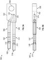
- FIG. 6A and FIG. 6B show an input terminal 600 that may comprise source supply connection 110 and source return connection 112 as shown in FIG. 1 and FIG. 2 .
- Input terminal 600 may be made of an electrically conductive material.
- input terminal 600 may comprise an input terminal tab 602, a first input terminal tube 604, and a second input terminal tube 606.
- Input terminal tab 602 may comprise an input terminal tab opening 608.
- First input terminal tube 604 may comprise a first input terminal tube port 610, a first plurality of first input terminal tube barbs 612, a second plurality of first input terminal tube barbs 614, a first input terminal tube first end 616, and a first input terminal tube second end 618.
- Second input terminal tube 606 may comprise a second input terminal tube port 620, a first plurality of second input terminal tube barbs 622, a second plurality of second input terminal tube barbs 624, a second input terminal tube first end 626, and a second input terminal tube second end 628.
- Input terminal 600 may comprise source supply connection 110. As described in greater detail below, input terminal 600 may be installed on supply conductor 118 of liquid cooled charging cable 106 at source end 142 of liquid cooled charging cable 106. A fastener (e.g., a bolt) may be placed through input terminal tab opening 608 in order to fasten input terminal tab 602 (source supply connection 110) to, for example, a positive lead of source 102. Similarly, input terminal 600 may comprise source return connection 112. As described in greater detail below, input terminal 600 may be installed on return conductor 120 of liquid cooled charging cable 106 at source end 142 of liquid cooled charging cable 106. A fastener (e.g., a bolt) may be placed through input terminal tab opening 608 in order to fasten input terminal tab 602 (as source return connection 112) to, for example, a negative lead of source 102.
- a fastener e.g., a bolt
- the coolant may cool output terminal tab 602.
- the coolant may enter first input terminal tube 604 at first input terminal tube port 610, pass through first input terminal tube 604, and exit first input terminal tube 604 at first input terminal tube second end 618.
- the coolant may enter second input terminal tube 606 at second input terminal tube port 620, pass through second input terminal tube 606, and exit second input terminal tube 606 at second input terminal tube second end 628. Consequently, the coolant may absorb heat from input terminal tab 602.
- cooling device 108, first cooling device 202, and second cooling device 204 may pump the coolant into liquid cooled charging cable 106, receive the coolant back from liquid cooled charging cable 106, remove heat from the coolant that was received back, and then re-pump the cooled coolant back into liquid cooled charging cable 106.
- the coolant may be pumped at 0.8 GPM with coolant temperature rise of 6.7 degrees C.
- the coolant may comprise a liquid that has a low conductivity and that is capable of cooling cable 106.
- the coolant may provide cable 106 with: i) a calculated leakage current of 18 micro-amps for 15 feet of cable 106 at 50 micro-Siemens; and ii) a calculated power loss at 350a of 1.498kw considering both supply conductor 118 and return conductor 120.
- the coolant may have a -35 degrees C freezing point, conductivity of 0.36 micro-Siemens per centimeter, and a life of 2 to 3 years.
- the coolant may comprise Koolance LIQ-705, manufactured by Koolance of 2840 W Valley Highway N, Auburn, WA 98001.
- cooling device 108, first cooling device 202, and second cooling device 204 may pump the coolant directly around a bare (e.g., no insulation, no covering, etc.) electrical conductor (e.g., first supply sub-conductor 316, second supply sub-conductor 318, first return sub-conductor 320, second return sub-conductor 322, supply conductor 420, and return conductor 422), into a input terminal 600 attached to the electrical conductor, and into output terminal 500 attached to the electrical conductor in order to cool these components.
- a bare electrical conductor e.g., first supply sub-conductor 316, second supply sub-conductor 318, first return sub-conductor 320, second return sub-conductor 322, supply conductor 420, and return conductor 422
- cooling of the electrical conductor, input terminal connector 600, and output terminal connector 500 by the coolant may limit thermal resistance in the electrical conductor, input terminal connector 600, and output terminal connector 500 associated with these components due to heating caused by
- the liquid coolant may be provided by either two independent isolated cooling devices (e.g., first cooling device 202 and second cooling device 204) or by one cooling device (e.g., cooling device 108) that has a sufficient liquid column length from the conductor (e.g., liquid cooled charging cable 106) to the cooling device or bifurcation point of the liquid coolant.
- the liquid column length along with an appropriate coolant conductivity may provide the required electrical isolation between a supply conductor (e.g., supply conductor 118) and a return conductor (e.g., load return connection 116) and either of these conductors to grounded cooling pumps (e.g., cooling device 108, first cooling device 202, and second cooling device 204).
- coolant supply conduit first section 130 may be connector to first input terminal tube second end 618 and over second plurality of first input terminal tube barbs 614 forming a watertight seal around first input terminal tube 604 at first input terminal tube second end 618.
- coolant return conduit first section 138 may be connector to second input terminal tube second end 628 and over second plurality of second input terminal tube barbs 624 forming a watertight seal around second input terminal tube 606 at second input terminal tube second end 628.
- Another input terminal 600 may be used as source return connection 112 on return conductor 120 at source end 142.
- coolant supply conduit second section 132 may be connector to first input terminal tube second end 618 and over second plurality of first input terminal tube barbs 614 forming a watertight seal around first input terminal tube 604 at first input terminal tube second end 618.
- coolant return conduit second section 140 may be connector to second input terminal tube second end 628 and over second plurality of second input terminal tube barbs 624 forming a watertight seal around second input terminal tube 606 at second input terminal tube second end 628.
- One input terminal 600 may be used as source supply connection 110 on supply conductor 118 at source end 142.
- first coolant supply conduit 206 may be connector to first input terminal tube second end 618 and over second plurality of first input terminal tube barbs 614 forming a watertight seal around first input terminal tube 604 at first input terminal tube second end 618.
- first coolant return conduit 208 may be connector to second input terminal tube second end 628 and over second plurality of second input terminal tube barbs 624 forming a watertight seal around second input terminal tube 606 at second input terminal tube second end 628.
- Another input terminal 600 may be used as source return connection 112 on return conductor 120 at source end 142.
- second coolant supply conduit 210 may be connector to first input terminal tube second end 618 and over second plurality of first input terminal tube barbs 614 forming a watertight seal around first input terminal tube 604 at first input terminal tube second end 618.
- second coolant return conduit 212 may be connector to second input terminal tube second end 628 and over second plurality of second input terminal tube barbs 624 forming a watertight seal around second input terminal tube 606 at second input terminal tube second end 628.
- Liquid Cooled Charging Cable 300 As Liquid Cooled Charging Cable 106
- first supply sub-conductor 316 may be crimped or otherwise electrically attached to first input terminal tube 604 at first input terminal tube first end 616. Consequently, first supply sub-conductor 316 may be in electrical connection with input terminal tab 602.
- First supply hose 304 may be pulled over first plurality of first input terminal tube barbs 612 forming a watertight seal around first input terminal tube first end 616.
- second supply sub-conductor 318 may be crimped or otherwise electrically attached to second input terminal tube 606 at second input terminal tube first end 626. Consequently, second supply sub-conductor 318 may be in electrical connection with input terminal tab 602.
- First return hose 306 may be pulled over first plurality of second input terminal tube barbs 622 forming a watertight seal around second input terminal tube first end 626.
- first supply sub-conductor 316 and second supply sub-conductor 318 may together function as two parallel conductors comprising supply conductor 118.
- first return sub-conductor 320 may be crimped or otherwise electrically attached to first input terminal tube 604 at first input terminal tube first end 616. Consequently, first return sub-conductor 320 may be in electrical connection with input terminal tab 602.
- Second supply hose 308 may be pulled over first plurality of first input terminal tube barbs 612 forming a watertight seal around first input terminal tube first end 616.
- second return sub-conductor 322 may be crimped or otherwise electrically attached to second input terminal tube 606 at second input terminal tube first end 626. Consequently, second return sub-conductor 322 may be in electrical connection with input terminal tab 602.
- Second return hose 310 may be pulled over first plurality of second input terminal tube barbs 622 forming a watertight seal around second input terminal tube first end 626.
- first return sub-conductor 320 and second return sub-conductor 322 may together function as two parallel conductors comprising return conductor 120.
- One output terminal 500 may be used as Load supply connection 114 on supply conductor 118 at load end 144.
- Another output terminal 500 may be used as load return connection 116 on return conductor 120 at load end 144.
- first supply sub-conductor 316 may be crimped or otherwise electrically attached to first output terminal tube 504 at first output terminal tube first end 514. Consequently, first supply sub-conductor 316 may be in electrical connection with output terminal tab 502.
- First supply hose 304 may be pulled over plurality of first output terminal tube barbs 512 forming a watertight seal around first output terminal tube first end 514.
- second supply sub-conductor 318 may be crimped or otherwise electrically attached to second output terminal tube 506 at second output terminal tube first end 522. Consequently, second supply sub-conductor 318 may be in electrical connection with output terminal tab 502.
- First return hose 306 may be pulled over plurality of second output terminal tube barbs 520 forming a watertight seal around second output terminal tube first end 522.
- first supply sub-conductor 316 and second supply sub-conductor 318 may together function as two parallel conductors comprising supply conductor 118.
- first return sub-conductor 320 may be crimped or otherwise electrically attached to first output terminal tube 504 at first output terminal tube first end 514. Consequently, first return sub-conductor 320 may be in electrical connection with output terminal tab 502.
- Second supply hose 308 may be pulled over plurality of first output terminal tube barbs 512 forming a watertight seal around first output terminal tube first end 514.
- second return sub-conductor 322 may be crimped or otherwise electrically attached to second output terminal tube 506 at second output terminal tube first end 522. Consequently, second return sub-conductor 322 may be in electrical connection with output terminal tab 502.
- Second return hose 310 may be pulled over plurality of second output terminal tube barbs 520 forming a watertight seal around second output terminal tube first end 522.
- first return sub-conductor 320 and second return sub-conductor 322 may together function as two parallel conductors comprising return conductor 120.
- the coolant may flow into the inside first input terminal tube 604 from first input terminal tube second end 618. Because first input terminal tube 604 is connected to input terminal tab 602, the coolant may cool input terminal tab 602. The coolant may then flow out of first input terminal tube port 610 and into first supply hose 304. The coolant may surround first supply sub-conductor 316 and flow the length of first supply hose 304 to load end 144. Because first supply sub-conductor 316 is immersed in the coolant, heat from first supply sub-conductor 316 may be transferred into the coolant.
- the coolant may flow into first output terminal tube 504 at first output terminal tube port 510 to first output terminal tube second end 516 and into second output terminal tube 506 at second output terminal tube second end 524. Because the coolant is in output terminal tab 502, the coolant may also cool output terminal tab 502. The coolant may flow out of second output terminal tube 506 at second output terminal tube port 518 and into first return hose 306. The coolant may flow the length of first return hose 306 back to source end 142. Because second supply sub-conductor 318 is immersed in the coolant, heat from second supply sub-conductor 318 may be transferred into the coolant. The coolant may flow into second input terminal tube 606 at second input terminal tube port 620.
- second input terminal tube 606 is connected to input terminal tab 602, the coolant may cool input terminal tab 602. The coolant may then flow out of second input terminal tube 606 at second input terminal tube second end 628 back to cooling device 108 (e.g., FIG. 1 configuration) or first cooling device 202 ( FIG. 2 configuration) to be cooled and reused.
- cooling device 108 e.g., FIG. 1 configuration
- first cooling device 202 FIG. 2 configuration
- the coolant may flow into the inside first input terminal tube 604 from first input terminal tube second end 618. Because first input terminal tube 604 is connected to input terminal tab 602, the coolant may cool input terminal tab 602. The coolant may then flow out of first input terminal tube port 610 and into second supply hose 308. The coolant may surround first return sub-conductor 320 and flow the length of second supply hose 308 to load end 144. Because first return sub-conductor 320 is immersed in the coolant, heat from first return sub-conductor 320 may be transferred into the coolant.
- the coolant may flow into first output terminal tube 504 at first output terminal tube port 510 to first output terminal tube second end 516 and into second output terminal tube 506 at second output terminal tube second end 524. Because the coolant is in output terminal tab 502, the coolant may also cool output terminal tab 502. The coolant may flow out of second output terminal tube 506 at second output terminal tube port 518 and into second return hose 310. The coolant may flow the length of second return hose 310 back to source end 142. Because second return sub-conductor 322 is immersed in the coolant, heat from second return sub-conductor 322 may be transferred into the coolant. The coolant may flow into second input terminal tube 606 at second input terminal tube port 620.
- second input terminal tube 606 is connected to input terminal tab 602, the coolant may cool input terminal tab 602. The coolant may then flow out of second input terminal tube 606 at second input terminal tube second end 628 back to cooling device 108 (e.g., FIG. 1 configuration) or first cooling device 202 ( FIG. 2 configuration) to be cooled and reused.
- cooling device 108 e.g., FIG. 1 configuration
- first cooling device 202 FIG. 2 configuration
- Liquid Cooled Charging Cable 400 As Liquid Cooled Charging Cable 106
- One input terminal 600 may be used as source supply connection 110 on supply conductor 118 at source end 142.
- Another input terminal 600 may be used as source return connection 112 on return conductor 120 at source end 142.
- supply conductor 420 may be crimped or otherwise electrically attached to first input terminal tube 604 at first input terminal tube first end 616. Consequently, supply conductor 420 may be in electrical connection with input terminal tab 602. First supply hose 404 may be pulled over first plurality of first input terminal tube barbs 612 forming a watertight seal around first input terminal tube first end 616. Then, first return hose 406 may be pulled over first plurality of second input terminal tube barbs 622 forming a watertight seal around second input terminal tube first end 626. In this embodiment, supply conductor 420 may function as supply conductor 118.
- return conductor 422 may be crimped or otherwise electrically attached to first input terminal tube 604 at first input terminal tube first end 616. Consequently, first return sub-conductor 320 may be in electrical connection with input terminal tab 602. Second supply hose 408 may be pulled over first plurality of first input terminal tube barbs 612 forming a watertight seal around first input terminal tube first end 616. Then second return hose 410 may be pulled over first plurality of second input terminal tube barbs 622 forming a watertight seal around second input terminal tube first end 626. In this embodiment, return conductor 422 may function as return conductor 120.
- One output terminal 500 may be used as load supply connection 114 on supply conductor 118 at load end 144.
- Another output terminal 500 may be used as load return connection 116 on return conductor 120 at load end 144.
- supply conductor 420 may be crimped or otherwise electrically attached to first output terminal tube 504 at first output terminal tube first end 514. Consequently, supply conductor 420 may be in electrical connection with output terminal tab 502. First supply hose 404 may be pulled over plurality of first output terminal tube barbs 512 forming a watertight seal around first output terminal tube first end 514. Then first return hose 406 may be pulled over plurality of second output terminal tube barbs 520 forming a watertight seal around second output terminal tube first end 522. In this embodiment, supply conductor 420 may function as supply conductor 118.
- return conductor 422 may be crimped or otherwise electrically attached to first output terminal tube 504 at first output terminal tube first end 514. Consequently, return conductor 422 may be in electrical connection with output terminal tab 502. Second supply hose 408 may be pulled over plurality of first output terminal tube barbs 512 forming a watertight seal around first output terminal tube first end 514. Then second return hose 410 may be pulled over plurality of second output terminal tube barbs 520 forming a watertight seal around second output terminal tube first end 522. In this embodiment, return conductor 422 may function as return conductor 120.
- the coolant may flow into the inside first input terminal tube 604 from first input terminal tube second end 618. Because first input terminal tube 604 is connected to input terminal tab 602, the coolant may cool input terminal tab 602. The coolant may then flow out of first input terminal tube port 610 and into first supply hose 404. The coolant may surround supply conductor 420 and flow the length of first supply hose 404 to load end 144. Because supply conductor 420 is immersed in the coolant, heat from supply conductor 420 may be transferred into the coolant. At load end 144, the coolant may flow into first output terminal tube 504 at first output terminal tube port 510 to first output terminal tube second end 516 and into second output terminal tube 506 at second output terminal tube second end 524.
- the coolant may also cool output terminal tab 502.
- the coolant may flow out of second output terminal tube 506 at second output terminal tube port 518 and into first return hose 406.
- the coolant may flow the length of first return hose 406 back to source end 142.
- the coolant may flow into second input terminal tube 606 at second input terminal tube port 620.
- second input terminal tube 606 is connected to input terminal tab 602, the coolant may cool input terminal tab 602.
- the coolant may then flow out of second input terminal tube 606 at second input terminal tube second end 628 back to cooling device 108 (e.g., FIG. 1 configuration) or first cooling device 202 ( FIG. 2 configuration) to be cooled and reused.
- the coolant may flow into the inside first input terminal tube 604 from first input terminal tube second end 618. Because first input terminal tube 604 is connected to input terminal tab 602, the coolant may cool input terminal tab 602. The coolant may then flow out of first input terminal tube port 610 and into second supply hose 408. The coolant may surround return conductor 422 and flow the length of second supply hose 408 to load end 144. Because return conductor 422 is immersed in the coolant, heat from return conductor 422 may be transferred into the coolant. At load end 144, the coolant may flow into first output terminal tube 504 at first output terminal tube port 510 to first output terminal tube second end 516 and into second output terminal tube 506 at second output terminal tube second end 524.
- the coolant may also cool output terminal tab 502.
- the coolant may flow out of second output terminal tube 506 at second output terminal tube port 518 and into second return hose 410.
- the coolant may flow the length of second return hose 410 back to source end 142.
- the coolant may flow into second input terminal tube 606 at second input terminal tube port 620.
- second input terminal tube 606 is connected to input terminal tab 602, the coolant may cool input terminal tab 602.
- the coolant may then flow out of second input terminal tube 606 at second input terminal tube second end 628 back to cooling device 108 (e.g., FIG. 1 configuration) or first cooling device 202 ( FIG. 2 configuration) to be cooled and reused.
- Embodiments of the present disclosure are described above with reference to block diagrams and/or operational illustrations of methods, systems, and computer program products according to embodiments of the disclosure.
- the functions/acts noted in the blocks may occur out of the order as shown in any flowchart.
- two blocks shown in succession may in fact be executed substantially concurrently or the blocks may sometimes be executed in the reverse order, depending upon the functionality/acts involved.
Landscapes
- Engineering & Computer Science (AREA)
- Power Engineering (AREA)
- Transportation (AREA)
- Mechanical Engineering (AREA)
- Sustainable Energy (AREA)
- Sustainable Development (AREA)
- Life Sciences & Earth Sciences (AREA)
- Electric Propulsion And Braking For Vehicles (AREA)
- Insulated Conductors (AREA)
- Cooling Or The Like Of Electrical Apparatus (AREA)
- Gas Or Oil Filled Cable Accessories (AREA)
- Laying Of Electric Cables Or Lines Outside (AREA)
- Charge And Discharge Circuits For Batteries Or The Like (AREA)
Description
- An electric vehicle (EV) charging system, also called an electric recharging point, a charging point, a charging station a charge point, and an EVSE (Electric Vehicle Supply Equipment), is an element in an infrastructure that supplies electric energy for recharging electric vehicles, such as plug-in electric vehicles, including electric cars, neighborhood electric vehicles, and plug-in hybrids. Because plug-in hybrid electric vehicles and battery electric vehicle ownership is expanding, there is a growing need for widely distributed publicly accessible charging stations, some of which support faster charging at higher voltages and currents than are available from residential EVSEs. Many charging stations are on-street facilities provided by electric utility companies or located at retail shopping centers and operated by private companies. These charging stations provide one or a range of heavy duty or special connectors that conform to the variety of electric charging connector standards.
- An example for the prior art can be found in
US 2015/217654 A1 disclosing a liquid cooled cabel for a electric vehicle charging station. - The accompanying drawings, which are incorporated in and constitute a part of this disclosure, illustrate various embodiments of the present disclosure. In the drawings:
-
FIG. 1 shows a liquid cooled charging system; -
FIG. 2 shows a liquid cooled charging system; -
FIG. 3 shows a liquid cooled charging cable; -
FIG. 4 shows a liquid cooled charging cable; -
FIG. 5A and FIG. 5B show an output terminal; and -
FIG. 6A and FIG. 6B show an input terminal. - A liquid cooled charging cable system may be provided. The liquid cooled charging cable system may comprise a source, a load, a liquid cooled charging cable, and a cooling device. The liquid cooled charging cable may connect the source to the load, and may supply electric energy from the source to the load. The liquid cooled charging cable may comprise a supply conductor and a return conductor. The cooling device may pump a coolant around the supply conductor and the return conductor where the supply conductor and the return conductor may be immersed in the coolant.
- Both the foregoing overview and the following example embodiments are examples and explanatory only, and should not be considered to restrict the disclosure's scope, as described and claimed. Further, features and/or variations may be provided in addition to those set forth herein. For example, embodiments of the disclosure may be directed to various feature combinations and sub-combinations described in the example embodiments.
- The following detailed description refers to the accompanying drawings. Wherever possible, the same reference numbers are used in the drawings and the following description to refer to the same or similar elements. While embodiments of the disclosure may be described, modifications, adaptations, and other implementations are possible. For example, substitutions, additions, or modifications may be made to the elements illustrated in the drawings, and the methods described herein may be modified by substituting, reordering, or adding stages to the disclosed methods. Accordingly, the following detailed description does not limit the disclosure. Instead, the proper scope of the disclosure is defined by the appended claims.
- A charging system may be used to charge a battery or batteries, for example, an electric vehicle's batteries. Consistent with embodiments of the disclosure, electric vehicles may comprise, but are not limited to, electric cars, neighborhood electric vehicles, fork lifts, plug-in hybrids, etc. When batteries are charged, the time required to charge the batteries may be governed by the amount of current that a charging system can deliver to the batteries. One of the limiting factors for increasing the amount of charge current to the batteries and therefore reducing the amount of charge time may be the cable that connects an electric power source to the batteries.
- Conventional systems may use an air cooled charging cable in battery charging applications, for example, in applications where the charging current is below 200A. As the electric charging current increases above 200A, the corresponding required size of the charging cable used to charge the batteries may become too large, too heavy, and too inflexible for a consumer to use. Consistent with embodiments of the disclosure, a liquid cooled charging cable may be provided. The liquid cooled charging cable may supply currents (e.g., 400A to 1,000A) that may be 2 to 5 times as much as the currents supplied by the conventional air cooled charging cable, but unlike the conventional air cooled charging cable, in a size, weight, and flexibility suitable for a consumer to use. Conventional liquid cooled charging cables electrically isolate the cooling liquid from metallic conductor components to prevent shorts between conductors or to ground through the liquid. The conventional approach limits the benefit of liquid cooling by adding a thermally insulating layer between the conductor and the cooling liquid.
- Consistent with embodiments of the disclosure, liquid coolant from a cooling device may be pumped directly around an electrical conductor (e.g., bare, uninsulated) and into an input terminal connector and an output terminal connector attached to the electrical conductor in order to cool these components. Accordingly, cooling of the electrical conductor, the input terminal connector, and the output terminal connector by the coolant may greatly limit thermal resistance in the electrical conductor, the input terminal connector, and the output terminal connector associated with these components due to heating caused by high electrical currents in the these components.
- The liquid coolant maybe provided by either two independent isolated cooling devices or by one cooling device that has a sufficient liquid column length from the conductor to the cooling device or bifurcation point of the liquid coolant. The liquid column length along with an appropriate coolant conductivity may provide the required electrical isolation between a supply conductor and a return conductor and either of these conductors to grounded cooling pumps or associated hardware.
-
FIG. 1 shows a liquid cooledcharging system 100 consistent with embodiments of the disclosure. As shown inFIG. 1 , liquid cooledcharging system 100 may comprise asource 102, aload 104, a liquid cooledcharging cable 106, and acooling device 108.Source 102 may connect to liquid cooledcharging cable 106 via asource supply connection 110 and asource return connection 112.Load 104 may connect to liquid cooledcharging cable 106 via aload supply connection 114 and aload return connection 116. Liquid cooledcharging cable 106 may comprise asupply conductor 118 and areturn conductor 120.Source 102 may comprise a power supply capable of chargingload 104 comprising an energy storage device, for example, a battery or bank of batteries. - Coolant may be provided to both
supply conductor 118 andreturn conductor 120 of liquid cooledcharging cable 106 bycooling device 108 viacoolant supply conduit 122 andcoolant return conduit 124.Supply conduit 122 andcoolant return conduit 124 may be made from electrically non-conductive material and may have sufficient length to minimize the leakage current to ground or betweensupply conductor 118 andreturn conductor 120.Coolant supply conduit 122 may comprise a coolant supply conduitmain section 126, a coolant supplyconduit bifurcation point 128, a coolant supply conduitfirst section 130, and a coolant supply conduitsecond section 132.Coolant return conduit 124 may comprise a coolant return conduitmain section 134, a coolant returnconduit bifurcation point 136, a coolant return conduitfirst section 138, and a coolant return conduitsecond section 140. -
Source 102 may connect to liquid cooledcharging cable 106 viasource supply connection 110 and asource return connection 112 at asource end 142 of liquid cooledcharging cable 106.Load 104 may connect to liquid cooledcharging cable 106 via aload supply connection 114 and aload return connection 116 at aload end 144 of liquid cooledcharging cable 106. The coolant may be supplied fromcoolant supply conduit 122 and returned tocoolant return conduit 124 atsource end 142 of liquid cooledcharging cable 106. -
Cooling device 108 may pump the coolant into coolant supply conduitmain section 126. The coolant by then feed into both coolant supply conduitfirst section 130 and coolant supply conduitsecond section 132 at coolant supplyconduit bifurcation point 128. Coolant supply conduitfirst section 130 may feed coolant to supplyconductor 118 of liquid cooledcharging cable 106. Coolant supply conduitsecond section 132 may feed coolant to returnconductor 120 of liquid cooled chargingcable 106. The coolant may circulate through liquid cooled chargingcable 106. A portion of the coolant may return into coolant return conduitfirst section 138 and a portion of the coolant may return into coolant return conduitsecond section 140. The returned coolant may come together at coolant returnconduit bifurcation point 136 into coolant return conduitmain section 134 and back intocooling device 108.Cooling device 108 may cool the returned coolant that may have absorbed heat from liquid cooled chargingcable 106.Cooling device 108 may reuse the returned coolant by pumping it back into coolant supply conduitmain section 126. -
FIG. 2 shows a liquid cooled chargingsystem 200 consistent with embodiments of the disclosure. Liquid cooled chargingsystem 200 may be similar to liquid cooled chargingsystem 100; however, liquid cooled chargingsystem 200 may comprise two cooling devices rather than one cooling device. As shown inFIG. 2 , liquid cooled chargingsystem 200 may comprise afirst cooling device 202 and asecond cooling device 204. Coolant may be provided to supplyconductor 118 of liquid cooled chargingcable 106 byfirst cooling device 202 via a firstcoolant supply conduit 206 and returned fromsupply conductor 118 tofirst cooling device 202 via a firstcoolant return conduit 208. Similarly, coolant may be provided to returnconductor 120 of liquid cooled chargingcable 106 bysecond cooling device 204 via a secondcoolant supply conduit 210 and returned fromreturn conductor 120 tosecond cooling device 204 via a secondcoolant return conduit 212. The conduits (e.g., firstcoolant supply conduit 206, firstcoolant return conduit 208, secondcoolant supply conduit 210, and second coolant return conduit 212) may be made from electrically non-conductive material and have sufficient length to minimize the leakage current to ground or betweensupply conductor 118 and returnconductor 120. -
FIG. 3 shows a cross-section of a liquid cooled chargingcable 300. Liquid cooled chargingcable 300 may comprise liquid cooled chargingcable 106 as described above with respect toFIG.1 and FIG. 2 . As shown inFIG. 3 , liquid cooled chargingcable 300 may comprise ajacket 302.Jacket 302 may comprise afirst supply hose 304, afirst return hose 306, asecond supply hose 308, asecond return hose 310, apilot cable 312, and aground wire 314.First supply hose 304 may comprise afirst supply sub-conductor 316,first return hose 306 may comprise asecond supply sub-conductor 318,second supply hose 308 may comprise afirst return sub-conductor 320, andsecond return hose 310 may comprise asecond return sub-conductor 322.Pilot cable 312 may comprise afirst pilot wire 324, asecond pilot wire 326, and athird pilot wire 328. -
FIG. 4 shows a cross-section of a liquid cooled chargingcable 400. Liquid cooled chargingcable 400 may comprise liquid cooled chargingcable 106 as described above with respect toFIG.1 and FIG. 2 . As shown inFIG. 4 , liquid cooled chargingcable 400 may comprise ajacket 402.Jacket 402 may contain afirst supply hose 404, afirst return hose 406, asecond supply hose 408, and asecond return hose 410. In addition,jacket 402 may contain afirst pilot wire 412, asecond pilot wire 414, athird pilot wire 416, and aground wire 418.First supply hose 404 may comprise asupply conductor 420 andsecond supply hose 408 may comprise areturn conductor 422. - Pilot cable 312 (i.e.,
first pilot wire 324,second pilot wire 326, and third pilot wire 328) ofFIG. 3 may be used to send control signals or supply power to elements located atsource 102 andload 104. Similarly,first pilot wire 412,second pilot wire 414, andthird pilot wire 416 ofFIG. 4 may be used to send control signals or supply power to elements located atsource 102 andload 104. The pilot wires may be located at the center of liquid cooled chargingcable 300 aspilot cable 312 as shown inFIG. 3 or the pilot wires may be located individually at any location withinjacket 402 as shown inFIG. 4 aspilot wire 412,second pilot wire 414, andthird pilot wire 416. Embodiments of the disclosure may comprise any number of pilot wires and is not limited to three.Ground wire 314 of liquid cooled chargingcable 300 andground wire 418 of liquid cooled chargingcable 400 may be used to connectsource 102 and load 104 and maintain them at a common ground. -
FIG. 5A and FIG. 5B show anoutput terminal 500 that may compriseload supply connection 114 and loadreturn connection 116 as shown inFIG. 1 and FIG. 2 .Output terminal 500 may be made of an electrically conductive material. As shown inFIG. 5A and FIG. 5B ,output terminal 500 may comprise anoutput terminal tab 502, a firstoutput terminal tube 504, and a secondoutput terminal tube 506.Output terminal tab 502 may comprise an outputterminal tab opening 508. Firstoutput terminal tube 504 may comprise a first outputterminal tube port 510, a plurality of first outputterminal tube barbs 512, a first output terminal tubefirst end 514, and a first output terminal tubesecond end 516. Secondoutput terminal tube 506 may comprise a second outputterminal tube port 518, a plurality of second outputterminal tube barbs 520, a second output terminal tubefirst end 522, and a second output terminal tubesecond end 524. -
Output terminal 500 may compriseload supply connection 114. As described in greater detail below,output terminal 500 may be installed onsupply conductor 118 of liquid cooled chargingcable 106 atload end 144 of liquid cooled chargingcable 106. A fastener (e.g., a bolt) may be placed through output terminal tab opening 508 in order to fasten output terminal tab 502 (load supply connection 114) to, for example, a positive lead ofload 104. Similarly,output terminal 500 may compriseload return connection 116. As described in greater detail below,output terminal 500 may be installed onreturn conductor 120 of liquid cooled chargingcable 106 atload end 144 of liquid cooled chargingcable 106. A fastener (e.g., a bolt) may be placed through output terminal tab opening 508 in order to fasten output terminal tab 502 (as load return connection 116) to, for example, a negative lead ofload 104. - Consistent with embodiments of the disclosure, the coolant may cool
output terminal tab 502. The coolant may enter firstoutput terminal tube 504 at first outputterminal tube port 510, pass through firstoutput terminal tube 504 to first output terminal tubesecond end 516, enter secondoutput terminal tube 506 at second output terminal tubesecond end 524, and exit secondoutput terminal tube 506 at second outputterminal tube port 518. Consequently, the coolant may absorb heat fromoutput terminal tab 502. Consistent with embodiments of the disclosure, the coolant may flow in an opposite direction entering second outputterminal tube port 518 and exiting first outputterminal tube port 510. -
FIG. 6A and FIG. 6B show aninput terminal 600 that may comprisesource supply connection 110 and source returnconnection 112 as shown inFIG. 1 and FIG. 2 .Input terminal 600 may be made of an electrically conductive material. As shown inFIG. 6A and FIG. 6B ,input terminal 600 may comprise aninput terminal tab 602, a firstinput terminal tube 604, and a secondinput terminal tube 606.Input terminal tab 602 may comprise an inputterminal tab opening 608. Firstinput terminal tube 604 may comprise a first inputterminal tube port 610, a first plurality of first inputterminal tube barbs 612, a second plurality of first inputterminal tube barbs 614, a first input terminal tubefirst end 616, and a first input terminal tubesecond end 618. Secondinput terminal tube 606 may comprise a second inputterminal tube port 620, a first plurality of second inputterminal tube barbs 622, a second plurality of second inputterminal tube barbs 624, a second input terminal tubefirst end 626, and a second input terminal tubesecond end 628. -
Input terminal 600 may comprisesource supply connection 110. As described in greater detail below,input terminal 600 may be installed onsupply conductor 118 of liquid cooled chargingcable 106 at source end 142 of liquid cooled chargingcable 106. A fastener (e.g., a bolt) may be placed through input terminal tab opening 608 in order to fasten input terminal tab 602 (source supply connection 110) to, for example, a positive lead ofsource 102. Similarly,input terminal 600 may comprisesource return connection 112. As described in greater detail below,input terminal 600 may be installed onreturn conductor 120 of liquid cooled chargingcable 106 at source end 142 of liquid cooled chargingcable 106. A fastener (e.g., a bolt) may be placed through input terminal tab opening 608 in order to fasten input terminal tab 602 (as source return connection 112) to, for example, a negative lead ofsource 102. - Consistent with embodiments of the disclosure, the coolant may cool
output terminal tab 602. The coolant may enter firstinput terminal tube 604 at first inputterminal tube port 610, pass through firstinput terminal tube 604, and exit firstinput terminal tube 604 at first input terminal tubesecond end 618. Similarly, the coolant may enter secondinput terminal tube 606 at second inputterminal tube port 620, pass through secondinput terminal tube 606, and exit secondinput terminal tube 606 at second input terminal tubesecond end 628. Consequently, the coolant may absorb heat frominput terminal tab 602. - Consistent with embodiments of the disclosure,
cooling device 108,first cooling device 202, andsecond cooling device 204 may pump the coolant into liquid cooled chargingcable 106, receive the coolant back from liquid cooled chargingcable 106, remove heat from the coolant that was received back, and then re-pump the cooled coolant back into liquid cooled chargingcable 106. The coolant may be pumped at 0.8 GPM with coolant temperature rise of 6.7 degrees C. - The coolant may comprise a liquid that has a low conductivity and that is capable of cooling
cable 106. For example, the coolant may providecable 106 with: i) a calculated leakage current of 18 micro-amps for 15 feet ofcable 106 at 50 micro-Siemens; and ii) a calculated power loss at 350a of 1.498kw considering bothsupply conductor 118 and returnconductor 120. The coolant may have a -35 degrees C freezing point, conductivity of 0.36 micro-Siemens per centimeter, and a life of 2 to 3 years. The coolant may comprise Koolance LIQ-705, manufactured by Koolance of 2840 W Valley Hwy N, Auburn, WA 98001. - Consistent with embodiments of the disclosure,
cooling device 108,first cooling device 202, andsecond cooling device 204 may pump the coolant directly around a bare (e.g., no insulation, no covering, etc.) electrical conductor (e.g.,first supply sub-conductor 316,second supply sub-conductor 318,first return sub-conductor 320,second return sub-conductor 322,supply conductor 420, and return conductor 422), into ainput terminal 600 attached to the electrical conductor, and intooutput terminal 500 attached to the electrical conductor in order to cool these components. Accordingly, cooling of the electrical conductor,input terminal connector 600, andoutput terminal connector 500 by the coolant may limit thermal resistance in the electrical conductor,input terminal connector 600, andoutput terminal connector 500 associated with these components due to heating caused by high electrical currents in the these components. - The liquid coolant may be provided by either two independent isolated cooling devices (e.g.,
first cooling device 202 and second cooling device 204) or by one cooling device (e.g., cooling device 108) that has a sufficient liquid column length from the conductor (e.g., liquid cooled charging cable 106) to the cooling device or bifurcation point of the liquid coolant. The liquid column length along with an appropriate coolant conductivity may provide the required electrical isolation between a supply conductor (e.g., supply conductor 118) and a return conductor (e.g., load return connection 116) and either of these conductors to grounded cooling pumps (e.g.,cooling device 108,first cooling device 202, and second cooling device 204). - One
input terminal 600 may be used assource supply connection 110 onsupply conductor 118 atsource end 142. For the configuration shown inFIG. 1 , coolant supply conduitfirst section 130 may be connector to first input terminal tubesecond end 618 and over second plurality of first inputterminal tube barbs 614 forming a watertight seal around firstinput terminal tube 604 at first input terminal tubesecond end 618. Also, coolant return conduitfirst section 138 may be connector to second input terminal tubesecond end 628 and over second plurality of second inputterminal tube barbs 624 forming a watertight seal around secondinput terminal tube 606 at second input terminal tubesecond end 628. - Another
input terminal 600 may be used assource return connection 112 onreturn conductor 120 atsource end 142. For the configuration shown inFIG. 1 , coolant supply conduitsecond section 132 may be connector to first input terminal tubesecond end 618 and over second plurality of first inputterminal tube barbs 614 forming a watertight seal around firstinput terminal tube 604 at first input terminal tubesecond end 618. Also, coolant return conduitsecond section 140 may be connector to second input terminal tubesecond end 628 and over second plurality of second inputterminal tube barbs 624 forming a watertight seal around secondinput terminal tube 606 at second input terminal tubesecond end 628. - One
input terminal 600 may be used assource supply connection 110 onsupply conductor 118 atsource end 142. For the configuration shown inFIG. 2 , firstcoolant supply conduit 206 may be connector to first input terminal tubesecond end 618 and over second plurality of first inputterminal tube barbs 614 forming a watertight seal around firstinput terminal tube 604 at first input terminal tubesecond end 618. Also, firstcoolant return conduit 208 may be connector to second input terminal tubesecond end 628 and over second plurality of second inputterminal tube barbs 624 forming a watertight seal around secondinput terminal tube 606 at second input terminal tubesecond end 628. - Another
input terminal 600 may be used assource return connection 112 onreturn conductor 120 atsource end 142. For the configuration shown inFIG. 2 , secondcoolant supply conduit 210 may be connector to first input terminal tubesecond end 618 and over second plurality of first inputterminal tube barbs 614 forming a watertight seal around firstinput terminal tube 604 at first input terminal tubesecond end 618. Also, secondcoolant return conduit 212 may be connector to second input terminal tubesecond end 628 and over second plurality of second inputterminal tube barbs 624 forming a watertight seal around secondinput terminal tube 606 at second input terminal tubesecond end 628. - At source end 142 of liquid cooled charging
cable 106, regarding liquid cooled chargingcable 300 as liquid cooled chargingcable 106,first supply sub-conductor 316 may be crimped or otherwise electrically attached to firstinput terminal tube 604 at first input terminal tubefirst end 616. Consequently,first supply sub-conductor 316 may be in electrical connection withinput terminal tab 602.First supply hose 304 may be pulled over first plurality of first inputterminal tube barbs 612 forming a watertight seal around first input terminal tubefirst end 616. Similarly,second supply sub-conductor 318 may be crimped or otherwise electrically attached to secondinput terminal tube 606 at second input terminal tubefirst end 626. Consequently,second supply sub-conductor 318 may be in electrical connection withinput terminal tab 602.First return hose 306 may be pulled over first plurality of second inputterminal tube barbs 622 forming a watertight seal around second input terminal tubefirst end 626. In this embodiment,first supply sub-conductor 316 andsecond supply sub-conductor 318 may together function as two parallel conductors comprisingsupply conductor 118. - At source end 142 of liquid cooled charging
cable 106, regarding liquid cooled chargingcable 300 as liquid cooled chargingcable 106,first return sub-conductor 320 may be crimped or otherwise electrically attached to firstinput terminal tube 604 at first input terminal tubefirst end 616. Consequently, first return sub-conductor 320 may be in electrical connection withinput terminal tab 602.Second supply hose 308 may be pulled over first plurality of first inputterminal tube barbs 612 forming a watertight seal around first input terminal tubefirst end 616. Similarly, second return sub-conductor 322 may be crimped or otherwise electrically attached to secondinput terminal tube 606 at second input terminal tubefirst end 626. Consequently, second return sub-conductor 322 may be in electrical connection withinput terminal tab 602.Second return hose 310 may be pulled over first plurality of second inputterminal tube barbs 622 forming a watertight seal around second input terminal tubefirst end 626. In this embodiment,first return sub-conductor 320 andsecond return sub-conductor 322 may together function as two parallel conductors comprisingreturn conductor 120. - One
output terminal 500 may be used asLoad supply connection 114 onsupply conductor 118 atload end 144. Anotheroutput terminal 500 may be used asload return connection 116 onreturn conductor 120 atload end 144. - At
load end 144 of liquid cooled chargingcable 106,first supply sub-conductor 316 may be crimped or otherwise electrically attached to firstoutput terminal tube 504 at first output terminal tubefirst end 514. Consequently,first supply sub-conductor 316 may be in electrical connection withoutput terminal tab 502.First supply hose 304 may be pulled over plurality of first outputterminal tube barbs 512 forming a watertight seal around first output terminal tubefirst end 514. Similarly,second supply sub-conductor 318 may be crimped or otherwise electrically attached to secondoutput terminal tube 506 at second output terminal tubefirst end 522. Consequently,second supply sub-conductor 318 may be in electrical connection withoutput terminal tab 502.First return hose 306 may be pulled over plurality of second outputterminal tube barbs 520 forming a watertight seal around second output terminal tubefirst end 522. In this embodiment,first supply sub-conductor 316 andsecond supply sub-conductor 318 may together function as two parallel conductors comprisingsupply conductor 118. - At
load end 144 of liquid cooled chargingcable 106,first return sub-conductor 320 may be crimped or otherwise electrically attached to firstoutput terminal tube 504 at first output terminal tubefirst end 514. Consequently, first return sub-conductor 320 may be in electrical connection withoutput terminal tab 502.Second supply hose 308 may be pulled over plurality of first outputterminal tube barbs 512 forming a watertight seal around first output terminal tubefirst end 514. Similarly, second return sub-conductor 322 may be crimped or otherwise electrically attached to secondoutput terminal tube 506 at second output terminal tubefirst end 522. Consequently, second return sub-conductor 322 may be in electrical connection withoutput terminal tab 502.Second return hose 310 may be pulled over plurality of second outputterminal tube barbs 520 forming a watertight seal around second output terminal tubefirst end 522. In this embodiment,first return sub-conductor 320 andsecond return sub-conductor 322 may together function as two parallel conductors comprisingreturn conductor 120. - For
supply conductor 118, the coolant may flow into the inside firstinput terminal tube 604 from first input terminal tubesecond end 618. Because firstinput terminal tube 604 is connected to inputterminal tab 602, the coolant may cool inputterminal tab 602. The coolant may then flow out of first inputterminal tube port 610 and intofirst supply hose 304. The coolant may surroundfirst supply sub-conductor 316 and flow the length offirst supply hose 304 to loadend 144. Becausefirst supply sub-conductor 316 is immersed in the coolant, heat fromfirst supply sub-conductor 316 may be transferred into the coolant. Atload end 144, the coolant may flow into firstoutput terminal tube 504 at first outputterminal tube port 510 to first output terminal tubesecond end 516 and into secondoutput terminal tube 506 at second output terminal tubesecond end 524. Because the coolant is inoutput terminal tab 502, the coolant may also cooloutput terminal tab 502. The coolant may flow out of secondoutput terminal tube 506 at second outputterminal tube port 518 and intofirst return hose 306. The coolant may flow the length offirst return hose 306 back to source end 142. Becausesecond supply sub-conductor 318 is immersed in the coolant, heat fromsecond supply sub-conductor 318 may be transferred into the coolant. The coolant may flow into secondinput terminal tube 606 at second inputterminal tube port 620. Because secondinput terminal tube 606 is connected to inputterminal tab 602, the coolant may cool inputterminal tab 602. The coolant may then flow out of secondinput terminal tube 606 at second input terminal tubesecond end 628 back to cooling device 108 (e.g.,FIG. 1 configuration) or first cooling device 202 (FIG. 2 configuration) to be cooled and reused. - For
return conductor 120, the coolant may flow into the inside firstinput terminal tube 604 from first input terminal tubesecond end 618. Because firstinput terminal tube 604 is connected to inputterminal tab 602, the coolant may cool inputterminal tab 602. The coolant may then flow out of first inputterminal tube port 610 and intosecond supply hose 308. The coolant may surround first return sub-conductor 320 and flow the length ofsecond supply hose 308 to loadend 144. Becausefirst return sub-conductor 320 is immersed in the coolant, heat fromfirst return sub-conductor 320 may be transferred into the coolant. Atload end 144, the coolant may flow into firstoutput terminal tube 504 at first outputterminal tube port 510 to first output terminal tubesecond end 516 and into secondoutput terminal tube 506 at second output terminal tubesecond end 524. Because the coolant is inoutput terminal tab 502, the coolant may also cooloutput terminal tab 502. The coolant may flow out of secondoutput terminal tube 506 at second outputterminal tube port 518 and intosecond return hose 310. The coolant may flow the length ofsecond return hose 310 back to source end 142. Becausesecond return sub-conductor 322 is immersed in the coolant, heat fromsecond return sub-conductor 322 may be transferred into the coolant. The coolant may flow into secondinput terminal tube 606 at second inputterminal tube port 620. Because secondinput terminal tube 606 is connected to inputterminal tab 602, the coolant may cool inputterminal tab 602. The coolant may then flow out of secondinput terminal tube 606 at second input terminal tubesecond end 628 back to cooling device 108 (e.g.,FIG. 1 configuration) or first cooling device 202 (FIG. 2 configuration) to be cooled and reused. - One
input terminal 600 may be used assource supply connection 110 onsupply conductor 118 atsource end 142. Anotherinput terminal 600 may be used assource return connection 112 onreturn conductor 120 atsource end 142. - At source end 142 of liquid cooled charging
cable 106, regarding liquid cooled chargingcable 400 as liquid cooled chargingcable 106,supply conductor 420 may be crimped or otherwise electrically attached to firstinput terminal tube 604 at first input terminal tubefirst end 616. Consequently,supply conductor 420 may be in electrical connection withinput terminal tab 602.First supply hose 404 may be pulled over first plurality of first inputterminal tube barbs 612 forming a watertight seal around first input terminal tubefirst end 616. Then,first return hose 406 may be pulled over first plurality of second inputterminal tube barbs 622 forming a watertight seal around second input terminal tubefirst end 626. In this embodiment,supply conductor 420 may function assupply conductor 118. - At source end 142 of liquid cooled charging
cable 106, regarding liquid cooled chargingcable 400 as liquid cooled chargingcable 106,return conductor 422 may be crimped or otherwise electrically attached to firstinput terminal tube 604 at first input terminal tubefirst end 616. Consequently, first return sub-conductor 320 may be in electrical connection withinput terminal tab 602.Second supply hose 408 may be pulled over first plurality of first inputterminal tube barbs 612 forming a watertight seal around first input terminal tubefirst end 616. Thensecond return hose 410 may be pulled over first plurality of second inputterminal tube barbs 622 forming a watertight seal around second input terminal tubefirst end 626. In this embodiment,return conductor 422 may function asreturn conductor 120. - One
output terminal 500 may be used asload supply connection 114 onsupply conductor 118 atload end 144. Anotheroutput terminal 500 may be used asload return connection 116 onreturn conductor 120 atload end 144. - At
load end 144 of liquid cooled chargingcable 106,supply conductor 420 may be crimped or otherwise electrically attached to firstoutput terminal tube 504 at first output terminal tubefirst end 514. Consequently,supply conductor 420 may be in electrical connection withoutput terminal tab 502.First supply hose 404 may be pulled over plurality of first outputterminal tube barbs 512 forming a watertight seal around first output terminal tubefirst end 514. Thenfirst return hose 406 may be pulled over plurality of second outputterminal tube barbs 520 forming a watertight seal around second output terminal tubefirst end 522. In this embodiment,supply conductor 420 may function assupply conductor 118. - At
load end 144 of liquid cooled chargingcable 106,return conductor 422 may be crimped or otherwise electrically attached to firstoutput terminal tube 504 at first output terminal tubefirst end 514. Consequently,return conductor 422 may be in electrical connection withoutput terminal tab 502.Second supply hose 408 may be pulled over plurality of first outputterminal tube barbs 512 forming a watertight seal around first output terminal tubefirst end 514. Thensecond return hose 410 may be pulled over plurality of second outputterminal tube barbs 520 forming a watertight seal around second output terminal tubefirst end 522. In this embodiment,return conductor 422 may function asreturn conductor 120. - For
supply conductor 118, the coolant may flow into the inside firstinput terminal tube 604 from first input terminal tubesecond end 618. Because firstinput terminal tube 604 is connected to inputterminal tab 602, the coolant may cool inputterminal tab 602. The coolant may then flow out of first inputterminal tube port 610 and intofirst supply hose 404. The coolant may surroundsupply conductor 420 and flow the length offirst supply hose 404 to loadend 144. Becausesupply conductor 420 is immersed in the coolant, heat fromsupply conductor 420 may be transferred into the coolant. Atload end 144, the coolant may flow into firstoutput terminal tube 504 at first outputterminal tube port 510 to first output terminal tubesecond end 516 and into secondoutput terminal tube 506 at second output terminal tubesecond end 524. Because the coolant is inoutput terminal tab 502, the coolant may also cooloutput terminal tab 502. The coolant may flow out of secondoutput terminal tube 506 at second outputterminal tube port 518 and intofirst return hose 406. The coolant may flow the length offirst return hose 406 back to source end 142. The coolant may flow into secondinput terminal tube 606 at second inputterminal tube port 620. Because secondinput terminal tube 606 is connected to inputterminal tab 602, the coolant may cool inputterminal tab 602. The coolant may then flow out of secondinput terminal tube 606 at second input terminal tubesecond end 628 back to cooling device 108 (e.g.,FIG. 1 configuration) or first cooling device 202 (FIG. 2 configuration) to be cooled and reused. - For
return conductor 120, the coolant may flow into the inside firstinput terminal tube 604 from first input terminal tubesecond end 618. Because firstinput terminal tube 604 is connected to inputterminal tab 602, the coolant may cool inputterminal tab 602. The coolant may then flow out of first inputterminal tube port 610 and intosecond supply hose 408. The coolant may surroundreturn conductor 422 and flow the length ofsecond supply hose 408 to loadend 144. Becausereturn conductor 422 is immersed in the coolant, heat fromreturn conductor 422 may be transferred into the coolant. Atload end 144, the coolant may flow into firstoutput terminal tube 504 at first outputterminal tube port 510 to first output terminal tubesecond end 516 and into secondoutput terminal tube 506 at second output terminal tubesecond end 524. Because the coolant is inoutput terminal tab 502, the coolant may also cooloutput terminal tab 502. The coolant may flow out of secondoutput terminal tube 506 at second outputterminal tube port 518 and intosecond return hose 410. The coolant may flow the length ofsecond return hose 410 back to source end 142. The coolant may flow into secondinput terminal tube 606 at second inputterminal tube port 620. Because secondinput terminal tube 606 is connected to inputterminal tab 602, the coolant may cool inputterminal tab 602. The coolant may then flow out of secondinput terminal tube 606 at second input terminal tubesecond end 628 back to cooling device 108 (e.g.,FIG. 1 configuration) or first cooling device 202 (FIG. 2 configuration) to be cooled and reused. - Embodiments of the present disclosure, for example, are described above with reference to block diagrams and/or operational illustrations of methods, systems, and computer program products according to embodiments of the disclosure. The functions/acts noted in the blocks may occur out of the order as shown in any flowchart. For example, two blocks shown in succession may in fact be executed substantially concurrently or the blocks may sometimes be executed in the reverse order, depending upon the functionality/acts involved.
- While the specification includes examples, the disclosure's scope is indicated by the following claims. Furthermore, while the specification has been described in language specific to structural features and/or methodological acts, the claims are not limited to the features or acts described above. Rather, the specific features and acts described above are disclosed as example for embodiments of the disclosure.
Claims (6)
- A liquid cool charging cable for use with a cooling device that pumps a coolant around a supply conductor and a return conductor of the cable, the cable comprising:a first supply hose comprising;a first supply hose interior surface,a first supply hose interior cavity defined by the first supply hose interior surface, anda supply conductor being disposed within the first supply hose interior cavity, there being a first supply hose interior space between the supply conductor and the first supply hose interior surface within the first supply hose interior cavity;a first return hose comprising;characterised bya first return hose interior surface, anda first return hose interior cavity defined by the first return hose interior surface;a second supply hose comprising;a second supply hose interior surface,a second supply hose interior cavity defined by the second supply hose interior surface, anda return conductor being disposed within the second supply hose interior cavity, there being a second supply hose interior space between the return conductor and the second supply hose interior surface within the second supply hose interior cavity;a second return hose comprising;a second return hose interior surface, anda second return hose interior cavity defined by the second return hose interior surface; anda jacket comprising;a jacket interior surface, anda jacket interior cavity defined by the jacket interior surface wherein the first supply hose, the first return hose, the second supply hose, and the second return hose are disposed in the jacket interior cavity.
- The cable of claim 1, further comprising a pilot cable disposed in the jacket interior cavity.
- The cable of claim 2, wherein the pilot cable is disposed between the first supply hose, the first return hose, the second supply hose, and the second return hose.
- The cable of claim 1, further comprising a plurality of pilot wires disposed in the jacket interior cavity.
- The cable of claim 1, further comprising a ground wire disposed in the jacket interior cavity.
- The cable of claim 1, wherein the first supply hose, the first return hose, the second supply hose, and the second return hose are adjacent to the jacket interior surface.
Priority Applications (1)
| Application Number | Priority Date | Filing Date | Title |
|---|---|---|---|
| PL17726773T PL3459087T3 (en) | 2016-05-20 | 2017-05-16 | Liquid-cooled charging cable system |
Applications Claiming Priority (2)
| Application Number | Priority Date | Filing Date | Title |
|---|---|---|---|
| US201662339321P | 2016-05-20 | 2016-05-20 | |
| PCT/US2017/032859 WO2017201017A2 (en) | 2016-05-20 | 2017-05-16 | Liquid cooled charging cable system |
Publications (2)
| Publication Number | Publication Date |
|---|---|
| EP3459087A2 EP3459087A2 (en) | 2019-03-27 |
| EP3459087B1 true EP3459087B1 (en) | 2020-12-23 |
Family
ID=58800925
Family Applications (1)
| Application Number | Title | Priority Date | Filing Date |
|---|---|---|---|
| EP17726773.9A Active EP3459087B1 (en) | 2016-05-20 | 2017-05-16 | Liquid cooled charging cable system |
Country Status (10)
| Country | Link |
|---|---|
| US (6) | US10811170B2 (en) |
| EP (1) | EP3459087B1 (en) |
| JP (3) | JP3223818U (en) |
| CN (1) | CN209776195U (en) |
| CA (2) | CA3025028C (en) |
| DK (1) | DK3459087T3 (en) |
| ES (1) | ES2858595T3 (en) |
| PL (1) | PL3459087T3 (en) |
| PT (1) | PT3459087T (en) |
| WO (1) | WO2017201017A2 (en) |
Cited By (3)
| Publication number | Priority date | Publication date | Assignee | Title |
|---|---|---|---|---|
| WO2023178350A1 (en) * | 2022-03-18 | 2023-09-21 | Southwire Company, Llc | Lower loss charging cable |
| LU504428B1 (en) | 2023-06-06 | 2024-12-06 | Phoenix Contact E Mobility Gmbh | Cooling device of a charging device for charging an electric vehicle |
| DE102023114827A1 (en) | 2023-06-06 | 2024-12-12 | Phoenix Contact E-Mobility Gmbh | Cooling device of a charging device for charging an electric vehicle |
Families Citing this family (47)
| Publication number | Priority date | Publication date | Assignee | Title |
|---|---|---|---|---|
| JP6078198B1 (en) * | 2016-07-29 | 2017-02-08 | 株式会社フジクラ | Power supply cable and power supply cable with connector |
| US10867723B2 (en) * | 2016-09-30 | 2020-12-15 | Faraday & Future Inc. | Liquid-cooled tangle resistant charge cable |
| JP6201069B1 (en) * | 2017-01-27 | 2017-09-20 | 株式会社フジクラ | Power supply cable and power supply cable with connector |
| JP6201071B1 (en) * | 2017-02-07 | 2017-09-20 | 株式会社フジクラ | Power supply cable and power supply cable with connector |
| KR20180096259A (en) * | 2017-02-21 | 2018-08-29 | 엘에스전선 주식회사 | Charging cable for electric vehicle |
| DE102017115640B4 (en) * | 2017-07-12 | 2025-06-18 | Dr. Ing. H.C. F. Porsche Aktiengesellschaft | Electric charging station |
| CN109887669A (en) * | 2017-12-06 | 2019-06-14 | 姚伟志 | A method of improving power transmission efficiency |
| US11660970B2 (en) * | 2018-01-05 | 2023-05-30 | Byton Limited | On-board liquid-cooled or gas-cooled charging cable for electric vehicles |
| DE102018100732A1 (en) * | 2018-01-15 | 2019-07-18 | Dr. Ing. H.C. F. Porsche Aktiengesellschaft | Fast charging station with charging cable and temperature control device for the charging cable |
| DE102018102207A1 (en) * | 2018-02-01 | 2019-08-01 | Dr. Ing. H.C. F. Porsche Aktiengesellschaft | Vehicle charging cable |
| US11084390B2 (en) | 2018-03-22 | 2021-08-10 | Tesla, Inc. | Liquid-cooled charging connector |
| ES2893164T3 (en) * | 2018-04-18 | 2022-02-08 | Abb Schweiz Ag | Detection of poor contact of a charging cable |
| DE102018112596B3 (en) * | 2018-05-25 | 2019-10-02 | Phoenix Contact E-Mobility Gmbh | Protective earthing and cooling system for a charging plug, charging plug and charging station for delivering electrical energy to a receiver of electrical energy |
| US10449871B1 (en) * | 2018-06-13 | 2019-10-22 | Te Connectivity Corporation | Electrical power terminal for a charging system |
| DE102018116171B4 (en) | 2018-07-04 | 2022-05-05 | Dr. Ing. H.C. F. Porsche Aktiengesellschaft | aircraft |
| DE102018122680B3 (en) * | 2018-09-17 | 2020-02-20 | Dr. Ing. H.C. F. Porsche Aktiengesellschaft | Vehicle charging cable |
| DE102018215875A1 (en) * | 2018-09-18 | 2020-03-19 | Bayerische Motoren Werke Aktiengesellschaft | Charging string device for a battery of a motor vehicle |
| DE102018123455A1 (en) * | 2018-09-24 | 2020-03-26 | HARTING Automotive GmbH | Liquid-cooled cable construction |
| CA3115523A1 (en) * | 2018-10-14 | 2020-06-11 | Metal Oxide Technologies, Llc. | Superconductor flux pinning without columnar defects |
| US11380460B2 (en) * | 2019-04-25 | 2022-07-05 | Hanon Systems | Electric vehicle onboard charging cable cooling |
| NL2023045B1 (en) * | 2019-05-01 | 2020-12-02 | Prysmian Spa | Cable assembly |
| CN110203108A (en) * | 2019-06-05 | 2019-09-06 | 湖北雷迪特冷却系统股份有限公司 | A kind of electric car charging port cooling system |
| JP2020196396A (en) * | 2019-06-05 | 2020-12-10 | 株式会社オートネットワーク技術研究所 | Temperature control system |
| US12119146B2 (en) | 2019-06-11 | 2024-10-15 | The Board Of Regents Of The University Of Oklahoma | Coaxial phase change material heat sink for electric charging cable |
| EP3770925B1 (en) * | 2019-07-25 | 2023-12-27 | ABB E-mobility B.V. | Heavy-current charging cable for charging an electric vehicle |
| EP3770005B8 (en) | 2019-07-25 | 2023-12-06 | ABB E-mobility B.V. | Electrical vehicle charging system for charging an electrical vehicle |
| EP3770007B1 (en) * | 2019-07-25 | 2024-10-02 | ABB E-mobility B.V. | Electrical vehicle charging system for charging an electrical vehicle |
| WO2021091216A1 (en) * | 2019-11-06 | 2021-05-14 | 엘에스전선 주식회사 | Cable assembly for charging electric vehicle |
| KR102428044B1 (en) * | 2019-11-06 | 2022-08-02 | 엘에스전선 주식회사 | Charging cable assembly for electric vehicle |
| KR102844104B1 (en) * | 2019-11-27 | 2025-08-07 | 엘에스이브이코리아 주식회사 | Electric Vehicle Charging Connector and Electric Vehicle Charging Assembly |
| DE102019134857A1 (en) * | 2019-12-18 | 2021-06-24 | Dr. Ing. H.C. F. Porsche Aktiengesellschaft | Method for monitoring a liquid-cooled charging cable of a charging station for a traction battery of an electrically operated motor vehicle |
| DE102020206386A1 (en) | 2020-05-20 | 2021-11-25 | Te Connectivity Germany Gmbh | Electrical ribbon cable with at least one cooling channel, arrangement with such a ribbon cable and the use of such a ribbon cable |
| EP3929945A1 (en) * | 2020-06-26 | 2021-12-29 | Huber+Suhner AG | Liquid cooled cable and charging cable assembly |
| DE102020120819A1 (en) | 2020-08-06 | 2022-02-10 | Leoni Kabel Gmbh | Cooled charging cable |
| FR3117662B1 (en) * | 2020-12-14 | 2023-03-03 | Valeo Systemes Thermiques | Cooling element for an electrical charging cable of an electrical energy storage device and corresponding method of installation. |
| CN113035438B (en) * | 2021-03-12 | 2022-04-26 | 瑞安达电缆有限公司 | High-power charging cable for charging new energy automobile and use method |
| US11987142B2 (en) * | 2021-03-26 | 2024-05-21 | Toyota Motor Engineering & Manufacturing North America, Inc. | Temperature regulation of vehicle charging components |
| US20240181908A1 (en) * | 2021-04-08 | 2024-06-06 | Tesla, Inc. | Charging system with cooling system |
| CN113091378A (en) * | 2021-04-19 | 2021-07-09 | 江苏镭神智造科技有限公司 | Direct current rifle cooling device that charges |
| CN113335103B (en) * | 2021-06-02 | 2022-06-17 | 上海艾姆倍新能源科技有限公司 | High-power charging pile cooling system and temperature control method |
| EP4125100A1 (en) | 2021-07-30 | 2023-02-01 | Aptiv Technologies Limited | A power cable assembly for a power distribution system having an integrated cooling system |
| EP4125098A1 (en) * | 2021-07-30 | 2023-02-01 | Aptiv Technologies Limited | A power cable assembly for a power distribution system having an integrated cooling system |
| DE102022111276A1 (en) | 2022-05-06 | 2023-05-25 | Mahle International Gmbh | connector |
| DE202022105317U1 (en) * | 2022-09-21 | 2024-01-02 | Liebherr-Werk Nenzing Gmbh | Working machine with electric drive |
| JP2025537745A (en) * | 2022-11-09 | 2025-11-20 | アールエスシーシー・ワイヤー・アンド・ケーブル・エルエルシー | Chilled compressed air electric vehicle (EV) fast charging system and method |
| EP4719819A2 (en) * | 2023-05-31 | 2026-04-08 | Qion, Inc. | Electric vehicle thermal management system |
| EP4491440A1 (en) * | 2023-07-10 | 2025-01-15 | ABB E-mobility B.V. | A charging arrangement for supplying electrical energy to an electrical vehicle |
Family Cites Families (46)
| Publication number | Priority date | Publication date | Assignee | Title |
|---|---|---|---|---|
| US1866611A (en) * | 1929-05-23 | 1932-07-12 | American Telephone & Telegraph | Concentric conducting system |
| GB359364A (en) * | 1931-03-20 | 1931-10-22 | Carl Cremer | Twisted multiple core electric cable with impregnated paper insulation for carrying heavy currents |
| US2175749A (en) * | 1937-02-23 | 1939-10-10 | American Coach And Body Compan | Cable construction |
| US2702311A (en) * | 1949-07-01 | 1955-02-15 | Mackworth G Rees Inc | Terminal for cable having a plurality of alternate conductors |
| GB906695A (en) | 1957-09-19 | 1962-09-26 | Okonite Co | Improvements in electric cables and electric cable systems |
| US2939902A (en) | 1958-05-07 | 1960-06-07 | Gar Wood Ind Inc | Welding cable |
| GB875930A (en) * | 1958-06-23 | 1961-08-23 | Pirelli General Cable Works | Improvements in or relating to electric cables |
| US3143593A (en) * | 1963-01-28 | 1964-08-04 | William A Toto | Welding cable separators, coolant passageways, and terminal attaching means |
| FR1589128A (en) * | 1968-09-06 | 1970-03-23 | ||
| BE795707A (en) | 1972-03-14 | 1973-06-18 | Kabel Metallwerke Ghh | HIGH CURRENT CABLE COOLED BY A LIQUID, IN PARTICULAR JUNCTION CABLE FOR ELECTRIC ARC MELTING OVENS |
| DE2247716C3 (en) | 1972-09-28 | 1978-08-17 | Siemens Ag, 1000 Berlin Und 8000 Muenchen | Cryogenic cable piece |
| US3949154A (en) | 1973-08-02 | 1976-04-06 | Felten & Guilleaume Kabelwerke Ag | Internally cooled high-voltage high-energy cable |
| DE2507493C2 (en) | 1975-02-21 | 1986-07-10 | Kabel- und Metallwerke Gutehoffnungshütte AG, 3000 Hannover | Liquid-cooled high-current cable with rotatable jacket tube |
| US4018976A (en) * | 1976-04-15 | 1977-04-19 | Grove Earl I | Kickless resistance welding cable and method of making the same |
| SE429276B (en) * | 1978-12-21 | 1983-08-22 | Volvo Ab | WATER-COOLED COAXIAL CABLE |
| DE3568233D1 (en) | 1984-02-10 | 1989-03-16 | Cables De Lyon Geoffroy Delore | Electrical cable to transport very high current strengths under low tensions, and manufacturing methods for such a cable |
| FR2561813B1 (en) | 1984-03-23 | 1986-12-26 | Cables De Lyon Geoffroy Delore | LIQUID COOLED ELECTRIC CABLE |
| US4600665A (en) * | 1984-08-20 | 1986-07-15 | Weather Ready Inc. | Storage battery heat maintenance apparatus |
| NO159892C (en) | 1986-03-13 | 1989-02-15 | Alcatel Stk As | COAXIAL FLUID COOLED CABLE. |
| JPH0536312Y2 (en) | 1989-05-15 | 1993-09-14 | ||
| JP3413937B2 (en) * | 1994-03-28 | 2003-06-09 | 株式会社デンソー | Piping connection device |
| US5591937A (en) * | 1994-12-02 | 1997-01-07 | Hughes Aircraft Company | High power, high frequency transmission cable breach detection |
| US5670860A (en) | 1995-06-06 | 1997-09-23 | Hughes Electronics | High power, high frequency, liquid-cooled transmission cable and charging system |
| EP0823767A1 (en) | 1996-08-07 | 1998-02-11 | SUMITOMO WIRING SYSTEMS, Ltd. | Charging system for electric vehicle |
| US6100467A (en) * | 1998-02-19 | 2000-08-08 | Flex-Cable, Inc. | Water cooled kickless electrical cable |
| IT248048Y1 (en) * | 1999-02-22 | 2002-12-09 | Raco S P A | COUPLING JOINT PERFECTED FOR A PAIR OF PIPES |
| US6776421B2 (en) * | 2000-02-10 | 2004-08-17 | Delphi Technologies, Inc. | Fluid sealing system |
| US6396241B1 (en) | 2000-09-18 | 2002-05-28 | General Motors Corporation | Inductive charging system employing a fluid-cooled transformer coil and transmission cable |
| JP2004135386A (en) * | 2002-10-08 | 2004-04-30 | Shicoh Eng Co Ltd | Liquid-cooled hollow conductor and electric machine using the same |
| US6866300B2 (en) * | 2002-10-29 | 2005-03-15 | Calsonickansei North America, Inc. | Dual flange for a tube joint assembly |
| DE10309972A1 (en) | 2003-03-07 | 2004-09-16 | Arndt Dung | Multi-layer hose for high-current cables with water cooling |
| US7081586B2 (en) | 2003-07-11 | 2006-07-25 | Rehrig Richard B | Power cable assembly for water and air-cooled welding torches |
| JP4835821B2 (en) * | 2004-11-02 | 2011-12-14 | 住友電気工業株式会社 | Superconducting cable |
| KR20070112172A (en) * | 2005-03-14 | 2007-11-22 | 스미토모 덴키 고교 가부시키가이샤 | Superconducting cable and DC transmission method using this superconducting cable |
| US7819436B2 (en) * | 2007-06-27 | 2010-10-26 | Yh America, Inc. | Endformed tubular assembly |
| CN101978572B (en) * | 2008-01-14 | 2013-06-19 | 威罗门飞行公司 | Sliding conductor transmission cable |
| JP6004602B2 (en) | 2009-09-30 | 2016-10-12 | シンフォニアテクノロジー株式会社 | Water cooling cable and vacuum heating device |
| WO2012051510A2 (en) | 2010-10-14 | 2012-04-19 | Gregory Thomas Mark | Actively cooled electrical connection |
| JP5673164B2 (en) | 2011-02-04 | 2015-02-18 | 日立金属株式会社 | 3-core cable |
| JP2015100188A (en) * | 2013-11-19 | 2015-05-28 | 東京特殊電線株式会社 | Cooling cable product and cable cooling system |
| US9321362B2 (en) * | 2014-02-05 | 2016-04-26 | Tesia Motors, Inc. | Cooling of charging cable |
| US10723035B1 (en) * | 2014-07-15 | 2020-07-28 | Southwire Company, Llc | Punch |
| CN204289984U (en) | 2014-12-30 | 2015-04-22 | 陕西斯瑞工业有限责任公司 | A kind of durable type Water cooling cable |
| DE102015114133A1 (en) * | 2015-08-26 | 2017-03-02 | Phoenix Contact E-Mobility Gmbh | Power cable with a cooling line |
| DE102015120048A1 (en) * | 2015-11-19 | 2017-05-24 | Dr. Ing. H.C. F. Porsche Aktiengesellschaft | Electrical line arrangement |
| JP6078198B1 (en) * | 2016-07-29 | 2017-02-08 | 株式会社フジクラ | Power supply cable and power supply cable with connector |
-
2017
- 2017-05-16 PL PL17726773T patent/PL3459087T3/en unknown
- 2017-05-16 ES ES17726773T patent/ES2858595T3/en active Active
- 2017-05-16 CA CA3025028A patent/CA3025028C/en active Active
- 2017-05-16 JP JP2019600036U patent/JP3223818U/en active Active
- 2017-05-16 PT PT177267739T patent/PT3459087T/en unknown
- 2017-05-16 WO PCT/US2017/032859 patent/WO2017201017A2/en not_active Ceased
- 2017-05-16 CA CA3250062A patent/CA3250062A1/en active Pending
- 2017-05-16 US US15/596,020 patent/US10811170B2/en active Active
- 2017-05-16 EP EP17726773.9A patent/EP3459087B1/en active Active
- 2017-05-16 DK DK17726773.9T patent/DK3459087T3/en active
- 2017-05-16 CN CN201790001010.4U patent/CN209776195U/en active Active
-
2019
- 2019-08-20 JP JP2019003111U patent/JP3226493U/en active Active
-
2020
- 2020-03-31 JP JP2020001154U patent/JP3226511U/en active Active
- 2020-04-10 US US16/845,595 patent/US11472304B2/en active Active
-
2022
- 2022-03-25 US US17/704,813 patent/US11850960B2/en active Active
- 2022-03-28 US US17/705,995 patent/US11760217B2/en active Active
-
2023
- 2023-09-18 US US18/469,477 patent/US20240217356A1/en active Pending
- 2023-10-13 US US18/486,263 patent/US12552274B2/en active Active
Non-Patent Citations (1)
| Title |
|---|
| None * |
Cited By (4)
| Publication number | Priority date | Publication date | Assignee | Title |
|---|---|---|---|---|
| WO2023178350A1 (en) * | 2022-03-18 | 2023-09-21 | Southwire Company, Llc | Lower loss charging cable |
| LU504428B1 (en) | 2023-06-06 | 2024-12-06 | Phoenix Contact E Mobility Gmbh | Cooling device of a charging device for charging an electric vehicle |
| DE102023114827A1 (en) | 2023-06-06 | 2024-12-12 | Phoenix Contact E-Mobility Gmbh | Cooling device of a charging device for charging an electric vehicle |
| WO2024251806A1 (en) | 2023-06-06 | 2024-12-12 | Phoenix Contact E-Mobility Gmbh | Cooling device of a charging device for charging an electric vehicle |
Also Published As
| Publication number | Publication date |
|---|---|
| PL3459087T3 (en) | 2021-07-12 |
| US12552274B2 (en) | 2026-02-17 |
| US11850960B2 (en) | 2023-12-26 |
| PT3459087T (en) | 2021-03-09 |
| ES2858595T3 (en) | 2021-09-30 |
| JP3226511U (en) | 2020-07-02 |
| US20240217356A1 (en) | 2024-07-04 |
| CA3025028A1 (en) | 2017-11-23 |
| CA3025028C (en) | 2025-09-23 |
| US20240034164A1 (en) | 2024-02-01 |
| WO2017201017A3 (en) | 2018-01-04 |
| US10811170B2 (en) | 2020-10-20 |
| US20200243221A1 (en) | 2020-07-30 |
| CN209776195U (en) | 2019-12-13 |
| EP3459087A2 (en) | 2019-03-27 |
| US11760217B2 (en) | 2023-09-19 |
| US20220219552A1 (en) | 2022-07-14 |
| US20170338006A1 (en) | 2017-11-23 |
| US20220212554A1 (en) | 2022-07-07 |
| WO2017201017A2 (en) | 2017-11-23 |
| DK3459087T3 (en) | 2021-03-22 |
| CA3250062A1 (en) | 2025-06-17 |
| JP3226493U (en) | 2020-07-02 |
| US11472304B2 (en) | 2022-10-18 |
| JP3223818U (en) | 2019-11-07 |
Similar Documents
| Publication | Publication Date | Title |
|---|---|---|
| US12552274B2 (en) | Liquid cooled charging cable system | |
| US11804315B2 (en) | EV charging cable system with cooling | |
| KR102667074B1 (en) | Charging cable assembly for electric vehicle | |
| JP6999685B2 (en) | Electric car charging cable | |
| CN114097045B (en) | High current charging cables for charging electric vehicles | |
| US9321362B2 (en) | Cooling of charging cable | |
| CN112154078A (en) | Charging harness device for a battery of a motor vehicle | |
| CN115485170A (en) | High Power Shielded Busbars for Electric Vehicle Charging and Distribution | |
| CN114175183A (en) | High-current charging cable for charging electric vehicle | |
| US20230051961A1 (en) | Electric Vehicle Charging System | |
| JP6554023B2 (en) | Internal cooling cable | |
| JP7199934B2 (en) | Wire harness unit, power storage device unit, and wire harness | |
| US20250007267A1 (en) | Cooled busbar for electric power distribution | |
| US20250222801A1 (en) | Lower loss charging cable | |
| US20240355507A1 (en) | Tube with spokes | |
| US12617302B2 (en) | Fast charge device for an electric or hybrid vehicle | |
| US20180226734A1 (en) | Plug connector part for a load line |
Legal Events
| Date | Code | Title | Description |
|---|---|---|---|
| STAA | Information on the status of an ep patent application or granted ep patent |
Free format text: STATUS: UNKNOWN |
|
| STAA | Information on the status of an ep patent application or granted ep patent |
Free format text: STATUS: THE INTERNATIONAL PUBLICATION HAS BEEN MADE |
|
| PUAI | Public reference made under article 153(3) epc to a published international application that has entered the european phase |
Free format text: ORIGINAL CODE: 0009012 |
|
| STAA | Information on the status of an ep patent application or granted ep patent |
Free format text: STATUS: REQUEST FOR EXAMINATION WAS MADE |
|
| 17P | Request for examination filed |
Effective date: 20181218 |
|
| AK | Designated contracting states |
Kind code of ref document: A2 Designated state(s): AL AT BE BG CH CY CZ DE DK EE ES FI FR GB GR HR HU IE IS IT LI LT LU LV MC MK MT NL NO PL PT RO RS SE SI SK SM TR |
|
| AX | Request for extension of the european patent |
Extension state: BA ME |
|
| DAV | Request for validation of the european patent (deleted) | ||
| DAX | Request for extension of the european patent (deleted) | ||
| REG | Reference to a national code |
Ref country code: DE Ref legal event code: R079 Ref document number: 602017029998 Country of ref document: DE Free format text: PREVIOUS MAIN CLASS: H01B0007420000 Ipc: B60L0053160000 |
|
| GRAP | Despatch of communication of intention to grant a patent |
Free format text: ORIGINAL CODE: EPIDOSNIGR1 |
|
| STAA | Information on the status of an ep patent application or granted ep patent |
Free format text: STATUS: GRANT OF PATENT IS INTENDED |
|
| RIC1 | Information provided on ipc code assigned before grant |
Ipc: B60L 3/00 20190101ALI20200622BHEP Ipc: B60L 53/18 20190101ALI20200622BHEP Ipc: B60L 53/302 20190101ALI20200622BHEP Ipc: B60L 53/16 20190101AFI20200622BHEP |
|
| INTG | Intention to grant announced |
Effective date: 20200714 |
|
| GRAS | Grant fee paid |
Free format text: ORIGINAL CODE: EPIDOSNIGR3 |
|
| GRAA | (expected) grant |
Free format text: ORIGINAL CODE: 0009210 |
|
| STAA | Information on the status of an ep patent application or granted ep patent |
Free format text: STATUS: THE PATENT HAS BEEN GRANTED |
|
| AK | Designated contracting states |
Kind code of ref document: B1 Designated state(s): AL AT BE BG CH CY CZ DE DK EE ES FI FR GB GR HR HU IE IS IT LI LT LU LV MC MK MT NL NO PL PT RO RS SE SI SK SM TR |
|
| REG | Reference to a national code |
Ref country code: GB Ref legal event code: FG4D |
|
| REG | Reference to a national code |
Ref country code: DE Ref legal event code: R096 Ref document number: 602017029998 Country of ref document: DE |
|
| REG | Reference to a national code |
Ref country code: AT Ref legal event code: REF Ref document number: 1347398 Country of ref document: AT Kind code of ref document: T Effective date: 20210115 |
|
| REG | Reference to a national code |
Ref country code: IE Ref legal event code: FG4D |
|
| REG | Reference to a national code |
Ref country code: PT Ref legal event code: SC4A Ref document number: 3459087 Country of ref document: PT Date of ref document: 20210309 Kind code of ref document: T Free format text: AVAILABILITY OF NATIONAL TRANSLATION Effective date: 20210301 |
|
| REG | Reference to a national code |
Ref country code: DK Ref legal event code: T3 Effective date: 20210315 |
|
| REG | Reference to a national code |
Ref country code: NL Ref legal event code: FP |
|
| REG | Reference to a national code |
Ref country code: SE Ref legal event code: TRGR |
|
| REG | Reference to a national code |
Ref country code: CH Ref legal event code: NV Representative=s name: MURGITROYD AND COMPANY, CH |
|
| PG25 | Lapsed in a contracting state [announced via postgrant information from national office to epo] |
Ref country code: GR Free format text: LAPSE BECAUSE OF FAILURE TO SUBMIT A TRANSLATION OF THE DESCRIPTION OR TO PAY THE FEE WITHIN THE PRESCRIBED TIME-LIMIT Effective date: 20210324 Ref country code: FI Free format text: LAPSE BECAUSE OF FAILURE TO SUBMIT A TRANSLATION OF THE DESCRIPTION OR TO PAY THE FEE WITHIN THE PRESCRIBED TIME-LIMIT Effective date: 20201223 Ref country code: RS Free format text: LAPSE BECAUSE OF FAILURE TO SUBMIT A TRANSLATION OF THE DESCRIPTION OR TO PAY THE FEE WITHIN THE PRESCRIBED TIME-LIMIT Effective date: 20201223 |
|
| PG25 | Lapsed in a contracting state [announced via postgrant information from national office to epo] |
Ref country code: BG Free format text: LAPSE BECAUSE OF FAILURE TO SUBMIT A TRANSLATION OF THE DESCRIPTION OR TO PAY THE FEE WITHIN THE PRESCRIBED TIME-LIMIT Effective date: 20210323 Ref country code: LV Free format text: LAPSE BECAUSE OF FAILURE TO SUBMIT A TRANSLATION OF THE DESCRIPTION OR TO PAY THE FEE WITHIN THE PRESCRIBED TIME-LIMIT Effective date: 20201223 |
|
| REG | Reference to a national code |
Ref country code: NO Ref legal event code: T2 Effective date: 20201223 |
|
| PG25 | Lapsed in a contracting state [announced via postgrant information from national office to epo] |
Ref country code: HR Free format text: LAPSE BECAUSE OF FAILURE TO SUBMIT A TRANSLATION OF THE DESCRIPTION OR TO PAY THE FEE WITHIN THE PRESCRIBED TIME-LIMIT Effective date: 20201223 |
|
| REG | Reference to a national code |
Ref country code: LT Ref legal event code: MG9D |
|
| PG25 | Lapsed in a contracting state [announced via postgrant information from national office to epo] |
Ref country code: SK Free format text: LAPSE BECAUSE OF FAILURE TO SUBMIT A TRANSLATION OF THE DESCRIPTION OR TO PAY THE FEE WITHIN THE PRESCRIBED TIME-LIMIT Effective date: 20201223 Ref country code: RO Free format text: LAPSE BECAUSE OF FAILURE TO SUBMIT A TRANSLATION OF THE DESCRIPTION OR TO PAY THE FEE WITHIN THE PRESCRIBED TIME-LIMIT Effective date: 20201223 Ref country code: SM Free format text: LAPSE BECAUSE OF FAILURE TO SUBMIT A TRANSLATION OF THE DESCRIPTION OR TO PAY THE FEE WITHIN THE PRESCRIBED TIME-LIMIT Effective date: 20201223 Ref country code: LT Free format text: LAPSE BECAUSE OF FAILURE TO SUBMIT A TRANSLATION OF THE DESCRIPTION OR TO PAY THE FEE WITHIN THE PRESCRIBED TIME-LIMIT Effective date: 20201223 Ref country code: EE Free format text: LAPSE BECAUSE OF FAILURE TO SUBMIT A TRANSLATION OF THE DESCRIPTION OR TO PAY THE FEE WITHIN THE PRESCRIBED TIME-LIMIT Effective date: 20201223 Ref country code: CZ Free format text: LAPSE BECAUSE OF FAILURE TO SUBMIT A TRANSLATION OF THE DESCRIPTION OR TO PAY THE FEE WITHIN THE PRESCRIBED TIME-LIMIT Effective date: 20201223 |
|
| REG | Reference to a national code |
Ref country code: DE Ref legal event code: R097 Ref document number: 602017029998 Country of ref document: DE |
|
| PG25 | Lapsed in a contracting state [announced via postgrant information from national office to epo] |
Ref country code: IS Free format text: LAPSE BECAUSE OF FAILURE TO SUBMIT A TRANSLATION OF THE DESCRIPTION OR TO PAY THE FEE WITHIN THE PRESCRIBED TIME-LIMIT Effective date: 20210423 |
|
| REG | Reference to a national code |
Ref country code: ES Ref legal event code: FG2A Ref document number: 2858595 Country of ref document: ES Kind code of ref document: T3 Effective date: 20210930 |
|
| PG25 | Lapsed in a contracting state [announced via postgrant information from national office to epo] |
Ref country code: AL Free format text: LAPSE BECAUSE OF FAILURE TO SUBMIT A TRANSLATION OF THE DESCRIPTION OR TO PAY THE FEE WITHIN THE PRESCRIBED TIME-LIMIT Effective date: 20201223 |
|
| PLBE | No opposition filed within time limit |
Free format text: ORIGINAL CODE: 0009261 |
|
| STAA | Information on the status of an ep patent application or granted ep patent |
Free format text: STATUS: NO OPPOSITION FILED WITHIN TIME LIMIT |
|
| 26N | No opposition filed |
Effective date: 20210924 |
|
| PG25 | Lapsed in a contracting state [announced via postgrant information from national office to epo] |
Ref country code: LU Free format text: LAPSE BECAUSE OF NON-PAYMENT OF DUE FEES Effective date: 20210516 Ref country code: MC Free format text: LAPSE BECAUSE OF FAILURE TO SUBMIT A TRANSLATION OF THE DESCRIPTION OR TO PAY THE FEE WITHIN THE PRESCRIBED TIME-LIMIT Effective date: 20201223 |
|
| REG | Reference to a national code |
Ref country code: BE Ref legal event code: MM Effective date: 20210531 |
|
| PG25 | Lapsed in a contracting state [announced via postgrant information from national office to epo] |
Ref country code: SI Free format text: LAPSE BECAUSE OF FAILURE TO SUBMIT A TRANSLATION OF THE DESCRIPTION OR TO PAY THE FEE WITHIN THE PRESCRIBED TIME-LIMIT Effective date: 20201223 |
|
| PG25 | Lapsed in a contracting state [announced via postgrant information from national office to epo] |
Ref country code: IE Free format text: LAPSE BECAUSE OF NON-PAYMENT OF DUE FEES Effective date: 20210516 |
|
| PG25 | Lapsed in a contracting state [announced via postgrant information from national office to epo] |
Ref country code: BE Free format text: LAPSE BECAUSE OF NON-PAYMENT OF DUE FEES Effective date: 20210531 |
|
| REG | Reference to a national code |
Ref country code: AT Ref legal event code: UEP Ref document number: 1347398 Country of ref document: AT Kind code of ref document: T Effective date: 20201223 |
|
| PG25 | Lapsed in a contracting state [announced via postgrant information from national office to epo] |
Ref country code: CY Free format text: LAPSE BECAUSE OF FAILURE TO SUBMIT A TRANSLATION OF THE DESCRIPTION OR TO PAY THE FEE WITHIN THE PRESCRIBED TIME-LIMIT Effective date: 20201223 |
|
| PG25 | Lapsed in a contracting state [announced via postgrant information from national office to epo] |
Ref country code: HU Free format text: LAPSE BECAUSE OF FAILURE TO SUBMIT A TRANSLATION OF THE DESCRIPTION OR TO PAY THE FEE WITHIN THE PRESCRIBED TIME-LIMIT; INVALID AB INITIO Effective date: 20170516 |
|
| PG25 | Lapsed in a contracting state [announced via postgrant information from national office to epo] |
Ref country code: MK Free format text: LAPSE BECAUSE OF FAILURE TO SUBMIT A TRANSLATION OF THE DESCRIPTION OR TO PAY THE FEE WITHIN THE PRESCRIBED TIME-LIMIT Effective date: 20201223 |
|
| PG25 | Lapsed in a contracting state [announced via postgrant information from national office to epo] |
Ref country code: TR Free format text: LAPSE BECAUSE OF FAILURE TO SUBMIT A TRANSLATION OF THE DESCRIPTION OR TO PAY THE FEE WITHIN THE PRESCRIBED TIME-LIMIT Effective date: 20201223 |
|
| PG25 | Lapsed in a contracting state [announced via postgrant information from national office to epo] |
Ref country code: MT Free format text: LAPSE BECAUSE OF FAILURE TO SUBMIT A TRANSLATION OF THE DESCRIPTION OR TO PAY THE FEE WITHIN THE PRESCRIBED TIME-LIMIT Effective date: 20201223 |
|
| PGFP | Annual fee paid to national office [announced via postgrant information from national office to epo] |
Ref country code: NL Payment date: 20250526 Year of fee payment: 9 |
|
| PGFP | Annual fee paid to national office [announced via postgrant information from national office to epo] |
Ref country code: PL Payment date: 20250506 Year of fee payment: 9 Ref country code: DE Payment date: 20250529 Year of fee payment: 9 |
|
| PGFP | Annual fee paid to national office [announced via postgrant information from national office to epo] |
Ref country code: GB Payment date: 20250527 Year of fee payment: 9 Ref country code: ES Payment date: 20250602 Year of fee payment: 9 Ref country code: DK Payment date: 20250526 Year of fee payment: 9 |
|
| PGFP | Annual fee paid to national office [announced via postgrant information from national office to epo] |
Ref country code: NO Payment date: 20250530 Year of fee payment: 9 |
|
| PGFP | Annual fee paid to national office [announced via postgrant information from national office to epo] |
Ref country code: IT Payment date: 20250521 Year of fee payment: 9 |
|
| PGFP | Annual fee paid to national office [announced via postgrant information from national office to epo] |
Ref country code: PT Payment date: 20250505 Year of fee payment: 9 |
|
| PGFP | Annual fee paid to national office [announced via postgrant information from national office to epo] |
Ref country code: FR Payment date: 20250526 Year of fee payment: 9 |
|
| PGFP | Annual fee paid to national office [announced via postgrant information from national office to epo] |
Ref country code: CH Payment date: 20250601 Year of fee payment: 9 |
|
| PGFP | Annual fee paid to national office [announced via postgrant information from national office to epo] |
Ref country code: AT Payment date: 20250505 Year of fee payment: 9 |
|
| PGFP | Annual fee paid to national office [announced via postgrant information from national office to epo] |
Ref country code: SE Payment date: 20250527 Year of fee payment: 9 |