EP3929945A1 - Liquid cooled cable and charging cable assembly - Google Patents
Liquid cooled cable and charging cable assembly Download PDFInfo
- Publication number
- EP3929945A1 EP3929945A1 EP21173724.2A EP21173724A EP3929945A1 EP 3929945 A1 EP3929945 A1 EP 3929945A1 EP 21173724 A EP21173724 A EP 21173724A EP 3929945 A1 EP3929945 A1 EP 3929945A1
- Authority
- EP
- European Patent Office
- Prior art keywords
- cable
- conductor
- hose
- liquid cooled
- strands
- Prior art date
- Legal status (The legal status is an assumption and is not a legal conclusion. Google has not performed a legal analysis and makes no representation as to the accuracy of the status listed.)
- Pending
Links
- 239000007788 liquid Substances 0.000 title claims abstract description 48
- 239000004020 conductor Substances 0.000 claims abstract description 83
- 239000000110 cooling liquid Substances 0.000 claims abstract description 23
- 238000000034 method Methods 0.000 claims description 6
- 125000006850 spacer group Chemical group 0.000 claims description 6
- 238000004519 manufacturing process Methods 0.000 claims description 3
- 238000001816 cooling Methods 0.000 description 4
- 239000012530 fluid Substances 0.000 description 4
- 239000002826 coolant Substances 0.000 description 3
- 241000894007 species Species 0.000 description 3
- 229910000639 Spring steel Inorganic materials 0.000 description 2
- 229910000831 Steel Inorganic materials 0.000 description 2
- 238000005452 bending Methods 0.000 description 2
- 238000004891 communication Methods 0.000 description 2
- 239000012809 cooling fluid Substances 0.000 description 2
- 238000009826 distribution Methods 0.000 description 2
- 238000010438 heat treatment Methods 0.000 description 2
- 238000005065 mining Methods 0.000 description 2
- 239000010959 steel Substances 0.000 description 2
- 238000005728 strengthening Methods 0.000 description 2
- XLYOFNOQVPJJNP-UHFFFAOYSA-N water Substances O XLYOFNOQVPJJNP-UHFFFAOYSA-N 0.000 description 2
- RYGMFSIKBFXOCR-UHFFFAOYSA-N Copper Chemical compound [Cu] RYGMFSIKBFXOCR-UHFFFAOYSA-N 0.000 description 1
- 241001424392 Lucia limbaria Species 0.000 description 1
- 238000009825 accumulation Methods 0.000 description 1
- 230000000712 assembly Effects 0.000 description 1
- 238000000429 assembly Methods 0.000 description 1
- 230000000903 blocking effect Effects 0.000 description 1
- 229910052802 copper Inorganic materials 0.000 description 1
- 239000010949 copper Substances 0.000 description 1
- 230000001419 dependent effect Effects 0.000 description 1
- 238000009413 insulation Methods 0.000 description 1
Images

Classifications
-
- H—ELECTRICITY
- H01—ELECTRIC ELEMENTS
- H01B—CABLES; CONDUCTORS; INSULATORS; SELECTION OF MATERIALS FOR THEIR CONDUCTIVE, INSULATING OR DIELECTRIC PROPERTIES
- H01B7/00—Insulated conductors or cables characterised by their form
- H01B7/42—Insulated conductors or cables characterised by their form with arrangements for heat dissipation or conduction
- H01B7/421—Insulated conductors or cables characterised by their form with arrangements for heat dissipation or conduction for heat dissipation
- H01B7/423—Insulated conductors or cables characterised by their form with arrangements for heat dissipation or conduction for heat dissipation using a cooling fluid
-
- B—PERFORMING OPERATIONS; TRANSPORTING
- B60—VEHICLES IN GENERAL
- B60L—PROPULSION OF ELECTRICALLY-PROPELLED VEHICLES; SUPPLYING ELECTRIC POWER FOR AUXILIARY EQUIPMENT OF ELECTRICALLY-PROPELLED VEHICLES; ELECTRODYNAMIC BRAKE SYSTEMS FOR VEHICLES IN GENERAL; MAGNETIC SUSPENSION OR LEVITATION FOR VEHICLES; MONITORING OPERATING VARIABLES OF ELECTRICALLY-PROPELLED VEHICLES; ELECTRIC SAFETY DEVICES FOR ELECTRICALLY-PROPELLED VEHICLES
- B60L53/00—Methods of charging batteries, specially adapted for electric vehicles; Charging stations or on-board charging equipment therefor; Exchange of energy storage elements in electric vehicles
- B60L53/10—Methods of charging batteries, specially adapted for electric vehicles; Charging stations or on-board charging equipment therefor; Exchange of energy storage elements in electric vehicles characterised by the energy transfer between the charging station and the vehicle
- B60L53/14—Conductive energy transfer
- B60L53/18—Cables specially adapted for charging electric vehicles
-
- B—PERFORMING OPERATIONS; TRANSPORTING
- B60—VEHICLES IN GENERAL
- B60L—PROPULSION OF ELECTRICALLY-PROPELLED VEHICLES; SUPPLYING ELECTRIC POWER FOR AUXILIARY EQUIPMENT OF ELECTRICALLY-PROPELLED VEHICLES; ELECTRODYNAMIC BRAKE SYSTEMS FOR VEHICLES IN GENERAL; MAGNETIC SUSPENSION OR LEVITATION FOR VEHICLES; MONITORING OPERATING VARIABLES OF ELECTRICALLY-PROPELLED VEHICLES; ELECTRIC SAFETY DEVICES FOR ELECTRICALLY-PROPELLED VEHICLES
- B60L53/00—Methods of charging batteries, specially adapted for electric vehicles; Charging stations or on-board charging equipment therefor; Exchange of energy storage elements in electric vehicles
- B60L53/30—Constructional details of charging stations
- B60L53/302—Cooling of charging equipment
-
- F—MECHANICAL ENGINEERING; LIGHTING; HEATING; WEAPONS; BLASTING
- F16—ENGINEERING ELEMENTS AND UNITS; GENERAL MEASURES FOR PRODUCING AND MAINTAINING EFFECTIVE FUNCTIONING OF MACHINES OR INSTALLATIONS; THERMAL INSULATION IN GENERAL
- F16L—PIPES; JOINTS OR FITTINGS FOR PIPES; SUPPORTS FOR PIPES, CABLES OR PROTECTIVE TUBING; MEANS FOR THERMAL INSULATION IN GENERAL
- F16L11/00—Hoses, i.e. flexible pipes
- F16L11/04—Hoses, i.e. flexible pipes made of rubber or flexible plastics
- F16L11/11—Hoses, i.e. flexible pipes made of rubber or flexible plastics with corrugated wall
- F16L11/118—Hoses, i.e. flexible pipes made of rubber or flexible plastics with corrugated wall having arrangements for particular purposes, e.g. electrically conducting
- F16L11/1185—Hoses, i.e. flexible pipes made of rubber or flexible plastics with corrugated wall having arrangements for particular purposes, e.g. electrically conducting electrically conducting
-
- H—ELECTRICITY
- H01—ELECTRIC ELEMENTS
- H01B—CABLES; CONDUCTORS; INSULATORS; SELECTION OF MATERIALS FOR THEIR CONDUCTIVE, INSULATING OR DIELECTRIC PROPERTIES
- H01B13/00—Apparatus or processes specially adapted for manufacturing conductors or cables
- H01B13/22—Sheathing; Armouring; Screening; Applying other protective layers
- H01B13/24—Sheathing; Armouring; Screening; Applying other protective layers by extrusion
-
- H—ELECTRICITY
- H01—ELECTRIC ELEMENTS
- H01B—CABLES; CONDUCTORS; INSULATORS; SELECTION OF MATERIALS FOR THEIR CONDUCTIVE, INSULATING OR DIELECTRIC PROPERTIES
- H01B5/00—Non-insulated conductors or conductive bodies characterised by their form
- H01B5/08—Several wires or the like stranded in the form of a rope
- H01B5/10—Several wires or the like stranded in the form of a rope stranded around a space, insulating material, or dissimilar conducting material
- H01B5/101—Several wires or the like stranded in the form of a rope stranded around a space, insulating material, or dissimilar conducting material stranded around a space
-
- Y—GENERAL TAGGING OF NEW TECHNOLOGICAL DEVELOPMENTS; GENERAL TAGGING OF CROSS-SECTIONAL TECHNOLOGIES SPANNING OVER SEVERAL SECTIONS OF THE IPC; TECHNICAL SUBJECTS COVERED BY FORMER USPC CROSS-REFERENCE ART COLLECTIONS [XRACs] AND DIGESTS
- Y02—TECHNOLOGIES OR APPLICATIONS FOR MITIGATION OR ADAPTATION AGAINST CLIMATE CHANGE
- Y02T—CLIMATE CHANGE MITIGATION TECHNOLOGIES RELATED TO TRANSPORTATION
- Y02T10/00—Road transport of goods or passengers
- Y02T10/60—Other road transportation technologies with climate change mitigation effect
- Y02T10/70—Energy storage systems for electromobility, e.g. batteries
-
- Y—GENERAL TAGGING OF NEW TECHNOLOGICAL DEVELOPMENTS; GENERAL TAGGING OF CROSS-SECTIONAL TECHNOLOGIES SPANNING OVER SEVERAL SECTIONS OF THE IPC; TECHNICAL SUBJECTS COVERED BY FORMER USPC CROSS-REFERENCE ART COLLECTIONS [XRACs] AND DIGESTS
- Y02—TECHNOLOGIES OR APPLICATIONS FOR MITIGATION OR ADAPTATION AGAINST CLIMATE CHANGE
- Y02T—CLIMATE CHANGE MITIGATION TECHNOLOGIES RELATED TO TRANSPORTATION
- Y02T10/00—Road transport of goods or passengers
- Y02T10/60—Other road transportation technologies with climate change mitigation effect
- Y02T10/7072—Electromobility specific charging systems or methods for batteries, ultracapacitors, supercapacitors or double-layer capacitors
-
- Y—GENERAL TAGGING OF NEW TECHNOLOGICAL DEVELOPMENTS; GENERAL TAGGING OF CROSS-SECTIONAL TECHNOLOGIES SPANNING OVER SEVERAL SECTIONS OF THE IPC; TECHNICAL SUBJECTS COVERED BY FORMER USPC CROSS-REFERENCE ART COLLECTIONS [XRACs] AND DIGESTS
- Y02—TECHNOLOGIES OR APPLICATIONS FOR MITIGATION OR ADAPTATION AGAINST CLIMATE CHANGE
- Y02T—CLIMATE CHANGE MITIGATION TECHNOLOGIES RELATED TO TRANSPORTATION
- Y02T90/00—Enabling technologies or technologies with a potential or indirect contribution to GHG emissions mitigation
- Y02T90/10—Technologies relating to charging of electric vehicles
- Y02T90/12—Electric charging stations
-
- Y—GENERAL TAGGING OF NEW TECHNOLOGICAL DEVELOPMENTS; GENERAL TAGGING OF CROSS-SECTIONAL TECHNOLOGIES SPANNING OVER SEVERAL SECTIONS OF THE IPC; TECHNICAL SUBJECTS COVERED BY FORMER USPC CROSS-REFERENCE ART COLLECTIONS [XRACs] AND DIGESTS
- Y02—TECHNOLOGIES OR APPLICATIONS FOR MITIGATION OR ADAPTATION AGAINST CLIMATE CHANGE
- Y02T—CLIMATE CHANGE MITIGATION TECHNOLOGIES RELATED TO TRANSPORTATION
- Y02T90/00—Enabling technologies or technologies with a potential or indirect contribution to GHG emissions mitigation
- Y02T90/10—Technologies relating to charging of electric vehicles
- Y02T90/14—Plug-in electric vehicles
Definitions
- the present disclosure relates to a liquid cooled cable and a charging cable assembly comprising such a liquid cooled cable for charging of electric vehicles.
- WO20064040A1 was first published in March 2020 on behalf of Leoni Lucas GmbH. It is directed to an electric stranded wire which can be cooled using a coolant.
- the electric stranded wire comprises a core element and a cover element.
- the core element of the electric stranded wire is formed from first strands and second strands, wherein a particularly advantageous arrangement of the first strands and of the second strands form free regions within the cover element. Said free regions can be used for the efficient cooling of the electric stranded wire.
- the disclosure is directed to a mining cable.
- the mining cable comprises three stranded cable cores, a water blocking tape, an armor layer and a sheath layer.
- the three stranded cable cores are uniformly distributed along the periphery of a strengthening core.
- a stranded strengthening part is arranged in a gap between adjacent stranded cable cores.
- WO17133893A1 was first published in August 2017 on behalf of the same applicant. It is directed to a cable assembly, comprising a cable with a cable hose and at least one conductor arranged therein. The cable hose is spaced a distance apart from the conductor forming a first interstitial space between the at least conductor and the cable hose. Furthermore, the disclosure is directed to at least one tube for conveying of a cooling fluid and a connector comprising at least one contact member interconnected to the at least one conductor. A chamber comprises a first port which is interconnected to the first interstitial space between the at least one conductor and the cable hose and a second port which is interconnected to the at least one tube.
- US6100467A was first published in August 2000 on behalf of Northern Cable and Automation LLC.
- the disclosure is directed to a water cooled electrical cable that includes a plurality of electrical conductors.
- a first terminal half includes a first wire pocket hole and a fluid port disposed in fluid communication with the first wire pocket hole.
- a first crimp tube disposed within and extending from the first wire pocket hole is crimped around one-half of the electrical conductors associated with a first polarity.
- a second terminal half includes a second wire pocket hole and a fluid port disposed in fluid communication with the second wire pocket hole. The second terminal half is connected with the first terminal half.
- a second crimp tube disposed within and extending from the second wire pocket hole is crimped around a remaining one-half of the plurality of electrical conductors associated with a second polarity.
- US3772454A was first published in November 1973 on behalf of USX A Corp. of DE Corp.
- the disclosure is directed to a torque balanced conductor cable which includes between three and six strands spiraled together with the torque exerted by the cable being approximately equal to the torque exerted by the strands.
- Each strand includes an insulated conductor as a core with steel wires stranded there around and the insulation extending into the interstices of the strands.
- Another species includes insulated conductors positioned in the outer valleys of the cable and a sheath extruded over the entire assembly. This second species may be used with the first species or with cables in which the strands have a steel wire core member.
- charging cables and connectors for electric vehicles are usually required to transmit as much electrical power per time as possible to recharge a vehicle battery in a short period of time.
- this requires high currents which tend to heat the conductors in which they are transmitted.
- the overall cable diameter should be as small as possible to reduce cable weight and increase flexibility for better handling and operation.
- One way to address this problem is to actively cool the conductors.
- One successful solution is presented in the above mentioned WO17133893A1 of the same applicant.
- One object of the present disclosure is to provide an optimized charging cable which is less expensive in production and which offers, compared to the prior art, better charging performance.
- Parameters which are in favor of the performance of the charging cable are large copper cross section (area), large coolant passage cross-section (area), large inner circle radius, smooth surface of the coolant channel, less flow resistance, avoidance of selective heat accumulation.
- the liquid cooled cable according to the disclosure is preferably arranged in a charging cable for an electric vehicle to transport electric current to the electric vehicle to charge the electric vehicle.
- the charging cable usually comprises at the vehicle's end a connector by which it is interconnected to the vehicle during charging.
- the charging cable and the connector forming a charging cable assembly.
- the connector is preferably cooled itself to prevent negative local heating of the connector.
- a charging cable according to the present disclosure comprises a first and a second liquid cooled cable which usually have a similar design for balanced transportation of the current and prevent unwanted local heating.
- the first and the second liquid cooled cable are usually arranged in an outer hose which helps to protect the first and the second liquid cooled cable against outer influences during operation.
- a flow hose may be arranged additionally in the outer hose. Thereby it becomes e.g. possible, to feed cooling liquid into the connector by which the charging cable is interconnected to the vehicle during charging to cool the connector. The cooling liquid is then returned in the liquid cooled cables, preferably from the vehicle to the charging station.
- two liquid cooled cables can share a common flow hose.
- each liquid cooled cable may comprise its own flow hose. This may become appropriate, if each conductor must be controlled individually.
- the charging cable may comprise a ground wire and/or at least one or several data lines to transmit information along the charging cable.
- a liquid cooled cable according to the disclosure usually comprises a conductor which comprises at least two cable strands. Good results can be achieved, when the cable strands of the conductor are encompassed by a stable, self-supporting hose, which in a cross-sectional view is spaced at least partially apart from the cable-strands by an interstitial space arranged between an inner wall of the hose and the cable strands of the conductor. Depending on the shape of the cable in space, the interstitial space along the cable may be variable with respect to the conductor.
- the cable strands of the conductor can be arranged laterally displaceable in the hose, such that on one side they are position-dependent in contact with the inner wall of the hose, while on the opposite side they are spaced apart from the inner wall of the hose.
- the inner diameter of the hose is preferably larger than the outer diameter of the conductor as will be explained in more detail hereinafter.
- the interstitial space is foreseen to conduct a cooling liquid, e.g. in the form of an oil or another appropriate cooling fluid, along the conductor.
- a cooling liquid e.g. in the form of an oil or another appropriate cooling fluid
- Good results are achieved when the cooling liquid is in direct contact with the outer wires of the cable strands.
- the cable strands can be covered by a sheet, as long as cooling is not hindered in a negative manner.
- the at least two cable strands are stranded with respect to each other in a helical manner in a longitudinal direction of the conductor.
- each cable strand consists of a bundle of wires stranded with respect to each other.
- the wires of a strand may be mechanically compressed with respect to each other. Good results can be e.g. achieved by rotary swaging and/or drawing the bundle of wires through an appropriate die compacting the wires accordingly.
- the conductor may comprise two cable strands in a cross-section being spaced by 180° apart from each other with respect to a center of the conductor.
- the conductor comprises three cable strands in a cross-section being spaced by 120° apart from each other with respect to the center of the conductor.
- the at least two cable strands may be spaced apart from each other by a spacer arranged in a longitudinal direction between them. As the spacer positions the cable strands further apart from each other, it would be possible to increase the surface of the conductor which is in contact with the cooling liquid, although the spacer may have a negative impact on the current carrying cross-section. If appropriate, the spacer can be made from conductive material itself.
- the hose preferably comprises an essentially circular cross-section offering an even distribution of the cooling liquid around the cable strands of the conductor.
- the hose is usually self-supporting.
- it can be encompassed by a supporting structure, e.g. in the form of a spiral coil e.g. made from spring steel, maintaining the cross-section when lateral forces occur or during bending.
- a supporting structure e.g. in the form of a spiral coil e.g. made from spring steel
- the length of twist of the cable strands is preferably in the range of 7 to 1 5 times the diameter of an envelope curve of the corresponding conductor.
- the diameter of the inner wall of the hose is preferably in the range of 5% to 15% bigger than the diameter of an envelope curve of the corresponding conductor. In both cases, depending on the field of application, other values may be possible.
- the charging cable comprises two liquid cooled cables arranged essentially adjacent to each other.
- the charging cable may comprise a flow hose for the cooling liquid.
- the charging cable usually comprises an outer hose.
- Method for making of a liquid cooled cable usually comprises the following method steps: Providing a conductor comprising at least two cable strands. Encompassing the conductor by a hose preferably extruded over the at least two cable strands in a continuous manner spaced in a sectional view at least partially apart from the conductor by an interstitial space. Such that the interstitial space is arranged between an inner wall of the hose and the cable strands of the conductor.
- the at least two cable strands are during production preferably stranded with respect to each other in a helical manner in a longitudinal direction of the conductor before the hose is applied.
- the wires of at least one cable strand can be mechanically compressed with respect to each other before the hose is extruded over the at least two cable strands.
- Good results can be achieved e.g. by rotary swaging and/or a die.
- the hose is preferably extruded over the cable strands in a continuous manner, e.g. by a respective nozzle arranged coaxially with respect to the conductor of at least two cable strands.
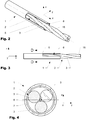
- Figure 1 shows a variation of a charging cable 10 according to the disclosure.
- Figure 2 shows a first variation of a liquid cooled cable 1 according to the disclosure in a perspective view.
- Figure 3 shows the liquid cooled cable 1 according to Figure 2 in a side view and
- Figure 4 shows a section view of the liquid cooled cable 1 according to section line DD of Figure 3 .
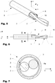
- Figure 5 shows a second variation of a liquid cooled cable 1 according to the disclosure in a perspective view.
- Figure 6 shows the liquid cooled cable 1 according to Figure 5 in a side view and Figure 7 shows a section view of the liquid cooled cable 1 according to section line DD of Figure 6 .
- a charging cable 10 usually comprises a first and a second liquid cooled cable 1 which usually have a similar design.
- the liquid cooled cables 1 are foreseen to transport electric current to an electric vehicle (not shown in detail) to charge the electric vehicle.
- the first and the second liquid cooled cable 1 are arranged in an outer hose 11 which help to protect the first and the second liquid cable against outer influences during operation.
- a flow hose 12 may be arranged in the outer hose 11 to return cooling liquid 15 flowing in the liquid cooled cables 1 as described hereinafter in more detail.
- two liquid cooled cables 1 can share a common flow hose 12.
- each liquid cooled cable 1 may comprise its own flow hose 12.
- the charging cable 10 may comprise a ground wire 13 and/or at least one data line 14 to transmit information along the charging cable 10.
- a liquid cooled cable 1 usually comprises a conductor 2 which comprises at least two cable strands 3.
- the cable strands 3 of the conductor 2 are encompassed by a hose 5.
- they are usually spaced at least partially apart from the hose 5 by an interstitial space 6 arranged between an inner wall 7 of the hose 5 and the cable strands 3 of the conductor 2.
- the interstitial space 6 is foreseen to conduct a cooling liquid 15 along the conductor 2. Good results can be achieved when the cooling liquid 15 is in direct contact with the outer wires 4 of the cable strands 3.
- the at least two cable strands 3 are stranded with respect to each other in a helical manner in a longitudinal direction x of the conductor 2.
- the interstitial space 6 which is defined by the strands 3 of the conductor 2 and the inner wall 7 of the hose 5, are also helically shaped forcing the cooling liquid 15 on a helical path around a center 16 of the conductor 2.
- the inner wall 7 of the hose 5 is flat thereby supporting a linear flow of the cooling liquid 15.
- the cable strands 3 each consist of a bundle of wires 4 stranded with respect to each other.
- the wires 4 of a strand 3 may be mechanically compressed with respect to each other.
- the conductor 2 comprises two cable strands 3 in a cross-section being spaced by 180° apart from each other with respect to a center 16 of the conductor 2 or three cable strands 3 in a cross-section being spaced by 120° apart from each other with respect to the center 16 of the conductor 2.
- the at least two cable strands 3 may be spaced apart from each other by a spacer (not shown in detail) arranged in a longitudinal direction between them.
- the hose 5 comprises an essentially circular cross-section offering an even distribution of the cooling liquid 15.
- the hose 5 is preferably self-supporting. Alternatively, it can e.g. be encompassed by a supporting structure, e.g. in the form of a spiral coil made from spring steel, maintaining the cross-section when lateral forces occur or during bending. Good results can be achieved, when the conductor 2 is arranged laterally movable with respect to the hose 5 resulting in a variable interstitial space 6.
- the length of twist of the cable strands 3 is preferably in the range of 7 to 1 5 times the diameter of an envelope curve 9 of the corresponding conductor 2.
- the diameter of the inner wall 7 of the hose 5 is preferably in the range of 5% to 15% bigger than the diameter of an envelope curve 9 of the corresponding conductor 2. In both cases, depending on the field of application, other values may be possible.
- the charging cable 10 comprises two liquid cooled cables 1 arranged adjacent to each other.
- the charging cable 10 may comprise a flow hose 12 for the cooling liquid 15.
- the charging cable 10 comprises an outer hose 11.
Abstract
Description
- The present disclosure relates to a liquid cooled cable and a charging cable assembly comprising such a liquid cooled cable for charging of electric vehicles.
-
WO20064040A1 was first published in March 2020 -
CN106448852A was first published in February 2017 on behalf of Yangzhou Fengming Cable Co. Ltd. The disclosure is directed to a mining cable. The mining cable comprises three stranded cable cores, a water blocking tape, an armor layer and a sheath layer. The three stranded cable cores are uniformly distributed along the periphery of a strengthening core. A stranded strengthening part is arranged in a gap between adjacent stranded cable cores. -
WO17133893A1 was first published in August 2017 -
US6100467A was first published in August 2000 on behalf of Northern Cable and Automation LLC. The disclosure is directed to a water cooled electrical cable that includes a plurality of electrical conductors. A first terminal half includes a first wire pocket hole and a fluid port disposed in fluid communication with the first wire pocket hole. A first crimp tube disposed within and extending from the first wire pocket hole is crimped around one-half of the electrical conductors associated with a first polarity. A second terminal half includes a second wire pocket hole and a fluid port disposed in fluid communication with the second wire pocket hole. The second terminal half is connected with the first terminal half. A second crimp tube disposed within and extending from the second wire pocket hole is crimped around a remaining one-half of the plurality of electrical conductors associated with a second polarity. -
US3772454A was first published in November 1973 on behalf of USX A Corp. of DE Corp. The disclosure is directed to a torque balanced conductor cable which includes between three and six strands spiraled together with the torque exerted by the cable being approximately equal to the torque exerted by the strands. Each strand includes an insulated conductor as a core with steel wires stranded there around and the insulation extending into the interstices of the strands. Another species includes insulated conductors positioned in the outer valleys of the cable and a sheath extruded over the entire assembly. This second species may be used with the first species or with cables in which the strands have a steel wire core member. - To reduce charging time, charging cables and connectors (charging cable assemblies) for electric vehicles are usually required to transmit as much electrical power per time as possible to recharge a vehicle battery in a short period of time. To fulfill this requirement, at a given voltage, this requires high currents which tend to heat the conductors in which they are transmitted. At same time, the overall cable diameter should be as small as possible to reduce cable weight and increase flexibility for better handling and operation. However, the smaller the area (diameter) of the current carrying cross section of a conductor in the charging cable is, the higher the temperature raises during operation as more current has to be transmitted by the available area. One way to address this problem is to actively cool the conductors. One successful solution is presented in the above mentioned
WO17133893A1 - To realize comparably small copper cross sections, the conductors must be effectively cooled with a cooling liquid which is circulating in a cooling circuit. One object of the present disclosure is to provide an optimized charging cable which is less expensive in production and which offers, compared to the prior art, better charging performance. Parameters which are in favor of the performance of the charging cable are large copper cross section (area), large coolant passage cross-section (area), large inner circle radius, smooth surface of the coolant channel, less flow resistance, avoidance of selective heat accumulation.
- The liquid cooled cable according to the disclosure is preferably arranged in a charging cable for an electric vehicle to transport electric current to the electric vehicle to charge the electric vehicle. The charging cable usually comprises at the vehicle's end a connector by which it is interconnected to the vehicle during charging. The charging cable and the connector forming a charging cable assembly. The connector is preferably cooled itself to prevent negative local heating of the connector. In a preferred variation, a charging cable according to the present disclosure comprises a first and a second liquid cooled cable which usually have a similar design for balanced transportation of the current and prevent unwanted local heating. The first and the second liquid cooled cable are usually arranged in an outer hose which helps to protect the first and the second liquid cooled cable against outer influences during operation. Depending on the design of the charging cable, a flow hose may be arranged additionally in the outer hose. Thereby it becomes e.g. possible, to feed cooling liquid into the connector by which the charging cable is interconnected to the vehicle during charging to cool the connector. The cooling liquid is then returned in the liquid cooled cables, preferably from the vehicle to the charging station. Depending on the field of application, two liquid cooled cables can share a common flow hose. Alternatively or in addition, each liquid cooled cable may comprise its own flow hose. This may become appropriate, if each conductor must be controlled individually. Furthermore, the charging cable may comprise a ground wire and/or at least one or several data lines to transmit information along the charging cable.
- A liquid cooled cable according to the disclosure usually comprises a conductor which comprises at least two cable strands. Good results can be achieved, when the cable strands of the conductor are encompassed by a stable, self-supporting hose, which in a cross-sectional view is spaced at least partially apart from the cable-strands by an interstitial space arranged between an inner wall of the hose and the cable strands of the conductor. Depending on the shape of the cable in space, the interstitial space along the cable may be variable with respect to the conductor. The cable strands of the conductor can be arranged laterally displaceable in the hose, such that on one side they are position-dependent in contact with the inner wall of the hose, while on the opposite side they are spaced apart from the inner wall of the hose. The inner diameter of the hose is preferably larger than the outer diameter of the conductor as will be explained in more detail hereinafter.
- The interstitial space is foreseen to conduct a cooling liquid, e.g. in the form of an oil or another appropriate cooling fluid, along the conductor. Good results are achieved when the cooling liquid is in direct contact with the outer wires of the cable strands. However, if appropriate, the cable strands can be covered by a sheet, as long as cooling is not hindered in a negative manner. For obtaining reliable and robust results, the at least two cable strands are stranded with respect to each other in a helical manner in a longitudinal direction of the conductor. As a result, the interstitial space which is defined by the strands of the conductor and the inner wall of the hose, are also helically shaped forcing the cooling liquid on a helical path around a center of the conductor. Preferably the inner wall of the hose is smooth, thereby not negatively increasing resistance and supporting a linear flow of the cooling liquid along the conductor. Usually each cable strand consists of a bundle of wires stranded with respect to each other. To obtain a higher current carrying cross-section, the wires of a strand may be mechanically compressed with respect to each other. Good results can be e.g. achieved by rotary swaging and/or drawing the bundle of wires through an appropriate die compacting the wires accordingly. At a minimum, the conductor may comprise two cable strands in a cross-section being spaced by 180° apart from each other with respect to a center of the conductor. Preferably the conductor comprises three cable strands in a cross-section being spaced by 120° apart from each other with respect to the center of the conductor. If appropriate, the at least two cable strands may be spaced apart from each other by a spacer arranged in a longitudinal direction between them. As the spacer positions the cable strands further apart from each other, it would be possible to increase the surface of the conductor which is in contact with the cooling liquid, although the spacer may have a negative impact on the current carrying cross-section. If appropriate, the spacer can be made from conductive material itself.
- The hose preferably comprises an essentially circular cross-section offering an even distribution of the cooling liquid around the cable strands of the conductor. Depending on the field of application, other shapes of cross-sections may be appropriate. To avoide unwanted deformation of the interstitial space, the hose is usually self-supporting. Alternatively, or in addition, it can be encompassed by a supporting structure, e.g. in the form of a spiral coil e.g. made from spring steel, maintaining the cross-section when lateral forces occur or during bending. As mentioned above, good results can be achieved, when the conductor is at least to a certain extend arranged laterally movable with respect to the hose resulting in a variable interstitial space. The length of twist of the cable strands is preferably in the range of 7 to 1 5 times the diameter of an envelope curve of the corresponding conductor. Furthermore, the diameter of the inner wall of the hose is preferably in the range of 5% to 15% bigger than the diameter of an envelope curve of the corresponding conductor. In both cases, depending on the field of application, other values may be possible. In a preferred variation, the charging cable comprises two liquid cooled cables arranged essentially adjacent to each other. In addition, the charging cable may comprise a flow hose for the cooling liquid. For better protection, the charging cable usually comprises an outer hose.
- Method for making of a liquid cooled cable usually comprises the following method steps: Providing a conductor comprising at least two cable strands. Encompassing the conductor by a hose preferably extruded over the at least two cable strands in a continuous manner spaced in a sectional view at least partially apart from the conductor by an interstitial space. Such that the interstitial space is arranged between an inner wall of the hose and the cable strands of the conductor. The at least two cable strands are during production preferably stranded with respect to each other in a helical manner in a longitudinal direction of the conductor before the hose is applied. If appropriate, the wires of at least one cable strand can be mechanically compressed with respect to each other before the hose is extruded over the at least two cable strands. Good results can be achieved e.g. by rotary swaging and/or a die. The hose is preferably extruded over the cable strands in a continuous manner, e.g. by a respective nozzle arranged coaxially with respect to the conductor of at least two cable strands.
- It is to be understood that both the foregoing general description and the following detailed description present embodiments, and are intended to provide an overview or framework for understanding the nature and character of the disclosure. The accompanying drawings are included to provide a further understanding, and are incorporated into and constitute a part of this specification. The drawings illustrate various embodiments, and together with the description serve to explain the principles and operation of the concepts disclosed.
- The herein described disclosure will be more fully understood from the detailed description given herein below and the accompanying drawings which should not be considered limiting to the disclosure described in the appended claims. The drawings are showing:
- Fig. 1
- a variation of a cross-section of a charging cable according to the disclosure;
- Fig. 2
- a perspective view of a first variation of a liquid cooled cable according to the disclosure;
- Fig. 3
- a side view of the liquid cooled cable according to
Figure 2 ; - Fig. 4
- a section view along section line DD according to
Figure 3 ; - Fig. 5
- a perspective view of a second variation of a liquid cooled cable according to the disclosure;
- Fig. 6
- a side view of the liquid cooled cable according to
Figure 5 ; - Fig. 7
- a section view along section line DD according to
Figure 6 . - Reference will now be made in detail to certain embodiments, examples of which are illustrated in the accompanying drawings, in which some, but not all features are shown. Indeed, embodiments disclosed herein may be embodied in many different forms and should not be construed as limited to the embodiments set forth herein; rather, these embodiments are provided so that this disclosure will satisfy applicable legal requirements. Whenever possible, like reference numbers will be used to refer to like components or parts.
-
Figure 1 shows a variation of a chargingcable 10 according to the disclosure.Figure 2 shows a first variation of a liquid cooledcable 1 according to the disclosure in a perspective view.Figure 3 shows the liquid cooledcable 1 according toFigure 2 in a side view andFigure 4 shows a section view of the liquid cooledcable 1 according to section line DD ofFigure 3 .Figure 5 shows a second variation of a liquid cooledcable 1 according to the disclosure in a perspective view.Figure 6 shows the liquid cooledcable 1 according toFigure 5 in a side view andFigure 7 shows a section view of the liquid cooledcable 1 according to section line DD ofFigure 6 . - In a variation, a charging
cable 10 according to the present disclosure usually comprises a first and a second liquid cooledcable 1 which usually have a similar design. The liquid cooledcables 1 are foreseen to transport electric current to an electric vehicle (not shown in detail) to charge the electric vehicle. The first and the second liquid cooledcable 1 are arranged in anouter hose 11 which help to protect the first and the second liquid cable against outer influences during operation. As shown in inFigure 1 , aflow hose 12 may be arranged in theouter hose 11 to return coolingliquid 15 flowing in the liquid cooledcables 1 as described hereinafter in more detail. Depending on the field of application, two liquid cooledcables 1 can share acommon flow hose 12. Alternatively or in addition, each liquid cooledcable 1 may comprise itsown flow hose 12. If necessary, the chargingcable 10 may comprise aground wire 13 and/or at least onedata line 14 to transmit information along the chargingcable 10. - A liquid cooled
cable 1 according to the present disclosure usually comprises aconductor 2 which comprises at least twocable strands 3. Thecable strands 3 of theconductor 2 are encompassed by ahose 5. In a cross-sectional view, they are usually spaced at least partially apart from thehose 5 by aninterstitial space 6 arranged between aninner wall 7 of thehose 5 and thecable strands 3 of theconductor 2. Theinterstitial space 6 is foreseen to conduct a coolingliquid 15 along theconductor 2. Good results can be achieved when the coolingliquid 15 is in direct contact with theouter wires 4 of thecable strands 3. Usually, the at least twocable strands 3 are stranded with respect to each other in a helical manner in a longitudinal direction x of theconductor 2. As a result, theinterstitial space 6 which is defined by thestrands 3 of theconductor 2 and theinner wall 7 of thehose 5, are also helically shaped forcing the coolingliquid 15 on a helical path around acenter 16 of theconductor 2. Preferably theinner wall 7 of thehose 5 is flat thereby supporting a linear flow of the coolingliquid 15. Preferably, thecable strands 3 each consist of a bundle ofwires 4 stranded with respect to each other. To obtain a higher area current carrying cross-section, thewires 4 of astrand 3 may be mechanically compressed with respect to each other. Preferably, theconductor 2 comprises twocable strands 3 in a cross-section being spaced by 180° apart from each other with respect to acenter 16 of theconductor 2 or threecable strands 3 in a cross-section being spaced by 120° apart from each other with respect to thecenter 16 of theconductor 2. If appropriate, the at least twocable strands 3 may be spaced apart from each other by a spacer (not shown in detail) arranged in a longitudinal direction between them. Thereby it would be possible to obtain a more even internal cooling. Preferably, thehose 5 comprises an essentially circular cross-section offering an even distribution of the coolingliquid 15. Depending on the field of application, other shapes of cross-sections may be appropriate. Thehose 5 is preferably self-supporting. Alternatively, it can e.g. be encompassed by a supporting structure, e.g. in the form of a spiral coil made from spring steel, maintaining the cross-section when lateral forces occur or during bending. Good results can be achieved, when theconductor 2 is arranged laterally movable with respect to thehose 5 resulting in a variableinterstitial space 6. The length of twist of thecable strands 3 is preferably in the range of 7 to 1 5 times the diameter of anenvelope curve 9 of the correspondingconductor 2. Furthermore, the diameter of theinner wall 7 of thehose 5 is preferably in the range of 5% to 15% bigger than the diameter of anenvelope curve 9 of the correspondingconductor 2. In both cases, depending on the field of application, other values may be possible. In a preferred variation, the chargingcable 10 comprises two liquid cooledcables 1 arranged adjacent to each other. In addition, the chargingcable 10 may comprise aflow hose 12 for the coolingliquid 15. For better protection, the chargingcable 10 comprises anouter hose 11. - The words used in the specification are words of description rather than limitation, and it is understood that various changes may be made without departing from the spirit and the scope of the disclosure
-
- 1
- Liquid cooled cable
- 2
- Conductor
- 3
- Cable strand
- 4
- Wire (cable wire)
- 5
- Hose (conductor hose)
- 6
- Interstitial space
- 7
- Inner wall (hose)
- 9
- Envelope curve (conductor)
- 10
- Charging cable
- 11
- Outer hose
- 12
- Flow hose (cooling liquid)
- 13
- Ground wire / Ground cable
- 14
- Data line
- 15
- Cooling liquid
- 16
- Center (of conductor)
Claims (18)
- Liquid cooled cable (1) comprisinga. a conductor (2) comprising at least two cable strands (3);b. the conductor (2) being encompassed by a hose (5) spaced in a sectional view at least partially apart from the conductor (2) by an interstitial space (6) arranged between an inner wall (7) of the hose (4) and the cable strands (3) of the conductor (2);c. said interstitial space (6) being foreseen to conduct a cooling liquid (15) in the hose (5) along the conductor (2).
- The liquid cooled cable (1) according to claim 1, wherein the at least two cable strands (3) are stranded with respect to each other in a helical manner in a longitudinal direction (x) of the conductor (2).
- The liquid cooled cable (1) according to at least one of the preceding claims, wherein the at least two cable strands (3) consist of wires (4) stranded with respect to each other.
- The liquid cooled cable (1) according to claim 3, wherein the wires (4) of a cable strand (3) are mechanically compressed with respect to each other.
- The liquid cooled cable (1) according to at least one of the preceding claims, wherein the conductor (2) comprisesa. two cable strands (3) in a cross-section being spaced by 180° apart from each other with respect to a center (16) of the conductor (2); orb. three cable strands (3) in a cross-section being spaced by 120° apart from each other with respect to the center (16) of the conductor (2).
- The liquid cooled cable (1) according to at least one of the preceding claims, wherein the at least two cable strands (3) are spaced apart from each other by a spacer.
- The liquid cooled cable (1) according to at least one of the preceding claims, wherein the hose (5) comprises an essentially circular cross-section.
- The liquid cooled cable (1) according to at least one of the preceding claims, wherein the hose (5) is self-supporting.
- The liquid cooled cable (1) according to at least one of the preceding claims, wherein the conductor (2) is arranged laterally movable with respect to the hose (5) resulting in a variable interstitial space (6).
- The liquid cooled cable (1) according to at least one of the preceding claims, wherein the length of twist of the cable strands (3) is in the range of 7 to 15 times the diameter of an envelope curve (9) of the corresponding conductor (2).
- The liquid cooled cable (1) according to at least one of the preceding claims, wherein the diameter of the inner wall (7) of the hose (5) is in the range of 5% to 15% bigger than the diameter of an envelope curve (9) of the corresponding conductor (2).
- Charging cable (10) comprising at least one liquid cooled cable (1) according to at least one of the preceding claims.
- Charging cable (10) according to claim 12, wherein the charging cable (10) comprises two liquid cooled cables (1) arranged adjacent to each other.
- Charging cable (10) according to claim 12 or claim 13, wherein the charging cable (10) comprises a flow hose (12) for the cooling liquid (15).
- Charging cable (10) according to at least one of the claims 12 through 14, wherein the charging cable (10) comprises an outer hose (11).
- Method for making of a liquid cooled cable (1) comprising the following method steps:a. providing a conductor (2) comprising at least two cable strands (3);b. encompassing the conductor (2) by a hose (5) extruded over the at least two cable strands (3) in a continuous manner spaced in a sectional view at least partially apart from the conductor (2) by an interstitial space (6) arranged between an inner wall (7) of the hose (5) and the cable strands (3) of the conductor (2);c. said interstitial space (6) being foreseen to conduct a cooling liquid (15) in the hose (5) along the conductor (2).
- Method according to claim 16, wherein the at least two cable strands (3) during production are stranded with respect to each other in a helical manner in a longitudinal direction (x) of the conductor (2).
- Method according to claim 16 or 17, wherein the wires (4) of at least one cable strand (3) are mechanically compressed the with respect to each other before the hose (5) is extruded over the at least two cable strands ().
Applications Claiming Priority (1)
| Application Number | Priority Date | Filing Date | Title |
|---|---|---|---|
| DE102020003868 | 2020-06-26 |
Publications (1)
| Publication Number | Publication Date |
|---|---|
| EP3929945A1 true EP3929945A1 (en) | 2021-12-29 |
Family
ID=75936690
Family Applications (1)
| Application Number | Title | Priority Date | Filing Date |
|---|---|---|---|
| EP21173724.2A Pending EP3929945A1 (en) | 2020-06-26 | 2021-05-13 | Liquid cooled cable and charging cable assembly |
Country Status (3)
| Country | Link |
|---|---|
| US (1) | US11476015B2 (en) |
| EP (1) | EP3929945A1 (en) |
| CN (1) | CN113851269A (en) |
Cited By (1)
| Publication number | Priority date | Publication date | Assignee | Title |
|---|---|---|---|---|
| WO2024032773A1 (en) * | 2022-08-12 | 2024-02-15 | 长春捷翼汽车科技股份有限公司 | Liquid-cooled cable |
Citations (14)
| Publication number | Priority date | Publication date | Assignee | Title |
|---|---|---|---|---|
| US2175749A (en) | 1937-02-23 | 1939-10-10 | American Coach And Body Compan | Cable construction |
| DE815207C (en) | 1948-12-24 | 1951-10-01 | Siemens & Halske A G | Electrical cable with several, in particular with two, three or four cores stranded around a common axis |
| US3603715A (en) * | 1968-12-07 | 1971-09-07 | Kabel Metallwerke Ghh | Arrangement for supporting one or several superconductors in the interior of a cryogenic cable |
| US3772454A (en) | 1972-11-22 | 1973-11-13 | Steel Corp | Torque balanced cable |
| US4647712A (en) * | 1984-02-10 | 1987-03-03 | Les Cables De Lyon | Electric cable for transportation very high current at low voltage, and methods of manufacturing such a cable |
| US6100467A (en) | 1998-02-19 | 2000-08-08 | Flex-Cable, Inc. | Water cooled kickless electrical cable |
| US6506976B1 (en) | 1999-09-14 | 2003-01-14 | Avaya Technology Corp. | Electrical cable apparatus and method for making |
| EP2682954A2 (en) | 2012-07-03 | 2014-01-08 | Nexans | Twisted pair spacer tape for use in lan cable |
| WO2014007643A1 (en) | 2012-07-04 | 2014-01-09 | Aker Subsea As | Heat dissipation in a power cable or a power umbilical |
| CN106448852A (en) | 2016-11-25 | 2017-02-22 | 扬州市凤鸣电缆有限公司 | Safe and reliable special mining cable |
| DE102015120048A1 (en) | 2015-11-19 | 2017-05-24 | Dr. Ing. H.C. F. Porsche Aktiengesellschaft | Electrical line arrangement |
| WO2017133893A1 (en) | 2016-02-01 | 2017-08-10 | Huber+Suhner Ag | Cable assembly |
| US20190237218A1 (en) * | 2018-02-01 | 2019-08-01 | Dr. Ing. H.C. F. Porsche Aktiengesellschaft | Motor vehicle charging cable |
| WO2020064040A1 (en) | 2018-09-25 | 2020-04-02 | Leoni Kabel Gmbh | Electric stranded wire |
Family Cites Families (8)
| Publication number | Priority date | Publication date | Assignee | Title |
|---|---|---|---|---|
| SE429276B (en) * | 1978-12-21 | 1983-08-22 | Volvo Ab | WATER-COOLED COAXIAL CABLE |
| US6472614B1 (en) * | 2000-01-07 | 2002-10-29 | Coflexip | Dynamic umbilicals with internal steel rods |
| TWM340532U (en) * | 2008-01-15 | 2008-09-11 | Zheng-Xiong Wu | Energy-saving electric wire and cable |
| DE102016206266A1 (en) * | 2016-04-14 | 2017-10-19 | Phoenix Contact E-Mobility Gmbh | Charging cable for transmitting electrical energy, charging plug and charging station for delivering electrical energy to a receiver of electrical energy |
| EP3459087B1 (en) * | 2016-05-20 | 2020-12-23 | Southwire Company, LLC | Liquid cooled charging cable system |
| JP6078198B1 (en) * | 2016-07-29 | 2017-02-08 | 株式会社フジクラ | Power supply cable and power supply cable with connector |
| DE102016118193A1 (en) * | 2016-09-27 | 2018-03-29 | Phoenix Contact E-Mobility Gmbh | Electrical cable with a coolant line |
| DE102016224106A1 (en) * | 2016-12-05 | 2018-06-07 | Leoni Kabel Gmbh | High current cable and power supply system with high current cable |
-
2021
- 2021-05-13 EP EP21173724.2A patent/EP3929945A1/en active Pending
- 2021-05-14 CN CN202110526528.2A patent/CN113851269A/en active Pending
- 2021-05-20 US US17/325,917 patent/US11476015B2/en active Active
Patent Citations (14)
| Publication number | Priority date | Publication date | Assignee | Title |
|---|---|---|---|---|
| US2175749A (en) | 1937-02-23 | 1939-10-10 | American Coach And Body Compan | Cable construction |
| DE815207C (en) | 1948-12-24 | 1951-10-01 | Siemens & Halske A G | Electrical cable with several, in particular with two, three or four cores stranded around a common axis |
| US3603715A (en) * | 1968-12-07 | 1971-09-07 | Kabel Metallwerke Ghh | Arrangement for supporting one or several superconductors in the interior of a cryogenic cable |
| US3772454A (en) | 1972-11-22 | 1973-11-13 | Steel Corp | Torque balanced cable |
| US4647712A (en) * | 1984-02-10 | 1987-03-03 | Les Cables De Lyon | Electric cable for transportation very high current at low voltage, and methods of manufacturing such a cable |
| US6100467A (en) | 1998-02-19 | 2000-08-08 | Flex-Cable, Inc. | Water cooled kickless electrical cable |
| US6506976B1 (en) | 1999-09-14 | 2003-01-14 | Avaya Technology Corp. | Electrical cable apparatus and method for making |
| EP2682954A2 (en) | 2012-07-03 | 2014-01-08 | Nexans | Twisted pair spacer tape for use in lan cable |
| WO2014007643A1 (en) | 2012-07-04 | 2014-01-09 | Aker Subsea As | Heat dissipation in a power cable or a power umbilical |
| DE102015120048A1 (en) | 2015-11-19 | 2017-05-24 | Dr. Ing. H.C. F. Porsche Aktiengesellschaft | Electrical line arrangement |
| WO2017133893A1 (en) | 2016-02-01 | 2017-08-10 | Huber+Suhner Ag | Cable assembly |
| CN106448852A (en) | 2016-11-25 | 2017-02-22 | 扬州市凤鸣电缆有限公司 | Safe and reliable special mining cable |
| US20190237218A1 (en) * | 2018-02-01 | 2019-08-01 | Dr. Ing. H.C. F. Porsche Aktiengesellschaft | Motor vehicle charging cable |
| WO2020064040A1 (en) | 2018-09-25 | 2020-04-02 | Leoni Kabel Gmbh | Electric stranded wire |
Cited By (1)
| Publication number | Priority date | Publication date | Assignee | Title |
|---|---|---|---|---|
| WO2024032773A1 (en) * | 2022-08-12 | 2024-02-15 | 长春捷翼汽车科技股份有限公司 | Liquid-cooled cable |
Also Published As
| Publication number | Publication date |
|---|---|
| US20210407706A1 (en) | 2021-12-30 |
| CN113851269A (en) | 2021-12-28 |
| US11476015B2 (en) | 2022-10-18 |
Similar Documents
| Publication | Publication Date | Title |
|---|---|---|
| JP5865481B2 (en) | Shield star quad cable | |
| EP3304567B1 (en) | Optical cable with electromagnetic field shield layer | |
| CN104350552B (en) | flexible power cable | |
| EP3734618B1 (en) | Charging system for an electric energy storage | |
| US20030132022A1 (en) | Communications cable and method for making same | |
| WO2017207266A1 (en) | Charging cable for transmitting electric energy, charging plug and charging station for discharging electric energy to a recipient of electric energy | |
| JP2012119073A (en) | Stranded conductor for insulated wire | |
| EP3929945A1 (en) | Liquid cooled cable and charging cable assembly | |
| KR101446192B1 (en) | Electrical control cable | |
| US10553334B2 (en) | Flat cable | |
| JP6506593B2 (en) | Cab-tire cable and cable with connector | |
| KR20220093165A (en) | Capacitive Power Transmission Cable | |
| US4853516A (en) | Electric cable primarily for welding equipment and welding device including the same | |
| EP3244423A1 (en) | Three core power cables with plastic armor | |
| CN210984369U (en) | Liquid cooling cable structure | |
| EP2899075B1 (en) | Vehicle battery cable | |
| JP2012198996A (en) | Flat cable, and wiring harness | |
| US20080296043A1 (en) | Electric control cable | |
| EP3244422B1 (en) | Three core power cables with surrounding plastic filler | |
| CN111599522B (en) | Anti-distortion cable | |
| US20160042840A1 (en) | High-speed data cable | |
| CN110379543B (en) | Conductor, wire and cable | |
| CA1304795C (en) | Electrical cable primarily for welding equipment | |
| CN203102986U (en) | Silicone rubber insulation power flexible cable with rated voltage of 6 to 15kV | |
| EP0186992B1 (en) | Optical cables |
Legal Events
| Date | Code | Title | Description |
|---|---|---|---|
| PUAI | Public reference made under article 153(3) epc to a published international application that has entered the european phase |
Free format text: ORIGINAL CODE: 0009012 |
|
| STAA | Information on the status of an ep patent application or granted ep patent |
Free format text: STATUS: THE APPLICATION HAS BEEN PUBLISHED |
|
| AK | Designated contracting states |
Kind code of ref document: A1 Designated state(s): AL AT BE BG CH CY CZ DE DK EE ES FI FR GB GR HR HU IE IS IT LI LT LU LV MC MK MT NL NO PL PT RO RS SE SI SK SM TR |
|
| B565 | Issuance of search results under rule 164(2) epc |
Effective date: 20211013 |
|
| RAP3 | Party data changed (applicant data changed or rights of an application transferred) |
Owner name: HUBER+SUHNER AG |
|
| STAA | Information on the status of an ep patent application or granted ep patent |
Free format text: STATUS: REQUEST FOR EXAMINATION WAS MADE |
|
| 17P | Request for examination filed |
Effective date: 20220628 |
|
| RBV | Designated contracting states (corrected) |
Designated state(s): AL AT BE BG CH CY CZ DE DK EE ES FI FR GB GR HR HU IE IS IT LI LT LU LV MC MK MT NL NO PL PT RO RS SE SI SK SM TR |
|
| STAA | Information on the status of an ep patent application or granted ep patent |
Free format text: STATUS: EXAMINATION IS IN PROGRESS |
|
| 17Q | First examination report despatched |
Effective date: 20230313 |
|
| TPAC | Observations filed by third parties |
Free format text: ORIGINAL CODE: EPIDOSNTIPA |