EP3458751B1 - Ventilpatrone für ein magnetventil und zugehöriges magnetventil - Google Patents
Ventilpatrone für ein magnetventil und zugehöriges magnetventil Download PDFInfo
- Publication number
- EP3458751B1 EP3458751B1 EP17713254.5A EP17713254A EP3458751B1 EP 3458751 B1 EP3458751 B1 EP 3458751B1 EP 17713254 A EP17713254 A EP 17713254A EP 3458751 B1 EP3458751 B1 EP 3458751B1
- Authority
- EP
- European Patent Office
- Prior art keywords
- valve
- armature
- plunger
- insert
- valve cartridge
- Prior art date
- Legal status (The legal status is an assumption and is not a legal conclusion. Google has not performed a legal analysis and makes no representation as to the accuracy of the status listed.)
- Active
Links
Images


Classifications
-
- F—MECHANICAL ENGINEERING; LIGHTING; HEATING; WEAPONS; BLASTING
- F16—ENGINEERING ELEMENTS AND UNITS; GENERAL MEASURES FOR PRODUCING AND MAINTAINING EFFECTIVE FUNCTIONING OF MACHINES OR INSTALLATIONS; THERMAL INSULATION IN GENERAL
- F16K—VALVES; TAPS; COCKS; ACTUATING-FLOATS; DEVICES FOR VENTING OR AERATING
- F16K31/00—Actuating devices; Operating means; Releasing devices
- F16K31/02—Actuating devices; Operating means; Releasing devices electric; magnetic
- F16K31/06—Actuating devices; Operating means; Releasing devices electric; magnetic using a magnet, e.g. diaphragm valves, cutting off by means of a liquid
- F16K31/0644—One-way valve
- F16K31/0655—Lift valves
-
- F—MECHANICAL ENGINEERING; LIGHTING; HEATING; WEAPONS; BLASTING
- F16—ENGINEERING ELEMENTS AND UNITS; GENERAL MEASURES FOR PRODUCING AND MAINTAINING EFFECTIVE FUNCTIONING OF MACHINES OR INSTALLATIONS; THERMAL INSULATION IN GENERAL
- F16K—VALVES; TAPS; COCKS; ACTUATING-FLOATS; DEVICES FOR VENTING OR AERATING
- F16K31/00—Actuating devices; Operating means; Releasing devices
- F16K31/02—Actuating devices; Operating means; Releasing devices electric; magnetic
- F16K31/06—Actuating devices; Operating means; Releasing devices electric; magnetic using a magnet, e.g. diaphragm valves, cutting off by means of a liquid
- F16K31/0686—Braking, pressure equilibration, shock absorbing
- F16K31/0693—Pressure equilibration of the armature
-
- B—PERFORMING OPERATIONS; TRANSPORTING
- B60—VEHICLES IN GENERAL
- B60T—VEHICLE BRAKE CONTROL SYSTEMS OR PARTS THEREOF; BRAKE CONTROL SYSTEMS OR PARTS THEREOF, IN GENERAL; ARRANGEMENT OF BRAKING ELEMENTS ON VEHICLES IN GENERAL; PORTABLE DEVICES FOR PREVENTING UNWANTED MOVEMENT OF VEHICLES; VEHICLE MODIFICATIONS TO FACILITATE COOLING OF BRAKES
- B60T8/00—Arrangements for adjusting wheel-braking force to meet varying vehicular or ground-surface conditions, e.g. limiting or varying distribution of braking force
- B60T8/32—Arrangements for adjusting wheel-braking force to meet varying vehicular or ground-surface conditions, e.g. limiting or varying distribution of braking force responsive to a speed condition, e.g. acceleration or deceleration
- B60T8/34—Arrangements for adjusting wheel-braking force to meet varying vehicular or ground-surface conditions, e.g. limiting or varying distribution of braking force responsive to a speed condition, e.g. acceleration or deceleration having a fluid pressure regulator responsive to a speed condition
- B60T8/36—Arrangements for adjusting wheel-braking force to meet varying vehicular or ground-surface conditions, e.g. limiting or varying distribution of braking force responsive to a speed condition, e.g. acceleration or deceleration having a fluid pressure regulator responsive to a speed condition including a pilot valve responding to an electromagnetic force
- B60T8/3615—Electromagnetic valves specially adapted for anti-lock brake and traction control systems
- B60T8/363—Electromagnetic valves specially adapted for anti-lock brake and traction control systems in hydraulic systems
Definitions
- the invention relates to a valve cartridge for a solenoid valve according to the preamble of independent claim 1.
- the present invention also relates to a solenoid valve with such a valve cartridge.
- a plunger with a closing element is used as the sealing element in normally open solenoid valves.
- the ram guide is usually designed as a cloverleaf profile with several bars and cutouts.
- the recesses between the webs are intended to ensure volume compensation between a sealing area of the valve and an armature space.
- the webs themselves are intended to limit the tilt angle between the valve insert and tappet. As long as the valve insert shows only small partial roundness deviations, which are smaller in the circumferential direction than the web width, this is also effective. If the area is larger, the ram can tip more locally at this point. However, the tilt angle has an influence on the pressure control accuracy and its scatter or reproducibility.
- a generic valve cartridge for a solenoid valve which comprises a capsule, an armature movably guided within the capsule, a hollow cylindrical valve insert which is inserted into the capsule with a first end, and a valve body with a main valve seat which is inserted into a second end of the hollow cylindrical valve insert is introduced.
- the armature moves a plunger guided inside the valve insert, which has a base body and a closing body with a closing element, which plunges sealingly into the main valve seat of the valve body to perform a sealing function.
- At least one compensating groove is provided in the base body of the tappet, which compensates for volume enables between a sealing area and an armature space, the plunger having an axial recess which has an overlap with the at least one compensating groove in the base body and is connected to the armature space via a radial recess arranged on an end of the plunger facing the armature.
- An electromagnetic valve is known with two valve closing bodies arranged in series in a valve housing, which can be actuated depending on the switching position of a magnet armature, the end face of which is provided with a through hole, so that the end face, which faces away from a magnetic core fixed in the valve housing, is designed as an annular surface , which can be placed on an end face of the first valve closing body, which contacts the second valve closing body under the action of a return spring.
- a cavity is provided between the ring surface and the end surface.
- the housing has a cylindrical guide element that is configured to support the axial movement of the armature.
- a seat member with a through opening formed therein is inserted into the guide element, at the end of which a valve seat is formed.
- a stationary pole core is arranged in a sleeve in such a way that it has a predetermined distance in the axial direction from an end section of the guide element. The sleeve is fluid-tightly connected to an outer circumference of an end section of the pole core and an outer circumference of the end section of the guide element.
- the armature moves a plunger, which has a closing body with a closing element, which plunges sealingly into the valve seat of the seat member to perform a sealing function.
- At least one equalization groove is made in the armature, which enables volume equalization between a sealing area and an armature space.
- a valve cartridge which has a sleeve, a valve insert connected to the sleeve, a valve armature which is axially movably guided within the sleeve against the force of a return spring between a closed position and an open position and which is coupled to a plunger with a closing geometry, and one to the Valve insert connected valve body with a valve seat, which is arranged between at least a first fluid opening and at least a second fluid opening.
- the closing geometry acts in a sealing manner with a seat geometry of the valve seat and interrupts a fluid flow between the at least one first fluid opening and the at least one second fluid opening.
- the closing geometry is raised from the valve seat and enables the fluid flow between the at least one first fluid opening and the at least one second fluid opening.
- valve cartridge for a solenoid valve with the features of independent claim 1 has the advantage that the tipping of the tappet can also be limited in the event of larger partial roundness deviations by the circumferential cylindrical outer contour on one end of the tappet facing the armature.
- embodiments of the valve cartridge according to the invention are more robust with respect to manufacturing tolerances. This applies in an advantageous manner to the pressure control accuracy, its dispersion due to component tolerances and the reproducibility with one and the same valve cartridge.
- the volume compensation between a sealing area and an armature space is further advantageously ensured by an axial recess which has an overlap with at least one compensating groove in the base body and is connected to the armature space via at least one radial recess.
- the cylindrical outer contour arranged at the end of the plunger radially restricts the range of motion over the entire circumference. This results in an advantageously improved, more precise guidance of the tappet in the valve insert.
- the narrowing of the cross section in the guide region of the cylindrical outer contour advantageously has no influence on the switching speed due to the volume compensation.
- the design of the ram can be produced using the existing machines or tool concepts. All that is required is a simple adjustment of the tool cavities and a protection in terms of the injection molding process.
- Embodiments of the present invention provide a valve cartridge for a solenoid valve, which has a capsule, an armature movably guided within the capsule, a hollow cylindrical valve insert, which is connected to a first end is inserted into the capsule, and comprises a valve body with a main valve seat, which is inserted into a second end of the hollow cylindrical valve insert.
- the armature moves a plunger guided inside the valve insert, which has a base body and a closing body with a closing element, which plunges sealingly into the main valve seat of the valve body to perform a sealing function.
- At least one equalization groove is made in the base body of the tappet, which enables volume equalization between a sealing area and an armature space.
- the tappet has at its end facing the armature a circumferential cylindrical outer contour, which forms a radial guidance of the tappet in the valve insert, and an axial recess, which has an overlap with the at least one compensating groove in the base body and via at least one radial recess with the Anchor room is connected.
- a solenoid valve with a magnet assembly and such a valve cartridge is proposed, an armature being movably guided within the valve cartridge, which armature can be moved by a magnetic force generated by the magnet assembly.
- the base body can have a plurality of webs and compensating grooves, each of which has an overlap with the axial recess.
- a plurality of radial recesses can be formed on an armature contact surface of the plunger, which can connect the axial recess to the armature space.
- the dimensions of the axial recess as well as the number and dimensions of the compensating grooves and the radial recesses can advantageously be chosen and implemented in such a way that the requirements for the damping behavior and the valve dynamics are met or maintained.
- the tappet can be designed as a plastic injection-molded part, on the base body of which Hollow cylinder with the cylindrical outer contour and the axial recess and the at least one radial recess can be injection molded. This enables a particularly simple and inexpensive manufacture of the tappet for the valve cartridge.
- the valve insert can be designed as an inexpensive, one-piece, slotted sleeve.
- the valve body can be designed, for example, as a hood-shaped sleeve, which can be pressed into the second end of the valve insert in such a way that the main valve seat is arranged inside the valve insert.
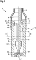
- the illustrated embodiment of a valve cartridge 1 according to the invention for a solenoid valve comprises a capsule 3, an armature 5 guided movably within the capsule 3, a hollow cylindrical valve insert 8, which is inserted into the capsule 3 with a first end, and a valve body 9 with a main valve seat 9.1, which is inserted into a second end of the hollow cylindrical valve insert 8.
- the armature 5 moves a plunger 10 which is guided within the valve insert 8 and which has a base body 11 and a closing body 11.1 with a closing element 11.2, which plunges sealingly into the main valve seat 9.1 of the valve body 9 in order to carry out a sealing function.
- At least one compensating groove 16 is made in the base body 11 of the tappet 10, which enables a volume compensation 14 between a sealing area 9.2 and an armature space 7.
- the plunger 10 has at its end facing the armature 5 a circumferential cylindrical outer contour 12, which forms a radial guide 19 of the plunger 10 in the valve insert 8, and an axial recess 13, which overlaps 17 with the at least one compensating groove 16 in the base body 11 and is connected to the armature space 7 via at least one radial recess 18.
- the base body 11 of the plunger 10 in the illustrated embodiment is designed as a cloverleaf profile with four webs 15 and compensating grooves 16, each of which has an overlap 17 with the axial recess 13.
- a different number of webs 16 and compensating grooves 16 can of course also be provided.
- the plunger 10 is designed as an inexpensive plastic injection-molded part, on the base body 11 of which a hollow cylinder with the cylindrical outer contour 12 and the axial recess 13 and the four radial recesses 18 is injection molded.
- the valve insert 8 is designed as a one-piece slotted sleeve.
- the valve body 9 is designed as a hood-shaped sleeve which is pressed into the second end of the valve insert 8 such that the main valve seat 9.1 is arranged inside the valve insert 8.
- the valve body 9 can be manufactured, for example, as a deep-drawn part.
- the recesses or compensation grooves 16 between the webs 15 are intended to ensure volume compensation 14 between the sealing area 9.1 and the armature space 7.
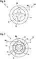
- the webs 15 themselves should be in a conventional, in Fig. 6 Limit valve cartridge 1H shown a tilt angle between valve insert 8 and plunger 10H.
- the valve insert 8 has only small partial roundness deviations RA, which are smaller in the circumferential direction than the web width, this is also effective. If the range of the roundness deviation RA is larger, then the effective radial play RS of the plunger 10H is larger and the plunger 10H of the conventional valve cartridge 1H can tip more locally at this point, as from Fig. 6 can be seen. How from Fig.
- valve cartridge 1 according to the invention is more robust with respect to manufacturing tolerances. This applies in particular to the pressure control accuracy, its scatter due to component tolerances and the reproducibility with one and the same valve cartridge 1.
- valve cartridge 1 can be used, for example, in a normally open solenoid valve with a magnet assembly.
- the valve cartridge 1 becomes movable guided armature 5 moved by a magnetic force generated by the magnetic assembly, not shown, to close the solenoid valve, ie to press the closing element 11.2 in the main valve seat 9.1.
- the plunger 10 is returned to the open position when the magnet assembly is switched off by a return spring (not shown in more detail).
Landscapes
- Engineering & Computer Science (AREA)
- General Engineering & Computer Science (AREA)
- Mechanical Engineering (AREA)
- Magnetically Actuated Valves (AREA)
Description
- Die Erfindung geht aus von einer Ventilpatrone für ein Magnetventil nach der Gattung des unabhängigen Patentanspruchs 1. Gegenstand der vorliegenden Erfindung ist auch ein Magnetventil mit einer solchen Ventilpatrone.
- In stromlosoffenen Magnetventilen kommt als Dichtelement ein Stößel mit einem Schließelement zum Einsatz. Die Stößelführung wird in der Regel als Kleeblattprofil mit mehreren Stegen und Aussparungen ausgeführt. Die Aussparungen zwischen den Stegen sollen den Volumenausgleich zwischen einem Dichtbereich des Ventils und einem Ankerraum gewährleisten. Die Stege selbst sollen den Kippwinkel zwischen Ventileinsatz und Stößel begrenzen. Solange der Ventileinsatz nur kleine partielle Rundheitsabweichungen ausweist, welche in Umfangsrichtung kleiner als die Stegbreite sind, ist dies auch wirksam. Ist der Bereich größer, kann der Stößel an dieser Stelle lokal stärker kippen. Der Kippwinkel hat jedoch einen Einfluss auf die Druckstellgenauigkeit und deren Streuung bzw. Reproduzierbarkeit.
- Aus der
DE 199 49 222 A1 ist eine gattungsgemäße Ventilpatrone für ein Magnetventil bekannt, welche eine Kapsel, einen innerhalb der Kapsel beweglich geführten Anker, einen hohlzylindrischen Ventileinsatz, welcher mit einem ersten Ende in die Kapsel eingeschoben ist, und einen Ventilkörper mit einem Hauptventilsitz umfasst, welcher in ein zweites Ende des hohlzylindrischen Ventileinsatzes eingeführt ist. Der Anker bewegt einen innerhalb des Ventileinsatzes geführten Stößel, welcher einen Grundkörper und einen Schließkörper mit einem Schließelement aufweist, welches zur Ausführung einer Dichtfunktion dichtend in den Hauptventilsitz des Ventilkörpers eintaucht. In den Grundkörper des Stößels ist mindestens eine Ausgleichsnut eingebracht, welche einen Volumenausgleich zwischen einem Dichtbereich und einem Ankerraum ermöglicht, wobei der Stößel eine axiale Aussparung aufweist, welche eine Überschneidung mit der mindestens einen Ausgleichsnut im Grundkörper aufweist und über eine an einem dem Anker zugewandten Ende des Stößels angeordnete radiale Aussparung mit dem Ankerraum verbunden ist. - Aus der
DE 10 2012 207 986 A1 ist ein Elektromagnetventil mit in einem Ventilgehäuse in Reihe angeordneten zwei Ventilschließkörpern bekannt, die abhängig von der Schaltstellung eines Magnetankers betätigbar sind, dessen Stirnfläche mit einer Durchgangsbohrung versehen ist, sodass die Stirnfläche, die von einem im Ventilgehäuse fixierten Magnetkern abgewandt ist, als Ringfläche ausgebildet ist, die an einer Stirnfläche des ersten Ventilschließkörpers anlegbar ist, der unter der Wirkung einer Rückstellfeder den zweiten Ventilschließkörper kontaktiert. Um ein unerwünschtes Anhaften des ersten Ventilschließkörpers an der hydraulisch benetzten Ringfläche des Magnetankers zu verhindern, ist zwischen der Ringfläche und der Stirnfläche ein Hohlraum vorgesehen. - Aus der
US 2015/0137014 A1 ist elektromagnetisches Ventil mit einer Magnetbaugruppe, einem Gehäuse, einem Anker und einer Rückstellfeder bekannt. Das Gehäuse weist ein zylindrisches Führungselement auf, das so konfiguriert ist, dass es die axiale Bewegung des Ankers unterstützt. In das Führungselement ist ein Sitzglied mit einer darin ausgebildeten Durchgangsöffnung eingeführt, an deren Ende ein Ventilsitz ausgebildet ist. Ein ortsfester Polkern ist so in einer Hülse angeordnet, dass er in axialer Richtung einen vorgegebenen Abstand zu einem Endabschnitt des Führungselements aufweist. Die Hülse ist flüssigkeitsdicht mit je einem Außenumfang eines Endabschnitts des Polkerns und einem äußeren Umfang des Endabschnitts des Führungselements verbunden. Der Anker bewegt einen Stößel, welcher einen Schließkörper mit einem Schließelement aufweist, welches zur Ausführung einer Dichtfunktion dichtend in den Ventilsitz des Sitzgliedes eintaucht. In den Anker ist mindestens eine Ausgleichsnut eingebracht, welche einen Volumenausgleich zwischen einem Dichtbereich und einem Ankerraum ermöglicht. - Aus der
DE 10 2009 026 853 A1 ist beispielsweise eine Ventilpatrone bekannt, welche eine Hülse, einen mit der Hülse verbundenen Ventileinsatz, einen innerhalb der Hülse gegen die Kraft einer Rückstellfeder zwischen einer Geschlossenposition und einer Offenposition axial beweglich geführten Ventilanker, welcher mit einem Stößel mit Schließgeometrie gekoppelt ist, und einen mit dem Ventileinsatz verbundenen Ventilkörper mit einem Ventilsitz umfasst, welcher zwischen mindestens einer ersten Fluidöffnung und mindestens einer zweiten Fluidöffnung angeordnet ist. Die Schließgeometrie wirkt in der Geschlossenstellung dichtend mit einer Sitzgeometrie des Ventilsitzes zusammen und unterbricht eine Fluidströmung zwischen der mindestens einen ersten Fluidöffnung und der mindestens einen zweiten Fluidöffnung. In der Offenstellung ist die Schließgeometrie vom Ventilsitz abgehoben und ermöglicht die Fluidströmung zwischen der mindestens einen ersten Fluidöffnung und der mindestens einen zweiten Fluidöffnung. - Die Ventilpatrone für ein Magnetventil mit den Merkmalen des unabhängigen Patentanspruchs 1 hat den Vorteil, dass durch die umlaufende zylindrische Außenkontur an einem dem Anker zugewandten Ende des Stößels das Kippen des Stößels auch bei größeren partiellen Rundheitsabweichungen begrenzt werden kann. Zudem sind Ausführungsformen der erfindungsgemäßen Ventilpatrone gegenüber Fertigungstoleranzen robuster. Dies gilt in vorteilhafter Weise für die Druckstellgenauigkeit, deren Streuung aufgrund von Bauteiltoleranzen sowie die Reproduzierbarkeit bei ein und derselben Ventilpatrone. Der Volumenausgleich zwischen einem Dichtbereich und einem Ankerraum ist durch eine axiale Aussparung, welche eine Überschneidung mit mindestens einer Ausgleichsnut im Grundkörper aufweist und über mindestens eine radiale Aussparung mit dem Ankerraum verbunden ist, in vorteilhafter Weise weiterhin gewährleistet.
- Die am Ende des Stößels angeordnete zylindrische Außenkontur schränkt über den gesamten Umfang radial den Bewegungsbereich ein. Hieraus folgt eine in vorteilhafter Weise verbesserte, genauere Führung des Stößels im Ventileinsatz. Die Einengung des Querschnittes im Führungsbereich der zylindrischen Außenkontur hat durch den Volumenausgleich in vorteilhafter Weise keinen Einfluss auf die Schaltgeschwindigkeit.
- Bei einer Ausführung als Kunststoffspritzgussteil kann das Design des Stößels mit den vorhandenen Maschinen bzw. Werkzeugkonzepten hergestellt werden. Es bedarf nur einer einfachen Anpassung der Werkzeugkavitäten und eine spritzprozesstechnische Absicherung.
- Ausführungsformen der vorliegenden Erfindung stellen eine Ventilpatrone für ein Magnetventil zur Verfügung, welche eine Kapsel, einen innerhalb der Kapsel beweglich geführten Anker, einen hohlzylindrischen Ventileinsatz, welcher mit einem ersten Ende in die Kapsel eingeschoben ist, und einen Ventilkörper mit einem Hauptventilsitz umfasst, welcher in ein zweites Ende des hohlzylindrischen Ventileinsatzes eingeführt ist. Der Anker bewegt einen innerhalb des Ventileinsatzes geführten Stößel, welcher einen Grundkörper und einen Schließkörper mit einem Schließelement aufweist, welches zur Ausführung einer Dichtfunktion dichtend in den Hauptventilsitz des Ventilkörpers eintaucht. In den Grundkörper des Stößels ist mindestens eine Ausgleichsnut eingebracht, welche einen Volumenausgleich zwischen einem Dichtbereich und einem Ankerraum ermöglicht. Hierbei weist der Stößel an seinem dem Anker zugewandten Ende eine umlaufende zylindrische Außenkontur, welche eine radiale Führung des Stößels im Ventileinsatz ausbildet, und eine axiale Aussparung auf, welche eine Überschneidung mit der mindestens einen Ausgleichsnut im Grundkörper aufweist und über mindestens eine radiale Aussparung mit dem Ankerraum verbunden ist.
- Zudem wird ein Magnetventil mit einer Magnetbaugruppe und einer solchen Ventilpatrone vorgeschlagen, wobei innerhalb der Ventilpatrone ein Anker beweglich geführt ist, welcher von einer von der Magnetbaugruppe erzeugten Magnetkraft bewegbar ist.
- Durch die in den abhängigen Ansprüchen aufgeführten Maßnahmen und Weiterbildungen sind vorteilhafte Verbesserungen der im unabhängigen Patentanspruch 1 angegebenen Ventilpatrone für ein Magnetventil möglich.
- Besonders vorteilhaft ist, dass der Grundkörper mehrere Stege und Ausgleichsnuten aufweisen kann, welche jeweils eine Überschneidung mit der axialen Aussparung aufweisen. Zudem können an einer Ankeranlagefläche des Stößels mehrere radiale Aussparungen ausgebildet werden, welche die axiale Aussparung mit dem Ankerraum verbinden können. Die Abmessungen der axialen Aussparung sowie die Anzahl und Abmessungen der Ausgleichsnuten und der radialen Aussparungen können in vorteilhafter Weise so gewählt und ausgeführt werden, dass die Anforderungen an das Dämpfungsverhalten und die Ventildynamik erfüllt bzw. eingehalten werden.
- In vorteilhafter Ausgestaltung der Ventilpatrone für ein Magnetventil kann der Stößel als Kunststoffspritzteil ausgeführt werden, an dessen Grundkörper ein Hohlzylinder mit der zylindrischen Außenkontur und der axialen Aussparung und der mindestens einen radialen Aussparung angespritzt werden kann. Dies ermöglicht eine besonders einfache und kostengünstige Herstellung des Stößels für die Ventilpatrone.
- In weiterer vorteilhafter Ausgestaltung der Ventilpatrone für ein Magnetventil kann der Ventileinsatz als kostengünstige einteilige geschlitzte Hülse ausgeführt werden. Der Ventilkörper kann beispielsweise als haubenförmige Hülse ausgeführt werden, welche so in das zweite Ende des Ventileinsatzes eingepresst werden kann, dass der Hauptventilsitz innerhalb des Ventileinsatzes angeordnet ist.
- Ein Ausführungsbeispiel der Erfindung ist in der Zeichnung dargestellt und wird in der nachfolgenden Beschreibung näher erläutert.
-
-
Fig. 1 zeigt eine schematische Schnittdarstellung eines Ausführungsbeispiels einer Ventilpatrone für ein Magnetventil. -
Fig. 2 zeigt eine schematische Schnittdarstellung des Ausführungsbeispiels der Ventilpatrone für ein Magnetventil ausFig. 1 entlang der Schnittlinie II - II. -
Fig. 3 zeigt eine schematische Schnittdarstellung des Ausführungsbeispiels der Ventilpatrone für ein Magnetventil ausFig. 1 entlang der Schnittlinie III - III. -
Fig. 4 zeigt eine schematische Draufsicht von oben auf ein Ausführungsbeispiel eines Stößels der Ventilpatrone für ein Magnetventil ausFig. 1 . -
Fig. 5 zeigt eine schematische Draufsicht von unten auf ein Ausführungsbeispiel eines Stößels der Ventilpatrone für ein Magnetventil ausFig. 1 . -
Fig. 6 zeigt eine schematische Schnittdarstellung im Bereich des Ankerraums einer herkömmlichen Ventilpatrone für ein Magnetventil, deren Ventileinsatz eine partielle Rundheitsabweichung aufweist. -
Fig. 7 zeigt eine schematische Schnittdarstellung im Bereich des Ankerraums der Ventilpatrone für ein Magnetventil ausFig. 1 , deren Ventileinsatz eine partielle Rundheitsabweichung aufweist. - Wie aus
Fig. 1 bis 5 ersichtlich ist, umfasst das dargestellte Ausführungsbeispiel einer erfindungsgemäßen Ventilpatrone 1 für ein Magnetventil eine Kapsel 3, einen innerhalb der Kapsel 3 beweglich geführten Anker 5, einen hohlzylindrischen Ventileinsatz 8, welcher mit einem ersten Ende in die Kapsel 3 eingeschoben ist, und einen Ventilkörper 9 mit einem Hauptventilsitz 9.1, welcher in ein zweites Ende des hohlzylindrischen Ventileinsatzes 8 eingeführt ist. Der Anker 5 bewegt einen innerhalb des Ventileinsatzes 8 geführten Stößel 10, welcher einen Grundkörper 11 und einen Schließkörper 11.1 mit einem Schließelement 11.2 aufweist, welches zur Ausführung einer Dichtfunktion dichtend in den Hauptventilsitz 9.1 des Ventilkörpers 9 eintaucht. In den Grundkörper 11 des Stößels 10 ist mindestens eine Ausgleichsnut 16 eingebracht, welche einen Volumenausgleich 14 zwischen einem Dichtbereich 9.2 und einem Ankerraum 7 ermöglicht. Hierbei weist der Stößel 10 an seinem dem Anker 5 zugewandten Ende eine umlaufende zylindrische Außenkontur 12, welche eine radiale Führung 19 des Stößels 10 im Ventileinsatz 8 ausbildet, und eine axiale Aussparung 13 auf, welche eine Überschneidung 17 mit der mindestens einen Ausgleichsnut 16 im Grundkörper 11 aufweist und über mindestens eine radiale Aussparung 18 mit dem Ankerraum 7 verbunden ist. - Wie aus
Fig. 1 bis 5 weiter ersichtlich ist, ist der Grundkörper 11 des Stößels 10 im dargestellten Ausführung als Kleeblattprofil mit vier Stegen 15 und Ausgleichsnuten 16 ausgeführt, welche jeweils eine Überschneidung 17 mit der axialen Aussparung 13 aufweisen. Selbstverständlich kann auch eine andere Anzahl von Stegen 16 und Ausgleichsnuten 16 vorgesehen werden. - Wie aus
Fig. 1 bis 5 weiter ersichtlich ist, sind an einer Ankeranlagefläche des Stößels 10 vier radiale Aussparungen 18 ausgebildet, welche die axiale Aussparung 13 mit dem Ankerraum 7 verbinden. - Im dargestellten Ausführungsbeispiel ist der Stößel 10 als kostengünstiges Kunststoffspritzteil ausgeführt, an dessen Grundkörper 11 ein Hohlzylinder mit der zylindrischen Außenkontur 12 und der axialen Aussparung 13 und den vier radialen Aussparungen 18 angespritzt ist. Der Ventileinsatz 8 ist als einteilige geschlitzte Hülse ausgeführt. Der Ventilkörper 9 ist als haubenförmige Hülse ausgeführt, welche so in das zweite Ende des Ventileinsatzes 8 eingepresst ist, dass der Hauptventilsitz 9.1 innerhalb des Ventileinsatzes 8 angeordnet ist. Der Ventilkörper 9 kann beispielsweise als Tiefziehteil hergestellte werden.
- Die Aussparungen bzw. Ausgleichsnuten 16 zwischen den Stegen 15 sollen den Volumenausgleich 14 zwischen dem Dichtbereich 9.1 und dem Ankerraum 7 gewährleisten. Die Stege 15 selbst sollen bei einer herkömmlichen, in
Fig. 6 dargestellten Ventilpatrone 1H einen Kippwinkel zwischen Ventileinsatz 8 und Stößel 10H begrenzen. Solange der Ventileinsatz 8 nur kleine partielle Rundheitsabweichungen RA aufweist, welche in Umfangsrichtung kleiner als die Stegbreite sind ist dies auch wirksam. Ist der Bereich der Rundheitsabweichung RA größer, dann ist das wirksame Radialspiel RS des Stößels 10H größer und der Stößel 10H der herkömmlichen Ventilpatrone 1H kann an dieser Stelle lokal stärker kippen, wie ausFig. 6 ersichtlich ist. Wie ausFig. 7 weiter ersichtlich ist, wird durch die angespritzte zylindrische Außenkontur 12 das wirksame Radialspiel RS des Stößels und damit das Kippen des Stößels 10 bei Ausführungsformen einer erfindungsgemäßen Ventilpatrone 1 auch bei größeren partiellen Rundheitsabweichungen RA begrenzt. Dadurch sind Ausführungsformen der erfindungsgemäßen Ventilpatrone 1 gegenüber Fertigungstoleranzen robuster. Dies gilt insbesondere für die Druckstellgenauigkeit, deren Streuung aufgrund von Bauteiltoleranzen sowie die Reproduzierbarkeit bei ein und derselben Ventilpatrone 1. - Durch die zylindrische axiale Aussparung 13 sowie die radialen Aussparungen 18 an der Ankeranlagefläche des Stößels 10, welche die axiale Aussparung 13 mit dem Ankerraum 7 verbinden, ist der erforderliche Volumenausgleich zwischen Dichtbereich 9.2 und Ankerraum 7 in vorteilhafter Weise möglich.
- Das dargestellte Ausführungsbeispiel der erfindungsgemäßen Ventilpatrone 1 kann beispielsweise in einem stromlosoffenen Magnetventil mit einer Magnetbaugruppe eingesetzt werden. Hierbei wird der innerhalb der Ventilpatrone 1 beweglich geführte Anker 5 von einer von der nicht näher dargestellten Magnetbaugruppe erzeugten Magnetkraft bewegt, um das Magnetventil zu schließen, d.h. das Schließelement 11.2 in den Hauptventilsitz 9.1 zu drücken. Die Rückstellung des Stößels 10 in die Offenstellung erfolgt bei Abschalten der Magnetbaugruppe durch eine nicht näher dargestellte Rückstellfeder.
Claims (7)
- Ventilpatrone (1) für ein Magnetventil, mit einer Kapsel (3), einem innerhalb der Kapsel (3) beweglich geführten Anker (5), einem hohlzylindrischen Ventileinsatz (8), welcher mit einem ersten Ende in die Kapsel (3) eingeschoben ist, und einem Ventilkörper (9) mit einem Hauptventilsitz (9.1), welcher in ein zweites Ende des hohlzylindrischen Ventileinsatzes (8) eingeführt ist, wobei der Anker (5) einen innerhalb des Ventileinsatzes (8) geführten Stößel (10) bewegt, welcher einen Grundkörper (11) und einen Schließkörper (11.1) mit einem Schließelement (11.2) aufweist, welches zur Ausführung einer Dichtfunktion dichtend in den Hauptventilsitz (9.1) des Ventilkörpers (9) eintaucht, wobei mindestens eine Ausgleichsnut (16) in den Grundkörper (11) des Stößels (10) eingebracht ist, welche einen Volumenausgleich (14) zwischen einem Dichtbereich (9.2) und einem Ankerraum (7) ermöglicht, wobei der Stößel (10) eine axiale Aussparung (13) aufweist, welche eine Überschneidung (17) mit der mindestens einen Ausgleichsnut (16) im Grundkörper (11) aufweist und über mindestens eine radiale Aussparung (18) mit dem Ankerraum (7) verbunden ist, dadurch gekennzeichnet, dass der Stößel (10) an seinem dem Anker (5) zugewandten Ende eine geschlossene umlaufende zylindrische Außenkontur (12) aufweist, welche eine radiale Führung (19) des Stößels (10) im Ventileinsatz (8) ausbildet.
- Ventilpatrone nach Anspruch 1, dadurch gekennzeichnet, dass der Grundkörper (11) mehrere Stege (15) und Ausgleichsnuten (16) aufweist, welche jeweils eine Überschneidung (17) mit der axialen Aussparung (13) aufweisen.
- Ventilpatrone nach Anspruch 1 oder 2, dadurch gekennzeichnet, dass an einer Ankeranlagefläche des Stößels (10) mehrere radiale Aussparungen (18) ausgebildet sind, welche die axiale Aussparung (13) mit dem Ankerraum (7) verbinden.
- Ventilpatrone nach einem der Ansprüche 1 bis 3, dadurch gekennzeichnet, dass der Stößel (10) als Kunststoffspritzteil ausgeführt ist, an dessen Grundkörper (11) ein Hohlzylinder mit der zylindrischen Außenkontur (12) und der axialen Aussparung (13) und der mindestens einen radialen Aussparung (18) angespritzt ist.
- Ventilpatrone nach einem der Ansprüche 1 bis 4, dadurch gekennzeichnet, dass der Ventileinsatz (8) als einteilige geschlitzte Hülse ausgeführt ist.
- Ventilpatrone nach einem der Ansprüche 1 bis 5, dadurch gekennzeichnet, dass der Ventilkörper (9) als haubenförmige Hülse ausgeführt ist, welche so in das zweite Ende des Ventileinsatzes (8) eingepresst ist, dass der Hauptventilsitz (9.1) innerhalb des Ventileinsatzes (8) angeordnet ist.
- Magnetventil mit einer Magnetbaugruppe und einer Ventilpatrone (1), wobei innerhalb der Ventilpatrone (1) ein Anker (5) beweglich geführt ist, welcher von einer von der Magnetbaugruppe erzeugten Magnetkraft bewegbar ist, dadurch gekennzeichnet, dass die Ventilpatrone (1) nach einem der Ansprüche 1 bis 6 ausgeführt ist.
Applications Claiming Priority (2)
| Application Number | Priority Date | Filing Date | Title |
|---|---|---|---|
| DE102016208414.3A DE102016208414A1 (de) | 2016-05-17 | 2016-05-17 | Ventilpatrone für ein Magnetventil und zugehöriges Magnetventil |
| PCT/EP2017/056944 WO2017198373A1 (de) | 2016-05-17 | 2017-03-23 | Ventilpatrone für ein magnetventil und zugehöriges magnetventil |
Publications (2)
| Publication Number | Publication Date |
|---|---|
| EP3458751A1 EP3458751A1 (de) | 2019-03-27 |
| EP3458751B1 true EP3458751B1 (de) | 2020-05-06 |
Family
ID=58410317
Family Applications (1)
| Application Number | Title | Priority Date | Filing Date |
|---|---|---|---|
| EP17713254.5A Active EP3458751B1 (de) | 2016-05-17 | 2017-03-23 | Ventilpatrone für ein magnetventil und zugehöriges magnetventil |
Country Status (6)
| Country | Link |
|---|---|
| US (1) | US10794509B2 (de) |
| EP (1) | EP3458751B1 (de) |
| JP (1) | JP6669894B2 (de) |
| CN (1) | CN109154400B (de) |
| DE (1) | DE102016208414A1 (de) |
| WO (1) | WO2017198373A1 (de) |
Family Cites Families (15)
| Publication number | Priority date | Publication date | Assignee | Title |
|---|---|---|---|---|
| DE19949222A1 (de) * | 1999-10-13 | 2001-04-19 | Bosch Gmbh Robert | Verfahren zur Einstellung eines Restluftspalts eines Magnetventils |
| JP2004360748A (ja) * | 2003-06-03 | 2004-12-24 | Nissin Kogyo Co Ltd | 常開型電磁弁 |
| DE102004056892A1 (de) * | 2004-11-25 | 2006-06-01 | Robert Bosch Gmbh | Elektromagnetisch betätigbares Ventil, insbesondere in einer Bremsanlage eines Kraftfahrzeuges |
| DE102006004530A1 (de) * | 2006-02-01 | 2007-08-02 | Robert Bosch Gmbh | Magnetventil |
| DE102007053300A1 (de) * | 2007-11-08 | 2009-05-14 | Robert Bosch Gmbh | Magnetventil |
| DE102007053134A1 (de) * | 2007-11-08 | 2009-05-14 | Robert Bosch Gmbh | Ventilpatrone für ein Magnetventil und zugehöriges Magnetventil |
| DE102009004803A1 (de) * | 2008-01-17 | 2009-07-23 | Eto Magnetic Gmbh | Elektromagnetisch betätigbare Ventilvorrichtung |
| US20090193698A1 (en) * | 2008-02-01 | 2009-08-06 | Borenstein Displays Inc | Dynamic lenticular display unit |
| DE102009026850A1 (de) * | 2009-06-09 | 2010-12-16 | Robert Bosch Gmbh | Ventilpatrone für ein Magnetventil und zugehöriges Magnetventil |
| DE102009026853A1 (de) | 2009-06-09 | 2010-12-16 | Robert Bosch Gmbh | Ventilpatrone für ein Magnetventil und zugehöriges Magnetventil |
| DE102011075017A1 (de) * | 2011-04-29 | 2012-10-31 | Robert Bosch Gmbh | Magnetventil zum Steuern eines Fluids |
| DE102012200977A1 (de) * | 2012-01-24 | 2013-07-25 | Continental Teves Ag & Co. Ohg | Elektromagnetventil |
| DE102012207986A1 (de) * | 2012-05-14 | 2013-11-14 | Continental Teves Ag & Co. Ohg | Elektromagnetventil, insbesondere für schlupfgeregelte Kraftfahrzeugbremsanlagen |
| KR20150029740A (ko) * | 2012-08-10 | 2015-03-18 | 도요타지도샤가부시키가이샤 | 전자기 밸브 |
| CN204253995U (zh) * | 2014-11-20 | 2015-04-08 | 宁波克泰液压有限公司 | 螺纹插装式二位二通常开双止回电磁阀 |
-
2016
- 2016-05-17 DE DE102016208414.3A patent/DE102016208414A1/de not_active Withdrawn
-
2017
- 2017-03-23 WO PCT/EP2017/056944 patent/WO2017198373A1/de not_active Ceased
- 2017-03-23 JP JP2018558232A patent/JP6669894B2/ja active Active
- 2017-03-23 CN CN201780030253.5A patent/CN109154400B/zh active Active
- 2017-03-23 US US16/301,005 patent/US10794509B2/en active Active
- 2017-03-23 EP EP17713254.5A patent/EP3458751B1/de active Active
Also Published As
| Publication number | Publication date |
|---|---|
| JP2019515221A (ja) | 2019-06-06 |
| CN109154400A (zh) | 2019-01-04 |
| EP3458751A1 (de) | 2019-03-27 |
| JP6669894B2 (ja) | 2020-03-18 |
| US10794509B2 (en) | 2020-10-06 |
| WO2017198373A1 (de) | 2017-11-23 |
| DE102016208414A1 (de) | 2017-11-23 |
| US20190178407A1 (en) | 2019-06-13 |
| CN109154400B (zh) | 2020-03-13 |
Similar Documents
| Publication | Publication Date | Title |
|---|---|---|
| DE10190272B4 (de) | Kraftstoffinjektor mit einer Steuerkammer mit schwimmender Buchse | |
| EP3559437B1 (de) | Ventil zum zumessen eines fluids | |
| EP1031731B1 (de) | Wegesitzventil | |
| DE102008027155A1 (de) | Elektromagnetventil | |
| EP0900332A1 (de) | Ventil zum steuern von flüssigkeiten | |
| EP3478957B1 (de) | Ventil zum eindüsen von gasförmigem kraftstoff | |
| EP2307699B1 (de) | Magnetventil für einen kraftstoff-injektor sowie kraftstoff-injektor | |
| DE68916435T2 (de) | Schnell ansprechendes, druckausgeglichenes, elektromagnetisches hochdruck-steuerventil. | |
| EP1084344B1 (de) | Brennstoffeinspritzventil | |
| DE10020867A1 (de) | Common-Rail-Injektor | |
| EP3141737B1 (de) | Ventil zum zumessen eines fluids | |
| EP3523166B1 (de) | Magnetventil mit einstellbarer federkraft | |
| EP2628941B1 (de) | Brennstoffeinspritzventil | |
| EP2278152B1 (de) | Kraftstoffeinspritzventil | |
| EP3698383B1 (de) | Elektromagnetische aktuatorvorrichtung und verwendung einer solchen | |
| WO2010063556A1 (de) | Hydraulisches wegeventil | |
| EP4033087B1 (de) | Ventil zum zumessen eines fluids | |
| EP1256709B1 (de) | Magnetventil zur Steuerung eines Einspritzventils einer Brennkraftmaschine | |
| EP4069963B1 (de) | Brennstoffeinspritzventil mit einem schieberventil für verbrennungskraftmaschinen | |
| EP1576281B1 (de) | Schieberventil | |
| DE102014220278A1 (de) | Steuerventil für ein Nockenwellenverstellsystem und Verfahren zu dessen Herstellung | |
| WO2017198373A1 (de) | Ventilpatrone für ein magnetventil und zugehöriges magnetventil | |
| DE102005051178A1 (de) | Stelleinheit mit direkter Ankerlagerung | |
| EP0923672B1 (de) | Ventil zum steuern von flüssigkeiten | |
| EP3784900B1 (de) | Kraftstoffinjektor |
Legal Events
| Date | Code | Title | Description |
|---|---|---|---|
| STAA | Information on the status of an ep patent application or granted ep patent |
Free format text: STATUS: UNKNOWN |
|
| STAA | Information on the status of an ep patent application or granted ep patent |
Free format text: STATUS: THE INTERNATIONAL PUBLICATION HAS BEEN MADE |
|
| PUAI | Public reference made under article 153(3) epc to a published international application that has entered the european phase |
Free format text: ORIGINAL CODE: 0009012 |
|
| STAA | Information on the status of an ep patent application or granted ep patent |
Free format text: STATUS: REQUEST FOR EXAMINATION WAS MADE |
|
| 17P | Request for examination filed |
Effective date: 20181217 |
|
| AK | Designated contracting states |
Kind code of ref document: A1 Designated state(s): AL AT BE BG CH CY CZ DE DK EE ES FI FR GB GR HR HU IE IS IT LI LT LU LV MC MK MT NL NO PL PT RO RS SE SI SK SM TR |
|
| AX | Request for extension of the european patent |
Extension state: BA ME |
|
| DAV | Request for validation of the european patent (deleted) | ||
| DAX | Request for extension of the european patent (deleted) | ||
| GRAP | Despatch of communication of intention to grant a patent |
Free format text: ORIGINAL CODE: EPIDOSNIGR1 |
|
| STAA | Information on the status of an ep patent application or granted ep patent |
Free format text: STATUS: GRANT OF PATENT IS INTENDED |
|
| INTG | Intention to grant announced |
Effective date: 20191206 |
|
| GRAS | Grant fee paid |
Free format text: ORIGINAL CODE: EPIDOSNIGR3 |
|
| GRAA | (expected) grant |
Free format text: ORIGINAL CODE: 0009210 |
|
| STAA | Information on the status of an ep patent application or granted ep patent |
Free format text: STATUS: THE PATENT HAS BEEN GRANTED |
|
| RAP1 | Party data changed (applicant data changed or rights of an application transferred) |
Owner name: ROBERT BOSCH GMBH |
|
| AK | Designated contracting states |
Kind code of ref document: B1 Designated state(s): AL AT BE BG CH CY CZ DE DK EE ES FI FR GB GR HR HU IE IS IT LI LT LU LV MC MK MT NL NO PL PT RO RS SE SI SK SM TR |
|
| REG | Reference to a national code |
Ref country code: GB Ref legal event code: FG4D Free format text: NOT ENGLISH |
|
| REG | Reference to a national code |
Ref country code: CH Ref legal event code: EP Ref country code: AT Ref legal event code: REF Ref document number: 1267289 Country of ref document: AT Kind code of ref document: T Effective date: 20200515 |
|
| REG | Reference to a national code |
Ref country code: IE Ref legal event code: FG4D Free format text: LANGUAGE OF EP DOCUMENT: GERMAN |
|
| REG | Reference to a national code |
Ref country code: DE Ref legal event code: R096 Ref document number: 502017005180 Country of ref document: DE |
|
| REG | Reference to a national code |
Ref country code: LT Ref legal event code: MG4D |
|
| REG | Reference to a national code |
Ref country code: NL Ref legal event code: MP Effective date: 20200506 |
|
| PG25 | Lapsed in a contracting state [announced via postgrant information from national office to epo] |
Ref country code: LT Free format text: LAPSE BECAUSE OF FAILURE TO SUBMIT A TRANSLATION OF THE DESCRIPTION OR TO PAY THE FEE WITHIN THE PRESCRIBED TIME-LIMIT Effective date: 20200506 Ref country code: NO Free format text: LAPSE BECAUSE OF FAILURE TO SUBMIT A TRANSLATION OF THE DESCRIPTION OR TO PAY THE FEE WITHIN THE PRESCRIBED TIME-LIMIT Effective date: 20200806 Ref country code: GR Free format text: LAPSE BECAUSE OF FAILURE TO SUBMIT A TRANSLATION OF THE DESCRIPTION OR TO PAY THE FEE WITHIN THE PRESCRIBED TIME-LIMIT Effective date: 20200807 Ref country code: IS Free format text: LAPSE BECAUSE OF FAILURE TO SUBMIT A TRANSLATION OF THE DESCRIPTION OR TO PAY THE FEE WITHIN THE PRESCRIBED TIME-LIMIT Effective date: 20200906 Ref country code: PT Free format text: LAPSE BECAUSE OF FAILURE TO SUBMIT A TRANSLATION OF THE DESCRIPTION OR TO PAY THE FEE WITHIN THE PRESCRIBED TIME-LIMIT Effective date: 20200907 Ref country code: SE Free format text: LAPSE BECAUSE OF FAILURE TO SUBMIT A TRANSLATION OF THE DESCRIPTION OR TO PAY THE FEE WITHIN THE PRESCRIBED TIME-LIMIT Effective date: 20200506 Ref country code: FI Free format text: LAPSE BECAUSE OF FAILURE TO SUBMIT A TRANSLATION OF THE DESCRIPTION OR TO PAY THE FEE WITHIN THE PRESCRIBED TIME-LIMIT Effective date: 20200506 |
|
| PG25 | Lapsed in a contracting state [announced via postgrant information from national office to epo] |
Ref country code: HR Free format text: LAPSE BECAUSE OF FAILURE TO SUBMIT A TRANSLATION OF THE DESCRIPTION OR TO PAY THE FEE WITHIN THE PRESCRIBED TIME-LIMIT Effective date: 20200506 Ref country code: BG Free format text: LAPSE BECAUSE OF FAILURE TO SUBMIT A TRANSLATION OF THE DESCRIPTION OR TO PAY THE FEE WITHIN THE PRESCRIBED TIME-LIMIT Effective date: 20200806 Ref country code: LV Free format text: LAPSE BECAUSE OF FAILURE TO SUBMIT A TRANSLATION OF THE DESCRIPTION OR TO PAY THE FEE WITHIN THE PRESCRIBED TIME-LIMIT Effective date: 20200506 Ref country code: RS Free format text: LAPSE BECAUSE OF FAILURE TO SUBMIT A TRANSLATION OF THE DESCRIPTION OR TO PAY THE FEE WITHIN THE PRESCRIBED TIME-LIMIT Effective date: 20200506 |
|
| PG25 | Lapsed in a contracting state [announced via postgrant information from national office to epo] |
Ref country code: AL Free format text: LAPSE BECAUSE OF FAILURE TO SUBMIT A TRANSLATION OF THE DESCRIPTION OR TO PAY THE FEE WITHIN THE PRESCRIBED TIME-LIMIT Effective date: 20200506 Ref country code: NL Free format text: LAPSE BECAUSE OF FAILURE TO SUBMIT A TRANSLATION OF THE DESCRIPTION OR TO PAY THE FEE WITHIN THE PRESCRIBED TIME-LIMIT Effective date: 20200506 |
|
| PG25 | Lapsed in a contracting state [announced via postgrant information from national office to epo] |
Ref country code: EE Free format text: LAPSE BECAUSE OF FAILURE TO SUBMIT A TRANSLATION OF THE DESCRIPTION OR TO PAY THE FEE WITHIN THE PRESCRIBED TIME-LIMIT Effective date: 20200506 Ref country code: SM Free format text: LAPSE BECAUSE OF FAILURE TO SUBMIT A TRANSLATION OF THE DESCRIPTION OR TO PAY THE FEE WITHIN THE PRESCRIBED TIME-LIMIT Effective date: 20200506 Ref country code: RO Free format text: LAPSE BECAUSE OF FAILURE TO SUBMIT A TRANSLATION OF THE DESCRIPTION OR TO PAY THE FEE WITHIN THE PRESCRIBED TIME-LIMIT Effective date: 20200506 Ref country code: CZ Free format text: LAPSE BECAUSE OF FAILURE TO SUBMIT A TRANSLATION OF THE DESCRIPTION OR TO PAY THE FEE WITHIN THE PRESCRIBED TIME-LIMIT Effective date: 20200506 Ref country code: ES Free format text: LAPSE BECAUSE OF FAILURE TO SUBMIT A TRANSLATION OF THE DESCRIPTION OR TO PAY THE FEE WITHIN THE PRESCRIBED TIME-LIMIT Effective date: 20200506 Ref country code: IT Free format text: LAPSE BECAUSE OF FAILURE TO SUBMIT A TRANSLATION OF THE DESCRIPTION OR TO PAY THE FEE WITHIN THE PRESCRIBED TIME-LIMIT Effective date: 20200506 Ref country code: DK Free format text: LAPSE BECAUSE OF FAILURE TO SUBMIT A TRANSLATION OF THE DESCRIPTION OR TO PAY THE FEE WITHIN THE PRESCRIBED TIME-LIMIT Effective date: 20200506 |
|
| REG | Reference to a national code |
Ref country code: DE Ref legal event code: R097 Ref document number: 502017005180 Country of ref document: DE |
|
| PG25 | Lapsed in a contracting state [announced via postgrant information from national office to epo] |
Ref country code: SK Free format text: LAPSE BECAUSE OF FAILURE TO SUBMIT A TRANSLATION OF THE DESCRIPTION OR TO PAY THE FEE WITHIN THE PRESCRIBED TIME-LIMIT Effective date: 20200506 Ref country code: PL Free format text: LAPSE BECAUSE OF FAILURE TO SUBMIT A TRANSLATION OF THE DESCRIPTION OR TO PAY THE FEE WITHIN THE PRESCRIBED TIME-LIMIT Effective date: 20200506 |
|
| PLBE | No opposition filed within time limit |
Free format text: ORIGINAL CODE: 0009261 |
|
| STAA | Information on the status of an ep patent application or granted ep patent |
Free format text: STATUS: NO OPPOSITION FILED WITHIN TIME LIMIT |
|
| 26N | No opposition filed |
Effective date: 20210209 |
|
| PG25 | Lapsed in a contracting state [announced via postgrant information from national office to epo] |
Ref country code: SI Free format text: LAPSE BECAUSE OF FAILURE TO SUBMIT A TRANSLATION OF THE DESCRIPTION OR TO PAY THE FEE WITHIN THE PRESCRIBED TIME-LIMIT Effective date: 20200506 |
|
| PG25 | Lapsed in a contracting state [announced via postgrant information from national office to epo] |
Ref country code: MC Free format text: LAPSE BECAUSE OF FAILURE TO SUBMIT A TRANSLATION OF THE DESCRIPTION OR TO PAY THE FEE WITHIN THE PRESCRIBED TIME-LIMIT Effective date: 20200506 |
|
| REG | Reference to a national code |
Ref country code: CH Ref legal event code: PL |
|
| REG | Reference to a national code |
Ref country code: BE Ref legal event code: MM Effective date: 20210331 |
|
| PG25 | Lapsed in a contracting state [announced via postgrant information from national office to epo] |
Ref country code: CH Free format text: LAPSE BECAUSE OF NON-PAYMENT OF DUE FEES Effective date: 20210331 Ref country code: LU Free format text: LAPSE BECAUSE OF NON-PAYMENT OF DUE FEES Effective date: 20210323 Ref country code: LI Free format text: LAPSE BECAUSE OF NON-PAYMENT OF DUE FEES Effective date: 20210331 Ref country code: IE Free format text: LAPSE BECAUSE OF NON-PAYMENT OF DUE FEES Effective date: 20210323 |
|
| PG25 | Lapsed in a contracting state [announced via postgrant information from national office to epo] |
Ref country code: BE Free format text: LAPSE BECAUSE OF NON-PAYMENT OF DUE FEES Effective date: 20210331 |
|
| REG | Reference to a national code |
Ref country code: AT Ref legal event code: MM01 Ref document number: 1267289 Country of ref document: AT Kind code of ref document: T Effective date: 20220323 |
|
| PG25 | Lapsed in a contracting state [announced via postgrant information from national office to epo] |
Ref country code: CY Free format text: LAPSE BECAUSE OF FAILURE TO SUBMIT A TRANSLATION OF THE DESCRIPTION OR TO PAY THE FEE WITHIN THE PRESCRIBED TIME-LIMIT Effective date: 20200506 |
|
| PG25 | Lapsed in a contracting state [announced via postgrant information from national office to epo] |
Ref country code: HU Free format text: LAPSE BECAUSE OF FAILURE TO SUBMIT A TRANSLATION OF THE DESCRIPTION OR TO PAY THE FEE WITHIN THE PRESCRIBED TIME-LIMIT; INVALID AB INITIO Effective date: 20170323 Ref country code: AT Free format text: LAPSE BECAUSE OF NON-PAYMENT OF DUE FEES Effective date: 20220323 |
|
| PG25 | Lapsed in a contracting state [announced via postgrant information from national office to epo] |
Ref country code: MK Free format text: LAPSE BECAUSE OF FAILURE TO SUBMIT A TRANSLATION OF THE DESCRIPTION OR TO PAY THE FEE WITHIN THE PRESCRIBED TIME-LIMIT Effective date: 20200506 |
|
| PG25 | Lapsed in a contracting state [announced via postgrant information from national office to epo] |
Ref country code: MT Free format text: LAPSE BECAUSE OF FAILURE TO SUBMIT A TRANSLATION OF THE DESCRIPTION OR TO PAY THE FEE WITHIN THE PRESCRIBED TIME-LIMIT Effective date: 20200506 |
|
| PGFP | Annual fee paid to national office [announced via postgrant information from national office to epo] |
Ref country code: FR Payment date: 20250324 Year of fee payment: 9 |
|
| PGFP | Annual fee paid to national office [announced via postgrant information from national office to epo] |
Ref country code: GB Payment date: 20250324 Year of fee payment: 9 |
|
| PGFP | Annual fee paid to national office [announced via postgrant information from national office to epo] |
Ref country code: DE Payment date: 20250522 Year of fee payment: 9 |
|
| PG25 | Lapsed in a contracting state [announced via postgrant information from national office to epo] |
Ref country code: TR Free format text: LAPSE BECAUSE OF FAILURE TO SUBMIT A TRANSLATION OF THE DESCRIPTION OR TO PAY THE FEE WITHIN THE PRESCRIBED TIME-LIMIT Effective date: 20200506 |