EP3458323B1 - Method and device for controlling or regulating a brake system - Google Patents
Method and device for controlling or regulating a brake system Download PDFInfo
- Publication number
- EP3458323B1 EP3458323B1 EP17723976.1A EP17723976A EP3458323B1 EP 3458323 B1 EP3458323 B1 EP 3458323B1 EP 17723976 A EP17723976 A EP 17723976A EP 3458323 B1 EP3458323 B1 EP 3458323B1
- Authority
- EP
- European Patent Office
- Prior art keywords
- brake
- braking
- vehicle
- brake system
- rapid
- Prior art date
- Legal status (The legal status is an assumption and is not a legal conclusion. Google has not performed a legal analysis and makes no representation as to the accuracy of the status listed.)
- Active
Links
Images

Classifications
-
- B—PERFORMING OPERATIONS; TRANSPORTING
- B60—VEHICLES IN GENERAL
- B60T—VEHICLE BRAKE CONTROL SYSTEMS OR PARTS THEREOF; BRAKE CONTROL SYSTEMS OR PARTS THEREOF, IN GENERAL; ARRANGEMENT OF BRAKING ELEMENTS ON VEHICLES IN GENERAL; PORTABLE DEVICES FOR PREVENTING UNWANTED MOVEMENT OF VEHICLES; VEHICLE MODIFICATIONS TO FACILITATE COOLING OF BRAKES
- B60T17/00—Component parts, details, or accessories of power brake systems not covered by groups B60T8/00, B60T13/00 or B60T15/00, or presenting other characteristic features
- B60T17/18—Safety devices; Monitoring
- B60T17/22—Devices for monitoring or checking brake systems; Signal devices
- B60T17/228—Devices for monitoring or checking brake systems; Signal devices for railway vehicles
-
- B—PERFORMING OPERATIONS; TRANSPORTING
- B60—VEHICLES IN GENERAL
- B60T—VEHICLE BRAKE CONTROL SYSTEMS OR PARTS THEREOF; BRAKE CONTROL SYSTEMS OR PARTS THEREOF, IN GENERAL; ARRANGEMENT OF BRAKING ELEMENTS ON VEHICLES IN GENERAL; PORTABLE DEVICES FOR PREVENTING UNWANTED MOVEMENT OF VEHICLES; VEHICLE MODIFICATIONS TO FACILITATE COOLING OF BRAKES
- B60T13/00—Transmitting braking action from initiating means to ultimate brake actuator with power assistance or drive; Brake systems incorporating such transmitting means, e.g. air-pressure brake systems
- B60T13/10—Transmitting braking action from initiating means to ultimate brake actuator with power assistance or drive; Brake systems incorporating such transmitting means, e.g. air-pressure brake systems with fluid assistance, drive, or release
- B60T13/66—Electrical control in fluid-pressure brake systems
- B60T13/665—Electrical control in fluid-pressure brake systems the systems being specially adapted for transferring two or more command signals, e.g. railway systems
-
- B—PERFORMING OPERATIONS; TRANSPORTING
- B60—VEHICLES IN GENERAL
- B60T—VEHICLE BRAKE CONTROL SYSTEMS OR PARTS THEREOF; BRAKE CONTROL SYSTEMS OR PARTS THEREOF, IN GENERAL; ARRANGEMENT OF BRAKING ELEMENTS ON VEHICLES IN GENERAL; PORTABLE DEVICES FOR PREVENTING UNWANTED MOVEMENT OF VEHICLES; VEHICLE MODIFICATIONS TO FACILITATE COOLING OF BRAKES
- B60T8/00—Arrangements for adjusting wheel-braking force to meet varying vehicular or ground-surface conditions, e.g. limiting or varying distribution of braking force
- B60T8/17—Using electrical or electronic regulation means to control braking
- B60T8/1701—Braking or traction control means specially adapted for particular types of vehicles
- B60T8/1705—Braking or traction control means specially adapted for particular types of vehicles for rail vehicles
Definitions
- the present invention relates to a method and a device for controlling or regulating a brake system, in particular a brake system of a rail vehicle.
- the invention further relates to a brake system, in particular a brake system of a rail vehicle, with such a control or regulating device.
- Air brakes also known as pneumatic brakes (PN)
- PN pneumatic brakes
- rail vehicles in particular traction vehicles, also have magnetic rail brakes (MG) and, in the case of electric and diesel-electric vehicles, electrodynamic brakes (ED) or, in the case of diesel-hydraulic vehicles, hydraulic or retarder brakes.
- MG magnetic rail brakes
- ED electrodynamic brakes
- Eddy Current Brakes Eddy Current Brakes
- braking rail vehicles When braking rail vehicles, a distinction is made between different types of braking. For example, service braking is initiated by the driver or by automatic controls.
- the service brake is optimized with regard to life cycle costs, comfort and ecological aspects (maximum use of the recuperative electrodynamic brake). That is why wear-free brake systems, such as the electrodynamic brake, are primarily used during service braking.
- Rapid braking is initiated by the driver in the event of danger. Shorter response times are required.
- the brakes with the highest availability are used. Therefore, in the case of rapid braking, which in the following is also to be understood as emergency braking, emergency braking or emergency braking, the friction brakes, such as for example the pneumatic brake / compressed air brake and the magnetic rail brake.
- the braking systems used for rapid braking must meet high safety assessment requirements. Many functions of the service brake can therefore not be used during the quick brake because they do not meet the corresponding requirements with regard to the safety assessment.
- the use of the service brake functions during rapid braking while ensuring the required safety brings considerable economic and ecological advantages. These are achieved in particular, but not exclusively, in high-speed trains, where the energy required to brake the vehicle and the wear that occurs are high, and the economic and ecological advantages of using wear-free brakes are also particularly high in rapid braking.
- the brake systems for rapid braking are activated in such a way that the safety-relevant friction brake is activated and the other brake systems, which are only designed for lower safety requirements, are deactivated. This guarantees a high level of security.
- the braking torque is generated exclusively by the friction brake that is subject to wear.
- the low-wear brake systems are deactivated. On the one hand, this creates a high level of wear and, on the other hand, it is not possible to recover the braking energy.
- the invention is therefore based on the object of providing an improved method and an improved device for controlling or regulating a brake system, which enable the brake system to be operated with as little wear as possible during rapid braking.
- a method for controlling or regulating a brake system in particular a brake system of a rail vehicle, which has at least one safety-relevant brake system and at least one further brake system, first reads in a rapid brake request specified for the brake system. The method then initiates rapid braking on the basis of the rapid braking request, the further braking system being used. The total braking force of the rail vehicle is monitored and it is checked whether the total braking force falls below or exceeds a threshold value. If the total braking force falls below or exceeds a threshold value, rapid braking is continued using only the safety-relevant braking system.
- the safety-relevant brake system in rail vehicles is preferably a pneumatic brake system (PN), i. H. the generally available air brake.
- PN pneumatic brake system
- one or more further braking systems can be present.
- the other brake systems are designed in such a way that they meet lower safety requirements than the safety-relevant brake system.
- the other brake systems are, for example, an electrodynamic brake, a magnetic rail brake or an Eddy Current Brake (ECB).
- EDB Eddy Current Brake
- the presence of a magnetic rail brake is mandatory for a large number of locomotives.
- a hydraulic brake for example a retarder brake, can be used instead of an electrodynamic brake.
- the method according to the invention first reads in an external rapid braking request. This can be triggered by the driver, but also, for example, as in the case of emergency braking, by means of the safety driving circuit or train protection systems such as Indusi. On the basis of the rapid braking request specified from the outside, the method according to the invention immediately initiates rapid braking. In the case of rapid braking, that will be further Brake system used.
- the further braking system can initially be used predominantly or exclusively, or it is used in addition and in support of the safety-relevant braking system. If the safety-relevant brake system is a pneumatic brake, pressure control of the pneumatic brake is carried out in order to distribute the braking force and to brake as far as possible with the further brake system, in particular with a wear-free further brake system.
- the electrodynamic brake does not brake until the vehicle comes to a standstill and its braking torque decreases with decreasing speed, it may be necessary to control the braking torques of the various braking systems depending on the speed and loads, for example, and thus to bring about a suitable braking force distribution in order to achieve a braking force at all times to achieve optimal total braking force.
- the total braking force of the rail vehicle is monitored during rapid braking. For this purpose, information about the state of the vehicle, which can be measured, for example, is processed in order to draw conclusions about the total braking force of the vehicle. It is then checked whether the total braking force of the vehicle falls below a predetermined threshold value or exceeds a predetermined threshold value.
- This threshold value can be constant, but it can also be speed-dependent, for example.
- the threshold value can be a single threshold value, but preferably two different threshold values, of which a first threshold value is relevant for falling below the total braking force and a second threshold value for exceeding the total braking force.
- the threshold values are different from one another, a range is formed between the two threshold values in which the total braking force must be in order to carry out braking using the further braking system or systems. If, on the other hand, the total braking force is below the smaller of the two threshold values, the total braking force that is achieved using at least one of the other braking systems is too low, so that rapid braking is continued using only the safety-relevant braking system in order to achieve a sufficient braking force.
- the total braking force is above the larger of the two threshold values, the total braking force that is achieved using at least one of the other braking systems is too high, so that rapid braking is also continued using only the safety-relevant braking system. This can prevent the adhesion utilization, for example between the wheel and the rail, from being exceeded and, for example, from slipping.
- the use of two different threshold values with a range of values arranged between the two threshold values corresponds to the use of a single threshold value, which is, however, surrounded by a hysteresis range
- the method according to the invention for controlling or regulating a brake system enables the usability of the service brake functions or of the further brake systems which are used during service braking, even during the rapid brake. As a result, the wear of the brake systems can be reduced and braking energy can be recovered. At the same time, the safety integrity of the rapid brake is ensured, so that the safety requirements for the system for carrying out the rapid braking are fulfilled, although individual components which can be used in the rapid braking do not meet the corresponding requirements with regard to the safety assessment.
- the total braking force of the vehicle is monitored by measuring the total deceleration in the direction of the vehicle.
- the deceleration of the vehicle is an easily determinable quantity from which the total braking force can be deduced.
- the total deceleration is preferably measured in the direction of travel by an acceleration sensor. This has the advantage that the system can check the correct braking force even on uphill and downhill gradients, while systems that rely on the kinematic longitudinal deceleration of the vehicle to determine the total deceleration of the vehicle in the direction of travel lead to deviations from the actual braking force on inclines and Can lead slopes.
- One or more acceleration sensors can be arranged in the vehicle.
- the safety-relevant brake system is a pneumatic brake.
- Pneumatic brakes are usually available in rail vehicles. They are simply constructed and meet the corresponding requirements with regard to the safety assessment.
- pneumatic brakes can be used to decelerate the vehicle to a standstill.
- the pressure of the pneumatic brake can be controlled or regulated on the basis of the speed, the load or both variables when carrying out the rapid braking.
- This pressure control or regulation is possible on the one hand if the pneumatic brake only interacts with the other brake systems in order to carry out the rapid braking, but in particular also if the rapid braking is continued with the exclusive use of the pneumatic braking system as a safety-relevant braking system after the total braking force of the vehicle was judged to be too low or too high.
- a maximum deceleration can be achieved during the rapid braking with the pneumatic brake by speed or load-dependent pressure control of the pneumatic brake.
- the further brake system in the brake system is an electrodynamic brake (ED), a magnetic rail brake (MG) or an Eddy Current Brake (ECB).
- ED electrodynamic brake
- MG magnetic rail brake
- EB Eddy Current Brake
- a hydraulic brake for example a retarder, can also be used in these hydraulic vehicles.
- the braking force of the braking systems involved in rapid braking is regulated.
- the braking force can be divided between the individual braking systems.
- Wearable brake systems for example the pneumatic brake, are preferably subjected to the lowest possible braking torque, while wear-free brakes, such as the electrodynamic brake, provide a maximum possible braking torque.
- a device for controlling or regulating a brake system, in particular a brake system of a rail vehicle, has at least one safety-relevant brake system and at least one further brake system. It also has a signal input for reading in a quick brake request. It also has a device for carrying out rapid braking using a plurality of braking systems. The device also has a device for monitoring the total braking force of the rail vehicle and a device for checking the total braking force for falling below or exceeding one or more threshold values. Furthermore, the device has a device for performing the rapid braking using only the safety-relevant braking system.
- the signaling device reads in a signal by means of which a rapid braking request is specified from the outside.
- the quick brake request can come from the vehicle driver, but also from the vehicle itself, for example by the Indusi when an emergency braking application is initiated.
- the device for carrying out rapid braking using a plurality of braking systems controls the existing braking systems on the basis of the rapid braking request.
- the braking force is applied to the different ones Systems distributed.
- the braking force is preferably distributed in such a way that the braking torque is applied as far as possible by wear-free brakes, for example an electrodynamic brake, while friction brakes, in particular the pneumatic brake, are not activated if possible or only apply a small braking torque. This also depends on the respective vehicle condition, since electrodynamic brakes apply a lower braking torque at lower speeds, so that the braking torque, which decreases with decreasing speed, must be compensated for by increasing the braking torque by means of the pneumatic brake.
- the device for monitoring the total braking force of the vehicle monitors the vehicle condition, in particular the deceleration of the vehicle, and determines the braking force from this. This can be done using sensors and vehicle models.
- Another device of the device checks whether the total braking force determined in this way falls below or exceeds one or different threshold values. If it falls below or exceeds one or different threshold values, this is reported to a device for performing the rapid braking using only the safety-relevant braking system. This device deactivates the other brake systems and carries out the safety braking exclusively using the safety-relevant brake system.
- a device designed to control or regulate a brake system in the sense of the invention is characterized above all by the fact that the wear of the friction brakes of the vehicle is reduced as much as possible, and at the same time braking energy recovery is possible.
- the device for monitoring the total braking force of the vehicle has an acceleration sensor.
- the deceleration of the vehicle can be determined by this.
- the deceleration can take place in particular in the direction of travel, so that the total braking force is always correct even when driving uphill or downhill is determined.
- Models of the vehicle can be used to determine the total braking force.
- the safety-relevant brake system is a pneumatic brake.
- the further brake system is an electrodynamic brake, a magnetic rail brake or an Eddy Current Brake (ECB).
- EB Eddy Current Brake
- a hydraulic brake for example a retarder, can also be used in these hydraulic vehicles.
- One or more further braking systems can be used in the device.
- the device has a device for distributing the braking force between the brake systems involved in rapid braking.
- the braking torque required to carry out the rapid braking can be generated by the various systems.
- the braking torque can be distributed according to various optimality criteria, for example wear, braking energy recovery or the required braking torque.
- a device for controlling or regulating a brake system according to the configurations described above is used.
- a device for controlling or regulating a brake system according to the configurations described above is used.
- Fig. 1 shows a flowchart of a method according to the invention for controlling or regulating a brake system for performing rapid braking.
- the method for controlling or regulating a brake system receives a rapid braking request from the outside, for example from the driver or from the vehicle systems or the train protection systems, such as, for example, by the safety driving circuit or the indusi. This is first recorded in the first method step (S10). Rapid braking is then initiated immediately (S12).
- the safety-relevant brake system usually the pneumatic brake system, one or more further brake systems that are used during service braking are used.
- the other brake systems are designed in such a way that they meet lower safety requirements than the safety-relevant brake system.
- These brake systems are controlled and the braking torque to be applied by the brake system is specified for the various brake systems.
- the further brake system or the further brake systems can initially be used predominantly or exclusively, or it is or are used in addition and in support of the safety-relevant brake system. The vehicle then brakes quickly.
- the safety-relevant brake system is a pneumatic brake
- pressure regulation of the pneumatic brake is carried out in order to distribute the braking force and to brake as far as possible with the further brake system or the further brake systems, in particular with a wear-free further brake system.
- the in Fig. 2 Existing electrodynamic brake ED does not brake down to a standstill of the vehicle and its braking torque with decreasing speed decreases, it may be necessary to control the braking torques of the various brake systems, for example depending on the speed and loads, and thus to bring about a suitable braking force distribution in order to achieve an optimal total braking force at all times.
- the vehicle state is detected during rapid braking (S14).
- the vehicle deceleration is determined, for example, using an acceleration sensor.
- the total braking force of the vehicle is determined from the vehicle deceleration.
- the total braking force of the vehicle can be monitored in particular by measuring the total deceleration in the direction of the vehicle.
- the total braking force can thus be deduced from the deceleration of the vehicle, which can easily be determined using the existing sensor system of the vehicle.
- the total deceleration, in particular in the direction of travel is measured by an acceleration sensor that is usually standard in the vehicle.
- the total braking force determined is monitored in the subsequent step (S16). It is checked whether the total braking force determined falls below or exceeds a predetermined threshold value (S18).
- This threshold value can be fixed and the threshold values can be different from one another. However, the threshold value (s) can also depend on the vehicle condition, for example the vehicle speed or the vehicle weight. If the total braking force is not less than or greater than the predetermined threshold value (s), rapid braking is still carried out using the multiple braking systems (S12).
- the total braking force is insufficient, ie if the total braking force falls below a threshold value because the vehicle deceleration is not sufficient, rapid braking is carried out exclusively with the safety-relevant braking system (S20). This is also the case if the total braking force is too high.
- the other brake systems are switched off for this, and the braking torque is only provided by the safety-relevant brake system. Through the control or regulation process, this is through the Safety-relevant braking system provided braking torque adjusted so that a maximum or a deceleration of the vehicle required for rapid braking is achieved.
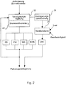
- Fig. 2 shows the schematic system structure of a device for controlling or regulating a brake system for performing rapid braking using several brake systems.
- the control or regulating device has a signal input for reading in a rapid braking request.
- a deceleration control 20 and a braking force distribution 22 cooperate to control the various in Fig. 2 shown brake systems (pneumatic brake PN, electrodynamic brake ED, magnetic rail brake EG, Eddy Current Brake ECB).
- the braking system of the rail vehicle has either all of the in Fig. 2 brake systems shown, or part of these brake systems.
- Air brakes also known as pneumatic brakes (PN)
- PN pneumatic brakes
- rail vehicles in particular traction vehicles, also have magnetic rail brakes (MG) and electrodynamic brakes (ED) in electric and diesel-electric vehicles, or hydraulic or retarder brakes in diesel-hydraulic vehicles.
- Newer vehicles, especially high-speed traction vehicles are also equipped with so-called Eddy Current Brakes (ECB).
- the safety-relevant brake system is a pneumatic brake (PN).
- Pneumatic brakes are usually available in rail vehicles. They are simply constructed and meet the corresponding requirements with regard to the safety assessment. In particular, pneumatic brakes can be used to delay the vehicle to a standstill. When performing rapid braking, the pressure of the pneumatic brake (PN) can be controlled or regulated on the basis of the speed, the load, or both variables.
- This pressure control or regulation is possible on the one hand if the pneumatic brake only interacts with the other brake systems in order to carry out the rapid braking, but in particular also then, if the rapid braking is continued using only the pneumatic braking system as a safety-relevant braking system after the total braking force of the vehicle has been judged to be too low or too high.
- a maximum deceleration can be achieved during the rapid braking with the pneumatic brake by speed or load-dependent pressure control of the pneumatic brake.
- the braking force distribution 22 specifies what proportion of the braking torque is to be contributed by the respective braking system. For this, the execution according to Fig. 2 For example, the braking forces of the braking systems involved in rapid braking can be regulated. As a result, the total braking force can be divided between the individual braking systems. In particular, the lowest possible braking torque is applied to wearing brake systems, for example the pneumatic brake (PN), while wear-free brakes, such as the electrodynamic brake (ED), provide the maximum possible braking torque.
- the deceleration control 20 initially specifies the required deceleration of the system and thus the required total braking force, which is then converted into braking torque requests for the individual systems by the braking force distribution 22.
- the vehicle decelerates due to the individual braking torques from the individual braking systems.
- the deceleration of the vehicle is measured and observed in the deceleration control 20.
- the deceleration monitor 24 checks whether the deceleration achieved is sufficiently high to meet the requirements for rapid braking or whether the deceleration achieved is too low or too high. If the latter is the case, a fall-back level 26 is activated, by means of which the further brake systems are deactivated and the braking is carried out exclusively by the pneumatic brake PN.
- the pneumatic brake is activated in the fallback level 26 in the in Fig. 2 shown device depending on the current load and the current speed of the vehicle.
Description
Die vorliegende Erfindung betrifft ein Verfahren und eine Vorrichtung zur Steuerung oder Regelung einer Bremsanlage, insbesondere einer Bremsanlage eines Schienenfahrzeugs. Die Erfindung betrifft ferner eine Bremsanlage, insbesondere eine Bremsanlage eines Schienenfahrzeugs, mit einer solchen Steuerungs- oder Regelungsvorrichtung.The present invention relates to a method and a device for controlling or regulating a brake system, in particular a brake system of a rail vehicle. The invention further relates to a brake system, in particular a brake system of a rail vehicle, with such a control or regulating device.
Bremsanlagen von Schienenfahrzeugen weisen in der Regel mehrere verschiedene Bremssysteme auf. In nahezu allen Schienenfahrzeugen sind Druckluftbremsen, auch als pneumatische Bremsen (PN) bezeichnet, im Einsatz. Daneben weisen Schienenfahrzeuge, insbesondere Triebfahrzeuge, auch Magnetschienenbremsen (MG) und bei elektrischen und dieselelektrischen Fahrzeugen elektrodynamische Bremsen (ED) bzw. bei dieselhydraulischen Fahrzeugen hydraulische bzw. Retarderbremsen auf. Neuere Fahrzeuge, insbesondere Triebfahrzeuge des Hochgeschwindigkeitsverkehrs, werden auch mit sogenannten Eddy Current Brakes (ECB) ausgerüstet.Braking systems of rail vehicles usually have several different braking systems. Air brakes, also known as pneumatic brakes (PN), are used in almost all rail vehicles. In addition, rail vehicles, in particular traction vehicles, also have magnetic rail brakes (MG) and, in the case of electric and diesel-electric vehicles, electrodynamic brakes (ED) or, in the case of diesel-hydraulic vehicles, hydraulic or retarder brakes. Newer vehicles, especially high-speed traction vehicles, are also equipped with so-called Eddy Current Brakes (ECB).
Beim Bremsen von Schienenfahrzeugen wird zwischen verschiedenen Arten der Bremsung unterschieden. So wird beispielsweise eine Betriebsbremsung durch den Triebfahrzeugführer oder durch automatische Steuerungen eingeleitet. Die Betriebsbremse ist hinsichtlich Lebenszykluskosten, Komfort und ökologischen Gesichtspunkten (maximale Nutzung der rekuperativen elektrodynamischen Bremse) optimiert. Deswegen werden während einer Betriebsbremsung vorrangig verschleißfreie Bremssysteme, wie die elektrodynamische Bremse, eingesetzt.When braking rail vehicles, a distinction is made between different types of braking. For example, service braking is initiated by the driver or by automatic controls. The service brake is optimized with regard to life cycle costs, comfort and ecological aspects (maximum use of the recuperative electrodynamic brake). That is why wear-free brake systems, such as the electrodynamic brake, are primarily used during service braking.
Schnellbremsungen werden hingegen durch den Triebfahrzeugführer im Gefahrenfall eingeleitet. Dabei werden verkürzte Ansprechzeiten gefordert. Es werden die Bremsen mit der höchsten Verfügbarkeit eingesetzt. Daher kommen bei der Schnellbremsung, unter der nachfolgend auch eine Notbremsung, Zwangsbremsung oder Gefahrenbremsung verstanden werden soll, auch die Reibungsbremsen, wie beispielsweise die pneumatische Bremse/Druckluftbremse, und die Magnetschienenbremse zum Einsatz.Rapid braking, however, is initiated by the driver in the event of danger. Shorter response times are required. The brakes with the highest availability are used. Therefore, in the case of rapid braking, which in the following is also to be understood as emergency braking, emergency braking or emergency braking, the friction brakes, such as for example the pneumatic brake / compressed air brake and the magnetic rail brake.
Die für die Schnellbremsung verwendeten Bremssysteme müssen hohe Anforderungen hinsichtlich der Sicherheitsbewertung erfüllen. Viele Funktionen der Betriebsbremse können deshalb während der Schnellbremse nicht genutzt werden, da sie die entsprechenden Anforderungen hinsichtlich der Sicherheitsbewertung nicht erfüllen. Die Nutzung der Betriebsbremsfunktionen während der Schnellbremse bei gleichzeitiger Sicherstellung der geforderten Sicherheit bringt jedoch erheblich ökonomische und auch ökologische Vorteile. Diese werden insbesondere, aber nicht ausschließlich, bei Hochgeschwindigkeitszügen erzielt, wo die zum Bremsen des Fahrzeugs notwendige Energie und der dabei auftretende Verschleiß hoch ist und somit die ökonomischen und ökologischen Vorteile der Nutzung verschleißfreier Bremsen auch in der Schnellbremsung besonders hoch sind.The braking systems used for rapid braking must meet high safety assessment requirements. Many functions of the service brake can therefore not be used during the quick brake because they do not meet the corresponding requirements with regard to the safety assessment. However, the use of the service brake functions during rapid braking while ensuring the required safety brings considerable economic and ecological advantages. These are achieved in particular, but not exclusively, in high-speed trains, where the energy required to brake the vehicle and the wear that occurs are high, and the economic and ecological advantages of using wear-free brakes are also particularly high in rapid braking.
In herkömmlichen Bremsanlagen werden die Bremssysteme für eine Schnellbremsung so angesteuert, dass die sicherheitsrelevante Reibungsbremse aktiviert wird und die weiteren Bremssysteme, die nur für niedrigere Sicherheitsanforderungen ausgelegt sind, deaktiviert werden. Dadurch wird ein hohes Sicherheitsniveau garantiert. Das Bremsmoment wird dadurch jedoch ausschließlich durch die einem Verschleiß unterworfene Reibungsbremse erzeugt. Die verschleißarmen Bremssysteme sind hingegen deaktiviert. Dadurch wird einerseits ein hoher Verschleiß erzeugt, und andererseits ist es nicht möglich, die Bremsenergie rückzugewinnen.In conventional brake systems, the brake systems for rapid braking are activated in such a way that the safety-relevant friction brake is activated and the other brake systems, which are only designed for lower safety requirements, are deactivated. This guarantees a high level of security. However, the braking torque is generated exclusively by the friction brake that is subject to wear. The low-wear brake systems, however, are deactivated. On the one hand, this creates a high level of wear and, on the other hand, it is not possible to recover the braking energy.
Aus der
Der Erfindung liegt daher die Aufgabe zugrunde, ein verbessertes Verfahren und eine verbesserte Vorrichtung zur Steuerung oder Regelung einer Bremsanlage bereitzustellen, die einen möglichst verschleißarmen Betrieb der Bremsanlage während einer Schnellbremsung ermöglichen.The invention is therefore based on the object of providing an improved method and an improved device for controlling or regulating a brake system, which enable the brake system to be operated with as little wear as possible during rapid braking.
Die Aufgabe wird durch ein Verfahren zur Steuerung oder Regelung einer Bremsanlage mit den Verfahrensschritten des Anspruchs 1 sowie durch eine Vorrichtung zur Steuerung oder Regelung einer Bremsanlage mit den Merkmalen des Anspruchs 8 und durch ein Schienenfahrzeug mit den Merkmalen des Anspruchs 14 gelöst. Weitere Merkmale der Erfindung ergeben sich aus den Unteransprüchen.The object is achieved by a method for controlling or regulating a brake system with the method steps of claim 1 and by a device for controlling or regulating a brake system with the features of claims 8 and solved by a rail vehicle with the features of
Ein erfindungsgemäßes Verfahren zur Steuerung oder Regelung einer Bremsanlage, insbesondere einer Bremsanlage eines Schienenfahrzeuges, die wenigstens ein sicherheitsrelevantes Bremssystem und wenigstens ein weiteres Bremssystem aufweist, liest zunächst eine der Bremsanlage vorgegebene Schnellbremsanforderung ein. Aufgrund der Schnellbremsanforderung leitet das Verfahren dann eine Schnellbremsung ein, wobei das weitere Bremssystem verwendet wird. Die Gesamtbremskraft des Schienenfahrzeugs wird überwacht, und es wird überprüft, ob die Gesamtbremskraft einen Schwellwert unterschreitet oder überschreitet. Unterschreitet oder überschreitet die Gesamtbremskraft einen Schwellwert, so wird die Schnellbremsung unter ausschließlicher Verwendung des sicherheitsrelevanten Bremssystems weitergeführt.A method according to the invention for controlling or regulating a brake system, in particular a brake system of a rail vehicle, which has at least one safety-relevant brake system and at least one further brake system, first reads in a rapid brake request specified for the brake system. The method then initiates rapid braking on the basis of the rapid braking request, the further braking system being used. The total braking force of the rail vehicle is monitored and it is checked whether the total braking force falls below or exceeds a threshold value. If the total braking force falls below or exceeds a threshold value, rapid braking is continued using only the safety-relevant braking system.
Das sicherheitsrelevante Bremssystem ist bei Schienenfahrzeugen vorzugsweise ein pneumatisches Bremssystem (PN), d. h. die allgemein vorhandene Druckluftbremse. Es können neben dem sicherheitsrelevanten Bremssystem ein oder mehrere weitere Bremssysteme vorhanden sein. Die weiteren Bremssysteme sind so ausgelegt, dass sie niedrigere Sicherheitsanforderungen erfüllen als das sicherheitsrelevante Bremssystem. Die weiteren Bremssysteme sind beispielsweise eine elektrodynamische Bremse, eine Magnetschienenbremse oder eine Eddy Current Brake (ECB). Für eine Vielzahl von Triebfahrzeugen ist beispielsweise das Vorhandensein einer Magnetschienenbremse vorgeschrieben. Bei Dieselfahrzeugen kann, wenn es sich um ein dieselhydraulisches Fahrzeug handelt, statt einer elektrodynamischen Bremse eine hydraulische Bremse, beispielsweise eine Retarderbremse, eingesetzt werden.The safety-relevant brake system in rail vehicles is preferably a pneumatic brake system (PN), i. H. the generally available air brake. In addition to the safety-relevant braking system, one or more further braking systems can be present. The other brake systems are designed in such a way that they meet lower safety requirements than the safety-relevant brake system. The other brake systems are, for example, an electrodynamic brake, a magnetic rail brake or an Eddy Current Brake (ECB). For example, the presence of a magnetic rail brake is mandatory for a large number of locomotives. In the case of diesel vehicles, if it is a diesel-hydraulic vehicle, a hydraulic brake, for example a retarder brake, can be used instead of an electrodynamic brake.
Das erfindungsgemäße Verfahren liest zunächst eine von außen vorgegebene Schnellbremsanforderung ein. Diese kann vom Triebfahrzeugführer ausgelöst werden, aber auch beispielsweise, wie z.B. bei Zwangsbremsungen, durch die Sicherheitsfahrschaltung oder Zugsicherungssysteme, wie Indusi. Aufgrund der von außen vorgegebenen Schnellbremsanforderung leitet das erfindungsgemäße Verfahren unmittelbar eine Schnellbremsung ein. Bei der Schnellbremsung wird das weitere Bremssystem verwendet. Dabei kann das weitere Bremssystem zunächst überwiegend oder ausschließlich eingesetzt werden, oder es wird zusätzlich und unterstützend zum sicherheitsrelevanten Bremssystem eingesetzt. Dabei wird, wenn das sicherheitsrelevante Bremssystem eine pneumatische Bremse ist, eine Druckregelung der pneumatischen Bremse durchgeführt, um die Bremskraft zu verteilen und soweit wie möglich mit dem weiteren Bremssystem, insbesondere mit einem verschleißfreien weiteren Bremssystem, zu bremsen. Da beispielsweise die elektrodynamische Bremse nicht bis zu einem Stillstand des Fahrzeuges herunterbremst und ihr Bremsmoment mit abnehmender Geschwindigkeit sinkt, kann es erforderlich sein, die Bremsmomente der verschiedenen Bremssysteme beispielsweise in Abhängigkeit von Geschwindigkeit und Lasten zu steuern und damit eine geeignete Bremskraftverteilung herbeizuführen, um jederzeit eine optimale Gesamtbremskraft zu erzielen.The method according to the invention first reads in an external rapid braking request. This can be triggered by the driver, but also, for example, as in the case of emergency braking, by means of the safety driving circuit or train protection systems such as Indusi. On the basis of the rapid braking request specified from the outside, the method according to the invention immediately initiates rapid braking. In the case of rapid braking, that will be further Brake system used. The further braking system can initially be used predominantly or exclusively, or it is used in addition and in support of the safety-relevant braking system. If the safety-relevant brake system is a pneumatic brake, pressure control of the pneumatic brake is carried out in order to distribute the braking force and to brake as far as possible with the further brake system, in particular with a wear-free further brake system. For example, since the electrodynamic brake does not brake until the vehicle comes to a standstill and its braking torque decreases with decreasing speed, it may be necessary to control the braking torques of the various braking systems depending on the speed and loads, for example, and thus to bring about a suitable braking force distribution in order to achieve a braking force at all times to achieve optimal total braking force.
Während der Schnellbremsung wird die Gesamtbremskraft des Schienenfahrzeugs überwacht. Dazu werden Informationen über den Fahrzeugzustand, die beispielsweise messtechnisch erfasst werden können, verarbeitet, um aus ihnen Rückschlüsse über die Gesamtbremskraft des Fahrzeugs zu schließen. Es wird dann überprüft, ob die Gesamtbremskraft des Fahrzeuges einen vorgegebenen Schwellwert unterschreitet oder einen vorgegebenen Schwellwert überschreitet. Dieser Schwellwert kann konstant, er kann aber auch beispielsweise geschwindigkeitsabhängig sein. Es kann sich beim Schwellwert um einen einzigen Schwellwert, vorzugsweise jedoch um zwei voneinander verschiedene Schwellwerte handeln, von denen ein erster Schwellwert für das Unterschreiten durch die Gesamtbremskraft relevant ist, und ein zweiter Schwellwert für das Überschreiten durch die Gesamtbremskraft.The total braking force of the rail vehicle is monitored during rapid braking. For this purpose, information about the state of the vehicle, which can be measured, for example, is processed in order to draw conclusions about the total braking force of the vehicle. It is then checked whether the total braking force of the vehicle falls below a predetermined threshold value or exceeds a predetermined threshold value. This threshold value can be constant, but it can also be speed-dependent, for example. The threshold value can be a single threshold value, but preferably two different threshold values, of which a first threshold value is relevant for falling below the total braking force and a second threshold value for exceeding the total braking force.
Sind die Schwellwerte voneinander verschieden, so wird ein Bereich zwischen den beiden Schwellwerten gebildet, in dem die Gesamtbremskraft liegen muss, um eine Bremsung unter Verwendung des oder der weiteren Bremssysteme durchzuführen. Liegt die Gesamtbremskraft hingegen unterhalb des kleineren der beiden Schwellwerte, so ist die Gesamtbremskraft, die unter Verwendung wenigstens eines der weiteren Bremssysteme erzielt wird, zu niedrig, so dass die Schnellbremsung unter ausschließlicher Verwendung des sicherheitsrelevanten Bremssystems fortgeführt wird, um eine ausreichende Bremskraft zu erzielen.If the threshold values are different from one another, a range is formed between the two threshold values in which the total braking force must be in order to carry out braking using the further braking system or systems. If, on the other hand, the total braking force is below the smaller of the two threshold values, the total braking force that is achieved using at least one of the other braking systems is too low, so that rapid braking is continued using only the safety-relevant braking system in order to achieve a sufficient braking force.
Liegt die Gesamtbremskraft hingegen oberhalb des größeren der beiden Schwellwerte, so ist die Gesamtbremskraft, die unter Verwendung wenigstens eines der weiteren Bremssysteme erzielt wird, zu hoch, so dass die Schnellbremsung ebenfalls unter ausschließlicher Verwendung des sicherheitsrelevanten Bremssystems fortgeführt wird. Dadurch kann verhindert werden, dass eine Kraftschlussausnutzung beispielsweise zwischen Rad und Schiene überschritten wird und es beispielsweise zu einem Gleiten kommen kann.If, on the other hand, the total braking force is above the larger of the two threshold values, the total braking force that is achieved using at least one of the other braking systems is too high, so that rapid braking is also continued using only the safety-relevant braking system. This can prevent the adhesion utilization, for example between the wheel and the rail, from being exceeded and, for example, from slipping.
Der Verwendung zweier voneinander verschiedener Schwellwerte mit einem zwischen den beiden Schwellwerten angeordneten Wertebereich entspricht die Verwendung eines einzelnen Schwellwerts, der jedoch von einem Hysteresebereich umgeben ist
Unterschreitet oder überschreitet die Gesamtbremskraft des Fahrzeuges den Schwellwert oder die jeweiligen Schwellwerte, dann wird die Schnellbremsung unter ausschließlicher Verwendung des sicherheitsrelevanten Bremssystems fortgeführt. Dabei wird die Bremsmomentanforderung an das sicherheitsrelevante Bremssystem, in der Regel an die pneumatische Bremse, erhöht. Die weiteren Bremssysteme des Fahrzeuges werden dann deaktiviert und nicht mehr zur Weiterführung der Schnellbremsung eingesetzt. Es wird damit, wenn die Gesamtbremskraft den oder die Schwellwerte unterschreitet oder überschreitet, auf einen zweiten, unabhängigen Bremsmodus geschaltet, welcher der herkömmlichen Schnellbremse entspricht.The use of two different threshold values with a range of values arranged between the two threshold values corresponds to the use of a single threshold value, which is, however, surrounded by a hysteresis range
If the total braking force of the vehicle falls below or exceeds the threshold value or the respective threshold values, then the rapid braking is continued using only the safety-relevant braking system. The braking torque requirement on the safety-relevant braking system, usually on the pneumatic brake, is increased. The other braking systems of the vehicle are then deactivated and are no longer used to continue rapid braking. When the total braking force falls below or exceeds the threshold value or values, it is switched to a second, independent braking mode which corresponds to the conventional rapid braking.
Das erfindungsgemäße Verfahren zur Steuerung oder Regelung einer Bremsanlage ermöglicht die Nutzbarkeit der Betriebsbremsfunktionen bzw. der weiteren Bremssysteme, die während einer Betriebsbremsung eingesetzt werden, auch während der Schnellbremse. Dadurch kann der Verschleiß der Bremssysteme reduziert werden, und eine Rückgewinnung von Bremsenergie wird möglich. Dabei wird gleichzeitig die Sicherheitsintegrität der Schnellbremse sichergestellt, so dass die Sicherheitsanforderungen an das System zur Durchführung der Schnellbremsung erfüllt werden, obwohl einzelne Komponenten, die bei der Schnellbremsung verwendet werden können, die entsprechenden Anforderungen hinsichtlich der Sicherheitsbewertung nicht erfüllen.The method according to the invention for controlling or regulating a brake system enables the usability of the service brake functions or of the further brake systems which are used during service braking, even during the rapid brake. As a result, the wear of the brake systems can be reduced and braking energy can be recovered. At the same time, the safety integrity of the rapid brake is ensured, so that the safety requirements for the system for carrying out the rapid braking are fulfilled, although individual components which can be used in the rapid braking do not meet the corresponding requirements with regard to the safety assessment.
In einer weiteren Ausgestaltung des Verfahrens erfolgt das Überwachen der Gesamtbremskraft des Fahrzeuges durch Messen der Gesamtverzögerung in Fahrzeugrichtung. Die Verzögerung des Fahrzeuges ist eine einfach bestimmbare Größe, aus der auf die Gesamtbremskraft zurückgeschlossen werden kann. Dabei wird die Gesamtverzögerung vorzugsweise in Fahrtrichtung durch einen Beschleunigungssensor gemessen. Dies hat den Vorteil, dass das System auch in Steigungen und Gefällen die korrekte Bremskraft überprüfen kann, während Systeme, die sich auf die kinematische Längsverzögerung des Fahrzeuges stützen, um die Gesamtverzögerung des Fahrzeugs in Fahrtrichtung zu bestimmen, zu Abweichungen zur tatsächlichen Bremskraft in Steigungen und Gefällen führen können. Dabei kann einer, oder es können auch mehrere Beschleunigungssensoren im Fahrzeug angeordnet sein.In a further embodiment of the method, the total braking force of the vehicle is monitored by measuring the total deceleration in the direction of the vehicle. The deceleration of the vehicle is an easily determinable quantity from which the total braking force can be deduced. The total deceleration is preferably measured in the direction of travel by an acceleration sensor. This has the advantage that the system can check the correct braking force even on uphill and downhill gradients, while systems that rely on the kinematic longitudinal deceleration of the vehicle to determine the total deceleration of the vehicle in the direction of travel lead to deviations from the actual braking force on inclines and Can lead slopes. One or more acceleration sensors can be arranged in the vehicle.
In einer weiteren vorteilhaften Ausgestaltung des Verfahrens ist das sicherheitsrelevante Bremssystem eine pneumatische Bremse. Pneumatische Bremsen sind in Schienenfahrzeugen in der Regel vorhanden. Sie sind einfach aufgebaut und erfüllen die entsprechenden Anforderungen hinsichtlich der Sicherheitsbewertung. Insbesondere kann mit pneumatischen Bremsen eine Verzögerung des Fahrzeugs bis zum Stillstand erreicht werden.In a further advantageous embodiment of the method, the safety-relevant brake system is a pneumatic brake. Pneumatic brakes are usually available in rail vehicles. They are simply constructed and meet the corresponding requirements with regard to the safety assessment. In particular, pneumatic brakes can be used to decelerate the vehicle to a standstill.
In einer weiteren vorteilhaften Ausgestaltung des Verfahrens kann bei der Durchführung der Schnellbremsung der Druck der pneumatischen Bremse anhand der Geschwindigkeit, der Last, oder beider Größen gesteuert oder geregelt werden. Diese Drucksteuerung bzw. -regelung ist einerseits dann möglich, wenn die pneumatische Bremse lediglich mit den anderen Bremssystemen zusammenwirkt, um die Schnellbremsung durchzuführen, aber insbesondere auch dann, wenn die Schnellbremsung unter ausschließlicher Verwendung des pneumatischen Bremssystems als sicherheitsrelevantem Bremssystem fortgeführt wird, nachdem die Gesamtbremskraft des Fahrzeuges als zu niedrig oder als zu hoch beurteilt wurde. Durch geschwindigkeits- oder lastabhängige Druckregelung der pneumatischen Bremse kann während der Schnellbremsung mit der pneumatischen Bremse eine maximale Verzögerung erzielt werden.In a further advantageous embodiment of the method, the pressure of the pneumatic brake can be controlled or regulated on the basis of the speed, the load or both variables when carrying out the rapid braking. This pressure control or regulation is possible on the one hand if the pneumatic brake only interacts with the other brake systems in order to carry out the rapid braking, but in particular also if the rapid braking is continued with the exclusive use of the pneumatic braking system as a safety-relevant braking system after the total braking force of the vehicle was judged to be too low or too high. A maximum deceleration can be achieved during the rapid braking with the pneumatic brake by speed or load-dependent pressure control of the pneumatic brake.
In einer vorteilhaften Ausgestaltung der Erfindung ist das weitere Bremssystem in der Bremsanlage eine elektrodynamische Bremse (ED), eine Magnetschienenbremse (MG) oder eine Eddy Current Brake (ECB). Bei diesen hydraulischen Fahrzeugen kann auch eine hydraulische Bremse, beispielsweise ein Retarder, verwendet werden.In an advantageous embodiment of the invention, the further brake system in the brake system is an electrodynamic brake (ED), a magnetic rail brake (MG) or an Eddy Current Brake (ECB). A hydraulic brake, for example a retarder, can also be used in these hydraulic vehicles.
In einer weiteren vorteilhaften Ausgestaltung des erfindungsgemäßen Verfahrens wird eine Regelung der Bremskraft der an Schnellbremsung beteiligten Bremssysteme vorgenommen. Dadurch kann die Bremskraft zwischen den einzelnen Bremssystemen aufgeteilt werden. Vorzugsweise werden dabei verschleißende Bremssysteme, beispielsweise die pneumatische Bremse, mit einem möglichst niedrigen Bremsmoment beaufschlagt, während verschleißfreie Bremsen, wie beispielsweise die elektrodynamische Bremse, ein maximal mögliches Bremsmoment bereitstellen.In a further advantageous embodiment of the method according to the invention, the braking force of the braking systems involved in rapid braking is regulated. As a result, the braking force can be divided between the individual braking systems. Wearable brake systems, for example the pneumatic brake, are preferably subjected to the lowest possible braking torque, while wear-free brakes, such as the electrodynamic brake, provide a maximum possible braking torque.
Eine erfindungsgemäße Vorrichtung zur Steuerung oder Regelung einer Bremsanlage, insbesondere einer Bremsanlage eines Schienenfahrzeuges, weist wenigstens ein sicherheitsrelevantes Bremssystem und wenigstens ein weiteres Bremssystem auf. Sie weist des Weiteren einen Signaleingang zum Einlesen einer Schnellbremsanforderung auf. Sie weist ferner eine Einrichtung zum Durchführen einer Schnellbremsung unter Verwendung mehrerer Bremssysteme auf. Die Vorrichtung weist des Weiteren eine Einrichtung zum Überwachen der Gesamtbremskraft des Schienenfahrzeuges und eine Einrichtung zum Überprüfen der Gesamtbremskraft auf das Unterschreiten oder Überschreiten eines oder mehrerer Schwellwerte auf. Des Weiteren weist die Vorrichtung eine Einrichtung zum Durchführen der Schnellbremsung unter ausschließlicher Verwendung des sicherheitsrelevanten Bremssystems auf.A device according to the invention for controlling or regulating a brake system, in particular a brake system of a rail vehicle, has at least one safety-relevant brake system and at least one further brake system. It also has a signal input for reading in a quick brake request. It also has a device for carrying out rapid braking using a plurality of braking systems. The device also has a device for monitoring the total braking force of the rail vehicle and a device for checking the total braking force for falling below or exceeding one or more threshold values. Furthermore, the device has a device for performing the rapid braking using only the safety-relevant braking system.
Die Signaleinrichtung liest ein Signal ein, durch das von außen eine Schnellbremsanforderung vorgegeben wird. Die Schnellbremsanforderung kann von dem Fahrzeugführer, aber auch vom Fahrzeug selber kommen, beispielsweise durch die Indusi bei Einleitung einer Zwangsbremsung.The signaling device reads in a signal by means of which a rapid braking request is specified from the outside. The quick brake request can come from the vehicle driver, but also from the vehicle itself, for example by the Indusi when an emergency braking application is initiated.
Die Einrichtung zum Durchführen einer Schnellbremsung unter Verwendung mehrerer Bremssysteme steuert aufgrund der Schnellbremsanforderung die vorhandenen Bremssysteme an. Dabei wird die Bremskraft auf die verschiedenen vorhandenen Systeme verteilt. Vorzugsweise wird die Bremskraft dabei so verteilt, dass das Bremsmoment so weit wie möglich durch verschleißfreie Bremsen, beispielsweise eine elektrodynamische Bremse, aufgebracht wird, während Reibungsbremsen, insbesondere die pneumatische Bremse, nach Möglichkeit nicht angesteuert werden oder nur ein geringes Bremsmoment aufbringen. Dies hängt auch vom jeweiligen Fahrzeugzustand ab, da elektrodynamische Bremsen bei geringeren Geschwindigkeiten ein geringeres Bremsmoment aufbringen, so dass das mit abnehmender Geschwindigkeit fallende Bremsmoment durch Erhöhen des Bremsmoments durch die pneumatische Bremse kompensiert werden muss.The device for carrying out rapid braking using a plurality of braking systems controls the existing braking systems on the basis of the rapid braking request. The braking force is applied to the different ones Systems distributed. The braking force is preferably distributed in such a way that the braking torque is applied as far as possible by wear-free brakes, for example an electrodynamic brake, while friction brakes, in particular the pneumatic brake, are not activated if possible or only apply a small braking torque. This also depends on the respective vehicle condition, since electrodynamic brakes apply a lower braking torque at lower speeds, so that the braking torque, which decreases with decreasing speed, must be compensated for by increasing the braking torque by means of the pneumatic brake.
Die Einrichtung zum Überwachen der Gesamtbremskraft des Fahrzeuges überwacht den Fahrzeugzustand, insbesondere die Verzögerung des Fahrzeuges, und bestimmt aus dieser die Bremskraft. Dies kann durch Sensoren und Fahrzeugmodelle erfolgen.The device for monitoring the total braking force of the vehicle monitors the vehicle condition, in particular the deceleration of the vehicle, and determines the braking force from this. This can be done using sensors and vehicle models.
In einer weiteren Einrichtung der Vorrichtung wird überprüft, ob die derart bestimmte Gesamtbremskraft einen oder verschiedene Schwellwerte unterschreitet oder überschreitet. Unterschreitet oder überschreitet sie einen oder verschiedene Schwellwerte, so wird dieses an eine Einrichtung zum Durchführen der Schnellbremsung unter ausschließlicher Verwendung des sicherheitsrelevanten Bremssystems gemeldet. Diese Einrichtung deaktiviert die weiteren Bremssysteme und führt die Sicherheitsbremsung ausschließlich unter Verwendung des sicherheitsrelevanten Bremssystems durch.Another device of the device checks whether the total braking force determined in this way falls below or exceeds one or different threshold values. If it falls below or exceeds one or different threshold values, this is reported to a device for performing the rapid braking using only the safety-relevant braking system. This device deactivates the other brake systems and carries out the safety braking exclusively using the safety-relevant brake system.
Eine im Sinne der Erfindung ausgebildete Vorrichtung zur Steuerung oder Regelung einer Bremsanlage zeichnet sich vor allem dadurch aus, dass der Verschleiß der Reibungsbremsen des Fahrzeuges soweit wie möglich reduziert wird, und gleichzeitig eine Bremsenergie-Rückgewinnung möglich wird.A device designed to control or regulate a brake system in the sense of the invention is characterized above all by the fact that the wear of the friction brakes of the vehicle is reduced as much as possible, and at the same time braking energy recovery is possible.
In einer weiteren Ausgestaltung der erfindungsgemäßen Vorrichtung weist die Einrichtung zum Überwachen der Gesamtbremskraft des Fahrzeuges einen Beschleunigungssensor auf. Durch diesen kann die Verzögerung des Fahrzeuges bestimmt werden. Die Verzögerung kann dabei insbesondere in Fahrtrichtung erfolgen, so dass auch bei Steigungs- oder Gefällefahrten stets die Gesamtbremskraft richtig ermittelt wird. Zur Ermittlung der Gesamtbremskraft können Modelle des Fahrzeuges herangezogen werden.In a further embodiment of the device according to the invention, the device for monitoring the total braking force of the vehicle has an acceleration sensor. The deceleration of the vehicle can be determined by this. The deceleration can take place in particular in the direction of travel, so that the total braking force is always correct even when driving uphill or downhill is determined. Models of the vehicle can be used to determine the total braking force.
In einer weiteren vorteilhaften Ausgestaltung der Vorrichtung ist das sicherheitsrelevante Bremssystem eine pneumatische Bremse.In a further advantageous embodiment of the device, the safety-relevant brake system is a pneumatic brake.
In einer weiteren vorteilhaften Ausgestaltung der Vorrichtung ist das weitere Bremssystem eine elektrodynamische Bremse, eine Magnetschienenbremse oder eine Eddy Current Brake (ECB). Bei diesen hydraulischen Fahrzeugen kann auch eine hydraulische Bremse, beispielsweise ein Retarder, verwendet werden. Es können eines oder mehrere weitere Bremssysteme in der Vorrichtung eingesetzt werden.In a further advantageous embodiment of the device, the further brake system is an electrodynamic brake, a magnetic rail brake or an Eddy Current Brake (ECB). A hydraulic brake, for example a retarder, can also be used in these hydraulic vehicles. One or more further braking systems can be used in the device.
In einer weiteren vorteilhaften Ausgestaltung der Vorrichtung weist die Vorrichtung eine Einrichtung zum Verteilen der Bremskraft zwischen den an der Schnellbremsung beteiligten Bremssystemen auf. Dadurch kann das zum Durchführen der Schnellbremsung erforderliche Bremsmoment durch die verschiedenen Systeme erzeugt werden. Das Bremsmoment kann nach verschiedenen Optimalitätskriterien, beispielsweise Verschleiß, Bremsenergie-Rückgewinnung oder erforderlichem Bremsmoment, verteilt werden.In a further advantageous embodiment of the device, the device has a device for distributing the braking force between the brake systems involved in rapid braking. As a result, the braking torque required to carry out the rapid braking can be generated by the various systems. The braking torque can be distributed according to various optimality criteria, for example wear, braking energy recovery or the required braking torque.
In einer erfindungsgemäßen Bremsanlage wird eine Vorrichtung zur Steuerung oder Regelung einer Bremsanlage gemäß den vorstehend beschriebenen Ausgestaltungen eingesetzt.In a brake system according to the invention, a device for controlling or regulating a brake system according to the configurations described above is used.
In einem erfindungsgemäßen Schienenfahrzeug wird eine Vorrichtung zur Steuerung oder Regelung einer Bremsanlage gemäß den vorstehend beschriebenen Ausgestaltungen eingesetzt.In a rail vehicle according to the invention, a device for controlling or regulating a brake system according to the configurations described above is used.
Ausführungsbeispiele der Erfindung werden nachfolgend anhand der beigefügen Zeichnungen beschrieben.Embodiments of the invention are described below with reference to the accompanying drawings.
Es zeigen:
- Fig. 1:
- den Ablauf eines erfindungsgemäßen Verfahrens zur Steuerung oder Regelung einer Bremsanlage; und
- Fig. 2:
- eine Vorrichtung zur Steuerung oder Regelung einer Bremsanlage.
- Fig. 1:
- the sequence of a method according to the invention for controlling or regulating a brake system; and
- Fig. 2:
- a device for controlling or regulating a brake system.
Das Verfahren zur Steuerung oder Regelung einer Bremsanlage erhält von außen, beispielsweise vom Triebfahrzeugführer oder von den Fahrzeugsystemen oder den Zugsicherungssystemen, wie beispielsweise durch die Sicherheitsfahrschaltung oder die Indusi, eine Schnellbremsanforderung vorgegeben. Diese wird zunächst im ersten Verfahrensschritt erfasst (S10). Daraufhin wird unmittelbar eine Schnellbremsung eingeleitet (S12). Dabei werden neben dem sicherheitsrelevanten Bremssystem, üblicherweise dem pneumatischen Bremssystem, eines oder mehrere weitere Bremssysteme, die während der Betriebsbremsung verwendet werden, eingesetzt. Die weiteren Bremssysteme sind so ausgelegt, dass sie niedrigere Sicherheitsanforderungen erfüllen als das sicherheitsrelevante Bremssystem. Diese Bremssysteme werden angesteuert, und es wird für die verschiedenen Bremssysteme das durch das Bremssystem jeweils aufzubringende Bremsmoment vorgegeben. Dabei kann das weitere Bremssystem bzw. die weiteren Bremssysteme zunächst überwiegend oder ausschließlich eingesetzt werden, oder es wird bzw. sie werden zusätzlich und unterstützend zum sicherheitsrelevanten Bremssystem eingesetzt. Das Fahrzeug führt dann eine Schnellbremsung durch.The method for controlling or regulating a brake system receives a rapid braking request from the outside, for example from the driver or from the vehicle systems or the train protection systems, such as, for example, by the safety driving circuit or the indusi. This is first recorded in the first method step (S10). Rapid braking is then initiated immediately (S12). In addition to the safety-relevant brake system, usually the pneumatic brake system, one or more further brake systems that are used during service braking are used. The other brake systems are designed in such a way that they meet lower safety requirements than the safety-relevant brake system. These brake systems are controlled and the braking torque to be applied by the brake system is specified for the various brake systems. In this case, the further brake system or the further brake systems can initially be used predominantly or exclusively, or it is or are used in addition and in support of the safety-relevant brake system. The vehicle then brakes quickly.
Wenn das sicherheitsrelevante Bremssystem eine pneumatische Bremse ist, wird eine Druckregetung der pneumatischen Bremse durchgeführt, um die Bremskraft zu verteilen und soweit wie möglich mit dem weiteren Bremssystem bzw. den weiteren Bremssystemen, insbesondere mit einem verschleißfreien weiteren Bremssystem, zu bremsen. Da beispielsweise die in
Während der Schnellbremsung wird der Fahrzeugzustand erfasst (S14). Dafür wird beispielsweise mittels eines Beschleunigungssensors die Fahrzeugverzögerung ermittelt. Aus der Fahrzeugverzögerung wird die Gesamtbremskraft des Fahrzeuges ermittelt. Das Überwachen der Gesamtbremskraft des Fahrzeuges kann insbesondere durch Messen der Gesamtverzögerung in Fahrzeugrichtung erfolgen. Aus der Verzögerung des Fahrzeuges, die einfach mit der vorhandenen Sensorik des Fahrzeugs ermittelt werden kann, kann somit auf die Gesamtbremskraft zurückgeschlossen werden. Dabei wird die Gesamtverzögerung insbesondere in Fahrtrichtung durch einen meist serienmäßig im Fahrzeug vorhandenen Beschleunigungssensor gemessen.The vehicle state is detected during rapid braking (S14). For this purpose, the vehicle deceleration is determined, for example, using an acceleration sensor. The total braking force of the vehicle is determined from the vehicle deceleration. The total braking force of the vehicle can be monitored in particular by measuring the total deceleration in the direction of the vehicle. The total braking force can thus be deduced from the deceleration of the vehicle, which can easily be determined using the existing sensor system of the vehicle. The total deceleration, in particular in the direction of travel, is measured by an acceleration sensor that is usually standard in the vehicle.
Die ermittelte Gesamtbremskraft wird im nachfolgenden Schritt (S16) überwacht. Es wird überprüft, ob die ermittelte Gesamtbremskraft einen vorgegebenen Schwellwert unterschreitet oder überschreitet (S18). Dieser Schwellwert kann festgelegt sein, und es kann sich um voneinander verschiedene Schwellwerte handeln. Der oder die Schwellwerte können jedoch auch vom Fahrzeugzustand, beispielsweise der Fahrzeuggeschwindigkeit oder dem Fahrzeuggewicht abhängig sein.
Ist die Gesamtbremskraft nicht kleiner oder größer als der oder die vorgegebenen Schwellwerte, so wird die Schnellbremsung weiterhin unter Verwendung der mehreren Bremssysteme durchgeführt (S12).The total braking force determined is monitored in the subsequent step (S16). It is checked whether the total braking force determined falls below or exceeds a predetermined threshold value (S18). This threshold value can be fixed and the threshold values can be different from one another. However, the threshold value (s) can also depend on the vehicle condition, for example the vehicle speed or the vehicle weight.
If the total braking force is not less than or greater than the predetermined threshold value (s), rapid braking is still carried out using the multiple braking systems (S12).
Ist die Gesamtbremskraft hingegen unzureichend, d.h. unterschreitet die Gesamtbremskraft einen Schwellwert, da die Fahrzeugverzögerung nicht ausreichend ist, so wird die Schnellbremsung ausschließlich mit dem sicherheitsrelevanten Bremssystem durchgeführt (S20). Dies ist auch der Fall, wenn die Gesamtbremskraft zu hoch ist. Die weiteren Bremssysteme werden dafür abgeschaltet, und das Bremsmoment wird nur durch das sicherheitsrelevante Bremssystem bereitgestellt. Durch das Steuerung- oder Regelungsverfahren wird dabei das durch das sicherheitsrelevante Bremssystem bereitgestellte Bremsmoment so angepasst, dass eine maximale bzw. eine für die Schnellbremsung geforderte Verzögerung des Fahrzeugs erreicht wird.If, on the other hand, the total braking force is insufficient, ie if the total braking force falls below a threshold value because the vehicle deceleration is not sufficient, rapid braking is carried out exclusively with the safety-relevant braking system (S20). This is also the case if the total braking force is too high. The other brake systems are switched off for this, and the braking torque is only provided by the safety-relevant brake system. Through the control or regulation process, this is through the Safety-relevant braking system provided braking torque adjusted so that a maximum or a deceleration of the vehicle required for rapid braking is achieved.
Die Steuerungs- oder Regelungsvorrichtung weist einen Signaleingang zum Einlesen einer Schnellbremsanforderung auf. Eine Verzögerungsregelung 20 und eine Bremskraftverteilung 22 wirken zusammen, um die verschiedenen in
In der in
Die Bremskraftverteilung 22 gibt dabei vor, welcher Anteil des Bremsmomentes durch das jeweilige Bremssystem beizusteuern ist. Dafür kann in der Ausführung gemäß
Aufgrund der einzelnen Bremsmomente durch die einzelnen Bremssysteme verzögert das Fahrzeug. Die Verzögerung des Fahrzeugs wird gemessen und in der Verzögerungsregelung 20 beobachtet. Durch die Verzögerungsüberwachung 24 wird überprüft, ob die erzielte Verzögerung ausreichend hoch ist, um die Anforderungen an die Schnellbremsung zu erfüllen, oder ob die erzielte Verzögerung zu niedrig oder zu hoch ist. Ist letzteres der Fall, so wird eine Rückfallebene 26 aktiviert, durch die die weiteren Bremssysteme deaktiviert werden und die Bremsung ausschließlich durch die pneumatische Bremse PN durchgeführt wird. Die Ansteuerung der pneumatischen Bremse erfolgt in der Rückfallebene 26 dabei in der in
- S10S10
- Einlesen der SchnellbremsanforderungRead the quick brake request
- S12S12
- Durchführen der SchnellbremsungPerform the rapid braking
- S14S14
- Erfassen des FahrzeugzustandsDetection of the vehicle condition
- S16S16
- Überwachen der GesamtbremskraftMonitor the total braking force
- S18S18
- Überprüfen der Gesamtbremskraft auf Schwellwertunter- oder überschreitungCheck the total braking force for falling below or exceeding the threshold value
- S20S20
- Fortführen der Schnellbremsung nur mit sicherheitsrelevantem BremssystemContinuation of the rapid braking only with a safety-relevant braking system
- 2020th
- VerzögerungsregelungDeceleration control
- 2222
- BremskraftverteilungBrake force distribution
- 2424th
- VerzögerungsüberwachungDelay monitoring
- 2626
- RückfallebeneFallback level
Claims (14)
- A method for controlling or regulating a brake system, in particular a brake system of a rail vehicle, the brake system having at least one safety-relevant brake system (PN) and at least one further brake system (ED, MG, ECB),
characterized by the following steps:inputting of a rapid brake request (S10),carrying out of a rapid brake operation using at least one of the further brake systems (S20),monitoring of the overall brake force of the vehicle (S16),checking whether the overall brake force undershoots or exceeds a threshold value (S18),continuation of the rapid brake operation with exclusive use of the safety-relevant brake system (S20) if the threshold value is undershot or exceeded. - The method as claimed in claim 1,
the monitoring of the overall brake force of the vehicle (S16) taking place by way of measurement of an overall retardation in the driving direction. - The method as claimed in claim 2,
the measurement of the overall retardation in the driving direction taking place by way of an acceleration sensor. - The method as claimed in one of the preceding claims,
the safety-relevant brake system being a pneumatic brake (PN). - The method as claimed in claim 4, the pressure of the pneumatic brake (PN) being controlled or regulated using the speed and/or the load.
- The method as claimed in one of the preceding claims,
the further brake system being an electrodynamic brake (ED), an electromagnetic rail brake (MG) or an eddy current brake (ECB). - The method as claimed in one of the preceding claims,
a regulation of the brake force of the brake systems (PN, ED, MG, ECB) which participate in the rapid brake operation being performed. - An apparatus for controlling or regulating a brake system, in particular a brake system of a rail vehicle, the brake system having at least one safety-relevant brake system (PN) and at least one further brake system (ED, MG, ECB),
characterized in that the apparatus has:a signal input for inputting a rapid brake requirement,a device (20, 22) for carrying out a rapid brake operation using a plurality of brake systems (ED, MG, ECB, PN),a device (24) for monitoring the overall brake force of the vehicle,a device (24) for checking whether the overall brake force undershoots or exceeds a threshold value, anda device (26) for carrying out the rapid brake operation with the exclusive use of the safety-relevant brake system (PN). - The apparatus as claimed in claim 8,
the device (24) for monitoring the overall brake force of the vehicle being configured to measure a vehicle retardation of the vehicle in the driving direction, and the device (24) for monitoring the overall brake force of the vehicle having an acceleration sensor. - The apparatus as claimed in claim 8 or 9,
the safety-relevant brake system being a pneumatic brake (PN). - The apparatus as claimed in one of claims 8 to 10,
the further brake system being an electrodynamic brake (ED), an electromagnetic rail brake (MG) or an eddy current brake (ECB). - The apparatus as claimed in one of claims 8 to 10,
the apparatus having a device (22) for distributing the brake force between the brake systems (ED, MG, ECB, PN) which participate in the rapid brake operation. - A brake system having a control or regulation apparatus as claimed in one of claims 8 to 12.
- A rail vehicle having a control or regulation apparatus as claimed in one of claims 8 to 12 or a brake system as claimed in claim 13.
Applications Claiming Priority (2)
| Application Number | Priority Date | Filing Date | Title |
|---|---|---|---|
| DE102016108998.2A DE102016108998A1 (en) | 2016-05-17 | 2016-05-17 | Method and device for controlling or regulating a brake system |
| PCT/EP2017/061317 WO2017198535A1 (en) | 2016-05-17 | 2017-05-11 | Method and device for controlling or regulating a brake system |
Publications (3)
| Publication Number | Publication Date |
|---|---|
| EP3458323A1 EP3458323A1 (en) | 2019-03-27 |
| EP3458323B1 true EP3458323B1 (en) | 2020-03-25 |
| EP3458323B2 EP3458323B2 (en) | 2023-05-10 |
Family
ID=58709938
Family Applications (1)
| Application Number | Title | Priority Date | Filing Date |
|---|---|---|---|
| EP17723976.1A Active EP3458323B2 (en) | 2016-05-17 | 2017-05-11 | Method and device for controlling or regulating a brake system |
Country Status (4)
| Country | Link |
|---|---|
| EP (1) | EP3458323B2 (en) |
| CN (1) | CN109153380B (en) |
| DE (1) | DE102016108998A1 (en) |
| WO (1) | WO2017198535A1 (en) |
Families Citing this family (4)
| Publication number | Priority date | Publication date | Assignee | Title |
|---|---|---|---|---|
| DE102017106119A1 (en) | 2017-03-22 | 2018-09-27 | Knorr-Bremse Systeme für Schienenfahrzeuge GmbH | Braking device for rail vehicles and method for braking rail vehicles |
| DE102018251776A1 (en) * | 2018-12-28 | 2020-07-02 | Siemens Mobility GmbH | vehicle |
| CN110059433B (en) * | 2019-04-26 | 2023-05-16 | 南京辑星科技有限公司 | Magnetic group layout efficient coupling design method of linear eddy current magnetic braking system |
| DE102019129328A1 (en) * | 2019-10-30 | 2021-05-06 | Knorr-Bremse Systeme für Schienenfahrzeuge GmbH | Method for rapid braking of a rail vehicle with defined braking specifications |
Citations (8)
| Publication number | Priority date | Publication date | Assignee | Title |
|---|---|---|---|---|
| DE6608396U (en) | 1965-04-15 | 1971-08-05 | Siemens Ag | BRAKING DEVICE FOR RAIL VEHICLES. |
| DE10135797A1 (en) | 2001-07-23 | 2003-02-13 | Knorr Bremse Systeme | Braking control device for rail vehicle with electric and pneumatic brakes uses controlled magnetic valve for selectively suppressing function of pneumatic brake |
| WO2007096213A1 (en) | 2006-02-23 | 2007-08-30 | Siemens Aktiengesellschaft | Method for braking a rail vehicle |
| WO2011050950A1 (en) | 2009-10-28 | 2011-05-05 | Knorr-Bremse Systeme für Schienenfahrzeuge GmbH | Emergency brake unit of a rail vehicle |
| WO2012126946A2 (en) | 2011-03-23 | 2012-09-27 | Siemens Aktiengesellschaft | Actuator for a brake system of a rail vehicle |
| DE102011052545A1 (en) | 2011-08-10 | 2013-02-14 | Bombardier Transportation Gmbh | Brake control for a vehicle |
| DE102012202118A1 (en) | 2012-02-13 | 2013-08-14 | Siemens Aktiengesellschaft | Brake device for vehicle e.g. rail vehicle, has braking torque support portion that is provided with measuring unit to detect appropriate measured value by setting actual value of total braking torque |
| WO2015132232A1 (en) | 2014-03-05 | 2015-09-11 | Knorr-Bremse Systeme für Schienenfahrzeuge GmbH | Method for controlling a breaking system of a rail vehicle |
Family Cites Families (5)
| Publication number | Priority date | Publication date | Assignee | Title |
|---|---|---|---|---|
| DE10301947B4 (en) * | 2003-01-20 | 2009-04-16 | Siemens Ag | Method for braking a locomotive and braking device for a locomotive |
| DE102006043892A1 (en) * | 2006-09-19 | 2008-03-27 | Siemens Ag | Method and device for braking a rail vehicle |
| JP5761348B2 (en) * | 2011-07-19 | 2015-08-12 | トヨタ自動車株式会社 | Brake control device |
| CN104936815B (en) * | 2012-11-21 | 2017-08-11 | 庞巴迪运输有限公司 | Brakes for the brake operating method of track vehicle wheel shaft and for track vehicle |
| CN104786850B (en) * | 2015-02-13 | 2017-06-27 | 郑州宇通客车股份有限公司 | A kind of composite braking system and its braking control system and brake control method |
-
2016
- 2016-05-17 DE DE102016108998.2A patent/DE102016108998A1/en not_active Ceased
-
2017
- 2017-05-11 WO PCT/EP2017/061317 patent/WO2017198535A1/en unknown
- 2017-05-11 CN CN201780030288.9A patent/CN109153380B/en active Active
- 2017-05-11 EP EP17723976.1A patent/EP3458323B2/en active Active
Patent Citations (8)
| Publication number | Priority date | Publication date | Assignee | Title |
|---|---|---|---|---|
| DE6608396U (en) | 1965-04-15 | 1971-08-05 | Siemens Ag | BRAKING DEVICE FOR RAIL VEHICLES. |
| DE10135797A1 (en) | 2001-07-23 | 2003-02-13 | Knorr Bremse Systeme | Braking control device for rail vehicle with electric and pneumatic brakes uses controlled magnetic valve for selectively suppressing function of pneumatic brake |
| WO2007096213A1 (en) | 2006-02-23 | 2007-08-30 | Siemens Aktiengesellschaft | Method for braking a rail vehicle |
| WO2011050950A1 (en) | 2009-10-28 | 2011-05-05 | Knorr-Bremse Systeme für Schienenfahrzeuge GmbH | Emergency brake unit of a rail vehicle |
| WO2012126946A2 (en) | 2011-03-23 | 2012-09-27 | Siemens Aktiengesellschaft | Actuator for a brake system of a rail vehicle |
| DE102011052545A1 (en) | 2011-08-10 | 2013-02-14 | Bombardier Transportation Gmbh | Brake control for a vehicle |
| DE102012202118A1 (en) | 2012-02-13 | 2013-08-14 | Siemens Aktiengesellschaft | Brake device for vehicle e.g. rail vehicle, has braking torque support portion that is provided with measuring unit to detect appropriate measured value by setting actual value of total braking torque |
| WO2015132232A1 (en) | 2014-03-05 | 2015-09-11 | Knorr-Bremse Systeme für Schienenfahrzeuge GmbH | Method for controlling a breaking system of a rail vehicle |
Also Published As
| Publication number | Publication date |
|---|---|
| WO2017198535A1 (en) | 2017-11-23 |
| CN109153380B (en) | 2021-03-23 |
| DE102016108998A1 (en) | 2017-11-23 |
| EP3458323B2 (en) | 2023-05-10 |
| EP3458323A1 (en) | 2019-03-27 |
| CN109153380A (en) | 2019-01-04 |
Similar Documents
| Publication | Publication Date | Title |
|---|---|---|
| EP3458323B1 (en) | Method and device for controlling or regulating a brake system | |
| EP2688779B1 (en) | Actuator for a brake system of a rail vehicle | |
| EP2648949B1 (en) | Method for controlling an antiskid-regulated friction brake system of a rail vehicle | |
| EP2741945B1 (en) | Brake system having an electromagnetic track brake device | |
| EP2825430B1 (en) | Method for controlling a drive and brake device of a vehicle having a friction brake | |
| EP3802244B1 (en) | Control unit and method for controlling a brake actuator of a vehicle, particularly of a railway vehicle | |
| EP3113993B1 (en) | Method for controlling a breaking system of a rail vehicle | |
| EP3448728B1 (en) | Device and method for optimizing the utilization of frictional locking between a wheel and a rail | |
| DE102005016001A1 (en) | Braking a vehicle as part of an emergency stop | |
| EP1289811B1 (en) | Method and device for monitoring the effectiveness of vehicle braking systems | |
| DE102013219438A1 (en) | Brake actuator for a braking system of a vehicle and method for braking a vehicle | |
| WO2022184410A1 (en) | Method and device for monitoring and influencing the thermal state of a friction brake system of a rail vehicle | |
| DE102011113120B4 (en) | Brake control device for a brake system of a rail vehicle, brake system, rail vehicle and method for controlling a brake system | |
| EP3419872B1 (en) | Method and device for the open-loop or closed-loop control of a braking system | |
| DE102016218905A1 (en) | Method and device for controlling a brake system for a vehicle, brake system and vehicle | |
| DE102021104800A1 (en) | Method for determining an optimal or maximum permissible speed of a rail vehicle | |
| EP3600946B1 (en) | Braking device for rail vehicles and method for braking rail vehicles | |
| DE102017108034A1 (en) | Method and device for automatic detection of a load change of a motor vehicle and motor vehicle | |
| EP0569697A1 (en) | Method for surveillance of overload of a trailer brake of a tractor-trailer combination | |
| EP3038868B1 (en) | Procedure for braking a railway vehicle and control system for a braking system | |
| WO2016046102A1 (en) | Method for controlling a braking device and braking device | |
| DD270820A3 (en) | METHOD FOR REGULATING THE BRAKE INTENSITY ON RAIL VEHICLES | |
| DE102013013381A1 (en) | Method for operating braking device of vehicle, involves predicting roadway excited wheel load based on stretch profile detected by detection unit, where stretch profile of roadway is in front of vehicle, and control parameters are set | |
| EP3600945B1 (en) | Braking device for rail vehicles and method for braking rail vehicles | |
| WO2024056521A1 (en) | Method of control for a vehicle, computer program and/or computer-readable medium, controller, and vehicle, in particular commercial vehicle |
Legal Events
| Date | Code | Title | Description |
|---|---|---|---|
| STAA | Information on the status of an ep patent application or granted ep patent |
Free format text: STATUS: UNKNOWN |
|
| STAA | Information on the status of an ep patent application or granted ep patent |
Free format text: STATUS: THE INTERNATIONAL PUBLICATION HAS BEEN MADE |
|
| PUAI | Public reference made under article 153(3) epc to a published international application that has entered the european phase |
Free format text: ORIGINAL CODE: 0009012 |
|
| STAA | Information on the status of an ep patent application or granted ep patent |
Free format text: STATUS: REQUEST FOR EXAMINATION WAS MADE |
|
| 17P | Request for examination filed |
Effective date: 20181217 |
|
| AK | Designated contracting states |
Kind code of ref document: A1 Designated state(s): AL AT BE BG CH CY CZ DE DK EE ES FI FR GB GR HR HU IE IS IT LI LT LU LV MC MK MT NL NO PL PT RO RS SE SI SK SM TR |
|
| AX | Request for extension of the european patent |
Extension state: BA ME |
|
| DAV | Request for validation of the european patent (deleted) | ||
| DAX | Request for extension of the european patent (deleted) | ||
| GRAP | Despatch of communication of intention to grant a patent |
Free format text: ORIGINAL CODE: EPIDOSNIGR1 |
|
| STAA | Information on the status of an ep patent application or granted ep patent |
Free format text: STATUS: GRANT OF PATENT IS INTENDED |
|
| INTG | Intention to grant announced |
Effective date: 20191010 |
|
| GRAS | Grant fee paid |
Free format text: ORIGINAL CODE: EPIDOSNIGR3 |
|
| GRAA | (expected) grant |
Free format text: ORIGINAL CODE: 0009210 |
|
| STAA | Information on the status of an ep patent application or granted ep patent |
Free format text: STATUS: THE PATENT HAS BEEN GRANTED |
|
| AK | Designated contracting states |
Kind code of ref document: B1 Designated state(s): AL AT BE BG CH CY CZ DE DK EE ES FI FR GB GR HR HU IE IS IT LI LT LU LV MC MK MT NL NO PL PT RO RS SE SI SK SM TR |
|
| REG | Reference to a national code |
Ref country code: GB Ref legal event code: FG4D Free format text: NOT ENGLISH |
|
| REG | Reference to a national code |
Ref country code: DE Ref legal event code: R096 Ref document number: 502017004390 Country of ref document: DE |
|
| REG | Reference to a national code |
Ref country code: AT Ref legal event code: REF Ref document number: 1248235 Country of ref document: AT Kind code of ref document: T Effective date: 20200415 Ref country code: IE Ref legal event code: FG4D Free format text: LANGUAGE OF EP DOCUMENT: GERMAN |
|
| PG25 | Lapsed in a contracting state [announced via postgrant information from national office to epo] |
Ref country code: RS Free format text: LAPSE BECAUSE OF FAILURE TO SUBMIT A TRANSLATION OF THE DESCRIPTION OR TO PAY THE FEE WITHIN THE PRESCRIBED TIME-LIMIT Effective date: 20200325 Ref country code: FI Free format text: LAPSE BECAUSE OF FAILURE TO SUBMIT A TRANSLATION OF THE DESCRIPTION OR TO PAY THE FEE WITHIN THE PRESCRIBED TIME-LIMIT Effective date: 20200325 Ref country code: NO Free format text: LAPSE BECAUSE OF FAILURE TO SUBMIT A TRANSLATION OF THE DESCRIPTION OR TO PAY THE FEE WITHIN THE PRESCRIBED TIME-LIMIT Effective date: 20200625 |
|
| PG25 | Lapsed in a contracting state [announced via postgrant information from national office to epo] |
Ref country code: BG Free format text: LAPSE BECAUSE OF FAILURE TO SUBMIT A TRANSLATION OF THE DESCRIPTION OR TO PAY THE FEE WITHIN THE PRESCRIBED TIME-LIMIT Effective date: 20200625 Ref country code: LV Free format text: LAPSE BECAUSE OF FAILURE TO SUBMIT A TRANSLATION OF THE DESCRIPTION OR TO PAY THE FEE WITHIN THE PRESCRIBED TIME-LIMIT Effective date: 20200325 Ref country code: SE Free format text: LAPSE BECAUSE OF FAILURE TO SUBMIT A TRANSLATION OF THE DESCRIPTION OR TO PAY THE FEE WITHIN THE PRESCRIBED TIME-LIMIT Effective date: 20200325 Ref country code: HR Free format text: LAPSE BECAUSE OF FAILURE TO SUBMIT A TRANSLATION OF THE DESCRIPTION OR TO PAY THE FEE WITHIN THE PRESCRIBED TIME-LIMIT Effective date: 20200325 Ref country code: GR Free format text: LAPSE BECAUSE OF FAILURE TO SUBMIT A TRANSLATION OF THE DESCRIPTION OR TO PAY THE FEE WITHIN THE PRESCRIBED TIME-LIMIT Effective date: 20200626 |
|
| REG | Reference to a national code |
Ref country code: NL Ref legal event code: MP Effective date: 20200325 |
|
| REG | Reference to a national code |
Ref country code: LT Ref legal event code: MG4D |
|
| PG25 | Lapsed in a contracting state [announced via postgrant information from national office to epo] |
Ref country code: NL Free format text: LAPSE BECAUSE OF FAILURE TO SUBMIT A TRANSLATION OF THE DESCRIPTION OR TO PAY THE FEE WITHIN THE PRESCRIBED TIME-LIMIT Effective date: 20200325 |
|
| PG25 | Lapsed in a contracting state [announced via postgrant information from national office to epo] |
Ref country code: PT Free format text: LAPSE BECAUSE OF FAILURE TO SUBMIT A TRANSLATION OF THE DESCRIPTION OR TO PAY THE FEE WITHIN THE PRESCRIBED TIME-LIMIT Effective date: 20200818 Ref country code: LT Free format text: LAPSE BECAUSE OF FAILURE TO SUBMIT A TRANSLATION OF THE DESCRIPTION OR TO PAY THE FEE WITHIN THE PRESCRIBED TIME-LIMIT Effective date: 20200325 Ref country code: SK Free format text: LAPSE BECAUSE OF FAILURE TO SUBMIT A TRANSLATION OF THE DESCRIPTION OR TO PAY THE FEE WITHIN THE PRESCRIBED TIME-LIMIT Effective date: 20200325 Ref country code: IS Free format text: LAPSE BECAUSE OF FAILURE TO SUBMIT A TRANSLATION OF THE DESCRIPTION OR TO PAY THE FEE WITHIN THE PRESCRIBED TIME-LIMIT Effective date: 20200725 Ref country code: CZ Free format text: LAPSE BECAUSE OF FAILURE TO SUBMIT A TRANSLATION OF THE DESCRIPTION OR TO PAY THE FEE WITHIN THE PRESCRIBED TIME-LIMIT Effective date: 20200325 Ref country code: RO Free format text: LAPSE BECAUSE OF FAILURE TO SUBMIT A TRANSLATION OF THE DESCRIPTION OR TO PAY THE FEE WITHIN THE PRESCRIBED TIME-LIMIT Effective date: 20200325 Ref country code: SM Free format text: LAPSE BECAUSE OF FAILURE TO SUBMIT A TRANSLATION OF THE DESCRIPTION OR TO PAY THE FEE WITHIN THE PRESCRIBED TIME-LIMIT Effective date: 20200325 Ref country code: EE Free format text: LAPSE BECAUSE OF FAILURE TO SUBMIT A TRANSLATION OF THE DESCRIPTION OR TO PAY THE FEE WITHIN THE PRESCRIBED TIME-LIMIT Effective date: 20200325 |
|
| REG | Reference to a national code |
Ref country code: DE Ref legal event code: R026 Ref document number: 502017004390 Country of ref document: DE |
|
| PLBI | Opposition filed |
Free format text: ORIGINAL CODE: 0009260 |
|
| PLAX | Notice of opposition and request to file observation + time limit sent |
Free format text: ORIGINAL CODE: EPIDOSNOBS2 |
|
| 26 | Opposition filed |
Opponent name: SIEMENS MOBILITY GMBH Effective date: 20201222 |
|
| PG25 | Lapsed in a contracting state [announced via postgrant information from national office to epo] |
Ref country code: LI Free format text: LAPSE BECAUSE OF NON-PAYMENT OF DUE FEES Effective date: 20200531 Ref country code: MC Free format text: LAPSE BECAUSE OF FAILURE TO SUBMIT A TRANSLATION OF THE DESCRIPTION OR TO PAY THE FEE WITHIN THE PRESCRIBED TIME-LIMIT Effective date: 20200325 Ref country code: DK Free format text: LAPSE BECAUSE OF FAILURE TO SUBMIT A TRANSLATION OF THE DESCRIPTION OR TO PAY THE FEE WITHIN THE PRESCRIBED TIME-LIMIT Effective date: 20200325 Ref country code: CH Free format text: LAPSE BECAUSE OF NON-PAYMENT OF DUE FEES Effective date: 20200531 Ref country code: ES Free format text: LAPSE BECAUSE OF FAILURE TO SUBMIT A TRANSLATION OF THE DESCRIPTION OR TO PAY THE FEE WITHIN THE PRESCRIBED TIME-LIMIT Effective date: 20200325 |
|
| PG25 | Lapsed in a contracting state [announced via postgrant information from national office to epo] |
Ref country code: PL Free format text: LAPSE BECAUSE OF FAILURE TO SUBMIT A TRANSLATION OF THE DESCRIPTION OR TO PAY THE FEE WITHIN THE PRESCRIBED TIME-LIMIT Effective date: 20200325 |
|
| REG | Reference to a national code |
Ref country code: BE Ref legal event code: MM Effective date: 20200531 |
|
| PG25 | Lapsed in a contracting state [announced via postgrant information from national office to epo] |
Ref country code: LU Free format text: LAPSE BECAUSE OF NON-PAYMENT OF DUE FEES Effective date: 20200511 |
|
| PG25 | Lapsed in a contracting state [announced via postgrant information from national office to epo] |
Ref country code: IE Free format text: LAPSE BECAUSE OF NON-PAYMENT OF DUE FEES Effective date: 20200511 |
|
| PG25 | Lapsed in a contracting state [announced via postgrant information from national office to epo] |
Ref country code: SI Free format text: LAPSE BECAUSE OF FAILURE TO SUBMIT A TRANSLATION OF THE DESCRIPTION OR TO PAY THE FEE WITHIN THE PRESCRIBED TIME-LIMIT Effective date: 20200325 Ref country code: BE Free format text: LAPSE BECAUSE OF NON-PAYMENT OF DUE FEES Effective date: 20200531 |
|
| PLBB | Reply of patent proprietor to notice(s) of opposition received |
Free format text: ORIGINAL CODE: EPIDOSNOBS3 |
|
| GBPC | Gb: european patent ceased through non-payment of renewal fee |
Effective date: 20210511 |
|
| PG25 | Lapsed in a contracting state [announced via postgrant information from national office to epo] |
Ref country code: GB Free format text: LAPSE BECAUSE OF NON-PAYMENT OF DUE FEES Effective date: 20210511 |
|
| PG25 | Lapsed in a contracting state [announced via postgrant information from national office to epo] |
Ref country code: TR Free format text: LAPSE BECAUSE OF FAILURE TO SUBMIT A TRANSLATION OF THE DESCRIPTION OR TO PAY THE FEE WITHIN THE PRESCRIBED TIME-LIMIT Effective date: 20200325 Ref country code: MT Free format text: LAPSE BECAUSE OF FAILURE TO SUBMIT A TRANSLATION OF THE DESCRIPTION OR TO PAY THE FEE WITHIN THE PRESCRIBED TIME-LIMIT Effective date: 20200325 Ref country code: CY Free format text: LAPSE BECAUSE OF FAILURE TO SUBMIT A TRANSLATION OF THE DESCRIPTION OR TO PAY THE FEE WITHIN THE PRESCRIBED TIME-LIMIT Effective date: 20200325 |
|
| PG25 | Lapsed in a contracting state [announced via postgrant information from national office to epo] |
Ref country code: MK Free format text: LAPSE BECAUSE OF FAILURE TO SUBMIT A TRANSLATION OF THE DESCRIPTION OR TO PAY THE FEE WITHIN THE PRESCRIBED TIME-LIMIT Effective date: 20200325 Ref country code: AL Free format text: LAPSE BECAUSE OF FAILURE TO SUBMIT A TRANSLATION OF THE DESCRIPTION OR TO PAY THE FEE WITHIN THE PRESCRIBED TIME-LIMIT Effective date: 20200325 |
|
| PUAH | Patent maintained in amended form |
Free format text: ORIGINAL CODE: 0009272 |
|
| STAA | Information on the status of an ep patent application or granted ep patent |
Free format text: STATUS: PATENT MAINTAINED AS AMENDED |
|
| 27A | Patent maintained in amended form |
Effective date: 20230510 |
|
| AK | Designated contracting states |
Kind code of ref document: B2 Designated state(s): AL AT BE BG CH CY CZ DE DK EE ES FI FR GB GR HR HU IE IS IT LI LT LU LV MC MK MT NL NO PL PT RO RS SE SI SK SM TR |
|
| REG | Reference to a national code |
Ref country code: DE Ref legal event code: R102 Ref document number: 502017004390 Country of ref document: DE |
|
| P01 | Opt-out of the competence of the unified patent court (upc) registered |
Effective date: 20230528 |
|
| REG | Reference to a national code |
Ref country code: AT Ref legal event code: MM01 Ref document number: 1248235 Country of ref document: AT Kind code of ref document: T Effective date: 20220511 |
|
| PG25 | Lapsed in a contracting state [announced via postgrant information from national office to epo] |
Ref country code: AT Free format text: LAPSE BECAUSE OF NON-PAYMENT OF DUE FEES Effective date: 20220511 |
|
| PGFP | Annual fee paid to national office [announced via postgrant information from national office to epo] |
Ref country code: IT Payment date: 20230531 Year of fee payment: 7 Ref country code: FR Payment date: 20230517 Year of fee payment: 7 Ref country code: DE Payment date: 20230519 Year of fee payment: 7 |