EP3458323B1 - Procédé et dispositif pour commander ou réguler un dispositif de freinage - Google Patents
Procédé et dispositif pour commander ou réguler un dispositif de freinage Download PDFInfo
- Publication number
- EP3458323B1 EP3458323B1 EP17723976.1A EP17723976A EP3458323B1 EP 3458323 B1 EP3458323 B1 EP 3458323B1 EP 17723976 A EP17723976 A EP 17723976A EP 3458323 B1 EP3458323 B1 EP 3458323B1
- Authority
- EP
- European Patent Office
- Prior art keywords
- brake
- braking
- vehicle
- brake system
- rapid
- Prior art date
- Legal status (The legal status is an assumption and is not a legal conclusion. Google has not performed a legal analysis and makes no representation as to the accuracy of the status listed.)
- Active
Links
Images

Classifications
-
- B—PERFORMING OPERATIONS; TRANSPORTING
- B60—VEHICLES IN GENERAL
- B60T—VEHICLE BRAKE CONTROL SYSTEMS OR PARTS THEREOF; BRAKE CONTROL SYSTEMS OR PARTS THEREOF, IN GENERAL; ARRANGEMENT OF BRAKING ELEMENTS ON VEHICLES IN GENERAL; PORTABLE DEVICES FOR PREVENTING UNWANTED MOVEMENT OF VEHICLES; VEHICLE MODIFICATIONS TO FACILITATE COOLING OF BRAKES
- B60T17/00—Component parts, details, or accessories of power brake systems not covered by groups B60T8/00, B60T13/00 or B60T15/00, or presenting other characteristic features
- B60T17/18—Safety devices; Monitoring
- B60T17/22—Devices for monitoring or checking brake systems; Signal devices
- B60T17/228—Devices for monitoring or checking brake systems; Signal devices for railway vehicles
-
- B—PERFORMING OPERATIONS; TRANSPORTING
- B60—VEHICLES IN GENERAL
- B60T—VEHICLE BRAKE CONTROL SYSTEMS OR PARTS THEREOF; BRAKE CONTROL SYSTEMS OR PARTS THEREOF, IN GENERAL; ARRANGEMENT OF BRAKING ELEMENTS ON VEHICLES IN GENERAL; PORTABLE DEVICES FOR PREVENTING UNWANTED MOVEMENT OF VEHICLES; VEHICLE MODIFICATIONS TO FACILITATE COOLING OF BRAKES
- B60T13/00—Transmitting braking action from initiating means to ultimate brake actuator with power assistance or drive; Brake systems incorporating such transmitting means, e.g. air-pressure brake systems
- B60T13/10—Transmitting braking action from initiating means to ultimate brake actuator with power assistance or drive; Brake systems incorporating such transmitting means, e.g. air-pressure brake systems with fluid assistance, drive, or release
- B60T13/66—Electrical control in fluid-pressure brake systems
- B60T13/665—Electrical control in fluid-pressure brake systems the systems being specially adapted for transferring two or more command signals, e.g. railway systems
-
- B—PERFORMING OPERATIONS; TRANSPORTING
- B60—VEHICLES IN GENERAL
- B60T—VEHICLE BRAKE CONTROL SYSTEMS OR PARTS THEREOF; BRAKE CONTROL SYSTEMS OR PARTS THEREOF, IN GENERAL; ARRANGEMENT OF BRAKING ELEMENTS ON VEHICLES IN GENERAL; PORTABLE DEVICES FOR PREVENTING UNWANTED MOVEMENT OF VEHICLES; VEHICLE MODIFICATIONS TO FACILITATE COOLING OF BRAKES
- B60T8/00—Arrangements for adjusting wheel-braking force to meet varying vehicular or ground-surface conditions, e.g. limiting or varying distribution of braking force
- B60T8/17—Using electrical or electronic regulation means to control braking
- B60T8/1701—Braking or traction control means specially adapted for particular types of vehicles
- B60T8/1705—Braking or traction control means specially adapted for particular types of vehicles for rail vehicles
Definitions
- the present invention relates to a method and a device for controlling or regulating a brake system, in particular a brake system of a rail vehicle.
- the invention further relates to a brake system, in particular a brake system of a rail vehicle, with such a control or regulating device.
- Air brakes also known as pneumatic brakes (PN)
- PN pneumatic brakes
- rail vehicles in particular traction vehicles, also have magnetic rail brakes (MG) and, in the case of electric and diesel-electric vehicles, electrodynamic brakes (ED) or, in the case of diesel-hydraulic vehicles, hydraulic or retarder brakes.
- MG magnetic rail brakes
- ED electrodynamic brakes
- Eddy Current Brakes Eddy Current Brakes
- braking rail vehicles When braking rail vehicles, a distinction is made between different types of braking. For example, service braking is initiated by the driver or by automatic controls.
- the service brake is optimized with regard to life cycle costs, comfort and ecological aspects (maximum use of the recuperative electrodynamic brake). That is why wear-free brake systems, such as the electrodynamic brake, are primarily used during service braking.
- Rapid braking is initiated by the driver in the event of danger. Shorter response times are required.
- the brakes with the highest availability are used. Therefore, in the case of rapid braking, which in the following is also to be understood as emergency braking, emergency braking or emergency braking, the friction brakes, such as for example the pneumatic brake / compressed air brake and the magnetic rail brake.
- the braking systems used for rapid braking must meet high safety assessment requirements. Many functions of the service brake can therefore not be used during the quick brake because they do not meet the corresponding requirements with regard to the safety assessment.
- the use of the service brake functions during rapid braking while ensuring the required safety brings considerable economic and ecological advantages. These are achieved in particular, but not exclusively, in high-speed trains, where the energy required to brake the vehicle and the wear that occurs are high, and the economic and ecological advantages of using wear-free brakes are also particularly high in rapid braking.
- the brake systems for rapid braking are activated in such a way that the safety-relevant friction brake is activated and the other brake systems, which are only designed for lower safety requirements, are deactivated. This guarantees a high level of security.
- the braking torque is generated exclusively by the friction brake that is subject to wear.
- the low-wear brake systems are deactivated. On the one hand, this creates a high level of wear and, on the other hand, it is not possible to recover the braking energy.
- the invention is therefore based on the object of providing an improved method and an improved device for controlling or regulating a brake system, which enable the brake system to be operated with as little wear as possible during rapid braking.
- a method for controlling or regulating a brake system in particular a brake system of a rail vehicle, which has at least one safety-relevant brake system and at least one further brake system, first reads in a rapid brake request specified for the brake system. The method then initiates rapid braking on the basis of the rapid braking request, the further braking system being used. The total braking force of the rail vehicle is monitored and it is checked whether the total braking force falls below or exceeds a threshold value. If the total braking force falls below or exceeds a threshold value, rapid braking is continued using only the safety-relevant braking system.
- the safety-relevant brake system in rail vehicles is preferably a pneumatic brake system (PN), i. H. the generally available air brake.
- PN pneumatic brake system
- one or more further braking systems can be present.
- the other brake systems are designed in such a way that they meet lower safety requirements than the safety-relevant brake system.
- the other brake systems are, for example, an electrodynamic brake, a magnetic rail brake or an Eddy Current Brake (ECB).
- EDB Eddy Current Brake
- the presence of a magnetic rail brake is mandatory for a large number of locomotives.
- a hydraulic brake for example a retarder brake, can be used instead of an electrodynamic brake.
- the method according to the invention first reads in an external rapid braking request. This can be triggered by the driver, but also, for example, as in the case of emergency braking, by means of the safety driving circuit or train protection systems such as Indusi. On the basis of the rapid braking request specified from the outside, the method according to the invention immediately initiates rapid braking. In the case of rapid braking, that will be further Brake system used.
- the further braking system can initially be used predominantly or exclusively, or it is used in addition and in support of the safety-relevant braking system. If the safety-relevant brake system is a pneumatic brake, pressure control of the pneumatic brake is carried out in order to distribute the braking force and to brake as far as possible with the further brake system, in particular with a wear-free further brake system.
- the electrodynamic brake does not brake until the vehicle comes to a standstill and its braking torque decreases with decreasing speed, it may be necessary to control the braking torques of the various braking systems depending on the speed and loads, for example, and thus to bring about a suitable braking force distribution in order to achieve a braking force at all times to achieve optimal total braking force.
- the total braking force of the rail vehicle is monitored during rapid braking. For this purpose, information about the state of the vehicle, which can be measured, for example, is processed in order to draw conclusions about the total braking force of the vehicle. It is then checked whether the total braking force of the vehicle falls below a predetermined threshold value or exceeds a predetermined threshold value.
- This threshold value can be constant, but it can also be speed-dependent, for example.
- the threshold value can be a single threshold value, but preferably two different threshold values, of which a first threshold value is relevant for falling below the total braking force and a second threshold value for exceeding the total braking force.
- the threshold values are different from one another, a range is formed between the two threshold values in which the total braking force must be in order to carry out braking using the further braking system or systems. If, on the other hand, the total braking force is below the smaller of the two threshold values, the total braking force that is achieved using at least one of the other braking systems is too low, so that rapid braking is continued using only the safety-relevant braking system in order to achieve a sufficient braking force.
- the total braking force is above the larger of the two threshold values, the total braking force that is achieved using at least one of the other braking systems is too high, so that rapid braking is also continued using only the safety-relevant braking system. This can prevent the adhesion utilization, for example between the wheel and the rail, from being exceeded and, for example, from slipping.
- the use of two different threshold values with a range of values arranged between the two threshold values corresponds to the use of a single threshold value, which is, however, surrounded by a hysteresis range
- the method according to the invention for controlling or regulating a brake system enables the usability of the service brake functions or of the further brake systems which are used during service braking, even during the rapid brake. As a result, the wear of the brake systems can be reduced and braking energy can be recovered. At the same time, the safety integrity of the rapid brake is ensured, so that the safety requirements for the system for carrying out the rapid braking are fulfilled, although individual components which can be used in the rapid braking do not meet the corresponding requirements with regard to the safety assessment.
- the total braking force of the vehicle is monitored by measuring the total deceleration in the direction of the vehicle.
- the deceleration of the vehicle is an easily determinable quantity from which the total braking force can be deduced.
- the total deceleration is preferably measured in the direction of travel by an acceleration sensor. This has the advantage that the system can check the correct braking force even on uphill and downhill gradients, while systems that rely on the kinematic longitudinal deceleration of the vehicle to determine the total deceleration of the vehicle in the direction of travel lead to deviations from the actual braking force on inclines and Can lead slopes.
- One or more acceleration sensors can be arranged in the vehicle.
- the safety-relevant brake system is a pneumatic brake.
- Pneumatic brakes are usually available in rail vehicles. They are simply constructed and meet the corresponding requirements with regard to the safety assessment.
- pneumatic brakes can be used to decelerate the vehicle to a standstill.
- the pressure of the pneumatic brake can be controlled or regulated on the basis of the speed, the load or both variables when carrying out the rapid braking.
- This pressure control or regulation is possible on the one hand if the pneumatic brake only interacts with the other brake systems in order to carry out the rapid braking, but in particular also if the rapid braking is continued with the exclusive use of the pneumatic braking system as a safety-relevant braking system after the total braking force of the vehicle was judged to be too low or too high.
- a maximum deceleration can be achieved during the rapid braking with the pneumatic brake by speed or load-dependent pressure control of the pneumatic brake.
- the further brake system in the brake system is an electrodynamic brake (ED), a magnetic rail brake (MG) or an Eddy Current Brake (ECB).
- ED electrodynamic brake
- MG magnetic rail brake
- EB Eddy Current Brake
- a hydraulic brake for example a retarder, can also be used in these hydraulic vehicles.
- the braking force of the braking systems involved in rapid braking is regulated.
- the braking force can be divided between the individual braking systems.
- Wearable brake systems for example the pneumatic brake, are preferably subjected to the lowest possible braking torque, while wear-free brakes, such as the electrodynamic brake, provide a maximum possible braking torque.
- a device for controlling or regulating a brake system, in particular a brake system of a rail vehicle, has at least one safety-relevant brake system and at least one further brake system. It also has a signal input for reading in a quick brake request. It also has a device for carrying out rapid braking using a plurality of braking systems. The device also has a device for monitoring the total braking force of the rail vehicle and a device for checking the total braking force for falling below or exceeding one or more threshold values. Furthermore, the device has a device for performing the rapid braking using only the safety-relevant braking system.
- the signaling device reads in a signal by means of which a rapid braking request is specified from the outside.
- the quick brake request can come from the vehicle driver, but also from the vehicle itself, for example by the Indusi when an emergency braking application is initiated.
- the device for carrying out rapid braking using a plurality of braking systems controls the existing braking systems on the basis of the rapid braking request.
- the braking force is applied to the different ones Systems distributed.
- the braking force is preferably distributed in such a way that the braking torque is applied as far as possible by wear-free brakes, for example an electrodynamic brake, while friction brakes, in particular the pneumatic brake, are not activated if possible or only apply a small braking torque. This also depends on the respective vehicle condition, since electrodynamic brakes apply a lower braking torque at lower speeds, so that the braking torque, which decreases with decreasing speed, must be compensated for by increasing the braking torque by means of the pneumatic brake.
- the device for monitoring the total braking force of the vehicle monitors the vehicle condition, in particular the deceleration of the vehicle, and determines the braking force from this. This can be done using sensors and vehicle models.
- Another device of the device checks whether the total braking force determined in this way falls below or exceeds one or different threshold values. If it falls below or exceeds one or different threshold values, this is reported to a device for performing the rapid braking using only the safety-relevant braking system. This device deactivates the other brake systems and carries out the safety braking exclusively using the safety-relevant brake system.
- a device designed to control or regulate a brake system in the sense of the invention is characterized above all by the fact that the wear of the friction brakes of the vehicle is reduced as much as possible, and at the same time braking energy recovery is possible.
- the device for monitoring the total braking force of the vehicle has an acceleration sensor.
- the deceleration of the vehicle can be determined by this.
- the deceleration can take place in particular in the direction of travel, so that the total braking force is always correct even when driving uphill or downhill is determined.
- Models of the vehicle can be used to determine the total braking force.
- the safety-relevant brake system is a pneumatic brake.
- the further brake system is an electrodynamic brake, a magnetic rail brake or an Eddy Current Brake (ECB).
- EB Eddy Current Brake
- a hydraulic brake for example a retarder, can also be used in these hydraulic vehicles.
- One or more further braking systems can be used in the device.
- the device has a device for distributing the braking force between the brake systems involved in rapid braking.
- the braking torque required to carry out the rapid braking can be generated by the various systems.
- the braking torque can be distributed according to various optimality criteria, for example wear, braking energy recovery or the required braking torque.
- a device for controlling or regulating a brake system according to the configurations described above is used.
- a device for controlling or regulating a brake system according to the configurations described above is used.
- Fig. 1 shows a flowchart of a method according to the invention for controlling or regulating a brake system for performing rapid braking.
- the method for controlling or regulating a brake system receives a rapid braking request from the outside, for example from the driver or from the vehicle systems or the train protection systems, such as, for example, by the safety driving circuit or the indusi. This is first recorded in the first method step (S10). Rapid braking is then initiated immediately (S12).
- the safety-relevant brake system usually the pneumatic brake system, one or more further brake systems that are used during service braking are used.
- the other brake systems are designed in such a way that they meet lower safety requirements than the safety-relevant brake system.
- These brake systems are controlled and the braking torque to be applied by the brake system is specified for the various brake systems.
- the further brake system or the further brake systems can initially be used predominantly or exclusively, or it is or are used in addition and in support of the safety-relevant brake system. The vehicle then brakes quickly.
- the safety-relevant brake system is a pneumatic brake
- pressure regulation of the pneumatic brake is carried out in order to distribute the braking force and to brake as far as possible with the further brake system or the further brake systems, in particular with a wear-free further brake system.
- the in Fig. 2 Existing electrodynamic brake ED does not brake down to a standstill of the vehicle and its braking torque with decreasing speed decreases, it may be necessary to control the braking torques of the various brake systems, for example depending on the speed and loads, and thus to bring about a suitable braking force distribution in order to achieve an optimal total braking force at all times.
- the vehicle state is detected during rapid braking (S14).
- the vehicle deceleration is determined, for example, using an acceleration sensor.
- the total braking force of the vehicle is determined from the vehicle deceleration.
- the total braking force of the vehicle can be monitored in particular by measuring the total deceleration in the direction of the vehicle.
- the total braking force can thus be deduced from the deceleration of the vehicle, which can easily be determined using the existing sensor system of the vehicle.
- the total deceleration, in particular in the direction of travel is measured by an acceleration sensor that is usually standard in the vehicle.
- the total braking force determined is monitored in the subsequent step (S16). It is checked whether the total braking force determined falls below or exceeds a predetermined threshold value (S18).
- This threshold value can be fixed and the threshold values can be different from one another. However, the threshold value (s) can also depend on the vehicle condition, for example the vehicle speed or the vehicle weight. If the total braking force is not less than or greater than the predetermined threshold value (s), rapid braking is still carried out using the multiple braking systems (S12).
- the total braking force is insufficient, ie if the total braking force falls below a threshold value because the vehicle deceleration is not sufficient, rapid braking is carried out exclusively with the safety-relevant braking system (S20). This is also the case if the total braking force is too high.
- the other brake systems are switched off for this, and the braking torque is only provided by the safety-relevant brake system. Through the control or regulation process, this is through the Safety-relevant braking system provided braking torque adjusted so that a maximum or a deceleration of the vehicle required for rapid braking is achieved.
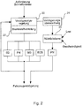
- Fig. 2 shows the schematic system structure of a device for controlling or regulating a brake system for performing rapid braking using several brake systems.
- the control or regulating device has a signal input for reading in a rapid braking request.
- a deceleration control 20 and a braking force distribution 22 cooperate to control the various in Fig. 2 shown brake systems (pneumatic brake PN, electrodynamic brake ED, magnetic rail brake EG, Eddy Current Brake ECB).
- the braking system of the rail vehicle has either all of the in Fig. 2 brake systems shown, or part of these brake systems.
- Air brakes also known as pneumatic brakes (PN)
- PN pneumatic brakes
- rail vehicles in particular traction vehicles, also have magnetic rail brakes (MG) and electrodynamic brakes (ED) in electric and diesel-electric vehicles, or hydraulic or retarder brakes in diesel-hydraulic vehicles.
- Newer vehicles, especially high-speed traction vehicles are also equipped with so-called Eddy Current Brakes (ECB).
- the safety-relevant brake system is a pneumatic brake (PN).
- Pneumatic brakes are usually available in rail vehicles. They are simply constructed and meet the corresponding requirements with regard to the safety assessment. In particular, pneumatic brakes can be used to delay the vehicle to a standstill. When performing rapid braking, the pressure of the pneumatic brake (PN) can be controlled or regulated on the basis of the speed, the load, or both variables.
- This pressure control or regulation is possible on the one hand if the pneumatic brake only interacts with the other brake systems in order to carry out the rapid braking, but in particular also then, if the rapid braking is continued using only the pneumatic braking system as a safety-relevant braking system after the total braking force of the vehicle has been judged to be too low or too high.
- a maximum deceleration can be achieved during the rapid braking with the pneumatic brake by speed or load-dependent pressure control of the pneumatic brake.
- the braking force distribution 22 specifies what proportion of the braking torque is to be contributed by the respective braking system. For this, the execution according to Fig. 2 For example, the braking forces of the braking systems involved in rapid braking can be regulated. As a result, the total braking force can be divided between the individual braking systems. In particular, the lowest possible braking torque is applied to wearing brake systems, for example the pneumatic brake (PN), while wear-free brakes, such as the electrodynamic brake (ED), provide the maximum possible braking torque.
- the deceleration control 20 initially specifies the required deceleration of the system and thus the required total braking force, which is then converted into braking torque requests for the individual systems by the braking force distribution 22.
- the vehicle decelerates due to the individual braking torques from the individual braking systems.
- the deceleration of the vehicle is measured and observed in the deceleration control 20.
- the deceleration monitor 24 checks whether the deceleration achieved is sufficiently high to meet the requirements for rapid braking or whether the deceleration achieved is too low or too high. If the latter is the case, a fall-back level 26 is activated, by means of which the further brake systems are deactivated and the braking is carried out exclusively by the pneumatic brake PN.
- the pneumatic brake is activated in the fallback level 26 in the in Fig. 2 shown device depending on the current load and the current speed of the vehicle.
Claims (14)
- Procédé de commande ou de régulation d'une installation de frein, notamment d'une installation de frein d'un véhicule ferroviaire, l'installation de frein ayant au moins un système (PN) de frein pertinent du point de vue de la sécurité et au moins un autre système (ED, MG, ECB) de frein,
caractérisé par les stades suivants :on lit une demande (S10) de frein rapide,on effectue un freinage rapide en utilisant au moins l'un des autres systèmes (S20) de frein,on surveille la force de frein d'ensemble du véhicule (S16),on contrôle si la force de frein d'ensemble est inférieure ou est supérieure à une valeur de seuil (S18),si l'on est inférieur ou supérieur à la valeur de seuil, on continue à effectuer le freinage rapide en utilisant exclusivement le système (S20) de frein pertinent du point de vue de la sécurité. - Procédé suivant la revendication 1,
dans lequel la surveillance de la force de frein d'ensemble du véhicule (S16) a lieu par mesure d'une décélération d'ensemble dans le sens de la marche. - Procédé suivant la revendication 2,
dans lequel la mesure de la décélération d'ensemble dans le sens de la marche s'effectue par un capteur d'accélération. - Procédé suivant l'une des revendications précédentes,
dans lequel le système de frein pertinent du point de vue de la sécurité est un frein (PN) pneumatique. - Procédé suivant la revendication 4,
dans lequel on commande ou on règle la pression du frein (PN) pneumatique à l'aide de la vitesse et/ou de la charge. - Procédé suivant l'une des revendications précédentes,
dans lequel l'autre système de frein est un frein (ED) électrodynamique, un frein (MG) électromagnétique sur rail ou un frein (ECB) à courant de Foucault. - Procédé suivant l'une des revendications précédentes,
dans lequel on effectue une régulation de la force de frein des systèmes (PN, ED, MG, ECB) de frein participant au freinage rapide. - Dispositif de commande ou de régulation d'une installation de frein, notamment d'une installation de frein d'un véhicule ferroviaire, l'installation de frein ayant au moins un système (PN) de frein pertinent du point de vue de la sécurité et au moins un autre système (ED, MG, ECB) de frein,
caractérisé en ce que le dispositif comporte :une entrée de signal pour lire une demande de frein rapide,un dispositif (20, 22) pour effectuer un freinage rapide en utilisant plusieurs systèmes (ED, MG, ECB, PN) de frein,un dispositif (24) de surveillance de la force de frein d'ensemble du véhicule,un dispositif (24) de contrôle de la force de frein d'ensemble sur le point de savoir si elle est inférieure ou supérieure à une valeur de seuil, etun dispositif (26) pour effectuer le freinage rapide en utilisant exclusivement le système (PN) de frein pertinent du point de vue de la sécurité. - Dispositif suivant la revendication 8,
dans lequel le dispositif (24) de surveillance de la force de frein d'ensemble du véhicule est conformé pour mesurer une décélération du véhicule dans le sens de la marche et le dispositif (24) de surveillance de la force de frein d'ensemble du véhicule a un capteur d'accélération. - Dispositif suivant la revendication 8 ou 9,
dans lequel le système de frein pertinent du point de vue de la sécurité est un frein (PN) pneumatique. - Dispositif suivant l'une des revendications 8 à 10,
dans lequel l'autre système de frein est un frein (ED) électrodynamique, un frein (MG) électromagnétique sur rail ou un frein (ECB) à courant de Foucault. - Dispositif suivant l'une des revendications 8 à 1,
dans lequel le dispositif a un dispositif (22) de répartition de la force de frein entre les systèmes (ED, MG, ECB, PN) de frein participant au freinage rapide. - Installation de frein ayant un dispositif de commande ou de régulation suivant l'une des revendications 8 à 12.
- Véhicule ferroviaire ayant un dispositif de commande ou de régulation suivant l'une des revendications 8 à 12 ou une installation de frein suivant la revendication 13.
Applications Claiming Priority (2)
| Application Number | Priority Date | Filing Date | Title |
|---|---|---|---|
| DE102016108998.2A DE102016108998A1 (de) | 2016-05-17 | 2016-05-17 | Verfahren und Vorrichtung zur Steuerung oder Regelung einer Bremsanlage |
| PCT/EP2017/061317 WO2017198535A1 (fr) | 2016-05-17 | 2017-05-11 | Procédé et dispositif pour commander ou réguler un dispositif de freinage |
Publications (3)
| Publication Number | Publication Date |
|---|---|
| EP3458323A1 EP3458323A1 (fr) | 2019-03-27 |
| EP3458323B1 true EP3458323B1 (fr) | 2020-03-25 |
| EP3458323B2 EP3458323B2 (fr) | 2023-05-10 |
Family
ID=58709938
Family Applications (1)
| Application Number | Title | Priority Date | Filing Date |
|---|---|---|---|
| EP17723976.1A Active EP3458323B2 (fr) | 2016-05-17 | 2017-05-11 | Procédé et dispositif pour commander ou réguler un dispositif de freinage |
Country Status (4)
| Country | Link |
|---|---|
| EP (1) | EP3458323B2 (fr) |
| CN (1) | CN109153380B (fr) |
| DE (1) | DE102016108998A1 (fr) |
| WO (1) | WO2017198535A1 (fr) |
Families Citing this family (4)
| Publication number | Priority date | Publication date | Assignee | Title |
|---|---|---|---|---|
| DE102017106119A1 (de) | 2017-03-22 | 2018-09-27 | Knorr-Bremse Systeme für Schienenfahrzeuge GmbH | Bremsvorrichtung für Schienenfahrzeuge und Verfahren zum Bremsen von Schienenfahrzeugen |
| DE102018251776A1 (de) * | 2018-12-28 | 2020-07-02 | Siemens Mobility GmbH | Fahrzeug |
| CN110059433B (zh) * | 2019-04-26 | 2023-05-16 | 南京辑星科技有限公司 | 一种直线型涡流磁制动系统的磁组布局高效耦合设计方法 |
| DE102019129328A1 (de) * | 2019-10-30 | 2021-05-06 | Knorr-Bremse Systeme für Schienenfahrzeuge GmbH | Verfahren zur Schnellbremsung eines Schienenfahrzeugs mit definierten Bremsvorgaben |
Citations (8)
| Publication number | Priority date | Publication date | Assignee | Title |
|---|---|---|---|---|
| DE6608396U (de) | 1965-04-15 | 1971-08-05 | Siemens Ag | Bremseinrichtung fuer schienenfahrzeuge. |
| DE10135797A1 (de) | 2001-07-23 | 2003-02-13 | Knorr Bremse Systeme | Bremssteuervorrichtung für Schienenfahrzeuge, die mit einer elektrischen Bremse und einer pneumatischen Bremse ausgestattet sind |
| WO2007096213A1 (fr) | 2006-02-23 | 2007-08-30 | Siemens Aktiengesellschaft | Procédé pour freiner un véhicule ferroviaire |
| WO2011050950A1 (fr) | 2009-10-28 | 2011-05-05 | Knorr-Bremse Systeme für Schienenfahrzeuge GmbH | Dispositif de freinage de secours d'un véhicule sur rails |
| WO2012126946A2 (fr) | 2011-03-23 | 2012-09-27 | Siemens Aktiengesellschaft | Actionneur pour un système de freinage d'un véhicule ferroviaire |
| DE102011052545A1 (de) | 2011-08-10 | 2013-02-14 | Bombardier Transportation Gmbh | Bremssteuerung für ein Fahrzeug |
| DE102012202118A1 (de) | 2012-02-13 | 2013-08-14 | Siemens Aktiengesellschaft | Bremseinrichtung eines Fahrzeugs |
| WO2015132232A1 (fr) | 2014-03-05 | 2015-09-11 | Knorr-Bremse Systeme für Schienenfahrzeuge GmbH | Procédé servant à commander un système de freinage d'un véhicule sur rails |
Family Cites Families (5)
| Publication number | Priority date | Publication date | Assignee | Title |
|---|---|---|---|---|
| DE10301947B4 (de) * | 2003-01-20 | 2009-04-16 | Siemens Ag | Verfahren zum Bremsen einer Lokomotive und Bremsvorrichtung für eine Lokomotive |
| DE102006043892A1 (de) * | 2006-09-19 | 2008-03-27 | Siemens Ag | Verfahren und Einrichtung zum Bremsen eines Schienenfahrzeuges |
| JP5761348B2 (ja) * | 2011-07-19 | 2015-08-12 | トヨタ自動車株式会社 | ブレーキ制御装置 |
| CN104936815B (zh) * | 2012-11-21 | 2017-08-11 | 庞巴迪运输有限公司 | 用于轨道交通工具轮轴的制动操作方法和用于轨道交通工具的制动系统 |
| CN104786850B (zh) * | 2015-02-13 | 2017-06-27 | 郑州宇通客车股份有限公司 | 一种复合制动系统、及其制动控制系统和制动控制方法 |
-
2016
- 2016-05-17 DE DE102016108998.2A patent/DE102016108998A1/de not_active Ceased
-
2017
- 2017-05-11 CN CN201780030288.9A patent/CN109153380B/zh active Active
- 2017-05-11 WO PCT/EP2017/061317 patent/WO2017198535A1/fr unknown
- 2017-05-11 EP EP17723976.1A patent/EP3458323B2/fr active Active
Patent Citations (8)
| Publication number | Priority date | Publication date | Assignee | Title |
|---|---|---|---|---|
| DE6608396U (de) | 1965-04-15 | 1971-08-05 | Siemens Ag | Bremseinrichtung fuer schienenfahrzeuge. |
| DE10135797A1 (de) | 2001-07-23 | 2003-02-13 | Knorr Bremse Systeme | Bremssteuervorrichtung für Schienenfahrzeuge, die mit einer elektrischen Bremse und einer pneumatischen Bremse ausgestattet sind |
| WO2007096213A1 (fr) | 2006-02-23 | 2007-08-30 | Siemens Aktiengesellschaft | Procédé pour freiner un véhicule ferroviaire |
| WO2011050950A1 (fr) | 2009-10-28 | 2011-05-05 | Knorr-Bremse Systeme für Schienenfahrzeuge GmbH | Dispositif de freinage de secours d'un véhicule sur rails |
| WO2012126946A2 (fr) | 2011-03-23 | 2012-09-27 | Siemens Aktiengesellschaft | Actionneur pour un système de freinage d'un véhicule ferroviaire |
| DE102011052545A1 (de) | 2011-08-10 | 2013-02-14 | Bombardier Transportation Gmbh | Bremssteuerung für ein Fahrzeug |
| DE102012202118A1 (de) | 2012-02-13 | 2013-08-14 | Siemens Aktiengesellschaft | Bremseinrichtung eines Fahrzeugs |
| WO2015132232A1 (fr) | 2014-03-05 | 2015-09-11 | Knorr-Bremse Systeme für Schienenfahrzeuge GmbH | Procédé servant à commander un système de freinage d'un véhicule sur rails |
Also Published As
| Publication number | Publication date |
|---|---|
| EP3458323B2 (fr) | 2023-05-10 |
| WO2017198535A1 (fr) | 2017-11-23 |
| CN109153380B (zh) | 2021-03-23 |
| EP3458323A1 (fr) | 2019-03-27 |
| CN109153380A (zh) | 2019-01-04 |
| DE102016108998A1 (de) | 2017-11-23 |
Similar Documents
| Publication | Publication Date | Title |
|---|---|---|
| EP3458323B1 (fr) | Procédé et dispositif pour commander ou réguler un dispositif de freinage | |
| EP2688779B1 (fr) | Actionneur pour un système de freinage d'un véhicule ferroviaire | |
| EP2648949B1 (fr) | Procédé de commande d'un système de frein à friction régulé antipatinage d'un véhicule ferroviaire | |
| EP2741945B1 (fr) | Système de freinage comportant un dispositif de frein électromagnétique sur rail | |
| EP2825430B1 (fr) | Procédé de commande d'un système d'entraînement et de freinage d'un véhicule, comportant un frein à friction | |
| EP3802244B1 (fr) | Unité de contrôle et méthode pour contrôler un actionneur de frein d'un véhicule, notamment d'un véhicule ferroviaire | |
| EP3113993B1 (fr) | Procédé servant à commander un système de freinage d'un véhicule sur rails | |
| EP3448728B1 (fr) | Dispositif et procédé pour optimiser l'utilisation de l'adhérence entre la roue et le rail | |
| DE102005016001A1 (de) | Abbremsen eines Fahrzeugs im Rahmen eines Nothalts | |
| EP1289811B1 (fr) | Procede et dispositif pour surveiller l'efficacite des systemes de freinage de vehicules | |
| DE102021104799A1 (de) | Verfahren und Vorrichtung zur Überwachung und Beeinflussung des thermischen Zustands eines Reibungsbremssystems eines Schienenfahrzeugs | |
| DE102021104800A1 (de) | Verfahren zur Bestimmung einer optimalen oder maximal zulässigen Geschwindigkeit eines Schienenfahrzeugs | |
| DE102013219438A1 (de) | Bremsaktor für ein Bremssystem eines Fahrzeugs sowie Verfahren zum Abbremsen eines Fahrzeugs | |
| DE102011113120B4 (de) | Bremssteuereinrichtung für eine Bremsanlage eines Schienenfahrzeugs, Bremsanlage, Schienenfahrzeug sowie Verfahren zum Steuern einer Bremsanlage | |
| EP3419872B1 (fr) | Procédé et dispositif pour commander ou réguler un dispositif de freinage | |
| DE102016218905A1 (de) | Verfahren und Vorrichtung zum Steuern einer Bremsanlage für ein Fahrzeug, Bremsanlage und Fahrzeug | |
| EP3600946B1 (fr) | Dispositif de freinage pour véhicules ferroviaires et procédé de freinage de véhicules ferroviaires | |
| DE102017108034A1 (de) | Verfahren und Vorrichtung zum automatischen Feststellen einer Beladungsänderung eines Kraftfahrzeugs und Kraftfahrzeug | |
| EP0569697A1 (fr) | Procédé pour contrôle de surcharge d'un frein d'un remorque d'un convoi routier | |
| EP3038868B1 (fr) | Procédé pour freiner une véhicule de chémin de fer et système de commande et/ou réglage pour un système de freinage | |
| EP3197734A1 (fr) | Procédé de commande d'un système de freinage et système de freinage | |
| DD270820A3 (de) | Verfahren zur regelung der bremsintensitaet an schienenfahrzeugen | |
| DE102013013381A1 (de) | Verfahren zum Betrieb einer Bremsvorrichtung eines Fahrzeugs | |
| EP3600945B1 (fr) | Dispositif de freinage pour véhicules ferroviaires et procédé de freinage de véhicules ferroviaires | |
| WO2024056521A1 (fr) | Procédé de commande d'un véhicule, programme informatique et/ou support lisible par ordinateur, dispositif de commande et véhicule, en particulier véhicule utilitaire |
Legal Events
| Date | Code | Title | Description |
|---|---|---|---|
| STAA | Information on the status of an ep patent application or granted ep patent |
Free format text: STATUS: UNKNOWN |
|
| STAA | Information on the status of an ep patent application or granted ep patent |
Free format text: STATUS: THE INTERNATIONAL PUBLICATION HAS BEEN MADE |
|
| PUAI | Public reference made under article 153(3) epc to a published international application that has entered the european phase |
Free format text: ORIGINAL CODE: 0009012 |
|
| STAA | Information on the status of an ep patent application or granted ep patent |
Free format text: STATUS: REQUEST FOR EXAMINATION WAS MADE |
|
| 17P | Request for examination filed |
Effective date: 20181217 |
|
| AK | Designated contracting states |
Kind code of ref document: A1 Designated state(s): AL AT BE BG CH CY CZ DE DK EE ES FI FR GB GR HR HU IE IS IT LI LT LU LV MC MK MT NL NO PL PT RO RS SE SI SK SM TR |
|
| AX | Request for extension of the european patent |
Extension state: BA ME |
|
| DAV | Request for validation of the european patent (deleted) | ||
| DAX | Request for extension of the european patent (deleted) | ||
| GRAP | Despatch of communication of intention to grant a patent |
Free format text: ORIGINAL CODE: EPIDOSNIGR1 |
|
| STAA | Information on the status of an ep patent application or granted ep patent |
Free format text: STATUS: GRANT OF PATENT IS INTENDED |
|
| INTG | Intention to grant announced |
Effective date: 20191010 |
|
| GRAS | Grant fee paid |
Free format text: ORIGINAL CODE: EPIDOSNIGR3 |
|
| GRAA | (expected) grant |
Free format text: ORIGINAL CODE: 0009210 |
|
| STAA | Information on the status of an ep patent application or granted ep patent |
Free format text: STATUS: THE PATENT HAS BEEN GRANTED |
|
| AK | Designated contracting states |
Kind code of ref document: B1 Designated state(s): AL AT BE BG CH CY CZ DE DK EE ES FI FR GB GR HR HU IE IS IT LI LT LU LV MC MK MT NL NO PL PT RO RS SE SI SK SM TR |
|
| REG | Reference to a national code |
Ref country code: GB Ref legal event code: FG4D Free format text: NOT ENGLISH |
|
| REG | Reference to a national code |
Ref country code: DE Ref legal event code: R096 Ref document number: 502017004390 Country of ref document: DE |
|
| REG | Reference to a national code |
Ref country code: AT Ref legal event code: REF Ref document number: 1248235 Country of ref document: AT Kind code of ref document: T Effective date: 20200415 Ref country code: IE Ref legal event code: FG4D Free format text: LANGUAGE OF EP DOCUMENT: GERMAN |
|
| PG25 | Lapsed in a contracting state [announced via postgrant information from national office to epo] |
Ref country code: RS Free format text: LAPSE BECAUSE OF FAILURE TO SUBMIT A TRANSLATION OF THE DESCRIPTION OR TO PAY THE FEE WITHIN THE PRESCRIBED TIME-LIMIT Effective date: 20200325 Ref country code: FI Free format text: LAPSE BECAUSE OF FAILURE TO SUBMIT A TRANSLATION OF THE DESCRIPTION OR TO PAY THE FEE WITHIN THE PRESCRIBED TIME-LIMIT Effective date: 20200325 Ref country code: NO Free format text: LAPSE BECAUSE OF FAILURE TO SUBMIT A TRANSLATION OF THE DESCRIPTION OR TO PAY THE FEE WITHIN THE PRESCRIBED TIME-LIMIT Effective date: 20200625 |
|
| PG25 | Lapsed in a contracting state [announced via postgrant information from national office to epo] |
Ref country code: BG Free format text: LAPSE BECAUSE OF FAILURE TO SUBMIT A TRANSLATION OF THE DESCRIPTION OR TO PAY THE FEE WITHIN THE PRESCRIBED TIME-LIMIT Effective date: 20200625 Ref country code: LV Free format text: LAPSE BECAUSE OF FAILURE TO SUBMIT A TRANSLATION OF THE DESCRIPTION OR TO PAY THE FEE WITHIN THE PRESCRIBED TIME-LIMIT Effective date: 20200325 Ref country code: SE Free format text: LAPSE BECAUSE OF FAILURE TO SUBMIT A TRANSLATION OF THE DESCRIPTION OR TO PAY THE FEE WITHIN THE PRESCRIBED TIME-LIMIT Effective date: 20200325 Ref country code: HR Free format text: LAPSE BECAUSE OF FAILURE TO SUBMIT A TRANSLATION OF THE DESCRIPTION OR TO PAY THE FEE WITHIN THE PRESCRIBED TIME-LIMIT Effective date: 20200325 Ref country code: GR Free format text: LAPSE BECAUSE OF FAILURE TO SUBMIT A TRANSLATION OF THE DESCRIPTION OR TO PAY THE FEE WITHIN THE PRESCRIBED TIME-LIMIT Effective date: 20200626 |
|
| REG | Reference to a national code |
Ref country code: NL Ref legal event code: MP Effective date: 20200325 |
|
| REG | Reference to a national code |
Ref country code: LT Ref legal event code: MG4D |
|
| PG25 | Lapsed in a contracting state [announced via postgrant information from national office to epo] |
Ref country code: NL Free format text: LAPSE BECAUSE OF FAILURE TO SUBMIT A TRANSLATION OF THE DESCRIPTION OR TO PAY THE FEE WITHIN THE PRESCRIBED TIME-LIMIT Effective date: 20200325 |
|
| PG25 | Lapsed in a contracting state [announced via postgrant information from national office to epo] |
Ref country code: PT Free format text: LAPSE BECAUSE OF FAILURE TO SUBMIT A TRANSLATION OF THE DESCRIPTION OR TO PAY THE FEE WITHIN THE PRESCRIBED TIME-LIMIT Effective date: 20200818 Ref country code: LT Free format text: LAPSE BECAUSE OF FAILURE TO SUBMIT A TRANSLATION OF THE DESCRIPTION OR TO PAY THE FEE WITHIN THE PRESCRIBED TIME-LIMIT Effective date: 20200325 Ref country code: SK Free format text: LAPSE BECAUSE OF FAILURE TO SUBMIT A TRANSLATION OF THE DESCRIPTION OR TO PAY THE FEE WITHIN THE PRESCRIBED TIME-LIMIT Effective date: 20200325 Ref country code: IS Free format text: LAPSE BECAUSE OF FAILURE TO SUBMIT A TRANSLATION OF THE DESCRIPTION OR TO PAY THE FEE WITHIN THE PRESCRIBED TIME-LIMIT Effective date: 20200725 Ref country code: CZ Free format text: LAPSE BECAUSE OF FAILURE TO SUBMIT A TRANSLATION OF THE DESCRIPTION OR TO PAY THE FEE WITHIN THE PRESCRIBED TIME-LIMIT Effective date: 20200325 Ref country code: RO Free format text: LAPSE BECAUSE OF FAILURE TO SUBMIT A TRANSLATION OF THE DESCRIPTION OR TO PAY THE FEE WITHIN THE PRESCRIBED TIME-LIMIT Effective date: 20200325 Ref country code: SM Free format text: LAPSE BECAUSE OF FAILURE TO SUBMIT A TRANSLATION OF THE DESCRIPTION OR TO PAY THE FEE WITHIN THE PRESCRIBED TIME-LIMIT Effective date: 20200325 Ref country code: EE Free format text: LAPSE BECAUSE OF FAILURE TO SUBMIT A TRANSLATION OF THE DESCRIPTION OR TO PAY THE FEE WITHIN THE PRESCRIBED TIME-LIMIT Effective date: 20200325 |
|
| REG | Reference to a national code |
Ref country code: DE Ref legal event code: R026 Ref document number: 502017004390 Country of ref document: DE |
|
| PLBI | Opposition filed |
Free format text: ORIGINAL CODE: 0009260 |
|
| PLAX | Notice of opposition and request to file observation + time limit sent |
Free format text: ORIGINAL CODE: EPIDOSNOBS2 |
|
| 26 | Opposition filed |
Opponent name: SIEMENS MOBILITY GMBH Effective date: 20201222 |
|
| PG25 | Lapsed in a contracting state [announced via postgrant information from national office to epo] |
Ref country code: LI Free format text: LAPSE BECAUSE OF NON-PAYMENT OF DUE FEES Effective date: 20200531 Ref country code: MC Free format text: LAPSE BECAUSE OF FAILURE TO SUBMIT A TRANSLATION OF THE DESCRIPTION OR TO PAY THE FEE WITHIN THE PRESCRIBED TIME-LIMIT Effective date: 20200325 Ref country code: DK Free format text: LAPSE BECAUSE OF FAILURE TO SUBMIT A TRANSLATION OF THE DESCRIPTION OR TO PAY THE FEE WITHIN THE PRESCRIBED TIME-LIMIT Effective date: 20200325 Ref country code: CH Free format text: LAPSE BECAUSE OF NON-PAYMENT OF DUE FEES Effective date: 20200531 Ref country code: ES Free format text: LAPSE BECAUSE OF FAILURE TO SUBMIT A TRANSLATION OF THE DESCRIPTION OR TO PAY THE FEE WITHIN THE PRESCRIBED TIME-LIMIT Effective date: 20200325 |
|
| PG25 | Lapsed in a contracting state [announced via postgrant information from national office to epo] |
Ref country code: PL Free format text: LAPSE BECAUSE OF FAILURE TO SUBMIT A TRANSLATION OF THE DESCRIPTION OR TO PAY THE FEE WITHIN THE PRESCRIBED TIME-LIMIT Effective date: 20200325 |
|
| REG | Reference to a national code |
Ref country code: BE Ref legal event code: MM Effective date: 20200531 |
|
| PG25 | Lapsed in a contracting state [announced via postgrant information from national office to epo] |
Ref country code: LU Free format text: LAPSE BECAUSE OF NON-PAYMENT OF DUE FEES Effective date: 20200511 |
|
| PG25 | Lapsed in a contracting state [announced via postgrant information from national office to epo] |
Ref country code: IE Free format text: LAPSE BECAUSE OF NON-PAYMENT OF DUE FEES Effective date: 20200511 |
|
| PG25 | Lapsed in a contracting state [announced via postgrant information from national office to epo] |
Ref country code: SI Free format text: LAPSE BECAUSE OF FAILURE TO SUBMIT A TRANSLATION OF THE DESCRIPTION OR TO PAY THE FEE WITHIN THE PRESCRIBED TIME-LIMIT Effective date: 20200325 Ref country code: BE Free format text: LAPSE BECAUSE OF NON-PAYMENT OF DUE FEES Effective date: 20200531 |
|
| PLBB | Reply of patent proprietor to notice(s) of opposition received |
Free format text: ORIGINAL CODE: EPIDOSNOBS3 |
|
| GBPC | Gb: european patent ceased through non-payment of renewal fee |
Effective date: 20210511 |
|
| PG25 | Lapsed in a contracting state [announced via postgrant information from national office to epo] |
Ref country code: GB Free format text: LAPSE BECAUSE OF NON-PAYMENT OF DUE FEES Effective date: 20210511 |
|
| PG25 | Lapsed in a contracting state [announced via postgrant information from national office to epo] |
Ref country code: TR Free format text: LAPSE BECAUSE OF FAILURE TO SUBMIT A TRANSLATION OF THE DESCRIPTION OR TO PAY THE FEE WITHIN THE PRESCRIBED TIME-LIMIT Effective date: 20200325 Ref country code: MT Free format text: LAPSE BECAUSE OF FAILURE TO SUBMIT A TRANSLATION OF THE DESCRIPTION OR TO PAY THE FEE WITHIN THE PRESCRIBED TIME-LIMIT Effective date: 20200325 Ref country code: CY Free format text: LAPSE BECAUSE OF FAILURE TO SUBMIT A TRANSLATION OF THE DESCRIPTION OR TO PAY THE FEE WITHIN THE PRESCRIBED TIME-LIMIT Effective date: 20200325 |
|
| PG25 | Lapsed in a contracting state [announced via postgrant information from national office to epo] |
Ref country code: MK Free format text: LAPSE BECAUSE OF FAILURE TO SUBMIT A TRANSLATION OF THE DESCRIPTION OR TO PAY THE FEE WITHIN THE PRESCRIBED TIME-LIMIT Effective date: 20200325 Ref country code: AL Free format text: LAPSE BECAUSE OF FAILURE TO SUBMIT A TRANSLATION OF THE DESCRIPTION OR TO PAY THE FEE WITHIN THE PRESCRIBED TIME-LIMIT Effective date: 20200325 |
|
| PUAH | Patent maintained in amended form |
Free format text: ORIGINAL CODE: 0009272 |
|
| STAA | Information on the status of an ep patent application or granted ep patent |
Free format text: STATUS: PATENT MAINTAINED AS AMENDED |
|
| 27A | Patent maintained in amended form |
Effective date: 20230510 |
|
| AK | Designated contracting states |
Kind code of ref document: B2 Designated state(s): AL AT BE BG CH CY CZ DE DK EE ES FI FR GB GR HR HU IE IS IT LI LT LU LV MC MK MT NL NO PL PT RO RS SE SI SK SM TR |
|
| REG | Reference to a national code |
Ref country code: DE Ref legal event code: R102 Ref document number: 502017004390 Country of ref document: DE |
|
| P01 | Opt-out of the competence of the unified patent court (upc) registered |
Effective date: 20230528 |
|
| REG | Reference to a national code |
Ref country code: AT Ref legal event code: MM01 Ref document number: 1248235 Country of ref document: AT Kind code of ref document: T Effective date: 20220511 |
|
| PG25 | Lapsed in a contracting state [announced via postgrant information from national office to epo] |
Ref country code: AT Free format text: LAPSE BECAUSE OF NON-PAYMENT OF DUE FEES Effective date: 20220511 |
|
| PGFP | Annual fee paid to national office [announced via postgrant information from national office to epo] |
Ref country code: IT Payment date: 20230531 Year of fee payment: 7 Ref country code: FR Payment date: 20230517 Year of fee payment: 7 Ref country code: DE Payment date: 20230519 Year of fee payment: 7 |