EP3457768B1 - Pilot frequency transmission method for uplink shared channel, and related device - Google Patents
Pilot frequency transmission method for uplink shared channel, and related device Download PDFInfo
- Publication number
- EP3457768B1 EP3457768B1 EP17795614.1A EP17795614A EP3457768B1 EP 3457768 B1 EP3457768 B1 EP 3457768B1 EP 17795614 A EP17795614 A EP 17795614A EP 3457768 B1 EP3457768 B1 EP 3457768B1
- Authority
- EP
- European Patent Office
- Prior art keywords
- pilots
- shared channel
- uplink shared
- pilot
- comb
- Prior art date
- Legal status (The legal status is an assumption and is not a legal conclusion. Google has not performed a legal analysis and makes no representation as to the accuracy of the status listed.)
- Active
Links
- 230000005540 biological transmission Effects 0.000 title claims description 38
- 238000000034 method Methods 0.000 title claims description 31
- 230000011664 signaling Effects 0.000 claims description 44
- 238000012545 processing Methods 0.000 claims description 26
- 238000013507 mapping Methods 0.000 description 121
- 238000010586 diagram Methods 0.000 description 21
- 230000015654 memory Effects 0.000 description 14
- 239000000243 solution Substances 0.000 description 11
- 238000004891 communication Methods 0.000 description 7
- 238000004590 computer program Methods 0.000 description 7
- 230000006870 function Effects 0.000 description 4
- 230000008901 benefit Effects 0.000 description 3
- 230000007774 longterm Effects 0.000 description 3
- 230000008569 process Effects 0.000 description 3
- 238000010295 mobile communication Methods 0.000 description 2
- 238000012986 modification Methods 0.000 description 2
- 230000004048 modification Effects 0.000 description 2
- 238000004904 shortening Methods 0.000 description 2
- 239000000969 carrier Substances 0.000 description 1
- 230000001413 cellular effect Effects 0.000 description 1
- 125000004122 cyclic group Chemical group 0.000 description 1
- 238000013461 design Methods 0.000 description 1
- 238000004519 manufacturing process Methods 0.000 description 1
- 230000003287 optical effect Effects 0.000 description 1
- 230000002093 peripheral effect Effects 0.000 description 1
- 230000009467 reduction Effects 0.000 description 1
- 238000003860 storage Methods 0.000 description 1
- 239000012224 working solution Substances 0.000 description 1
Images


Classifications
-
- H—ELECTRICITY
- H04—ELECTRIC COMMUNICATION TECHNIQUE
- H04W—WIRELESS COMMUNICATION NETWORKS
- H04W52/00—Power management, e.g. TPC [Transmission Power Control], power saving or power classes
- H04W52/04—TPC
- H04W52/06—TPC algorithms
- H04W52/14—Separate analysis of uplink or downlink
- H04W52/146—Uplink power control
-
- H—ELECTRICITY
- H04—ELECTRIC COMMUNICATION TECHNIQUE
- H04W—WIRELESS COMMUNICATION NETWORKS
- H04W52/00—Power management, e.g. TPC [Transmission Power Control], power saving or power classes
- H04W52/04—TPC
- H04W52/06—TPC algorithms
- H04W52/16—Deriving transmission power values from another channel
-
- H—ELECTRICITY
- H04—ELECTRIC COMMUNICATION TECHNIQUE
- H04L—TRANSMISSION OF DIGITAL INFORMATION, e.g. TELEGRAPHIC COMMUNICATION
- H04L27/00—Modulated-carrier systems
- H04L27/26—Systems using multi-frequency codes
- H04L27/2601—Multicarrier modulation systems
- H04L27/2602—Signal structure
- H04L27/261—Details of reference signals
- H04L27/2613—Structure of the reference signals
-
- H—ELECTRICITY
- H04—ELECTRIC COMMUNICATION TECHNIQUE
- H04L—TRANSMISSION OF DIGITAL INFORMATION, e.g. TELEGRAPHIC COMMUNICATION
- H04L5/00—Arrangements affording multiple use of the transmission path
- H04L5/0001—Arrangements for dividing the transmission path
- H04L5/0003—Two-dimensional division
- H04L5/0005—Time-frequency
-
- H—ELECTRICITY
- H04—ELECTRIC COMMUNICATION TECHNIQUE
- H04L—TRANSMISSION OF DIGITAL INFORMATION, e.g. TELEGRAPHIC COMMUNICATION
- H04L5/00—Arrangements affording multiple use of the transmission path
- H04L5/003—Arrangements for allocating sub-channels of the transmission path
- H04L5/0044—Arrangements for allocating sub-channels of the transmission path allocation of payload
-
- H—ELECTRICITY
- H04—ELECTRIC COMMUNICATION TECHNIQUE
- H04L—TRANSMISSION OF DIGITAL INFORMATION, e.g. TELEGRAPHIC COMMUNICATION
- H04L5/00—Arrangements affording multiple use of the transmission path
- H04L5/003—Arrangements for allocating sub-channels of the transmission path
- H04L5/0048—Allocation of pilot signals, i.e. of signals known to the receiver
- H04L5/0051—Allocation of pilot signals, i.e. of signals known to the receiver of dedicated pilots, i.e. pilots destined for a single user or terminal
-
- H—ELECTRICITY
- H04—ELECTRIC COMMUNICATION TECHNIQUE
- H04L—TRANSMISSION OF DIGITAL INFORMATION, e.g. TELEGRAPHIC COMMUNICATION
- H04L5/00—Arrangements affording multiple use of the transmission path
- H04L5/003—Arrangements for allocating sub-channels of the transmission path
- H04L5/0078—Timing of allocation
- H04L5/0082—Timing of allocation at predetermined intervals
-
- H—ELECTRICITY
- H04—ELECTRIC COMMUNICATION TECHNIQUE
- H04W—WIRELESS COMMUNICATION NETWORKS
- H04W52/00—Power management, e.g. TPC [Transmission Power Control], power saving or power classes
- H04W52/04—TPC
- H04W52/30—TPC using constraints in the total amount of available transmission power
- H04W52/32—TPC of broadcast or control channels
- H04W52/325—Power control of control or pilot channels
-
- H—ELECTRICITY
- H04—ELECTRIC COMMUNICATION TECHNIQUE
- H04W—WIRELESS COMMUNICATION NETWORKS
- H04W72/00—Local resource management
- H04W72/04—Wireless resource allocation
- H04W72/044—Wireless resource allocation based on the type of the allocated resource
- H04W72/0473—Wireless resource allocation based on the type of the allocated resource the resource being transmission power
-
- H—ELECTRICITY
- H04—ELECTRIC COMMUNICATION TECHNIQUE
- H04W—WIRELESS COMMUNICATION NETWORKS
- H04W80/00—Wireless network protocols or protocol adaptations to wireless operation
- H04W80/08—Upper layer protocols
-
- H—ELECTRICITY
- H04—ELECTRIC COMMUNICATION TECHNIQUE
- H04W—WIRELESS COMMUNICATION NETWORKS
- H04W88/00—Devices specially adapted for wireless communication networks, e.g. terminals, base stations or access point devices
- H04W88/02—Terminal devices
-
- H—ELECTRICITY
- H04—ELECTRIC COMMUNICATION TECHNIQUE
- H04W—WIRELESS COMMUNICATION NETWORKS
- H04W88/00—Devices specially adapted for wireless communication networks, e.g. terminals, base stations or access point devices
- H04W88/08—Access point devices
Definitions
- the present invention relates to the field of communications, and particularly to a method and device for transmitting a pilot of an uplink shared channel.
- LTE Long Term Evolution
- the Frame Structure Type 1 (FS1) is applicable to the existing LTE Frequency Division Duplex (FDD) system.
- FDD Frequency Division Duplex
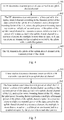
- Fig.1 illustrates a schematic structural diagram of the FS1, where a radio frame with the length of 10ms over each carrier includes ten 1ms sub-frames, and each sub-frame includes two slots with the length of 0.5ms.
- a Transmission Time Interval (TTI) for transmitting uplink and downlink data is 1ms.
- the Frame Structure Type 2 (FS2) is applicable to the existing LTE Time Division Duplex (TDD) system.
- TDD Time Division Duplex
- Fig.2 illustrates a schematic structural diagram of the FS2.
- each radio frame with the length of 10ms includes two half-frames with the length of 5ms, and each half-frame includes five sub-frames with the length of 1ms.
- the sub-frames in the FS2 are categorized into downlink sub-frames, uplink sub-frames, and special sub-frames, where each special sub-frame includes three components of a Downlink Pilot Time Slot (DwPTS), a Guard Period (GP), and an Uplink Pilot Time Slot (UpPTS), where a downlink pilot, downlink traffic data, and downlink control signaling can be transmitted in the DwPTS; no signal is transmitted in the GP; and only a random access signal and a Sounding Reference Symbol (SRS) can be transmitted, but neither uplink traffic data nor uplink control information can be transmitted, in the UpPTS.
- Each half-frame includes at least one downlink sub-frame, at least one uplink sub-frame, and at most one special sub-frame.
- Table 1 depicts seven uplink-downlink sub-frame configurations supported in the FS2.
- Uplink-downlink configurations Uplink-downlink configuration Downlink-to-Uplink Switch-point periodicity Sub-frame number 0 1 2 3 4 5 6 7 8 9 0 5 ms D S U U U D S U U U 1 5 ms D S U U D D S U U D 2 5 ms D S U D D D S U D D 3 10 ms D S U U U D D D D D D 4 10 ms D S U U D D D D D D D 5 10 ms D S U D D D D D D D D D 6 5 ms D S U U U U D S U U D
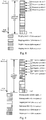
- Fig.3a and Fig.3b illustrate structural diagrams of data and pilots (i.e., reference signals, or Demodulation Reference Signals (DMRS's) for demodulating the data), of an LTE Physical Uplink Shared Channel (PUSCH) in a sub-frame.
- data and pilots i.e., reference signals, or Demodulation Reference Signals (DMRS's) for demodulating the data
- PUSCH Physical Uplink Shared Channel
- CP Cyclic Prefix
- the pilots are transmitted in the fourth symbol in each slot of each sub-frame, and the data are transmitted in the other symbols than the fourth symbol.
- Fig.3b with an extended CP, the pilots are transmitted in the third symbol in each slot of each sub-frame, and the data are transmitted in the other symbols than the third symbol.
- An uplink pilot is a UE-specific pilot generated according to the size of a real bandwidth scheduled by the PUSCH. Transmit power of a DMRS is the same as transmit power of data.
- MU-MIMO uplink Multi User-Multi Input Multi Output
- the same pilot-based sequence can be shifted cyclically using each column of pilots to orthogonally transmit pilots of a plurality of UEs sharing the same resource, so that a receiver can distinguish pilot information of the different UEs from each other by shifting the pilot information cyclically.
- One of working solutions to shortening a delay is to reduce the length of a TTI.
- the existing channel transmission is generally defined in a sub-frame, and when a PUSCH is transmitted in a shorter TTI than 1ms, the DMRS structure designed for a 1ms sub-frame in the LTE system can be reused, and DMRS's of short data transmission in a sub-frame can be transmitted at the same time position, where the short data transmission is defined as data transmission with a smaller length of time than 1ms.
- pilot sequences of the respective short data transmission can be transmitted in the same resource region in a frequency division multiplexing mode with a comb-like pattern so that uplink data can be transmitted and demodulated correctly.
- a plurality of UEs can share the DMRS resources, but there has been absent a definite solution to determining transmit power of a DMRS.
- the method comprises transmitting an indication for new-type reference signals to a user equipment, the new-type reference signals have a reduced density of reference signals in frequency domain, and resource elements not used by reference signals in symbols for the new-type reference signals are used for coverage enhancement; receiving the new-type reference signals; and performing channel estimation based on the new-type reference signals.
- WO 2013/067345 provides a method for communication in a wireless telecommunication system.
- the method comprises transmitting, by a UE, a DMRS, wherein REs carrying the DMRS are separated into a plurality of portions, each of the portions occupying a different OFDM symbol in a single slot of a radio subframe.
- a new PUSCH DMRS format may provide accurate channel estimates, increased RS density in the time domain at the expense of relaxed PAPR, and/or a symmetric pattern to ease the channel estimation algorithm.
- the PUSCH DMRS format may provide sufficient RS density in the time domain to enable accurate channel estimation for high Doppler scenarios.
- Embodiments of the invention provide a method and device for transmitting a pilot of an uplink shared channel so as to determine transmit power of a pilot when pilot sequences of respective short data transmission are transmitted in the same resource region in a frequency division multiplexing mode with a comb-like pattern.
- an embodiment of the invention provides a method for transmitting pilots of an uplink shared channel.
- AUE determines transmit power of data carried in an uplink shared channel.
- the UE determines transmit power of the pilots carried in the uplink shared channel according to the transmit power of the data carried in the uplink shared channel, and a pilot power boosting factor of the UE.
- the pilot power boosting factor represents a multiple of transmit power of the pilots of the uplink shared channel in a resource element relative to transmit power of the data carried in the uplink shared channel in a resource element, the multiple is more than 1, and the pilots are transmitted in a symbol occupied by the pilots with a comb-like pattern.
- the UE transmits the pilots of the uplink shared channel at the transmit power of the pilots.
- the pilot power boosting factor of the UE is determined according to the number of different pilot sequences transmitted concurrently in the same symbol with frequency division multiplexing, where a largest value of the pilot power boosting factor is in proportion to the number of pilot sequences multiplexed in the same symbol with the comb-like pattern; or the pilot power boosting factor of the UE is determined according to the number of UEs for which multiplex pilots are in the same symbol with the comb-like pattern; where the number of UEs is an integer greater than 1; wherein a largest value of the pilot power boosting factor is in proportion to the number of UEs for which multiplex pilots are in the same symbol with the comb-like pattern.
- the number of pilot sequences transmitted in the same symbol with frequency division multiplexing or the number of UEs for which multiplex pilots are in the same symbol with the comb-like pattern is configured by the network side to the UE via higher-layer signaling, or predefined between the network side and the UE in a protocol.
- a Transmission Time Interval (TTI) of the uplink shared channel is less than 1 millisecond
- an embodiment of the invention provides a method for transmitting pilots of an uplink shared channel.
- a base station determines transmit power at which a UE transmits data carried in an uplink shared channel.
- the base station determines transmit power at which the UE transmits the pilots of the uplink shared channel according to the transmit power of the data carried in the uplink shared channel of the UE, and a pilot power boosting factor of the UE.
- the pilot power boosting factor represents a multiple of transmit power of the pilots of the uplink shared channel in a resource element relative to transmit power of the data carried in the uplink shared channel in a resource element, the multiple is more than 1, and the pilots are transmitted in a symbol occupied by the pilots with a comb-like pattern.
- the pilot power boosting factor of the UE is determined according to the number of different pilot sequences transmitted concurrently in the same symbol with frequency division multiplexing, where a largest value of the pilot power boosting factor is in proportion to the number of pilot sequences multiplexed in the same symbol with the comb-like pattern; or the pilot power boosting factor of the UE is determined according to the number of UEs for which multiplex pilots are in the same symbol with the comb-like pattern; where the number of UEs is an integer greater than 1; wherein a largest value of the pilot power boosting factor is in proportion to the number of UEs for which multiplex pilots are in the same symbol with the comb-like pattern.
- the number of pilot sequences transmitted in the same symbol with frequency division multiplexing or the number of UEs for which multiplex pilots are in the same symbol with the comb-like pattern is configured by the network side to the UE via higher-layer signaling, or predefined between the network side and the UE in a protocol.
- a Transmission Time Interval (TTI) of the uplink shared channel is less than 1 millisecond
- an embodiment of the invention provides a UE.
- the UE includes a first processing module, a second processing module and a transmitting module.
- the first processing module is configured to determine transmit power of data carried in an uplink shared channel.
- the second processing module is configured to determine transmit power of pilots carried in the uplink shared channel according to the transmit power of the data carried in the uplink shared channel, and a pilot power boosting factor of the UE.
- the pilot power boosting factor represents a multiple of transmit power of the pilots of the uplink shared channel in a resource element relative to transmit power of the data carried in the uplink shared channel in a resource element, the multiple is more than 1, and the pilots are transmitted in a symbol occupied by the pilots with a comb-like pattern.
- the transmitting module is configured to transmit the pilots of the uplink shared channel at the transmit power of the pilots.
- the pilot power boosting factor of the UE is determined according to the number of different pilot sequences transmitted concurrently in the same symbol with frequency division multiplexing, where a largest value of the pilot power boosting factor is in proportion to the number of pilot sequences multiplexed in the same symbol with the comb-like pattern; or the pilot power boosting factor of the UE is determined according to the number of UEs for which multiplex pilots are in the same symbol with the comb-like pattern; where the number of UEs is an integer greater than 1; wherein a largest value of the pilot power boosting factor is in proportion to the number of UEs for which multiplex pilots are in the same symbol with the comb-like pattern.
- the number of pilot sequences transmitted in the same symbol with frequency division multiplexing or the number of UEs for which multiplex pilots are in the same symbol with the comb-like pattern is configured by the network side to the UE via higher-layer signaling, or predefined between the network side and the UE in a protocol.
- a Transmission Time Interval (TTI) of the uplink shared channel is less than 1 millisecond.
- an embodiment of the invention provides a base station.
- the base station includes a first processing module and a second processing module.
- the first processing module is configured to determine transmit power at which a UE transmits data carried in an uplink shared channel.
- the second processing module is configured to determine transmit power at which the UE transmits pilots of the uplink shared channel according to the transmit power of the data carried in the uplink shared channel of the UE, and a pilot power boosting factor of the UE.
- the pilot power boosting factor represents a multiple of transmit power of the pilots of the uplink shared channel in a resource element relative to transmit power of the data of the uplink shared channel in a resource element, the multiple is more than 1, and the pilots are transmitted in a symbol occupied by the pilots with a comb-like pattern.
- the pilot power boosting factor of the UE is determined according to the number of different pilot sequences transmitted concurrently in the same symbol with frequency division multiplexing, where a largest value of the pilot power boosting factor is in proportion to the number of pilot sequences multiplexed in the same symbol with the comb-like pattern; or the pilot power boosting factor of the UE is determined according to the number of UEs for which multiplex pilots are in the same symbol with the comb-like pattern; wherein the number of UEs is an integer greater than 1; wherein a largest value of the pilot power boosting factor is in proportion to the number of UEs for which multiplex pilots are in the same symbol with the comb-like pattern.
- the number of pilot sequences transmitted in the same symbol with frequency division multiplexing or the number of UEs for which multiplex pilots are in the same symbol with the comb-like pattern is configured by the network side to the UE via higher-layer signaling, or predefined between the network side and the UE in a protocol.
- a Transmission Time Interval (TTI) of the uplink shared channel is less than 1 millisecond
- the UE determines the transmit power of the pilots carried in the uplink shared channel according to the transmit power of the data carried in the uplink shared channel, and the pilot power boosting factor of the UE.
- the pilot power boosting factor of the UE is defined as a multiple of transmit power of the pilots of the uplink shared channel in a resource element relative to transmit power of the data carried in the uplink shared channel in a resource element, and the multiple is defined to be more than or equal to 1, so that there is provided a solution to determine transmit power of pilots in the case that pilot sequences of respective short data transmission are transmitted in the same resource region in a frequency division multiplexing mode with a comb-like pattern, and the accuracy of channel estimation can be improved by boosting the transmit power of the pilots while lowering the transmission density of the pilots.
- GSM Global System of Mobile communication
- CDMA Code Division Multiple Access
- WCDMA Wideband Code Division Multiple Access
- GPRS General Packet Radio Service
- LTE Long Term Evolution
- LTE-A Advanced Long Term Evolution
- UMTS Universal Mobile Telecommunication System
- a User Equipment includes but will not be limited to a Mobile Station (MS), a mobile terminal, a mobile telephone, a handset, a portable equipment, etc., and the user equipment can communicate with one or more core networks over a Radio Access Network (RAN).
- the user equipment can be a mobile phone (referred to as a "cellular" phone), a computer with a function of radio communication, etc., and the user equipment can also be a portable, pocket, handheld, built-in-computer, or on-vehicle mobile device.
- a base station e.g., an access point
- the base station can be such a device in an access network that communicates with a radio terminal over one or more sectors via an air interface.
- the base station can be configured to convert a received air frame into an IP packet, and a received IP packet into an air frame, and operate as a router between the radio terminal, and the remaining components of the access network, where the remaining components of the access network can include an Internet Protocol (IP) network.
- IP Internet Protocol
- the base station can further coordinate attribute management on the air interface, and for example, the base station can be a Base Communication module Station (BTS) in a GSM or CDMA system, or can be a base station (Node B) in a WCDMA system, or can be an evolved base station (Node B or eNB or e-Node B) in an LTE system, although the invention will not be limited thereto.
- BTS Base Communication module Station
- Node B base station
- eNB evolved base station
- e-Node B evolved base station
- DMRS's of short data transmission and particularly short data transmission with a smaller length than 0.5ms are transmitted in only a column of pilot positions in a sub-frame
- the density of the DMRS's of short data transmission in the time domain will be lower than that of 1ms data transmission, so the performance of interpolation in the time domain may be affected, and also the interference robustness may be degraded as compared with DMRS's transmitted in two columns, so that the performance of channel estimation for the short data transmission may be degraded.
- DMRS's of short data transmission are transmitted over only a part of frequency resources in a Single Carrier-Frequency Division Multiple Access (SC-FDMA) symbol in which the DMRS's are transmitted, so as long as total transmit power of a DMRS SC-FDMA symbol of a UE does not exceed total transmit power of a data SC-FDMA symbol, transmit power of a DMRS may be boosted to some extent to thereby improve the performance of channel estimation and the interference robustness for the short data transmission.
- Embodiments of the invention propose a DMRS power boosting solution while the DMRS's are transmitted with a comb-like pattern, to thereby improve the performance of channel estimation.
- the comb-like pattern refers to that pilots are transmitted according to a start frequency position, and a frequency mapping interval or a frequency mapping density or a pilot reusage factor.
- a core idea of the invention lies in that when DMRS's are transmitted with a comb-like pattern, DMRS's of a UE are transmitted in only a part of Resource Elements (REs) in an SC-FDMA symbol. Accordingly as long as total transmit power of a DMRS SC-FDMA symbol does not exceed total transmit power of a data SC-FDMA symbol, power of a DMRS in each RE may be boosted. Since the density of DMRS's is lowered, the performance of channel estimation can be improved due to the boosted power of the DMRS in each RE.
- REs Resource Elements
- a detailed flow of a method for transmitting pilots of an uplink shared channel at the UE side is as follows.
- a UE determines transmit power of data carried in an uplink shared channel.
- a transmission time interval of the uplink shared channel is less than 1 millisecond.
- the transmit power of the data carried in the uplink shared channel can be notified by a base station to the UE, or can be predefined between a base station and the UE in a protocol.
- the UE determines transmit power of the pilots carried in the uplink shared channel according to the transmit power of the data carried in the uplink shared channel, and a pilot power boosting factor of the UE, where the pilot power boosting factor represents a multiple of transmit power of the pilots of the uplink shared channel in a resource element relative to transmit power of the data carried in the uplink shared channel in a resource element, the multiple is more than or equal to 1, and the pilots are transmitted in a symbol occupied by the pilots with a comb-like pattern.
- the sum of the transmit power of the pilots of the uplink shared channel in resource elements for transmitting the pilots in the symbol occupied by the pilots is no more than the transmit power of the data of the uplink shared channel.
- the pilot power boosting factor of the UE can be obtained in the following several implementations without any limitation thereto.
- the pilot power boosting factor of the UE is configured by the network side to the UE via higher-layer signaling.
- pilot power boosting factor is configured via the higher-layer signaling; or a plurality of pilot power boosting factors are configured via the higher-layer signaling, where each pilot power boosting factor corresponds to a frequency mapping interval or a frequency mapping density at which the pilots are transmitted with the comb-like pattern, or the number of UEs for which multiplex pilots are in the same symbol with the comb-like pattern.
- K pilot power boosting factors are prescribed in a system, and represented as ⁇ n1, n2, ..., nk ⁇ , the UE is notified of one of the K pilot power boosting factors via ⁇ log 2 K ⁇ bits of higher-layer signaling, and the UE calculates the transmit power of the pilot of the uplink shared channel in an RE from the transmit power of the data of the uplink shared channel in an RE according to the received pilot power boosting factor.
- one of the prescribed K pilot power boosting factors represents no power boosting.
- the pilot power boosting factor of the UE is predefined between the network side and the UE in a protocol.
- the network side and the UE predefine one pilot power boosting factor in the protocol.
- one pilot power boosting factor is predefined, that is, the pilot power boosting factor is applicable in any case.
- pilot power boosting factors each is predefined for respective frequency mapping intervals or respective frequency mapping densities at which the pilots are transmitted with the comb-like pattern, or respective numbers of UEs for which multiplex pilots are in the same symbol with the comb-like pattern.
- the pilot power boosting factor is n1.
- n1 is no more than 2 (linear power is boosted by a factor of 2, and the same will apply hereinafter) or 3dB (power in dB is boosted by a factor of 3, and the same will apply hereinafter).
- the pilot power boosting factor is n2.
- n2 is no more than 3 or 4.77dB.
- the pilot power boosting factor is n3.
- n3 is no more than 4 or 6dB.
- the pilot power boosting factor is n4.
- n4 is no more than 6 or 7.78dB.
- the UE determines the pilot power boosting factor according to a frequency mapping interval at which the pilots are transmitted with the comb-like pattern.
- the UE determines the pilot power boosting factor according to a frequency mapping density at which the pilots are transmitted with the comb-like pattern.
- the UE determines the pilot power boosting factor according to the number of UEs for which multiplex pilots are in the same symbol with the comb-like pattern.
- the UE determines that the frequency mapping interval or the frequency mapping density at which the pilots are transmitted with the comb-like pattern, or the number of UEs for which multiplex pilots are in the same symbol with the comb-like pattern is 2, then the UE will determine the pilot power boosting factor as 2 or 3dB. If the UE determines that the frequency mapping interval or the frequency mapping density at which the pilots are transmitted with the comb-like pattern, or the number of UEs for which multiplex pilots are in the same symbol with the comb-like pattern is 3, then the UE will determine the pilot power boosting factor as 3 or 4.77dB.
- the UE determines that the frequency mapping interval or the frequency mapping density at which the pilots are transmitted with the comb-like pattern, or the number of UEs for which multiplex pilots are in the same symbol with the comb-like pattern is 4, then the UE will determine the pilot power boosting factor as 4 or 6dB. If the UE determines that the frequency mapping interval or the frequency mapping density at which the pilots are transmitted with the comb-like pattern, or the number of UEs for which multiplex pilots are in the same symbol with the comb-like pattern is 6, then the UE will determine the pilot power boosting factor as 6 or 7.78dB.
- the largest value of the pilot power boosting factor is in proportion to the frequency mapping interval or the frequency mapping density at which the pilots are transmitted with the comb-like pattern, or the number of UEs for which multiplex pilots are in the same symbol with the comb-like pattern.
- the frequency mapping interval or the frequency mapping density at which the pilots are transmitted with the comb-like pattern, or the number of UEs for which multiplex pilots are in the same symbol with the comb-like pattern is configured by the network side to the UE via higher-layer signaling, or predefined between the network side and the UE in a protocol.
- pilot reusage factor is defined as the number of different pilot sequences transmitted concurrently in the same symbol in a frequency division multiplexing mode.
- the UE transmits the pilot of the uplink shared channel at the transmit power of the pilot.
- the UE transmits the pilot of the uplink shared channel at the transmit power of the pilot of the uplink shared channel determined in the step 402.
- a base station determines transmit power at which a UE transmits data carried in an uplink shared channel.
- a transmission time interval of the uplink shared channel is less than 1 millisecond.
- the base station determines transmit power at which the UE transmits pilots of the uplink shared channel according to the transmit power of the data carried in the uplink shared channel of the UE, and a pilot power boosting factor of the UE, where the pilot power boosting factor represents a multiple of transmit power of the pilots of the uplink shared channel in a resource element relative to transmit power of the data carried in the uplink shared channel in a resource element, the multiple is more than or equal to 1, and the pilots are transmitted in a symbol occupied by the pilots with a comb-like pattern.
- the sum of the transmit power of the pilots of the uplink shared channel in resource elements for transmitting the pilots in the symbol occupied by the pilots is no more than the transmit power of the data of the uplink shared channel.
- the pilot power boosting factor of the UE is configured by the network side to the UE via higher-layer signaling, or predefined between the network side and the UE in a protocol, or determined according to a frequency mapping interval or a frequency mapping density at which the pilots are transmitted with the comb-like pattern, or the number of UEs for which multiplex pilots are in the same symbol with the comb-like pattern.
- pilot power boosting factor is configured via the higher-layer signaling; or a plurality of pilot power boosting factors are configured via the higher-layer signaling, where each pilot power boosting factor corresponds to a frequency mapping interval or a frequency mapping density at which the pilots are transmitted with the comb-like pattern, or the number of UEs for which multiplex pilots are in the same symbol with the comb-like pattern.
- pilot power boosting factor of the UE is predefined between the network side and the UE in the protocol
- one pilot power boosting factor can be predefined; or pilot power boosting factors each can be predefined for respective frequency mapping intervals or frequency mapping densities at which the pilots are transmitted with the comb-like pattern, or the numbers of UEs for which multiplex pilots are in the same symbol with the comb-like pattern.
- the largest value of the pilot power boosting factor is in proportion to the frequency mapping interval or the frequency mapping density at which the pilots are transmitted with the comb-like pattern, or the number of UEs for which multiplex pilots are in the same symbol with the comb-like pattern.
- the frequency mapping interval or the frequency mapping density at which the pilots are transmitted with the comb-like pattern, or the number of UEs for which multiplex pilots are in the same symbol with the comb-like pattern is configured by the network side to the UE via higher-layer signaling, or predefined between the network side and the UE in a protocol.
- a process of transmitting pilots of an uplink shared channel will be described below in details in a particular embodiment thereof.
- Fig.6 to Fig.8 illustrates comb-like mapping patterns respectively when the frequency mapping interval or the frequency mapping density, or the number of UEs for which multiplex pilots are in the same symbol with the comb-like pattern is 2, 3, 4, and 6 respectively, where the pilots are mapped in an elementary frequency unit, for example, but the same mapping pattern will apply to each of a plurality of elementary frequency units; and for example, an elementary frequency unit includes 12 consecutive sub-carriers in the frequency domain, but the same description will apply to the other sizes of an elementary frequency unit, and the other pilot mapping patterns.
- Power of the pilots of the uplink shared channel can be boosted as follows in some particular embodiments.
- pilot power boosting factor is configured via higher-layer signaling.
- the frequency mapping interval or the frequency mapping density of the pilots, or the number of UEs for which multiplex pilots are in the same symbol with the comb-like pattern, in the system is prescribed as 4, there are three DMRS REs of a UE in an elementary frequency unit, and the highest total power of a pilot SC-FDMA symbol is the same as power of a data SC-FDMA symbol, so power of the pilot in an SC-FDMA symbol can be boosted by at most 6dB.
- power of PUSCH data transmitted in an RE is defined as E Data _ RE .
- the pilot power boosting factor can alternatively be defined directly as a multiple of transmit power of a DMRS transmitted in an RE relative to transmit power of data transmitted in an RE
- a set of pilot power boosting factors n can be defined as ⁇ 1, 2, 3, 4 ⁇
- pilot power boosting factor is predefined.
- the frequency mapping interval or the frequency mapping density of the pilots, or the number of UEs for which multiplex pilots are in the same symbol with the comb-like pattern, in the system is prescribed as 4, there are three DMRS REs of a UE in an elementary frequency unit, and the highest total power of a pilot SC-FDMA symbol is the same as power of a data SC-FDMA symbol, so power of the pilot in the SC-FDMA symbol can be boosted by at most 6dB.
- pilot power boosting factors corresponding respectively to different frequency mapping intervals are predefined, and power of PUSCH data transmitted in an RE is defined as E Data_RE .
- a uniform pilot power boosting factor is predefined for all of the frequency mapping intervals or the frequency mapping densities of the pilots, or the numbers of UEs for which multiplex pilots are in the same symbol with the comb-like pattern.
- the lowest frequency mapping interval or frequency mapping density of the pilots, or the lowest number of UEs for which multiplex pilots are in the same symbol with the comb-like pattern is 2
- the highest total power of a pilot SC-FDMA symbol is the same as power of a data SC-FDMA symbol
- E Data_RE .
- the pilot power boosting factor is determined according to the frequency mapping interval or the frequency mapping density of the pilots, or the pilot reusage factor.
- the pilot power boosting factor is the number of UEs for which multiplex pilots are in the same symbol with the comb-like pattern.
- the frequency mapping interval or the frequency mapping density of the pilots, or the number of UEs for which multiplex pilots are in the same symbol with the comb-like pattern in the system is prescribed as M, then there will be 12/M REs for transmitting an DMRS in an elementary frequency unit.
- Power of the pilot in an SC-FDMA RE can be boosted by at most 10log 10 M dB, and Table 2 can be created according to the largest available power boosting, where Table 2 depicts a mapping relationship between the frequency mapping interval or the frequency mapping density of the pilots, or the number of UEs for which multiplex pilots are in the same symbol with the comb-like pattern, and the pilot power boosting factor.
- Table 2 Frequency mapping interval or frequency mapping density or pilot reusage factor 2 3 4 6 Pilot power 3 4.77 6 7.78 boosting factor n (dB)
- power of PUSCH data transmitted in an RE is defined as E Data_RE
- Table 3 Frequency mapping interval or frequency mapping density or pilot reusage factor 2 3 4 6 Pilot power boosting factor n (multiply) 2 3 4 6
- the UE generally includes a first processing module 1001, a second processing module 1002 and a transmitting module 1003.
- the first processing module 1001 is configured to determine transmit power of data carried in an uplink shared channel.
- the second processing module 1002 is configured to determine transmit power of pilots carried in the uplink shared channel according to the transmit power of the data carried in the uplink shared channel, and a pilot power boosting factor of the UE, where the pilot power boosting factor represents a multiple of transmit power of the pilots of the uplink shared channel in a resource element relative to transmit power of the data carried in the uplink shared channel in a resource element, the multiple is more than or equal to 1, and the pilots are transmitted in a symbol occupied by the pilots with a comb-like pattern.
- the transmitting module 1003 is configured to transmit the pilots of the uplink shared channel at the transmit power of the pilots.
- the sum of the transmit power of the pilots of the uplink shared channel in resource elements for transmitting the pilots in the symbol occupied by the pilots is no more than the transmit power of the data of the uplink shared channel.
- the pilot power boosting factor of the UE is configured by the network side to the UE via higher-layer signaling, or predefined between the network side and the UE in a protocol, or determined according to a frequency mapping interval or a frequency mapping density at which the pilots are transmitted with the comb-like pattern, or the number of UEs for which multiplex pilots are in the same symbol with the comb-like pattern.
- pilot power boosting factor of the UE is configured by the network side to the UE via the higher-layer signaling:
- pilot power boosting factor is configured via the higher-layer signaling; or a plurality of pilot power boosting factors are configured via the higher-layer signaling, where each pilot power boosting factor corresponds to a frequency mapping interval or a frequency mapping density at which the pilots are transmitted with the comb-like pattern, or the number of UEs for which multiplex pilots are in the same symbol with the comb-like pattern.
- pilot power boosting factor of the UE is predefined between the network side and the UE in the protocol:
- One pilot power boosting factor is predefined, or pilot power boosting factors each is predefined for respective frequency mapping intervals or frequency mapping densities at which the pilots are transmitted with the comb-like pattern, or numbers of UEs for which multiplex pilots are in the same symbol with the comb-like pattern.
- the largest value of the pilot power boosting factor is in proportion to the frequency mapping interval or the frequency mapping density at which the pilots are transmitted with the comb-like pattern, or the number of UEs for which multiplex pilots are in the same symbol with the comb-like pattern.
- the frequency mapping interval or the frequency mapping density at which the pilots are transmitted with the comb-like pattern, or the number of UEs for which multiplex pilots are in the same symbol with the comb-like pattern is configured by the network side to the UE via higher-layer signaling, or predefined between the network side and the UE in a protocol.
- a Transmission Time Interval (TTI) of the uplink shared channel is less than 1 millisecond.
- the base station generally includes a first processing module 1101 and a second processing module 1102.
- the first processing module 1101 is configured to determine transmit power at which a UE transmits data carried in an uplink shared channel.
- the second processing module 1102 is configured to determine transmit power at which the UE transmits pilots of the uplink shared channel according to the transmit power of the data carried in the uplink shared channel of the UE, and a pilot power boosting factor of the UE, where the pilot power boosting factor represents a multiple of transmit power of the pilots of the uplink shared channel in a resource element relative to transmit power of the data carried in the uplink shared channel in a resource element, the multiple is more than or equal to 1, and the pilots are transmitted in a symbol occupied by the pilots with a comb-like pattern.
- the sum of the transmit power of the pilots of the uplink shared channel in resource elements for transmitting the pilots in the symbol occupied by the pilots is no more than the transmit power of the data of the uplink shared channel.
- the pilot power boosting factor of the UE is configured by the network side to the UE via higher-layer signaling, or predefined between the network side and the UE in a protocol, or determined according to a frequency mapping interval or a frequency mapping density at which the pilots are transmitted with the comb-like pattern, or the number of UEs for which multiplex pilots are in the same symbol with the comb-like pattern.
- pilot power boosting factor of the UE is configured by the network side to the UE via the higher-layer signaling:
- One pilot power boosting factor is configured via the higher-layer signaling; or a plurality of pilot power boosting factors are configured via the higher-layer signaling, where each pilot power boosting factor corresponds to a frequency mapping interval or a frequency mapping density at which the pilots are transmitted with the comb-like pattern, or the number of UEs for which multiplex pilots are in the same symbol with the comb-like pattern.
- pilot power boosting factor of the UE is predefined between the network side and the UE in the protocol:
- One pilot power boosting factor is predefined, or a plurality of pilot power boosting factors each is predefined for respective frequency mapping intervals or frequency mapping densities at which the pilots are transmitted with the comb-like pattern, or numbers of UEs for which multiplex pilots are in the same symbol with the comb-like pattern.
- the largest value of the pilot power boosting factor is in proportion to the frequency mapping interval or the frequency mapping density at which the pilots are transmitted with the comb-like pattern, or the number of UEs for which multiplex pilots are in the same symbol with the comb-like pattern.
- the frequency mapping interval or the frequency mapping density at which the pilots are transmitted with the comb-like pattern, or the number of UEs for which multiplex pilots are in the same symbol with the comb-like pattern is configured by the network side to the UE via higher-layer signaling, or predefined between the network side and the UE in a protocol.
- a Transmission Time Interval (TTI) of the uplink shared channel is less than 1 millisecond.
- the UE generally includes a processor 1201, a memory 1202, and a transceiver 1203, where the transceiver 1203 is configured to transmit and receive data under the control of the processor 1201, preset program is stored in the memory 1202, and the processor 1201 is configured to read the program in the memory 1202, and to execute the program.
- the program is executed to determine transmit power of data carried in an uplink shared channel.
- the program is executed to determine transmit power of pilots carried in the uplink shared channel according to the transmit power of the data carried in the uplink shared channel, and a pilot power boosting factor of the UE, where the pilot power boosting factor represents a multiple of transmit power of the pilots of the uplink shared channel in a resource element relative to transmit power of the data carried in the uplink shared channel in a resource element, the multiple is more than or equal to 1, and the pilots are transmitted in a symbol occupied by the pilots with a comb-like pattern.
- the program is executed to transmit the pilots of the uplink shared channel at the transmit power of the pilots through the transceiver 1203.
- the sum of the transmit power of the pilots of the uplink shared channel in resource elements for transmitting the pilots in the symbol occupied by the pilots is no more than the transmit power of the data of the uplink shared channel.
- the pilot power boosting factor of the UE is configured by the network side to the UE via higher-layer signaling, or predefined between the network side and the UE in a protocol, or determined according to a frequency mapping interval or a frequency mapping density at which the pilots are transmitted with the comb-like pattern, or the number of UEs for which multiplex pilots are in the same symbol with the comb-like pattern.
- pilot power boosting factor of the UE is configured by the network side to the UE via the higher-layer signaling:
- One pilot power boosting factor is configured via the higher-layer signaling; or a plurality of pilot power boosting factors are configured via the higher-layer signaling, where each pilot power boosting factor corresponds to a frequency mapping interval or a frequency mapping density at which the pilots are transmitted with the comb-like pattern, or the number of UEs for which multiplex pilots are in the same symbol with the comb-like pattern.
- pilot power boosting factor of the UE is predefined between the network side and the UE in the protocol:
- One pilot power boosting factor is predefined, or a plurality pilot power boosting factors each is predefined for respective frequency mapping intervals or frequency mapping densities at which the pilots are transmitted with the comb-like pattern, or numbers of UEs for which multiplex pilots are in the same symbol with the comb-like pattern.
- the largest value of the pilot power boosting factor is in proportion to the frequency mapping interval or the frequency mapping density at which the pilots are transmitted with the comb-like pattern, or the number of UEs for which multiplex pilots are in the same symbol with the comb-like pattern.
- the frequency mapping interval or the frequency mapping density at which the pilots are transmitted with the comb-like pattern, or the number of UEs for which multiplex pilots are in the same symbol with the comb-like pattern is configured by the network side to the UE via higher-layer signaling, or predefined between the network side and the UE in a protocol.
- a Transmission Time Interval (TTI) of the uplink shared channel is less than 1 millisecond.
- the base station generally includes a processor 1301, a memory 1302, and a transceiver 1303, where the transceiver 1303 is configured to transmit and receive data under the control of the processor 1301, preset program is stored in the memory 1302, and the processor 1301 is configured to read the program in the memory 1302, and to execute the program.
- the program is executed to determine transmit power at which a UE transmits data carried in an uplink shared channel.
- the program is executed to determine transmit power at which the UE transmits pilots of the uplink shared channel according to the transmit power of the data carried in the uplink shared channel of the UE, and a pilot power boosting factor of the UE, where the pilot power boosting factor represents a multiple of transmit power of the pilots of the uplink shared channel in a resource element relative to transmit power of the data carried in the uplink shared channel in a resource element, the multiple is more than or equal to 1, and the pilots are transmitted in a symbol occupied by the pilots with a comb-like pattern.
- the sum of the transmit power of the pilots of the uplink shared channel in resource elements for transmitting the pilots in the symbol occupied by the pilots is no more than the transmit power of the data of the uplink shared channel.
- the pilot power boosting factor of the UE is configured by the network side to the UE via higher-layer signaling, or predefined between the network side and the UE in a protocol, or determined according to a frequency mapping interval or a frequency mapping density at which the pilots are transmitted with the comb-like pattern, or the number of UEs for which multiplex pilots are in the same symbol with the comb-like pattern.
- pilot power boosting factor of the UE is configured by the network side to the UE via the higher-layer signaling:
- One pilot power boosting factor is configured via the higher-layer signaling; or a plurality of pilot power boosting factors are configured via the higher-layer signaling, where each pilot power boosting factor corresponds to a frequency mapping interval or a frequency mapping density at which the pilots are transmitted with the comb-like pattern, or the number of UEs for which multiplex pilots are in the same symbol with the comb-like pattern.
- pilot power boosting factor of the UE is predefined between the network side and the UE in the protocol:
- One pilot power boosting factor is predefined, or pilot power boosting factors each is predefined for respective frequency mapping intervals or frequency mapping densities at which the pilots are transmitted with the comb-like pattern, or numbers of UEs for which multiplex pilots are in the same symbol with the comb-like pattern.
- the largest value of the pilot power boosting factor is in proportion to the frequency mapping interval or the frequency mapping density at which the pilots are transmitted with the comb-like pattern, or the number of UEs for which multiplex pilots are in the same symbol with the comb-like pattern.
- the frequency mapping interval or the frequency mapping density at which the pilots are transmitted with the comb-like pattern, or the number of UEs for which multiplex pilots are in the same symbol with the comb-like pattern is configured by the network side to the UE via higher-layer signaling, or predefined between the network side and the UE in a protocol.
- a Transmission Time Interval (TTI) of the uplink shared channel is less than 1 millisecond.
- the processor, the memory, and the transceiver are connected with each other over a bus
- the bus architecture can include any number of interconnecting buses and bridges to particularly link together various circuits including one or more processors represented by the processor, and one or more memories represented by the memory.
- the bus architecture can further link together various other circuits, e.g., a peripheral device, a manostat, a power management circuit, etc., all of which are well known in the art, so a further description thereof will be omitted in this context.
- a bus interface serves as an interface.
- the transceiver can be an element, or a number of elements, e.g., a receiver and a transmitter, which are units for communication with various other devices over a transmission medium.
- the processor is responsible for managing the bus architecture and performing normal processes, and the memory can be configured to store data for use by the processor in performing the operations.
- the UE determines the transmit power of the pilots carried in the uplink shared channel according to the transmit power of the data carried in the uplink shared channel, and the pilot power boosting factor of the UE, where the pilot power boosting factor of the UE is defined as a multiple of transmit power of the pilots of the uplink shared channel in a resource element relative to transmit power of the data carried in the uplink shared channel in a resource element, and the multiple is defined to be more than or equal to 1, so that there is provided a solution to determining transmit power of pilots in the case that pilot sequences of respective short data transmissions are transmitted in the same resource region in a frequency division multiplexing mode with a comb-like pattern, and the accuracy of channel estimation can be improved by boosting the transmit power of the pilots while lowering the transmission density of the pilots.
- the embodiments of the invention can be embodied as a method, a system or a computer program product. Therefore the invention can be embodied in the form of an all-hardware embodiment, an all-software embodiment or an embodiment of software and hardware in combination. Furthermore the invention can be embodied in the form of a computer program product embodied in one or more computer useable storage mediums (including but not limited to a disk memory, a CD-ROM, an optical memory, etc.) in which computer useable program codes are contained.
- a computer useable storage mediums including but not limited to a disk memory, a CD-ROM, an optical memory, etc.
- These computer program instructions can also be stored into a computer readable memory capable of directing the computer or the other programmable data processing device to operate in a specific manner so that the instructions stored in the computer readable memory create an article of manufacture including instruction means which perform the functions specified in the flow(s) of the flow chart and/or the block(s) of the block diagram.
- These computer program instructions can also be loaded onto the computer or the other programmable data processing device so that a series of operational steps are performed on the computer or the other programmable data processing device to create a computer implemented process so that the instructions executed on the computer or the other programmable device provide steps for performing the functions specified in the flow(s) of the flow chart and/or the block(s) of the block diagram.
Applications Claiming Priority (2)
| Application Number | Priority Date | Filing Date | Title |
|---|---|---|---|
| CN201610319785.8A CN107371225B (zh) | 2016-05-13 | 2016-05-13 | 一种上行共享信道的导频传输方法及相关设备 |
| PCT/CN2017/084132 WO2017193996A1 (zh) | 2016-05-13 | 2017-05-12 | 一种上行共享信道的导频传输方法及相关设备 |
Publications (3)
| Publication Number | Publication Date |
|---|---|
| EP3457768A1 EP3457768A1 (en) | 2019-03-20 |
| EP3457768A4 EP3457768A4 (en) | 2019-04-24 |
| EP3457768B1 true EP3457768B1 (en) | 2021-09-15 |
Family
ID=60267487
Family Applications (1)
| Application Number | Title | Priority Date | Filing Date |
|---|---|---|---|
| EP17795614.1A Active EP3457768B1 (en) | 2016-05-13 | 2017-05-12 | Pilot frequency transmission method for uplink shared channel, and related device |
Country Status (6)
| Country | Link |
|---|---|
| US (1) | US10757662B2 (zh) |
| EP (1) | EP3457768B1 (zh) |
| JP (1) | JP6731498B2 (zh) |
| KR (1) | KR102198619B1 (zh) |
| CN (1) | CN107371225B (zh) |
| WO (1) | WO2017193996A1 (zh) |
Families Citing this family (9)
| Publication number | Priority date | Publication date | Assignee | Title |
|---|---|---|---|---|
| WO2018027887A1 (en) * | 2016-08-12 | 2018-02-15 | Qualcomm Incorporated | Signaling for interlaced fdm uplink dmrs |
| CN109151970B (zh) * | 2017-06-16 | 2023-10-20 | 华为技术有限公司 | 一种发送功率的确定方法、处理芯片及通信设备 |
| CN110266463B (zh) * | 2017-07-17 | 2021-09-07 | 华为技术有限公司 | 数据传输方法和终端设备 |
| CN111434155B (zh) * | 2017-11-17 | 2023-07-18 | 株式会社Ntt都科摩 | 用户设备、无线通信方法、基站以及系统 |
| JP2021515998A (ja) * | 2018-01-18 | 2021-06-24 | オッポ広東移動通信有限公司Guangdong Oppo Mobile Telecommunications Corp., Ltd. | 時間領域リソースの決定方法、装置及びコンピュータ記憶媒体 |
| CN111130728B (zh) * | 2018-10-31 | 2023-08-25 | 维沃移动通信有限公司 | 一种传输方法、终端及网络侧设备 |
| WO2022056849A1 (zh) * | 2020-09-18 | 2022-03-24 | 北京小米移动软件有限公司 | 发送dmrs的方法、装置、终端和介质 |
| KR20220059160A (ko) | 2020-11-02 | 2022-05-10 | 김학진 | 바닷물을 이용한 산소 발생 장치 |
| JP2023128438A (ja) * | 2022-03-03 | 2023-09-14 | Kddi株式会社 | 多数のアンテナによって構成されるcell-free massive MIMOシステムの通信効率を向上させる制御装置並びにその制御方法、処理装置並びにその処理方法、及びプログラム |
Family Cites Families (18)
| Publication number | Priority date | Publication date | Assignee | Title |
|---|---|---|---|---|
| US8135088B2 (en) * | 2005-03-07 | 2012-03-13 | Q1UALCOMM Incorporated | Pilot transmission and channel estimation for a communication system utilizing frequency division multiplexing |
| US8738056B2 (en) * | 2006-05-22 | 2014-05-27 | Qualcomm Incorporation | Signal acquisition in a wireless communication system |
| US8107987B2 (en) * | 2007-02-14 | 2012-01-31 | Qualcomm Incorporated | Apparatus and method for uplink power control of wireless communications |
| US8379581B2 (en) * | 2008-12-08 | 2013-02-19 | Sharp Kabushiki Kaisha | Systems and methods for uplink power control |
| US8750257B2 (en) * | 2009-10-12 | 2014-06-10 | Lg Electronics Inc. | Method and apparatus for providing downlink reference signal transmission power information in a wireless communication system that supports multiple antennas |
| US9137076B2 (en) * | 2009-10-30 | 2015-09-15 | Qualcomm Incorporated | Method and apparatus for mutiplexing reference signal and data in a wireless communication system |
| CN103037491B (zh) * | 2011-09-30 | 2015-08-19 | 华为技术有限公司 | 功率控制方法、基站及装置 |
| CN103096448B (zh) * | 2011-10-28 | 2016-08-24 | 华为技术有限公司 | 上行功率控制的方法、用户设备和接入点 |
| US9374724B2 (en) * | 2011-11-03 | 2016-06-21 | Telefonaktiebolaget Lm Ericsson (Publ) | Channel estimation using reference signals |
| US20130343477A9 (en) * | 2011-11-04 | 2013-12-26 | Research In Motion Limited | PUSCH Reference Signal Design for High Doppler Frequency |
| CN103166880A (zh) | 2011-12-15 | 2013-06-19 | 中国移动通信集团公司 | 上行解调导频的发送方法、接收方法、基站及移动中继 |
| CN103327594B (zh) * | 2012-03-22 | 2017-04-05 | 电信科学技术研究院 | 上行功率控制方法、设备及系统 |
| CN103369650B (zh) * | 2012-03-26 | 2017-02-08 | 电信科学技术研究院 | 一种上行功率控制方法及用户设备 |
| US9167537B2 (en) * | 2012-06-05 | 2015-10-20 | Qualcomm Incorporated | Methods and apparatus for DLTPC rejection in downlink windup mode |
| US8873136B2 (en) * | 2013-01-30 | 2014-10-28 | Coherent, Inc. | High-gain face-pumped slab-amplifier |
| US9055536B2 (en) * | 2013-03-01 | 2015-06-09 | Qualcomm Incorporated | Apparatus and method of ULTPC rejection threshold optimization in WCDMA for power control algorithm 2 |
| WO2014142577A2 (ko) * | 2013-03-13 | 2014-09-18 | 엘지전자 주식회사 | 제어 정보를 전송하는 방법 및 이를 위한 장치 |
| WO2015042810A1 (en) * | 2013-09-25 | 2015-04-02 | Nec(China)Co., Ltd. | Method and apparatus for uplink data transmission in a wireless communication system |
-
2016
- 2016-05-13 CN CN201610319785.8A patent/CN107371225B/zh active Active
-
2017
- 2017-05-12 KR KR1020187034825A patent/KR102198619B1/ko active IP Right Grant
- 2017-05-12 EP EP17795614.1A patent/EP3457768B1/en active Active
- 2017-05-12 US US16/301,437 patent/US10757662B2/en active Active
- 2017-05-12 WO PCT/CN2017/084132 patent/WO2017193996A1/zh unknown
- 2017-05-12 JP JP2018560020A patent/JP6731498B2/ja active Active
Also Published As
| Publication number | Publication date |
|---|---|
| EP3457768A1 (en) | 2019-03-20 |
| US10757662B2 (en) | 2020-08-25 |
| CN107371225B (zh) | 2020-01-07 |
| US20190306808A1 (en) | 2019-10-03 |
| EP3457768A4 (en) | 2019-04-24 |
| KR102198619B1 (ko) | 2021-01-05 |
| KR20190002650A (ko) | 2019-01-08 |
| CN107371225A (zh) | 2017-11-21 |
| WO2017193996A1 (zh) | 2017-11-16 |
| JP2019515602A (ja) | 2019-06-06 |
| JP6731498B2 (ja) | 2020-07-29 |
Similar Documents
| Publication | Publication Date | Title |
|---|---|---|
| EP3457768B1 (en) | Pilot frequency transmission method for uplink shared channel, and related device | |
| US20230239889A1 (en) | Uplink Subframe Shortening in Time-Division Duplex (TDD) Systems | |
| CN110383739B (zh) | 在无线通信系统中在终端和基站之间发送和接收物理上行链路控制信道的方法和装置 | |
| EP3796586A1 (en) | Configuration method and device and receiving method and device for positioning reference signal of nr system | |
| CN107347005B (zh) | 配置探测参考信号的方法和装置 | |
| EP3934356B1 (en) | Data transmission method, terminal device, and network device | |
| EP3461195B1 (en) | Method and device for transmitting data | |
| KR20190038329A (ko) | 통신 시스템에서 프리엠션의 지시 방법 | |
| JP2020504484A (ja) | 基準信号の伝送方法及び通信装置 | |
| KR20210003835A (ko) | 데이터 전송 방법 및 데이터 전송 장치 | |
| EP3648389A1 (en) | Communication method, network device, and relay device | |
| RU2756849C1 (ru) | Способ связи, сетевое устройство и оконечное устройство | |
| EP2836038A1 (en) | Pilot signal sending method and receiving method, user equipment, and base station | |
| KR20180095691A (ko) | 데이터 전송 방법 및 사용자 장비 | |
| KR102526417B1 (ko) | 무선 통신 방법, 단말 및 네트워크 기기 | |
| KR20140142696A (ko) | 데이터 전송 방법 및 장치 | |
| EP3667960B1 (en) | Signal sending method, corresponding network device, and corresponding computer-readable storage medium | |
| CN108631910B (zh) | 一种数据传输方法及装置 | |
| WO2016169479A1 (zh) | 一种数据传输方法及设备 | |
| CN113950136B (zh) | 用于功率控制的方法、网络设备、计算机存储介质 | |
| US11212795B2 (en) | Method and apparatus for indicating and determining slot structure | |
| EP3386257B1 (en) | Radio communication method and equipment | |
| CN107231222B (zh) | 一种反馈信息的传输方法和装置 | |
| CN108811106B (zh) | 一种调度传输方法和装置 | |
| KR20230073307A (ko) | 통신 방법 및 장치 |
Legal Events
| Date | Code | Title | Description |
|---|---|---|---|
| STAA | Information on the status of an ep patent application or granted ep patent |
Free format text: STATUS: THE INTERNATIONAL PUBLICATION HAS BEEN MADE |
|
| PUAI | Public reference made under article 153(3) epc to a published international application that has entered the european phase |
Free format text: ORIGINAL CODE: 0009012 |
|
| STAA | Information on the status of an ep patent application or granted ep patent |
Free format text: STATUS: REQUEST FOR EXAMINATION WAS MADE |
|
| 17P | Request for examination filed |
Effective date: 20181126 |
|
| AK | Designated contracting states |
Kind code of ref document: A1 Designated state(s): AL AT BE BG CH CY CZ DE DK EE ES FI FR GB GR HR HU IE IS IT LI LT LU LV MC MK MT NL NO PL PT RO RS SE SI SK SM TR |
|
| AX | Request for extension of the european patent |
Extension state: BA ME |
|
| A4 | Supplementary search report drawn up and despatched |
Effective date: 20190326 |
|
| RIC1 | Information provided on ipc code assigned before grant |
Ipc: H04W 52/16 20090101ALI20190320BHEP Ipc: H04W 52/14 20090101AFI20190320BHEP Ipc: H04W 52/32 20090101ALI20190320BHEP |
|
| DAV | Request for validation of the european patent (deleted) | ||
| DAX | Request for extension of the european patent (deleted) | ||
| STAA | Information on the status of an ep patent application or granted ep patent |
Free format text: STATUS: EXAMINATION IS IN PROGRESS |
|
| 17Q | First examination report despatched |
Effective date: 20191022 |
|
| STAA | Information on the status of an ep patent application or granted ep patent |
Free format text: STATUS: EXAMINATION IS IN PROGRESS |
|
| GRAP | Despatch of communication of intention to grant a patent |
Free format text: ORIGINAL CODE: EPIDOSNIGR1 |
|
| STAA | Information on the status of an ep patent application or granted ep patent |
Free format text: STATUS: GRANT OF PATENT IS INTENDED |
|
| INTG | Intention to grant announced |
Effective date: 20210415 |
|
| GRAS | Grant fee paid |
Free format text: ORIGINAL CODE: EPIDOSNIGR3 |
|
| GRAA | (expected) grant |
Free format text: ORIGINAL CODE: 0009210 |
|
| STAA | Information on the status of an ep patent application or granted ep patent |
Free format text: STATUS: THE PATENT HAS BEEN GRANTED |
|
| AK | Designated contracting states |
Kind code of ref document: B1 Designated state(s): AL AT BE BG CH CY CZ DE DK EE ES FI FR GB GR HR HU IE IS IT LI LT LU LV MC MK MT NL NO PL PT RO RS SE SI SK SM TR |
|
| REG | Reference to a national code |
Ref country code: CH Ref legal event code: EP |
|
| REG | Reference to a national code |
Ref country code: DE Ref legal event code: R096 Ref document number: 602017046125 Country of ref document: DE |
|
| REG | Reference to a national code |
Ref country code: IE Ref legal event code: FG4D |
|
| REG | Reference to a national code |
Ref country code: AT Ref legal event code: REF Ref document number: 1431511 Country of ref document: AT Kind code of ref document: T Effective date: 20211015 |
|
| RAP2 | Party data changed (patent owner data changed or rights of a patent transferred) |
Owner name: DATANG MOBILE COMMUNICATIONS EQUIPMENT CO., LTD. |
|
| REG | Reference to a national code |
Ref country code: LT Ref legal event code: MG9D |
|
| REG | Reference to a national code |
Ref country code: NL Ref legal event code: MP Effective date: 20210915 |
|
| REG | Reference to a national code |
Ref country code: DE Ref legal event code: R081 Ref document number: 602017046125 Country of ref document: DE Owner name: DATANG MOBILE COMMUNICATIONS EQUIPMENT CO., LT, CN Free format text: FORMER OWNER: CHINA ACADEMY OF TELECOMMUNICATIONS TECHNOLOGY, BEIJING, CN |
|
| PG25 | Lapsed in a contracting state [announced via postgrant information from national office to epo] |
Ref country code: SE Free format text: LAPSE BECAUSE OF FAILURE TO SUBMIT A TRANSLATION OF THE DESCRIPTION OR TO PAY THE FEE WITHIN THE PRESCRIBED TIME-LIMIT Effective date: 20210915 Ref country code: RS Free format text: LAPSE BECAUSE OF FAILURE TO SUBMIT A TRANSLATION OF THE DESCRIPTION OR TO PAY THE FEE WITHIN THE PRESCRIBED TIME-LIMIT Effective date: 20210915 Ref country code: HR Free format text: LAPSE BECAUSE OF FAILURE TO SUBMIT A TRANSLATION OF THE DESCRIPTION OR TO PAY THE FEE WITHIN THE PRESCRIBED TIME-LIMIT Effective date: 20210915 Ref country code: NO Free format text: LAPSE BECAUSE OF FAILURE TO SUBMIT A TRANSLATION OF THE DESCRIPTION OR TO PAY THE FEE WITHIN THE PRESCRIBED TIME-LIMIT Effective date: 20211215 Ref country code: FI Free format text: LAPSE BECAUSE OF FAILURE TO SUBMIT A TRANSLATION OF THE DESCRIPTION OR TO PAY THE FEE WITHIN THE PRESCRIBED TIME-LIMIT Effective date: 20210915 Ref country code: BG Free format text: LAPSE BECAUSE OF FAILURE TO SUBMIT A TRANSLATION OF THE DESCRIPTION OR TO PAY THE FEE WITHIN THE PRESCRIBED TIME-LIMIT Effective date: 20211215 Ref country code: LT Free format text: LAPSE BECAUSE OF FAILURE TO SUBMIT A TRANSLATION OF THE DESCRIPTION OR TO PAY THE FEE WITHIN THE PRESCRIBED TIME-LIMIT Effective date: 20210915 |
|
| REG | Reference to a national code |
Ref country code: GB Ref legal event code: 732E Free format text: REGISTERED BETWEEN 20220113 AND 20220119 |
|
| REG | Reference to a national code |
Ref country code: AT Ref legal event code: MK05 Ref document number: 1431511 Country of ref document: AT Kind code of ref document: T Effective date: 20210915 |
|
| PG25 | Lapsed in a contracting state [announced via postgrant information from national office to epo] |
Ref country code: LV Free format text: LAPSE BECAUSE OF FAILURE TO SUBMIT A TRANSLATION OF THE DESCRIPTION OR TO PAY THE FEE WITHIN THE PRESCRIBED TIME-LIMIT Effective date: 20210915 Ref country code: GR Free format text: LAPSE BECAUSE OF FAILURE TO SUBMIT A TRANSLATION OF THE DESCRIPTION OR TO PAY THE FEE WITHIN THE PRESCRIBED TIME-LIMIT Effective date: 20211216 |
|
| PG25 | Lapsed in a contracting state [announced via postgrant information from national office to epo] |
Ref country code: AT Free format text: LAPSE BECAUSE OF FAILURE TO SUBMIT A TRANSLATION OF THE DESCRIPTION OR TO PAY THE FEE WITHIN THE PRESCRIBED TIME-LIMIT Effective date: 20210915 |
|
| PG25 | Lapsed in a contracting state [announced via postgrant information from national office to epo] |
Ref country code: IS Free format text: LAPSE BECAUSE OF FAILURE TO SUBMIT A TRANSLATION OF THE DESCRIPTION OR TO PAY THE FEE WITHIN THE PRESCRIBED TIME-LIMIT Effective date: 20220115 Ref country code: SM Free format text: LAPSE BECAUSE OF FAILURE TO SUBMIT A TRANSLATION OF THE DESCRIPTION OR TO PAY THE FEE WITHIN THE PRESCRIBED TIME-LIMIT Effective date: 20210915 Ref country code: SK Free format text: LAPSE BECAUSE OF FAILURE TO SUBMIT A TRANSLATION OF THE DESCRIPTION OR TO PAY THE FEE WITHIN THE PRESCRIBED TIME-LIMIT Effective date: 20210915 Ref country code: RO Free format text: LAPSE BECAUSE OF FAILURE TO SUBMIT A TRANSLATION OF THE DESCRIPTION OR TO PAY THE FEE WITHIN THE PRESCRIBED TIME-LIMIT Effective date: 20210915 Ref country code: PT Free format text: LAPSE BECAUSE OF FAILURE TO SUBMIT A TRANSLATION OF THE DESCRIPTION OR TO PAY THE FEE WITHIN THE PRESCRIBED TIME-LIMIT Effective date: 20220117 Ref country code: PL Free format text: LAPSE BECAUSE OF FAILURE TO SUBMIT A TRANSLATION OF THE DESCRIPTION OR TO PAY THE FEE WITHIN THE PRESCRIBED TIME-LIMIT Effective date: 20210915 Ref country code: NL Free format text: LAPSE BECAUSE OF FAILURE TO SUBMIT A TRANSLATION OF THE DESCRIPTION OR TO PAY THE FEE WITHIN THE PRESCRIBED TIME-LIMIT Effective date: 20210915 Ref country code: ES Free format text: LAPSE BECAUSE OF FAILURE TO SUBMIT A TRANSLATION OF THE DESCRIPTION OR TO PAY THE FEE WITHIN THE PRESCRIBED TIME-LIMIT Effective date: 20210915 Ref country code: EE Free format text: LAPSE BECAUSE OF FAILURE TO SUBMIT A TRANSLATION OF THE DESCRIPTION OR TO PAY THE FEE WITHIN THE PRESCRIBED TIME-LIMIT Effective date: 20210915 Ref country code: CZ Free format text: LAPSE BECAUSE OF FAILURE TO SUBMIT A TRANSLATION OF THE DESCRIPTION OR TO PAY THE FEE WITHIN THE PRESCRIBED TIME-LIMIT Effective date: 20210915 Ref country code: AL Free format text: LAPSE BECAUSE OF FAILURE TO SUBMIT A TRANSLATION OF THE DESCRIPTION OR TO PAY THE FEE WITHIN THE PRESCRIBED TIME-LIMIT Effective date: 20210915 |
|
| REG | Reference to a national code |
Ref country code: DE Ref legal event code: R097 Ref document number: 602017046125 Country of ref document: DE |
|
| PLBE | No opposition filed within time limit |
Free format text: ORIGINAL CODE: 0009261 |
|
| STAA | Information on the status of an ep patent application or granted ep patent |
Free format text: STATUS: NO OPPOSITION FILED WITHIN TIME LIMIT |
|
| PG25 | Lapsed in a contracting state [announced via postgrant information from national office to epo] |
Ref country code: DK Free format text: LAPSE BECAUSE OF FAILURE TO SUBMIT A TRANSLATION OF THE DESCRIPTION OR TO PAY THE FEE WITHIN THE PRESCRIBED TIME-LIMIT Effective date: 20210915 |
|
| 26N | No opposition filed |
Effective date: 20220616 |
|
| PG25 | Lapsed in a contracting state [announced via postgrant information from national office to epo] |
Ref country code: SI Free format text: LAPSE BECAUSE OF FAILURE TO SUBMIT A TRANSLATION OF THE DESCRIPTION OR TO PAY THE FEE WITHIN THE PRESCRIBED TIME-LIMIT Effective date: 20210915 |
|
| REG | Reference to a national code |
Ref country code: CH Ref legal event code: PL |
|
| REG | Reference to a national code |
Ref country code: BE Ref legal event code: MM Effective date: 20220531 |
|
| PG25 | Lapsed in a contracting state [announced via postgrant information from national office to epo] |
Ref country code: MC Free format text: LAPSE BECAUSE OF FAILURE TO SUBMIT A TRANSLATION OF THE DESCRIPTION OR TO PAY THE FEE WITHIN THE PRESCRIBED TIME-LIMIT Effective date: 20210915 Ref country code: LU Free format text: LAPSE BECAUSE OF NON-PAYMENT OF DUE FEES Effective date: 20220512 Ref country code: LI Free format text: LAPSE BECAUSE OF NON-PAYMENT OF DUE FEES Effective date: 20220531 Ref country code: IT Free format text: LAPSE BECAUSE OF FAILURE TO SUBMIT A TRANSLATION OF THE DESCRIPTION OR TO PAY THE FEE WITHIN THE PRESCRIBED TIME-LIMIT Effective date: 20210915 Ref country code: CH Free format text: LAPSE BECAUSE OF NON-PAYMENT OF DUE FEES Effective date: 20220531 |
|
| PG25 | Lapsed in a contracting state [announced via postgrant information from national office to epo] |
Ref country code: IE Free format text: LAPSE BECAUSE OF NON-PAYMENT OF DUE FEES Effective date: 20220512 |
|
| PG25 | Lapsed in a contracting state [announced via postgrant information from national office to epo] |
Ref country code: BE Free format text: LAPSE BECAUSE OF NON-PAYMENT OF DUE FEES Effective date: 20220531 |
|
| P01 | Opt-out of the competence of the unified patent court (upc) registered |
Effective date: 20230512 |
|
| PGFP | Annual fee paid to national office [announced via postgrant information from national office to epo] |
Ref country code: FR Payment date: 20230526 Year of fee payment: 7 Ref country code: DE Payment date: 20230519 Year of fee payment: 7 |
|
| PGFP | Annual fee paid to national office [announced via postgrant information from national office to epo] |
Ref country code: GB Payment date: 20230524 Year of fee payment: 7 |
|
| PG25 | Lapsed in a contracting state [announced via postgrant information from national office to epo] |
Ref country code: HU Free format text: LAPSE BECAUSE OF FAILURE TO SUBMIT A TRANSLATION OF THE DESCRIPTION OR TO PAY THE FEE WITHIN THE PRESCRIBED TIME-LIMIT; INVALID AB INITIO Effective date: 20170512 |