EP3457382A1 - Procédé de planification d'une man uvre d'évitement de collision, unité de commande correspondante et véhicule équipé d'une unité de commande ainsi que d'un programme informatique - Google Patents
Procédé de planification d'une man uvre d'évitement de collision, unité de commande correspondante et véhicule équipé d'une unité de commande ainsi que d'un programme informatique Download PDFInfo
- Publication number
- EP3457382A1 EP3457382A1 EP17191248.8A EP17191248A EP3457382A1 EP 3457382 A1 EP3457382 A1 EP 3457382A1 EP 17191248 A EP17191248 A EP 17191248A EP 3457382 A1 EP3457382 A1 EP 3457382A1
- Authority
- EP
- European Patent Office
- Prior art keywords
- vehicle
- vehicles
- collision
- driving
- involved
- Prior art date
- Legal status (The legal status is an assumption and is not a legal conclusion. Google has not performed a legal analysis and makes no representation as to the accuracy of the status listed.)
- Ceased
Links
- 238000000034 method Methods 0.000 title claims abstract description 42
- 238000004590 computer program Methods 0.000 title claims description 6
- 230000008859 change Effects 0.000 claims abstract description 16
- 238000011156 evaluation Methods 0.000 claims abstract description 9
- 238000004364 calculation method Methods 0.000 claims description 8
- 239000011159 matrix material Substances 0.000 claims description 4
- 238000004891 communication Methods 0.000 description 31
- 230000000875 corresponding effect Effects 0.000 description 14
- 238000013459 approach Methods 0.000 description 12
- 230000006870 function Effects 0.000 description 12
- 230000005540 biological transmission Effects 0.000 description 6
- 238000005457 optimization Methods 0.000 description 6
- 230000008901 benefit Effects 0.000 description 5
- 230000002596 correlated effect Effects 0.000 description 3
- 238000001514 detection method Methods 0.000 description 3
- 238000010586 diagram Methods 0.000 description 3
- 238000005516 engineering process Methods 0.000 description 3
- 238000010295 mobile communication Methods 0.000 description 3
- 230000008569 process Effects 0.000 description 3
- 238000012545 processing Methods 0.000 description 3
- 230000001133 acceleration Effects 0.000 description 2
- 238000004422 calculation algorithm Methods 0.000 description 2
- 238000000750 constant-initial-state spectroscopy Methods 0.000 description 2
- 238000010276 construction Methods 0.000 description 2
- 230000001419 dependent effect Effects 0.000 description 2
- 238000011161 development Methods 0.000 description 2
- 230000018109 developmental process Effects 0.000 description 2
- 230000007774 longterm Effects 0.000 description 2
- 238000012544 monitoring process Methods 0.000 description 2
- 230000009471 action Effects 0.000 description 1
- 230000006978 adaptation Effects 0.000 description 1
- 230000002730 additional effect Effects 0.000 description 1
- 238000003491 array Methods 0.000 description 1
- 230000006399 behavior Effects 0.000 description 1
- 238000006243 chemical reaction Methods 0.000 description 1
- 238000002485 combustion reaction Methods 0.000 description 1
- 239000000470 constituent Substances 0.000 description 1
- 238000013480 data collection Methods 0.000 description 1
- 238000013500 data storage Methods 0.000 description 1
- 230000009189 diving Effects 0.000 description 1
- 230000007613 environmental effect Effects 0.000 description 1
- 230000003993 interaction Effects 0.000 description 1
- 238000005259 measurement Methods 0.000 description 1
- 210000003205 muscle Anatomy 0.000 description 1
- 230000006855 networking Effects 0.000 description 1
- 230000010355 oscillation Effects 0.000 description 1
- 230000002093 peripheral effect Effects 0.000 description 1
- 238000007639 printing Methods 0.000 description 1
- 230000011664 signaling Effects 0.000 description 1
- 230000001960 triggered effect Effects 0.000 description 1
Images


Classifications
-
- B—PERFORMING OPERATIONS; TRANSPORTING
- B60—VEHICLES IN GENERAL
- B60W—CONJOINT CONTROL OF VEHICLE SUB-UNITS OF DIFFERENT TYPE OR DIFFERENT FUNCTION; CONTROL SYSTEMS SPECIALLY ADAPTED FOR HYBRID VEHICLES; ROAD VEHICLE DRIVE CONTROL SYSTEMS FOR PURPOSES NOT RELATED TO THE CONTROL OF A PARTICULAR SUB-UNIT
- B60W30/00—Purposes of road vehicle drive control systems not related to the control of a particular sub-unit, e.g. of systems using conjoint control of vehicle sub-units, or advanced driver assistance systems for ensuring comfort, stability and safety or drive control systems for propelling or retarding the vehicle
- B60W30/08—Active safety systems predicting or avoiding probable or impending collision or attempting to minimise its consequences
- B60W30/09—Taking automatic action to avoid collision, e.g. braking and steering
-
- G—PHYSICS
- G08—SIGNALLING
- G08G—TRAFFIC CONTROL SYSTEMS
- G08G1/00—Traffic control systems for road vehicles
- G08G1/16—Anti-collision systems
- G08G1/161—Decentralised systems, e.g. inter-vehicle communication
-
- B—PERFORMING OPERATIONS; TRANSPORTING
- B60—VEHICLES IN GENERAL
- B60W—CONJOINT CONTROL OF VEHICLE SUB-UNITS OF DIFFERENT TYPE OR DIFFERENT FUNCTION; CONTROL SYSTEMS SPECIALLY ADAPTED FOR HYBRID VEHICLES; ROAD VEHICLE DRIVE CONTROL SYSTEMS FOR PURPOSES NOT RELATED TO THE CONTROL OF A PARTICULAR SUB-UNIT
- B60W30/00—Purposes of road vehicle drive control systems not related to the control of a particular sub-unit, e.g. of systems using conjoint control of vehicle sub-units, or advanced driver assistance systems for ensuring comfort, stability and safety or drive control systems for propelling or retarding the vehicle
- B60W30/08—Active safety systems predicting or avoiding probable or impending collision or attempting to minimise its consequences
- B60W30/095—Predicting travel path or likelihood of collision
- B60W30/0953—Predicting travel path or likelihood of collision the prediction being responsive to vehicle dynamic parameters
-
- B—PERFORMING OPERATIONS; TRANSPORTING
- B60—VEHICLES IN GENERAL
- B60W—CONJOINT CONTROL OF VEHICLE SUB-UNITS OF DIFFERENT TYPE OR DIFFERENT FUNCTION; CONTROL SYSTEMS SPECIALLY ADAPTED FOR HYBRID VEHICLES; ROAD VEHICLE DRIVE CONTROL SYSTEMS FOR PURPOSES NOT RELATED TO THE CONTROL OF A PARTICULAR SUB-UNIT
- B60W30/00—Purposes of road vehicle drive control systems not related to the control of a particular sub-unit, e.g. of systems using conjoint control of vehicle sub-units, or advanced driver assistance systems for ensuring comfort, stability and safety or drive control systems for propelling or retarding the vehicle
- B60W30/08—Active safety systems predicting or avoiding probable or impending collision or attempting to minimise its consequences
- B60W30/095—Predicting travel path or likelihood of collision
- B60W30/0956—Predicting travel path or likelihood of collision the prediction being responsive to traffic or environmental parameters
-
- G—PHYSICS
- G08—SIGNALLING
- G08G—TRAFFIC CONTROL SYSTEMS
- G08G1/00—Traffic control systems for road vehicles
- G08G1/09—Arrangements for giving variable traffic instructions
- G08G1/091—Traffic information broadcasting
-
- G—PHYSICS
- G08—SIGNALLING
- G08G—TRAFFIC CONTROL SYSTEMS
- G08G1/00—Traffic control systems for road vehicles
- G08G1/16—Anti-collision systems
-
- G—PHYSICS
- G08—SIGNALLING
- G08G—TRAFFIC CONTROL SYSTEMS
- G08G1/00—Traffic control systems for road vehicles
- G08G1/16—Anti-collision systems
- G08G1/161—Decentralised systems, e.g. inter-vehicle communication
- G08G1/162—Decentralised systems, e.g. inter-vehicle communication event-triggered
-
- G—PHYSICS
- G08—SIGNALLING
- G08G—TRAFFIC CONTROL SYSTEMS
- G08G1/00—Traffic control systems for road vehicles
- G08G1/16—Anti-collision systems
- G08G1/161—Decentralised systems, e.g. inter-vehicle communication
- G08G1/163—Decentralised systems, e.g. inter-vehicle communication involving continuous checking
-
- G—PHYSICS
- G08—SIGNALLING
- G08G—TRAFFIC CONTROL SYSTEMS
- G08G1/00—Traffic control systems for road vehicles
- G08G1/16—Anti-collision systems
- G08G1/166—Anti-collision systems for active traffic, e.g. moving vehicles, pedestrians, bikes
-
- B—PERFORMING OPERATIONS; TRANSPORTING
- B60—VEHICLES IN GENERAL
- B60W—CONJOINT CONTROL OF VEHICLE SUB-UNITS OF DIFFERENT TYPE OR DIFFERENT FUNCTION; CONTROL SYSTEMS SPECIALLY ADAPTED FOR HYBRID VEHICLES; ROAD VEHICLE DRIVE CONTROL SYSTEMS FOR PURPOSES NOT RELATED TO THE CONTROL OF A PARTICULAR SUB-UNIT
- B60W2556/00—Input parameters relating to data
- B60W2556/45—External transmission of data to or from the vehicle
- B60W2556/65—Data transmitted between vehicles
-
- B—PERFORMING OPERATIONS; TRANSPORTING
- B60—VEHICLES IN GENERAL
- B60W—CONJOINT CONTROL OF VEHICLE SUB-UNITS OF DIFFERENT TYPE OR DIFFERENT FUNCTION; CONTROL SYSTEMS SPECIALLY ADAPTED FOR HYBRID VEHICLES; ROAD VEHICLE DRIVE CONTROL SYSTEMS FOR PURPOSES NOT RELATED TO THE CONTROL OF A PARTICULAR SUB-UNIT
- B60W2756/00—Output or target parameters relating to data
- B60W2756/10—Involving external transmission of data to or from the vehicle
Definitions
- the disclosure relates to a method for planning a collision avoidance maneuver by means of car to car communication means.
- the disclosure further relates to a corresponding control unit, and a vehicle being equipped with such control unit as well as a corresponding computer program.
- Autonomous driving (sometimes referred to as automatic driving, automated driving or piloted driving) is the movement of vehicles, mobile robots and driverless transport systems which are largely autonomous. There are different degrees of autonomous driving. In this case, autonomous driving is also spoken at certain levels even if a driver is still present in the vehicle, who possibly only takes over the monitoring of the automatic driving operation. In Europe, the various transport ceremonies (in Germany, the Federal Institute for Road Systems (Bundes GmbH furbulectomy) was involved) worked together and defined the following autonomous stages.
- position determination techniques which take into account absolute position data and odometry position data in determining the estimated position of the motor vehicle.
- the absolute position data indicate the measured position of the motor vehicle at a certain time in absolute values, for example in a UTM or WGS84 reference coordinate system.
- the absolute position data may also be provided with an orientation, e.g. a current direction of movement of the motor vehicle.
- orientation e.g. a current direction of movement of the motor vehicle.
- a combination of position and orientation is often referred to as a pose.
- the position is usually expressed two-dimensionally in a Cartesian coordinate system.
- the odometry position data indicate a self-movement or relative movement of the motor vehicle, for example in an arbitrarily defined reference coordinate system or in the so-called vehicle coordinate system ("body frame").
- the self-movement is indicated in each case relative to a preceding position of the motor vehicle.
- the cooperative collision avoidance application is one of the key applications in the field of cooperative vehicular systems.
- a controller in a coordinating vehicle comprises:
- a system for automated cooperative driving is known.
- This system is comprising a position determining unit for determining the position of a vehicle, a reception unit for receiving surrounding data from at least one surrounding vehicle, a signal processing unit for calculating a trajectory of the own vehicle by means of information about the own vehicle, wherein, by means of the surrounding data, the signal processing unit calculates whether the trajectory of the own vehicle cuts a trajectory of an object or of the second vehicle, and hence whether the vehicle (Vx1) collides with this object and/or the second vehicle.
- Such information included in messages may be position information, surroundings information, trajectory information, warning information, control information and more.
- the vehicles which are selected or have agreed on cooperation exchange the information about the environment among each other.
- the involved vehicles based on the exchanged information calculate their own and the trajectories for other involved vehicles.
- each vehicle rates each solution based on its own ego preferences and sends ranks and trajectories to other involved partners.
- each vehicle compares the ranks of all received suggested trajectories and selects the one with the maximum overall ranking. The selected choice is then being sent to other partners to make all partners understand the selected own trajectory and the overall maneuver.
- the solution according to the proposal comprises the following steps of observing the surroundings of a vehicle and determining the risk of a collision. If there is a risk of a collision, starting an information exchange phase for the involved vehicles where the information about the observations from the other vehicles is collected. During the information exchange phase an involved vehicle submits its so-called own driving hose to the involved vehicles which includes decisive information from its own observations. Then an evaluation phase is started in which a vehicle evaluates its own and the received driving hoses from the other involved vehicles and determines a mutual safe region for the involved vehicles to go for avoiding the collision.
- this mutual safe region is submitted to the involved vehicles, which perform a step of checking if the mutual safe region received from the other involved vehicles fulfills their own safety requirements. If this is not the case, such vehicle will change its state from collision avoidance state to collision minimization state and inform the other involved vehicles about the change of state.
- This proposal has the advantages that the amount of information exchange about suggested trajectories can be subjectively reduced. In particular there are far less messages with all their overhead to be exchanged, i.e. the overall performance of the communication system is subjectively increased. This is certainly a great advantage since with all the traffic on the roads the car-to-car communication could easily outperform the mobile communication system otherwise. If the safety requirements are fulfilled, the vehicle selects a preferred trajectory from the mutual safe region.
- the proposal allows finding a common global solution for the collision avoidance problem wherein a minimum number of messages need to be exchanged.
- This advantage stems from the fact that driving hoses will be exchanged which contain information about longitudinal and lateral position of the vehicle over time and over the probability that the vehicle reaches the point in the regarded time slot. Therefore, the whole of the possible trajectories is comprised in this driving hose such that it is somewhat guaranteed that the global minimum, i.e. the maneuver with safest driving conditions to avoid collision is included in the data set.
- the proposed method comprises the following major advantages:
- the driving hose of a vehicle is represented in the form of a 4-dimensional tensor with information about longitudinal and lateral position of the vehicle over time and over the probability that the vehicles reaches the corresponding point in time.
- each vehicle selects a preferred trajectory for itself out of the mutual safe region, and to submit the preferred trajectory to the involved vehicles for further checking.
- the involved vehicles can check again whether there is a risk of a collision in the planned maneuver.
- the efficiency of the information exchange phase can be increased if the technique of linear network coding is applied when submitting the own driving hose. Even if a message with a driving hose could not be received due to an error prone channel, there is information present about the lost driving hose in the submissions from the other involved vehicles such that in the evaluation phase the lost diving hose is not totally neglected. This increases subjectively the robustness of the information exchange phase communication.
- the own driving hose will be linearly combined with the previously received driving hoses from the other involved vehicles and the generation matrix for the linear combination is also included in the message submitting the own driving hose such that station receiving this message can easily decode the message.
- the technique of random linear network coding RLNC may be used for linear network coding.
- An efficient way to distribute the information of a driving hose is when the involved vehicles broadcast the driving hose in the information exchange phase. Thus with one message only all the involved vehicles will get the information without the need to send it multiple times.
- the minimum allowed distance between two vehicles at a time in the future and/or the probability that two vehicles end up at the same place at a time in the future are used as a safety requirement.
- the vehicle which detects the risk of a collision starts the information exchange phase by broadcasting a warning message to the surrounding vehicles.
- a timer for the information exchange phase is started in the vehicle which detected the risk of a collision and wherein the warning message includes information about the timer for the information exchange phase.
- a timer for the evaluation phase is started and when this timer expires without having received a preferred trajectory from one of the involved vehicles that the timer setting vehicle changes state from collision avoidance state to collision minimization state and informs the other involved vehicles about the change of state.
- processor or “controller” should not be construed to refer exclusively to hardware capable of executing software, and may implicitly include, without limitation, digital signal processor (DSP) hardware, read only memory (ROM) for storing software, random access memory (RAM), and nonvolatile storage.
- DSP digital signal processor
- ROM read only memory
- RAM random access memory
- any switches shown in the figures are conceptual only. Their function may be carried out through the operation of program logic, through dedicated logic, through the interaction of program control and dedicated logic, or even manually, the particular technique being selectable by the implementer as more specifically understood from the context.
- any element expressed as a means for performing a specified function is intended to encompass any way of performing that function including, for example, a) a combination of circuit elements that performs that function or b) software in any form, including, therefore, firmware, microcode or the like, combined with appropriate circuitry for executing that software to perform the function.
- the disclosure as defined by such claims resides in the fact that the functionalities provided by the various recited means are combined and brought together in the manner which the claims call for. It is thus regarded that any means that can provide those functionalities are equivalent to those shown herein.
- FIG. 1 shows the principle of vehicle communication using mobile radio.
- the vehicles are labeled with reference number 30.
- vehicle is to be understood as a collective term for motor vehicles with an internal combustion engine or an electric motor, whether for bicycles with or without an electric motor or other vehicles powered by muscle, or for vehicles with one, two, four or more wheels. Whether for motorcycles, passenger cars, trucks, buses, agricultural vehicles or construction machines. The list is not exhaustive and includes other vehicle categories.
- vehicle communication in particular vehicle direct communication
- Various systems for vehicle communication are developed. Examples include WLAN-based vehicle communication, also called “ad-hoc domain", and vehicle communication in the field of mobile radio networks.
- the base station In the case of mobile radio-based technology, however, the base station has to transmit the messages from vehicle to vehicle. This is the area where communication takes place in the so-called “Infrastructure Domain”.
- the vehicle direct communication is also made possible.
- LTE according to Long Term Evolution
- LTE-V in the case of the 5G initiative this variant is called D2D.
- the vehicles in FIG. 1 are each equipped with a communication module 110, which serves as a transmitting and receiving unit for communication in a mobile radio network.
- the vehicle 30 here corresponds to a mobile radio network subscriber station because of the integrated communication module 110. All messages from the vehicles (uplink) and to the vehicles (downlink) are routed either via a base station 20 which serves a mobile radio cell or, in the case of direct vehicle communication (Sidelink), directly between the vehicles 30. If the vehicles 30 are within this mobile radio cell, they are registered or logged in at the base station 20. If they leave the mobile cell, they are handed over to the neighboring cell (handover) and accordingly logged out or logged off at the base station 20.
- the base station 20 also provides access to the Internet so that the vehicles 30 or all other mobile radio subscribers are supplied with Internet data in the mobile radio cell.
- the base station 20 is connected to the EPC 40 (Evolved Packet Core) via the so-called S1 interface.
- EPC 40 Evolved Packet Core
- a central computer 50 is also accessible via the Internet 10 or another wide area network WAN. This may be located in a traffic control center to which e.g. some of the position data or trajectory information of the individual vehicles 30 may be reported.
- ETSI TS 136 213 V13.0.0 2016-05
- Evolved Universal Terrestrial Radio Access (E-UTRA) Physical layer procedures (3GPP TS 36.213 version 13.0.0 Release 13).
- Fig. 2 shows the principle of surrounding observation by an observer vehicle 31 observing a preceding vehicle 32.
- the sensor system which is used to capture the environmental objects in the driver assistance, is based on different measuring methods depending on the application. Widespread technologies are among others Radar corresponding to Radio Detection and Ranging, Lidar corresponding to Light detection and ranging, cameras 2D and 3D and ultrasonic sensors.
- a sensor system is used which allows the measurement of distances in longitudinal and axial direction as well as the relative speed in the longitudinal and transverse directions.
- the movement between the observer vehicle 31 and the preceding vehicle 32 is determined as a measured relative longitudinal and lateral distance with sx and sy, and vx and vy are used as the measured relative longitudinal and transverse speed components, as shown in Fig. 2 .
- Fig. 3 shows a car 30 and illustrates how its own possible movement in the future could be described.
- the predicted self-movement is described by a driving hose that spans the vehicle trajectories within the next few seconds.
- the probability that the car will reach a point inside the driving hose is indicated with different grey values.
- the outer area 30U of the driving hose represents the area with a relatively low likelihood that the car will reach such points.
- the inner area labelled 30S is the area where the car will be positioned with a relatively high likelihood.
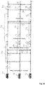
- FIG. 4 shows the typical construction of an on-board network of a modern motor vehicle.
- Reference numeral 151 denotes an engine control unit.
- the reference numeral 152 corresponds to an ESC control unit corresponding to electronic stability control and the reference numeral 153 denotes a transmission control unit.
- Further control devices such as a vehicle dynamics control unit, etc., may be provided in the motor vehicle.
- CAN bus system controller area network
- sensors in the motor vehicle are wheel speed sensors, steering angle sensors, acceleration sensors, rotary data sensors, tire pressure sensors, distance sensors, knock sensors, air sensor sensors, etc.
- the various sensors with which the vehicle is equipped are designated by the reference number 161, 162, 163 in Fig 4 .
- the modern motor vehicle can also have further components such as video cameras 105, e.g. As a reversing camera or as a driver monitoring camera, as well as a LIDAR or RADAR device for the realization of a radar system or for implementing a distance warning or collision warning/avoidance device.
- video cameras 105 e.g. As a reversing camera or as a driver monitoring camera, as well as a LIDAR or RADAR device for the realization of a radar system or for implementing a distance warning or collision warning/avoidance device.
- a navigation system 120 which is also installed in the area of the cockpit, is often distinguished from this.
- the route which is displayed on a map, can of course also be displayed on the display in the cockpit.
- Other components such as a hands-free system, may be present but are not shown in detail.
- Reference numeral 110 denotes an on-board unit.
- This on-board unit 110 corresponds to a communication module via which the vehicle can receive and transmit mobile data.
- this is a mobile radio communication module, e.g. according to the LTE standard. All these devices are assigned to the infotainment area. They are therefore networked via a bus system 102 designed for the special needs of this device category.
- a high speed CAN bus is one example, which could be applied.
- an Ethernet-Bus 108 which connects only the two components driver assistance controller 171 and RADAR device 172.
- the Ethernet-Bus is a choice also for this communication bus 108 due to its higher bandwidth for data transport.
- a LIDAR sensor or a number of cameras and / or ultrasonic sensors could be applied for surrounding observation.
- One Ethernet-Bus adapted to the special needs of car communication is standardized in the IEEE 802.1Q specification.
- the ultrasonic sensor typically is used for a short distance observation, e.g. 3 to 5m.
- the RADAR and LIDAR sensors could be used for scanning a range up to 250 m or 150 m and the cameras cover a range from 30 to 120 m.
- the gateway 140 For the purpose of transmitting the vehicle-relevant sensor data via the communication interface 110 to another vehicle or to a central computer, the gateway 140 is provided. This is connected to the different bus systems 102, 104 and 108. The gateway 140 is adapted to convert the data it receives via the Ethernet-Bus 108 to be converted into the transmission format of the infotainment CAN-bus 102 so that it can be distributed in the packets specified there. For the forwarding of this data to the outside, i.e. to another motor vehicle or to central computer 50, the on-board unit 110 is equipped with the communication interface to receive these data packets and, in turn, to convert them into the transmission format of the correspondingly used mobile radio standard. As shown, the gateway 140 is connected as a central device to the busses 102, 104 as well as 108. It therefore takes all the necessary format conversions if data are to be exchanged between the different bus systems and if required.
- Fig. 5 shows the planning of an evasive maneuver in which the observer car 31 calculates an evasive trajectory TJ due to a preceding car 32 which stands still or brakes heavily.
- the way how to calculate such collision avoiding maneuver is described in a thesis report of Dr. Thomas Maurer titled "Beêt von Mess- und procurdiktionsun Philosophen in der ssenen Eingriffsentscheidung fur Strukture Notbrems- und Ausweichsysteme" at University Duisburg-Essen.
- Fig. 6 shows different illustrations of a driving hose FS.
- a very intuitive illustration is a 3D representation of the driving hose FS. It illustrates the probability for each point in lateral and longitudinal direction that the car will reach that point within the given time interval, usually a few seconds, as mentioned above.
- the upper right illustration is a 2D illustration where the probability is indicated with the strength of the point.
- the 3D representation is not fully correct. More in general for maneuver planning according to the invention a 4D representation of the driving hose is used. One dimension corresponds to the longitudinal direction and the second dimension to the lateral direction. The third dimension corresponds to the time and the fourth dimension to the so-called ego-probability, i.e. the probability that the observer vehicle will reach the corresponding point at the given time. Each cooperating vehicle in the collision avoidance system according to the invention will calculate this sort of 4D driving hose. Another way of interpreting the 4D driving hose is to view it as a trajectory space containing a great variety of possible trajectories the car may take.
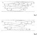
- Fig. 7 shows some 2D projections of such 4D driving hoses for the three cars 31 to 32.
- the drawing is illustrating a typical dangerous overtaking maneuver.
- Car 31 is overtaking the preceding car 32 on the counter lane while another car 33 is coming along and driving in the opposite direction.
- any autonomous driving system should avoid this sort of situation but what is considered here is the case that the driver has taken over control of steering the car and manually forced the car into this situation.
- the collision avoidance system should intervene to avoid a collision. It is a cooperative collision avoidance system and the involved cars communicate to dissolve the dangerous situation.
- Each car will calculate its 4D driving hose and communicate it to the other involved cars.
- Fig. 7 shows the overlap of the 2D projections of the driving hoses of cars 31, 32 and 33.
- each driving hose There are two contours shown of each driving hose.
- the inner contours 31S, 32S and 33S drawn in solid line in each case shows the region which should be safe to go, i.e. where the probability of a collision is really low, e.g. less than 1%.
- the regions from the inner contour onwards to the outer contour 31 U, 32U, 33U are unsafe driving regions and should be avoided.
- this vehicle triggers broadcast message with which the cooperative collision avoidance maneuver planning is started. At the same time it starts a timer with a certain deadline. This deadline timer shall be selected such that no significant changes happens on the road within this time, i.e.
- the same vehicle sends via broadcast its 4-dimensional tensor of its own estimated driving hose which includes the possible trajectories to go.
- all other vehicles in the vicinity, which received the corresponding message evaluate the relevance of this maneuver for themselves.
- all vehicles 31, 32 and 33 will find it relevant. If they find it relevant, they broadcast their own 4D space of possible trajectories linearly combined with at least some or all previously received 4D driving hoses of other partners before the timer set by the first vehicle expires.
- This broadcast includes the generation matrix for the linear combinations.
- Such combinations can follow, for example, the principles of network coding.
- One possible implementation of this scheme is the random linear network code (RLNC).
- the linear combination of trajectory spaces is envisioned to increase the robustness of exchanged information in cases of an error prone channel.
- the broadcast message will be communicated wirelessly in a broadcast channel of the mobile communication sidelink traffic in case of an LTE mobile communication system or in a WLAN channel for WLAN based car to car communication, the linear combination corresponding to linear network coding should definitely improve the robustness.
- the broadcast messages will be submitted in the SL-PSBCH channel.
- the methodology how vehicles access the medium for broadcast can be arbitrary.
- a UE user equipment
- joins a network it goes through a network entry phase.
- the purpose of the network entry phase is for the current UE to transmit a Network Entry Packet (NEP), a one-time special transmission which is meant to inform all the other UEs within range of the current one that it is about to join the network.
- NEP Network Entry Packet
- the slot for the transmission of the NEP is chosen using the Random Access Time-Division Multiple Access (RATDMA) protocol, which "is used when a station needs to allocate a slot, which has not been pre-announced".
- RDDMA Random Access Time-Division Multiple Access
- TDMA self-organised TDMA
- STDMA self-organised TDMA
- MAC layer protocol the well-known time division multiple access method where time slots will be assigned to participants.
- TDMA is the well-known time division multiple access method where time slots will be assigned to participants.
- the RATDMA access is not reliable enough, one possible approach could be that when a vehicle broadcasts its status, it points out who will broadcast next (until all vehicles in the vicinity have broadcasted). This is possible if one bears in mind that under the considered scenario of cooperative or autonomous driving the vehicles anyhow broadcast so-called Cooperative Awareness Messages CAM periodically such that they are aware which other vehicles are in the vicinity.
- each car After having received the 4D driving hoses from all involved cars, each car evaluates the situation and calculates its own safe region and selects from this region an evasive trajectory for its own car to dissolve the dangerous situation. For this, each vehicle decodes the linearly combined 4D driving hoses. At this point, it is assumed that all vehicles will have the same set of 4D spaces. The way this is done, is illustrated in Fig. 8 . It is noted that the 4D driving hoses will be mathematically represented in the form of a tensor.
- each vehicle correlates all received trajectory spaces with its own over space and time to find the mutual global safe region which fulfills certain pre-defined safety requirements. Since each vehicle has the same set of trajectory spaces, the solution found at each vehicle will fulfill the requirements of each vehicle. If the found solution at any vehicle does not fulfill the pre-defined safety requirements, the vehicle informs all other vehicles, that it is not able to successfully complete the maneuver and that the maneuver of collision minimization has to be started instead of collision avoidance.
- Fig. 8 shows the results of the correlation calculation and the solution of the optimization problem for each of the cars 31, 32 and 33. For the abscissa the space and time ST is lined up. On the ordinate the correlation level UC is depicted. The upper region USR corresponds to the unsafe region.
- the lower region SR in which the global minimum lies corresponds to the safe region.
- the hatched sections of the correlation result curves correspond to the safe regions 31 S, 32S and 33S where the corresponding car should stay in order to avoid collision.
- the correlation calculation follows the following steps:
- Fig. 9 finally shows a projection of the mutual safe regions 31 S, 32S, 33S of a driving hose for each car 31, 32, 33 in order to avoid collision.
- Fig. 10 now shows the different phases of the cooperative collision avoidance maneuver.
- Car 31 at step 1 with its sensor equipment detects the risk of a collision.
- car 31 sends out a broadcast message in step 2 to the surrounding vehicles on the road via sidelink communication channel SL-PSBCH.
- a value for a timer setup is communicated, too.
- car 31 sends its own 4D driving hose (space, time and ego-likelihood) in another broadcast message.
- This message further includes the start and end time for a timer setup. These time values are selected such that no significant changes happens on the road within this time.
- the two involved cars 32 and 33 in step 4 setup a timer T1 each with the values which they received in the broadcast message of step 4 and start the timer.
- This timer T1 determines the length of the phase for data collection, i.e. trajectory space exchange phase.
- the two other participants car 32 and car 33 broadcast their own 4D driving hoses.
- each vehicle correlates over time and with its ego preferences all received 4D driving hoses and calculates the mutual safe regions 31 S, 32S and 33S in the manner as explained above. If a car is not able to find a safe region, this car should initiate a change in the CCA state.
- each car selects the preferred trajectory from the determined safe region and sends it to the other involved cars in a broadcast message. If a car did not find a safe region, it would change to CMS state and it would broadcast a corresponding signaling message. All the cars sending such a message and receiving such a message would need to immediately change to the CMS state.
- Another timer T2 is being setup during step 4. This timer may be a relative timer which is dependent from the T1 timer such that timer T2 does not need to be broadcasted.
- Timer T2 sets up a deadline up to when a preferred trajectory from a mutual safe region or a change of state message must have been received from the involved cars. The timer is stopped when a preferred trajectory or a state change message has been received.
- timer T2 expires at step 9 and from an involved car neither the preferred trajectory nor the state change message has come, the recognizing car 33 is sending out a retransmission request broadcast message at step 10.
- Such car also starts a timer T3. With expiration of timer T3 at step 11 the car is triggered to change its state to CMS state. In addition, such car will broadcast an announcement that it has changed to CMS state to stop the cooperative collision avoidance maneuver.
- the found mutual safe region 31S, 32S, 33S based on correlated optima's is being then additionally broadcasted to ensure an additional cross-check whether the found solution is suitable for all vehicles in the vicinity.
- the proposed method and apparatus may be implemented in various forms of hardware, software, firmware, special purpose processors, or a combination thereof.
- Special purpose processors may include application specific integrated circuits (ASICs), reduced instruction set computers (RISCs) and/or field programmable gate arrays (FPGAs).
- ASICs application specific integrated circuits
- RISCs reduced instruction set computers
- FPGAs field programmable gate arrays
- the proposed method and apparatus is implemented as a combination of hardware and software.
- the software is preferably implemented as an application program tangibly embodied on a program storage device.
- the application program may be uploaded to, and executed by, a machine comprising any suitable architecture.
- the machine is implemented on a computer platform having hardware such as one or more central processing units (CPU), a random access memory (RAM), and input/output (I/O) interface(s).
- CPU central processing units
- RAM random access memory
- I/O input/output
- the computer platform also includes an operating system and microinstruction code.
- the various processes and functions described herein may either be part of the microinstruction code or part of the application program (or a combination thereof), which is executed via the operating system.
- various other peripheral devices may be connected to the computer platform such as an additional data storage device and a printing device.
- the elements shown in the figures may be implemented in various forms of hardware, software or combinations thereof. Preferably, these elements are implemented in a combination of hardware and software on one or more appropriately programmed general-purpose devices, which may include a processor, memory and input/output interfaces.
- general-purpose devices which may include a processor, memory and input/output interfaces.
- the phrase "coupled" is defined to mean directly connected to or indirectly connected with through one or more intermediate components. Such intermediate components may include both hardware and software based components.
- the application possibilities for the described methods are not limited to use in the motor vehicle.
- the approach for solving the problem of collision avoidance may also be applied in other areas. Examples include aircrafts and drones, as well as mobile robotics in a wide range of areas.
Priority Applications (4)
| Application Number | Priority Date | Filing Date | Title |
|---|---|---|---|
| EP17191248.8A EP3457382A1 (fr) | 2017-09-15 | 2017-09-15 | Procédé de planification d'une man uvre d'évitement de collision, unité de commande correspondante et véhicule équipé d'une unité de commande ainsi que d'un programme informatique |
| US16/127,339 US20190088133A1 (en) | 2017-09-15 | 2018-09-11 | Method for planning a collision avoidance manuever, corresponding control unit, and vehicle equipped with a control unit and computer program |
| KR1020180108893A KR102106047B1 (ko) | 2017-09-15 | 2018-09-12 | 충돌 회피 조작을 계획하는 방법, 대응하는 제어 유닛 및 제어 유닛뿐만 아니라 컴퓨터 프로그램을 구비하는 차량 |
| CN201811072847.5A CN109501801B (zh) | 2017-09-15 | 2018-09-14 | 计划碰撞避免机动的方法、控制单元、车辆和计算机程序 |
Applications Claiming Priority (1)
| Application Number | Priority Date | Filing Date | Title |
|---|---|---|---|
| EP17191248.8A EP3457382A1 (fr) | 2017-09-15 | 2017-09-15 | Procédé de planification d'une man uvre d'évitement de collision, unité de commande correspondante et véhicule équipé d'une unité de commande ainsi que d'un programme informatique |
Publications (1)
| Publication Number | Publication Date |
|---|---|
| EP3457382A1 true EP3457382A1 (fr) | 2019-03-20 |
Family
ID=59901390
Family Applications (1)
| Application Number | Title | Priority Date | Filing Date |
|---|---|---|---|
| EP17191248.8A Ceased EP3457382A1 (fr) | 2017-09-15 | 2017-09-15 | Procédé de planification d'une man uvre d'évitement de collision, unité de commande correspondante et véhicule équipé d'une unité de commande ainsi que d'un programme informatique |
Country Status (4)
| Country | Link |
|---|---|
| US (1) | US20190088133A1 (fr) |
| EP (1) | EP3457382A1 (fr) |
| KR (1) | KR102106047B1 (fr) |
| CN (1) | CN109501801B (fr) |
Cited By (3)
| Publication number | Priority date | Publication date | Assignee | Title |
|---|---|---|---|---|
| DE102019110040A1 (de) * | 2019-04-16 | 2020-10-22 | Bayerische Motoren Werke Aktiengesellschaft | Steuereinheit und Verfahren zur Erkennung, Klassifizierung und Prädiktion eines Interaktionsbedarfs eines automatisiert fahrenden Fahrzeugs |
| DE102020117887A1 (de) | 2020-07-07 | 2022-01-13 | Audi Aktiengesellschaft | Kraftfahrzeugkontrollsystem, Kraftfahrzeugnetzwerk und Verwendung eines Kraftfahrzeugs |
| DE102022123120A1 (de) | 2022-09-12 | 2024-03-14 | Bayerische Motoren Werke Aktiengesellschaft | Verfahren und vorrichtung zur manöverplanung für ein automatisiertes kraftfahrzeug |
Families Citing this family (14)
| Publication number | Priority date | Publication date | Assignee | Title |
|---|---|---|---|---|
| WO2016147623A1 (fr) * | 2015-03-18 | 2016-09-22 | 日本電気株式会社 | Dispositif de commande de conduite, procédé de de commande de conduite et système de communication de véhicule à véhicule |
| JP7132713B2 (ja) * | 2017-12-28 | 2022-09-07 | 株式会社Soken | 車両走行制御装置、車両走行制御システムおよび車両走行制御方法 |
| CN110667573A (zh) * | 2019-09-02 | 2020-01-10 | 山西省交通科技研发有限公司 | 一种汽车行驶状态风险感知预警系统及其方法 |
| US11958183B2 (en) | 2019-09-19 | 2024-04-16 | The Research Foundation For The State University Of New York | Negotiation-based human-robot collaboration via augmented reality |
| EP4062388A4 (fr) * | 2019-11-22 | 2023-08-09 | Qualcomm Incorporated | Échange d'informations de manoeuvre de véhicule avec fenêtre temporelle |
| CN111127952A (zh) * | 2020-01-07 | 2020-05-08 | 腾讯科技(深圳)有限公司 | 检测潜在交通碰撞的方法、装置和存储介质 |
| EP3859709A1 (fr) * | 2020-01-30 | 2021-08-04 | Volkswagen Ag | Procédé de planification d'une man uvre de conduite coopérative, unité de commande correspondante et véhicule équipé d'une unité de commande ainsi que d'un programme informatique |
| US11496858B2 (en) * | 2020-01-31 | 2022-11-08 | Qualcomm Incorporated | Cooperative event warning system |
| US11603094B2 (en) | 2020-02-20 | 2023-03-14 | Toyota Motor North America, Inc. | Poor driving countermeasures |
| US11527154B2 (en) | 2020-02-20 | 2022-12-13 | Toyota Motor North America, Inc. | Wrong way driving prevention |
| US20210261168A1 (en) * | 2020-02-20 | 2021-08-26 | Toyota Motor North America, Inc. | Transport traffic violation approval |
| DE102020207283A1 (de) | 2020-06-10 | 2021-12-16 | Volkswagen Aktiengesellschaft | Kontrollzentrum, Fahrzeug, Verfahren, Vorrichtung und Computerprogramm zur Übernahme der Kontrolle über ein zu kontrollierendes Fahrzeug |
| US20220315047A1 (en) * | 2021-03-30 | 2022-10-06 | Honda Research Institute Europe Gmbh | Method, system and vehicle with an uncertainty-based lane positioning control |
| DE102021125348A1 (de) * | 2021-09-30 | 2023-03-30 | Ford Global Technologies Llc | Verfahren zum Betreiben eines Fahrassistenzsystems und Fahrassistenzsystem |
Citations (11)
| Publication number | Priority date | Publication date | Assignee | Title |
|---|---|---|---|---|
| EP2473388A1 (fr) * | 2009-08-31 | 2012-07-11 | Toyota Motor Europe NV/SA | Procédé et système de contrôle de véhicule ou de trafic |
| US20130325306A1 (en) | 2012-06-01 | 2013-12-05 | Toyota Motor Eng. & Mftg. N. America, Inc. (TEMA) | Cooperative driving and collision avoidance by distributed receding horizon control |
| US20140369253A1 (en) * | 2013-06-12 | 2014-12-18 | Qualcomm Incorporated | Degree reduction and degree-constrained combining for relaying a fountain code |
| DE102013015028A1 (de) * | 2013-09-10 | 2015-03-12 | Daimler Ag | Verfahren zum Betrieb eines Fahrzeuges |
| EP2950294A1 (fr) * | 2014-05-30 | 2015-12-02 | Honda Research Institute Europe GmbH | Procédé et véhicule avec un système d'assistance au conducteur pour une analyse de scène de trafic fondée sur le risque |
| WO2016020290A1 (fr) | 2014-08-04 | 2016-02-11 | Continental Teves Ag & Co. Ohg | Système pour une conduite de coopération automatisée |
| DE102015221817A1 (de) | 2015-11-06 | 2017-05-11 | Audi Ag | Verfahren zum dezentralen Abstimmen von Fahrmanövern |
| DE102015220481A1 (de) * | 2015-10-21 | 2017-05-11 | Volkswagen Aktiengesellschaft | Verfahren und Vorrichtung in einer Verkehrseinheit zum kooperativen Abstimmen von Fahrmanövern von mindestens zwei Kraftfahrzeugen |
| DE102016011836A1 (de) * | 2016-10-01 | 2017-06-01 | Daimler Ag | Verbesserung der Fahrzeugausrichtung mittels Hinterachslenkung |
| DE102015121353A1 (de) * | 2015-12-08 | 2017-06-08 | Valeo Schalter Und Sensoren Gmbh | Verfahren zum Erkennen einer möglichen Kollision zwischen einem Kraftfahrzeug und einem Objekt unter Berücksichtigung einer räumlichen Unsicherheit, Steuereinrichtung, Fahrerassistenzsystem sowie Kraftfahrzeug |
| DE102016202070A1 (de) * | 2016-02-11 | 2017-08-17 | Volkswagen Aktiengesellschaft | Kraftfahrzeug-Steuervorrichtung und Verfahren zum Ermitteln von Ausweichtrajektorien für ein kollisionsfreies Ausweichmanöver mehrerer Kraftfahrzeuge |
Family Cites Families (7)
| Publication number | Priority date | Publication date | Assignee | Title |
|---|---|---|---|---|
| JP2005227978A (ja) * | 2004-02-12 | 2005-08-25 | Denso Corp | 衝突回避システム |
| DE102007058538A1 (de) * | 2007-12-06 | 2009-06-10 | Robert Bosch Gmbh | Verfahren zum Kontrollieren einer Gefahrensituation im Verkehr |
| KR101406435B1 (ko) * | 2008-07-07 | 2014-06-13 | 현대자동차주식회사 | 충돌 방지 시스템 |
| DE102009045286A1 (de) * | 2009-10-02 | 2011-04-21 | Robert Bosch Gmbh | Verfahren zur Abbildung des Umfelds eines Fahrzeugs |
| EP2306433A1 (fr) * | 2009-10-05 | 2011-04-06 | Nederlandse Organisatie voor toegepast -natuurwetenschappelijk onderzoek TNO | Système et procédé d'évitement des collisions pour véhicule routier et programme d'ordinateur correspondant |
| DE102011086210A1 (de) * | 2011-11-11 | 2013-05-16 | Robert Bosch Gmbh | Verfahren zur Unterstützung eines Fahrers eines Kraftfahrzeugs sowie Vorrichtung zur Durchführung des Verfahrens |
| DE102011087774A1 (de) * | 2011-12-06 | 2013-06-06 | Robert Bosch Gmbh | Verfahren zur Überwachung und Signalisierung einer Verkehrssituation im Umfeld eines Fahrzeuges |
-
2017
- 2017-09-15 EP EP17191248.8A patent/EP3457382A1/fr not_active Ceased
-
2018
- 2018-09-11 US US16/127,339 patent/US20190088133A1/en not_active Abandoned
- 2018-09-12 KR KR1020180108893A patent/KR102106047B1/ko active IP Right Grant
- 2018-09-14 CN CN201811072847.5A patent/CN109501801B/zh active Active
Patent Citations (11)
| Publication number | Priority date | Publication date | Assignee | Title |
|---|---|---|---|---|
| EP2473388A1 (fr) * | 2009-08-31 | 2012-07-11 | Toyota Motor Europe NV/SA | Procédé et système de contrôle de véhicule ou de trafic |
| US20130325306A1 (en) | 2012-06-01 | 2013-12-05 | Toyota Motor Eng. & Mftg. N. America, Inc. (TEMA) | Cooperative driving and collision avoidance by distributed receding horizon control |
| US20140369253A1 (en) * | 2013-06-12 | 2014-12-18 | Qualcomm Incorporated | Degree reduction and degree-constrained combining for relaying a fountain code |
| DE102013015028A1 (de) * | 2013-09-10 | 2015-03-12 | Daimler Ag | Verfahren zum Betrieb eines Fahrzeuges |
| EP2950294A1 (fr) * | 2014-05-30 | 2015-12-02 | Honda Research Institute Europe GmbH | Procédé et véhicule avec un système d'assistance au conducteur pour une analyse de scène de trafic fondée sur le risque |
| WO2016020290A1 (fr) | 2014-08-04 | 2016-02-11 | Continental Teves Ag & Co. Ohg | Système pour une conduite de coopération automatisée |
| DE102015220481A1 (de) * | 2015-10-21 | 2017-05-11 | Volkswagen Aktiengesellschaft | Verfahren und Vorrichtung in einer Verkehrseinheit zum kooperativen Abstimmen von Fahrmanövern von mindestens zwei Kraftfahrzeugen |
| DE102015221817A1 (de) | 2015-11-06 | 2017-05-11 | Audi Ag | Verfahren zum dezentralen Abstimmen von Fahrmanövern |
| DE102015121353A1 (de) * | 2015-12-08 | 2017-06-08 | Valeo Schalter Und Sensoren Gmbh | Verfahren zum Erkennen einer möglichen Kollision zwischen einem Kraftfahrzeug und einem Objekt unter Berücksichtigung einer räumlichen Unsicherheit, Steuereinrichtung, Fahrerassistenzsystem sowie Kraftfahrzeug |
| DE102016202070A1 (de) * | 2016-02-11 | 2017-08-17 | Volkswagen Aktiengesellschaft | Kraftfahrzeug-Steuervorrichtung und Verfahren zum Ermitteln von Ausweichtrajektorien für ein kollisionsfreies Ausweichmanöver mehrerer Kraftfahrzeuge |
| DE102016011836A1 (de) * | 2016-10-01 | 2017-06-01 | Daimler Ag | Verbesserung der Fahrzeugausrichtung mittels Hinterachslenkung |
Non-Patent Citations (1)
| Title |
|---|
| "A reference architecture for CISS/CDAS within the field of cooperative driving", 2014 INTERNATIONAL CONFERENCE ON CONNECTED VEHICLES AND EXPO (ICCVE, 2014 |
Cited By (3)
| Publication number | Priority date | Publication date | Assignee | Title |
|---|---|---|---|---|
| DE102019110040A1 (de) * | 2019-04-16 | 2020-10-22 | Bayerische Motoren Werke Aktiengesellschaft | Steuereinheit und Verfahren zur Erkennung, Klassifizierung und Prädiktion eines Interaktionsbedarfs eines automatisiert fahrenden Fahrzeugs |
| DE102020117887A1 (de) | 2020-07-07 | 2022-01-13 | Audi Aktiengesellschaft | Kraftfahrzeugkontrollsystem, Kraftfahrzeugnetzwerk und Verwendung eines Kraftfahrzeugs |
| DE102022123120A1 (de) | 2022-09-12 | 2024-03-14 | Bayerische Motoren Werke Aktiengesellschaft | Verfahren und vorrichtung zur manöverplanung für ein automatisiertes kraftfahrzeug |
Also Published As
| Publication number | Publication date |
|---|---|
| US20190088133A1 (en) | 2019-03-21 |
| CN109501801B (zh) | 2022-04-29 |
| KR20190031161A (ko) | 2019-03-25 |
| KR102106047B1 (ko) | 2020-04-29 |
| CN109501801A (zh) | 2019-03-22 |
Similar Documents
| Publication | Publication Date | Title |
|---|---|---|
| EP3457382A1 (fr) | Procédé de planification d'une man uvre d'évitement de collision, unité de commande correspondante et véhicule équipé d'une unité de commande ainsi que d'un programme informatique | |
| TWI790260B (zh) | 用於車輛之間協調式車道改變協商之系統及方法 | |
| US11753033B2 (en) | Context-aware navigation protocol for safe driving | |
| US10486701B2 (en) | Driving control device, driving control method and vehicle-to-vehicle communication system | |
| CN110996302B (zh) | 预测通信设备的通信链路的通信的服务质量的方法和装置 | |
| EP3273422A1 (fr) | Dispositif de commande de conduite, procédé de de commande de conduite et système de communication de véhicule à véhicule | |
| CN108834434A (zh) | 用于开始或者执行协同驾驶机动动作的方法、设备和计算机程序 | |
| EP3859709A1 (fr) | Procédé de planification d'une man uvre de conduite coopérative, unité de commande correspondante et véhicule équipé d'une unité de commande ainsi que d'un programme informatique | |
| US11513513B2 (en) | Method for invoking a teleoperated driving session, apparatus for performing the steps of the method, vehicle and computer program | |
| US20200410868A1 (en) | Method for adjusting the speed of vehicles moving in a convoy | |
| US10916128B2 (en) | Method for data communication between at least two participants of a wireless communication system, corresponding control unit and transportation vehicle equipped with a control unit, and computer program | |
| US11755010B2 (en) | Automatic vehicle and method for operating the same | |
| KR20190106844A (ko) | 입력 신호 우선 순위에 따른 자율 주행 제어 방법 및 이를 이용한 자율 주행 시스템 | |
| JP2023520806A (ja) | 遠隔操作運転セッションを呼び出すための方法、コンピュータプログラムおよび装置 | |
| CN113246962A (zh) | 用于自动泊车辅助的车载设备、系统和方法 | |
| US20230316918A1 (en) | Method for communication between road users, and communication system | |
| WO2022102274A1 (fr) | Dispositif terminal, procédé de transmission, et programme informatique | |
| EP4040817A1 (fr) | Procédé d'un centre de commande pour faire fonctionner un véhicule automatisé et véhicule automatisé | |
| EP4050450B1 (fr) | Procédés, programmes informatiques et appareil permettant d'exécuter une session de conduite télécommandée | |
| US20240160219A1 (en) | Automated platooning system and method thereof | |
| JP2023046334A (ja) | 車両走行の遠隔制御システム |
Legal Events
| Date | Code | Title | Description |
|---|---|---|---|
| PUAI | Public reference made under article 153(3) epc to a published international application that has entered the european phase |
Free format text: ORIGINAL CODE: 0009012 |
|
| STAA | Information on the status of an ep patent application or granted ep patent |
Free format text: STATUS: THE APPLICATION HAS BEEN PUBLISHED |
|
| AK | Designated contracting states |
Kind code of ref document: A1 Designated state(s): AL AT BE BG CH CY CZ DE DK EE ES FI FR GB GR HR HU IE IS IT LI LT LU LV MC MK MT NL NO PL PT RO RS SE SI SK SM TR |
|
| AX | Request for extension of the european patent |
Extension state: BA ME |
|
| STAA | Information on the status of an ep patent application or granted ep patent |
Free format text: STATUS: REQUEST FOR EXAMINATION WAS MADE |
|
| 17P | Request for examination filed |
Effective date: 20190920 |
|
| RBV | Designated contracting states (corrected) |
Designated state(s): AL AT BE BG CH CY CZ DE DK EE ES FI FR GB GR HR HU IE IS IT LI LT LU LV MC MK MT NL NO PL PT RO RS SE SI SK SM TR |
|
| STAA | Information on the status of an ep patent application or granted ep patent |
Free format text: STATUS: EXAMINATION IS IN PROGRESS |
|
| 17Q | First examination report despatched |
Effective date: 20201112 |
|
| STAA | Information on the status of an ep patent application or granted ep patent |
Free format text: STATUS: EXAMINATION IS IN PROGRESS |
|
| STAA | Information on the status of an ep patent application or granted ep patent |
Free format text: STATUS: THE APPLICATION HAS BEEN REFUSED |
|
| 18R | Application refused |
Effective date: 20211209 |