EP3456593B1 - Bürstenhalter für eine waschbürste und waschbürste - Google Patents
Bürstenhalter für eine waschbürste und waschbürste Download PDFInfo
- Publication number
- EP3456593B1 EP3456593B1 EP18187888.5A EP18187888A EP3456593B1 EP 3456593 B1 EP3456593 B1 EP 3456593B1 EP 18187888 A EP18187888 A EP 18187888A EP 3456593 B1 EP3456593 B1 EP 3456593B1
- Authority
- EP
- European Patent Office
- Prior art keywords
- brush holder
- brush
- pressure
- fluid
- washing
- Prior art date
- Legal status (The legal status is an assumption and is not a legal conclusion. Google has not performed a legal analysis and makes no representation as to the accuracy of the status listed.)
- Active
Links
Images



Classifications
-
- B—PERFORMING OPERATIONS; TRANSPORTING
- B60—VEHICLES IN GENERAL
- B60S—SERVICING, CLEANING, REPAIRING, SUPPORTING, LIFTING, OR MANOEUVRING OF VEHICLES, NOT OTHERWISE PROVIDED FOR
- B60S3/00—Vehicle cleaning apparatus not integral with vehicles
- B60S3/04—Vehicle cleaning apparatus not integral with vehicles for exteriors of land vehicles
- B60S3/045—Other hand-held cleaning arrangements, e.g. with sponges, brushes, scrapers or the like
- B60S3/047—Other hand-held cleaning arrangements, e.g. with sponges, brushes, scrapers or the like using liquid or gas distributing means
-
- A—HUMAN NECESSITIES
- A46—BRUSHWARE
- A46B—BRUSHES
- A46B11/00—Brushes with reservoir or other means for applying substances, e.g. paints, pastes, water
- A46B11/06—Brushes with reservoir or other means for applying substances, e.g. paints, pastes, water connected to supply pipe or to other external supply means
- A46B11/063—Brushes with reservoir or other means for applying substances, e.g. paints, pastes, water connected to supply pipe or to other external supply means by means of a supply pipe
Definitions
- the present invention relates to a brush holder for a washing brush with a section which has a wall and into which a pressure fluid can be introduced.
- the section In an active state without the application of a fluid pressure generated by the pressure fluid, the section has a first buckling stiffness, with which the section is flexible in the inactive state.
- the invention further relates to a washing brush with such a brush holder and a brush head.
- washing brushes are provided on self-service washing systems, by means of which a customer can wash his vehicle himself.
- these washing brushes In order to prevent people from cleaning their vehicle at a self-service washing station without having to deposit money, it has been proposed to design these washing brushes as articulated brushes. This means that a part of the brush holder in the inactive state is so soft that the brush head hangs limply so that it cannot be guided along a vehicle surface.
- the WO 2014/039619 A2 describes a washing brush, the brush holder of which has a flexible part in which a mechanical slide is pushed forward when fluid pressure is present. This stiffens the flexible part from the inside.
- washing brush A disadvantage of such a washing brush is that it is subject to wear due to the necessary mechanical parts. Furthermore, the washing brush cannot be operated with a central washing water distributor, since the mechanics react very sensitively to different pre-pressures. Such a washing brush is also complicated in construction and can be difficult to dismantle and reassemble in the event of maintenance. In addition, such a washing brush is expensive to manufacture.
- the brush holder according to the invention is characterized in that the pressure fluid is introduced into the section in an active state, the section having a second buckling stiffness in the active state, which is generated in that the pressure fluid introduced into the section applies a fluid pressure directly to the wall of the Exerts section so that the section is substantially inflexible.
- the fluid pressure is therefore exerted directly on the wall of the section.
- the wall of the section is also inherently flexible, i.e. especially flaccid.
- the pressure fluid is solely responsible for stiffening the section.
- the brush holder can be manufactured cheaply.
- no complicated mechanical processes are necessary in the brush holder, which are susceptible to faults and can lead to frequent failure of washing brushes.
- the stiffening of the section is caused in particular by the fact that the fluid pressure applied to the wall of the section causes tensile stress on the section.
- the buckling stiffness that is, the stiffness that the section has compared to kinking, is in particular dependent on the pressure applied, the diameter of the section and the wall thickness of the section.
- the buckling stiffness is characterized in particular by the buckling moment, which indicates the size of the bending moment which has to be applied in order to bend the section. The buckling moment is then achieved when the tensile stress from the pressure is exactly the same as a stress that is generated by a bending process, such as is carried out when the brush holder is pressed against a body surface.
- a brush head which is fastened to the brush holder, to be guided in the active state along a surface of an object, for example a vehicle body.
- the section has a second buckling stiffness, with which the section is inflexible.
- the inactive state in which the section has the first buckling stiffness with which the section is flexible, a brush head cannot be used to clean an object. Because when inactive, the brush head hangs limply. This advantageously prevents a washing brush from being used without prior activation, for example by inserting a coin.
- the section is in particular tubular.
- the tubular design there is in particular a circular ring as a cross section.
- the first buckling stiffness depends on the material used for the section, the diameter of the section and the wall thickness of the section.
- the fluid pressure exerted on the wall of the section is also of importance for the second buckling stiffness. In this way, the buckling stiffness of the same section is changed, even though the section still has the same material.
- the buckling moment at which the section kinks in the active state is in a range from 1 to 6 Nm at a fluid pressure in a range from 2 to 5 bar.
- the buckling moment at which the section buckles in the inactive state is, for example, in a range from 0 to 0.5 Nm.
- the section advantageously kinks even at a low bending moment, so that the brush holder cannot be guided along a body surface in the inactive state.
- the section is a thin-walled and pressure-stable pressure vessel.
- the thin-walled nature of the pressure container can ensure that the section hangs limply when the brush holder is inactive.
- the thickness of the wall of the section is in particular in a range from 0.1 to 3 mm.
- the wall thickness is preferably in a range from 1 mm to 2 mm, in particular 1.6 mm.
- the thin-walled and pressure-stable design of the pressure vessel means that mechanical elements which stiffen the flexible section can be dispensed with.
- the wall of the section is designed in particular in such a way that it withstands a fluid pressure of up to 150 bar.
- the wall of the section withstands a fluid pressure in a range from 2 to 20 bar.
- a pressure in a range of 2 to 20 bar is sufficient to stiffen the section.
- the pressure is advantageously in a range from 5 to 15 bar, preferably in a range from 10 to 15 bar. This advantageously ensures that the brush holder becomes so hard and inflexible that it can be used for cleaning a vehicle without the flexible section of the brush holder bursting when a high pressure is applied.
- the section is in particular made of synthetic fiber, natural fiber and / or an elastomer, e.g. B. rubber.
- the use of these materials can ensure that the pressure vessel is very pressure-stable despite its thin walls and can have the required first and second buckling stiffness.
- the outer skin of the pressure vessel made of synthetic or natural fiber fabric and the inner skin of the pressure vessel is rubberized.
- the piece of tubing can be a piece of flat tubing.
- the piece of hose is a piece of fire hose.
- a flow line is arranged in the brush holder, in which the section is arranged, the pressure fluid being able to be conducted through the section to a brush head which can be fastened to the brush holder.
- the pressure fluid can be a washing fluid. This means that the same fluid can be used to generate the fluid pressure and to clean the vehicle surface. This advantageously contributes to the fact that the operation of a washing brush with such a brush holder can be provided inexpensively.
- a constriction is arranged in the direction of flow of the pressure fluid behind the section, which constricts the pressure fluid in the section in order to generate the fluid pressure.
- the constriction is particularly designed as a throttle.
- the resulting dynamic pressure is dependent on the volume flow of the pressure fluid and the size of the throttle. Pressures of up to 150 bar can arise in the section.
- the brush holder according to the invention advantageously enables the use of such high pressures.
- the throttle advantageously ensures that the fluid pressure required for the stiffening with the flowing fluid can be reliably reached and maintained over the duration of the active state.
- the throttle can be designed, for example, as a spray nozzle in the brush head.
- the throttle is arranged in the brush holder in particular when the washing fluid is used as pressure fluid.
- a pump is used which has a sufficiently high pumping capacity.
- the brush holder has a first end to which a brush head can be fastened, the first end being designed in such a way that no pressure fluid can escape.
- the brush holder also has a second end which is connected to a pressurized fluid reservoir from which the pressurized fluid can be conducted into the section.
- On a separate feed line is arranged over the brush holder, via which a washing fluid can be conducted to the brush head.
- the first end is in particular designed to be closed. This means that the section at the end to which a brush head can be fastened has a further wall which prevents the pressure fluid from escaping.
- the pressure fluid and the washing fluid differ from one another in this embodiment.
- the pressure fluid can be, for example, air, water and / or oil.
- the brush holder is then a closed system with an enclosed volume.
- the washing fluid for cleaning the vehicle surface is fed to the brush head via a separate feed line.
- This configuration is particularly advantageous when the material from which the section is made is not resistant to the composition of the washing fluid.
- Another advantage of this embodiment is that the spray pressure for the washing fluid is independent of the pressure in the section. The spray pressure can be set separately.
- the contact pressure of the brush head against a surface can be determined via a pre-pressure and / or the diameter of the pressure vessel. This advantageously ensures that a maximum force with which the brush head can be pressed against the vehicle surface is not exceeded. This can prevent the surface to be cleaned from being damaged.
- the hardness of the suspension of the brush holder can be determined in particular by means of the length and / or the diameter of the section.
- the shorter the pressure vessel the more rigid the brush holder appears when the section is pressurized.
- the longer the pressure vessel is designed the softer and more resilient the brush holder appears when the section is pressurized.
- the length of the section can range from 3 cm to the full length of the brush holder. For example, if the brush holder is 100 cm long, the section can have a length of 100 cm and thus provide the entire length of the brush holder. However, the length of the section can also be short compared to the entire length of the brush holder.
- the length of the section should be selected so that a washing brush attached to the brush holder does not collide with plastic and / or steel parts of the brush holder.
- the stiffness of the brush holder can be varied in the active state by adjusting the admission pressure. With this configuration, the strength with which the brush head must be pressed against the surface of the vehicle in order to achieve a cleaning effect can be adjusted.
- the invention further relates to a washing brush with such a brush holder and a brush head which is attached to one end of the brush holder.
- the washing brush has all the advantages of the brassiere according to the invention.
- the invention relates to a washing system with a washing brush according to the invention, a pressurized fluid reservoir and a pump which pumps the pressurized fluid located in the pressurized fluid reservoir into a brush holder of the washing brush.
- the washing brush 1 can be used in particular for cleaning a vehicle. It is arranged, for example, in a self-service washing system and, due to the design of the brush holder 2, can only be used if a deposit has been registered.
- the washing brush 1 comprises a brush head 4 at one end.
- the brush head 4 is designed to be guided along the surface of a vehicle.
- a washing fluid 7 can escape from the brush head 4, which is applied by means of the bristles of the brush head 4 the surface of the vehicle body can be distributed.
- the washing brush 1 is connected to a reservoir, in which the washing fluid 7 is located, via a feed line 5.
- the lead 5 ends in the brush holder.
- the washing brush 1 further comprises a brush holder 2 according to the invention.
- the brush holder 2 comprises a rigid section 2.1 and a flexible section 2.2.
- the rigid section 2.1 of the brush holder 2 is designed to be picked up by one person in order to guide the entire washing brush 1.
- an engagement or a handle can be arranged on the rigid section 2.1.
- the flexible section 2.2 of the brush holder 2 is designed in particular as a thin-walled and pressure-stable pressure container.
- the pressure vessel 2.2 is a flexible piece of hose, which is made of plastic fibers, natural material fibers and / or an elastomer, for. B. rubber is made. Through the use of these materials, the pressure stability can be ensured despite the thin walls of the pressure vessel 2.2.
- the wall thickness of the pressure vessel 2.2 is in particular 1.6 mm
- Figure 1 shows the washing brush 1 in an inactive state. This is when there is no fluid pressure on the brush holder 2.
- the pressure vessel 2.2 In the inactive state, the pressure vessel 2.2 has a first buckling stiffness, at which the pressure vessel 2.2 is flexible.
- the value that the buckling stiffness has in the inactive state is dependent on the material used for the pressure vessel 2.2 and on the cross section that the pressure vessel 2.2 has.
- the pressure vessel 2.2 is designed like a hose.
- the cross section can then be that of a circular ring or that of an ellipse ring, depending on the design of the hose piece.
- the weight of the brush head 4 exerts a bending moment on the pressure vessel 2.2 which is greater than the buckling moment of the pressure vessel 2.2 in the inactive state. As a result, the brush head 4 hangs limply from the brush holder 2. The washing brush 1 can therefore not be used in the inactive state for cleaning a vehicle surface.
- the washing fluid 7 is pumped into the brush holder 2 by means of a pump.
- the washing fluid 7 is introduced through the rigid section 2.1 into the pressure vessel 2.2.
- the washing fluid 7 also has the function of the pressure fluid.
- FIG. 2 shows the washing brush 1 in an active state. This is when the pressure fluid, in the present example the washing fluid 7, has been introduced into the brush holder 2.
- the pressure vessel 2.2 is supplied with pressure fluid by the pump 6 via an inlet side S1.
- the pump 6 is able to generate a pressure p 1 in a range from 5 to 15 bar at a desired volume flow V 1 .
- the volume flow V 1 is dimensioned such that the washing brush 1 is sufficiently irrigated for the car washing process.
- the pressure p 1 is not necessary to enable the cleaning of a vehicle, but to stiffen the pressure vessel 2.2. This happens because the pressure vessel 2.2 has a constriction 3 on its output side S2.
- the throttle 3 from the Figures 1 and 2 shown which is dimensioned such that the desired volume flow only flows into the brush head 4 with a very low residual pressure p 2 , which is less than 1 bar.
- the throttle 3 can in particular be designed as a spray nozzle in the brush head 4.
- the differential pressure ⁇ p between p 1 and p 2 acts in the form of dynamic pressure on the mechanical structure of the pressure vessel 2.2.
- the dynamic pressure acts uniformly on all surfaces of the pressure vessel 2.2 and causes the pressure vessel 2.2, which otherwise hangs slackly, to stand up.
- the pressure on the end face A causes a tensile stress in the x direction in the jacket cross section of the pressure container 2.2, which in Figure 6 is shown.
- the tensile stress is dependent on the jacket cross section, the diameter D, the resulting end face A and the pressure ⁇ p.
- the pressure vessel 2.2 is now loaded with a bending moment M B , as happens when the washing brush head 4 is pressed against the body surface of a vehicle, a stress curve from bending is superimposed on the stress curve from the pressure.
- the tension on the lateral surface M F is added on one side S3 of the pressure vessel 2.2, whereas the tension on the other side S4 of the pressure vessel 2.2 is reduced to the lateral surface M F.
- the pressure vessel 2.2 is slowly loaded with a bend, this occurs without any significant deformation until the bend tensile stress and the compressive tensile stress have exactly the same size.
- the bending moment in this condition is called the buckling moment.
- the wall of the pressure vessel 2.2 deforms and buckles.
- the pressure vessel 2.2 loses its cylindrical shape and can no longer be guided specifically on a body surface of a vehicle.
- the pressure container 2.2 orients itself in such a way that it represents an extension to the first section 2.1 of the brush holder 2.
- Section 2.2 of the brush holder 2 is stiffened. It follows from this that the washing brush 1 can be used to clean the vehicle surface. With other geometries of section 2.2, however, other forms of stiffened section 2.2 can also be realized.
- the fluid pressure that the pressure vessel 2.2 has to endure is up to 20 bar. Adequate stiffening of the pressure vessel 2.2 can already be achieved with a pressure which is in a range from 2 to 3 bar. In the present exemplary embodiment, however, a higher fluid pressure is set. It is in particular in a range from 5 to 15 bar, preferably in a range from 10 to 15 bar. As a result, the pressure container 2.2 becomes so hard and inflexible that the washing brush 1 can be guided along the surface of a vehicle.
- the length of the pressure vessel 2.2 is, for example, 20 cm.
- the length of the pressure container 2.2 can be in a range from 3 cm to the full length of the brush holder 2.
- the hardness of the suspension can vary over the length of the pressure vessel 2.2 the entire washing brush 1 can be set. The longer the pressure vessel 2.2 is designed, the more resilient its effect. In this way, the contact pressure can be kept constant.
- the length of the pressure vessel 2.2 can be variable, for example.
- a hose can be passed through the rigid section 2.1 of the brush holder 2 and is partially led out at one end of the rigid section 2.1.
- the feed line 5 can be guided through the rigid section 2.1 of the brush holder 2.
- the feed line is then at the same time a flow line in which the pressure vessel is arranged.
- the part of the flow line 5 which hangs out of the rigid section 2.1 is the pressure vessel 2.2.
- the length of the pressure vessel 2.2 can be varied by pulling the flow line 5 further out of the rigid section 2.1 or passing it further into the rigid section 2.1.
- the rigid section 2.1 is formed, for example, by a tube through which the pressure vessel 2.2 can be guided.
- the pressure vessel 2.2 formed by a piece of hose is not passed through the tube 2.1, but is connected to the tube 2.1 at one end in a liquid-tight manner. Furthermore, the second buckling stiffness of the pressure container 2.2 can be changed during operation of the washing brush 1 by changing the pump admission pressure.
- the pump pre-pressure can also be used to regulate the maximum contact pressure at which the washing brush 1 should yield. This can also be determined via the diameter of the pressure vessel 2.2.
- the washing brush 1 with the brush holder 2, the pump 6 and the washing fluid reservoir form a first exemplary embodiment of a washing system 10 according to the invention.
- the brush holder 2 of the washing brush 1 is designed as a closed system with an enclosed volume.
- the brush holder 2 is closed at the end at which the brush head 4 is arranged, that is to say, for example, with an additional end wall.
- the brush holder 2 is connected to a separately provided reservoir of a pressure fluid 8.
- a pressure fluid 8 In this case, water, air and / or oil, for example, is used as the pressure fluid 8.
- air from a pressure bottle is used as the pressure fluid 8.
- the washing fluid 7 required for cleaning the vehicle can then not be passed through the brush holder 2 to the brush head 4.
- a separate feed line 9 is therefore led along the outside of the brush holder 2 to the brush head 4.
- a throttle 3 for accumulating the pressure fluid 8 is not necessary.
- the spray pressure with which the washing fluid flows out of the feed line 9 is independent of the pressure prevailing in the pressure vessel.
- the spray pressure can be set separately.
- the feed line 9 for the washing fluid can also be guided within the brush holder 2.
- a passage is then arranged at the closed end of the brush holder 2, through which the feed line 9 can be passed. Seals must then be attached to this passage, which can withstand the pressure applied to the pressure vessel 2.2, so that no pressure fluid 8 can escape at the end to which the brush head 4 is attached.
- the washing brush 1 with the brush holder 2, the pump 6, the pressure fluid reservoir 8 and the washing fluid reservoir form a second exemplary embodiment of a washing system 11 according to the invention.
- the entire pressure p1 then acts as a dynamic pressure, since no fluid can flow off to the brush head 4 on an outlet side.
- the two exemplary embodiments can be combined with one another with regard to the detailed design of the brush holder 2, as far as its buckling rigidity, length, suspension and contact pressure are concerned.
Landscapes
- Engineering & Computer Science (AREA)
- Mechanical Engineering (AREA)
- Brushes (AREA)
Description
- Die vorliegende Erfindung betrifft einen Bürstenhalter für eine Waschbürste mit einem Abschnitt, welcher eine Wand aufweist und in welchen ein Druckfluid einleitbar ist. Der Abschnitt weist in einem aktiven Zustand ohne Anliegen eines von dem Druckfluid erzeugten Fluiddruckes eine erste Knicksteifigkeit auf, mit welcher der Abschnitt im inaktiven Zustand biegeflexibel ist. Ferner betrifft die Erfindung eine Waschbürste mit einem solchen Bürstenhalter und einem Bürstenkopf.
- An Selbstbedienungs-Waschanlagen werden Waschbürsten zur Verfügung gestellt, mittels welchen ein Kunde sein Fahrzeug selbst waschen kann. Um zu verhindern, dass Personen ihr Fahrzeug ohne Geldeinwurf an einem Selbstbedienungs-Waschplatz reinigen können, wurde vorgeschlagen, diese Waschbürsten als Knickbürsten auszugestalten. Dies bedeutet, dass ein Teil des Bürstenhalters im nicht aktiven Zustand so weich ist, dass der Bürstenkopf schlaff herunterhängt, so dass er nicht entlang einer Fahrzeugoberfläche geführt werden kann.
- Die
WO 2014/039619 A2 beschreibt hierzu eine Waschbürste, deren Bürstenhalter einen flexiblen Teil aufweist, in welchen ein mechanischer Schieber nach vorne geschoben wird, wenn ein Fluiddruck anliegt. Dadurch wird der flexible Teil von innen versteift. - Nachteilig an einer solchen Waschbürste ist, dass sie aufgrund der notwendigen mechanischen Teile verschleißbehaftet ist. Weiterhin kann die Waschbürste nicht mit einem zentralen Waschwasserverteiler betrieben werden, da die Mechanik sehr empfindlich auf unterschiedliche Vordrücke reagiert. Eine solche Waschbürste ist außerdem kompliziert im Aufbau und kann im Wartungsfall schwer demontiert und wieder montiert werden. Zudem ist eine solche Waschbürste teuer in der Herstellung.
- Es ist daher die Aufgabe der vorliegenden Erfindung, einen Bürstenhalter und eine Waschbürste der eingangs genannten Art bereitzustellen, welche kostengünstig herzustellen und einfach zu warten sind.
- Diese Aufgabe wird erfindungsgemäß durch einen Bürstenhalter mit den Merkmalen des Anspruchs 1 und eine Waschbürste mit den Merkmalen des Anspruchs 14 gelöst. Vorteilhafte Aus- und Weiterbildungen ergeben sich aus den abhängigen Ansprüchen.
- Der erfindungsgemäße Bürstenhalter ist dadurch gekennzeichnet, dass in einem aktiven Zustand in den Abschnitt das Druckfluid eingeleitet ist, wobei der Abschnitt im aktiven Zustand eine zweite Knicksteifigkeit aufweist, welche dadurch erzeugt wird, dass das in den Abschnitt eingeleitete Druckfluid einen Fluiddruck direkt auf die Wand des Abschnitts ausübt, so dass der Abschnitt im Wesentlichen biegeunflexibel ist.
- Erfindungsgemäß wird der Fluiddruck also direkt auf die Wand des Abschnitts ausgeübt. Zwischen dem Druckfluid und der Wand des Abschnitts befinden sich keine zusätzlichen Bauteile, die eine Versteifung des Abschnitts hervorrufen. Auch die Wand des Abschnitts ist an sich biegeflexibel, d.h. insbesondere schlaff. Das Druckfluid ist alleine für die Versteifung des Abschnitts verantwortlich. Vorteilhafterweise kann der Bürstenhalter dadurch günstig hergestellt werden. Zudem sind keine komplizierten mechanischen Vorgänge in dem Bürstenhalter notwendig, die störanfällig sind und zu einem häufigen Ausfall von Waschbürsten führen können.
- Die Versteifung des Abschnitts wird insbesondere dadurch hervorgerufen, dass der an der Wand des Abschnitts anliegende Fluiddruck eine Zugspannung auf den Abschnitt bewirkt. Die Knicksteifigkeit, also die Steifigkeit, die der Abschnitt gegenüber einem Abknicken aufweist, ist dabei insbesondere abhängig von dem anliegenden Druck, dem Durchmesser des Abschnitts und der Wanddicke des Abschnitts. Die Knicksteifigkeit ist dabei insbesondere durch das Knickmoment, welches die Größe des Biegemoments angibt, welches aufgebracht werden muss, um den Abschnitt abzuknicken, charakterisiert. Das Knickmoment wird dabei dann erreicht, wenn die Zugspannung aus dem Druck exakt gleich ist zu einer Spannung, die von einem Biegevorgang, wie er beispielsweise bei dem Andrücken des Bürstenhalters an eine Karosserieoberfläche vorgenommen wird, erzeugt wird.
- Weiterhin wird es trotz dem Fehlen zusätzlicher mechanischer Bauteile möglich, dass ein Bürstenkopf, welcher an dem Bürstenhalter befestigt ist, im aktiven Zustand entlang einer Oberfläche eines Gegenstandes, beispielsweise einer Fahrzeugkarosserie, geführt werden kann. Denn der Abschnitt weist eine zweite Knicksteifigkeit auf, mit welcher der Abschnitt biegeunflexibel ist. Im inaktiven Zustand hingegen, in welchem der Abschnitt die erste Knicksteifigkeit aufweist, mit welcher der Abschnitt biegeflexibel ist, kann ein Bürstenkopf nicht zum Reinigen eines Gegenstandes verwendet werden. Denn im inaktiven Zustand hängt der Bürstenkopf schlaff herab. Vorteilhafterweise kann dadurch verhindert werden, dass eine Waschbürste ohne vorherige Aktivierung, beispielsweise durch Münzeinwurf, verwendet werden kann.
- Der Abschnitt ist insbesondere schlauchförmig ausgebildet. Bei der schlauchförmigen Ausbildung ergibt sich insbesondere ein Kreisring als Querschnitt.
- Die erste Knicksteifigkeit ist abhängig von dem für den Abschnitt verwendeten Material, dem Durchmesser des Abschnitts und der Wandstärke des Abschnitts. Für die zweite Knicksteifigkeit ist zusätzlich der auf die Wand des Abschnitts ausgeübte Fluiddruck von Belang. So wird die Knicksteifigkeit desselben Abschnitts verändert, obwohl der Abschnitt nach wie vor das gleiche Material aufweist.
- Insbesondere liegt das Knickmoment, bei dem der Abschnitt im aktiven Zustand abknickt, bei einem Fluiddruck in einem Bereich von 2 bis 5 bar in einem Bereich von 1 bis 6 Nm.
- Das Knickmoment, bei dem der Abschnitt im inaktiven Zustand knickt, liegt beispielsweise in einem Bereich von 0 bis 0,5 Nm. Der Abschnitt knickt im inaktiven Zustand vorteilhafterweise bereits bei einem geringen Biegemoment, so dass der Bürstenhalter im inaktiven Zustand nicht entlang einer Karosserieoberfläche geführt werden kann.
- In einer Ausgestaltung ist der Abschnitt ein dünnwandiger und druckstabiler Druckbehälter. Die Dünnwandigkeit des Druckbehälters kann dabei gewährleisten, dass der Abschnitt im inaktiven Zustand des Bürstenhalters schlaff herabhängt. Dabei liegt die Dicke der Wand des Abschnitts insbesondere in einem Bereich von 0,1 bis 3 mm. Bevorzugt liegt die Wanddicke in einem Bereich von 1 mm bis 2 mm, insbesondere bei 1,6 mm. Durch die dünnwandige und druckstabile Ausgestaltung des Druckbehälters kann auf mechanische Elemente, welche den flexiblen Abschnitt versteifen, verzichtet werden.
- Die Wand des Abschnitts ist insbesondere derart ausgestaltet, dass sie einem Fluiddruck von bis zu 150 bar standhält. Insbesondere hält die Wand des Abschnitts einem Fluiddruck in einem Bereich von 2 bis 20 bar stand. Zur Versteifung des Abschnitts ist dabei insbesondere ein Druck in einem Bereich von 2 bis 20 bar ausreichend. Der Druck liegt vorteilhafterweise in einem Bereich von 5 bis 15 bar, bevorzugt in einem Bereich von 10 bis 15 bar. Dadurch kann vorteilhafterweise gewährleistet werden, dass der Bürstenhalter so hart und unflexibel wird, dass er zur Reinigung eines Fahrzeugs verwendet werden kann, ohne dass der flexible Abschnitt des Bürstenhalters bei Anliegen eines hohen Druckes platzt.
- Der Abschnitt ist insbesondere aus Kunstfasergewebe, Naturfasergewebe und/oder einem Elastomer, z. B. Gummi, gefertigt. Durch die Verwendung dieser Materialien kann gewährleistet werden, dass der Druckbehälter trotz seiner dünnen Wände sehr druckstabil ist und die geforderte erste und zweite Knicksteifigkeit aufweisen kann. Insbesondere ist die Außenhaut des Druckbehälters aus Kunst- oder Naturfasergewebe und die Innenhaut des Druckbehälters gummiert. Das Schlauchstück kann dabei ein Flachschlauchstück sein. Insbesondere ist das Schlauchstück ein Feuerwehrschlauchstück.
- In einer Ausgestaltung ist in dem Bürstenhalter eine Durchflussleitung angeordnet, in welcher der Abschnitt angeordnet ist, wobei das Druckfluid durch den Abschnitt zu einem an dem Bürstenhalter befestigbaren Bürstenkopf leitbar ist. Hierbei kann das Druckfluid ein Waschfluid sein. Dies bedeutet, dass das gleiche Fluid zur Erzeugung des Fluiddruckes und zur Reinigung der Fahrzeugoberfläche verwendet werden kann. Dies trägt vorteilhafterweise dazu bei, dass der Betrieb einer Waschbürste mit einem solchen Bürstenhalter kostengünstig bereitgestellt werden kann.
- In einer weiteren Ausgestaltung ist in Durchflussrichtung des Druckfluides hinter dem Abschnitt eine Verengung angeordnet, welche das Druckfluid in dem Abschnitt anstaut, um den Fluiddruck zu erzeugen. Die Verengung ist dabei insbesondere als Drossel ausgebildet. Der hierbei anfallende Staudruck ist dabei abhängig von dem Volumenstrom des Druckfluides und der Größe der Drossel. In dem Abschnitt können dabei Drücke von bis zu 150 bar entstehen. Üblicherweise wird es vermieden, flexibel ausgebildete Schlauchstücke mit solch hohen Drücken zu beaufschlagen, um ein Platzen des Schlauchstückes zu vermeiden. Der erfindungsgemäße Bürstenhalter ermöglicht vorteilhafterweise die Verwendung solch hoher Drücke. Die Drossel sorgt vorteilhafterweise dafür, dass der benötigte Fluiddruck für die Versteifung mit dem fließenden Fluid zuverlässig erreicht und über die Dauer des aktiven Zustandes gehalten werden kann. Die Drossel kann beispielsweise als Sprühdüse in dem Bürstenkopf ausgestaltet sein. Die Drossel wird insbesondere dann in dem Bürstenhalter angeordnet, wenn das Waschfluid als Druckfluid verwendet wird. Um den Druck für die Versteifung zu erhalten, wird dann eine Pumpe verwendet, die eine ausreichend hohe Pumpleistung aufweist.
- In einer anderen Ausgestaltung weist der Bürstenhalter ein erstes Ende auf, an welchem ein Bürstenkopf befestigbar ist, wobei das erste Ende derart ausgestaltet ist, dass kein Druckfluid austreten kann. Der Bürstenhalter weist zudem ein zweites Ende auf, welches mit einem Druckfluidreservoir verbunden ist, aus welchem das Druckfluid in den Abschnitt leitbar ist. An dem Bürstenhalter ist eine separate Zuleitung angeordnet, über welche ein Waschfluid zu dem Bürstenkopf leitbar ist. Das erste Ende ist insbesondere geschlossen ausgestaltet. Dies bedeutet, dass der Abschnitt an dem Ende, an welchem ein Bürstenkopf befestigbar ist, eine weitere Wand aufweist, welche den Austritt des Druckfluides verhindert. Das Druckfluid und das Waschfluid unterscheiden sich in dieser Ausgestaltung voneinander. Das Druckfluid kann beispielsweise Luft, Wasser und/oder Öl sein. Bei dem Bürstenhalter handelt es sich dann um ein geschlossenes System mit einem eingeschlossenen Volumen. Das Waschfluid zum Reinigen der Fahrzeugoberfläche wird über eine separate Zuleitung zum Bürstenkopf geleitet. Diese Ausgestaltung ist insbesondere dann vorteilhaft, wenn das Material, aus dem der Abschnitt gefertigt ist, unbeständig gegenüber der Zusammensetzung des Waschfluides ist. Ein weiterer Vorteil dieser Ausgestaltung ist, dass der Sprühdruck für das Waschfluid unabhängig von dem Druck im Abschnitt ist. Der Sprühdruck kann separat eingestellt werden.
- Insbesondere kann die Anpresskraft des Bürstenkopfes an eine Oberfläche über einen Vordruck und/oder den Durchmesser des Druckbehälters bestimmbar sein. Dadurch wird vorteilhafterweise gewährleistet, dass eine Maximalkraft, mit welcher der Bürstenkopf an die Fahrzeugoberfläche gepresst werden kann, nicht überschritten wird. Hierdurch kann verhindert werden, dass die zu reinigende Oberfläche Schaden nimmt.
- Die Härte der Federung des Bürstenhalters ist insbesondere mittels der Länge und/oder des Durchmessers des Abschnitts bestimmbar. Je kürzer der Druckbehälter ausgestaltet ist, desto starrer wirkt der Bürstenhalter, wenn der Abschnitt druckbeaufschlagt ist. Je länger hingegen der Druckbehälter ausgestaltet ist, desto weicher und federnder wirkt der Bürstenhalter, wenn der Abschnitt druckbeaufschlagt ist. Dabei kann die Länge des Abschnitts in einem Bereich von 3 cm bis zu der vollständigen Länge des Bürstenhalters liegen. Ist der Bürstenhalter beispielsweise 100 cm lang, kann der Abschnitt eine Länge von 100 cm aufweisen und somit die gesamte Länge des Bürstenhalters bereitstellen. Die Länge des Abschnitts kann jedoch auch im Vergleich zur gesamten Länge des Bürstenhalters kurz sein. Insbesondere sollte die Länge des Abschnitts so gewählt werden, dass eine an dem Bürstenhalter befestigte Waschbürste nicht mit Kunststoff- und/oder Stahlteilen des Bürstenhalters zusammenstößt. Bei einer langen federnden Variante des Bürstenhalters kann durch eine Anpassung des Vordruckes die Steifigkeit des Bürstenhalters im aktiven Zustand variiert werden. Durch diese Ausgestaltung kann die Festigkeit, mit welcher der Bürstenkopf an die Oberfläche des Fahrzeugs gedrückt werden muss, um eine reinigende Wirkung zu erzielen, angepasst werden.
- Die Erfindung betrifft ferner eine Waschbürste mit einem solchen Bürstenhalter und einem Bürstenkopf, der an einem Ende des Bürstenhalters befestigt ist. Die Waschbürste weist dabei alle Vorteile des erfindungsgemäßen Büstenhalters auf.
- Zudem betrifft die Erfindung ein Waschsystem mit einer erfindungsgemäßen Waschbürste, einem Druckfluidreservoir und einer Pumpe, die das in dem Druckfluidreservoir befindliche Druckfluid in einen Bürstenhalter der Waschbürste pumpt.
- Die Erfindung wird nun anhand von Ausführungsbeispielen mit Bezug zu den beigefügten Zeichnungen erläutert.
- Figur 1
- zeigt ein erstes Ausführungsbeispiel einer erfindungsgemäßen Waschbürste mit einem erfindungsgemäßen Bürstenhalter im inaktiven Zustand,
- Figur 2
- zeigt die erfindungsgemäße Waschbürste mit dem erfindungsgemäßen Bürstenhalter des ersten Ausführungsbeispiels im aktiven Zustand,
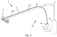
- Figur 3
- zeigt ein zweites Ausführungsbeispiel der erfindungsgemäßen Waschbürste,
- Figuren 4 bis 6
- zeigen die Abläufe innerhalb eines Druckbehälters des erfindungsgemäßen Bürstenhalters, und
- Figur 7
- zeigt den Verlauf des Knickmomentes in Abhängigkeit von einem Staudruck im Inneren des Druckbehälters.
- Mit Bezug zu den
Figuren 1 und 2 wird ein Ausführungsbeispiel für eine erfindungsgemäße Waschbürste 1 mit einem erfindungsgemäßen Bürstenhalter 2 erläutert. - Die Waschbürste 1 kann insbesondere zur Reinigung eines Fahrzeugs verwendet werden. Sie ist beispielsweise in einer Selbstbedienung-Waschanlage angeordnet und kann aufgrund der Ausgestaltung des Bürstenhalters 2 nur dann verwendet werden, wenn ein Geldeinwurf registriert worden ist.
- Die Waschbürste 1 umfasst an einem Ende einen Bürstenkopf 4. Der Bürstenkopf 4 ist dazu ausgestaltet, entlang der Oberfläche eines Fahrzeugs geführt zu werden. Hierzu kann an dem Bürstenkopf 4 ein Waschfluid 7 austreten, welches mittels der Borsten des Bürstenkopfes 4 auf der Oberfläche der Fahrzeugkarosserie verteilt werden kann. Die Waschbürste 1 ist hierzu mit einem Reservoir, in welchem sich das Waschfluid 7 befindet, über eine Zuleitung 5 verbunden. Die Zuleitung 5 endet dabei in dem Bürstenhalter.
- Die Waschbürste 1 umfasst weiterhin einen erfindungsgemäßen Bürstenhalter 2. Der Bürstenhalter 2 umfasst einen starr ausgebildeten Abschnitt 2.1 und einen flexiblen Abschnitt 2.2. Der starre Abschnitt 2.1 des Bürstenhalters 2 ist dazu ausgebildet, von einer Person in die Hand genommen zu werden, um die gesamte Waschbürste 1 zu führen. Hierzu kann beispielsweise ein Eingriff oder ein Griff an dem starren Abschnitt 2.1 angeordnet sein.
- Der flexible Abschnitt 2.2 des Bürstenhalters 2 ist insbesondere als dünnwandiger und druckstabiler Druckbehälter ausgestaltet. Insbesondere ist der Druckbehälter 2.2 ein flexibles Schlauchstück, welches aus Kunststofffasern, Naturstofffasern und/oder einem Elastomer, z. B. Gummi gefertigt ist. Durch die Verwendung dieser Materialien kann die Druckstabilität trotz der Dünnwandigkeit des Druckbehälters 2.2 gewährleistet werden. Die Wanddicke des Druckbehälters 2.2 liegt insbesondere bei 1,6 mm
-
Figur 1 zeigt die Waschbürste 1 in einem inaktiven Zustand. Dieser liegt vor, wenn kein Fluiddruck an dem Bürstenhalter 2 anliegt. Der Druckbehälter 2.2 weist im inaktiven Zustand eine erste Knicksteifigkeit auf, bei welcher der Druckbehälter 2.2 biegeflexibel ist. Der Wert, den die Knicksteifigkeit im inaktiven Zustand aufweist ist dabei abhängig von dem für den Druckbehälter 2.2 verwendeten Material und von dem Querschnitt, den der Druckbehälter 2.2 aufweist. Beispielsweise ist der Druckbehälter 2.2 schlauchartig ausgestaltet. Der Querschnitt kann dann der eines Kreisringes oder der eines Ellipsenringes, je nach Ausgestaltung des Schlauchstückes, sein. - Dadurch, dass der Druckbehälter 2.2 im inaktiven Zustand biegeflexibel ist, übt das Gewicht des Bürstenkopfes 4 ein Biegemoment auf den Druckbehälter 2.2 aus, welches größer ist als das Knickmoment des Druckbehälters 2.2 im inaktiven Zustand. Dadurch hängt der Bürstenkopf 4 schlaff von dem Bürstenhalter 2 herab. Die Waschbürste 1 kann daher im inaktiven Zustand nicht zur Reinigung einer Fahrzeugoberfläche verwendet werden.
- Wird ein Münzeinwurf registriert, wird das Waschfluid 7 über eine Pumpe in den Bürstenhalter 2 gepumpt. Dabei wird das Waschfluid 7 durch den starren Abschnitt 2.1 in den Druckbehälter 2.2 eingeleitet. Das Waschfluid 7 hat dabei zugleich die Funktion des Druckfluides.
-
Figur 2 zeigt die Waschbürste 1 in einem aktiven Zustand. Dieser liegt vor, wenn das Druckfluid, im vorliegenden Beispiel das Waschfluid 7, in den Bürstenhalter 2 eingeleitet wurde. - Mit Bezug zu den
Figuren 4 bis 6 wird die Funktionsweise des Druckbehälters 2.2 des erfindungsgemäßen Bürstenhalters 2 im Detail erläutert, jedoch ohne die Erfindung auf dieses Erklärungsmodell für das Erzeugen der Knicksteifigkeit zu beschränken. Das Erklärungsmodell enthält auch Vereinfachungen, die Randeffekte außer Acht lassen. - Der Druckbehälter 2.2 wird im aktiven Zustand über eine Zulaufseite S1 von der Pumpe 6 mit Druckfluid versorgt. Die Pumpe 6 ist dabei in der Lage, einen Druck p1 in einem Bereich von 5 bis 15 bar bei einem gewünschten Volumenstrom V1 zu erzeugen. Der Volumenstrom V1 ist so bemessen, dass die Waschbürste 1 ausreichend für den Autowaschprozess bewässert ist. Der Druck p1 ist dabei nicht notwendig, um die Reinigung eines Fahrzeugs zu ermöglichen, sondern um den Druckbehälter 2.2 zu versteifen. Dies geschieht dadurch, dass der Druckbehälter 2.2 auf seiner Ausgangsseite S2 eine Verengung 3 aufweist. Im Beispiel der
Figur 4 ist hierzu insbesondere die Drossel 3 aus denFiguren 1 und 2 gezeigt, die so dimensioniert ist, dass der gewünschte Volumenstrom nur noch mit sehr geringem Restdruck p2, der kleiner als 1 bar ist, in den Bürstenkopf 4 strömt. Die Drossel 3 kann dabei insbesondere als Sprühdüse in dem Bürstenkopf 4 ausgestaltet sein. Der Differenzdruck Δp zwischen p1 und p2 wirkt in Form von Staudruck auf die mechanische Struktur des Druckbehälters 2.2. Der Staudruck wirkt gleichmäßig auf alle Flächen des Druckbehälters 2.2 und führt dazu, dass sich der ansonsten schlaff herabhängende Druckbehälter 2.2 aufrichtet. Der Druck auf die Stirnfläche A bewirkt dabei eine Zugspannung in x-Richtung im Mantelquerschnitt des Druckbehälters 2.2, der inFigur 6 gezeigt ist. Die Zugspannung ist dabei abhängig vom Mantelquerschnitt, dem Durchmesser D, der daraus resultierenden Stirnfläche A und dem Druck Δp. - Wird nun der Druckbehälter 2.2 mit einem Biegemoment MB belastet, wie dies bei einem Andrücken des Waschbürstenkopfes 4 an die Karosserieoberfläche eines Fahrzeugs geschieht, wird dem Spannungsverlauf aus dem Druck ein Spannungsverlauf aus Biegung überlagert. Dabei addiert sich auf einer Seite S3 des Druckbehälters 2.2 die Spannung auf die Mantelfläche MF, wohin sich die Spannung auf der anderen Seite S4 des Druckbehälters 2.2 auf die Mantelfläche MF reduziert. Wird der Druckbehälter 2.2 langsam mit einer Biegung belastet, geschieht dies ohne eine nennenswerte Verformung, bis die Biegungszugspannung und die Druckzugspannung exakt die gleiche Größe haben. Das Biegemoment das bei diesem Zustand anliegt, wird als Knickmoment bezeichnet.
- Wird das Knickmoment überschritten, verformt sich die Wandung des Druckbehälters 2.2 und knickt ein. Der Druckbehälter 2.2 verliert seine zylindrische Form und kann nicht mehr gezielt an einer Karosserieoberfläche eines Fahrzeugs geführt werden.
- In Tabelle 1 sind tatsächlich gemessene Werte für das Knickmoment bei einem entsprechenden an der Mantelfläche MF des Druckbehälters 2.2 anliegenden Druck bei einem Druckbehälter 2.2 mit einem Durchmesser D = 28 mm und einer Wandstärke des Mantels von 1,6 mm des Druckbehälters 2.2 gezeigt.
Tabelle 1: Linke Spalte: Staudruck, der an der Innenfläche des Mantels des Druckbehälters anliegt. Rechte Spalte: Knickmoment, welches sich mit dem Staudruck aus der rechten Spalte, einem Durchmesser D = 28 mm des Druckbehälters 2.2 und einer Wandstärke des Mantels WS = 1,6 mm des Druckbehälters 2.2 ergibt. Δp [bar] Knickmoment [Nm] 2 1,4 3 2,45 4 3,5 5 4,9 - Die Werte aus Tabelle 1 sind dabei als Verlauf mit Bezug zu
Figur 7 graphisch dargestellt. - Im aktiven Zustand richtet sich also der Druckbehälter 2.2 derart aus, dass er eine Verlängerung zu dem ersten Abschnitt 2.1 des Bürstenhalters 2 darstellt. Der Abschnitt 2.2 des Bürstenhalters 2 wird versteift. Daraus ergibt es sich, dass die Waschbürste 1 zur Reinigung der Fahrzeugoberfläche verwendet werden kann. Bei anderen Geometrien des Abschnitts 2.2 sind jedoch auch andere Formen des versteiften Abschnitts 2.2 realisierbar.
- Den Fluiddruck, den der Druckbehälter 2.2 aushalten muss, liegt dabei bei einem Wert von bis zu 20 bar. Eine ausreichende Versteifung des Druckbehälters 2.2 kann bereits mit einem Druck erreicht werden, der in einem Bereich von 2 bis 3 bar liegt. Im vorliegenden Ausführungsbeispiel wird jedoch ein höherer Fluiddruck eingestellt. Er ist insbesondere in einem Bereich von 5 bis 15 bar, bevorzugt in einem Bereich von 10 bis 15 bar. Dadurch wird der Druckbehälter 2.2 so hart und unflexibel, dass die Waschbürste 1 an der Oberfläche eines Fahrzeugs entlang geführt werden kann.
- Die Länge des Druckbehälters 2.2 beträgt beispielsweise 20 cm. Insbesondere kann die Länge des Druckbehälters 2.2 in einem Bereich von 3 cm bis zur vollständigen Länge des Bürstenhalters 2 liegen. Über die Länge des Druckbehälters 2.2 kann die Härte der Federung der gesamten Waschbürste 1 eingestellt werden. Je länger der Druckbehälter 2.2 ausgestaltet ist, desto federnder ist seine Wirkung. Hierdurch kann die Anpresskraft konstant gehalten werden.
- Die Länge des Druckbehälters 2.2 kann beispielsweise variabel sein. Dabei kann durch den starren Abschnitt 2.1 des Bürstenhalters 2 ein Schlauch geführt werden, der teilweise an einem Ende des starren Abschnitts 2.1 herausgeführt wird. Insbesondere kann die Zuleitung 5 durch den starren Abschnitt 2.1 des Bürstenhalters 2 geführt werden. Die Zuleitung ist dann gleichzeitig eine Durchflussleitung, in welcher der Druckbehälter angeordnet ist. Der Teil der Durchflussleitung 5, der aus dem starren Abschnitt 2.1 heraushängt, ist der Druckbehälter 2.2. Die Länge des Druckbehälters 2.2 kann dadurch variiert werden, dass die Durchflussleitung 5 weiter aus dem starren Abschnitt 2.1 herausgezogen wird oder weiter in den starren Abschnitt 2.1 hinein geführt wird. Der starre Abschnitt 2.1 wird dabei beispielsweise von einem Rohr gebildet, durch welches der Druckbehälter 2.2 geführt werden kann.
- Alternativ wird der von einem Schlauchstück gebildete Druckbehälter 2.2 nicht durch das Rohr 2.1 geführt, sondern ist an einem Ende des Rohres 2.1 mit diesem flüssigkeitsdicht verbunden. Weiterhin kann die zweite Knicksteifigkeit des Druckbehälters 2.2 während des Betriebs der Waschbürste 1 dadurch verändert werden, dass der Pumpenvordruck verändert wird.
- Über den Pumpenvordruck kann zudem geregelt werden, bei welcher maximalen Anpresskraft die Waschbürste 1 nachgeben soll. Dies kann zudem über den Durchmesser des Druckbehälters 2.2 bestimmt werden.
- Die Waschbürste 1 mit dem Bürstenhalter 2, die Pumpe 6 und das Waschfluidreservoir bilden dabei ein erstes Ausführungsbeispiel eines erfindungsgemäßen Waschsystems 10.
- Mit Bezug zu
Figur 3 wird ein zweites Ausführungsbeispiel der erfindungsgemäßen Waschbürste 1 erläutert. - Dabei ist der Bürstenhalter 2 der Waschbürste 1 als geschlossenes System mit einem eingeschlossenen Volumen ausgestaltet. Hierzu ist der Bürstenhalter 2 an dem Ende, an welchem der Bürstenkopf 4 angeordnet ist, geschlossen, d.h. beispielsweise mit einer zusätzlichen stirnseitigen Wand, ausgestaltet. An seinem gegenüberliegenden Ende ist der Bürstenhalter 2 mit einem separat bereitgestellten Reservoir eines Druckfluides 8 verbunden. In diesem Fall wird als Druckfluid 8 beispielsweise Wasser, Luft und/oder Öl verwendet. Im gezeigten Ausführungsbeispiel wird als Druckfluid 8 Luft aus einer Druckflasche verwendet.
- Das zum Reinigen des Fahrzeugs benötige Waschfluid 7 kann dann nicht durch den Bürstenhalter 2 zu dem Bürstenkopf 4 geleitet werden. Es wird daher eine separate Zuleitung 9 entlang der Außenseite des Bürstenhalters 2 bis zu dem Bürstenkopf 4 geführt.
- Eine Drossel 3 zum Anstauen des Druckfluides 8 ist nicht notwendig.
- Dies ist insbesondere dann vorteilhaft, wenn das Material des Druckbehälters 2.2 unbeständig gegenüber der Zusammensetzung des Waschfluides 7 ist. Zudem ist der Sprühdruck, mit welchem das Waschfluid aus der Zuleitung 9 herausströmt, unabhängig von dem in dem Druckbehälter vorherrschenden Druck. Der Sprühdruck kann separat eingestellt werden.
- Weiterhin kann die Zuleitung 9 für das Waschfluid auch innerhalb des Bürstenhalters 2 geführt werden. An dem geschlossenen Ende des Bürstenhalters 2 ist dann ein Durchlass angeordnet, durch welchen die Zuleitung 9 durchgeführt werden kann. An diesem Durchlass müssen dann Dichtungen angebracht werden, die dem an dem Druckbehälter 2.2 anliegenden Druck standhalten, so dass an dem Ende, an welchem der Bürstenkopf 4 befestigt ist, kein Druckfluid 8 austreten kann.
- Die Waschbürste 1 mit dem Bürstenhalter 2, die Pumpe 6, das Druckfluidreservoir 8 und das Waschfluidreservoir bilden dabei ein zweites Ausführungsbeispiel eines erfindungsgemäßes Waschsystems 11.
- Bei dieser Ausgestaltung der Waschbürste 1 wirkt dann der gesamte Druck p1 als Staudruck, da kein Fluid auf einer Ausgangsseite zum Bürstenkopf 4 hin abfließen kann.
- Die beiden Ausführungsbeispiele sind dabei hinsichtlich der detaillierten Ausgestaltung des Bürstenhalters 2, was seine Knicksteifigkeit, Länge, Federung und Anpresskraft betrifft miteinander kombinierbar.
-
- 1
- Waschbürste
- 2
- Bürstenhalter
- 2.1
- erster Abschnitt des Bürstenhalters
- 2.2
- zweiter Abschnitt des Bürstenhalters; Druckbehälter
- 3
- Drossel
- 4
- Bürstenkopf
- 5
- Zuleitung von der Pumpe; Durchflussleitung
- 6
- Pumpe
- 7
- Waschfluid; Druckfluid
- 8
- Druckfluid
- 9
- Zuleitung
- 10, 11
- Waschsystem
- D
- Durchmesser
- MF
- Mantelfläche
- MB
- Biegemoment
- p1; p2
- Druck
- Δp
- Differenzdruck; Staudruck
- S1 - S4
- Seiten des Druckbehälters
- V1; V2
- Volumenstrom
Claims (15)
- Bürstenhalter (2) für eine Waschbürste (1) miteinem Abschnitt (2.2), welcher eine Wand aufweist und in welchen ein Druckfluid (7; 8) einleitbar ist, wobei der Abschnitt in einem inaktiven Zustand ohne Anliegen eines von dem Druckfluid (7; 8) erzeugten Fluiddruckes eine erste Knicksteifigkeit aufweist, mit welcher der Abschnitt (2.2) im inaktiven Zustand biegeflexibel ist,
dadurch gekennzeichnet, dassin einem aktiven Zustand in den Abschnitt (2.2) das Druckfluid (7; 8) eingeleitet ist, wobei der Abschnitt (2.2) im aktiven Zustand eine zweite Knicksteifigkeit aufweist, welche dadurch erzeugt wird, dass das in den Abschnitt eingeleitete Druckfluid (7; 8) einen Fluiddruck direkt auf die Wand des Abschnitts (7; 8) ausübt, so dass der Abschnitt (2.2) im Wesentlichen biegeunflexibel ist. - Bürstenhalter (2) nach Anspruch 1,
dadurch gekennzeichnet, dass
der Abschnitt (2.2) schlauchförmig ausgebildet ist. - Bürstenhalter (2) nach Anspruch 1 oder 2,
dadurch gekennzeichnet, dass
das Knickmoment, bei dem der Abschnitt (2.2) im aktiven Zustand knickt, bei einem Fluiddruck in einem Bereich von 2 bis 5 bar in einem Bereich von 1 bis 6 Nm liegt. - Bürstenhalter (2) nach einem der vorhergehenden Ansprüche,
dadurch gekennzeichnet, dass
das Knickmoment, bei dem der Abschnitt im inaktiven Zustand knickt, in einem Bereich von 0 bis 0,5 Nm liegt. - Bürstenhalter (2) nach einem der vorhergehenden Ansprüche,
dadurch gekennzeichnet, dass
der Abschnitt (2.2) ein dünnwandiger und druckstabiler Druckbehälter ist. - Bürstenhalter (2) nach einem der vorhergehenden Ansprüche,
dadurch gekennzeichnet, dass
die Dicke der Wand des Abschnitts (2.2) in einem Bereich von 0,1 bis 3 mm liegt. - Bürstenhalter (2) nach einem der vorhergehenden Ansprüche,
dadurch gekennzeichnet, dass
die Wand des Abschnitts (2.2) derart ausgestaltet ist, dass sie einem Fluiddruck von bis zu 150 bar standhält. - Bürstenhalter (2) nach einem der vorhergehenden Ansprüche,
dadurch gekennzeichnet, dass
der Abschnitt (2.2) aus Kunstfasergewebe, Naturfasergewebe und/oder einem Elastomer gefertigt ist. - Bürstenhalter (2) nach einem der vorhergehenden Ansprüche,
dadurch gekennzeichnet, dass
in dem Bürstenhalter (2) eine Durchflussleitung (5) angeordnet ist, in welcher der Abschnitt (2.2) angeordnet ist, wobei das Druckfluid (7; 8) durch den Abschnitt (2.2) zu einem an dem Bürstenhalter (2) befestigbaren Bürstenkopf (4) leitbar ist. - Bürstenhalter (2) nach einem der vorhergehenden Ansprüche,
dadurch gekennzeichnet, dass
in Durchflussrichtung des Druckfluides (7; 8) hinter dem Abschnitt (2.2) eine Verengung (3) angeordnet ist, welche das Druckfluid (7; 8) in dem Abschnitt (2.2) anstaut, um den Fluiddruck zu erzeugen. - Bürstenhalter (2) nach einem der Ansprüche 1 bis 8,
dadurch gekennzeichnet, dassder Bürstenhalter (2) ein erstes Ende aufweist, an welchem ein Bürstenkopf (4) befestigbar ist, wobei das erste Ende derart ausgestaltet ist, dass kein Druckfluid (8) austreten kann,der Bürstenhalter (2) ein zweites Ende aufweist, welches mit einem Druckfluidreservoir (8) verbunden ist, aus welchem das Druckfluid (8) in den Abschnitt (2.2) leitbar ist, undan dem Bürstenhalter (2) eine separate Zuleitung (9) angeordnet ist, über welche ein Waschfluid (7) zu dem Bürstenkopf (4) leitbar ist. - Bürstenhalter (2) nach einem der vorhergehenden Ansprüche,
dadurch gekennzeichnet, dass
die Härte der Federung des Bürstenhalters (2) mittels der Länge und/oder dem Durchmesser des Abschnitts (2.2) bestimmbar ist. - Bürstenhalter (2) nach einem der vorhergehenden Ansprüche,
dadurch gekennzeichnet, dass
die Länge des Abschnitts (2.2) in einem Bereich von 3 cm bis zu der vollständigen Länge des Bürstenhalters (2) liegt. - Waschbürste (1) mit einem Bürstenhalter (2) nach einem der Ansprüche 1 bis 13 und einem Bürstenkopf (4), der an einem Ende des Bürstenhalters (2) befestigt ist.
- Waschsystem (10; 11) mit einer Waschbürste (1) nach Anspruch 14, einem Druckfluidreservoir und einer Pumpe (6), die das in dem Druckfluidreservoir befindliche Druckfluid in einen Bürstenhalter (2) der Waschbürste (1) pumpt.
Priority Applications (1)
| Application Number | Priority Date | Filing Date | Title |
|---|---|---|---|
| PL18187888T PL3456593T3 (pl) | 2017-09-18 | 2018-08-08 | Uchwyt szczotki do mycia oraz szczotka do mycia |
Applications Claiming Priority (1)
| Application Number | Priority Date | Filing Date | Title |
|---|---|---|---|
| DE202017105639.2U DE202017105639U1 (de) | 2017-09-18 | 2017-09-18 | Bürstenhalter für eine Waschbürste und Waschbürste |
Publications (2)
| Publication Number | Publication Date |
|---|---|
| EP3456593A1 EP3456593A1 (de) | 2019-03-20 |
| EP3456593B1 true EP3456593B1 (de) | 2020-03-18 |
Family
ID=63174032
Family Applications (1)
| Application Number | Title | Priority Date | Filing Date |
|---|---|---|---|
| EP18187888.5A Active EP3456593B1 (de) | 2017-09-18 | 2018-08-08 | Bürstenhalter für eine waschbürste und waschbürste |
Country Status (4)
| Country | Link |
|---|---|
| EP (1) | EP3456593B1 (de) |
| DE (1) | DE202017105639U1 (de) |
| ES (1) | ES2792113T3 (de) |
| PL (1) | PL3456593T3 (de) |
Family Cites Families (4)
| Publication number | Priority date | Publication date | Assignee | Title |
|---|---|---|---|---|
| DE202004001660U1 (de) * | 2004-02-03 | 2004-04-08 | Samyn, Joel | Vorrichtung zum Reinigen von Felgen |
| US20080105283A1 (en) * | 2006-11-02 | 2008-05-08 | Faip North America, Inc. | Clear-coated high pressure hose |
| US20120222765A1 (en) * | 2011-03-03 | 2012-09-06 | Gus Alexander | Flexible hose with wear indicator |
| WO2014039619A2 (en) | 2012-09-07 | 2014-03-13 | Patrick Ryan | Car wash water brush handle |
-
2017
- 2017-09-18 DE DE202017105639.2U patent/DE202017105639U1/de not_active Expired - Lifetime
-
2018
- 2018-08-08 EP EP18187888.5A patent/EP3456593B1/de active Active
- 2018-08-08 PL PL18187888T patent/PL3456593T3/pl unknown
- 2018-08-08 ES ES18187888T patent/ES2792113T3/es active Active
Non-Patent Citations (1)
| Title |
|---|
| None * |
Also Published As
| Publication number | Publication date |
|---|---|
| EP3456593A1 (de) | 2019-03-20 |
| ES2792113T3 (es) | 2020-11-10 |
| PL3456593T3 (pl) | 2020-09-21 |
| DE202017105639U1 (de) | 2018-12-19 |
Similar Documents
| Publication | Publication Date | Title |
|---|---|---|
| EP3621746B1 (de) | Applikationsgerät zum beschichten von bauteilen mit einem beschichtungsmittel | |
| DE69217301T2 (de) | Verfahren und Vorrichtung zum Steuern ein Flüssigkeitsströmung | |
| DE3311382C2 (de) | Verfahren zum Steuern eines Hochdruckreinigungsgerätes und Hochdruckreinigungsgerät zur Durchführung dieses Verfahrens | |
| DE60113122T2 (de) | Roboter zur vakuumreinigung von schwimmbädern unter druckzufuhr und vefahren | |
| DE3026117A1 (de) | Peristaltische pumpe | |
| DE102018130159A1 (de) | Reinigungseinheit | |
| EP0676245A2 (de) | Montageschaum-pistole | |
| DE10342000A1 (de) | Verfahren zum Erzeugen eines Reinigungsmittelschaumes sowie Schaumerzeugungssystem zur Durchführung des Verfahrens | |
| DE2262768A1 (de) | Vorrichtung zum messen und mischen von fluessigkeiten | |
| DE102004037280B4 (de) | Rückspülfiltervorrichtung | |
| DE2522180A1 (de) | Kuenstliche niere | |
| WO2013108228A1 (de) | Filtereinheit | |
| EP3456593A1 (de) | Bürstenhalter für eine waschbürste und waschbürste | |
| EP2496399B1 (de) | Vorrichtung verfahren zum abdichten eines kühltankes für ein extrudiertes kunststoffprofil | |
| DE102013101157B4 (de) | Dosiereinrichtung für Flüssigmittel | |
| DE102011057005A1 (de) | Filtriervorrichtung für hochviskose Fluide | |
| DE19654098B4 (de) | Pulsationsdämpfer für Munddusche | |
| EP1161293B1 (de) | Reinigungsvorrichtung | |
| DE102014012690A1 (de) | Wasseraufbereitungsvorrichtung für eine dentale Behandlungseinheit | |
| DE102021125959A1 (de) | Wegeventil | |
| EP1462186B1 (de) | Farbleitung mit einer Reinigungsvorrichtung | |
| DE10320550B4 (de) | Lackdosiereinrichtung | |
| DE102020128254B4 (de) | Verteilerbalken | |
| WO2018029078A1 (de) | Vorrichtung zum erzeugen eines pulsierenden hydraulikfluiddruckes | |
| DE102015220015B4 (de) | Stellelement für einen Fahrzeugsitz und Fahrzeugsitz |
Legal Events
| Date | Code | Title | Description |
|---|---|---|---|
| PUAI | Public reference made under article 153(3) epc to a published international application that has entered the european phase |
Free format text: ORIGINAL CODE: 0009012 |
|
| STAA | Information on the status of an ep patent application or granted ep patent |
Free format text: STATUS: THE APPLICATION HAS BEEN PUBLISHED |
|
| AK | Designated contracting states |
Kind code of ref document: A1 Designated state(s): AL AT BE BG CH CY CZ DE DK EE ES FI FR GB GR HR HU IE IS IT LI LT LU LV MC MK MT NL NO PL PT RO RS SE SI SK SM TR |
|
| AX | Request for extension of the european patent |
Extension state: BA ME |
|
| STAA | Information on the status of an ep patent application or granted ep patent |
Free format text: STATUS: REQUEST FOR EXAMINATION WAS MADE |
|
| 17P | Request for examination filed |
Effective date: 20190327 |
|
| RBV | Designated contracting states (corrected) |
Designated state(s): AL AT BE BG CH CY CZ DE DK EE ES FI FR GB GR HR HU IE IS IT LI LT LU LV MC MK MT NL NO PL PT RO RS SE SI SK SM TR |
|
| GRAP | Despatch of communication of intention to grant a patent |
Free format text: ORIGINAL CODE: EPIDOSNIGR1 |
|
| STAA | Information on the status of an ep patent application or granted ep patent |
Free format text: STATUS: GRANT OF PATENT IS INTENDED |
|
| INTG | Intention to grant announced |
Effective date: 20190913 |
|
| GRAS | Grant fee paid |
Free format text: ORIGINAL CODE: EPIDOSNIGR3 |
|
| GRAJ | Information related to disapproval of communication of intention to grant by the applicant or resumption of examination proceedings by the epo deleted |
Free format text: ORIGINAL CODE: EPIDOSDIGR1 |
|
| GRAL | Information related to payment of fee for publishing/printing deleted |
Free format text: ORIGINAL CODE: EPIDOSDIGR3 |
|
| STAA | Information on the status of an ep patent application or granted ep patent |
Free format text: STATUS: REQUEST FOR EXAMINATION WAS MADE |
|
| GRAR | Information related to intention to grant a patent recorded |
Free format text: ORIGINAL CODE: EPIDOSNIGR71 |
|
| STAA | Information on the status of an ep patent application or granted ep patent |
Free format text: STATUS: GRANT OF PATENT IS INTENDED |
|
| GRAA | (expected) grant |
Free format text: ORIGINAL CODE: 0009210 |
|
| STAA | Information on the status of an ep patent application or granted ep patent |
Free format text: STATUS: THE PATENT HAS BEEN GRANTED |
|
| INTC | Intention to grant announced (deleted) | ||
| INTG | Intention to grant announced |
Effective date: 20200206 |
|
| AK | Designated contracting states |
Kind code of ref document: B1 Designated state(s): AL AT BE BG CH CY CZ DE DK EE ES FI FR GB GR HR HU IE IS IT LI LT LU LV MC MK MT NL NO PL PT RO RS SE SI SK SM TR |
|
| REG | Reference to a national code |
Ref country code: GB Ref legal event code: FG4D Free format text: NOT ENGLISH |
|
| REG | Reference to a national code |
Ref country code: DE Ref legal event code: R096 Ref document number: 502018000976 Country of ref document: DE |
|
| REG | Reference to a national code |
Ref country code: AT Ref legal event code: REF Ref document number: 1245562 Country of ref document: AT Kind code of ref document: T Effective date: 20200415 Ref country code: IE Ref legal event code: FG4D Free format text: LANGUAGE OF EP DOCUMENT: GERMAN |
|
| REG | Reference to a national code |
Ref country code: CH Ref legal event code: NV Representative=s name: VALIPAT S.A. C/O BOVARD SA NEUCHATEL, CH |
|
| REG | Reference to a national code |
Ref country code: NL Ref legal event code: FP |
|
| PG25 | Lapsed in a contracting state [announced via postgrant information from national office to epo] |
Ref country code: NO Free format text: LAPSE BECAUSE OF FAILURE TO SUBMIT A TRANSLATION OF THE DESCRIPTION OR TO PAY THE FEE WITHIN THE PRESCRIBED TIME-LIMIT Effective date: 20200618 Ref country code: RS Free format text: LAPSE BECAUSE OF FAILURE TO SUBMIT A TRANSLATION OF THE DESCRIPTION OR TO PAY THE FEE WITHIN THE PRESCRIBED TIME-LIMIT Effective date: 20200318 Ref country code: FI Free format text: LAPSE BECAUSE OF FAILURE TO SUBMIT A TRANSLATION OF THE DESCRIPTION OR TO PAY THE FEE WITHIN THE PRESCRIBED TIME-LIMIT Effective date: 20200318 |
|
| PG25 | Lapsed in a contracting state [announced via postgrant information from national office to epo] |
Ref country code: HR Free format text: LAPSE BECAUSE OF FAILURE TO SUBMIT A TRANSLATION OF THE DESCRIPTION OR TO PAY THE FEE WITHIN THE PRESCRIBED TIME-LIMIT Effective date: 20200318 Ref country code: BG Free format text: LAPSE BECAUSE OF FAILURE TO SUBMIT A TRANSLATION OF THE DESCRIPTION OR TO PAY THE FEE WITHIN THE PRESCRIBED TIME-LIMIT Effective date: 20200618 Ref country code: LV Free format text: LAPSE BECAUSE OF FAILURE TO SUBMIT A TRANSLATION OF THE DESCRIPTION OR TO PAY THE FEE WITHIN THE PRESCRIBED TIME-LIMIT Effective date: 20200318 Ref country code: SE Free format text: LAPSE BECAUSE OF FAILURE TO SUBMIT A TRANSLATION OF THE DESCRIPTION OR TO PAY THE FEE WITHIN THE PRESCRIBED TIME-LIMIT Effective date: 20200318 Ref country code: GR Free format text: LAPSE BECAUSE OF FAILURE TO SUBMIT A TRANSLATION OF THE DESCRIPTION OR TO PAY THE FEE WITHIN THE PRESCRIBED TIME-LIMIT Effective date: 20200619 |
|
| REG | Reference to a national code |
Ref country code: LT Ref legal event code: MG4D |
|
| PG25 | Lapsed in a contracting state [announced via postgrant information from national office to epo] |
Ref country code: LT Free format text: LAPSE BECAUSE OF FAILURE TO SUBMIT A TRANSLATION OF THE DESCRIPTION OR TO PAY THE FEE WITHIN THE PRESCRIBED TIME-LIMIT Effective date: 20200318 Ref country code: PT Free format text: LAPSE BECAUSE OF FAILURE TO SUBMIT A TRANSLATION OF THE DESCRIPTION OR TO PAY THE FEE WITHIN THE PRESCRIBED TIME-LIMIT Effective date: 20200812 Ref country code: SM Free format text: LAPSE BECAUSE OF FAILURE TO SUBMIT A TRANSLATION OF THE DESCRIPTION OR TO PAY THE FEE WITHIN THE PRESCRIBED TIME-LIMIT Effective date: 20200318 Ref country code: EE Free format text: LAPSE BECAUSE OF FAILURE TO SUBMIT A TRANSLATION OF THE DESCRIPTION OR TO PAY THE FEE WITHIN THE PRESCRIBED TIME-LIMIT Effective date: 20200318 Ref country code: IS Free format text: LAPSE BECAUSE OF FAILURE TO SUBMIT A TRANSLATION OF THE DESCRIPTION OR TO PAY THE FEE WITHIN THE PRESCRIBED TIME-LIMIT Effective date: 20200718 Ref country code: RO Free format text: LAPSE BECAUSE OF FAILURE TO SUBMIT A TRANSLATION OF THE DESCRIPTION OR TO PAY THE FEE WITHIN THE PRESCRIBED TIME-LIMIT Effective date: 20200318 Ref country code: SK Free format text: LAPSE BECAUSE OF FAILURE TO SUBMIT A TRANSLATION OF THE DESCRIPTION OR TO PAY THE FEE WITHIN THE PRESCRIBED TIME-LIMIT Effective date: 20200318 |
|
| REG | Reference to a national code |
Ref country code: ES Ref legal event code: FG2A Ref document number: 2792113 Country of ref document: ES Kind code of ref document: T3 Effective date: 20201110 |
|
| REG | Reference to a national code |
Ref country code: DE Ref legal event code: R097 Ref document number: 502018000976 Country of ref document: DE |
|
| PLBE | No opposition filed within time limit |
Free format text: ORIGINAL CODE: 0009261 |
|
| STAA | Information on the status of an ep patent application or granted ep patent |
Free format text: STATUS: NO OPPOSITION FILED WITHIN TIME LIMIT |
|
| PG25 | Lapsed in a contracting state [announced via postgrant information from national office to epo] |
Ref country code: DK Free format text: LAPSE BECAUSE OF FAILURE TO SUBMIT A TRANSLATION OF THE DESCRIPTION OR TO PAY THE FEE WITHIN THE PRESCRIBED TIME-LIMIT Effective date: 20200318 |
|
| 26N | No opposition filed |
Effective date: 20201221 |
|
| PG25 | Lapsed in a contracting state [announced via postgrant information from national office to epo] |
Ref country code: MC Free format text: LAPSE BECAUSE OF FAILURE TO SUBMIT A TRANSLATION OF THE DESCRIPTION OR TO PAY THE FEE WITHIN THE PRESCRIBED TIME-LIMIT Effective date: 20200318 |
|
| PG25 | Lapsed in a contracting state [announced via postgrant information from national office to epo] |
Ref country code: LU Free format text: LAPSE BECAUSE OF NON-PAYMENT OF DUE FEES Effective date: 20200808 |
|
| REG | Reference to a national code |
Ref country code: BE Ref legal event code: MM Effective date: 20200831 |
|
| PG25 | Lapsed in a contracting state [announced via postgrant information from national office to epo] |
Ref country code: SI Free format text: LAPSE BECAUSE OF FAILURE TO SUBMIT A TRANSLATION OF THE DESCRIPTION OR TO PAY THE FEE WITHIN THE PRESCRIBED TIME-LIMIT Effective date: 20200318 |
|
| PG25 | Lapsed in a contracting state [announced via postgrant information from national office to epo] |
Ref country code: IE Free format text: LAPSE BECAUSE OF NON-PAYMENT OF DUE FEES Effective date: 20200808 Ref country code: BE Free format text: LAPSE BECAUSE OF NON-PAYMENT OF DUE FEES Effective date: 20200831 |
|
| PGFP | Annual fee paid to national office [announced via postgrant information from national office to epo] |
Ref country code: NL Payment date: 20210823 Year of fee payment: 4 |
|
| PGFP | Annual fee paid to national office [announced via postgrant information from national office to epo] |
Ref country code: CZ Payment date: 20210728 Year of fee payment: 4 Ref country code: IT Payment date: 20210831 Year of fee payment: 4 Ref country code: FR Payment date: 20210823 Year of fee payment: 4 |
|
| PGFP | Annual fee paid to national office [announced via postgrant information from national office to epo] |
Ref country code: CH Payment date: 20210824 Year of fee payment: 4 Ref country code: PL Payment date: 20210803 Year of fee payment: 4 Ref country code: DE Payment date: 20210819 Year of fee payment: 4 Ref country code: ES Payment date: 20210917 Year of fee payment: 4 |
|
| PG25 | Lapsed in a contracting state [announced via postgrant information from national office to epo] |
Ref country code: TR Free format text: LAPSE BECAUSE OF FAILURE TO SUBMIT A TRANSLATION OF THE DESCRIPTION OR TO PAY THE FEE WITHIN THE PRESCRIBED TIME-LIMIT Effective date: 20200318 Ref country code: MT Free format text: LAPSE BECAUSE OF FAILURE TO SUBMIT A TRANSLATION OF THE DESCRIPTION OR TO PAY THE FEE WITHIN THE PRESCRIBED TIME-LIMIT Effective date: 20200318 Ref country code: CY Free format text: LAPSE BECAUSE OF FAILURE TO SUBMIT A TRANSLATION OF THE DESCRIPTION OR TO PAY THE FEE WITHIN THE PRESCRIBED TIME-LIMIT Effective date: 20200318 |
|
| PG25 | Lapsed in a contracting state [announced via postgrant information from national office to epo] |
Ref country code: MK Free format text: LAPSE BECAUSE OF FAILURE TO SUBMIT A TRANSLATION OF THE DESCRIPTION OR TO PAY THE FEE WITHIN THE PRESCRIBED TIME-LIMIT Effective date: 20200318 Ref country code: AL Free format text: LAPSE BECAUSE OF FAILURE TO SUBMIT A TRANSLATION OF THE DESCRIPTION OR TO PAY THE FEE WITHIN THE PRESCRIBED TIME-LIMIT Effective date: 20200318 |
|
| REG | Reference to a national code |
Ref country code: DE Ref legal event code: R119 Ref document number: 502018000976 Country of ref document: DE |
|
| REG | Reference to a national code |
Ref country code: CH Ref legal event code: PL |
|
| REG | Reference to a national code |
Ref country code: NL Ref legal event code: MM Effective date: 20220901 |
|
| GBPC | Gb: european patent ceased through non-payment of renewal fee |
Effective date: 20220808 |
|
| PG25 | Lapsed in a contracting state [announced via postgrant information from national office to epo] |
Ref country code: LI Free format text: LAPSE BECAUSE OF NON-PAYMENT OF DUE FEES Effective date: 20220831 Ref country code: CZ Free format text: LAPSE BECAUSE OF NON-PAYMENT OF DUE FEES Effective date: 20220808 Ref country code: CH Free format text: LAPSE BECAUSE OF NON-PAYMENT OF DUE FEES Effective date: 20220831 |
|
| PG25 | Lapsed in a contracting state [announced via postgrant information from national office to epo] |
Ref country code: NL Free format text: LAPSE BECAUSE OF NON-PAYMENT OF DUE FEES Effective date: 20220901 |
|
| PG25 | Lapsed in a contracting state [announced via postgrant information from national office to epo] |
Ref country code: IT Free format text: LAPSE BECAUSE OF NON-PAYMENT OF DUE FEES Effective date: 20220808 Ref country code: FR Free format text: LAPSE BECAUSE OF NON-PAYMENT OF DUE FEES Effective date: 20220831 Ref country code: DE Free format text: LAPSE BECAUSE OF NON-PAYMENT OF DUE FEES Effective date: 20230301 |
|
| REG | Reference to a national code |
Ref country code: ES Ref legal event code: FD2A Effective date: 20230926 |
|
| PG25 | Lapsed in a contracting state [announced via postgrant information from national office to epo] |
Ref country code: GB Free format text: LAPSE BECAUSE OF NON-PAYMENT OF DUE FEES Effective date: 20220808 Ref country code: ES Free format text: LAPSE BECAUSE OF NON-PAYMENT OF DUE FEES Effective date: 20220809 |
|
| PG25 | Lapsed in a contracting state [announced via postgrant information from national office to epo] |
Ref country code: PL Free format text: LAPSE BECAUSE OF NON-PAYMENT OF DUE FEES Effective date: 20220808 |
|
| REG | Reference to a national code |
Ref country code: AT Ref legal event code: MM01 Ref document number: 1245562 Country of ref document: AT Kind code of ref document: T Effective date: 20230808 |
|
| PG25 | Lapsed in a contracting state [announced via postgrant information from national office to epo] |
Ref country code: AT Free format text: LAPSE BECAUSE OF NON-PAYMENT OF DUE FEES Effective date: 20230808 |
|
| PG25 | Lapsed in a contracting state [announced via postgrant information from national office to epo] |
Ref country code: AT Free format text: LAPSE BECAUSE OF NON-PAYMENT OF DUE FEES Effective date: 20230808 |
|
| PGFP | Annual fee paid to national office [announced via postgrant information from national office to epo] |
Ref country code: AT Payment date: 20260410 Year of fee payment: 5 |