EP3456586B1 - Device and method for precisely and at least partially fixing vehicle lights on vehicles, especially motor vehicles and vehicle lamp - Google Patents
Device and method for precisely and at least partially fixing vehicle lights on vehicles, especially motor vehicles and vehicle lamp Download PDFInfo
- Publication number
- EP3456586B1 EP3456586B1 EP17191619.0A EP17191619A EP3456586B1 EP 3456586 B1 EP3456586 B1 EP 3456586B1 EP 17191619 A EP17191619 A EP 17191619A EP 3456586 B1 EP3456586 B1 EP 3456586B1
- Authority
- EP
- European Patent Office
- Prior art keywords
- expansion sleeve
- vehicle
- longitudinal axis
- clamping cone
- fastening
- Prior art date
- Legal status (The legal status is an assumption and is not a legal conclusion. Google has not performed a legal analysis and makes no representation as to the accuracy of the status listed.)
- Active
Links
- 238000000034 method Methods 0.000 title description 22
- 238000006073 displacement reaction Methods 0.000 claims description 29
- 230000009471 action Effects 0.000 claims description 7
- 238000009434 installation Methods 0.000 description 56
- 230000006870 function Effects 0.000 description 11
- 241000538562 Banjos Species 0.000 description 10
- 230000008901 benefit Effects 0.000 description 7
- 230000000694 effects Effects 0.000 description 7
- 238000004519 manufacturing process Methods 0.000 description 7
- 238000013461 design Methods 0.000 description 6
- 238000012545 processing Methods 0.000 description 6
- 239000000853 adhesive Substances 0.000 description 4
- 230000001070 adhesive effect Effects 0.000 description 4
- 230000003993 interaction Effects 0.000 description 4
- 230000007423 decrease Effects 0.000 description 3
- 239000000243 solution Substances 0.000 description 3
- 230000008859 change Effects 0.000 description 2
- 230000006698 induction Effects 0.000 description 2
- 230000000284 resting effect Effects 0.000 description 2
- 229910000679 solder Inorganic materials 0.000 description 2
- 239000004677 Nylon Substances 0.000 description 1
- 230000000712 assembly Effects 0.000 description 1
- 238000000429 assembly Methods 0.000 description 1
- 239000000356 contaminant Substances 0.000 description 1
- 238000011161 development Methods 0.000 description 1
- 238000005553 drilling Methods 0.000 description 1
- 238000002347 injection Methods 0.000 description 1
- 239000007924 injection Substances 0.000 description 1
- 238000003801 milling Methods 0.000 description 1
- 238000012986 modification Methods 0.000 description 1
- 230000004048 modification Effects 0.000 description 1
- 229920001778 nylon Polymers 0.000 description 1
- 239000004033 plastic Substances 0.000 description 1
- 238000009417 prefabrication Methods 0.000 description 1
- 230000008569 process Effects 0.000 description 1
- 230000009467 reduction Effects 0.000 description 1
- 238000010079 rubber tapping Methods 0.000 description 1
- 230000009131 signaling function Effects 0.000 description 1
- 230000007704 transition Effects 0.000 description 1
- 238000003466 welding Methods 0.000 description 1
Images


Classifications
-
- B—PERFORMING OPERATIONS; TRANSPORTING
- B60—VEHICLES IN GENERAL
- B60Q—ARRANGEMENT OF SIGNALLING OR LIGHTING DEVICES, THE MOUNTING OR SUPPORTING THEREOF OR CIRCUITS THEREFOR, FOR VEHICLES IN GENERAL
- B60Q1/00—Arrangement of optical signalling or lighting devices, the mounting or supporting thereof or circuits therefor
- B60Q1/02—Arrangement of optical signalling or lighting devices, the mounting or supporting thereof or circuits therefor the devices being primarily intended to illuminate the way ahead or to illuminate other areas of way or environments
- B60Q1/04—Arrangement of optical signalling or lighting devices, the mounting or supporting thereof or circuits therefor the devices being primarily intended to illuminate the way ahead or to illuminate other areas of way or environments the devices being headlights
- B60Q1/0408—Arrangement of optical signalling or lighting devices, the mounting or supporting thereof or circuits therefor the devices being primarily intended to illuminate the way ahead or to illuminate other areas of way or environments the devices being headlights built into the vehicle body, e.g. details concerning the mounting of the headlamps on the vehicle body
- B60Q1/0433—Arrangement of optical signalling or lighting devices, the mounting or supporting thereof or circuits therefor the devices being primarily intended to illuminate the way ahead or to illuminate other areas of way or environments the devices being headlights built into the vehicle body, e.g. details concerning the mounting of the headlamps on the vehicle body the housing being fastened onto the vehicle body using screws
-
- B—PERFORMING OPERATIONS; TRANSPORTING
- B60—VEHICLES IN GENERAL
- B60Q—ARRANGEMENT OF SIGNALLING OR LIGHTING DEVICES, THE MOUNTING OR SUPPORTING THEREOF OR CIRCUITS THEREFOR, FOR VEHICLES IN GENERAL
- B60Q1/00—Arrangement of optical signalling or lighting devices, the mounting or supporting thereof or circuits therefor
- B60Q1/02—Arrangement of optical signalling or lighting devices, the mounting or supporting thereof or circuits therefor the devices being primarily intended to illuminate the way ahead or to illuminate other areas of way or environments
- B60Q1/04—Arrangement of optical signalling or lighting devices, the mounting or supporting thereof or circuits therefor the devices being primarily intended to illuminate the way ahead or to illuminate other areas of way or environments the devices being headlights
- B60Q1/0408—Arrangement of optical signalling or lighting devices, the mounting or supporting thereof or circuits therefor the devices being primarily intended to illuminate the way ahead or to illuminate other areas of way or environments the devices being headlights built into the vehicle body, e.g. details concerning the mounting of the headlamps on the vehicle body
- B60Q1/045—Arrangement of optical signalling or lighting devices, the mounting or supporting thereof or circuits therefor the devices being primarily intended to illuminate the way ahead or to illuminate other areas of way or environments the devices being headlights built into the vehicle body, e.g. details concerning the mounting of the headlamps on the vehicle body with provision for adjusting the alignment of the headlamp housing with respect to the vehicle body
-
- B—PERFORMING OPERATIONS; TRANSPORTING
- B60—VEHICLES IN GENERAL
- B60Q—ARRANGEMENT OF SIGNALLING OR LIGHTING DEVICES, THE MOUNTING OR SUPPORTING THEREOF OR CIRCUITS THEREFOR, FOR VEHICLES IN GENERAL
- B60Q1/00—Arrangement of optical signalling or lighting devices, the mounting or supporting thereof or circuits therefor
- B60Q1/26—Arrangement of optical signalling or lighting devices, the mounting or supporting thereof or circuits therefor the devices being primarily intended to indicate the vehicle, or parts thereof, or to give signals, to other traffic
- B60Q1/2619—Arrangement of optical signalling or lighting devices, the mounting or supporting thereof or circuits therefor the devices being primarily intended to indicate the vehicle, or parts thereof, or to give signals, to other traffic built in the vehicle body
- B60Q1/2623—Details of the fastening means
- B60Q1/2626—Screw-nut fasteners
-
- B—PERFORMING OPERATIONS; TRANSPORTING
- B60—VEHICLES IN GENERAL
- B60Q—ARRANGEMENT OF SIGNALLING OR LIGHTING DEVICES, THE MOUNTING OR SUPPORTING THEREOF OR CIRCUITS THEREFOR, FOR VEHICLES IN GENERAL
- B60Q1/00—Arrangement of optical signalling or lighting devices, the mounting or supporting thereof or circuits therefor
- B60Q1/26—Arrangement of optical signalling or lighting devices, the mounting or supporting thereof or circuits therefor the devices being primarily intended to indicate the vehicle, or parts thereof, or to give signals, to other traffic
- B60Q1/2619—Arrangement of optical signalling or lighting devices, the mounting or supporting thereof or circuits therefor the devices being primarily intended to indicate the vehicle, or parts thereof, or to give signals, to other traffic built in the vehicle body
- B60Q1/2642—Arrangement of optical signalling or lighting devices, the mounting or supporting thereof or circuits therefor the devices being primarily intended to indicate the vehicle, or parts thereof, or to give signals, to other traffic built in the vehicle body with provision for adjusting the alignment of the device housing with respect to the vehicle body
- B60Q1/2646—Arrangement of optical signalling or lighting devices, the mounting or supporting thereof or circuits therefor the devices being primarily intended to indicate the vehicle, or parts thereof, or to give signals, to other traffic built in the vehicle body with provision for adjusting the alignment of the device housing with respect to the vehicle body using dowels or expansible elements
Definitions
- the invention relates to a device according to the preamble of claim 1 and a vehicle light equipped therewith according to the preamble of claim 9.
- the invention is concerned with improving the adjustment and fastening of vehicle lights on vehicles, above all in installation openings provided for this purpose in their bodies or body parts.
- gap size stands for dimensional accuracy, distance and position, for example with regard to a twisted position, of two or more recognizable different, adjacent vehicle parts.
- a gap dimension that is as uniform and/or as small as possible must be maintained in order to meet the quality requirements on the one hand with regard to the appearance and on the other hand with regard to a vehicle surface or contour that is as streamlined as possible and appears “from a single source”.
- a vehicle light essentially comprises a light interior that is completely or partially enclosed by a light housing and a lens and at least one illuminant for at least one lighting function of the vehicle light that is completely or partially housed therein and includes at least one light source.
- each vehicle light fulfills one or more tasks or functions.
- a light function of the vehicle light is provided to fulfill each task or function.
- Light functions are, for example, a function that illuminates the roadway when configured as a headlight, or a signal function when configured as a signal light, such as a repeating flashing light function to indicate the direction of travel or a brake light function to indicate braking activity, or e.g. a parking light function, such as a rear light function, to ensure a Day and/or night visibility of the vehicle, such as when configured as a rear light or daytime running light.
- Examples of vehicle lights are turn signals arranged on the front of the vehicle, on the sides of the vehicle and/or on the side mirrors and on the rear of the vehicle, exit lights, for example for ambient lighting, side lights, brake lights, fog lights, reversing lights, and typically high-mounted third brake lights, so-called central, high-mounted Braking lights, daytime running lights, headlights and fog lights used as cornering lights, and combinations thereof.
- the fastening of a vehicle lamp to the vehicle is usually between its lamp housing and at least one recess for the vehicle lamp, for example in the bodywork, which is referred to below as an installation opening regardless of its design, for example a receiving recess in the form of a depression or a receiving opening in the form of a cutout or hole or provided in one or more body parts delimiting body wall.
- fastening devices each with at least one first fastening element provided on the light side and at least one second fastening element provided on the bodywork or vehicle side in the installation opening and corresponding to the at least one first fastening element.
- Adherence to the tolerance specifications is influenced by permissible surface deviations within a total tolerance of a vehicle light from the line tear or the envelope surface of the vehicle light and permissible outline deviations from the line tear or the envelope surface of the vehicle light.
- the overall tolerance of a vehicle light results from the tolerances of the individual components, such as the injection molded components used, and from the tolerances of the manufacturing processes, such as welding processes used to connect two or more individual components of a vehicle light.
- An entire chain of tolerances from manufacture to installation of a vehicle light in an installation opening thus includes, in addition to the influencing factors specified for the overall tolerance, the permissible tolerance with regard to the position and orientation when installing the vehicle light in the installation opening.
- Drilling/milling processing stations are also known, in which the receiving points for fastening elements are set or stop elements are reworked.
- the first fastening element provided on the lamp side consists of a first holding element fastened directly to the vehicle lamp at a mounting point provided for this purpose on the lamp housing and a second holding element fastened to the first holding element.
- the second holding element corresponds to the second fastening element on the body or vehicle.
- the first holding element has a recess for the second holding element.
- the recess is made larger than is required for the second holding element.
- the second holding element protrudes into the recess.
- the vehicle light is then placed in a receptacle in the correct position in accordance with its arrangement in an installation opening.
- the first holding element is fastened to the mounting point provided for this purpose on the lamp housing of the vehicle lamp.
- the second holding element is introduced into the recess of the first holding element and aligned in relation to the precise position of the vehicle lamp in the receptacle.
- An adhesive is then introduced into the remaining space of the recess, which hardens while maintaining the alignment of the second holding element.
- the vehicle lamp is then removed from the receptacle with the completely finished first fastening element.
- the first fastening element is adjustable relative to the lamp housing.
- the first fastening element must be aligned in the installation opening when the vehicle light is installed.
- adjustable first fasteners is through DE 42 42 439 C1
- the first fastening element has a holding part which sits on a threaded part of a carrier and with which the carrier can be braced against a support which has at least one receiving opening through which the threaded part protrudes.
- the holding part is already secured before assembly on the threaded part with a securing and clamping part, which clamps the holding part against the support during assembly in conjunction with the threaded part.
- a vehicle lamp designed in particular as a vehicle rear lamp with an adjustable attachment for fixing in an installation opening of a body or a body part of a vehicle.
- the vehicle lamp is attached to the body or the body part by means of a threaded bolt and an adjusting nut in the installation opening.
- the adjusting nut is arranged on the threaded bolt between the lamp housing and the body part or the body.
- the fastening nut is arranged on the threaded bolt on the side of the body part or the body that faces away from the vehicle light.
- the threaded bolt As a hollow screw with an internal and external thread, which is screwed with its internal thread onto a threaded bolt fixed in its position and position on the lamp housing.
- a clamping part made of plastic, for example nylon, is arranged between the internal thread of the hollow screw and the threaded bolt.
- the clamping part can be arranged in a ring coaxial to the internal thread on the banjo bolt, or like a corresponding self-locking screw can be arranged in a groove that extends along the longitudinal axis of the threaded bolt and is embedded in the external thread of the threaded bolt.
- the disadvantage here is that the clamping part does not fix the banjo bolt in relation to the threaded bolt, which leads to an unintentional displacement of the banjo bolt if, for example, a nut is screwed onto it from the rear of the body with a torque provided for fastening the vehicle light in the installation opening .
- a vehicle lamp with a device for at least partially fastening the vehicle lamp in an installation opening of a body of a vehicle comprises a hollow screw with an external thread and a central opening which extends coaxially to the longitudinal axis of the hollow screw.
- the device also includes a threaded bolt which can be fixed or is fixed to the vehicle lamp and has a first threaded section extending through the central opening, and a sleeve-shaped clamping part arranged coaxially in the central opening on the first threaded section between the hollow screw and the threaded bolt.
- the banjo bolt has a collar which is arranged on one side of the external thread and protrudes radially from the banjo bolt, which collar faces the device of the vehicle lamp in the installed state.
- the clamping part is in the central opening around the longitudinal axis of the Hollow screw rotatably arranged.
- the clamping part is arranged in a form-fitting manner in the axial direction parallel to the longitudinal axis of the hollow screw.
- the clamping part has a continuous axial opening which runs coaxially to the longitudinal axis of the hollow screw and whose inner diameter is smaller than the outer diameter of the first threaded section of the threaded bolt.
- the clamping part includes a lug which has a shape which can be brought into engagement with a tool in order to rotate the clamping part relative to the hollow screw.
- a fastening device which has a carrier part with an external thread and a collar.
- a stop fixed on a functional body engages in a stop groove arranged in the collar of the carrier part when the fastening device is in the installed state.
- a device for at least partially fastening a vehicle lamp in an installation opening of a vehicle body a vehicle lamp equipped with such a device and a method for arranging and adjusting a corresponding device for at least partially fastening a vehicle lamp in an installation opening of a vehicle body are known.
- the device comprises a banjo bolt with an external thread and a central opening extending coaxially to the longitudinal axis of the banjo bolt, a threaded bolt that can be fixed or is fixed to the vehicle light and has a first threaded section that extends through the central opening, and a coaxial screw in the central opening on the first threaded section sleeve-shaped clamping part arranged between the hollow screw and the threaded bolt.
- the banjo bolt has a collar which is arranged on one side of the external thread and protrudes radially from the banjo bolt, which collar faces the device of the vehicle lamp in the installed state.
- the clamping part is arranged in the central opening so that it can rotate about the longitudinal axis of the hollow screw.
- the clamping part is arranged in a form-fitting manner in the axial direction parallel to the longitudinal axis of the hollow screw.
- the clamping part has a continuous axial opening which runs coaxially to the longitudinal axis of the hollow screw and whose inner diameter is smaller than the outer diameter of the first threaded section of the threaded bolt.
- the clamping part includes a lug which has a shape which can be brought into engagement with a tool in order to rotate the clamping part relative to the hollow screw.
- At least one stop groove is arranged in the collar of the banjo bolt. A stop fixed to the vehicle light and corresponding to the at least one stop groove engages in at least one stop groove when the torque support device is in the installed state.
- the method provides that the threaded bolt is first fixed to the vehicle light, then the hollow screw with the clamping part arranged in its central opening is screwed with the collar first onto the first threaded section of the threaded bolt until the stop fixed on the vehicle light fits into a stop groove on the collar engages, and then the position of the external thread and the collar delimiting it is adjusted in the axial direction to the longitudinal axis of the hollow screw along the threaded bolt, with rotation of the clamping part relative to the first threaded section of the threaded bolt changing the position of the external thread and the collar delimiting it in the axial direction Longitudinal axis of the hollow screw is adjusted along the threaded bolt.
- the setting is made before installing the light in the installation opening.
- a device for at least partially attaching a vehicle light to a vehicle is known in each case.
- Vehicle light and vehicle each form a counterpart to each other.
- the device comprises an expansion sleeve that can be arranged in a receptacle on one counterpart, a clamping cone accommodated in the expansion sleeve so that it can move along a longitudinal axis while expanding the expansion sleeve, and a fastening means that can be fixed on the other counterpart and, when actuated, acts on a position of the clamping cone along the longitudinal axis to change the distance.
- the expansion sleeve In the unexpanded state, the expansion sleeve is accommodated in the receptacle in a floating manner in the direction along the longitudinal axis. In the expanded state, the expansion sleeve is fixed in the receptacle in its then assumed position along the longitudinal axis.
- the fastening means By actuation of the fastening means, which reduces the distance and acts on the position of the clamping cone, the expansion sleeve is first brought into contact with the counterpart. The clamping cone then widens the expansion sleeve.
- a for at least partially attaching a vehicle lamp to a vehicle includes a dowel with a longitudinal axis that is arranged in a receiving opening of an assembly support Clamping piece arranged concentrically to its longitudinal axis and displaceable along its longitudinal axis, and a screw screwed into this.
- the screw When the screw is tightened, it pulls the clamping piece along the longitudinal axis of the dowel into the dowel, as a result of which the dowel expands and is fixed in the receiving opening.
- a vehicle part, such as a vehicle light is clamped between the screw head and the plug when the screw is tightened.
- the dowel widens as intended in the receiving opening.
- a vehicle lamp which is provided with its housing for at least partial attachment to a body part of a vehicle. It comprises a screw arranged in a receiving opening of the housing along a longitudinal axis.
- the screw head is located in an expansion sleeve that is initially arranged floating in the receiving opening along the longitudinal axis.
- the screw shank extends through a hole in the body part. If the screw is pulled against the body part, for example by means of a nut, the expansion sleeve comes into contact with the body part and the screw head finally widens the expansion sleeve, whereby the expansion sleeve and screw are fixed in the receiving opening.
- a fastening element which is arranged in a receptacle in a first counterpart to be displaceable along a first displacement axis, and which is displaceably arranged in a receptacle in a second counterpart along a second displacement axis and along a third displacement axis.
- the displacement axes are perpendicular to each other.
- the known fastening devices are very assembly and/or time-consuming with regard to improving compliance with a gap dimension and are very expensive due to the use of a large number of interacting components that have to be kept available individually and brought together during assembly.
- a general goal in the development of vehicle lights to be mounted in installation openings of vehicle bodies in a series production is the reduction of costs.
- the assembly costs represent a not inconsiderable contribution to costs, which should be reduced, for example, through a high degree of prefabrication, a small number of components that have to be handled during assembly, together with a cost-reducing effect of a small amount of time required for assembly.
- One object of the invention is to create a position-accurate attachment of vehicle lights to vehicles.
- a first subject matter of the invention therefore relates to a device for at least partially fastening a vehicle lamp to a vehicle, in particular to a body wall delimiting an installation opening.
- the device comprises an expansion sleeve, a clamping cone accommodated in the expansion sleeve so that it can be moved along a longitudinal axis while the expansion sleeve expands, and a fastening means that acts on a position of the clamping cone along the longitudinal axis to change the distance to it.
- the expansion sleeve is in the unexpanded state at least along the longitudinal axis floating on the vehicle lamp - preferably its lamp housing - or on the vehicle - preferably a body wall delimiting an installation opening for the vehicle lamp on the body of the vehicle.
- the expansion sleeve is first brought to bear on the counterpart to its floating arrangement along the longitudinal axis by actuating the fastening means to reduce the distance, ie on the vehicle with a floating arrangement on the vehicle lamp and on the vehicle lamp with a floating arrangement on the vehicle.
- the expansion sleeve is or is fixed immovably in the expanded state obtained by further distance-reducing actuation of the fastening means in its unexpanded state or previously floating arrangement.
- the expansion sleeve is also arranged floating on the vehicle lamp or on the vehicle.
- the expansion sleeve expands under the action of the clamping cone when the fastening means is actuated to reduce the distance in the direction of an expansion axis which is normal to the longitudinal axis and normal to the displacement axis.
- the fastening means can comprise two mutually interacting fastening elements, for example a threaded bolt and a threaded nut, a smooth bolt and a clamping disk self-locking against being pulled off the smooth bolt, similar to a cable tie, a serrated bolt and a catch acting against being pulled off the serrated bolt.
- two mutually interacting fastening elements for example a threaded bolt and a threaded nut, a smooth bolt and a clamping disk self-locking against being pulled off the smooth bolt, similar to a cable tie, a serrated bolt and a catch acting against being pulled off the serrated bolt.
- the clamping cone can include one of the fastening elements, for example a threaded bolt or a threaded nut.
- the expansion sleeve has a corrugation on the outside, which inhibits the floating bearing when it is expanded and finally eliminates it.
- a corrugation can be provided between the expansion sleeve and the clamping cone, which ribbing fixes the clamping cone in the expansion sleeve as soon as it expands the expansion sleeve.
- the clamping cone is particularly preferably arranged captively in the expansion sleeve. This can be limited by means of an inner locking section conical portion of a cooperating with the clamping cone inner lateral surface of the expansion sleeve can be made, which inner latching section protrudes so far into a receiving opening surrounded by the conical part that a clamping cone accommodated therein cannot pass through the latching section under its own power.
- the device comprises, for example, a bolt extending along a longitudinal axis, for example a threaded bolt, and a fastening element, for example a nut, which interacts with the bolt.
- Conceivable combinations of bolts and fastening means interacting with them are, for example, threaded bolts and threaded nuts, smooth bolts and clamping disks self-locking against withdrawal from the smooth bolt, serrated bolt and notch acting against withdrawal from the serrated bolt, similar to a cable tie.
- the device also includes a clamping cone arranged to be movable along the longitudinal axis of the bolt.
- the device comprises, for example, a hollow-cylindrical expansion sleeve with a first end of the expansion sleeve, preferably referred to as the closed end, having a conical portion of its inner lateral surface delimited by a base, for example with a central opening for passing through the bolt that may be provided.
- the part of the cone section of the inner lateral surface of the expansion sleeve correlates with the outer shape of the clamping cone in such a way that it can be accommodated free of a deformation of the expansion sleeve at least in the widest section of the part in the form of a cone section.
- the expansion sleeve Opposite the closed or first end, the expansion sleeve has a second end, referred to as the open end for short.
- Both the hollow-cylindrical axis of the hollow-cylindrical expansion sleeve and the solder of the part in the shape of a cone section extend from the first end to the opposite, second end of the expansion sleeve along the longitudinal axis of the bolt.
- the longitudinal axis is normal to a surface spanned by an edge of the central opening in the floor.
- the part of the inner lateral surface of the expansion sleeve in the form of a cone section comprises at least one section, which is referred to as the inner diameter for short Inner dimension tapers in at least one direction normal to the longitudinal axis from the open end of the expansion sleeve towards the closed end.
- the part in the shape of a cone section is preferably delimited by an inner latching section, in which the distance between the inner lateral surface and the longitudinal axis is smaller in at least one direction normal to the longitudinal axis than on the side in the part in the form of a cone section that faces the open end.
- the inner latching section allows a captive mounting of the clamping cone in the expansion sleeve, floating in the direction of the longitudinal axis.
- the outer lateral surface of the expansion sleeve preferably has a central lateral surface section in the form of a straight, general cylinder whose cylinder axis extends parallel to the longitudinal axis. Viewed in both directions along the longitudinal axis, the outer lateral surface of the expansion sleeve has on both sides of the central lateral surface section an outer latching section acting towards the central lateral surface section. In the outer latching sections, the distance between the outer lateral surface and the longitudinal axis is greater in at least one direction normal to the longitudinal axis than in the middle lateral surface section.
- the two outer latching sections allow the expansion sleeve to be mounted in a captive manner, floating in the direction of the longitudinal axis, in an opening of a vehicle lamp whose cross-sectional dimensions correspond to the cross-sectional dimensions of the central lateral surface section normal to the longitudinal axis, or in a correspondingly corresponding opening in a body wall delimiting an installation opening for the vehicle lamp.
- the clamping cone can have a central opening for the passage of a fastening element designed, for example, as a bolt.
- the clamping cone can be connected to the bolt and initially arranged in a floating manner together with it along the longitudinal axis of the bolt.
- the device forms a unit that is particularly easy to handle in handling, since the clamping cone is arranged captively together with the bolt in the expansion sleeve and the expansion sleeve with the clamping cone accommodated by it captively lights or vehicle side first up to precise position alignment of the vehicle light relative to the vehicle is captively mounted floating in the direction of the longitudinal axis.
- the interaction of fastening means and clamping cone provides that actuation of the fastening means has a variable distance effect on the position of the clamping cone along the longitudinal axis relative to the fastening means or its fastening point on the counterpart of the vehicle light.
- the expansion sleeve is also arranged floating on the vehicle lamp along the longitudinal axis in the direction of a displacement axis running normal to the longitudinal axis.
- the expansion sleeve expands under the action of the clamping cone when the fastening means is actuated to reduce the distance in the direction of an expansion axis which is normal to the longitudinal axis and normal to the displacement axis.
- the method for at least partially attaching a vehicle light in an installation opening firstly provides for an initially floating arrangement of at least one device for at least partially attaching a vehicle light in a receptacle of at least one device for at least partially attaching a vehicle light to a vehicle on the vehicle light or on the vehicle.
- the device comprises an expansion sleeve and a clamping cone received in the expansion sleeve so that it can move along a longitudinal axis with expansion of the latter, and a fastening means which interacts with the clamping cone.
- the device with its expansion sleeve and with the clamping cone accommodated by it, is initially arranged floating on the vehicle light, at least along the longitudinal axis, optionally in addition in the direction of a displacement axis running normal to the longitudinal axis.
- the fastening means is attached to a vehicle-side fastening point, for example by being passed through a fastening opening forming the fastening point, on a body wall delimiting an installation opening provided on the vehicle side for installation of the vehicle lamp Arranged limiting its free movement in the direction of the vehicle light.
- An example of this is the backward passage of a screw through a corresponding fastening opening, the threaded section of which extends towards the vehicle lamp and the head of which prevents the screw from being able to be pulled through the fastening opening towards the vehicle lamp.
- the vehicle lamp is then arranged on the vehicle using a jig that aligns it precisely in position and position, for example in an installation opening on the vehicle.
- the fastening means is then connected to the clamping cone and, by actuating the fastening means in the direction of the longitudinal axis and reducing the distance between the fastening point of the fastening means on the vehicle and the clamping cone, first the expansion sleeve, which is initially arranged floating along the longitudinal axis on the vehicle light, for contact with the vehicle , brought, for example, to the body wall delimiting the installation opening provided for receiving the vehicle lamp.
- the expansion sleeve is also arranged floating on the vehicle light in the direction of a displacement axis running normal to the longitudinal axis, so there is an alignment along the displacement axis at the same time, at the end of which alignment the device is positioned in such a way that the longitudinal axis is along the shortest distance between the attachment point and the floating arrangement of the expansion sleeve extends to the vehicle lamp.
- the clamping cone is now brought closer to the attachment point without further displacement of the expansion sleeve by further actuation of the fastening means to reduce the distance.
- the expansion sleeve expands.
- the relative position of the expansion sleeve on the vehicle lamp is determined by means of expansion of the expansion sleeve by the clamping cone moved relative to it.
- the gauge can be removed.
- the invention by means of a self-adjusting tolerance compensation and fastening element with an adjusting element comprising an expanding element and an adjusting element arranged movably along a longitudinal axis with expansion of the expanding cone in this clamping cone, which is initially floatingly mounted in a receptacle at least along the longitudinal axis, can be realized.
- the receptacle is provided on one of the components to be connected. If the tolerance compensation and fastening element is provided for fastening a vehicle light to a vehicle, the receptacle can be provided on the vehicle light or on the vehicle.
- the adjustment element is fixed in the exact position in the mount when it is screwed on.
- the device can have individual features or a combination of the features described above and/or below in connection with the vehicle light and/or the method, just like the method can have individual features or a combination of several features previously and/or below in connection with the device and/or the Have vehicle light features described and / or can implement.
- the vehicle lamp can have individual features or a combination of the features described above and/or below in connection with the device and/or the method.
- the expansion sleeve 05 can be arranged and/or accommodated in the receptacle 04 in a floating manner, at least in the direction along the longitudinal axis 06. In the expanded state, it can be fixed and/or fixed in the receptacle 04 in its then assumed position along the longitudinal axis 06.
- the fastening means which acts to reduce the distance between the clamping cone 07 and the distance between the clamping cone 07 and the fastening point 09 of the fastening means 09 on the remaining, other counterpart, the expansion sleeve 05 can be and/or brought into contact with the other counterpart and then the clamping cone 07 expands the expansion sleeve 05.
- the device 01 accordingly comprises an expansion sleeve 05, a clamping cone 07 that is accommodated in the expansion sleeve 05 so that it can move along a longitudinal axis 06 while expanding the expansion sleeve 05, and a fastening means 08 that acts on a position of the clamping cone 07 along the longitudinal axis 06 so that the distance to it can be varied.
- the expansion sleeve 05 is arranged floating at least along the longitudinal axis 06 on a counterpart, namely on the vehicle light - preferably its light housing 02 - or on the vehicle - preferably a body wall 03 delimiting an installation opening for the vehicle light on the body of the vehicle.
- the expansion sleeve 05 is first brought to rest along the longitudinal axis on the remaining, other counterpart to the one counterpart on which it is arranged in a floating manner, i.e. on the vehicle in the case of a floating arrangement on the vehicle lamp and on the vehicle lamp in the case of a floating arrangement Arrangement on the vehicle.
- the expansion sleeve 05 is or is fixed immovably in the expanded state obtained by further actuation of the fastening means 08 to reduce the distance in its unexpanded state or previously floating arrangement.
- the device 01 ensures tolerance compensation and reliable attachment of a vehicle light to a vehicle.
- the invention can be implemented by a device 01, which comprises an adjustment element 10, which is initially held in a floating manner and comprises the expansion sleeve 05 and the clamping cone 07, which can be activated by actuating an element that interacts with the clamping cone 07 by changing its distance from a fastening point 09 , fixed at the attachment point 09 attachment means 08 is fixed in a contact position with loss of its floating arrangement.
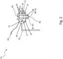
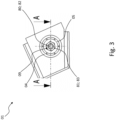
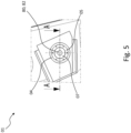
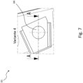
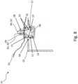
- Advantage is simple design, its self-adjustment and that it works with various fasteners such as bolt/nut and stud/nut combination ( 1 , 2 , 3 , 4 ) or with integrated bolt/nut ( figure 5 , 6 , 7 , 8 ).
- the device 01 fixes it to the body wall 03 in the flush position set during installation by means of a gauge in the installed state.
- the expansion sleeve 05 and the clamping cone 07 are initially arranged preferably in a floating manner on the lamp housing 02 and relative to one another. They are first braced against one another by means of one of the fastening elements of the fastening means 08 in a position in which they fix the lamp housing 02 in a position in the installation opening aligned by means of a jig during installation.
- the fastening system makes it possible to fix it at a variable distance from a rear body wall 03, for example, in the installed state, depending on its flushness, which is adjusted during installation using a gauge, depending on the manufacturing tolerances.
- An adjusting element 10 which is movably accommodated in a receptacle 04 and consists of a clamping cone 07 and an expanding sleeve 05, is pressed into one another when a component, in particular a vehicle light, is fastened by means of a fastening means 08 comprising a screw and/or nut, for example.
- a fastening means 08 comprising a screw and/or nut, for example.
- Grooves 11 on the expansion sleeve 05 and teeth 12 on the mount 04 ensure a positive connection when the expansion sleeve 05 is widened and the clamping cone 07 and the expansion sleeve 05 are squeezed together guaranteed for installation.
- the setting element 10 is held in its pre-assembly position by latching lugs 14 .
- the expansion sleeve 05 is accommodated in the receptacle 04 in addition to its floating arrangement along the longitudinal axis 06 in the direction of a displacement axis running normal to the longitudinal axis 06, also floating on the vehicle lamp or on the vehicle.
- the expansion sleeve 05 expands under the action of the clamping cone 07 when the fastening means 08 is actuated to reduce the distance in the direction of an expansion axis which is normal to the longitudinal axis 06 and normal to the displacement axis.
- the expansion sleeve 05 then expands under the action of the clamping cone 07 when the fastening means 08 is actuated to reduce the distance in the direction of an expansion axis which is normal to the longitudinal axis 06 and normal to the displacement axis.
- the fastening means 08 can comprise two fastening elements 80, 81 which interact with one another, for example a threaded bolt 82 and a threaded nut 83, a smooth bolt and a clamping washer self-locking against withdrawal from the smooth bolt, similar to a cable tie, a serrated bolt and a catch acting against withdrawal from the serrated bolt.
- the fastening means preferably comprises a threaded bolt 82 and a threaded nut 83.
- the clamping cone 07 can include one of the fastening elements 80, 81, for example a threaded bolt 82 or a threaded nut 83, or be encompassed by one of the fastening elements 80, 81.
- FIG. 7 and 8 show an embodiment in which the clamping cone 07 includes a threaded bolt 82.
- the clamping cone 07 can be used as in 8 shown in one piece with the threaded bolt 82.
- the expansion sleeve 05 can have a corrugation formed, for example, by grooves 11 on the outside of the receptacle 04 on a counterpart, which ribbing inhibits the floating arrangement in the receptacle 04 when the expansion sleeve 05 expands and finally cancels it.
- a ribbing can be provided, for example also formed by grooves, which fixes the clamping cone 07 in the expansion sleeve 05 as soon as it expands the expansion sleeve 05, at least against a distance-enlarging retreat.
- the clamping cone 07 is preferably arranged captively in the expansion sleeve 05. This can be done by a conical part of an inner lateral surface of the expansion sleeve 05 that interacts with the clamping cone 07, delimited by means of an inner latching section comprising a latching lug 14, for example, which inner latching section protrudes so far into a receiving opening surrounded by the conical part that a clamping cone accommodated therein 07 cannot pass the resting section under their own power.
- the expansion sleeve 05 is preferably arranged captively in the receptacle 04 on a counterpart.
- the outer lateral surface of the expansion sleeve 05 preferably having a central lateral surface section in the form of a straight, general cylinder whose cylinder axis extends parallel to the longitudinal axis 06.
- the outer lateral surface of the expansion sleeve 05 has on both sides of the middle lateral surface section an outer locking section acting towards the middle lateral surface section, for example comprising a locking lug 13 in each case.
- the distance between the outer lateral surface and the longitudinal axis 06 is greater in at least one direction normal to the longitudinal axis 06 than in the middle lateral surface section.
- the two outer latching sections allow the expansion sleeve 05 to be arranged in a captive manner, floating in the direction of the longitudinal axis 06, in a cross-sectional dimension that corresponds to the cross-sectional dimensions of the central lateral surface segment normal to the longitudinal axis, for example through an opening in a vehicle light or in a similar manner corresponding opening in a body wall delimiting an installation opening for the vehicle light.
- the device 01 accordingly comprises, for example, a bolt, for example a threaded bolt 82, extending along a longitudinal axis 06, and a fastening element 81, for example a nut 83, which interacts with the bolt.
- a bolt for example a threaded bolt 82
- a fastening element 81 for example a nut 83
- Conceivable combinations of bolts and fastening elements interacting with this are, for example, threaded bolts and threaded nuts, smooth bolts and clamping disks self-locking against withdrawal from the smooth bolt, serrated bolt and notch acting against withdrawal from the serrated bolt, similar to a cable tie.
- the device 01 also includes a clamping cone 07 that is movably arranged along the longitudinal axis 06 of the bolt.
- the device 01 comprises, for example, a hollow-cylindrical expansion sleeve 05 with a first end of the expansion sleeve 05, referred to for short as the closed end, from a base, for example with a central opening for the passage of the bolt that may be provided, which is limited in the shape of a section of a cone, of its inner lateral surface.
- the section-shaped part of the inner lateral surface of the expansion sleeve 05 correlates with the outer shape of the clamping cone 07 in such a way that it can be accommodated free of a deformation of the expansion sleeve 05 at least in the widest section of the section-shaped part.
- the expansion sleeve 05 Opposite the closed or first end, the expansion sleeve 05 has a second end, referred to as the open end for short. Both the hollow-cylindrical axis of the hollow-cylindrical expansion sleeve 05 and the solder of the part in the shape of a cone section extend from the first end to the opposite, second end of the expansion sleeve 05 along the longitudinal axis 06 of the bolt.
- the longitudinal axis 06 is normal to a surface spanned by an edge of the central opening in the floor.
- the part of the inner lateral surface of the expansion sleeve 05 in the shape of a cone section comprises at least one section whose inner dimension, referred to as the inner diameter for short, tapers conically in at least one direction normal to the longitudinal axis 06 from the open end of the expansion sleeve 05 to the closed end.
- the section-shaped part is preferably delimited by an inner latching section, in which the distance between the inner lateral surface and the longitudinal axis 06 is smaller in at least one direction normal to the longitudinal axis 06 than on the side in the section-shaped section facing the open end.
- the inner latching section allows the clamping cone 07 to be mounted in the expansion sleeve 05 so that it cannot be lost and is floating in the direction of the longitudinal axis 06.
- the outer lateral surface of the expansion sleeve 05 preferably has a central lateral surface section in the form of a straight, general cylinder whose cylinder axis extends parallel to the longitudinal axis 06. Viewed in both directions along the longitudinal axis 06, the outer lateral surface of the expansion sleeve 05 has on both sides of the middle lateral surface section an outer latching section acting towards the middle lateral surface section. In the outer latching sections, the distance between the outer lateral surface and the longitudinal axis 06 is greater in at least one direction normal to the longitudinal axis 06 than in the middle lateral surface section.
- the two outer latching sections permit a captive arrangement of the expansion sleeve 05, floating in the direction of the longitudinal axis 06 in the unexpanded state of the expansion sleeve 05, in a cross-sectional dimension that corresponds to the cross-sectional dimensions of the central lateral surface section normal to the longitudinal axis 06, for example through an opening in a vehicle light or in a corresponding opening in a body wall 03 delimiting an installation opening for the vehicle lamp.
- the clamping cone 07 can have a central opening for the passage of a fastening element 80 embodied, for example, as a bolt, preferably as a threaded bolt 82 .
- the clamping cone 07 can be connected to the bolt and initially arranged in a floating manner along the longitudinal axis of the bolt ( 7 , 8 ).
- the device forms a unit that is particularly easy to handle, since the clamping cone 07 is arranged captively together with the bolt in the expansion sleeve 05 and the expansion sleeve 05 with the clamping cone 07 it captively accommodates on the lamp or vehicle side initially until it is precisely aligned of the vehicle light relative to the vehicle is captively held floating in the direction of the longitudinal axis 06.
- a vehicle lamp which comprises a device 01 as described above for its at least partial attachment to a vehicle.
- the invention therefore also encompasses a vehicle light with at least one device 01 arranged on it for its at least partial attachment to a vehicle, for example to a body wall 03 delimiting an installation opening.
- the vehicle light has a light interior that is completely or partially enclosed by a light housing 02 and a lens and at least one light source that is at least partially housed therein and includes at least one light source for at least one light function.
- the vehicle light particularly preferably includes the receptacle 04 for the expansion sleeve 05.
- the receptacle 04 is advantageously arranged on the lamp housing 02 .
- the device 01 of the vehicle light comprises an expansion sleeve 05, a clamping cone 07 accommodated in the expansion sleeve 05 so that it can move along a longitudinal axis 06 while expanding the latter, and a fastening means 08 that interacts with the clamping cone 07.
- the expansion sleeve 05 is preferably arranged floating at least along the longitudinal axis 06 on the vehicle lamp, preferably its lamp housing 02.
- the clamping cone 07 is movably accommodated in the expansion sleeve 05 along the longitudinal axis 06 while expanding the expansion sleeve 05 and initially floats together with this along the longitudinal axis 06 on the vehicle lamp—primarily its lamp housing 02.
- the interaction of the fastening means 08 and the clamping cone 07 increases or decreases the distance between a fastening point 09, to which the fastening means 08 is preferably fixed on the vehicle side, and the clamping cone 07.
- the expansion sleeve 05 comes into contact with the vehicle - primarily a body wall 03 delimiting an installation opening for the vehicle light.
- only the clamping cone 07 can be moved along the longitudinal axis 06 by further actuating the fastening means 08 to reduce the distance while expanding the expansion sleeve 05. so that finally the fastening means 08 fixes the device 01 on the vehicle while being immovably fixed to the vehicle light by expanding the expansion sleeve 05 in a once assumed position along the longitudinal axis 06.
- the interaction of the fastening means 08 and the clamping cone 07 provides that an actuation of the fastening means 08 has a variable distance to the position of the clamping cone 07 along the longitudinal axis 06 compared to the fastening means 08 or its fastening point 09 on the counterpart of the vehicle lamp.
- the expansion sleeve 05 is also arranged floating on the vehicle light in addition to its floating arrangement in the unexpanded state along the longitudinal axis 06 in the direction of a displacement axis running normal to the longitudinal axis 06 .
- the expansion sleeve 05 expands under the action of the clamping cone 07 when the fastening means 08 is actuated to reduce the distance in the direction of an expansion axis which is normal to the longitudinal axis 06 and normal to the displacement axis.
- the invention can be implemented using a device 01 described above and/or a vehicle light also described above by a method for at least partially attaching a vehicle light to a vehicle, primarily in an installation opening, with the vehicle light and vehicle each having a form counterparts to each other.
- a first method step I the method provides that an above-described device 01 for at least partially fastening a vehicle light to a vehicle with its expansion sleeve 05 and with the clamping cone 07 accommodated by this, initially at least along the longitudinal axis 06, and then also in the direction of a normal to the longitudinal axis 06 running displacement axis, is arranged floating on a counterpart, corresponding to the vehicle lamp or on the vehicle.
- a second method step II following the first method step I the method provides that the fastening means 08 is attached to the vehicle forming the other counterpart to the vehicle lamp or to the vehicle lamp forming the other counterpart to the vehicle while limiting its free mobility at least in the direction of one counterpart is arranged towards.
- the location where the fastening means 08 is fixed while limiting its free mobility at least in the direction of one counterpart is referred to as the fastening point 09 from now on.
- a third step III following the second step II the method provides that the vehicle light, for example, using a this jig, which is aligned for example in an installation opening on the vehicle, is arranged in the exact location and position opposite the vehicle.
- a fourth method step IV following the third method step III the method provides that the fastening means 08 is connected to the clamping cone 07 and thereby reduces the distance in the direction of the longitudinal axis to the distance between the fastening point 09 of the fastening means 08 on the vehicle and the clamping cone 07 actuation of the fastener 08 first causes the expansion sleeve 05, which is initially arranged floating along the longitudinal axis 06 on one counterpart, for example on the vehicle light, to rest against the other counterpart, for example on the vehicle, for example on its body wall 03 delimiting the installation opening provided for accommodating the vehicle light is, then by further distance-reducing actuation of the fastening means 08, the clamping cone 07 now expands the expansion sleeve 05 without further displacement of the expansion sleeve 05, whereby the formerly floating recorded on a counterpart Sprei z sleeve 05 is fixed on one counterpart in its relative position now resting on the other counterpart.
- the method therefore initially provides for an initially floating arrangement of at least one device 01 for at least partially fastening a vehicle lamp in a receptacle on a vehicle on the vehicle lamp or on the vehicle.
- the device 01 comprises an expansion sleeve 05 and a clamping cone 07 accommodated in the expansion sleeve 05 so that it can move along a longitudinal axis 06 while expanding the latter, and a fastening means 08 that interacts with the clamping cone 07.
- the device 01 with its expansion sleeve 05 and with the clamping cone 07 received by it, is arranged floating on the vehicle lamp in the unexpanded state, initially at least along the longitudinal axis 06 and then also in the direction of a displacement axis running normal to the longitudinal axis 06.
- Fastening element 08 is arranged at a fastening point 09 on the vehicle side, for example by passing it through a fastening opening forming fastening point 09, on a body wall 03 delimiting an installation opening provided on the vehicle side for installing the vehicle light, at least while limiting its free mobility in the direction of the vehicle light.
- An example of this is the backward passage of a screw through a corresponding fastening opening, the threaded section of which extends towards the vehicle lamp and the head of which prevents the screw from being able to be pulled through the fastening opening towards the vehicle lamp.
- the vehicle lamp is then arranged on the vehicle using a jig that aligns it precisely in position and position, for example in an installation opening on the vehicle.
- the fastening means 08 is then brought into connection with the clamping cone and by actuating the fastening means 08 in the direction of the longitudinal axis 06, reducing the distance between the fastening point 09 of the fastening means 08 on the vehicle and the clamping cone 07, first floating along the longitudinal axis on the vehicle light arranged expansion sleeve 05 to rest on the vehicle, for example brought to its body wall 03 delimiting the installation opening provided for receiving the vehicle light.
- the expansion sleeve 05 is also arranged in a floating manner on the vehicle light in the direction of a displacement axis running normal to the longitudinal axis 06, so at the same time there is an alignment along the displacement axis, at the end of which alignment the device 01 is positioned in such a way that the longitudinal axis 06 is along the shortest Distance between attachment point 09 and the floating arrangement of the expansion sleeve 05 extends to the vehicle light.
- the clamping cone 07 is now brought closer to the attachment point 09 without further displacement of the expansion sleeve 05 by further actuation of the fastening means 08 to reduce the distance.
- the expansion sleeve 05 expands.
- the relative position of the expansion sleeve 05 on the vehicle light is determined by expanding the expansion sleeve 05 by the clamping cone 07 that is moved relative to it.
- the previously floating arrangement of the expansion sleeve 05 on the vehicle light is repealed. Due to the widening of the expansion sleeve 05, it is arranged in a stationary and immovable manner on the vehicle light.
- the gauge can be removed.
- the invention is achieved by means of a self-adjusting tolerance compensation and fastening element with an adjustment element 10 comprising an expanding element and an adjusting element 10 which is arranged movably along a longitudinal axis with expansion of the expanding cone 05 in this clamping cone 07 and which is located in a receptacle 04 at least along the longitudinal axis 06 is initially floating, can be realized.
- the receptacle 04 is provided on one of the components to be connected. If the tolerance compensation and fastening element is provided for fastening a vehicle light to a vehicle, the receptacle can be provided on the vehicle light or on the vehicle.
- the adjustment element 10 is fixed in the exact position in the receptacle when it is screwed on.
- the invention can be used commercially in particular in the field of manufacturing vehicle lights, in particular motor vehicle lights.
Description
Die Erfindung betrifft eine Vorrichtung gemäß dem Oberbegriff des Anspruchs 1 und eine hiermit ausgestattete Fahrzeugleuchte gemäß dem Oberbegriff des Anspruchs 9.The invention relates to a device according to the preamble of claim 1 and a vehicle light equipped therewith according to the preamble of claim 9.
Insbesondere beschäftigt sich die Erfindung mit einer Verbesserung der Einstellung und Befestigung von Fahrzeugleuchten an Fahrzeugen, allem voran in hierfür vorgesehenen Einbauöffnungen deren Karosserien beziehungsweise Karosserieteilen.In particular, the invention is concerned with improving the adjustment and fastening of vehicle lights on vehicles, above all in installation openings provided for this purpose in their bodies or body parts.
Mit zunehmender Fertigungspräzision in der Automobiltechnik steigen die Anforderungen an die Passgenauigkeit von Fahrzeugteilen. Dabei gilt das Hauptaugenmerk dem vom Endkunden unmittelbar erkennbaren äußeren Erscheinungsbild von Fahrzeugen, oft widergespiegelt durch das so genannte Spaltmaß, welches für Maßhaltigkeit, Abstand sowie Lage, beispielsweise hinsichtlich einer Verdrehlage, zweier oder mehrerer erkennbar unterschiedlicher, aneinander angrenzender Fahrzeugteile steht. Dabei ist ein möglichst gleichmäßiges und/oder kleines Spaltmaß einzuhalten, um die Qualitätsanforderungen einerseits hinsichtlich des Erscheinungsbilds und andererseits hinsichtlich einer möglichst strömungsgünstigen und "aus einem Guss" erscheinenden Fahrzeugoberfläche bzw. -kontur zu erfüllen.With increasing production precision in automotive engineering, the demands on the fitting accuracy of vehicle parts are increasing. The main focus is on the external appearance of vehicles that is immediately recognizable by the end customer, often reflected by the so-called gap size, which stands for dimensional accuracy, distance and position, for example with regard to a twisted position, of two or more recognizable different, adjacent vehicle parts. A gap dimension that is as uniform and/or as small as possible must be maintained in order to meet the quality requirements on the one hand with regard to the appearance and on the other hand with regard to a vehicle surface or contour that is as streamlined as possible and appears “from a single source”.
Besonders augenfällig ist dies bei Fahrzeugleuchten im Allgemeinen und Fahrzeugheckleuchten im Speziellen, welche sich je nach Fahrzeugmodell teils nahtlos, teils mit möglichst präzise und gleichmäßig einzuhaltendem Spaltmaß bündig in die Oberfläche einer Karosserie beziehungsweise eines oder mehrerer Karosserieteile einfügen müssen.This is particularly evident in vehicle lights in general and vehicle rear lights in particular, which, depending on the vehicle model, have to be inserted into the surface of a body or one or more body parts, either seamlessly or with a gap that is as precise and even as possible.
Eine Fahrzeugleuchte umfasst im Wesentlichen einen von einem Leuchtengehäuse und einer Lichtscheibe ganz oder teilweise umschlossenen Leuchteninnenraum und mindestens ein darin vollständig oder teilweise beherbergtes, mindestens eine Lichtquelle umfassendes Leuchtmittel für wenigstens eine Lichtfunktion der Fahrzeugleuchte.A vehicle light essentially comprises a light interior that is completely or partially enclosed by a light housing and a lens and at least one illuminant for at least one lighting function of the vehicle light that is completely or partially housed therein and includes at least one light source.
Jede Fahrzeugleuchte erfüllt je nach Ausgestaltung eine oder mehrere Aufgaben bzw. Funktionen. Zur Erfüllung jeder Aufgabe bzw. Funktion ist eine Lichtfunktion der Fahrzeugleuchte vorgesehen. Lichtfunktionen sind beispielsweise bei einer Ausgestaltung als Scheinwerfer eine die Fahrbahn ausleuchtende Funktion, oder bei einer Ausgestaltung als Signalleuchte eine Signalfunktion, wie beispielsweise eine Wiederholblinklichtfunktion zur Fahrtrichtungsanzeige oder eine Bremslichtfunktion zur Anzeige einer Bremstätigkeit, oder z.B. einer Begrenzungslichtfunktion, wie etwa einer Rücklichtfunktion, zur Sicherstellung einer Sichtbarkeit des Fahrzeugs bei Tag und/oder Nacht, wie etwa bei einer Ausgestaltung als Heckleuchte oder Tagfahrleuchte.Depending on the design, each vehicle light fulfills one or more tasks or functions. A light function of the vehicle light is provided to fulfill each task or function. Light functions are, for example, a function that illuminates the roadway when configured as a headlight, or a signal function when configured as a signal light, such as a repeating flashing light function to indicate the direction of travel or a brake light function to indicate braking activity, or e.g. a parking light function, such as a rear light function, to ensure a Day and/or night visibility of the vehicle, such as when configured as a rear light or daytime running light.
Beispiele für Fahrzeugleuchten sind am Fahrzeugbug, an den Fahrzeugflanken und/oder an den Seitenspiegeln sowie am Fahrzeugheck angeordnete Blinkleuchten, Ausstiegsleuchten, beispielsweise zur Umfeldbeleuchtung, Begrenzungsleuchten, Bremsleuchten, Nebelleuchten, Rückfahrleuchten, sowie typischerweise hoch gesetzte dritte Bremsleuchten, so genannte Central, High-Mounted Braking Lights, Tagfahrleuchten, Scheinwerfer und auch als Abbiege- oder Kurvenlicht verwendete Nebelscheinwerfer, sowie Kombinationen hiervon.Examples of vehicle lights are turn signals arranged on the front of the vehicle, on the sides of the vehicle and/or on the side mirrors and on the rear of the vehicle, exit lights, for example for ambient lighting, side lights, brake lights, fog lights, reversing lights, and typically high-mounted third brake lights, so-called central, high-mounted Braking lights, daytime running lights, headlights and fog lights used as cornering lights, and combinations thereof.
Die Befestigung einer Fahrzeugleuchte am Fahrzeug ist üblicherweise zwischen ihrem Leuchtengehäuse und mindestens einer eine im Folgenden unabhängig von ihrer Ausgestaltung als Einbauöffnung bezeichneten, beispielsweise eine Aufnahmeausnehmung in Form einer Vertiefung oder einer Aufnahmeöffnung in Form eines Ausschnitts oder Lochs bildenden Aussparung für die Fahrzeugleuchte beispielsweise in der Karosserie oder in einem oder mehreren Karosserieteilen begrenzenden Karosseriewandung vorgesehen.The fastening of a vehicle lamp to the vehicle is usually between its lamp housing and at least one recess for the vehicle lamp, for example in the bodywork, which is referred to below as an installation opening regardless of its design, for example a receiving recess in the form of a depression or a receiving opening in the form of a cutout or hole or provided in one or more body parts delimiting body wall.
Die Befestigung erfolgt beispielsweise mittels einer oder mehrerer Befestigungsvorrichtungen mit jeweils mindestens einem leuchtenseitig vorgesehenen ersten Befestigungselement sowie mindestens einem karosserie- bzw. fahrzeugseitig in der Einbauöffnung vorgesehenen, mit dem mindestens einen ersten Befestigungselement korrespondierenden zweiten Befestigungselement.It is fastened, for example, by means of one or more fastening devices, each with at least one first fastening element provided on the light side and at least one second fastening element provided on the bodywork or vehicle side in the installation opening and corresponding to the at least one first fastening element.
Beispielsweise ist durch
Um zwischen dem Rand der Fahrzeugleuchte und dem Rand der Einbauöffnung über den Umfang einen innerhalb von Toleranzvorgaben konstant breiten Spalt zu bilden, gestaltet sich die Montage der Fahrzeugleuchte schwierig. Ebenso verhält es sich bei der Montage von beispielsweise innerhalb von Toleranzvorgaben zumindest teils spaltfrei und/oder nahtlos, teils mit möglichst präzise und gleichmäßig einzuhaltendem Spaltmaß bündig in die Karosserie bzw. die Karosserieteile einzufügenden Fahrzeugleuchten.In order to form a constantly wide gap over the circumference within tolerance specifications between the edge of the vehicle light and the edge of the installation opening, the installation of the vehicle light is difficult. The same applies to the assembly of vehicle lights to be inserted flush into the body or the body parts, for example within tolerance specifications, at least partly without a gap and/or seamlessly, partly with a gap that is to be maintained as precisely and evenly as possible.
Dabei wird die Einhaltung der Toleranzvorgaben beeinflusst durch innerhalb einer Gesamttoleranz einer Fahrzeugleuchte zulässige Oberflächenabweichungen zum Linienriß bzw. zur Hüllfläche der Fahrzeugleuchte und zulässige Umrissabweichungen zum Linienriss bzw. zur Hüllfläche der Fahrzeugleuchte. Die Gesamttoleranz einer Fahrzeugleuchte ergibt sich dabei aus den Toleranzen der Einzelbauteile, wie etwa der verwendeten Spritzgussbauteile, sowie aus den Toleranzen der Fertigungsprozesse, wie beispielsweise für die Verbindung zweier oder mehrerer Einzelbauteile einer Fahrzeugleuchte verwendete Schweißprozesse.Adherence to the tolerance specifications is influenced by permissible surface deviations within a total tolerance of a vehicle light from the line tear or the envelope surface of the vehicle light and permissible outline deviations from the line tear or the envelope surface of the vehicle light. The overall tolerance of a vehicle light results from the tolerances of the individual components, such as the injection molded components used, and from the tolerances of the manufacturing processes, such as welding processes used to connect two or more individual components of a vehicle light.
Eine gesamte Toleranzkette von der Herstellung bis zum Einbau einer Fahrzeugleuchte in eine Einbauöffnung umfasst damit zusätzlich zu den zur Gesamttoleranz angegebenen Einflussgrößen die zulässige Toleranz in Bezug auf Position und Lage beim Einbau der Fahrzeugleuchte in die Einbauöffnung.An entire chain of tolerances from manufacture to installation of a vehicle light in an installation opening thus includes, in addition to the influencing factors specified for the overall tolerance, the permissible tolerance with regard to the position and orientation when installing the vehicle light in the installation opening.
Im Folgenden wird diese Problematik deshalb zusammengefasst als "Erfüllung von Toleranzvorgaben" bezeichnet, unabhängig davon, ob es sich um eine Maßhaltung der Fahrzeugleuchte in deren Herstellungsprozess oder um die Einhaltung eines Spaltmaßes bei deren Montage handelt, oder wenn es sich dabei zumindest zum Teil um einen spaltfreien, nahtlosen Übergang beispielsweise von der Lichtscheibe einer Fahrzeugleuchte zu einem angrenzenden Karosserieteil oder einer Karosseriefläche oder eines sonstigen Bauteils oder einer sonstigen Oberfläche eines Fahrzeugs handelt.In the following, this problem is therefore summarized as "fulfillment of tolerance specifications", regardless of whether it is a matter of maintaining the dimensions of the vehicle light in its manufacturing process or maintaining a gap dimension during its assembly, or if this is at least partly a gap-free, seamless transition, for example, from the lens of a vehicle lamp to an adjacent body part or a body surface or another component or other surface of a vehicle.
Stand der Technik sind Bearbeitungsstationen in denen Befestigungselemente beispielsweise rückseitig am Leuchtengehäuse der Fahrzeugleuchte mechanisch nachgearbeitet werden, um Toleranzvorgaben erfüllen zu können.State of the art are processing stations in which fastening elements are mechanically reworked, for example on the back of the lamp housing of the vehicle lamp, in order to be able to meet tolerance specifications.
Ebenfalls bekannt sind Bohr-/Fräs-Bearbeitungsstationen, bei denen die Aufnahmepunkte für Befestigungselemente gesetzt oder Anschlagelemente nachbearbeitet werden.Drilling/milling processing stations are also known, in which the receiving points for fastening elements are set or stop elements are reworked.
Nachteilig an einer derartigen mechanischen Bearbeitung ist, dass dabei entstehende Späne als Verunreinigungen in den Leuchteninnenraum gelangen können.The disadvantage of such mechanical processing is that the resulting chips can get into the interior of the lamp as contaminants.
Ferner weist eine solche mechanische Bearbeitung den Nachteil einer Gefahr einer Beschädigung der Lichtscheibe der während einer solchen mechanischen Bearbeitung mit der Lichtscheibe nach unten liegenden Fahrzeugleuchte auf.Furthermore, such a mechanical processing has the disadvantage of a risk of damage to the lens of the vehicle lamp lying with the lens down during such mechanical processing.
Diese mechanische Bearbeitung ist außerdem nicht geeignet, die in Zukunft immer enger werdenden Toleranzvorgaben prozesssicher erfüllen zu können.This mechanical processing is also not suitable for being able to reliably meet the tolerance specifications, which will become ever tighter in the future.
Um diesen Nachteil zu beheben, ist ebenfalls durch
Durch
Durch
Um die Montage von Fahrzeugleuchten mit mehrteiligen, verstellbaren ersten Befestigungselementen zu vereinfachen ist durch
Durch
Damit einerseits zwischen dem Rand der Lichtscheibe und einer die Einbauöffnung umgebenden Wandung ein konstant breiter Spalt gebildet wird, und damit andererseits die durch die Lichtscheibe gebildete Fläche eine die Einbauöffnung umgebende Oberfläche der Karosserie bündig fortführt und/oder einer durch den Rand der Einbauöffnung vorgegebenen Kontur bündig folgt, gestaltet sich die Montage der Fahrzeugleuchte schwierig.So that, on the one hand, a constantly wide gap is formed between the edge of the lens and a wall surrounding the installation opening, and so that, on the other hand, the surface formed by the lens continues flush with a surface of the body surrounding the installation opening and/or flush with a contour predetermined by the edge of the installation opening follows, the assembly of the vehicle lamp is difficult.
Durch
Eine nachträgliche Einstellung unter Veränderung der axialen Position des Gewindebolzens ist hierbei nicht mehr möglich.Subsequent adjustment by changing the axial position of the threaded bolt is no longer possible.
Um eine solche nachträgliche Einstellung zu ermöglichen, ist bekannt, den Gewindebolzen als eine Hohlschraube mit Innen- und Außengewinde auszuführen, die mit ihrem Innengewinde auf einen in seiner Lage und Position am Leuchtengehäuse festgelegten Gewindebolzen aufgeschraubt ist. Zwischen dem Innengewinde der Hohlschraube und dem Gewindebolzen ist ein Klemmteil aus Kunststoff, beispielsweise Nylon, angeordnet. Beispielsweise kann das Klemmteil wie bei einer selbstsichernden Mutter ringförmig koaxial zum Innengewinde an der Hohlschraube angeordnet sein, oder wie bei einer entsprechenden selbstsichernden Schraube in einer sich entlang der Längsachse des Gewindebolzens erstreckenden, in das Außengewinde des Gewindebolzens eingelassenen Nut angeordnet sein.In order to enable such a subsequent adjustment, it is known to design the threaded bolt as a hollow screw with an internal and external thread, which is screwed with its internal thread onto a threaded bolt fixed in its position and position on the lamp housing. A clamping part made of plastic, for example nylon, is arranged between the internal thread of the hollow screw and the threaded bolt. For example, like a self-locking nut, the clamping part can be arranged in a ring coaxial to the internal thread on the banjo bolt, or like a corresponding self-locking screw can be arranged in a groove that extends along the longitudinal axis of the threaded bolt and is embedded in the external thread of the threaded bolt.
Nachteilig hieran ist eine mangelnde Festlegung der Hohlschraube gegenüber dem Gewindebolzen durch das Klemmteil, wodurch es zu einer unbeabsichtigten Verstellung der Hohlschraube kommt, wenn auf diese beispielsweise von der Rückseite der Karosserie her eine Mutter mit einem zur Befestigung der Fahrzeugleuchte in der Einbauöffnung vorgesehenen Drehmoment aufgeschraubt wird.The disadvantage here is that the clamping part does not fix the banjo bolt in relation to the threaded bolt, which leads to an unintentional displacement of the banjo bolt if, for example, a nut is screwed onto it from the rear of the body with a torque provided for fastening the vehicle light in the installation opening .
Durch
Durch
Durch
Die Einstellung erfolgt dabei vor dem Einbau der Leuchte in die Einbauöffnung.The setting is made before installing the light in the installation opening.
Durch
Durch
Durch
Durch
Zusammengefasst sind die bekannten Befestigungsvorrichtungen im Hinblick auf eine Verbesserung der Einhaltung eines Spaltmaßes sehr montage- und/oder zeitaufwändig und durch die Verwendung einer Vielzahl von miteinander zusammenwirkender, einzeln vorzuhaltender und bei der Montage zusammenzuführender sowie zu beschaffender Bauteile sehr kostspielig.In summary, the known fastening devices are very assembly and/or time-consuming with regard to improving compliance with a gap dimension and are very expensive due to the use of a large number of interacting components that have to be kept available individually and brought together during assembly.
Ein generelles Ziel bei der Entwicklung von in einer Serienfertigung in Einbauöffnungen von Karosserien von Fahrzeugen zu montierender Fahrzeugleuchten ist die Verringerung der Kosten.A general goal in the development of vehicle lights to be mounted in installation openings of vehicle bodies in a series production is the reduction of costs.
Einen nicht unerheblichen Kostenbeitrag stellen die Montagekosten dar, welche es beispielsweise durch einen hohen Vorfertigungsgrad, eine geringe Anzahl von Bauteilen, mit denen während der Montage umgegangen werden muss, einhergehend mit einem sich kostensenkend auswirkenden geringen Zeitaufwand zur Montage, zu senken gilt.The assembly costs represent a not inconsiderable contribution to costs, which should be reduced, for example, through a high degree of prefabrication, a small number of components that have to be handled during assembly, together with a cost-reducing effect of a small amount of time required for assembly.
Dies kann erreicht werden beispielsweise durch eine Einsparung der Anzahl der vorzunehmenden einzelnen Handlungen während der Montage, wodurch es zu weniger Fehlmontagen kommt, was die Gesamtkosten senkt, sowie durch Befestigungsvorrichtungen, die verliersicher fahrzeug- und/oder leuchtenseitig vormontiert werden können und die ohne Nachjustieren eine positionsgenaue, wenigstens teilweise Befestigung einer Fahrzeugleuchte am Fahrzeug gestatten.This can be achieved, for example, by reducing the number of individual actions to be performed during assembly, resulting in fewer incorrect assemblies, which lowers the overall costs, and by Fastening devices that can be pre-assembled on the vehicle and/or lamp side in a captive manner and that allow a vehicle lamp to be fastened to the vehicle in a position-accurate, at least partial manner without readjustment.
Eine Aufgabe der Erfindung ist die Schaffung einer positionsgenauen Befestigung von Fahrzeugleuchten an Fahrzeugen.One object of the invention is to create a position-accurate attachment of vehicle lights to vehicles.
Insbesondere ist es eine Aufgabe der Erfindung eine Vorrichtung zur wenigstens teilweisen Befestigung von Fahrzeugleuchten an Fahrzeugen sowie eine mit einer entsprechenden Vorrichtung ausgestattete Fahrzeugleuchte zu entwickeln, welche die Erfüllung von Toleranzvorgaben mit einfachen und kostengünstigen Mitteln sicherstellen.In particular, it is an object of the invention to develop a device for at least partially fastening vehicle lights to vehicles and a vehicle light equipped with a corresponding device, which ensure compliance with tolerance specifications with simple and inexpensive means.
Die Aufgabe wird jeweils durch die Merkmale der unabhängigen Ansprüche gelöst. Vorteilhafte Ausführungsformen sind in den Ansprüchen, den Zeichnungen sowie in der nachfolgenden Beschreibung, einschließlich der zu den Zeichnungen zugehörigen, wiedergegeben.The object is solved in each case by the features of the independent claims. Advantageous embodiments are reproduced in the claims, the drawings and in the following description, including those associated with the drawings.
Ein erster Gegenstand der Erfindung betrifft demnach eine Vorrichtung zur wenigstens teilweisen Befestigung einer Fahrzeugleuchte an einem Fahrzeug, insbesondere einer eine Einbauöffnung begrenzenden Karosseriewandung.A first subject matter of the invention therefore relates to a device for at least partially fastening a vehicle lamp to a vehicle, in particular to a body wall delimiting an installation opening.
Die Vorrichtung umfasst eine Spreizhülse, einen unter Aufweitung der Spreizhülse entlang einer Längsachse beweglich in der Spreizhülse aufgenommen Spannkonus, und ein auf eine Position des Spannkonus entlang der Längsachse zu ihm abstandsveränderlich wirkendes Befestigungsmittel.The device comprises an expansion sleeve, a clamping cone accommodated in the expansion sleeve so that it can be moved along a longitudinal axis while the expansion sleeve expands, and a fastening means that acts on a position of the clamping cone along the longitudinal axis to change the distance to it.
Die Spreizhülse ist in unaufgeweitetem Zustand zumindest entlang der Längsachse schwimmend an der Fahrzeugleuchte - vorzugsweise deren Leuchtengehäuse - oder am Fahrzeug - vorzugsweise einer eine Einbauöffnung für die Fahrzeugleuchte an der Karosserie des Fahrzeugs begrenzenden Karosseriewandung - angeordnet.The expansion sleeve is in the unexpanded state at least along the longitudinal axis floating on the vehicle lamp - preferably its lamp housing - or on the vehicle - preferably a body wall delimiting an installation opening for the vehicle lamp on the body of the vehicle.
Die Spreizhülse wird durch abstandsverringernde Betätigung des Befestigungsmittels zunächst am Gegenpart zu ihrer schwimmenden Anordnung entlang der Längsachse zum Anliegen gebracht, also am Fahrzeug bei schwimmender Anordnung an der Fahrzeugleuchte und an der Fahrzeugleuchte bei schwimmender Anordnung am Fahrzeug.The expansion sleeve is first brought to bear on the counterpart to its floating arrangement along the longitudinal axis by actuating the fastening means to reduce the distance, ie on the vehicle with a floating arrangement on the vehicle lamp and on the vehicle lamp with a floating arrangement on the vehicle.
Die Spreizhülse ist beziehungsweise wird in durch weitere abstandsverringernde Betätigung des Befestigungsmittels erhaltenem aufgeweitetem Zustand in ihrer in unaufgeweitetem Zustand beziehungsweise vormals schwimmenden Anordnung unbeweglich festgelegt.The expansion sleeve is or is fixed immovably in the expanded state obtained by further distance-reducing actuation of the fastening means in its unexpanded state or previously floating arrangement.
Zusätzlich ist die Spreizhülse zu ihrer schwimmenden Anordnung in unaufgeweitetem Zustand entlang der Längsachse in Richtung einer normal zur Längsachse verlaufenden Verschiebeachse ebenfalls schwimmend an der Fahrzeugleuchte oder am Fahrzeug angeordnet. In diesem Fall weitet sich die Spreizhülse unter Einwirkung des Spannkonus bei abstandsverringernder Betätigung des Befestigungsmittels in Richtung einer sowohl normal auf der Längsachse, als auch normal auf der Verschiebeachse aufstehenden Ausdehnungsachse.In addition, for its floating arrangement in the unexpanded state along the longitudinal axis in the direction of a displacement axis running normal to the longitudinal axis, the expansion sleeve is also arranged floating on the vehicle lamp or on the vehicle. In this case, the expansion sleeve expands under the action of the clamping cone when the fastening means is actuated to reduce the distance in the direction of an expansion axis which is normal to the longitudinal axis and normal to the displacement axis.
Das Befestigungsmittel kann zwei miteinander zusammenwirkende Befestigungselemente umfassen, beispielsweise einen Gewindebolzen und eine Gewindemutter, einen Glattbolzen und eine gegen Abzug vom Glattbolzen selbsthemmende Klemmscheibe, ähnlich einem Kabelbinder einen Riffelbolzen und eine gegen Abzug vom Riffelbolzen wirkende Raste.The fastening means can comprise two mutually interacting fastening elements, for example a threaded bolt and a threaded nut, a smooth bolt and a clamping disk self-locking against being pulled off the smooth bolt, similar to a cable tie, a serrated bolt and a catch acting against being pulled off the serrated bolt.
Der Spannkonus kann eines der Befestigungselemente umfassen, beispielsweise einen Gewindebolzen oder eine Gewindemutter.The clamping cone can include one of the fastening elements, for example a threaded bolt or a threaded nut.
Bevorzugt weist die Spreizhülse außen eine Riffelung auf, welche bei deren Aufweitung die schwimmende Lagerung hemmt und schließlich aufhebt.Preferably, the expansion sleeve has a corrugation on the outside, which inhibits the floating bearing when it is expanded and finally eliminates it.
Zwischen Spreizhülse und Spannkonus kann alternativ oder zusätzlich eine Riffelung vorgesehen sein, welche den Spannkonus, sobald dieser die Spreizhülse aufweitet, in der Spreizhülse festsetzt.Alternatively or additionally, a corrugation can be provided between the expansion sleeve and the clamping cone, which ribbing fixes the clamping cone in the expansion sleeve as soon as it expands the expansion sleeve.
Besonders bevorzugt ist der Spannkonus verliersicher in der Spreizhülse angeordnet. Dies kann durch eine vermittels eines inneren Rastabschnitt begrenzte konusförmige Partie einer mit dem Spannkonus zusammenwirkenden inneren Mantelfläche der Spreizhülse vorgenommen sein, welcher innere Rastabschnitt so weit in eine von der konusförmigen Partie umgebene Aufnahmeöffnung ragt, dass ein hierin aufgenommener Spannkonus den Rastabschnitt nicht aus eigener Kraft passieren kann.The clamping cone is particularly preferably arranged captively in the expansion sleeve. This can be limited by means of an inner locking section conical portion of a cooperating with the clamping cone inner lateral surface of the expansion sleeve can be made, which inner latching section protrudes so far into a receiving opening surrounded by the conical part that a clamping cone accommodated therein cannot pass through the latching section under its own power.
Die Vorrichtung umfasst demnach beispielsweise einen sich entlang einer Längsachse erstreckenden Bolzen, beispielsweise einem Gewindebolzen, und ein mit dem Bolzen zusammenwirkendes Befestigungselement, beispielsweise einer Mutter.Accordingly, the device comprises, for example, a bolt extending along a longitudinal axis, for example a threaded bolt, and a fastening element, for example a nut, which interacts with the bolt.
Denkbare Kombinationen von Bolzen und mit diesem zusammenwirkendem Befestigungsmittel sind beispielsweise Gewindebolzen und Gewindemutter, Glattbolzen und gegen Abzug vom Glattbolzen selbsthemmende Klemmscheibe, Riffelbolzen und gegen Abzug vom Riffelbolzen wirkende Raste, ähnlich einem Kabelbinder.Conceivable combinations of bolts and fastening means interacting with them are, for example, threaded bolts and threaded nuts, smooth bolts and clamping disks self-locking against withdrawal from the smooth bolt, serrated bolt and notch acting against withdrawal from the serrated bolt, similar to a cable tie.
Die Vorrichtung umfasst außerdem einen entlang der Längsachse des Bolzens beweglich angeordneten Spannkonus.The device also includes a clamping cone arranged to be movable along the longitudinal axis of the bolt.
Darüber hinaus umfasst die Vorrichtung eine beispielsweise hohlzylinderförmige Spreizhülse mit einer bevorzugt zu einem kurz als geschlossenes Ende bezeichneten ersten Ende der Spreizhülse hin von einem Boden beispielsweise mit einer zentralen Öffnung zur Durchführung des gegebenenfalls vorgesehenen Bolzens begrenzten kegelabschnittförmigen Partie ihrer inneren Mantelfläche. Die kegelabschnittförmige Partie der inneren Mantelfläche der Spreizhülse korrelliert mit der äußeren Gestalt des Spannkonus dahingehend, dass dieser zumindest im weitesten Abschnitt der kegelabschnittförmigen Partie frei von einer Verformung der Spreizhülse aufgenommen werden kann.In addition, the device comprises, for example, a hollow-cylindrical expansion sleeve with a first end of the expansion sleeve, preferably referred to as the closed end, having a conical portion of its inner lateral surface delimited by a base, for example with a central opening for passing through the bolt that may be provided. The part of the cone section of the inner lateral surface of the expansion sleeve correlates with the outer shape of the clamping cone in such a way that it can be accommodated free of a deformation of the expansion sleeve at least in the widest section of the part in the form of a cone section.
Gegenüberliegend dem geschlossenen beziehungsweise ersten Ende weist die Spreizhülse ein kurz als offenes Ende bezeichnetes zweites Ende auf. Sowohl die Hohlzylinderachse der hohlzylinderförmigen Spreizhülse, als auch das Lot der kegelabschnittförmigen Partie erstrecken sich vom ersten Ende zum gegenüberliegenden zweiten Ende der Spreizhülse entlang der Längsachse des Bolzens. Die Längsachse steht normal auf einer von einem Rand der zentralen Öffnung im Boden aufgespannten Fläche auf. Die kegelabschnittförmige Partie der inneren Mantelfläche der Spreizhülse umfasst wenigstens einen Abschnitt, dessen kurz als Innendurchmesser bezeichnete Innenabmessung sich in wenigstens einer Richtung normal zur Längsachse von dem offenen Ende der Spreizhülse hin zum geschlossenen Ende konusartig verjüngt.Opposite the closed or first end, the expansion sleeve has a second end, referred to as the open end for short. Both the hollow-cylindrical axis of the hollow-cylindrical expansion sleeve and the solder of the part in the shape of a cone section extend from the first end to the opposite, second end of the expansion sleeve along the longitudinal axis of the bolt. The longitudinal axis is normal to a surface spanned by an edge of the central opening in the floor. The part of the inner lateral surface of the expansion sleeve in the form of a cone section comprises at least one section, which is referred to as the inner diameter for short Inner dimension tapers in at least one direction normal to the longitudinal axis from the open end of the expansion sleeve towards the closed end.
Zum offenen Ende hin ist die kegelabschnittförmige Partie vorzugsweise durch einen inneren Rastabschnitt begrenzt, in dem der Abstand der inneren Mantelfläche zur Längsachse in wenigstens einer Richtung normal zur Längsachse kleiner ist, als auf der dem offenen Ende zugewandten Seite in der kegelabschnittförmigen Partie.Towards the open end, the part in the shape of a cone section is preferably delimited by an inner latching section, in which the distance between the inner lateral surface and the longitudinal axis is smaller in at least one direction normal to the longitudinal axis than on the side in the part in the form of a cone section that faces the open end.
Der innere Rastabschnitt erlaubt eine verliersichere, in Richtung der Längsachse schwimmende Lagerung des Spannkonus in der Spreizhülse.The inner latching section allows a captive mounting of the clamping cone in the expansion sleeve, floating in the direction of the longitudinal axis.
Die äußere Mantelfläche der Spreizhülse weist bevorzugt einen mittleren Mantelflächenabschnitt in Form eines geraden, allgemeinen Zylinders auf, dessen Zylinderachse sich parallel zur Längsachse erstreckt. In beiden Richtungen entlang der Längsachse gesehen weist die äußere Mantelfläche der Spreizhülse auf beiden Seiten des mittleren Mantelflächenabschnitts jeweils einen zum mittleren Mantelflächenabschnitt hin wirkenden äußeren Rastabschnitt auf. In den äußeren Rastabschnitten ist der Abstand der äußeren Mantelfläche zur Längsachse in wenigstens einer Richtung normal zur Längsachse größer, als im mittleren Mantelflächenabschnitt.The outer lateral surface of the expansion sleeve preferably has a central lateral surface section in the form of a straight, general cylinder whose cylinder axis extends parallel to the longitudinal axis. Viewed in both directions along the longitudinal axis, the outer lateral surface of the expansion sleeve has on both sides of the central lateral surface section an outer latching section acting towards the central lateral surface section. In the outer latching sections, the distance between the outer lateral surface and the longitudinal axis is greater in at least one direction normal to the longitudinal axis than in the middle lateral surface section.
Die beiden äußeren Rastabschnitte erlauben eine verliersichere, in Richtung der Längsachse schwimmende Lagerung der Spreizhülse in einer in ihren Querschnittsabmessungen mit den Querschnittsabmessungen des mittleren Mantelflächenabschnitts normal zur Längsachse korrespondierenden Öffnung einer Fahrzeugleuchte oder in einer entsprechend korrespondierenden Öffnung in einer eine Einbauöffnung für die Fahrzeugleuchte begrenzenden Karosseriewandung.The two outer latching sections allow the expansion sleeve to be mounted in a captive manner, floating in the direction of the longitudinal axis, in an opening of a vehicle lamp whose cross-sectional dimensions correspond to the cross-sectional dimensions of the central lateral surface section normal to the longitudinal axis, or in a correspondingly corresponding opening in a body wall delimiting an installation opening for the vehicle lamp.
Der Spannkonus kann eine zentrale Öffnung zur Durchführung eines beispielsweise als Bolzen ausgeführten Befestigungselements aufweisen.The clamping cone can have a central opening for the passage of a fastening element designed, for example, as a bolt.
Alternativ kann der Spannkonus mit dem Bolzen verbunden und mit diesem gemeinsam entlang der Längsachse des Bolzens zunächst schwimmend beweglich angeordnet sein. In diesem Fall bildet die Vorrichtung eine im Umgang besonders einfach handhabbare Einheit, da der Spannkonus gemeinsam mit dem Bolzen verliersicher in der Spreizhülse angeordnet ist und die Spreizhülse mit dem von ihr verliersicher aufgenommenen Spannkonus leuchten- oder fahrzeugseitig zunächst bis zur positionsgenauen Ausrichtung von Fahrzeugleuchte relativ zum Fahrzeug verliersicher in Richtung der Längsachse schwimmend gelagert ist.Alternatively, the clamping cone can be connected to the bolt and initially arranged in a floating manner together with it along the longitudinal axis of the bolt. In this case, the device forms a unit that is particularly easy to handle in handling, since the clamping cone is arranged captively together with the bolt in the expansion sleeve and the expansion sleeve with the clamping cone accommodated by it captively lights or vehicle side first up to precise position alignment of the vehicle light relative to the vehicle is captively mounted floating in the direction of the longitudinal axis.
Ein zweiter Gegenstand der Erfindung betrifft eine Fahrzeugleuchte mit mindestens einer an ihr angeordneten Vorrichtung zu deren wenigstens teilweisen Befestigung an einer eine Einbauöffnung begrenzenden Karosseriewandung, wobei:
- die Vorrichtung eine Spreizhülse, einen entlang einer Längsachse unter Aufweitung der Spreizhülse beweglich in dieser aufgenommenen Spannkonus, und ein mit dem Spannkonus zusammenwirkendes Befestigungsmittel umfasst,
- die Spreizhülse in unaufgeweitetem Zustand zumindest entlang der Längsachse schwimmend an der Fahrzeugleuchte, vorzugsweise deren Leuchtengehäuse angeordnet ist,
- der Spannkonus unter Aufweitung der Spreizhülse entlang der Längsachse beweglich in der Spreizhülse aufgenommen ist, und zunächst gemeinsam mit dieser entlang der Längsachse schwimmend an der Fahrzeugleuchte - vornehmlich deren Leuchtengehäuse - angeordnet ist,
- das Zusammenwirken des Befestigungsmittels und des Spannkonus je nach Betätigungsrichtung eine Vergrößerung oder eine Verkleinerung des Abstands zwischen dem Befestigungsmittel und dem Spannkonus bewirkt,
- mit zunehmender Verkleinerung des Abstands zwischen Befestigungsmittel und Spannkonus die Spreizhülse zur Anlage am Fahrzeug kommt - vornehmliche einer eine Einbauöffnung für die Fahrzeugleuchte begrenzenden Karosseriewandung - und schließlich nur noch der Spannkonus durch weitere Betätigung des Befestigungsmittels unter Aufweitung des Spreizhülse entlang der Längsachse beweglich ist, so dass schließlich das Befestigungsmittel die Vorrichtung am Fahrzeug unter unbeweglicher Festlegung an der Fahrzeugleuchte durch Aufweitung der Spreizhülse in einer einmal eingenommenen Position entlang der Längsachse festliegt.
- the device comprises an expansion sleeve, a clamping cone received in the expansion sleeve so that it can move along a longitudinal axis with expansion of the latter, and a fastening means which interacts with the clamping cone,
- the expansion sleeve in the unexpanded state is arranged floating at least along the longitudinal axis on the vehicle light, preferably its light housing,
- the clamping cone is accommodated in the expansion sleeve so that it can move along the longitudinal axis while the expansion sleeve expands, and is initially arranged floating on the vehicle lamp - primarily its lamp housing - together with this along the longitudinal axis,
- the interaction of the fastener and the clamping cone causes an increase or decrease in the distance between the fastener and the clamping cone, depending on the direction of actuation,
- as the distance between the fastening means and the clamping cone decreases, the expansion sleeve comes into contact with the vehicle - primarily a body wall delimiting an installation opening for the vehicle light - and finally only the clamping cone can be moved along the longitudinal axis by further actuation of the fastening means with expansion of the expansion sleeve, so that Finally, the fastening means fixes the device on the vehicle with immovable attachment to the vehicle light by expanding the expansion sleeve in a once assumed position along the longitudinal axis.
Mit anderen Worten sieht das Zusammenwirken von Befestigungsmittel und Spannkonus vor, dass sich eine Betätigung des Befestigungsmittels abstandsveränderlich auf die Position des Spannkonus entlang der Längsachse gegenüber dem Befestigungsmittel beziehungsweise dessen Befestigungspunkt am Gegenpart der Fahrzeugleuchte auswirkt.In other words, the interaction of fastening means and clamping cone provides that actuation of the fastening means has a variable distance effect on the position of the clamping cone along the longitudinal axis relative to the fastening means or its fastening point on the counterpart of the vehicle light.
Die Spreizhülse ist zusätzlich zu ihrer schwimmenden Anordnung in unaufgeweitetem Zustand entlang der Längsachse in Richtung einer normal zur Längsachse verlaufenden Verschiebeachse ebenfalls schwimmend an der Fahrzeugleuchte angeordnet. Die Spreizhülse weitet sich unter Einwirkung des Spannkonus bei abstandsverringernder Betätigung des Befestigungsmittels in Richtung einer sowohl normal auf der Längsachse, als auch normal auf der Verschiebeachse aufstehenden Ausdehnungsachse.In addition to its floating arrangement in the unexpanded state, the expansion sleeve is also arranged floating on the vehicle lamp along the longitudinal axis in the direction of a displacement axis running normal to the longitudinal axis. The expansion sleeve expands under the action of the clamping cone when the fastening means is actuated to reduce the distance in the direction of an expansion axis which is normal to the longitudinal axis and normal to the displacement axis.
Das Verfahren zur wenigstens teilweisen Befestigung einer Fahrzeugleuchte in einer Einbauöffnung sieht zuerst eine zunächst schwimmende Anordnung wenigstens einer Vorrichtung zur wenigstens teilweisen Befestigung einer Fahrzeugleuchte in einer Aufnahme wenigstens einer Vorrichtung zur wenigstens teilweisen Befestigung einer Fahrzeugleuchte an einem Fahrzeug an der Fahrzeugleuchte oder am Fahrzeug vor.The method for at least partially attaching a vehicle light in an installation opening firstly provides for an initially floating arrangement of at least one device for at least partially attaching a vehicle light in a receptacle of at least one device for at least partially attaching a vehicle light to a vehicle on the vehicle light or on the vehicle.
Im nachfolgenden wird nur noch Bezug genommen auf eine schwimmende Anordnung an der Fahrzeugleuchte, ohne dass dies eine Beschränkung dahingehend bildet, dass nicht auch eine schwimmende Anordnung am Fahrzeug, insbesondere an einer eine Einbauöffnung für eine Fahrzeugleuchte begrenzende Karosseriewandung zum selben gewünschten Ergebnis führen kann, es sei denn, es ist explizit etwas anderes erwähnt.In the following, reference is only made to a floating arrangement on the vehicle lamp, without this constituting a restriction to the effect that a floating arrangement on the vehicle, in particular on a body wall delimiting an installation opening for a vehicle lamp, cannot lead to the same desired result unless explicitly stated otherwise.
Die Vorrichtung umfasst eine Spreizhülse und einen entlang einer Längsachse unter Aufweitung der Spreizhülse beweglich in dieser aufgenommenen Spannkonus, und ein mit dem Spannkonus zusammenwirkendes Befestigungsmittel.The device comprises an expansion sleeve and a clamping cone received in the expansion sleeve so that it can move along a longitudinal axis with expansion of the latter, and a fastening means which interacts with the clamping cone.
Die Vorrichtung ist mit ihrer Spreizhülse und mit dem von dieser aufgenommenen Spannkonus zunächst zumindest entlang der Längsachse, zusätzlich gegebenenfalls in Richtung einer normal zur Längsachse verlaufenden Verschiebeachse, schwimmend an der Fahrzeugleuchte angeordnet.The device, with its expansion sleeve and with the clamping cone accommodated by it, is initially arranged floating on the vehicle light, at least along the longitudinal axis, optionally in addition in the direction of a displacement axis running normal to the longitudinal axis.
Das Befestigungsmittel wird an einem fahrzeugseitigen Befestigungspunkt beispielsweise unter Durchführung durch eine den Befestigungspunkt bildenden Befestigungsöffnung an einer eine zum Einbau der Fahrzeugleuchte fahrzeugseitig vorgesehene Einbauöffnung begrenzenden Karosseriewandung zumindest unter Begrenzung seiner freien Beweglichkeit in Richtung zur Fahrzeugleuchte hin angeordnet. Ein Beispiel hierfür ist die rückwärtige Durchführung einer Schraube durch eine entsprechende Befestigungsöffnung, wobei deren Gewindeabschnitt zur Fahrzeugleuchte hin reicht, und deren Kopf verhindert, dass die Schraube durch die Befestigungsöffnung zur Fahrzeugleuchte hin gezogen werden kann.The fastening means is attached to a vehicle-side fastening point, for example by being passed through a fastening opening forming the fastening point, on a body wall delimiting an installation opening provided on the vehicle side for installation of the vehicle lamp Arranged limiting its free movement in the direction of the vehicle light. An example of this is the backward passage of a screw through a corresponding fastening opening, the threaded section of which extends towards the vehicle lamp and the head of which prevents the screw from being able to be pulled through the fastening opening towards the vehicle lamp.
Anschließend wird die Fahrzeugleuchte unter Einsatz einer diese lage- und positionsgenau beispielsweise in einer Einbauöffnung am Fahrzeug ausrichtenden Lehre am Fahrzeug angeordnet.The vehicle lamp is then arranged on the vehicle using a jig that aligns it precisely in position and position, for example in an installation opening on the vehicle.
Dann wird das Befestigungsmittel mit dem Spannkonus in Verbindung gebracht und durch sich in Richtung der Längsachse abstandsverringernd auf den Abstand zwischen Befestigungspunkt des Befestigungsmittels am Fahrzeug und dem Spannkonus auswirkende Betätigung des Befestigungsmittels zuerst die zunächst entlang der Längsachse schwimmend an der Fahrzeugleuchte angeordnete Spreizhülse zur Anlage am Fahrzeug, beispielsweise an dessen die zur Aufnahme der Fahrzeugleuchte vorgesehene Einbauöffnung begrenzender Karosseriewandung gebracht.The fastening means is then connected to the clamping cone and, by actuating the fastening means in the direction of the longitudinal axis and reducing the distance between the fastening point of the fastening means on the vehicle and the clamping cone, first the expansion sleeve, which is initially arranged floating along the longitudinal axis on the vehicle light, for contact with the vehicle , brought, for example, to the body wall delimiting the installation opening provided for receiving the vehicle lamp.
Die Spreizhülse ist zusätzlich in Richtung einer normal zur Längsachse verlaufenden Verschiebeachse schwimmend an der Fahrzeugleuchte angeordnet, so findet hierbei zugleich eine Ausrichtung entlang der Verschiebeachse statt, am Ende welcher Ausrichtung die Vorrichtung derart positioniert ist, dass die Längsachse sich entlang der kürzesten Entfernung zwischen Befestigungspunkt und der schwimmenden Anordnung der Spreizhülse an der Fahrzeugleuchte erstreckt.The expansion sleeve is also arranged floating on the vehicle light in the direction of a displacement axis running normal to the longitudinal axis, so there is an alignment along the displacement axis at the same time, at the end of which alignment the device is positioned in such a way that the longitudinal axis is along the shortest distance between the attachment point and the floating arrangement of the expansion sleeve extends to the vehicle lamp.
Liegt die Spreizhülse schließlich am Fahrzeug an, so wird durch weitere abstandsverringernde Betätigung des Befestigungsmittels der Spannkonus nunmehr ohne weitere Verschiebung der Spreizhülse näher zum Befestigungspunkt verbracht. Hierbei findet eine Aufweitung der Spreizhülse statt. Hierbei erfolgt eine Festlegung der Relativposition der Spreizhülse an der Fahrzeugleuchte vermittels Aufweitung der Spreizhülse durch den relativ zu dieser bewegten Spannkonus.If the expansion sleeve finally rests on the vehicle, the clamping cone is now brought closer to the attachment point without further displacement of the expansion sleeve by further actuation of the fastening means to reduce the distance. Here, the expansion sleeve expands. Here, the relative position of the expansion sleeve on the vehicle lamp is determined by means of expansion of the expansion sleeve by the clamping cone moved relative to it.
Bei dieser Festlegung wird die vormals schwimmende Anordnung der Spreizhülse an der Fahrzeugleuchte aufgehoben. Durch die Aufweitung der Spreizhülse ist diese ortsfest und unbeweglich an der Fahrzeugleuchte angeordnet.With this definition, the formerly floating arrangement of the expansion sleeve on the vehicle light is repealed. Due to the widening of the expansion sleeve, it is arranged in a stationary and immovable manner on the vehicle light.
Ist die Fahrzeugleuchte hiernach lage- und positionsgenau am Fahrzeug festgelegt, kann die Lehre entfernt werden.If the vehicle light is then fixed in the exact position and position on the vehicle, the gauge can be removed.
Das Verfahren endet hiernach.The procedure ends here.
Es ist ersichtlich, dass die Erfindung durch ein selbst einstellendes Toleranzausgleichs- und Befestigungselement mit einem einen Spreiz- und einen entlang einer Längsachse unter Aufweitung des Spreizkonus in diesem beweglich angeordneten Spannkonus umfassenden Einstellelement, welches in einer Aufnahme zumindest entlang der Längsachse zunächst schwimmend gelagert ist, verwirklicht sein kann.It can be seen that the invention, by means of a self-adjusting tolerance compensation and fastening element with an adjusting element comprising an expanding element and an adjusting element arranged movably along a longitudinal axis with expansion of the expanding cone in this clamping cone, which is initially floatingly mounted in a receptacle at least along the longitudinal axis, can be realized.
Die Aufnahme ist an einem der miteinander zu verbindenden Bauteile vorgesehen. Ist das Toleranzausgleichs- und Befestigungselement zur Befestigung einer Fahrzeugleuchte an einem Fahrzeug vorgesehen, so kann die Aufnahme an der Fahrzeugleuchte oder am Fahrzeug vorgesehen sein.The receptacle is provided on one of the components to be connected. If the tolerance compensation and fastening element is provided for fastening a vehicle light to a vehicle, the receptacle can be provided on the vehicle light or on the vehicle.
Durch den Spreiz- und den Spannkonus wird das Einstellelement beim Anschrauben positionsgenau in der Aufnahme fixiert.Due to the expansion and the clamping cone, the adjustment element is fixed in the exact position in the mount when it is screwed on.
Vorteile gegenüber dem Stand der Technik ergeben sich durch eine einfache Ausführung, eine selbstständige Einstellung, sowie eine Verwendbarkeit in Verbindung mit Standard-Befestigungsmitteln, wie etwa mit Schrauben/Mutter und Stehbolzen/Mutter.Advantages over the prior art result from a simple design, independent adjustment, and usability in connection with standard fasteners, such as screws/nuts and studs/nuts.
Zusätzliche, über eine vollständige Lösung der gestellten Aufgabe unter Beseitigung der Nachteile des Standes der Technik hinausgehende Vorteile sind, dass kein Einstellen notwendig ist. Darüber hinaus kann auf Standard-Befestigungsmittel zur Verspannung des Spreiz- und einem Spannkonus zurückgegriffen werden. Funktioniert mit Schrauben und Muttern und angeformten Gewindebolzen, ist kostengünstig.Additional advantages that go beyond a complete solution of the task at hand while eliminating the disadvantages of the prior art are that no adjustment is necessary. In addition, standard fasteners can be used to brace the expansion cone and a clamping cone. Works with nuts and bolts and molded studs, is cost effective.
Die Vorrichtung kann einzelne oder eine Kombination der zuvor und/oder nachfolgend in Verbindung mit der Fahrzeugleuchte und/oder dem Verfahren beschriebene Merkmale aufweisen, ebenso wie das Verfahren einzelne oder eine Kombination mehrerer zuvor und/oder nachfolgend in Verbindung mit der Vorrichtung und/oder der Fahrzeugleuchte beschriebene Merkmale aufweisen und/oder verwirklichen kann. Darüber hinaus kann die Fahrzeugleuchte einzelne oder eine Kombination der zuvor und/oder nachfolgend in Verbindung mit der Vorrichtung und/oder dem Verfahren beschriebene Merkmale aufweisen.The device can have individual features or a combination of the features described above and/or below in connection with the vehicle light and/or the method, just like the method can have individual features or a combination of several features previously and/or below in connection with the device and/or the Have vehicle light features described and / or can implement. In addition, the vehicle lamp can have individual features or a combination of the features described above and/or below in connection with the device and/or the method.
Die Erfindung einschließlich deren über die vollständige Lösung der gestellten Aufgabe und/oder über die voran zu den einzelnen Merkmalen genannten Vorteile hinausgehende Vorteile gegenüber dem Stand der Technik wird nachfolgend anhand von in der Zeichnung dargestellter Ausführungsbeispiele näher erläutert. Die Größenverhältnisse der einzelnen Elemente zueinander in den Figuren entsprechen nicht immer den realen Größenverhältnissen, da einige Formen vereinfacht und andere Formen zur besseren Veranschaulichung vergrößert im Verhältnis zu anderen Elementen dargestellt sind. Für gleiche oder gleich wirkende Elemente der Erfindung werden identische Bezugszeichen verwendet. Ferner werden der Übersicht halber nur Bezugszeichen in den einzelnen Figuren dargestellt, die für die Beschreibung der jeweiligen Figur erforderlich sind. Die dargestellten Ausführungsformen stellen lediglich Beispiele dar, wie die Erfindung ausgestaltet sein kann und stellen keine abschließende Begrenzung dar. Es zeigen in schematischer Darstellung:
- Fig. 1
- ein erstes Ausführungsbeispiel einer Vorrichtung zur wenigstens teilweisen Befestigung einer Fahrzeugleuchte an einem Fahrzeug in einer Draufsicht.
- Fig. 2
- die Vorrichtung aus
Fig. 1 in einem Längsschnitt A - A. - Fig. 3
- ein zweites Ausführungsbeispiel einer Vorrichtung zur wenigstens teilweisen Befestigung einer Fahrzeugleuchte an einem Fahrzeug in einer Draufsicht.
- Fig. 4
- die Vorrichtung aus
Fig. 3 in einem Längsschnitt A - A. - Fig. 5
- ein drittes Ausführungsbeispiel einer Vorrichtung zur wenigstens teilweisen Befestigung einer Fahrzeugleuchte an einem Fahrzeug in einer Draufsicht.
- Fig. 6
- die Vorrichtung aus
Fig. 5 in einem Längsschnitt A - A. - Fig. 7
- ein viertes Ausführungsbeispiel einer Vorrichtung zur wenigstens teilweisen Befestigung einer Fahrzeugleuchte an einem Fahrzeug in einer Draufsicht.
- Fig. 8
- die Vorrichtung aus
Fig. 7 in einem Längsschnitt A - A. - Fig. 9
- ein Ablaufdiagramm eines Verfahrens zur wenigstens teilweisen Befestigung einer Fahrzeugleuchte an einem Fahrzeug.
- 1
- a first embodiment of a device for at least partially attaching a vehicle lamp to a vehicle in a plan view.
- 2
- the device off
1 in a longitudinal section A - A. - 3
- a second embodiment of a device for at least partially attaching a vehicle lamp to a vehicle in a top view.
- 4
- the device off
3 in a longitudinal section A - A. - figure 5
- a third exemplary embodiment of a device for at least partially fastening a vehicle lamp to a vehicle in a top view.
- 6
- the device off
figure 5 in a longitudinal section A - A. - 7
- a fourth exemplary embodiment of a device for at least partially fastening a vehicle lamp to a vehicle in a plan view.
- 8
- the device off
7 in a longitudinal section A - A. - 9
- a flow chart of a method for at least partially attaching a vehicle lamp to a vehicle.
Eine in
- eine in
einer Aufnahme 04 an einem der beiden durch Fahrzeugleuchte und Fahrzeug gebildeten Gegenparte anordbare und/oder angeordnete Spreizhülse 05, - einen unter Aufweitung der Spreizhülse 05 entlang einer Längsachse 06 beweglich in
der Spreizhülse 05aufgenommen Spannkonus 07, und - ein beispielsweise an
einem Befestigungspunkt 09 am verbleibenden, anderen Gegenpart festlegbares und durch dessen Betätigung auf eine Position desSpannkonus 07 entlang der Längsachse 06 zu ihm, nämlich dem Befestigungspunkt, abstandsveränderlich wirkendes Befestigungsmittel 08.
- an
expansion sleeve 05 which can be arranged and/or is arranged in areceptacle 04 on one of the two counterparts formed by the vehicle lamp and the vehicle, - a clamping
cone 07 accommodated in theexpansion sleeve 05 so that it can move along alongitudinal axis 06 while expanding theexpansion sleeve 05, and - a fastening means 08 that can be fixed, for example, at a
fastening point 09 on the remaining, other counterpart and, when it is actuated, to a position of the clampingcone 07 along thelongitudinal axis 06 relative to it, namely the fastening point, with a variable distance effect.
Die Spreizhülse 05 ist in unaufgeweitetem Zustand in der Aufnahme 04 zumindest in Richtung entlang der Längsachse 06 schwimmend anordbar und/oder aufgenommen. In aufgeweitetem Zustand ist sie in der Aufnahme 04 in ihrer dann eingenommenen Position entlang der Längsachse 06 festlegbar und/oder festgelegt. Durch abstandsverringernd auf die Position des Spannkonus 07 zu ihm, insbesondere auf den Abstand zwischen dem Spannkonus 07 und dem Befestigungspunkt 09 des Befestigungsmittels 09 am verbleibenden, anderen Gegenpart wirkende Betätigung des Befestigungsmittels zunächst die Spreizhülse 05 zur Anlage am anderen Gegenpart bringbar ist und/oder gebracht wird und anschließend der Spannkonus 07 die Spreizhülse 05 aufweitet.In the unexpanded state, the
Die Vorrichtung 01 umfasst demnach eine Spreizhülse 05, einen unter Aufweitung der Spreizhülse 05 entlang einer Längsachse 06 beweglich in der Spreizhülse 05 aufgenommen Spannkonus 07, und ein auf eine Position des Spannkonus 07 entlang der Längsachse 06 zu ihm abstandsveränderlich wirkendes Befestigungsmittel 08.The
Die Spreizhülse 05 ist in unaufgeweitetem Zustand zumindest entlang der Längsachse 06 schwimmend am einen Gegenpart, nämlich an der Fahrzeugleuchte - vorzugsweise deren Leuchtengehäuse 02 - oder am Fahrzeug - vorzugsweise einer eine Einbauöffnung für die Fahrzeugleuchte an der Karosserie des Fahrzeugs begrenzenden Karosseriewandung 03 - angeordnet.In the unexpanded state, the
Die Spreizhülse 05 wird durch abstandsverringernde Betätigung des Befestigungsmittels 08 zunächst am verbleibenden, anderen Gegenpart zu dem einen Gegenpart, an dem sie schwimmend angeordnet ist, entlang der Längsachse zum Anliegen gebracht, also am Fahrzeug bei schwimmender Anordnung an der Fahrzeugleuchte und an der Fahrzeugleuchte bei schwimmender Anordnung am Fahrzeug.By actuating the fastening means 08 to reduce the distance, the
Die Spreizhülse 05 ist beziehungsweise wird in durch weitere abstandsverringernde Betätigung des Befestigungsmittels 08 erhaltenem aufgeweitetem Zustand in ihrer in unaufgeweitetem Zustand beziehungsweise vormals schwimmenden Anordnung unbeweglich festgelegt.The
Die Vorrichtung 01 stellt zugleich einen Toleranzausgleich, als auch eine zuverlässige Befestigung einer Fahrzeugleuchte an einem Fahrzeug sicher.At the same time, the
Es ist ersichtlich, dass die Erfindung verwirklicht sein kann durch eine Vorrichtung 01, welche ein zunächst schwimmend aufgenommenes, die Spreizhülse 05 und den Spannkonus 07 umfassendes Einstellelement 10 umfasst, welches durch Betätigung eines mit dem Spannkonus 07 durch Veränderung dessen Abstands zu einem Befestigungspunkt 09 zusammenwirkenden, am Befestigungspunkt 09 festgelegten Befestigungsmittel 08 in einer Anlageposition unter Verlust seiner schwimmenden Anordnung fixiert wird.It can be seen that the invention can be implemented by a
Durch die Spreizhülse 05 und den Spannkonus 07 wird das Einstellelement 10 beim Anschrauben positionsgenau in der Aufnahme 04 fixiert. Vorteil ist eine einfache Ausführung, dessen selbstständige Einstellung und dass es mit verschiedenen Befestigungsmitteln funktioniert, wie etwa Schrauben/Mutter und Stehbolzen/Mutter Kombination (
Die Vorrichtung 01 legt beim Einbau einer Fahrzeugleuchte in eine Einbauöffnung diese an der Karosseriewandung 03 in deren während des Einbaus mittels einer Lehre eingestellter Bündigkeit in eingebautem Zustand fest.When a vehicle light is installed in an installation opening, the
Beispielsweise umfasst die Vorrichtung 01
- einen sich entlang der Längsachse 06 erstreckenden, beispielsweise karosserieseitig angeordneten Bolzen 82 als
ein erstes Befestigungselement 80 desBefestigungsmittels 08, - eine in einer beispielsweise durch eine eine normal
zu dem Bolzen 82 verlaufende Ebene aufspannenden Öffnung gebildeten Aufnahme 04am Leuchtengehäuse 02 einer Fahrzeugleuchte inRichtung der Längsachse 06 schwimmend gelagerten ersten hohlzylinderförmigen Spreizhülse 05, deren Hohlzylinderachse mit der Längsachse des Bolzens 82 übereinstimmt, und deren innere Mantelfläche eine deren Innendurchmesser konusförmig verjüngende Partie aufweist, sowie - einem zwischen der Spreizhülse 05
und dem Bolzen 82 angeordneten und inRichtung der Längsachse 06 schwimmend gegenüberdem Bolzen 82 gelagerten hohlzylinderförmigen Spannkonus 07, dessen Hohlzylinderachse ebenfalls mit der Längsachse 06 desBolzens 82 übereinstimmt, und dessen äußere Mantelfläche eine dessen Außendurchmesser entgegen der verjüngenden Partie der Spreizhülse 05 konusförmig erweiternde Partie aufweist, sowie - ein entlang der Längsachse 06 des
Bolzens 82 gegenüber diesem festlegbares zweites Befestigungselement 81 desBefestigungsmittels 08, beispielsweise eine Gewindemutter 83, ein Federspannring, Kabelbinderverrastung, etc.
- a
bolt 82 which extends along thelongitudinal axis 06 and is arranged, for example, on the bodywork as afirst fastening element 80 of the fastening means 08, - a first hollow-
cylindrical expansion sleeve 05, which is mounted floating in the direction of thelongitudinal axis 06 in areceptacle 04 on thelamp housing 02 of a vehicle lamp and is formed, for example, by an opening spanning a plane running normal to thebolt 82, whose hollow cylinder axis coincides with the longitudinal axis of thebolt 82, and whose inner lateral surface one whose inner diameter has a conically tapering section, and - a hollow-
cylindrical clamping cone 07 which is arranged between theexpansion sleeve 05 and thebolt 82 and is mounted floating in relation to thebolt 82 in the direction of thelongitudinal axis 06, the hollow-cylindrical axis of which also coincides with thelongitudinal axis 06 of thebolt 82, and the outer lateral surface of which has an outer diameter opposite to the tapering section of theExpansion sleeve 05 has a conically widening section, as well as - a
second fastening element 81 of fastening means 08 that can be fixed relative to bolt 82 alonglongitudinal axis 06, for example a threadednut 83, a spring clamping ring, cable tie catch, etc.
Die Spreizhülse 05 und der Spannkonus 07 sind zunächst schwimmend vorzugsweise am Leuchtengehäuse 02 und relativ zueinander angeordnet. Sie werden erst mittels eines der Befestigungselemente des Befestigungsmittels 08 in einer Lage gegeneinander verspannt, in welcher sie das Leuchtengehäuse 02 in einer per Lehre während des Einbaus ausgerichteten Position in der Einbauöffnung festlegen.The
Das Befestigungssystem ermöglicht, beim Einbau einer Fahrzeugleuchte in eine Einbauöffnung diese in einem abhhängig von deren während des Einbaus mittels einer Lehre eingestellter Bündigkeit in eingebautem Zustand in Abhängigkeit von den Fertigungstoleranzen veränderlichen Abstand zu einer beispielsweise rückwärtigen Karosseriewandung 03 festzulegen.When installing a vehicle light in an installation opening, the fastening system makes it possible to fix it at a variable distance from a
Ein in einer Aufnahme 04 beweglich aufgenommenes Einstellelement 10, welches aus Spannkonus 07 und Spreizhülse 05 besteht wird bei der Befestigung eines Bauteils, insbesondere einer Fahrzeugleuchte, mittels eines beispielsweise Schraube und/oder Mutter umfassenden Befestigungsmittels 08 ineinander gedrückt. Dadurch wird die Spreizhülse 05 geweitet und verklemmt sich in der Aufnahme 04 des Bauteils in der ausgerichteten Lage des Bauteils. Dadurch ist das Einstellelement 10 nicht mehr verschiebbar und das Bauteil in seiner Lage fixiert. Rillen 11 an der Spreizhülse 05 und eine Verzahnung 12 an der Aufnahme 04 sorgen für eine formschlüssige Verbindung beim Aufweiten der Spreizhülse 05 und ineinander Quetschen von Spannkonus 07 und Spreizhülse 05. Durch Rastnasen 13 an der Spreizhülse 05 oder an der Aufnahme 04 wird eine Verliersicherung bis zum Einbau gewährleistet. Das Einstellelement 10 wird durch Rastnasen 14 in seiner Vormontage Stellung gehalten.An adjusting
Die Spreizhülse 05 ist in unaufgeweitetem Zustand in der Aufnahme 04 zusätzlich zu ihrer schwimmenden Anordnung entlang der Längsachse 06 in Richtung einer normal zur Längsachse 06 verlaufenden Verschiebeachse ebenfalls schwimmend an der Fahrzeugleuchte oder am Fahrzeug aufgenommen.In the unexpanded state, the
Die Spreizhülse 05 weitet sich unter Einwirkung des Spannkonus 07 bei abstandsverringernder Betätigung des Befestigungsmittels 08 in Richtung einer sowohl normal auf der Längsachse 06, als auch normal auf der Verschiebeachse aufstehenden Ausdehnungsachse.The
Die Spreizhülse 05 weitet sich hiernach unter Einwirkung des Spannkonus 07 bei abstandsverringernder Betätigung des Befestigungsmittels 08 in Richtung einer sowohl normal auf der Längsachse 06, als auch normal auf der Verschiebeachse aufstehenden Ausdehnungsachse.The
Das Befestigungsmittel 08 kann zwei miteinander zusammenwirkende Befestigungselemente 80, 81 umfassen, beispielsweise einen Gewindebolzen 82 und eine Gewindemutter 83, einen Glattbolzen und eine gegen Abzug vom Glattbolzen selbsthemmende Klemmscheibe, ähnlich einem Kabelbinder einen Riffelbolzen und eine gegen Abzug vom Riffelbolzen wirkende Raste.The fastening means 08 can comprise two
Bevorzugt umfasst das Befestigungsmittel einen Gewindebolzen 82 und eine Gewindemutter 83.The fastening means preferably comprises a threaded
Der Spannkonus 07 kann eines der Befestigungselemente 80, 81 umfassen, beispielsweise einen Gewindebolzen 82 oder eine Gewindemutter 83, oder von einem der Befestigungselemente 80, 81 umfasst sein.The clamping
Die Spreizhülse 05 kann außen zur Aufnahme 04 am einen Gegenpart hin eine beispielsweise durch Rillen 11 gebildete Riffelung aufweisen, welche bei einer Aufweitung der Spreizhülse 05 die schwimmende Anordnung in der Aufnahme 04 hemmt und schließlich aufhebt.The
Zwischen Spreizhülse 05 und Spannkonus 07 kann eine beispielsweise ebenfalls durch Rillen gebildete Riffelung vorgesehen sein, welche den Spannkonus 07, sobald dieser die Spreizhülse 05 aufweitet, in der Spreizhülse 05 zumindest gegen abstandsvergrößerndes Zurückweichen festsetzt.Between the
Der Spannkonus 07 ist bevorzugt verliersicher in der Spreizhülse 05 angeordnet. Dies kann durch eine vermittels eines beispielsweise eine Rastnase 14 umfassenden inneren Rastabschnitts begrenzte konusförmige Partie einer mit dem Spannkonus 07 zusammenwirkenden inneren Mantelfläche der Spreizhülse 05 vorgenommen sein, welcher innere Rastabschnitt so weit in eine von der konusförmigen Partie umgebene Aufnahmeöffnung ragt, dass ein hierin aufgenommener Spannkonus 07 den Rastabschnitt nicht aus eigener Kraft passieren kann.The clamping
Vorzugsweise ist die Spreizhülse 05 verliersicher in der Aufnahme 04 am einen Gegenpart angeordnet.The
Dies kann beispielsweise verwirklicht sein, indem die äußere Mantelfläche der Spreizhülse 05 bevorzugt einen mittleren Mantelflächenabschnitt in Form eines geraden, allgemeinen Zylinders aufweist, dessen Zylinderachse sich parallel zur Längsachse 06 erstreckt. In beiden Richtungen entlang der Längsachse 06 gesehen weist die äußere Mantelfläche der Spreizhülse 05 auf beiden Seiten des mittleren Mantelflächenabschnitts jeweils einen zum mittleren Mantelflächenabschnitt hin wirkenden, beispielsweise jeweils eine Rastnase 13 umfassenden äußeren Rastabschnitt auf. In den äußeren Rastabschnitten ist der Abstand der äußeren Mantelfläche zur Längsachse 06 in wenigstens einer Richtung normal zur Längsachse 06 größer, als im mittleren Mantelflächenabsch n itt.This can be implemented, for example, by the outer lateral surface of the
Die beiden äußeren Rastabschnitte erlauben in unaufgeweitetem Zustand der Spreizhülse 05 eine verliersichere, in Richtung der Längsachse 06 schwimmende Anordnung der Spreizhülse 05 in einer in ihren Querschnittsabmessungen mit den Querschnittsabmessungen des mittleren Mantelflächenabschnitts normal zur Längsachse korrespondierenden, beispielsweise durch eine Öffnung einer Fahrzeugleuchte oder in einer entsprechend korrespondierenden Öffnung in einer eine Einbauöffnung für die Fahrzeugleuchte begrenzenden Karosseriewandung gebildeten Aufnahme 04.When the
Zusammengefasst umfasst die Vorrichtung 01 demnach beispielsweise einen sich entlang einer Längsachse 06 erstreckenden Bolzen, beispielsweise einem Gewindebolzen 82, und ein mit dem Bolzen zusammenwirkendes Befestigungselement 81, beispielsweise einer Mutter 83.In summary, the
Denkbare Kombinationen von Bolzen und mit diesem zusammenwirkendem Befestigungselement sind beispielsweise Gewindebolzen und Gewindemutter, Glattbolzen und gegen Abzug vom Glattbolzen selbsthemmende Klemmscheibe, Riffelbolzen und gegen Abzug vom Riffelbolzen wirkende Raste, ähnlich einem Kabelbinder.Conceivable combinations of bolts and fastening elements interacting with this are, for example, threaded bolts and threaded nuts, smooth bolts and clamping disks self-locking against withdrawal from the smooth bolt, serrated bolt and notch acting against withdrawal from the serrated bolt, similar to a cable tie.
Die Vorrichtung 01 umfasst außerdem einen entlang der Längsachse 06 des Bolzens beweglich angeordneten Spannkonus 07.The
Darüber hinaus umfasst die Vorrichtung 01 eine beispielsweise hohlzylinderförmige Spreizhülse 05 mit einer bevorzugt zu einem kurz als geschlossenes Ende bezeichneten ersten Ende der Spreizhülse 05 hin von einem Boden beispielsweise mit einer zentralen Öffnung zur Durchführung des gegebenenfalls vorgesehenen Bolzens begrenzten kegelabschnittförmigen Partie ihrer inneren Mantelfläche. Die kegelabschnittförmige Partie der inneren Mantelfläche der Spreizhülse 05 korrelliert mit der äußeren Gestalt des Spannkonus 07 dahingehend, dass dieser zumindest im weitesten Abschnitt der kegelabschnittförmigen Partie frei von einer Verformung der Spreizhülse 05 aufgenommen werden kann.In addition, the
Gegenüberliegend dem geschlossenen beziehungsweise ersten Ende weist die Spreizhülse 05 ein kurz als offenes Ende bezeichnetes zweites Ende auf. Sowohl die Hohlzylinderachse der hohlzylinderförmigen Spreizhülse 05, als auch das Lot der kegelabschnittförmigen Partie erstrecken sich vom ersten Ende zum gegenüberliegenden zweiten Ende der Spreizhülse 05 entlang der Längsachse 06 des Bolzens. Die Längsachse 06 steht normal auf einer von einem Rand der zentralen Öffnung im Boden aufgespannten Fläche auf. Die kegelabschnittförmige Partie der inneren Mantelfläche der Spreizhülse 05 umfasst wenigstens einen Abschnitt, dessen kurz als Innendurchmesser bezeichnete Innenabmessung sich in wenigstens einer Richtung normal zur Längsachse 06 von dem offenen Ende der Spreizhülse 05 hin zum geschlossenen Ende konusartig verjüngt.Opposite the closed or first end, the
Zum offenen Ende hin ist die kegelabschnittförmige Partie vorzugsweise durch einen inneren Rastabschnitt begrenzt, in dem der Abstand der inneren Mantelfläche zur Längsachse 06 in wenigstens einer Richtung normal zur Längsachse 06 kleiner ist, als auf der dem offenen Ende zugewandten Seite in der kegelabschnittförmigen Partie.Towards the open end, the section-shaped part is preferably delimited by an inner latching section, in which the distance between the inner lateral surface and the
Der innere Rastabschnitt erlaubt eine verliersichere, in Richtung der Längsachse 06 schwimmende Lagerung des Spannkonus 07 in der Spreizhülse 05.The inner latching section allows the clamping
Die äußere Mantelfläche der Spreizhülse 05 weist bevorzugt einen mittleren Mantelflächenabschnitt in Form eines geraden, allgemeinen Zylinders auf, dessen Zylinderachse sich parallel zur Längsachse 06 erstreckt. In beiden Richtungen entlang der Längsachse 06 gesehen weist die äußere Mantelfläche der Spreizhülse 05 auf beiden Seiten des mittleren Mantelflächenabschnitts jeweils einen zum mittleren Mantelflächenabschnitt hin wirkenden äußeren Rastabschnitt auf. In den äußeren Rastabschnitten ist der Abstand der äußeren Mantelfläche zur Längsachse 06 in wenigstens einer Richtung normal zur Längsachse 06 größer, als im mittleren Mantelflächenabsch n itt.The outer lateral surface of the
Die beiden äußeren Rastabschnitte erlauben eine verliersichere, in Richtung der Längsachse 06 in unaufgeweitetem Zustand der Spreizhülse 05 schwimmende Anordnung der Spreizhülse 05 in einer in ihren Querschnittsabmessungen mit den Querschnittsabmessungen des mittleren Mantelflächenabschnitts normal zur Längsachse 06 korrespondierenden, beispielsweise durch eine Öffnung einer Fahrzeugleuchte oder in einer entsprechend korrespondierenden Öffnung in einer eine Einbauöffnung für die Fahrzeugleuchte begrenzenden Karosseriewandung 03 gebildeten Aufnahme.The two outer latching sections permit a captive arrangement of the
Der Spannkonus 07 kann eine zentrale Öffnung zur Durchführung eines beispielsweise als Bolzen, bevorzugt als Gewindebolzen 82 ausgeführten Befestigungselements 80 aufweisen.The clamping
Alternativ kann der Spannkonus 07 mit dem Bolzen verbunden und mit diesem gemeinsam entlang der Längsachse des Bolzens zunächst schwimmend beweglich angeordnet sein (
Es ist ersichtlich, dass die Erfindung in Zusammenhang mit einer Fahrzeugleuchte verwirklicht sein kann, welche eine zuvor beschriebene Vorrichtung 01 zu ihrer wenigstens teilweisen Befestigung an einem Fahrzeugumfasst.It is evident that the invention can be implemented in connection with a vehicle lamp, which comprises a
Die Erfindung umfasst daher auch eine Fahrzeugleuchte mit mindestens einer an ihr angeordneten Vorrichtung 01 zu deren wenigstens teilweisen Befestigung an einem Fahrzeug, beispielsweise an einer eine Einbauöffnung begrenzenden Karosseriewandung 03.The invention therefore also encompasses a vehicle light with at least one
Die Fahrzeugleuchte weist einen von einem Leuchtengehäuse 02 und einer Lichtscheibe ganz oder teilweise umschlossenen Leuchteninnenraum und mindestens ein darin zumindest teilweise beherbergtes, mindestens eine Lichtquelle umfassendes Leuchtmittel für wenigstens eine Lichtfunktion auf.The vehicle light has a light interior that is completely or partially enclosed by a
Besonders bevorzugt umfasst die Fahrzeugleuchte die Aufnahme 04 für die Spreizhülse 05.The vehicle light particularly preferably includes the
Vorteilhaft ist die Aufnahme 04 am Leuchtengehäuse 02 angeordnet.The
Die Vorrichtung 01 der Fahrzeugleuchte umfasst eine Spreizhülse 05, einen entlang einer Längsachse 06 unter Aufweitung der Spreizhülse 05 beweglich in dieser aufgenommenen Spannkonus 07, und ein mit dem Spannkonus 07 zusammenwirkendes Befestigungsmittel 08.The
Die Spreizhülse 05 ist in unaufgeweitetem Zustand zumindest entlang der Längsachse 06 schwimmend bevorzugt an der Fahrzeugleuchte, vorzugsweise deren Leuchtengehäuse 02 angeordnet.In the unexpanded state, the
Der Spannkonus 07 ist unter Aufweitung der Spreizhülse 05 entlang der Längsachse 06 beweglich in der Spreizhülse 05 aufgenommen und zunächst gemeinsam mit dieser entlang der Längsachse 06 schwimmend an der Fahrzeugleuchte - vornehmlich deren Leuchtengehäuse 02 - angeordnet.The clamping
Das Zusammenwirken des Befestigungsmittels 08 und des Spannkonus 07 bewirkt je nach Betätigungsrichtung eine Vergrößerung oder eine Verkleinerung des Abstands zwischen einem Befestigungspunkt 09, an dem das Befestigungsmittel 08 vorzugsweise fahrzeugseitig festgelegt ist, und dem Spannkonus 07. Mit zunehmender Verkleinerung des Abstands zwischen dem Befestigungspunkt 09 des Befestigungsmittels 08 und Spannkonus 07 kommt die Spreizhülse 05 zur Anlage am Fahrzeug - vornehmliche einer eine Einbauöffnung für die Fahrzeugleuchte begrenzenden Karosseriewandung 03. Schließlich ist nur noch der Spannkonus 07 durch weitere abstandsverringernde Betätigung des Befestigungsmittels 08 unter Aufweitung des Spreizhülse 05 entlang der Längsachse 06 beweglich, so dass schließlich das Befestigungsmittel 08 die Vorrichtung 01 am Fahrzeug unter unbeweglicher Festlegung an der Fahrzeugleuchte durch Aufweitung der Spreizhülse 05 in einer einmal eingenommenen Position entlang der Längsachse 06 festliegt.Depending on the direction of actuation, the interaction of the fastening means 08 and the clamping
Mit anderen Worten sieht das Zusammenwirken von Befestigungsmittel 08 und Spannkonus 07 vor, dass sich eine Betätigung des Befestigungsmittels 08 abstandsveränderlich auf die Position des Spannkonus 07 entlang der Längsachse 06 gegenüber dem Befestigungsmittel 08 beziehungsweise dessen Befestigungspunkt 09 am Gegenpart der Fahrzeugleuchte auswirkt.In other words, the interaction of the fastening means 08 and the clamping
Erfindungsgemäß ist die Spreizhülse 05 zusätzlich zu ihrer schwimmenden Anordnung in unaufgeweitetem Zustand entlang der Längsachse 06 in Richtung einer normal zur Längsachse 06 verlaufenden Verschiebeachse ebenfalls schwimmend an der Fahrzeugleuchte angeordnet. Die Spreizhülse 05 weitet sich unter Einwirkung des Spannkonus 07 bei abstandsverringernder Betätigung des Befestigungsmittels 08 in Richtung einer sowohl normal auf der Längsachse 06 als auch normal auf der Verschiebeachse aufstehenden Ausdehnungsachse.According to the invention, the
Ebenfalls ersichtlich ist, dass die Erfindung unter Einsatz einer voranstehend beschriebenen Vorrichtung 01 und/oder einer ebenfalls voranstehend beschriebenen Fahrzeugleuchte durch ein Verfahren zur wenigstens teilweisen Befestigung einer Fahrzeugleuchte an einem Fahrzeug, vornehmlich in einer Einbauöffnung, verwirklicht sein kann, wobei Fahrzeugleuchte und Fahrzeug jeweils einen Gegenpart zueinander bilden.It is also evident that the invention can be implemented using a
Das Verfahren sieht in einem ersten Verfahrensschritt I vor, dass eine voranstehend beschriebene Vorrichtung 01 zur wenigstens teilweisen Befestigung einer Fahrzeugleuchte an einem Fahrzeug mit ihrer Spreizhülse 05 und mit dem von dieser aufgenommenen Spannkonus 07 zunächst zumindest entlang der Längsachse 06, danach auch in Richtung einer normal zur Längsachse 06 verlaufenden Verschiebeachse, schwimmend am einen Gegenpart angeordnet wird, entsprechend an der Fahrzeugleuchte oder am Fahrzeug.In a first method step I, the method provides that an above-described
In einem auf den ersten Verfahrensschritt I folgenden zweiten Verfahrensschritt II sieht das Verfahren vor, dass das Befestigungsmittel 08 an dem den anderen Gegenpart zur Fahrzeugleuchte bildenden Fahrzeug oder an der den anderen Gegenpart zum Fahrzeug bildenden Fahrzeugleuchte unter Begrenzung seiner freien Beweglichkeit zumindest in Richtung zum einen Gegenpart hin angeordnet wird. Der Ort der Festlegung des Befestigungsmittels 08 unter Begrenzung seiner freien Beweglichkeit zumindest in Richtung zum einen Gegenpart hin wird fortan als Befestigungspunkt 09 bezeichnet.In a second method step II following the first method step I, the method provides that the fastening means 08 is attached to the vehicle forming the other counterpart to the vehicle lamp or to the vehicle lamp forming the other counterpart to the vehicle while limiting its free mobility at least in the direction of one counterpart is arranged towards. The location where the fastening means 08 is fixed while limiting its free mobility at least in the direction of one counterpart is referred to as the
In einem auf den zweiten Verfahrensschritt II folgenden dritten Verfahrensschritt III sieht das Verfahren vor, dass die Fahrzeugleuchte beispielsweise unter Einsatz einer diese beispielsweise in einer Einbauöffnung am Fahrzeug ausrichtenden Lehre lage- und positionsgenau gegenüber dem Fahrzeug angeordnet wird.In a third step III following the second step II, the method provides that the vehicle light, for example, using a this jig, which is aligned for example in an installation opening on the vehicle, is arranged in the exact location and position opposite the vehicle.
In einem auf den dritten Verfahrensschritt III folgenden vierten Verfahrensschritt IV sieht das Verfahren vor, dass das Befestigungsmittel 08 mit dem Spannkonus 07 in Verbindung gebracht und durch sich in Richtung der Längsachse abstandsverringernd auf den Abstand zwischen Befestigungspunkt 09 des Befestigungsmittels 08 am Fahrzeug und dem Spannkonus 07 auswirkende Betätigung des Befestigungsmittels 08 zuerst die zunächst entlang der Längsachse 06 schwimmend am einen Gegenpart, beispielsweise an der Fahrzeugleuchte, angeordnete Spreizhülse 05 zur Anlage am anderen Gegenpart, beispielsweise am Fahrzeug, beispielsweise an dessen die zur Aufnahme der Fahrzeugleuchte vorgesehene Einbauöffnung begrenzender Karosseriewandung 03, gebracht wird, daraufhin durch weitere abstandsverringernde Betätigung des Befestigungsmittels 08 der Spannkonus 07 nunmehr ohne weitere Verschiebung der Spreizhülse 05 die Spreizhülse 05 aufweitet, wodurch die vormals schwimmend am einen Gegenpart aufgenommene Spreizhülse 05 in ihrer nunmehr am anderen Gegenpart anliegenden Relativposition am einen Gegenpart festgelegt wird.In a fourth method step IV following the third method step III, the method provides that the fastening means 08 is connected to the clamping
Das Verfahren sieht demnach zuerst eine zunächst schwimmende Anordnung wenigstens einer Vorrichtung 01 zur wenigstens teilweisen Befestigung einer Fahrzeugleuchte in einer Aufnahme an einem Fahrzeug an der Fahrzeugleuchte oder am Fahrzeug vor.The method therefore initially provides for an initially floating arrangement of at least one
Im nachfolgenden wird nur noch Bezug genommen auf eine schwimmende Anordnung an der Fahrzeugleuchte, ohne dass dies eine Beschränkung dahingehend bildet, dass nicht auch eine schwimmende Anordnung am Fahrzeug, insbesondere an einer eine Einbauöffnung für eine Fahrzeugleuchte begrenzende Karosseriewandung 03 zum selben gewünschten Ergebnis führen kann, es sei denn, es ist explizit etwas anderes erwähnt.In the following, reference is only made to a floating arrangement on the vehicle light, without this constituting a restriction to the effect that a floating arrangement on the vehicle, in particular on a
Die Vorrichtung 01 umfasst eine Spreizhülse 05 und einen entlang einer Längsachse 06 unter Aufweitung der Spreizhülse 05 beweglich in dieser aufgenommenen Spannkonus 07, und ein mit dem Spannkonus 07 zusammenwirkendes Befestigungsmittel 08.The
Die Vorrichtung 01 ist mit ihrer Spreizhülse 05 und mit dem von dieser aufgenommenen Spannkonus 07 in unaufgeweitetem Zustand zunächst zumindest entlang der Längsachse 06 und danach auch in Richtung einer normal zur Längsachse 06 verlaufenden Verschiebeachse, schwimmend an der Fahrzeugleuchte angeordnet.The
Das Befestigungsmittel 08 wird an einem fahrzeugseitigen Befestigungspunkt 09 beispielsweise unter Durchführung durch eine den Befestigungspunkt 09 bildenden Befestigungsöffnung an einer eine zum Einbau der Fahrzeugleuchte fahrzeugseitig vorgesehene Einbauöffnung begrenzenden Karosseriewandung 03 zumindest unter Begrenzung seiner freien Beweglichkeit in Richtung zur Fahrzeugleuchte hin angeordnet. Ein Beispiel hierfür ist die rückwärtige Durchführung einer Schraube durch eine entsprechende Befestigungsöffnung, wobei deren Gewindeabschnitt zur Fahrzeugleuchte hin reicht, und deren Kopf verhindert, dass die Schraube durch die Befestigungsöffnung zur Fahrzeugleuchte hin gezogen werden kann.Fastening
Anschließend wird die Fahrzeugleuchte unter Einsatz einer diese lage- und positionsgenau beispielsweise in einer Einbauöffnung am Fahrzeug ausrichtenden Lehre am Fahrzeug angeordnet.The vehicle lamp is then arranged on the vehicle using a jig that aligns it precisely in position and position, for example in an installation opening on the vehicle.
Dann wird das Befestigungsmittel 08 mit dem Spannkonus in Verbindung gebracht und durch sich in Richtung der Längsachse 06 abstandsverringernd auf den Abstand zwischen Befestigungspunkt 09 des Befestigungsmittels 08 am Fahrzeug und dem Spannkonus 07 auswirkende Betätigung des Befestigungsmittels 08 zuerst die zunächst entlang der Längsachse schwimmend an der Fahrzeugleuchte angeordnete Spreizhülse 05 zur Anlage am Fahrzeug, beispielsweise an dessen die zur Aufnahme der Fahrzeugleuchte vorgesehene Einbauöffnung begrenzender Karosseriewandung 03 gebracht.The fastening means 08 is then brought into connection with the clamping cone and by actuating the fastening means 08 in the direction of the
Die Spreizhülse 05 ist auch in Richtung einer normal zur Längsachse 06 verlaufenden Verschiebeachse schwimmend an der Fahrzeugleuchte angeordnet, so findet hierbei zugleich eine Ausrichtung entlang der Verschiebeachse statt, am Ende welcher Ausrichtung die Vorrichtung 01 derart positioniert ist, dass die Längsachse 06 sich entlang der kürzesten Entfernung zwischen Befestigungspunkt 09 und der schwimmenden Anordnung der Spreizhülse 05 an der Fahrzeugleuchte erstreckt.The
Liegt die Spreizhülse 05 schließlich am Fahrzeug an, so wird durch weitere abstandsverringernde Betätigung des Befestigungsmittels 08 der Spannkonus 07 nunmehr ohne weitere Verschiebung der Spreizhülse 05 näher zum Befestigungspunkt 09 verbracht. Hierbei findet eine Aufweitung der Spreizhülse 05 statt. Hierbei erfolgt eine Festlegung der Relativposition der Spreizhülse 05 an der Fahrzeugleuchte vermittels Aufweitung der Spreizhülse 05 durch den relativ zu dieser bewegten Spannkonus 07.If the
Bei dieser Festlegung wird die vormals schwimmende Anordnung der Spreizhülse 05 an der Fahrzeugleuchte aufgehoben. Durch die Aufweitung der Spreizhülse 05 ist diese ortsfest und unbeweglich an der Fahrzeugleuchte angeordnet.With this determination, the previously floating arrangement of the
Ist die Fahrzeugleuchte hiernach lage- und positionsgenau am Fahrzeug festgelegt, kann die Lehre entfernt werden.If the vehicle light is then fixed in the exact position and position on the vehicle, the gauge can be removed.
Das Verfahren endet hiernach.The procedure ends here.
Es ist ersichtlich, dass die Erfindung durch ein selbst einstellendes Toleranzausgleichs- und Befestigungselement mit einem einen Spreiz- und einen entlang einer Längsachse unter Aufweitung des Spreizkonus 05 in diesem beweglich angeordneten Spannkonus 07 umfassenden Einstellelement 10, welches in einer Aufnahme 04 zumindest entlang der Längsachse 06 zunächst schwimmend gelagert ist, verwirklicht sein kann.It can be seen that the invention is achieved by means of a self-adjusting tolerance compensation and fastening element with an
Die Aufnahme 04 ist an einem der miteinander zu verbindenden Bauteile vorgesehen. Ist das Toleranzausgleichs- und Befestigungselement zur Befestigung einer Fahrzeugleuchte an einem Fahrzeug vorgesehen, so kann die Aufnahme an der Fahrzeugleuchte oder am Fahrzeug vorgesehen sein.The
Durch den Spreiz- 05 und den Spannkonus 07 wird das Einstellelement 10 beim Anschrauben positionsgenau in der Aufnahme fixiert.Due to the expanding 05 and the clamping
Vorteile gegenüber dem Stand der Technik ergeben sich durch eine einfache Ausführung, eine selbstständige Einstellung, sowie eine Verwendbarkeit in Verbindung mit Standard-Befestigungsmitteln, wie etwa mit Schrauben/Mutter und Stehbolzen/Mutter.Advantages over the prior art result from a simple design, independent adjustment, and usability in connection with standard fasteners, such as screws/nuts and studs/nuts.
Zusätzliche, über eine vollständige Lösung der gestellten Aufgabe unter Beseitigung der Nachteile des Standes der Technik hinausgehende Vorteile sind, dass kein Einstellen notwendig ist. Darüber hinaus kann auf Standard-Befestigungsmittel zur Verspannung des Spreiz- und einem Spannkonus zurückgegriffen werden. Funktioniert mit Schrauben und Muttern 83 und angeformten Gewindebolzen 82, ist kostengünstig.Additional advantages that go beyond a complete solution of the task while eliminating the disadvantages of the prior art are that no adjustment is necessary. In addition, standard fasteners can be used to brace the expansion cone and a clamping cone. Works with screws and
Die Erfindung ist insbesondere im Bereich der Herstellung von Fahrzeugleuchten, insbesondere Kraftfahrzeugleuchten gewerblich anwendbar.The invention can be used commercially in particular in the field of manufacturing vehicle lights, in particular motor vehicle lights.
Die Erfindung wurde unter Bezugnahme auf bevorzugte Ausführungsformen beschrieben. Es ist jedoch für einen Fachmann vorstellbar, dass Abwandlungen oder Änderungen der Erfindung gemacht werden können, ohne dabei den Schutzbereich der nachstehenden Ansprüche zu verlassen.The invention has been described with reference to preferred embodiments. However, it will be apparent to a person skilled in the art that modifications or variations can be made to the invention without departing from the scope of the following claims.
- 0101
- Vorrichtungcontraption
- 0202
- Leuchtengehäuselamp housing
- 0303
- Karosseriewandungbody wall
- 0404
- AufnahmeRecording
- 0505
- Spreizhülseexpansion sleeve
- 0606
- Längsachselongitudinal axis
- 0707
- Spannkonusclamping cone
- 0808
- Befestigungsmittelfasteners
- 0909
- Befestigungspunktattachment point
- 1010
- Einstellelementadjustment element
- 1111
- Rillengrooves
- 1212
- Verzahnunggearing
- 1313
- Rastnasendetents
- 1414
- Rastnasendetents
Claims (11)
- A device (01) for the at least partial fastening of a vehicle lamp to a vehicle,wherein vehicle lamp and vehicle each form a counterpart of the other, the device comprising:- an expansion sleeve (05), which is arrangeable in a reception (04) at a counterpart,- a clamping cone (07), which is received by expansion of the expansion sleeve (05) so as to be movable along a longitudinal axis (06) in the expansion sleeve (05), and- a fastening means (08), which is fixable to the other counterpart, and which, by being actuated, acts upon a position of the clamping cone (07) along the longitudinal axis (06) in a distance-variable manner,wherein the expansion sleeve (05) in its unexpanded state is received in the reception (04) so as to float at least in the direction along the longitudinal axis (06), and wherein the expansion sleeve (05) in its expanded state is fixed in the reception (04) in its then assumed position along the longitudinal axis (06) and wherein the expansion sleeve (05) is first brought into abutment on the counterpart by the fastening means (08) being actuated to act upon the position of the clamping cone (07) in a distance-reducing manner, and the clamping cone (07) subsequently expands the expansion sleeve (05), characterised in that the expansion sleeve (05) in its unexpanded state is received in the reception (04) so as to additionally float in the direction of a displacement axis extending orthogonal to the longitudinal axis (06), and, under action of the clamping cone (07) by the fastening means (08) being actuated in a distance-reducing manner, the expansion sleeve (05) expands in the direction of an expansion axis standing both orthogonal on the longitudinal axis (06) and orthogonal on the displacement axis.
- The device according to claim 1, wherein the fastening means (08) comprises two fastening elements (80, 81, 82, 83) interacting with each other.
- The device according to claim 2, wherein the fastening means (08) comprises a threaded bolt (82) and a threaded nut (83).
- The device according to claim 2 or 3, wherein the clamping cone (07) comprises one of the fastening elements (80, 81, 82, 83) or is comprised by one of the fastening elements (80, 81, 82, 83).
- The device according to one of the previous claims, wherein the expansion sleeve (05) has a ribbing (11) on the outside.
- The device according to one of the previous claims, wherein a ribbing is provided between expansion sleeve (05) and clamping cone (07), which ribbing fixes the clamping cone (07) in the expansion sleeve (05), at least against receding, as soon as the clamping cone (07) expands the expansion sleeve (05).
- The device according to one of the previous claims, wherein the device comprises a conical section of an inner lateral surface of the expansion sleeve interacting with the clamping cone, which conical section is delimited by means of an inner latching section, which inner latching section projects so far into a receiving opening surrounded by the conical section that a clamping cone received herein cannot pass the latching section by its own power.
- The device according to one of the previous claims, wherein an outer lateral surface of the expansion sleeve (05) has a middle lateral surface section in the form of a straight, general cylinder, the axis of which cylinder extends parallel to the longitudinal axis (06), wherein the outer lateral surface of the expansion sleeve (05) has an outer latching section on both sides of the middle lateral surface section as seen in both directions along the longitudinal axis (06), each outer latching section acting toward the middle lateral surface section and each comprising a latching lug (13), and wherein the distance of the outer lateral surface to the longitudinal axis (06) is greater in at least one direction orthogonal to the longitudinal axis (06) in the outer latching sections than in the middle lateral surface section.
- A vehicle lamp with a lamp interior, which is completely or partially enclosed by a lamp housing (02) and a lens, and with at least one lighting means at least partly accommodated therein, the lighting means comprising at least one light source for at least one light function, the vehicle lamp comprising at least one device (01) according to one of the previous claims for the at least partial fastening of the vehicle lamp to a vehicle.
- The vehicle lamp according to claim 9, wherein the vehicle lamp comprises the reception (04).
- The vehicle lamp according to claim 10, wherein the reception (04) is arranged at the lamp housing (02).
Priority Applications (2)
| Application Number | Priority Date | Filing Date | Title |
|---|---|---|---|
| EP17191619.0A EP3456586B1 (en) | 2017-09-18 | 2017-09-18 | Device and method for precisely and at least partially fixing vehicle lights on vehicles, especially motor vehicles and vehicle lamp |
| SI201731349T SI3456586T1 (en) | 2017-09-18 | 2017-09-18 | Device and method for precisely and at least partially fixing vehicle lights on vehicles, especially motor vehicles and vehicle lamp |
Applications Claiming Priority (1)
| Application Number | Priority Date | Filing Date | Title |
|---|---|---|---|
| EP17191619.0A EP3456586B1 (en) | 2017-09-18 | 2017-09-18 | Device and method for precisely and at least partially fixing vehicle lights on vehicles, especially motor vehicles and vehicle lamp |
Publications (2)
| Publication Number | Publication Date |
|---|---|
| EP3456586A1 EP3456586A1 (en) | 2019-03-20 |
| EP3456586B1 true EP3456586B1 (en) | 2023-03-29 |
Family
ID=59901429
Family Applications (1)
| Application Number | Title | Priority Date | Filing Date |
|---|---|---|---|
| EP17191619.0A Active EP3456586B1 (en) | 2017-09-18 | 2017-09-18 | Device and method for precisely and at least partially fixing vehicle lights on vehicles, especially motor vehicles and vehicle lamp |
Country Status (2)
| Country | Link |
|---|---|
| EP (1) | EP3456586B1 (en) |
| SI (1) | SI3456586T1 (en) |
Citations (1)
| Publication number | Priority date | Publication date | Assignee | Title |
|---|---|---|---|---|
| FR2727479A1 (en) * | 1994-11-25 | 1996-05-31 | Renault | Headlamp casing attachment point with 3-dimensional adjustment |
Family Cites Families (13)
| Publication number | Priority date | Publication date | Assignee | Title |
|---|---|---|---|---|
| FR2637027B1 (en) * | 1988-09-23 | 1990-12-07 | Cibie Projecteurs | FIXING DEVICE WITH EXPANDABLE BUSHING OF A WORKPIECE ON ITS SUPPORT PLATE |
| DE4242439C1 (en) | 1992-12-16 | 1994-03-24 | Reitter & Schefenacker Gmbh | Fixture system for vehicle lights - includes holder part or parts seated on screw part of carrier and with which carrier is clampable against support |
| DE19650864B4 (en) * | 1996-12-07 | 2006-10-19 | Automotive Lighting Reutlingen Gmbh | Arrangement for fastening a lighting device to a vehicle part |
| DE19926842A1 (en) | 1999-06-12 | 2000-12-14 | Valeo Beleuchtung Deutschland | Vehicle lamp with adjustable attachment |
| DE10104906A1 (en) | 2001-02-03 | 2002-08-08 | Reitter & Schefenacker Gmbh | Fastening device for rear lights of vehicles, preferably motor vehicles |
| DE20213362U1 (en) | 2002-08-30 | 2002-10-24 | Boellhoff Gmbh | Mounting arrangement for a rear light |
| DE10348228A1 (en) | 2003-01-21 | 2004-07-29 | Schefenacker Vision Systems Germany Gmbh & Co. Kg | Attachment arrangement for motor vehicle parts, preferably lights, has first attachment element with accommodation volume(s) in which other attachment element at least partly engages and is held |
| DE102004007401A1 (en) * | 2004-02-16 | 2005-09-15 | Volkswagen Ag | Fastening device for a removable vehicle part into an opening has screw, screw thread fixing into surrounding plug and screw shaft allowing for three-dimensional fastening when screw is tightened |
| GB2412704A (en) | 2004-03-29 | 2005-10-05 | Hella Mfg Ltd | Adjustable fastening device |
| DE102005030676A1 (en) * | 2005-06-29 | 2007-01-18 | Hbpo Gmbh | Aligning and connecting device for lighting mechanisms in motor vehicle, has external and internal retainers formed with conical surfaces which are arranged facing each other to guide connecting portion into drilled section of vehicle body |
| DE102008030031A1 (en) | 2008-06-13 | 2009-12-17 | Odelo Gmbh | Device for fastening a lamp unit to a vehicle |
| FR2936456B1 (en) * | 2008-09-26 | 2010-09-10 | Valeo Vision Sas | LIGHTING OR SIGNALING DEVICE HAVING EXPANSION ANCHOR FASTENING MEANS |
| EP2933144B1 (en) | 2014-04-16 | 2016-05-25 | odelo GmbH | Motor vehicle light with a device for at least partially fixing the motor vehicle light in an aperture of a vehicle body and method of assembling and adjusting such a device on a motor vehicle light |
-
2017
- 2017-09-18 EP EP17191619.0A patent/EP3456586B1/en active Active
- 2017-09-18 SI SI201731349T patent/SI3456586T1/en unknown
Patent Citations (1)
| Publication number | Priority date | Publication date | Assignee | Title |
|---|---|---|---|---|
| FR2727479A1 (en) * | 1994-11-25 | 1996-05-31 | Renault | Headlamp casing attachment point with 3-dimensional adjustment |
Also Published As
| Publication number | Publication date |
|---|---|
| SI3456586T1 (en) | 2023-07-31 |
| EP3456586A1 (en) | 2019-03-20 |
Similar Documents
| Publication | Publication Date | Title |
|---|---|---|
| EP0694465B1 (en) | Motorcarbody with a structural cross beam | |
| DE102013220574A1 (en) | Method for mounting a front end module and a headlight on a body of a passenger car and holding arrangement of a headlight on a front end module | |
| EP2933144B1 (en) | Motor vehicle light with a device for at least partially fixing the motor vehicle light in an aperture of a vehicle body and method of assembling and adjusting such a device on a motor vehicle light | |
| DE102004026881B4 (en) | Headlight fixture | |
| DE102005053423B4 (en) | Headlight fixture | |
| WO2007131830A1 (en) | Device and method for fastening a wiper motor to a wiper linkage | |
| DE102012005104B4 (en) | Functional arrangement for fastening and adjusting a vehicle part, in particular a vehicle lamp, on the outside of a vehicle body | |
| DE19926842A1 (en) | Vehicle lamp with adjustable attachment | |
| EP2277742B1 (en) | Device for fixing a part, e.g. a rail, to the bodywork of a vehicle | |
| DE102012110652B4 (en) | Device for adjusting the gap between attachments | |
| DE10220985A1 (en) | Method for precision alignment and assembly of e.g. two motor vehicle body components on assembly part with alignment part to position components at relative tolerance | |
| DE102009042058B4 (en) | Vehicle with a fastener for a headlamp assembly | |
| EP1612432B1 (en) | Fastening assembly for a trim panel and fastening method | |
| DE10118935A1 (en) | Attachment arrangement for joining two parts, e.g. light to vehicle, has adapter element with protruding section engaged by threaded bolt section, rivet section radially deformed by axial force on adapter element | |
| EP3456586B1 (en) | Device and method for precisely and at least partially fixing vehicle lights on vehicles, especially motor vehicles and vehicle lamp | |
| DE102005041216A1 (en) | Outer covering parts e.g. bumper and mudguard, attachment arrangement for e.g. car, has opening holes for detachable connection of parts, and fixing pins for fixing parts together and provided in area of flanges adjacent to holes | |
| DE102005037712B4 (en) | Device for aligning and fixing a bumper | |
| EP1213186A2 (en) | Device for attaching two parts together | |
| EP3110666B1 (en) | Fixing device for a radiator grill and a bumper on a front end mount of a vehicle | |
| DE202017105765U1 (en) | Fastening device for fastening at least one component | |
| DE102012023785A1 (en) | Device for stress-free fastening of e.g. front headlight to transverse structure of body of motor vehicle, has angle part arranged at holding part by connection element such that angle part is moved in direction against one of components | |
| DE19517783A1 (en) | Luminaire housing | |
| DE102009057177A1 (en) | Fastening arrangement for profile part at carrier part, particularly for profile part of lateral bumper cover of motor vehicle at body-sided carrier part, has fastening element, with which profile part is fixed at carrier part | |
| DE10143805B4 (en) | Bolt guide unit for a floating caliper disc brake | |
| DE19734539A1 (en) | Joint between two components in motor vehicle |
Legal Events
| Date | Code | Title | Description |
|---|---|---|---|
| PUAI | Public reference made under article 153(3) epc to a published international application that has entered the european phase |
Free format text: ORIGINAL CODE: 0009012 |
|
| STAA | Information on the status of an ep patent application or granted ep patent |
Free format text: STATUS: THE APPLICATION HAS BEEN PUBLISHED |
|
| STAA | Information on the status of an ep patent application or granted ep patent |
Free format text: STATUS: REQUEST FOR EXAMINATION WAS MADE |
|
| AK | Designated contracting states |
Kind code of ref document: A1 Designated state(s): AL AT BE BG CH CY CZ DE DK EE ES FI FR GB GR HR HU IE IS IT LI LT LU LV MC MK MT NL NO PL PT RO RS SE SI SK SM TR |
|
| AX | Request for extension of the european patent |
Extension state: BA ME |
|
| 17P | Request for examination filed |
Effective date: 20190304 |
|
| RBV | Designated contracting states (corrected) |
Designated state(s): AL AT BE BG CH CY CZ DE DK EE ES FI FR GB GR HR HU IE IS IT LI LT LU LV MC MK MT NL NO PL PT RO RS SE SI SK SM TR |
|
| STAA | Information on the status of an ep patent application or granted ep patent |
Free format text: STATUS: REQUEST FOR EXAMINATION WAS MADE |
|
| STAA | Information on the status of an ep patent application or granted ep patent |
Free format text: STATUS: EXAMINATION IS IN PROGRESS |
|
| 17Q | First examination report despatched |
Effective date: 20210617 |
|
| STAA | Information on the status of an ep patent application or granted ep patent |
Free format text: STATUS: EXAMINATION IS IN PROGRESS |
|
| GRAP | Despatch of communication of intention to grant a patent |
Free format text: ORIGINAL CODE: EPIDOSNIGR1 |
|
| STAA | Information on the status of an ep patent application or granted ep patent |
Free format text: STATUS: GRANT OF PATENT IS INTENDED |
|
| INTG | Intention to grant announced |
Effective date: 20221110 |
|
| GRAS | Grant fee paid |
Free format text: ORIGINAL CODE: EPIDOSNIGR3 |
|
| GRAA | (expected) grant |
Free format text: ORIGINAL CODE: 0009210 |
|
| STAA | Information on the status of an ep patent application or granted ep patent |
Free format text: STATUS: THE PATENT HAS BEEN GRANTED |
|
| AK | Designated contracting states |
Kind code of ref document: B1 Designated state(s): AL AT BE BG CH CY CZ DE DK EE ES FI FR GB GR HR HU IE IS IT LI LT LU LV MC MK MT NL NO PL PT RO RS SE SI SK SM TR |
|
| REG | Reference to a national code |
Ref country code: CH Ref legal event code: EP |
|
| REG | Reference to a national code |
Ref country code: DE Ref legal event code: R096 Ref document number: 502017014550 Country of ref document: DE |
|
| REG | Reference to a national code |
Ref country code: AT Ref legal event code: REF Ref document number: 1556459 Country of ref document: AT Kind code of ref document: T Effective date: 20230415 |
|
| REG | Reference to a national code |
Ref country code: IE Ref legal event code: FG4D Free format text: LANGUAGE OF EP DOCUMENT: GERMAN |
|
| REG | Reference to a national code |
Ref country code: LT Ref legal event code: MG9D |
|
| PG25 | Lapsed in a contracting state [announced via postgrant information from national office to epo] |
Ref country code: RS Free format text: LAPSE BECAUSE OF FAILURE TO SUBMIT A TRANSLATION OF THE DESCRIPTION OR TO PAY THE FEE WITHIN THE PRESCRIBED TIME-LIMIT Effective date: 20230329 Ref country code: NO Free format text: LAPSE BECAUSE OF FAILURE TO SUBMIT A TRANSLATION OF THE DESCRIPTION OR TO PAY THE FEE WITHIN THE PRESCRIBED TIME-LIMIT Effective date: 20230629 Ref country code: LV Free format text: LAPSE BECAUSE OF FAILURE TO SUBMIT A TRANSLATION OF THE DESCRIPTION OR TO PAY THE FEE WITHIN THE PRESCRIBED TIME-LIMIT Effective date: 20230329 Ref country code: LT Free format text: LAPSE BECAUSE OF FAILURE TO SUBMIT A TRANSLATION OF THE DESCRIPTION OR TO PAY THE FEE WITHIN THE PRESCRIBED TIME-LIMIT Effective date: 20230329 Ref country code: HR Free format text: LAPSE BECAUSE OF FAILURE TO SUBMIT A TRANSLATION OF THE DESCRIPTION OR TO PAY THE FEE WITHIN THE PRESCRIBED TIME-LIMIT Effective date: 20230329 |
|
| REG | Reference to a national code |
Ref country code: NL Ref legal event code: MP Effective date: 20230329 |
|
| PG25 | Lapsed in a contracting state [announced via postgrant information from national office to epo] |
Ref country code: SE Free format text: LAPSE BECAUSE OF FAILURE TO SUBMIT A TRANSLATION OF THE DESCRIPTION OR TO PAY THE FEE WITHIN THE PRESCRIBED TIME-LIMIT Effective date: 20230329 Ref country code: NL Free format text: LAPSE BECAUSE OF FAILURE TO SUBMIT A TRANSLATION OF THE DESCRIPTION OR TO PAY THE FEE WITHIN THE PRESCRIBED TIME-LIMIT Effective date: 20230329 Ref country code: GR Free format text: LAPSE BECAUSE OF FAILURE TO SUBMIT A TRANSLATION OF THE DESCRIPTION OR TO PAY THE FEE WITHIN THE PRESCRIBED TIME-LIMIT Effective date: 20230630 Ref country code: FI Free format text: LAPSE BECAUSE OF FAILURE TO SUBMIT A TRANSLATION OF THE DESCRIPTION OR TO PAY THE FEE WITHIN THE PRESCRIBED TIME-LIMIT Effective date: 20230329 |
|
| PG25 | Lapsed in a contracting state [announced via postgrant information from national office to epo] |
Ref country code: SM Free format text: LAPSE BECAUSE OF FAILURE TO SUBMIT A TRANSLATION OF THE DESCRIPTION OR TO PAY THE FEE WITHIN THE PRESCRIBED TIME-LIMIT Effective date: 20230329 Ref country code: RO Free format text: LAPSE BECAUSE OF FAILURE TO SUBMIT A TRANSLATION OF THE DESCRIPTION OR TO PAY THE FEE WITHIN THE PRESCRIBED TIME-LIMIT Effective date: 20230329 Ref country code: PT Free format text: LAPSE BECAUSE OF FAILURE TO SUBMIT A TRANSLATION OF THE DESCRIPTION OR TO PAY THE FEE WITHIN THE PRESCRIBED TIME-LIMIT Effective date: 20230731 Ref country code: ES Free format text: LAPSE BECAUSE OF FAILURE TO SUBMIT A TRANSLATION OF THE DESCRIPTION OR TO PAY THE FEE WITHIN THE PRESCRIBED TIME-LIMIT Effective date: 20230329 Ref country code: EE Free format text: LAPSE BECAUSE OF FAILURE TO SUBMIT A TRANSLATION OF THE DESCRIPTION OR TO PAY THE FEE WITHIN THE PRESCRIBED TIME-LIMIT Effective date: 20230329 |
|
| PG25 | Lapsed in a contracting state [announced via postgrant information from national office to epo] |
Ref country code: SK Free format text: LAPSE BECAUSE OF FAILURE TO SUBMIT A TRANSLATION OF THE DESCRIPTION OR TO PAY THE FEE WITHIN THE PRESCRIBED TIME-LIMIT Effective date: 20230329 Ref country code: PL Free format text: LAPSE BECAUSE OF FAILURE TO SUBMIT A TRANSLATION OF THE DESCRIPTION OR TO PAY THE FEE WITHIN THE PRESCRIBED TIME-LIMIT Effective date: 20230329 Ref country code: IS Free format text: LAPSE BECAUSE OF FAILURE TO SUBMIT A TRANSLATION OF THE DESCRIPTION OR TO PAY THE FEE WITHIN THE PRESCRIBED TIME-LIMIT Effective date: 20230729 |
|
| PGFP | Annual fee paid to national office [announced via postgrant information from national office to epo] |
Ref country code: SI Payment date: 20230907 Year of fee payment: 7 Ref country code: FR Payment date: 20230928 Year of fee payment: 7 Ref country code: DE Payment date: 20230920 Year of fee payment: 7 |
|
| REG | Reference to a national code |
Ref country code: DE Ref legal event code: R097 Ref document number: 502017014550 Country of ref document: DE |
|
| PG25 | Lapsed in a contracting state [announced via postgrant information from national office to epo] |
Ref country code: DK Free format text: LAPSE BECAUSE OF FAILURE TO SUBMIT A TRANSLATION OF THE DESCRIPTION OR TO PAY THE FEE WITHIN THE PRESCRIBED TIME-LIMIT Effective date: 20230329 Ref country code: CZ Free format text: LAPSE BECAUSE OF FAILURE TO SUBMIT A TRANSLATION OF THE DESCRIPTION OR TO PAY THE FEE WITHIN THE PRESCRIBED TIME-LIMIT Effective date: 20230329 |
|
| PGFP | Annual fee paid to national office [announced via postgrant information from national office to epo] |
Ref country code: IT Payment date: 20230927 Year of fee payment: 7 |
|
| PLBE | No opposition filed within time limit |
Free format text: ORIGINAL CODE: 0009261 |
|
| STAA | Information on the status of an ep patent application or granted ep patent |
Free format text: STATUS: NO OPPOSITION FILED WITHIN TIME LIMIT |
|
| 26N | No opposition filed |
Effective date: 20240103 |