EP3456396B1 - Klappspielzeug - Google Patents
Klappspielzeug Download PDFInfo
- Publication number
- EP3456396B1 EP3456396B1 EP18194024.8A EP18194024A EP3456396B1 EP 3456396 B1 EP3456396 B1 EP 3456396B1 EP 18194024 A EP18194024 A EP 18194024A EP 3456396 B1 EP3456396 B1 EP 3456396B1
- Authority
- EP
- European Patent Office
- Prior art keywords
- cubic
- groove
- module
- pivoting
- edge
- Prior art date
- Legal status (The legal status is an assumption and is not a legal conclusion. Google has not performed a legal analysis and makes no representation as to the accuracy of the status listed.)
- Active
Links
Images


Classifications
-
- A—HUMAN NECESSITIES
- A63—SPORTS; GAMES; AMUSEMENTS
- A63H—TOYS, e.g. TOPS, DOLLS, HOOPS OR BUILDING BLOCKS
- A63H33/00—Other toys
-
- A—HUMAN NECESSITIES
- A63—SPORTS; GAMES; AMUSEMENTS
- A63H—TOYS, e.g. TOPS, DOLLS, HOOPS OR BUILDING BLOCKS
- A63H33/00—Other toys
- A63H33/04—Building blocks, strips, or similar building parts
- A63H33/06—Building blocks, strips, or similar building parts to be assembled without the use of additional elements
- A63H33/067—Building blocks, strips, or similar building parts to be assembled without the use of additional elements with rotation or translation, e.g. of keyhole or bayonet type
-
- A—HUMAN NECESSITIES
- A63—SPORTS; GAMES; AMUSEMENTS
- A63H—TOYS, e.g. TOPS, DOLLS, HOOPS OR BUILDING BLOCKS
- A63H33/00—Other toys
- A63H33/04—Building blocks, strips, or similar building parts
- A63H33/10—Building blocks, strips, or similar building parts to be assembled by means of additional non-adhesive elements
- A63H33/105—Building blocks, strips, or similar building parts to be assembled by means of additional non-adhesive elements with grooves, e.g. dovetails
-
- A—HUMAN NECESSITIES
- A63—SPORTS; GAMES; AMUSEMENTS
- A63F—CARD, BOARD, OR ROULETTE GAMES; INDOOR GAMES USING SMALL MOVING PLAYING BODIES; VIDEO GAMES; GAMES NOT OTHERWISE PROVIDED FOR
- A63F9/00—Games not otherwise provided for
- A63F9/06—Patience; Other games for self-amusement
- A63F9/08—Puzzles provided with elements movable in relation, i.e. movably connected, to each other
- A63F9/088—Puzzles with elements that are connected by straps, strings or hinges, e.g. Rubik's Magic
-
- A—HUMAN NECESSITIES
- A63—SPORTS; GAMES; AMUSEMENTS
- A63H—TOYS, e.g. TOPS, DOLLS, HOOPS OR BUILDING BLOCKS
- A63H33/00—Other toys
- A63H33/04—Building blocks, strips, or similar building parts
-
- A—HUMAN NECESSITIES
- A63—SPORTS; GAMES; AMUSEMENTS
- A63H—TOYS, e.g. TOPS, DOLLS, HOOPS OR BUILDING BLOCKS
- A63H33/00—Other toys
- A63H33/04—Building blocks, strips, or similar building parts
- A63H33/042—Mechanical, electrical, optical, pneumatic or hydraulic arrangements; Motors
Definitions
- the present disclosure belongs to the field of toy technology.
- toys of building blocks are made of hard materials, such as wood, metal or hard plastic materials. Building blocks are separated from each other, which need to be stacked one by one on a platform by people, in order to build a variety of shapes.
- the built shape is influenced by gravity. Mutual forces among the building blocks and corresponding directions of the forces need to be adjusted, to build a corresponding shape.
- the number of the building blocks is relatively large, and the building blocks may occupy a large space.
- US 3, 550, 310 teaches a folding toy having pivotably connected cubic blocks, whereby the blocks can be rotated about connectors in different directions relative to each other.
- the present disclosure relates to a toy.
- the toy comprises:
- a structure of the respective first cubic block is symmetric with respect to a structure of the respective second cubic block.
- the first recessed space is a first groove disposed parallel to the first edge and the second recessed space is a second groove disposed parallel to the second edge, the first groove being perpendicular to the second groove, the first pivoting end of the respective connector being connected to the respective first cubic block in the first groove or the second groove.
- a first outer surface and a second outer surface of the respective first cubic block intercept at the first edge; and the first groove is partially recessed in a direction from the first outer surface toward the first center to form a first slot, the first groove extending to the second outer surface perpendicular to the first outer surface.
- a recessed depth of the first groove from the first outer surface toward the first center is greater than or equal to one half of an edge length of the respective first cubic block, and a minimum distance between the second outer surface and an inner wall surface of the first groove is greater than or equal to one half of the edge length.
- a third outer surface and a fourth outer surface of the respective first cubic block intercept at the second edge; and the second groove is partially recessed in a direction from the third outer surface toward the first center to form a second slot, the second groove extending to the fourth outer surface perpendicular to the third outer surface.
- the third outer surface is perpendicular to the first outer surface and the second outer surface
- the fourth outer surface is parallel to the first outer surface and perpendicular to the second outer surface
- a recession depth of the second groove from the third outer surface toward the first center is greater than or equal to one half of the edge length, and a minimum distance between the fourth outer surface and an inner wall surface of the second groove is greater than or equal to one half of the edge length.
- each of the connectors includes:
- the first pivoting end is disposed in the respective first recessed space, and the second pivoting end is disposed in the third recessed space; and when the respective connector is rotated to a specific position, an outer surface of the body portion is flush with corresponding outer surfaces of the respective first cubic block and the respective second cubic block.
- the connector comprises the pivoting shaft that protrudes outside of the body portion, the pivoting shaft connecting the respective first cubic block with the connector.
- the pivoting shaft is plugged into the body portion.
- a cross-section of the pivoting shaft is cross-shaped; the first recessed space is disposed between a pair of cross grooves in the respective first cubic block, a cross-section of the respective cross groove being cross-shaped and matching the cross-section of the pivoting shaft; the pivoting shaft is assembled through the respective pair of cross grooves to enable rotation of the respective first cubic block around the pivoting shaft.
- one of the first cubic blocks and the second cubic blocks comprises a rounded edge and/or a rounded corner.
- one of the first cubic blocks and the second cubic blocks comprises a frosted outer surface.
- the folding toy (or the toy) is combined by eight small cubes and connecting members to form a whole.
- the folding toy may be rotated around the pivoting shaft from a plurality of directions and angles. When a player holds the folding toy in his/her hand, he/she may freely turn over the folding toy following his/her feeling without restriction, the rotation is flexible and the operation experience is excellent.
- the folding toys may be manipulated in the hands of the player, turned and stacked to form a large cube, or unfolded to form two paralleling rows of rectangular solids, which improves attentiveness of the player and relieves anxiety of the player.
- the folding toy has a small size, which may be moved by the fingertips of the player. The user experience is good.
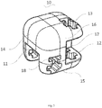
- first modules 10 first connecting groove 11; second connecting groove 12; cross grooves 13; first surface 14; second surface 15; third surface 16; fourth surface 17; deforming grooves 18; second module 20; connecting member 30; body portion 31; first pivoting portion 32; second pivoting portion 33; pivoting shaft 40.
- first information may also be referred to as second information.
- second information may also be referred to as first information.
- a term “if” as used herein can be interpreted as "when", “while” or "in response to”.
- the folding toy 100 (or the toy 100) includes first modules 10 (or first cubic blocks 10) in cubic shapes, second modules 20 (or second cubic blocks 20) in cubic shapes, and connecting members 30 (or connectors 30) each having two ends pivotally connected to the first module 10 and the second module 20 respectively.
- the folding toy 100 includes four first modules 10, four second modules 20, and eight connecting members 30 (or connectors 30) each having two ends pivotally connected to the first module 10 and the second module 20 respectively.
- the folding toy 100 includes pivoting shafts 40.
- Each of the first module 10 and the second module 20 may rotate around a respective pivoting shaft 40.
- each of the connecting members 30 includes a respective pivoting shaft 40.
- the edge length of the first module 10 is equal to that of the second module 20.
- the first modules 10 and the second modules 20 are arranged in a staggered manner.
- the connecting members 30 are configured to connect the first modules 10 and the second modules 20 adjacent to each other to form two parallel rows.
- the first modules 10 and the second modules 20 form two parallel rows, wherein the first row includes two first modules 10 and two second modules 20, the first modules 10 and the second modules 20 are spaced apart from each other, the second row also includes two first modules 10 and two second modules 20, and the first modules 10 and the second modules 20 are also spaced apart from each other.
- the first modules 10 in the first row are adjacent to the second modules 20 in the second row, such that the first modules 10 and the second modules 20 in the folding toy 100 are staggered.
- edges and corners of the first modules 10 and the second modules 20 are rounded corners.
- one of the first cubic blocks and the second cubic blocks includes a rounded edge and/or a rounded corner.
- the first modules 10 and the second modules 20 in the folding toy 100 are arranged in a staggered manner.
- Middle positions of two edges of each of the first modules 10 and the second modules 20 are provided with an accommodating space (or a recessed space) which is formed by recessing the corresponding edge in a direction from two surfaces where the edge is located toward the center of the module.
- the two edges are perpendicular to each other and do not intersect.
- Two ends of the connecting member 30 are respectively connected to the adjacent first module 10 and second module 20.
- the two ends of the connecting member 30 are at least partially accommodated in the accommodating space of the first module 10 and the second module 20.
- the connecting member 30 is located at the middle position of the first module 10 and the second module 20, such that force-bearing performance is good.
- the connecting member 30 is partially accommodated in the accommodating space of the first module 10 or the second module 20, such that deformation space is large, which is more flexible. Moreover, when two inner side walls of the accommodating space are perpendicular to each other, a rotation range of the connecting member 30 may be determined, and meanwhile the connecting member 30 and the inner side walls may be closely fit, which reduces the gap between the connecting member 30 and the first module 10 or the second module 20 and reduces the space used for rotating the folding toy 100. Besides, the change in the gap between the first module 10 and the second module 20, after the folding toy 100 is deformed, is small.
- Each first module 10 is connected to two adjacent second modules 20, and pivoting shafts 40 of the two connecting members 30 pivotally connected to each first module 10 are perpendicular to each other.
- the second modules 20 and the first modules 10 are spaced apart from each other.
- each second module 20 is connected to two adjacent first modules 10, and pivoting shafts 40 of the two connecting members 30 pivotally connected to each second module 20 are perpendicular to each other.
- the folding toy 100 may be unfolded to form two parallel rows of rectangular solids constituted by the first modules 10 and the second modules 20; or may be folded to form a cube constituted by the first modules 10 and the second modules 20.
- the folding toy 100 is comprised of eight small cubes and eight connecting members 30 combined to form a whole.
- the folding toy 100 may be rotated around the pivoting shafts 40 from a plurality of directions and angles. When a player holds the folding toy 100 in his/her hand, he/she may freely turn over the folding toy 100 following his/her feeling without restriction, the rotation is flexible, and the operation experience is excellent.
- the folding toy 100 may be manipulated in hands of the player, turned and stacked to form a large cube, or unfolded to form two paralleling rows of rectangular solids, which improves attentiveness of the player and relieves emotion of the player.
- the folding toy 100 has a small size, which may be moved at fingertips of the player. The user experience is good.
- the first module 10 and the second module 20 may be designed according to an appearance and a function. Holes, bumps, patterns and the like may be set and adjusted on the surface thereof to improve appearance. Both the first module 10 and the second module 20 are connected to the connecting member 30. In some embodiments, the first module 10 is configured to rotate around a respective pivoting shaft 40 in the connecting member 30. In some embodiments, the second module 20 is configured to rotate around a respective pivoting shaft 40 in the connecting member 30. In an embodiment, the first module 10 and the second module 20 are symmetrical in structure. The connecting member 30 is configured to be connected to the first module 10 and the second module 20. The first module 10 and the second module 20 are symmetrical in structure, which improves the overall uniformity of the folding toy 100 and the appearance is attractive. In the rotation process of the folding toy 100, the rotation is flexible, and has an excellent consistency.
- the first module 10 and the second module 20 are symmetrically disposed, and the first module 10 is taken as an example for description.
- the first module 10 includes a first connecting groove 11 (or a first groove 11) and a second connecting groove 12 (or a second groove 12) recessed from the surface of the first module 10.
- the first connecting groove 11 and the second connecting groove 12 are perpendicular to each other.
- the connecting member 30 may be connected to an interior of the corresponding first connecting groove 11 or second connecting groove 12.
- Each of the first connecting groove 11 and the second connecting groove 12 may be respectively connected to one connecting member 30.
- each of the first connecting groove 11 and the second connecting groove 12 is configured to rotate inside the respective connecting member 30.
- the first connecting groove 11 and the second connecting groove 12 are set by being recessed on the first module 10 to form the accommodating space, for respectively accommodating a part of the connecting member 30, to increase the volume of the connecting member 30 and improve strength and rigidity of the connecting member 30.
- the connecting member 30 is trapped in the first connecting groove 11 or the second connecting groove 12, so as to adjust the rotation position and the fitting position between the first module 10 and the second module 20 and make the rotation flexible.
- the first connecting groove 11 is located at the middle position of an edge (or a first edge) of the first module 10. By providing the first connecting groove 11 at the middle position of the edge, it may guarantee, for example, that the first module 10 is at a symmetrical position, the rotational position is the same and the stability is good, regardless of the direction in which the first module 10 is rotated.
- the first connecting groove 11 is formed by a recess downward from the surface of the first module 10.
- the first connecting groove 11 is partially recessed in a direction from a first surface 14 (or a first outer surface 14) of the first module 10 toward the center of the first module 10 to form a first bayonet (or a first slot), and the first connecting groove 11 extends to a side to a second surface 15 (or a second outer surface 15) perpendicular to the first surface 14.
- the first connecting groove 11 is a rectangular or trapezoidal notch on the first module 10.
- the opening of the first connecting groove 11 is located at the first surface 14 and the second surface 15 perpendicular to each other.
- the connecting member 30 may be connected to the first connecting groove 11 and may be perpendicular to the first surface 14 or the second surface 15 during the rotation.
- a pivoting shaft 40 in the first connecting groove 11 is configured to rotate inside the connecting member 30.
- the first connecting groove 11 forms two inner wall surfaces on the inner surface of the first module 10.
- a recession depth of the first connecting groove 11 from the first surface 14 of the first module 10 toward the center of the first module 10 is greater than or equal to one half of the edge length of the first module 10.
- a minimum distance between the second surface 15 and an inner wall surface of the first connecting groove 11 is greater than or equal to one half of the edge length of the first module 10.
- the two inner wall surfaces are perpendicular to each other.
- the distance between the opening of the first connecting groove 11 and the inner wall surface of the first connecting groove 11 is greater than or equal to one half of the edge length of the first module 10, that is, distance between the first surface 14 or the second surface 15 and an inner wall surface of the first connecting groove 11, which is not adjacent to the surface, is greater than or equal to one half of the edge length of the first module 10, and the rotatable range of the connecting member 30 is large, such that the first module 10 and the second module 20 may remain flush with each other after rotation.
- the first module 10 has a cubic shape and includes six surfaces, wherein the first surface 14 and the second surface 15 are perpendicular to each other, a third surface 16 (or a third outer surface 16) is perpendicular to both the first surface 14 and the second surface 15, and a fourth surface 17 (or a fourth outer surface 17) is parallel to the first surface 14 and perpendicular to the second surface 15.
- the first connecting groove 11 is disposed on the first surface 14 and the second surface 15.
- the second connecting groove 12 is partially recessed in a direction from the third surface 16 of the first module 10 toward the center of the first module 10 to form a second bayonet (or a second slot), and the second connecting groove 12 extends to a side to the fourth surface 17 perpendicular to the third surface 16.
- the first connecting groove 11 and the second connecting groove 12 are respectively located on two perpendicular edges, and surfaces, at which the openings of the first connecting groove 11 and the second connecting groove 12 are located, are different, such that the first module 10 may rotate around two directions perpendicular to each other.
- the first module 10 and the second module 20 that are arranged side by side may fit together after being rotated by 90 degrees simultaneously.
- a recession depth of the second connecting groove 12 from the third surface 16 of the first module 10 toward the center of the first module 10 is greater than or equal to one half of the edge length of the first module 10, and a minimum distance between the fourth surface 17 and an inner wall surface of the second connecting groove 12, which is not adjacent to fourth surface 17, is greater than or equal to one half of the edge length of the first module 10.
- the distance between the opening of the second connecting groove 12 and the inner wall surface of the second connecting groove 12 is greater than or equal to one half of the edge length of the first module 10, that is, distance between the third surface 16 or the fourth surface 17 and an inner wall surface of the second connecting groove 12, which is not adjacent to the surface, is greater than or equal to one half of the edge length of the first module 10, and the rotatable range of the connecting member 30 is large, such that the first module 10 and the second module 20 may remain flush with each other after rotation.
- the connecting member 30 is configured to pivotally connect the adjacent first module 10 and second module 20, wherein the connecting member 30 is a rigid structure.
- the connecting member 30 includes a body portion 31, a first pivoting portion 32 (or a first pivoting end 32) disposed at one end of the body portion 31 and a second pivoting portion 33 (or a second pivoting end 33) provided at the other end of the body portion 31.
- the first pivoting portion 32 is pivotally connected to the first module 10, and the second pivoting portion 33 is pivotally connected to the second module 20.
- the structures of the first module 10 and the second module 20 are symmetrical to each other.
- the first pivoting portion 32 is located in the first connecting groove 11 of the first module 10, and the second pivoting portion 33 is located in a corresponding groove position of the second module 20.
- the distance between the first module 10 and the second module 20 is adjusted through the length of the connecting member 30.
- the length of the connecting member 30 By adjusting the length of the connecting member 30, the distance between the first module 10 and the second module 20 is minimized.
- the fourth surfaces 17 of the first module 10 and second module 20 juxtaposed at the ends are fitted to each other.
- the third surface 16 of the first module 10 is fitted to the third surface 16 of the second module 20.
- the connecting members 30 connect the first modules 10 and the second modules 20 in sequence, to make the folding toy 100 to be formed as a whole.
- the folding toy 100 is compact and the appearance after deformation is pleasing.
- the folding toy 100 may be turned and bent in various angles, to improve its deformation ability. For example, when the folding toy 100 is in a rectangular solid state, after it is turned over from the center of the long side to both flank sides, the two rows of modules, after being rotated, continue to maintain the rectangular solid state, and the fitting surfaces of the two rows of modules are changed.
- the connecting member 30 is changed with respect to the first module 10 and the second module 20.
- the first pivoting portion 32 is pivotally connected to interior of the first module 10
- the second pivoting portion 33 is pivotally connected to interior of the second module 20.
- the connecting member 30 When the connecting member 30 is rotated 90 degrees with respect to the first module 10 and the connecting member 30 is perpendicular to the second surface 15, the outwardly-facing surface of the connecting member 30 is accordingly flush with the first surface 14.
- the pivoting shaft 40 of the connecting member 30 is parallel to the edge formed by intersecting the first surface 14 and the second surface 15. The distance from the pivoting shaft 40 to the first surface 14 is equal to the distance from the pivoting shaft 40 to the second surface 15.
- the connecting member 30 rotates around the pivoting shaft 40, and the outer surface of the connecting member 30 after rotating is flush with the surfaces of the first module 10 and the second module 20.
- the overall appearance is attractive. Accordingly, end portions of the first pivoting portion 32 and the second pivoting portion 33 are provided with circular arc surfaces, such that the connecting member 30 may rotate around the first module 10 or the second module 20, without interfering with each other.
- the connecting member 30 is pivotally connected to the first module 10 or the second module 20, wherein the connecting member 30 further includes protruding pivoting shafts 40 for pivotally connecting the connecting member 30 with the first module 10 or the second module 20.
- the form of providing the pivoting shafts 40 on the connecting member 30 may include an integrated form and a combined form.
- the pivoting shaft 40 is a shaft-shaped protrusion protruding from both sides of the body portion 31 of the connecting member 30, which is accordantly connected with the first module 10 or the second module 20, such that the connecting member 30 rotates around the pivoting shaft 40.
- the pivoting shaft 40 and the body portion 31 are plug-connected.
- a cross section of the pivoting shaft 40 is cross-shaped, and both the first module 10 and the second module 20 are provided with cross grooves 13 matched with the pivoting shaft 40, and the pivoting shaft 40 is assembled to the cross grooves 13, such that the connecting member 30 is connected to the first module 10 or the second module 20.
- the cross groove 13 is parallel to the edge of the first module 10.
- the first module 10 is provided with two sets of cross grooves 13 perpendicular to each other.
- the cross groove 13 penetrates through the first module 10.
- a set of cross grooves 13 are perpendicular to the first connecting groove 11 and penetrate into the first connecting groove 11.
- the other set of cross grooves 13 are perpendicular to the second connecting groove 12 and penetrate into the second connecting groove 12.
- the pivoting shaft 40 passes through the cross groove 13 and penetrates through one end of the connecting member 30, to make the connecting member 30 rotate around the pivoting shaft 40.
- the pivoting shaft 40 is set in a cross shape, to prevent the pivoting shaft 40 from rotating around itself, so as to ensure the reliability of rotation of the connecting member 30.
- an outer surface of the pivoting shaft 40 is located on a circumscribed circle, such that the connecting member 30 may rotate around the pivoting shaft 40 flexibly.
- the first module 10 is further provided with deforming grooves 18.
- Each of the deforming grooves 18 is parallel to a corresponding cross groove 13, opened and connected to one end of the cross groove 13 to form a structure similar to a Chinese character " ⁇ ".
- the deforming groove 18 is provided to absorb the deformation caused by extrusion from the pivoting shaft 40 and the cross groove 13. In this way, the pivoting shaft 40 and the cross groove 13 are interference fit, which makes the installation firm and facilitates the assembling.
- the folding toy 100 is a fingertip toy, which may be operated without a platform. Since the folding toy 100 directly contacts with the hand of a user as a fingertip toy, the tactile feel of the folding toy 100 is a significant experience effect of the user.
- outer surfaces of both the first module 10 and the second module 20 are frosted surfaces. When the user rotates the folding toy 100, the finger skin of the user is in contact with the frosted surface, the tactile feel is good, the user experience is excellent, and the flexibility of rotation is improved.
- the folding toy 100 is a fingertip toy that relieves the emotions of a user.
- the size of such a folding toy 100 is relatively small, which is suitable for use in environments such as offices and study rooms.
- different appearance and user experience may be achieved by adjusting material colors of the first module 10, the second module 20, the connecting member 30 and the pivoting shaft 40, such as using metal, plastic, wood and the combination thereof.
Landscapes
- Engineering & Computer Science (AREA)
- Multimedia (AREA)
- Toys (AREA)
Claims (15)
- Spielzeug, umfassend:
erste würfelförmige Blöcke (10), wobei jeder der ersten würfelförmigen Blöcke (10) Folgendes aufweist:eine erste Vertiefung, die von einer ersten Kante zu einem ersten Mittelpunkt des jeweiligen ersten würfelförmigen Blocks (10) reicht; undeine zweite Vertiefung, di von einer zweiten Kante des jeweiligen ersten würfelförmigen Blocks (10) zum ersten Mittelpunkt reicht, wobei die zweite Kante senkrecht zur ersten Kante ausgerichtet ist und sich nicht mit dieser schneidet;zweite würfelförmige Blöcke (20), wobei jeder der zweiten würfelförmigen Blöcke (20) Folgendes aufweist:eine dritte Vertiefung, die von einer dritten Kante zu einem zweiten Mittelpunkt des jeweiligen zweiten würfelförmigen Blocks (20) reicht; undeine vierte Vertiefung, die von einer vierten Kante des jeweiligen zweiten würfelförmigen Blocks (20) zum zweiten Mittelpunkt reicht, wobei die vierte Kante senkrecht zur dritten Kante ausgerichtet ist und sich nicht mit dieser schneidet;Verbindungsstücke (30), wobei jedes der Verbindungsstücke (30) einen der ersten würfelförmigen Blöcke (10) und einen der zweiten würfelförmigen Blöcke (20) verbindet; unddrehbare Achsen (40), wobei jede der drehbaren Achsen (40) eines der Verbindungsstücke (30) mit einem der ersten würfelförmigen Blöcke (10) und der zweiten würfelförmigen Blöcken (20) verbindet, der so konfiguriert ist, dass er sich um die jeweilige drehbare Achse (40) dreht,wobei eine Anzahl der ersten würfelförmigen Blöcke (10) gleich vier ist; eine Anzahl der zweiten würfelförmigen Blöcke (20) gleich vier ist;die ersten würfelförmigen Blöcke (10) und die zweiten würfelförmigen Blöcke (20) in einer versetzten Weise angeordnet sind, wobei der jeweilige erste würfelförmige Block (10) mit zwei der zweiten würfelförmigen Blöcke (20) unter Verwendung von zwei der Verbindungsstücke (30) in der ersten Vertiefung und der zweiten Vertiefung verbunden ist, und der jeweilige zweite würfelförmige Block (20) mit zwei der ersten würfelförmigen Blöcke (10) unter Verwendung von zwei der Verbindungsstücke (30) in der dritten Vertiefung und der vierten Vertiefung verbunden ist; undzwei der drehbaren Achsen (40), die senkrecht zueinander ausgerichtet sind, in jedem der ersten würfelförmigen Blöcke (10) und der zweiten würfelförmigen Blöcke (20) angeordnet sind, wobei der jeweilige erste würfelförmige Block (10) so konfiguriert ist, dass er sich um zwei jeweilige drehbare Achsen (40) dreht, und der jeweilige zweite würfelförmige Block (20) so konfiguriert ist, dass er sich um zwei jeweilige drehbare Achsen (40) dreht. - Spielzeug nach Anspruch 1, wobei eine Struktur des jeweiligen ersten würfelförmigen Blocks (10) symmetrisch zu einer Struktur des jeweiligen zweiten würfelförmigen Blocks (20) angeordnet ist.
- Spielzeug nach Anspruch 2, wobei die erste Vertiefung eine erste Nut (11) ist, die parallel zur ersten Kante angeordnet ist, und die zweite Vertiefung eine zweite Nut (12) ist, die parallel zur zweiten Kante angeordnet ist, wobei die erste Nut (11) senkrecht zur zweiten Nut (12) verläuft, wobei ein erstes drehbares Ende (32) des jeweiligen Verbindungsstücks (30) mit dem jeweiligen ersten würfelförmigen Block (10) in der ersten Nut (11) oder der zweiten Nut (12) verbunden ist.
- Spielzeug nach Anspruch 3, wobei
sich eine erste Außenfläche (14) und eine zweite Außenfläche (15) des jeweiligen ersten würfelförmigen Blocks (10) an der ersten Kante schneiden; und
die erste Nut (11) in einer Richtung von der ersten Außenfläche (14) zum ersten Mittelpunkt hin teilweise vertieft ist, um einen ersten Schlitz zu bilden, wobei die erste Nut (11) zur zweiten Außenfläche (15) senkrecht zur ersten Außenfläche (14) verläuft. - Spielzeug nach Anspruch 4, wobei eine Tiefe der ersten Nut (11) von der ersten Außenfläche (14) zum ersten Mittelpunkt hin größer oder gleich einer Hälfte einer Kantenlänge des jeweiligen ersten würfelförmigen Blocks (10) ist, und ein Mindestabstand zwischen der zweiten Außenfläche (15) und einer Innenwandfläche der ersten Nut (11) größer oder gleich einer Hälfte der Kantenlänge ist.
- Spielzeug nach Anspruch 4, wobei
sich eine dritte Außenfläche (16) und eine vierte Außenfläche (17) des jeweiligen ersten würfelförmigen Blocks (10) an der zweiten Kante schneiden; und
die zweite Nut (12) in einer Richtung von der dritten Außenfläche (16) zum ersten Mittelpunkt hin teilweise vertieft ist, um einen zweiten Schlitz zu bilden, wobei die zweite Nut (12) zur vierten Außenfläche (17) senkrecht zur dritten Außenfläche (16) verläuft. - Spielzeug nach Anspruch 6, wobei die dritte Außenfläche (16) senkrecht zu der ersten Außenfläche (14) und der zweiten Außenfläche (15) und die vierte Außenfläche (17) parallel zu der ersten Außenfläche (14) und senkrecht zu der zweiten Außenfläche (15) ausgerichtet ist.
- Spielzeug nach Anspruch 6, wobei eine Tiefe der zweiten Nut (12) von der dritten Außenfläche (16) zum ersten Mittelpunkt hin größer oder gleich der Hälfte der Kantenlänge ist und ein Mindestabstand zwischen der vierten Außenfläche (17) und einer inneren Wandfläche der zweiten Nut (12) größer oder gleich der Hälfte der Kantenlänge ist.
- Spielzeug nach Anspruch 3 oder ein davon abhängiger Anspruch, wobei jedes der Verbindungsstücke (30) Folgendes umfasst:einen Gebildeabschnitt (31), der zwischen dem ersten drehbaren Ende (32) und einem zweiten drehbaren Ende (33) angeordnet ist;das drehbare Ende (32), wobei sich ein Abschnitt des ersten drehbaren Endes (32) in einer der ersten Vertieftungen und der zweiten Vertiefungen des jeweiligen ersten würfelförmigen Blocks (10) befindet; unddas zweite drehbare Ende (33), wobei sich ein Abschnitt des zweiten drehbaren Endes (33) in einer der dritten Vertiefungen und der vierten Vertiefungen des jeweiligen zweiten würfelförmigen Blocks (20) befindet.
- Spielzeug nach Anspruch 9, wobei
das erste drehbare Ende (32) in der jeweiligen ersten Vertiefung und das zweite drehbare Ende (33) in der dritten Vertiefung angeordnet ist; und
wenn das jeweilige Verbindungsstück (30) in eine bestimmte Position gedreht wird, eine Außenfläche des Gebildeabschnitts (31) bündig mit entsprechenden Außenflächen des jeweiligen ersten würfelförmigen Blocks (10) und des jeweiligen zweiten würfelförmigen Blocks (20) ist. - Spielzeug nach Anspruch 9, wobei das Verbindungsstück (30) die drehbare Achse (40) umfasst, die aus dem Gebildeabschnitt (31) herausragt, wobei die drehbare Achse (40) den jeweiligen ersten würfelförmigen Block (10) mit dem Verbindungsstück (30) verbindet.
- Das Spielzeug nach Anspruch 11, wobei die drehbare Achse (40) in den Gebildeabschnitt (31) eingesteckt ist.
- Das Spielzeug nach Anspruch 11, wobei
ein Querschnitt der drehbaren Achse (40) kreuzförmig ist;
die erste Vertiefung zwischen einem Paar von Quernuten (13) in dem jeweiligen ersten würfelförmigen Block (10) angeordnet ist, wobei ein Querschnitt der jeweiligen Quernut (13) kreuzförmig ist und dem Querschnitt der drehbaren Achse (40) entspricht;
wobei die drehbare Achse (40) durch das jeweilige Paar von Quernuten (13) montiert ist, um die Drehung des jeweiligen ersten würfelförmigen Blocks (10) um die drehbare Achse (40) zu ermöglichen. - Spielzeug nach Anspruch 1, wobei einer der ersten würfelförmigen Blöcke (10) und der zweiten würfelförmigen Blöcke (20) eine abgerundete Kante und/oder eine abgerundete Ecke aufweist.
- Spielzeug nach Anspruch 1, wobei einer der ersten würfelförmigen Blöcke (10) und der zweiten würfelförmigen Blöcke (20) eine mattierte Außenfläche aufweist.
Applications Claiming Priority (1)
| Application Number | Priority Date | Filing Date | Title |
|---|---|---|---|
| CN201710832004.XA CN109499074A (zh) | 2017-09-15 | 2017-09-15 | 折叠玩具 |
Publications (2)
| Publication Number | Publication Date |
|---|---|
| EP3456396A1 EP3456396A1 (de) | 2019-03-20 |
| EP3456396B1 true EP3456396B1 (de) | 2020-05-13 |
Family
ID=63579059
Family Applications (1)
| Application Number | Title | Priority Date | Filing Date |
|---|---|---|---|
| EP18194024.8A Active EP3456396B1 (de) | 2017-09-15 | 2018-09-12 | Klappspielzeug |
Country Status (5)
| Country | Link |
|---|---|
| US (1) | US20190083894A1 (de) |
| EP (1) | EP3456396B1 (de) |
| JP (1) | JP2019530480A (de) |
| CN (1) | CN109499074A (de) |
| WO (1) | WO2019052106A1 (de) |
Families Citing this family (2)
| Publication number | Priority date | Publication date | Assignee | Title |
|---|---|---|---|---|
| US11123649B1 (en) * | 2020-05-29 | 2021-09-21 | Charles D. Kownacki | Moov fidget toy |
| KR102695419B1 (ko) * | 2022-01-24 | 2024-08-13 | 이보름 | 피젯 토이 |
Family Cites Families (23)
| Publication number | Priority date | Publication date | Assignee | Title |
|---|---|---|---|---|
| AT282429B (de) * | 1967-01-02 | 1970-06-25 | Wolfgang Dr Boeck-Greissau | Aus mehreren, längs Kanten gelenkig miteinander verbundenen orthogonalen Prismen bestehender Körper |
| JPS59200676A (ja) * | 1983-04-28 | 1984-11-14 | 株式会社バンダイ | 鎖状ブロツク玩具 |
| CN2124748U (zh) * | 1992-06-08 | 1992-12-16 | 洪文炳 | 可任意建构的组合性元件 |
| US5538452A (en) * | 1995-03-20 | 1996-07-23 | Kurani; Nadim K. | Puzzle toy with hinge-linked members |
| US5575120A (en) * | 1995-06-06 | 1996-11-19 | Handley; Frederick G. | Design and construction module |
| DE19857159A1 (de) * | 1998-12-11 | 2000-06-15 | Michael Schnabel | Universelle Lern- und Spieleinrichtung für Behinderte |
| CN2394683Y (zh) * | 1999-11-19 | 2000-09-06 | 麦元新 | 三度空间益智积木 |
| US8715029B2 (en) * | 2007-05-11 | 2014-05-06 | Forrest Frederick Bishop | Robotic construction cubes |
| DK2259853T3 (da) * | 2008-04-03 | 2013-02-25 | 3L Plentyplay Aps | Legetøjsklods, legetøjsklodsforbindelsesled og legetøjsklodselement til fremstilling af en legetøjsklods |
| KR101186479B1 (ko) * | 2010-01-07 | 2012-09-27 | (주)에프디스토리 | 폴딩 구조체 |
| CN201692659U (zh) * | 2010-06-18 | 2011-01-05 | 王小勇 | 一种拼接玩具 |
| CN202105437U (zh) * | 2011-03-31 | 2012-01-11 | 广州市雨禾玩具实业有限公司 | 一种插接玩具基块 |
| CN104039406B (zh) * | 2011-10-31 | 2017-05-24 | 模块化机器人公司 | 模块式运动学构造套件 |
| CN104080521A (zh) * | 2012-02-06 | 2014-10-01 | 柳贞根 | 用于组装块体玩具的旋转连接块 |
| CN103055518A (zh) * | 2012-12-10 | 2013-04-24 | 宁波市米乐玩具礼品有限公司 | 一种积木飞机的结构及其组合方法 |
| CN103071299A (zh) * | 2012-12-10 | 2013-05-01 | 宁波市米乐玩具礼品有限公司 | 一种积木机器人及拆装方法 |
| WO2014106796A1 (en) * | 2013-01-02 | 2014-07-10 | BROOMBERG, Ryan | Apparatus for playing a game |
| DE102014005386A1 (de) * | 2013-05-15 | 2014-11-20 | CVASSO GmbH | Modulares Polyederobjekt |
| CN204121774U (zh) * | 2014-10-28 | 2015-01-28 | 陶宇晨 | 一种拼接玩具的动力模块 |
| KR101654560B1 (ko) * | 2015-05-19 | 2016-09-06 | 오승영 | 결합부와 삽입부가 일체로 제공되는 단위블록 및 이를 이용한 결합 또는 이용방법 |
| BR102015011928A2 (pt) * | 2015-05-22 | 2017-01-17 | Janete Zen | brinquedo lúdico em blocos intercambiáveis e método de travamento de blocos intercambiáveis |
| CN206063793U (zh) * | 2016-06-30 | 2017-04-05 | 上海未来伙伴机器人有限公司 | 积木扩展连接构件 |
| CN207203477U (zh) * | 2017-09-15 | 2018-04-10 | 北京小米移动软件有限公司 | 折叠玩具 |
-
2017
- 2017-09-15 CN CN201710832004.XA patent/CN109499074A/zh active Pending
-
2018
- 2018-01-17 JP JP2018515873A patent/JP2019530480A/ja active Pending
- 2018-01-17 WO PCT/CN2018/073089 patent/WO2019052106A1/zh not_active Ceased
- 2018-08-10 US US16/100,834 patent/US20190083894A1/en not_active Abandoned
- 2018-09-12 EP EP18194024.8A patent/EP3456396B1/de active Active
Non-Patent Citations (1)
| Title |
|---|
| None * |
Also Published As
| Publication number | Publication date |
|---|---|
| EP3456396A1 (de) | 2019-03-20 |
| WO2019052106A1 (zh) | 2019-03-21 |
| JP2019530480A (ja) | 2019-10-24 |
| CN109499074A (zh) | 2019-03-22 |
| US20190083894A1 (en) | 2019-03-21 |
Similar Documents
| Publication | Publication Date | Title |
|---|---|---|
| US7823884B2 (en) | Spherical puzzle | |
| CN104174169B (zh) | 一种可自动分体的组合式玩具陀螺 | |
| US4441715A (en) | Spherical puzzle | |
| US10737191B2 (en) | Assembly unit for toy assembly block | |
| CN103492035B (zh) | 游戏件 | |
| EP3456396B1 (de) | Klappspielzeug | |
| WO1994004236A1 (en) | A puzzle | |
| EP1291051A2 (de) | Dreidimensionales Aufbauspielzeug mit frei verbindbaren Teilen | |
| CN105251202A (zh) | 多功能拼接积木构件及玩具 | |
| US6419542B1 (en) | Three-dimensional toy built up with freely connectable parts | |
| KR20110099660A (ko) | 변형블록 | |
| CN207203477U (zh) | 折叠玩具 | |
| EP2762217A1 (de) | Geometrische Systeme zum Aufbau von 3D-Strukturen | |
| JP3222565U (ja) | 一種の新型マグネチック立体パズルキューブ | |
| TWI743571B (zh) | 可切換路徑變化之立體迷宮結構 | |
| KR200399428Y1 (ko) | 1면 다극 자석이 결합된 자석 완구 | |
| KR101389927B1 (ko) | 블록 어셈블리 및 이를 위한 블록 커넥터 | |
| US6199865B1 (en) | Logical game element | |
| CN205992125U (zh) | 拼图时钟 | |
| CN108096825B (zh) | 一种可旋转字符魔方 | |
| US20230061964A1 (en) | Construction support device | |
| JP3158393U (ja) | 視覚障害者用ルービック遊戯具 | |
| US20160263475A1 (en) | Multi-trench 3d magic ball | |
| CN114570038B (zh) | 模块式榫卯拼装积木及拼装积木结构 | |
| CN113967359B (zh) | 卯榫积木及卯榫积木系统 |
Legal Events
| Date | Code | Title | Description |
|---|---|---|---|
| PUAI | Public reference made under article 153(3) epc to a published international application that has entered the european phase |
Free format text: ORIGINAL CODE: 0009012 |
|
| STAA | Information on the status of an ep patent application or granted ep patent |
Free format text: STATUS: THE APPLICATION HAS BEEN PUBLISHED |
|
| AK | Designated contracting states |
Kind code of ref document: A1 Designated state(s): AL AT BE BG CH CY CZ DE DK EE ES FI FR GB GR HR HU IE IS IT LI LT LU LV MC MK MT NL NO PL PT RO RS SE SI SK SM TR |
|
| AX | Request for extension of the european patent |
Extension state: BA ME |
|
| STAA | Information on the status of an ep patent application or granted ep patent |
Free format text: STATUS: REQUEST FOR EXAMINATION WAS MADE |
|
| 17P | Request for examination filed |
Effective date: 20190920 |
|
| RBV | Designated contracting states (corrected) |
Designated state(s): AL AT BE BG CH CY CZ DE DK EE ES FI FR GB GR HR HU IE IS IT LI LT LU LV MC MK MT NL NO PL PT RO RS SE SI SK SM TR |
|
| GRAP | Despatch of communication of intention to grant a patent |
Free format text: ORIGINAL CODE: EPIDOSNIGR1 |
|
| STAA | Information on the status of an ep patent application or granted ep patent |
Free format text: STATUS: GRANT OF PATENT IS INTENDED |
|
| INTG | Intention to grant announced |
Effective date: 20200207 |
|
| GRAS | Grant fee paid |
Free format text: ORIGINAL CODE: EPIDOSNIGR3 |
|
| GRAA | (expected) grant |
Free format text: ORIGINAL CODE: 0009210 |
|
| STAA | Information on the status of an ep patent application or granted ep patent |
Free format text: STATUS: THE PATENT HAS BEEN GRANTED |
|
| AK | Designated contracting states |
Kind code of ref document: B1 Designated state(s): AL AT BE BG CH CY CZ DE DK EE ES FI FR GB GR HR HU IE IS IT LI LT LU LV MC MK MT NL NO PL PT RO RS SE SI SK SM TR |
|
| REG | Reference to a national code |
Ref country code: GB Ref legal event code: FG4D |
|
| REG | Reference to a national code |
Ref country code: CH Ref legal event code: EP |
|
| REG | Reference to a national code |
Ref country code: DE Ref legal event code: R096 Ref document number: 602018004529 Country of ref document: DE |
|
| REG | Reference to a national code |
Ref country code: AT Ref legal event code: REF Ref document number: 1269490 Country of ref document: AT Kind code of ref document: T Effective date: 20200615 |
|
| REG | Reference to a national code |
Ref country code: LT Ref legal event code: MG4D |
|
| REG | Reference to a national code |
Ref country code: NL Ref legal event code: MP Effective date: 20200513 |
|
| PG25 | Lapsed in a contracting state [announced via postgrant information from national office to epo] |
Ref country code: IS Free format text: LAPSE BECAUSE OF FAILURE TO SUBMIT A TRANSLATION OF THE DESCRIPTION OR TO PAY THE FEE WITHIN THE PRESCRIBED TIME-LIMIT Effective date: 20200913 Ref country code: PT Free format text: LAPSE BECAUSE OF FAILURE TO SUBMIT A TRANSLATION OF THE DESCRIPTION OR TO PAY THE FEE WITHIN THE PRESCRIBED TIME-LIMIT Effective date: 20200914 Ref country code: GR Free format text: LAPSE BECAUSE OF FAILURE TO SUBMIT A TRANSLATION OF THE DESCRIPTION OR TO PAY THE FEE WITHIN THE PRESCRIBED TIME-LIMIT Effective date: 20200814 Ref country code: NO Free format text: LAPSE BECAUSE OF FAILURE TO SUBMIT A TRANSLATION OF THE DESCRIPTION OR TO PAY THE FEE WITHIN THE PRESCRIBED TIME-LIMIT Effective date: 20200813 Ref country code: FI Free format text: LAPSE BECAUSE OF FAILURE TO SUBMIT A TRANSLATION OF THE DESCRIPTION OR TO PAY THE FEE WITHIN THE PRESCRIBED TIME-LIMIT Effective date: 20200513 Ref country code: SE Free format text: LAPSE BECAUSE OF FAILURE TO SUBMIT A TRANSLATION OF THE DESCRIPTION OR TO PAY THE FEE WITHIN THE PRESCRIBED TIME-LIMIT Effective date: 20200513 Ref country code: LT Free format text: LAPSE BECAUSE OF FAILURE TO SUBMIT A TRANSLATION OF THE DESCRIPTION OR TO PAY THE FEE WITHIN THE PRESCRIBED TIME-LIMIT Effective date: 20200513 |
|
| PG25 | Lapsed in a contracting state [announced via postgrant information from national office to epo] |
Ref country code: BG Free format text: LAPSE BECAUSE OF FAILURE TO SUBMIT A TRANSLATION OF THE DESCRIPTION OR TO PAY THE FEE WITHIN THE PRESCRIBED TIME-LIMIT Effective date: 20200813 Ref country code: HR Free format text: LAPSE BECAUSE OF FAILURE TO SUBMIT A TRANSLATION OF THE DESCRIPTION OR TO PAY THE FEE WITHIN THE PRESCRIBED TIME-LIMIT Effective date: 20200513 Ref country code: RS Free format text: LAPSE BECAUSE OF FAILURE TO SUBMIT A TRANSLATION OF THE DESCRIPTION OR TO PAY THE FEE WITHIN THE PRESCRIBED TIME-LIMIT Effective date: 20200513 Ref country code: LV Free format text: LAPSE BECAUSE OF FAILURE TO SUBMIT A TRANSLATION OF THE DESCRIPTION OR TO PAY THE FEE WITHIN THE PRESCRIBED TIME-LIMIT Effective date: 20200513 |
|
| REG | Reference to a national code |
Ref country code: AT Ref legal event code: MK05 Ref document number: 1269490 Country of ref document: AT Kind code of ref document: T Effective date: 20200513 |
|
| PG25 | Lapsed in a contracting state [announced via postgrant information from national office to epo] |
Ref country code: AL Free format text: LAPSE BECAUSE OF FAILURE TO SUBMIT A TRANSLATION OF THE DESCRIPTION OR TO PAY THE FEE WITHIN THE PRESCRIBED TIME-LIMIT Effective date: 20200513 Ref country code: NL Free format text: LAPSE BECAUSE OF FAILURE TO SUBMIT A TRANSLATION OF THE DESCRIPTION OR TO PAY THE FEE WITHIN THE PRESCRIBED TIME-LIMIT Effective date: 20200513 |
|
| PG25 | Lapsed in a contracting state [announced via postgrant information from national office to epo] |
Ref country code: AT Free format text: LAPSE BECAUSE OF FAILURE TO SUBMIT A TRANSLATION OF THE DESCRIPTION OR TO PAY THE FEE WITHIN THE PRESCRIBED TIME-LIMIT Effective date: 20200513 Ref country code: EE Free format text: LAPSE BECAUSE OF FAILURE TO SUBMIT A TRANSLATION OF THE DESCRIPTION OR TO PAY THE FEE WITHIN THE PRESCRIBED TIME-LIMIT Effective date: 20200513 Ref country code: SM Free format text: LAPSE BECAUSE OF FAILURE TO SUBMIT A TRANSLATION OF THE DESCRIPTION OR TO PAY THE FEE WITHIN THE PRESCRIBED TIME-LIMIT Effective date: 20200513 Ref country code: DK Free format text: LAPSE BECAUSE OF FAILURE TO SUBMIT A TRANSLATION OF THE DESCRIPTION OR TO PAY THE FEE WITHIN THE PRESCRIBED TIME-LIMIT Effective date: 20200513 Ref country code: RO Free format text: LAPSE BECAUSE OF FAILURE TO SUBMIT A TRANSLATION OF THE DESCRIPTION OR TO PAY THE FEE WITHIN THE PRESCRIBED TIME-LIMIT Effective date: 20200513 Ref country code: IT Free format text: LAPSE BECAUSE OF FAILURE TO SUBMIT A TRANSLATION OF THE DESCRIPTION OR TO PAY THE FEE WITHIN THE PRESCRIBED TIME-LIMIT Effective date: 20200513 Ref country code: CZ Free format text: LAPSE BECAUSE OF FAILURE TO SUBMIT A TRANSLATION OF THE DESCRIPTION OR TO PAY THE FEE WITHIN THE PRESCRIBED TIME-LIMIT Effective date: 20200513 Ref country code: ES Free format text: LAPSE BECAUSE OF FAILURE TO SUBMIT A TRANSLATION OF THE DESCRIPTION OR TO PAY THE FEE WITHIN THE PRESCRIBED TIME-LIMIT Effective date: 20200513 |
|
| REG | Reference to a national code |
Ref country code: DE Ref legal event code: R097 Ref document number: 602018004529 Country of ref document: DE |
|
| PG25 | Lapsed in a contracting state [announced via postgrant information from national office to epo] |
Ref country code: PL Free format text: LAPSE BECAUSE OF FAILURE TO SUBMIT A TRANSLATION OF THE DESCRIPTION OR TO PAY THE FEE WITHIN THE PRESCRIBED TIME-LIMIT Effective date: 20200513 Ref country code: SK Free format text: LAPSE BECAUSE OF FAILURE TO SUBMIT A TRANSLATION OF THE DESCRIPTION OR TO PAY THE FEE WITHIN THE PRESCRIBED TIME-LIMIT Effective date: 20200513 |
|
| PLBE | No opposition filed within time limit |
Free format text: ORIGINAL CODE: 0009261 |
|
| STAA | Information on the status of an ep patent application or granted ep patent |
Free format text: STATUS: NO OPPOSITION FILED WITHIN TIME LIMIT |
|
| 26N | No opposition filed |
Effective date: 20210216 |
|
| PG25 | Lapsed in a contracting state [announced via postgrant information from national office to epo] |
Ref country code: SI Free format text: LAPSE BECAUSE OF FAILURE TO SUBMIT A TRANSLATION OF THE DESCRIPTION OR TO PAY THE FEE WITHIN THE PRESCRIBED TIME-LIMIT Effective date: 20200513 |
|
| REG | Reference to a national code |
Ref country code: BE Ref legal event code: MM Effective date: 20200930 |
|
| PG25 | Lapsed in a contracting state [announced via postgrant information from national office to epo] |
Ref country code: LU Free format text: LAPSE BECAUSE OF NON-PAYMENT OF DUE FEES Effective date: 20200912 |
|
| PG25 | Lapsed in a contracting state [announced via postgrant information from national office to epo] |
Ref country code: BE Free format text: LAPSE BECAUSE OF NON-PAYMENT OF DUE FEES Effective date: 20200930 Ref country code: IE Free format text: LAPSE BECAUSE OF NON-PAYMENT OF DUE FEES Effective date: 20200912 |
|
| REG | Reference to a national code |
Ref country code: CH Ref legal event code: PL |
|
| PG25 | Lapsed in a contracting state [announced via postgrant information from national office to epo] |
Ref country code: TR Free format text: LAPSE BECAUSE OF FAILURE TO SUBMIT A TRANSLATION OF THE DESCRIPTION OR TO PAY THE FEE WITHIN THE PRESCRIBED TIME-LIMIT Effective date: 20200513 Ref country code: MT Free format text: LAPSE BECAUSE OF FAILURE TO SUBMIT A TRANSLATION OF THE DESCRIPTION OR TO PAY THE FEE WITHIN THE PRESCRIBED TIME-LIMIT Effective date: 20200513 Ref country code: CY Free format text: LAPSE BECAUSE OF FAILURE TO SUBMIT A TRANSLATION OF THE DESCRIPTION OR TO PAY THE FEE WITHIN THE PRESCRIBED TIME-LIMIT Effective date: 20200513 |
|
| PG25 | Lapsed in a contracting state [announced via postgrant information from national office to epo] |
Ref country code: MK Free format text: LAPSE BECAUSE OF FAILURE TO SUBMIT A TRANSLATION OF THE DESCRIPTION OR TO PAY THE FEE WITHIN THE PRESCRIBED TIME-LIMIT Effective date: 20200513 Ref country code: MC Free format text: LAPSE BECAUSE OF FAILURE TO SUBMIT A TRANSLATION OF THE DESCRIPTION OR TO PAY THE FEE WITHIN THE PRESCRIBED TIME-LIMIT Effective date: 20200513 |
|
| PG25 | Lapsed in a contracting state [announced via postgrant information from national office to epo] |
Ref country code: LI Free format text: LAPSE BECAUSE OF NON-PAYMENT OF DUE FEES Effective date: 20210930 Ref country code: CH Free format text: LAPSE BECAUSE OF NON-PAYMENT OF DUE FEES Effective date: 20210930 |
|
| P01 | Opt-out of the competence of the unified patent court (upc) registered |
Effective date: 20230523 |
|
| PGFP | Annual fee paid to national office [announced via postgrant information from national office to epo] |
Ref country code: FR Payment date: 20230928 Year of fee payment: 6 |
|
| PG25 | Lapsed in a contracting state [announced via postgrant information from national office to epo] |
Ref country code: FR Free format text: LAPSE BECAUSE OF NON-PAYMENT OF DUE FEES Effective date: 20240930 |
|
| PGFP | Annual fee paid to national office [announced via postgrant information from national office to epo] |
Ref country code: DE Payment date: 20250919 Year of fee payment: 8 |
|
| PGFP | Annual fee paid to national office [announced via postgrant information from national office to epo] |
Ref country code: GB Payment date: 20250919 Year of fee payment: 8 |