EP3456396B1 - Folding toy - Google Patents
Folding toy Download PDFInfo
- Publication number
- EP3456396B1 EP3456396B1 EP18194024.8A EP18194024A EP3456396B1 EP 3456396 B1 EP3456396 B1 EP 3456396B1 EP 18194024 A EP18194024 A EP 18194024A EP 3456396 B1 EP3456396 B1 EP 3456396B1
- Authority
- EP
- European Patent Office
- Prior art keywords
- cubic
- groove
- module
- pivoting
- edge
- Prior art date
- Legal status (The legal status is an assumption and is not a legal conclusion. Google has not performed a legal analysis and makes no representation as to the accuracy of the status listed.)
- Active
Links
- 230000001419 dependent effect Effects 0.000 claims 1
- 239000007787 solid Substances 0.000 description 6
- 238000000034 method Methods 0.000 description 5
- 230000008451 emotion Effects 0.000 description 3
- 239000000463 material Substances 0.000 description 3
- 208000019901 Anxiety disease Diseases 0.000 description 2
- 230000036506 anxiety Effects 0.000 description 2
- 230000003340 mental effect Effects 0.000 description 2
- 239000002184 metal Substances 0.000 description 2
- 239000004033 plastic Substances 0.000 description 2
- 230000007306 turnover Effects 0.000 description 2
- 230000009286 beneficial effect Effects 0.000 description 1
- 239000003086 colorant Substances 0.000 description 1
- 238000010276 construction Methods 0.000 description 1
- 230000006837 decompression Effects 0.000 description 1
- 238000010586 diagram Methods 0.000 description 1
- 230000000694 effects Effects 0.000 description 1
- 238000005516 engineering process Methods 0.000 description 1
- 238000001125 extrusion Methods 0.000 description 1
- 230000005484 gravity Effects 0.000 description 1
- 238000009434 installation Methods 0.000 description 1
- 230000002452 interceptive effect Effects 0.000 description 1
- 239000002023 wood Substances 0.000 description 1
Images


Classifications
-
- A—HUMAN NECESSITIES
- A63—SPORTS; GAMES; AMUSEMENTS
- A63H—TOYS, e.g. TOPS, DOLLS, HOOPS OR BUILDING BLOCKS
- A63H33/00—Other toys
-
- A—HUMAN NECESSITIES
- A63—SPORTS; GAMES; AMUSEMENTS
- A63H—TOYS, e.g. TOPS, DOLLS, HOOPS OR BUILDING BLOCKS
- A63H33/00—Other toys
- A63H33/04—Building blocks, strips, or similar building parts
- A63H33/06—Building blocks, strips, or similar building parts to be assembled without the use of additional elements
- A63H33/067—Building blocks, strips, or similar building parts to be assembled without the use of additional elements with rotation or translation, e.g. of keyhole or bayonet type
-
- A—HUMAN NECESSITIES
- A63—SPORTS; GAMES; AMUSEMENTS
- A63H—TOYS, e.g. TOPS, DOLLS, HOOPS OR BUILDING BLOCKS
- A63H33/00—Other toys
- A63H33/04—Building blocks, strips, or similar building parts
- A63H33/10—Building blocks, strips, or similar building parts to be assembled by means of additional non-adhesive elements
- A63H33/105—Building blocks, strips, or similar building parts to be assembled by means of additional non-adhesive elements with grooves, e.g. dovetails
-
- A—HUMAN NECESSITIES
- A63—SPORTS; GAMES; AMUSEMENTS
- A63F—CARD, BOARD, OR ROULETTE GAMES; INDOOR GAMES USING SMALL MOVING PLAYING BODIES; VIDEO GAMES; GAMES NOT OTHERWISE PROVIDED FOR
- A63F9/00—Games not otherwise provided for
- A63F9/06—Patience; Other games for self-amusement
- A63F9/08—Puzzles provided with elements movable in relation, i.e. movably connected, to each other
- A63F9/088—Puzzles with elements that are connected by straps, strings or hinges, e.g. Rubik's Magic
-
- A—HUMAN NECESSITIES
- A63—SPORTS; GAMES; AMUSEMENTS
- A63H—TOYS, e.g. TOPS, DOLLS, HOOPS OR BUILDING BLOCKS
- A63H33/00—Other toys
- A63H33/04—Building blocks, strips, or similar building parts
-
- A—HUMAN NECESSITIES
- A63—SPORTS; GAMES; AMUSEMENTS
- A63H—TOYS, e.g. TOPS, DOLLS, HOOPS OR BUILDING BLOCKS
- A63H33/00—Other toys
- A63H33/04—Building blocks, strips, or similar building parts
- A63H33/042—Mechanical, electrical, optical, pneumatic or hydraulic arrangements; Motors
Definitions
- the present disclosure belongs to the field of toy technology.
- toys of building blocks are made of hard materials, such as wood, metal or hard plastic materials. Building blocks are separated from each other, which need to be stacked one by one on a platform by people, in order to build a variety of shapes.
- the built shape is influenced by gravity. Mutual forces among the building blocks and corresponding directions of the forces need to be adjusted, to build a corresponding shape.
- the number of the building blocks is relatively large, and the building blocks may occupy a large space.
- US 3, 550, 310 teaches a folding toy having pivotably connected cubic blocks, whereby the blocks can be rotated about connectors in different directions relative to each other.
- the present disclosure relates to a toy.
- the toy comprises:
- a structure of the respective first cubic block is symmetric with respect to a structure of the respective second cubic block.
- the first recessed space is a first groove disposed parallel to the first edge and the second recessed space is a second groove disposed parallel to the second edge, the first groove being perpendicular to the second groove, the first pivoting end of the respective connector being connected to the respective first cubic block in the first groove or the second groove.
- a first outer surface and a second outer surface of the respective first cubic block intercept at the first edge; and the first groove is partially recessed in a direction from the first outer surface toward the first center to form a first slot, the first groove extending to the second outer surface perpendicular to the first outer surface.
- a recessed depth of the first groove from the first outer surface toward the first center is greater than or equal to one half of an edge length of the respective first cubic block, and a minimum distance between the second outer surface and an inner wall surface of the first groove is greater than or equal to one half of the edge length.
- a third outer surface and a fourth outer surface of the respective first cubic block intercept at the second edge; and the second groove is partially recessed in a direction from the third outer surface toward the first center to form a second slot, the second groove extending to the fourth outer surface perpendicular to the third outer surface.
- the third outer surface is perpendicular to the first outer surface and the second outer surface
- the fourth outer surface is parallel to the first outer surface and perpendicular to the second outer surface
- a recession depth of the second groove from the third outer surface toward the first center is greater than or equal to one half of the edge length, and a minimum distance between the fourth outer surface and an inner wall surface of the second groove is greater than or equal to one half of the edge length.
- each of the connectors includes:
- the first pivoting end is disposed in the respective first recessed space, and the second pivoting end is disposed in the third recessed space; and when the respective connector is rotated to a specific position, an outer surface of the body portion is flush with corresponding outer surfaces of the respective first cubic block and the respective second cubic block.
- the connector comprises the pivoting shaft that protrudes outside of the body portion, the pivoting shaft connecting the respective first cubic block with the connector.
- the pivoting shaft is plugged into the body portion.
- a cross-section of the pivoting shaft is cross-shaped; the first recessed space is disposed between a pair of cross grooves in the respective first cubic block, a cross-section of the respective cross groove being cross-shaped and matching the cross-section of the pivoting shaft; the pivoting shaft is assembled through the respective pair of cross grooves to enable rotation of the respective first cubic block around the pivoting shaft.
- one of the first cubic blocks and the second cubic blocks comprises a rounded edge and/or a rounded corner.
- one of the first cubic blocks and the second cubic blocks comprises a frosted outer surface.
- the folding toy (or the toy) is combined by eight small cubes and connecting members to form a whole.
- the folding toy may be rotated around the pivoting shaft from a plurality of directions and angles. When a player holds the folding toy in his/her hand, he/she may freely turn over the folding toy following his/her feeling without restriction, the rotation is flexible and the operation experience is excellent.
- the folding toys may be manipulated in the hands of the player, turned and stacked to form a large cube, or unfolded to form two paralleling rows of rectangular solids, which improves attentiveness of the player and relieves anxiety of the player.
- the folding toy has a small size, which may be moved by the fingertips of the player. The user experience is good.
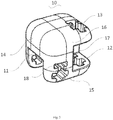
- first modules 10 first connecting groove 11; second connecting groove 12; cross grooves 13; first surface 14; second surface 15; third surface 16; fourth surface 17; deforming grooves 18; second module 20; connecting member 30; body portion 31; first pivoting portion 32; second pivoting portion 33; pivoting shaft 40.
- first information may also be referred to as second information.
- second information may also be referred to as first information.
- a term “if” as used herein can be interpreted as "when", “while” or "in response to”.
- the folding toy 100 (or the toy 100) includes first modules 10 (or first cubic blocks 10) in cubic shapes, second modules 20 (or second cubic blocks 20) in cubic shapes, and connecting members 30 (or connectors 30) each having two ends pivotally connected to the first module 10 and the second module 20 respectively.
- the folding toy 100 includes four first modules 10, four second modules 20, and eight connecting members 30 (or connectors 30) each having two ends pivotally connected to the first module 10 and the second module 20 respectively.
- the folding toy 100 includes pivoting shafts 40.
- Each of the first module 10 and the second module 20 may rotate around a respective pivoting shaft 40.
- each of the connecting members 30 includes a respective pivoting shaft 40.
- the edge length of the first module 10 is equal to that of the second module 20.
- the first modules 10 and the second modules 20 are arranged in a staggered manner.
- the connecting members 30 are configured to connect the first modules 10 and the second modules 20 adjacent to each other to form two parallel rows.
- the first modules 10 and the second modules 20 form two parallel rows, wherein the first row includes two first modules 10 and two second modules 20, the first modules 10 and the second modules 20 are spaced apart from each other, the second row also includes two first modules 10 and two second modules 20, and the first modules 10 and the second modules 20 are also spaced apart from each other.
- the first modules 10 in the first row are adjacent to the second modules 20 in the second row, such that the first modules 10 and the second modules 20 in the folding toy 100 are staggered.
- edges and corners of the first modules 10 and the second modules 20 are rounded corners.
- one of the first cubic blocks and the second cubic blocks includes a rounded edge and/or a rounded corner.
- the first modules 10 and the second modules 20 in the folding toy 100 are arranged in a staggered manner.
- Middle positions of two edges of each of the first modules 10 and the second modules 20 are provided with an accommodating space (or a recessed space) which is formed by recessing the corresponding edge in a direction from two surfaces where the edge is located toward the center of the module.
- the two edges are perpendicular to each other and do not intersect.
- Two ends of the connecting member 30 are respectively connected to the adjacent first module 10 and second module 20.
- the two ends of the connecting member 30 are at least partially accommodated in the accommodating space of the first module 10 and the second module 20.
- the connecting member 30 is located at the middle position of the first module 10 and the second module 20, such that force-bearing performance is good.
- the connecting member 30 is partially accommodated in the accommodating space of the first module 10 or the second module 20, such that deformation space is large, which is more flexible. Moreover, when two inner side walls of the accommodating space are perpendicular to each other, a rotation range of the connecting member 30 may be determined, and meanwhile the connecting member 30 and the inner side walls may be closely fit, which reduces the gap between the connecting member 30 and the first module 10 or the second module 20 and reduces the space used for rotating the folding toy 100. Besides, the change in the gap between the first module 10 and the second module 20, after the folding toy 100 is deformed, is small.
- Each first module 10 is connected to two adjacent second modules 20, and pivoting shafts 40 of the two connecting members 30 pivotally connected to each first module 10 are perpendicular to each other.
- the second modules 20 and the first modules 10 are spaced apart from each other.
- each second module 20 is connected to two adjacent first modules 10, and pivoting shafts 40 of the two connecting members 30 pivotally connected to each second module 20 are perpendicular to each other.
- the folding toy 100 may be unfolded to form two parallel rows of rectangular solids constituted by the first modules 10 and the second modules 20; or may be folded to form a cube constituted by the first modules 10 and the second modules 20.
- the folding toy 100 is comprised of eight small cubes and eight connecting members 30 combined to form a whole.
- the folding toy 100 may be rotated around the pivoting shafts 40 from a plurality of directions and angles. When a player holds the folding toy 100 in his/her hand, he/she may freely turn over the folding toy 100 following his/her feeling without restriction, the rotation is flexible, and the operation experience is excellent.
- the folding toy 100 may be manipulated in hands of the player, turned and stacked to form a large cube, or unfolded to form two paralleling rows of rectangular solids, which improves attentiveness of the player and relieves emotion of the player.
- the folding toy 100 has a small size, which may be moved at fingertips of the player. The user experience is good.
- the first module 10 and the second module 20 may be designed according to an appearance and a function. Holes, bumps, patterns and the like may be set and adjusted on the surface thereof to improve appearance. Both the first module 10 and the second module 20 are connected to the connecting member 30. In some embodiments, the first module 10 is configured to rotate around a respective pivoting shaft 40 in the connecting member 30. In some embodiments, the second module 20 is configured to rotate around a respective pivoting shaft 40 in the connecting member 30. In an embodiment, the first module 10 and the second module 20 are symmetrical in structure. The connecting member 30 is configured to be connected to the first module 10 and the second module 20. The first module 10 and the second module 20 are symmetrical in structure, which improves the overall uniformity of the folding toy 100 and the appearance is attractive. In the rotation process of the folding toy 100, the rotation is flexible, and has an excellent consistency.
- the first module 10 and the second module 20 are symmetrically disposed, and the first module 10 is taken as an example for description.
- the first module 10 includes a first connecting groove 11 (or a first groove 11) and a second connecting groove 12 (or a second groove 12) recessed from the surface of the first module 10.
- the first connecting groove 11 and the second connecting groove 12 are perpendicular to each other.
- the connecting member 30 may be connected to an interior of the corresponding first connecting groove 11 or second connecting groove 12.
- Each of the first connecting groove 11 and the second connecting groove 12 may be respectively connected to one connecting member 30.
- each of the first connecting groove 11 and the second connecting groove 12 is configured to rotate inside the respective connecting member 30.
- the first connecting groove 11 and the second connecting groove 12 are set by being recessed on the first module 10 to form the accommodating space, for respectively accommodating a part of the connecting member 30, to increase the volume of the connecting member 30 and improve strength and rigidity of the connecting member 30.
- the connecting member 30 is trapped in the first connecting groove 11 or the second connecting groove 12, so as to adjust the rotation position and the fitting position between the first module 10 and the second module 20 and make the rotation flexible.
- the first connecting groove 11 is located at the middle position of an edge (or a first edge) of the first module 10. By providing the first connecting groove 11 at the middle position of the edge, it may guarantee, for example, that the first module 10 is at a symmetrical position, the rotational position is the same and the stability is good, regardless of the direction in which the first module 10 is rotated.
- the first connecting groove 11 is formed by a recess downward from the surface of the first module 10.
- the first connecting groove 11 is partially recessed in a direction from a first surface 14 (or a first outer surface 14) of the first module 10 toward the center of the first module 10 to form a first bayonet (or a first slot), and the first connecting groove 11 extends to a side to a second surface 15 (or a second outer surface 15) perpendicular to the first surface 14.
- the first connecting groove 11 is a rectangular or trapezoidal notch on the first module 10.
- the opening of the first connecting groove 11 is located at the first surface 14 and the second surface 15 perpendicular to each other.
- the connecting member 30 may be connected to the first connecting groove 11 and may be perpendicular to the first surface 14 or the second surface 15 during the rotation.
- a pivoting shaft 40 in the first connecting groove 11 is configured to rotate inside the connecting member 30.
- the first connecting groove 11 forms two inner wall surfaces on the inner surface of the first module 10.
- a recession depth of the first connecting groove 11 from the first surface 14 of the first module 10 toward the center of the first module 10 is greater than or equal to one half of the edge length of the first module 10.
- a minimum distance between the second surface 15 and an inner wall surface of the first connecting groove 11 is greater than or equal to one half of the edge length of the first module 10.
- the two inner wall surfaces are perpendicular to each other.
- the distance between the opening of the first connecting groove 11 and the inner wall surface of the first connecting groove 11 is greater than or equal to one half of the edge length of the first module 10, that is, distance between the first surface 14 or the second surface 15 and an inner wall surface of the first connecting groove 11, which is not adjacent to the surface, is greater than or equal to one half of the edge length of the first module 10, and the rotatable range of the connecting member 30 is large, such that the first module 10 and the second module 20 may remain flush with each other after rotation.
- the first module 10 has a cubic shape and includes six surfaces, wherein the first surface 14 and the second surface 15 are perpendicular to each other, a third surface 16 (or a third outer surface 16) is perpendicular to both the first surface 14 and the second surface 15, and a fourth surface 17 (or a fourth outer surface 17) is parallel to the first surface 14 and perpendicular to the second surface 15.
- the first connecting groove 11 is disposed on the first surface 14 and the second surface 15.
- the second connecting groove 12 is partially recessed in a direction from the third surface 16 of the first module 10 toward the center of the first module 10 to form a second bayonet (or a second slot), and the second connecting groove 12 extends to a side to the fourth surface 17 perpendicular to the third surface 16.
- the first connecting groove 11 and the second connecting groove 12 are respectively located on two perpendicular edges, and surfaces, at which the openings of the first connecting groove 11 and the second connecting groove 12 are located, are different, such that the first module 10 may rotate around two directions perpendicular to each other.
- the first module 10 and the second module 20 that are arranged side by side may fit together after being rotated by 90 degrees simultaneously.
- a recession depth of the second connecting groove 12 from the third surface 16 of the first module 10 toward the center of the first module 10 is greater than or equal to one half of the edge length of the first module 10, and a minimum distance between the fourth surface 17 and an inner wall surface of the second connecting groove 12, which is not adjacent to fourth surface 17, is greater than or equal to one half of the edge length of the first module 10.
- the distance between the opening of the second connecting groove 12 and the inner wall surface of the second connecting groove 12 is greater than or equal to one half of the edge length of the first module 10, that is, distance between the third surface 16 or the fourth surface 17 and an inner wall surface of the second connecting groove 12, which is not adjacent to the surface, is greater than or equal to one half of the edge length of the first module 10, and the rotatable range of the connecting member 30 is large, such that the first module 10 and the second module 20 may remain flush with each other after rotation.
- the connecting member 30 is configured to pivotally connect the adjacent first module 10 and second module 20, wherein the connecting member 30 is a rigid structure.
- the connecting member 30 includes a body portion 31, a first pivoting portion 32 (or a first pivoting end 32) disposed at one end of the body portion 31 and a second pivoting portion 33 (or a second pivoting end 33) provided at the other end of the body portion 31.
- the first pivoting portion 32 is pivotally connected to the first module 10, and the second pivoting portion 33 is pivotally connected to the second module 20.
- the structures of the first module 10 and the second module 20 are symmetrical to each other.
- the first pivoting portion 32 is located in the first connecting groove 11 of the first module 10, and the second pivoting portion 33 is located in a corresponding groove position of the second module 20.
- the distance between the first module 10 and the second module 20 is adjusted through the length of the connecting member 30.
- the length of the connecting member 30 By adjusting the length of the connecting member 30, the distance between the first module 10 and the second module 20 is minimized.
- the fourth surfaces 17 of the first module 10 and second module 20 juxtaposed at the ends are fitted to each other.
- the third surface 16 of the first module 10 is fitted to the third surface 16 of the second module 20.
- the connecting members 30 connect the first modules 10 and the second modules 20 in sequence, to make the folding toy 100 to be formed as a whole.
- the folding toy 100 is compact and the appearance after deformation is pleasing.
- the folding toy 100 may be turned and bent in various angles, to improve its deformation ability. For example, when the folding toy 100 is in a rectangular solid state, after it is turned over from the center of the long side to both flank sides, the two rows of modules, after being rotated, continue to maintain the rectangular solid state, and the fitting surfaces of the two rows of modules are changed.
- the connecting member 30 is changed with respect to the first module 10 and the second module 20.
- the first pivoting portion 32 is pivotally connected to interior of the first module 10
- the second pivoting portion 33 is pivotally connected to interior of the second module 20.
- the connecting member 30 When the connecting member 30 is rotated 90 degrees with respect to the first module 10 and the connecting member 30 is perpendicular to the second surface 15, the outwardly-facing surface of the connecting member 30 is accordingly flush with the first surface 14.
- the pivoting shaft 40 of the connecting member 30 is parallel to the edge formed by intersecting the first surface 14 and the second surface 15. The distance from the pivoting shaft 40 to the first surface 14 is equal to the distance from the pivoting shaft 40 to the second surface 15.
- the connecting member 30 rotates around the pivoting shaft 40, and the outer surface of the connecting member 30 after rotating is flush with the surfaces of the first module 10 and the second module 20.
- the overall appearance is attractive. Accordingly, end portions of the first pivoting portion 32 and the second pivoting portion 33 are provided with circular arc surfaces, such that the connecting member 30 may rotate around the first module 10 or the second module 20, without interfering with each other.
- the connecting member 30 is pivotally connected to the first module 10 or the second module 20, wherein the connecting member 30 further includes protruding pivoting shafts 40 for pivotally connecting the connecting member 30 with the first module 10 or the second module 20.
- the form of providing the pivoting shafts 40 on the connecting member 30 may include an integrated form and a combined form.
- the pivoting shaft 40 is a shaft-shaped protrusion protruding from both sides of the body portion 31 of the connecting member 30, which is accordantly connected with the first module 10 or the second module 20, such that the connecting member 30 rotates around the pivoting shaft 40.
- the pivoting shaft 40 and the body portion 31 are plug-connected.
- a cross section of the pivoting shaft 40 is cross-shaped, and both the first module 10 and the second module 20 are provided with cross grooves 13 matched with the pivoting shaft 40, and the pivoting shaft 40 is assembled to the cross grooves 13, such that the connecting member 30 is connected to the first module 10 or the second module 20.
- the cross groove 13 is parallel to the edge of the first module 10.
- the first module 10 is provided with two sets of cross grooves 13 perpendicular to each other.
- the cross groove 13 penetrates through the first module 10.
- a set of cross grooves 13 are perpendicular to the first connecting groove 11 and penetrate into the first connecting groove 11.
- the other set of cross grooves 13 are perpendicular to the second connecting groove 12 and penetrate into the second connecting groove 12.
- the pivoting shaft 40 passes through the cross groove 13 and penetrates through one end of the connecting member 30, to make the connecting member 30 rotate around the pivoting shaft 40.
- the pivoting shaft 40 is set in a cross shape, to prevent the pivoting shaft 40 from rotating around itself, so as to ensure the reliability of rotation of the connecting member 30.
- an outer surface of the pivoting shaft 40 is located on a circumscribed circle, such that the connecting member 30 may rotate around the pivoting shaft 40 flexibly.
- the first module 10 is further provided with deforming grooves 18.
- Each of the deforming grooves 18 is parallel to a corresponding cross groove 13, opened and connected to one end of the cross groove 13 to form a structure similar to a Chinese character " ⁇ ".
- the deforming groove 18 is provided to absorb the deformation caused by extrusion from the pivoting shaft 40 and the cross groove 13. In this way, the pivoting shaft 40 and the cross groove 13 are interference fit, which makes the installation firm and facilitates the assembling.
- the folding toy 100 is a fingertip toy, which may be operated without a platform. Since the folding toy 100 directly contacts with the hand of a user as a fingertip toy, the tactile feel of the folding toy 100 is a significant experience effect of the user.
- outer surfaces of both the first module 10 and the second module 20 are frosted surfaces. When the user rotates the folding toy 100, the finger skin of the user is in contact with the frosted surface, the tactile feel is good, the user experience is excellent, and the flexibility of rotation is improved.
- the folding toy 100 is a fingertip toy that relieves the emotions of a user.
- the size of such a folding toy 100 is relatively small, which is suitable for use in environments such as offices and study rooms.
- different appearance and user experience may be achieved by adjusting material colors of the first module 10, the second module 20, the connecting member 30 and the pivoting shaft 40, such as using metal, plastic, wood and the combination thereof.
Landscapes
- Engineering & Computer Science (AREA)
- Multimedia (AREA)
- Toys (AREA)
Description
- The present disclosure belongs to the field of toy technology.
- With the development of society, people in cities are working and living at a fast pace. Correspondingly, mental stress of people is increased and it is liable to generating anxiety and other emotions. Therefore, building block toys, such as for decompression, splice and construction, are more and more popular among people. A person may build various kinds of shapes according to his/her imagination and creativity through the combination of building blocks, to release mental stresses caused by living and working.
- In related art, toys of building blocks are made of hard materials, such as wood, metal or hard plastic materials. Building blocks are separated from each other, which need to be stacked one by one on a platform by people, in order to build a variety of shapes. However, the built shape is influenced by gravity. Mutual forces among the building blocks and corresponding directions of the forces need to be adjusted, to build a corresponding shape. Besides, the number of the building blocks is relatively large, and the building blocks may occupy a large space.
US 3, 550, 310 teaches a folding toy having pivotably connected cubic blocks, whereby the blocks can be rotated about connectors in different directions relative to each other. - This Summary is provided to introduce a selection of aspects of the present disclosure in a simplified form that are further described below in the Detailed Description. This Summary is not intended to identify key features or essential features of the claimed subject matter, nor is it intended to be used to limit the scope of the claimed subject matter.
- The present disclosure relates to a toy.
- According to aspects of the disclosure, the toy comprises:
- first cubic blocks, each of the first cubic blocks including:
- a first recessed space recessed from a first edge to a first center of the respective first cubic block; and
- a second recessed space recessed from a second edge of the respective first cubic block to the first center, the second edge being perpendicular to and not intercepting the first edge;
- second cubic blocks, each of the second cubic blocks including:
- a third recessed space recessed from a third edge to a second center of the respective second cubic block; and
- a fourth recessed space recessed from a fourth edge of the respective second cubic block to the second center, the fourth edge being perpendicular to and not intercepting the third edge;
- connectors, each of the connectors connecting one of the first cubic blocks and one of the second cubic blocks; and
- pivoting shafts, each of the pivoting shafts connecting one of the connectors to one of the first cubic blocks and the second cubic blocks that is configured to rotate around the respective pivoting shaft,
- wherein a number of the first cubic blocks is four;
- a number of the second cubic blocks is four;
- the first cubic blocks and the second cubic blocks are arranged in a staggered manner, the respective first cubic block being connected to two of the second cubic blocks using two of the connectors in the first recessed space and the second recessed space, and the respective second cubic block being connected to two of the first cubic blocks using two of the connectors in the third recessed space and the fourth recessed space; and
- two of the pivoting shafts, being perpendicular to each other, are disposed in each of the first cubic blocks and the second cubic blocks, the respective first cubic block being configured to rotate around two respective pivoting shafts, and the respective second cubic block being configured to rotate around two respective pivoting shafts.
- In some embodiments, a structure of the respective first cubic block is symmetric with respect to a structure of the respective second cubic block.
- In some embodiments, the first recessed space is a first groove disposed parallel to the first edge and the second recessed space is a second groove disposed parallel to the second edge, the first groove being perpendicular to the second groove, the first pivoting end of the respective connector being connected to the respective first cubic block in the first groove or the second groove.
- In some embodiments, a first outer surface and a second outer surface of the respective first cubic block intercept at the first edge; and
the first groove is partially recessed in a direction from the first outer surface toward the first center to form a first slot, the first groove extending to the second outer surface perpendicular to the first outer surface. - In some embodiments, a recessed depth of the first groove from the first outer surface toward the first center is greater than or equal to one half of an edge length of the respective first cubic block, and a minimum distance between the second outer surface and an inner wall surface of the first groove is greater than or equal to one half of the edge length.
- In some embodiments, a third outer surface and a fourth outer surface of the respective first cubic block intercept at the second edge; and
the second groove is partially recessed in a direction from the third outer surface toward the first center to form a second slot, the second groove extending to the fourth outer surface perpendicular to the third outer surface. - In some embodiments, the third outer surface is perpendicular to the first outer surface and the second outer surface, and the fourth outer surface is parallel to the first outer surface and perpendicular to the second outer surface.
- In some embodiments, a recession depth of the second groove from the third outer surface toward the first center is greater than or equal to one half of the edge length, and a minimum distance between the fourth outer surface and an inner wall surface of the second groove is greater than or equal to one half of the edge length.
- In some embodiments, each of the connectors includes:
- a body portion disposed between a first pivoting end and a second pivoting end;
- the first pivoting end, a portion of the first pivoting end being in one of the first recessed space and the second recessed space of the respective first cubic block; and
- the second pivoting end, a portion of the second pivoting end being in one of the third recessed space and the fourth recessed space of the respective second cubic block.
- In some embodiments, the first pivoting end is disposed in the respective first recessed space, and the second pivoting end is disposed in the third recessed space; and
when the respective connector is rotated to a specific position, an outer surface of the body portion is flush with corresponding outer surfaces of the respective first cubic block and the respective second cubic block. - In some embodiments, the connector comprises the pivoting shaft that protrudes outside of the body portion, the pivoting shaft connecting the respective first cubic block with the connector.
- In some embodiments, the pivoting shaft is plugged into the body portion.
- In some embodiments, a cross-section of the pivoting shaft is cross-shaped;
the first recessed space is disposed between a pair of cross grooves in the respective first cubic block, a cross-section of the respective cross groove being cross-shaped and matching the cross-section of the pivoting shaft;
the pivoting shaft is assembled through the respective pair of cross grooves to enable rotation of the respective first cubic block around the pivoting shaft. - In some embodiments, one of the first cubic blocks and the second cubic blocks comprises a rounded edge and/or a rounded corner.
- In some embodiments, one of the first cubic blocks and the second cubic blocks comprises a frosted outer surface.
- The technical solutions provided in the embodiments of the present disclosure may have following beneficial effects.
- The folding toy (or the toy) is combined by eight small cubes and connecting members to form a whole. The folding toy may be rotated around the pivoting shaft from a plurality of directions and angles. When a player holds the folding toy in his/her hand, he/she may freely turn over the folding toy following his/her feeling without restriction, the rotation is flexible and the operation experience is excellent. The folding toys may be manipulated in the hands of the player, turned and stacked to form a large cube, or unfolded to form two paralleling rows of rectangular solids, which improves attentiveness of the player and relieves anxiety of the player. The folding toy has a small size, which may be moved by the fingertips of the player. The user experience is good.
- It is to be understood that both the foregoing general description and the following detailed description are exemplary and explanatory only and are not restrictive of the present disclosure.
- The accompanying drawings herein are incorporated in and become parts of the specification, illustrate embodiments consistent with the disclosure and, together with the description, serve to explain the principles of the disclosure.
-
Fig. 1 is a perspective structural view of a folding toy being unfolded in a rectangular solid shape according to an exemplary embodiment; -
Fig. 2 is a perspective structural schematic diagram of a folding toy being folded in a cubic shape according to an exemplary embodiment; -
Fig. 3 is a perspective structural view of a first module according to an exemplary embodiment; and -
Fig. 4 is a perspective structural view of a connecting member according to an exemplary embodiment. - In the drawings, the components are labeled as follows:
first modules 10; first connectinggroove 11; second connectinggroove 12; crossgrooves 13;first surface 14;second surface 15;third surface 16;fourth surface 17; deforminggrooves 18;second module 20; connectingmember 30;body portion 31; first pivotingportion 32; second pivotingportion 33; pivotingshaft 40. - The specific aspects of the present disclosure, which have been illustrated by the accompanying drawings described above, will be described in detail below. These accompanying drawings and description are not intended to limit the scope of the present disclosure in any manner, but to explain the concept of the present disclosure to those skilled in the art via referencing specific aspects.
- Descriptions will now be made in detail to exemplary embodiments, examples of which are illustrated in the accompanying drawings. The following description refers to the accompanying drawings in which the same numbers in different drawings represent the same or similar elements unless otherwise represented. The implementations set forth in the following description of exemplary embodiments do not represent all implementations consistent with the present disclosure. Instead, they are merely examples of apparatuses and methods consistent with aspects related to the present disclosure as recited in the appended claims.
- The terms used herein are merely for describing a particular embodiment, rather than limiting the present disclosure. As used in the present disclosure and the appended claims, terms in singular forms such as "a", "said" and "the" are intended to also include plural forms, unless explicitly dictated otherwise. It should also be understood that the term "and/or" used herein means any one or any possible combination of one or more associated listed items.
- It should be understood that, although it may describe information with a term first, second, or third, etc., the information is not limited by these terms. These terms are merely for distinguishing among information of the same kind. For example, without departing from the scope of the present disclosure, first information may also be referred to as second information. Similarly, second information may also be referred to as first information. Depending on the context, a term "if" as used herein can be interpreted as "when", "while" or "in response to".
- As shown in
Fig. 1 andFig. 2 , the folding toy 100 (or the toy 100) includes first modules 10 (or first cubic blocks 10) in cubic shapes, second modules 20 (or second cubic blocks 20) in cubic shapes, and connecting members 30 (or connectors 30) each having two ends pivotally connected to thefirst module 10 and thesecond module 20 respectively. In various embodiments, thefolding toy 100 includes fourfirst modules 10, foursecond modules 20, and eight connecting members 30 (or connectors 30) each having two ends pivotally connected to thefirst module 10 and thesecond module 20 respectively. In some embodiments, thefolding toy 100 includes pivotingshafts 40. - Each of the
first module 10 and thesecond module 20 may rotate around arespective pivoting shaft 40. In some embodiments, each of the connectingmembers 30 includes arespective pivoting shaft 40. In some embodiments, the edge length of thefirst module 10 is equal to that of thesecond module 20. Thefirst modules 10 and thesecond modules 20 are arranged in a staggered manner. The connectingmembers 30 are configured to connect thefirst modules 10 and thesecond modules 20 adjacent to each other to form two parallel rows. Thefirst modules 10 and thesecond modules 20 form two parallel rows, wherein the first row includes twofirst modules 10 and twosecond modules 20, thefirst modules 10 and thesecond modules 20 are spaced apart from each other, the second row also includes twofirst modules 10 and twosecond modules 20, and thefirst modules 10 and thesecond modules 20 are also spaced apart from each other. Thefirst modules 10 in the first row are adjacent to thesecond modules 20 in the second row, such that thefirst modules 10 and thesecond modules 20 in thefolding toy 100 are staggered. In order to improve turning efficiency of thefirst modules 10 and thesecond modules 20, reduce interference portions, and improve appearance, in an embodiment, edges and corners of thefirst modules 10 and thesecond modules 20 are rounded corners. In some examples, one of the first cubic blocks and the second cubic blocks includes a rounded edge and/or a rounded corner. - The
first modules 10 and thesecond modules 20 in thefolding toy 100 are arranged in a staggered manner. Middle positions of two edges of each of thefirst modules 10 and thesecond modules 20 are provided with an accommodating space (or a recessed space) which is formed by recessing the corresponding edge in a direction from two surfaces where the edge is located toward the center of the module. The two edges are perpendicular to each other and do not intersect. Two ends of the connectingmember 30 are respectively connected to the adjacentfirst module 10 andsecond module 20. The two ends of the connectingmember 30 are at least partially accommodated in the accommodating space of thefirst module 10 and thesecond module 20. The connectingmember 30 is located at the middle position of thefirst module 10 and thesecond module 20, such that force-bearing performance is good. The connectingmember 30 is partially accommodated in the accommodating space of thefirst module 10 or thesecond module 20, such that deformation space is large, which is more flexible. Moreover, when two inner side walls of the accommodating space are perpendicular to each other, a rotation range of the connectingmember 30 may be determined, and meanwhile the connectingmember 30 and the inner side walls may be closely fit, which reduces the gap between the connectingmember 30 and thefirst module 10 or thesecond module 20 and reduces the space used for rotating thefolding toy 100. Besides, the change in the gap between thefirst module 10 and thesecond module 20, after thefolding toy 100 is deformed, is small. - Each
first module 10 is connected to two adjacentsecond modules 20, and pivotingshafts 40 of the two connectingmembers 30 pivotally connected to eachfirst module 10 are perpendicular to each other. Thesecond modules 20 and thefirst modules 10 are spaced apart from each other. Correspondingly, eachsecond module 20 is connected to two adjacentfirst modules 10, and pivotingshafts 40 of the two connectingmembers 30 pivotally connected to eachsecond module 20 are perpendicular to each other. Thefolding toy 100 may be unfolded to form two parallel rows of rectangular solids constituted by thefirst modules 10 and thesecond modules 20; or may be folded to form a cube constituted by thefirst modules 10 and thesecond modules 20. - The
folding toy 100 is comprised of eight small cubes and eight connectingmembers 30 combined to form a whole. Thefolding toy 100 may be rotated around the pivotingshafts 40 from a plurality of directions and angles. When a player holds thefolding toy 100 in his/her hand, he/she may freely turn over thefolding toy 100 following his/her feeling without restriction, the rotation is flexible, and the operation experience is excellent. Thefolding toy 100 may be manipulated in hands of the player, turned and stacked to form a large cube, or unfolded to form two paralleling rows of rectangular solids, which improves attentiveness of the player and relieves emotion of the player. Thefolding toy 100 has a small size, which may be moved at fingertips of the player. The user experience is good. - The
first module 10 and thesecond module 20 may be designed according to an appearance and a function. Holes, bumps, patterns and the like may be set and adjusted on the surface thereof to improve appearance. Both thefirst module 10 and thesecond module 20 are connected to the connectingmember 30. In some embodiments, thefirst module 10 is configured to rotate around arespective pivoting shaft 40 in the connectingmember 30. In some embodiments, thesecond module 20 is configured to rotate around arespective pivoting shaft 40 in the connectingmember 30. In an embodiment, thefirst module 10 and thesecond module 20 are symmetrical in structure. The connectingmember 30 is configured to be connected to thefirst module 10 and thesecond module 20. Thefirst module 10 and thesecond module 20 are symmetrical in structure, which improves the overall uniformity of thefolding toy 100 and the appearance is attractive. In the rotation process of thefolding toy 100, the rotation is flexible, and has an excellent consistency. - As shown in
Fig. 2 andFig. 3 , thefirst module 10 and thesecond module 20 are symmetrically disposed, and thefirst module 10 is taken as an example for description. In an embodiment, thefirst module 10 includes a first connecting groove 11 (or a first groove 11) and a second connecting groove 12 (or a second groove 12) recessed from the surface of thefirst module 10. The first connectinggroove 11 and the second connectinggroove 12 are perpendicular to each other. The connectingmember 30 may be connected to an interior of the corresponding first connectinggroove 11 or second connectinggroove 12. - Each of the first connecting
groove 11 and the second connectinggroove 12 may be respectively connected to one connectingmember 30. In an example, each of the first connectinggroove 11 and the second connectinggroove 12 is configured to rotate inside the respective connectingmember 30. The first connectinggroove 11 and the second connectinggroove 12 are set by being recessed on thefirst module 10 to form the accommodating space, for respectively accommodating a part of the connectingmember 30, to increase the volume of the connectingmember 30 and improve strength and rigidity of the connectingmember 30. The connectingmember 30 is trapped in the first connectinggroove 11 or the second connectinggroove 12, so as to adjust the rotation position and the fitting position between thefirst module 10 and thesecond module 20 and make the rotation flexible. In an embodiment, the first connectinggroove 11 is located at the middle position of an edge (or a first edge) of thefirst module 10. By providing the first connectinggroove 11 at the middle position of the edge, it may guarantee, for example, that thefirst module 10 is at a symmetrical position, the rotational position is the same and the stability is good, regardless of the direction in which thefirst module 10 is rotated. - The first connecting
groove 11 is formed by a recess downward from the surface of thefirst module 10. In an embodiment, the first connectinggroove 11 is partially recessed in a direction from a first surface 14 (or a first outer surface 14) of thefirst module 10 toward the center of thefirst module 10 to form a first bayonet (or a first slot), and the first connectinggroove 11 extends to a side to a second surface 15 (or a second outer surface 15) perpendicular to thefirst surface 14. The first connectinggroove 11 is a rectangular or trapezoidal notch on thefirst module 10. The opening of the first connectinggroove 11 is located at thefirst surface 14 and thesecond surface 15 perpendicular to each other. The connectingmember 30 may be connected to the first connectinggroove 11 and may be perpendicular to thefirst surface 14 or thesecond surface 15 during the rotation. In an example, a pivotingshaft 40 in the first connectinggroove 11 is configured to rotate inside the connectingmember 30. - The first connecting
groove 11 forms two inner wall surfaces on the inner surface of thefirst module 10. In an embodiment, a recession depth of the first connectinggroove 11 from thefirst surface 14 of thefirst module 10 toward the center of thefirst module 10 is greater than or equal to one half of the edge length of thefirst module 10. A minimum distance between thesecond surface 15 and an inner wall surface of the first connectinggroove 11 is greater than or equal to one half of the edge length of thefirst module 10. In an embodiment, the two inner wall surfaces are perpendicular to each other. - The distance between the opening of the first connecting
groove 11 and the inner wall surface of the first connectinggroove 11 is greater than or equal to one half of the edge length of thefirst module 10, that is, distance between thefirst surface 14 or thesecond surface 15 and an inner wall surface of the first connectinggroove 11, which is not adjacent to the surface, is greater than or equal to one half of the edge length of thefirst module 10, and the rotatable range of the connectingmember 30 is large, such that thefirst module 10 and thesecond module 20 may remain flush with each other after rotation. By adjusting the pivoting position of the connectingmember 30 in the first connectinggroove 11, it may conveniently control the rotating angle and the rotating position of thefirst module 10 with respect to the connectingmember 30, and the adjustment is convenient. - The
first module 10 has a cubic shape and includes six surfaces, wherein thefirst surface 14 and thesecond surface 15 are perpendicular to each other, a third surface 16 (or a third outer surface 16) is perpendicular to both thefirst surface 14 and thesecond surface 15, and a fourth surface 17 (or a fourth outer surface 17) is parallel to thefirst surface 14 and perpendicular to thesecond surface 15. The first connectinggroove 11 is disposed on thefirst surface 14 and thesecond surface 15. In an embodiment, the second connectinggroove 12 is partially recessed in a direction from thethird surface 16 of thefirst module 10 toward the center of thefirst module 10 to form a second bayonet (or a second slot), and the second connectinggroove 12 extends to a side to thefourth surface 17 perpendicular to thethird surface 16. - The first connecting
groove 11 and the second connectinggroove 12 are respectively located on two perpendicular edges, and surfaces, at which the openings of the first connectinggroove 11 and the second connectinggroove 12 are located, are different, such that thefirst module 10 may rotate around two directions perpendicular to each other. Thefirst module 10 and thesecond module 20 that are arranged side by side may fit together after being rotated by 90 degrees simultaneously. - Correspondingly, in order to adjust the fitting angle and the position of the
first module 10 and thesecond module 20, a recession depth of the second connectinggroove 12 from thethird surface 16 of thefirst module 10 toward the center of thefirst module 10 is greater than or equal to one half of the edge length of thefirst module 10, and a minimum distance between thefourth surface 17 and an inner wall surface of the second connectinggroove 12, which is not adjacent tofourth surface 17, is greater than or equal to one half of the edge length of thefirst module 10. - The distance between the opening of the second connecting
groove 12 and the inner wall surface of the second connectinggroove 12 is greater than or equal to one half of the edge length of thefirst module 10, that is, distance between thethird surface 16 or thefourth surface 17 and an inner wall surface of the second connectinggroove 12, which is not adjacent to the surface, is greater than or equal to one half of the edge length of thefirst module 10, and the rotatable range of the connectingmember 30 is large, such that thefirst module 10 and thesecond module 20 may remain flush with each other after rotation. By adjusting the pivoting position of the connectingmember 30 in the second connectinggroove 12, it may conveniently control the rotating angle and the rotating position of thefirst module 10 with respect to the connectingmember 30, and the adjustment is convenient. - As shown in
Fig. 2 andFig. 4 , the connectingmember 30 is configured to pivotally connect the adjacentfirst module 10 andsecond module 20, wherein the connectingmember 30 is a rigid structure. In an embodiment, the connectingmember 30 includes abody portion 31, a first pivoting portion 32 (or a first pivoting end 32) disposed at one end of thebody portion 31 and a second pivoting portion 33 (or a second pivoting end 33) provided at the other end of thebody portion 31. Thefirst pivoting portion 32 is pivotally connected to thefirst module 10, and thesecond pivoting portion 33 is pivotally connected to thesecond module 20. - The structures of the
first module 10 and thesecond module 20 are symmetrical to each other. Thefirst pivoting portion 32 is located in the first connectinggroove 11 of thefirst module 10, and thesecond pivoting portion 33 is located in a corresponding groove position of thesecond module 20. The distance between thefirst module 10 and thesecond module 20 is adjusted through the length of the connectingmember 30. By adjusting the length of the connectingmember 30, the distance between thefirst module 10 and thesecond module 20 is minimized. For example, in an initial state, thefourth surfaces 17 of thefirst module 10 andsecond module 20 juxtaposed at the ends are fitted to each other. After thefirst module 10 and thesecond module 20 are simultaneously rotated by 90 degrees around the connectingmember 30, thethird surface 16 of thefirst module 10 is fitted to thethird surface 16 of thesecond module 20. - The connecting
members 30 connect thefirst modules 10 and thesecond modules 20 in sequence, to make thefolding toy 100 to be formed as a whole. By adjusting the distance between thefirst module 10 and thesecond module 20, thefolding toy 100 is compact and the appearance after deformation is pleasing. Thefolding toy 100 may be turned and bent in various angles, to improve its deformation ability. For example, when thefolding toy 100 is in a rectangular solid state, after it is turned over from the center of the long side to both flank sides, the two rows of modules, after being rotated, continue to maintain the rectangular solid state, and the fitting surfaces of the two rows of modules are changed. - After the
first module 10 and thesecond module 20 are turned over, the connectingmember 30 is changed with respect to thefirst module 10 and thesecond module 20. In an embodiment, thefirst pivoting portion 32 is pivotally connected to interior of thefirst module 10, and thesecond pivoting portion 33 is pivotally connected to interior of thesecond module 20. When the connectingmember 30 is rotated to an outer surface of thefolding toy 100, an outer surface of thebody portion 31 is flush with surfaces of thefirst module 10 and thesecond module 20. When the connectingmember 30 is perpendicular to thefirst surface 14, the outwardly-facing surface of the connectingmember 30 is flush with thesecond surface 15. When the connectingmember 30 is rotated 90 degrees with respect to thefirst module 10 and the connectingmember 30 is perpendicular to thesecond surface 15, the outwardly-facing surface of the connectingmember 30 is accordingly flush with thefirst surface 14. The pivotingshaft 40 of the connectingmember 30 is parallel to the edge formed by intersecting thefirst surface 14 and thesecond surface 15. The distance from the pivotingshaft 40 to thefirst surface 14 is equal to the distance from the pivotingshaft 40 to thesecond surface 15. - The connecting
member 30 rotates around the pivotingshaft 40, and the outer surface of the connectingmember 30 after rotating is flush with the surfaces of thefirst module 10 and thesecond module 20. The overall appearance is attractive. Accordingly, end portions of thefirst pivoting portion 32 and thesecond pivoting portion 33 are provided with circular arc surfaces, such that the connectingmember 30 may rotate around thefirst module 10 or thesecond module 20, without interfering with each other. - The connecting
member 30 is pivotally connected to thefirst module 10 or thesecond module 20, wherein the connectingmember 30 further includes protruding pivotingshafts 40 for pivotally connecting the connectingmember 30 with thefirst module 10 or thesecond module 20. - The form of providing the pivoting
shafts 40 on the connectingmember 30 may include an integrated form and a combined form. - The integrated from: the pivoting
shaft 40 is a shaft-shaped protrusion protruding from both sides of thebody portion 31 of the connectingmember 30, which is accordantly connected with thefirst module 10 or thesecond module 20, such that the connectingmember 30 rotates around the pivotingshaft 40. - The combined form: the pivoting
shaft 40 and thebody portion 31 are plug-connected. In an embodiment, a cross section of the pivotingshaft 40 is cross-shaped, and both thefirst module 10 and thesecond module 20 are provided withcross grooves 13 matched with the pivotingshaft 40, and the pivotingshaft 40 is assembled to thecross grooves 13, such that the connectingmember 30 is connected to thefirst module 10 or thesecond module 20. - The
cross groove 13 is parallel to the edge of thefirst module 10. Thefirst module 10 is provided with two sets ofcross grooves 13 perpendicular to each other. Thecross groove 13 penetrates through thefirst module 10. A set ofcross grooves 13 are perpendicular to the first connectinggroove 11 and penetrate into the first connectinggroove 11. The other set ofcross grooves 13 are perpendicular to the second connectinggroove 12 and penetrate into the second connectinggroove 12. The pivotingshaft 40 passes through thecross groove 13 and penetrates through one end of the connectingmember 30, to make the connectingmember 30 rotate around the pivotingshaft 40. The pivotingshaft 40 is set in a cross shape, to prevent the pivotingshaft 40 from rotating around itself, so as to ensure the reliability of rotation of the connectingmember 30. In an embodiment, an outer surface of the pivotingshaft 40 is located on a circumscribed circle, such that the connectingmember 30 may rotate around the pivotingshaft 40 flexibly. - As shown in
Fig. 2 andFig. 3 , in an embodiment, thefirst module 10 is further provided with deforminggrooves 18. Each of the deforminggrooves 18 is parallel to acorresponding cross groove 13, opened and connected to one end of thecross groove 13 to form a structure similar to a Chinese character "±". The deforminggroove 18 is provided to absorb the deformation caused by extrusion from the pivotingshaft 40 and thecross groove 13. In this way, the pivotingshaft 40 and thecross groove 13 are interference fit, which makes the installation firm and facilitates the assembling. - The
folding toy 100 is a fingertip toy, which may be operated without a platform. Since thefolding toy 100 directly contacts with the hand of a user as a fingertip toy, the tactile feel of thefolding toy 100 is a significant experience effect of the user. In an embodiment, outer surfaces of both thefirst module 10 and thesecond module 20 are frosted surfaces. When the user rotates thefolding toy 100, the finger skin of the user is in contact with the frosted surface, the tactile feel is good, the user experience is excellent, and the flexibility of rotation is improved. At the same time, thefolding toy 100 is a fingertip toy that relieves the emotions of a user. The size of such afolding toy 100 is relatively small, which is suitable for use in environments such as offices and study rooms. At the same time, different appearance and user experience may be achieved by adjusting material colors of thefirst module 10, thesecond module 20, the connectingmember 30 and the pivotingshaft 40, such as using metal, plastic, wood and the combination thereof. - For the embodiments regarding apparatuses, since they correspond to the embodiments regarding methods, they can be referred to the description of the method embodiments regarding methods. The embodiments regarding apparatuses described above are merely illustrative. The units described as separate components may be or may not be physically separate, and the components illustrated as units may be or may not be physical units, and may be at the same location, or may be distributed to multiple units over the network. A part of or the whole of the modules can be selected to achieve the objective of the present disclosure as desired. One skilled in the art can understand and practice the embodiments.
- The foregoing are only exemplary embodiments of the present disclosure, and do not intend to limit the present invention, the scope of which is defined in the claims.
Claims (15)
- A toy, comprising:first cubic blocks (10), each of the first cubic blocks (10) including:a first recessed space recessed from a first edge to a first center of the respective first cubic block (10); anda second recessed space recessed from a second edge of the respective first cubic block (10) to the first center, the second edge being perpendicular to and not intercepting the first edge;second cubic blocks (20), each of the second cubic blocks (20) including:a third recessed space recessed from a third edge to a second center of the respective second cubic block (20); anda fourth recessed space recessed from a fourth edge of the respective second cubic block (20) to the second center, the fourth edge being perpendicular to and not intercepting the third edge;connectors (30), each of the connectors (30) connecting one of the first cubic blocks (10) and one of the second cubic blocks (20); andpivoting shafts (40), each of the pivoting shafts (40) connecting one of the connectors (30) to one of the first cubic blocks (10) and the second cubic blocks (20) that is configured to rotate around the respective pivoting shaft (40),wherein a number of the first cubic blocks (10) is four;a number of the second cubic blocks (20) is four;the first cubic blocks (10) and the second cubic blocks (20) are arranged in a staggered manner, the respective first cubic block (10) being connected to two of the second cubic blocks (20) using two of the connectors (30) in the first recessed space and the second recessed space, and the respective second cubic block (20) being connected to two of the first cubic blocks (10) using two of the connectors (30) in the third recessed space and the fourth recessed space; andtwo of the pivoting shafts (40), being perpendicular to each other, are disposed in each of the first cubic blocks (10) and the second cubic blocks (20), the respective first cubic block (10) being configured to rotate around two respective pivoting shafts (40), and the respective second cubic block (20) being configured to rotate around two respective pivoting shafts (40).
- The toy according to claim 1, wherein a structure of the respective first cubic block (10) is symmetric with respect to a structure of the respective second cubic block (20).
- The toy according to claim 2, wherein the first recessed space is a first groove (11) disposed parallel to the first edge and the second recessed space is a second groove (12) disposed parallel to the second edge, the first groove (11) being perpendicular to the second groove (12), a first pivoting end (32) of the respective connector (30) being connected to the respective first cubic block (10) in the first groove (11) or the second groove (12).
- The toy according to claim 3, wherein
a first outer surface (14) and a second outer surface (15) of the respective first cubic block (10) intercept at the first edge; and
the first groove (11) is partially recessed in a direction from the first outer surface (14) toward the first center to form a first slot, the first groove (11) extending to the second outer surface (15) perpendicular to the first outer surface (14). - The toy according to claim 4, wherein a recessed depth of the first groove (11) from the first outer surface (14) toward the first center is greater than or equal to one half of an edge length of the respective first cubic block (10), and a minimum distance between the second outer surface (15) and an inner wall surface of the first groove (11) is greater than or equal to one half of the edge length.
- The toy according to claim 4, wherein
a third outer surface (16) and a fourth outer surface (17) of the respective first cubic block (10) intercept at the second edge; and
the second groove (12) is partially recessed in a direction from the third outer surface (16) toward the first center to form a second slot, the second groove (12) extending to the fourth outer surface (17) perpendicular to the third outer surface (16). - The toy according to claim 6, wherein the third outer surface (16) is perpendicular to the first outer surface (14) and the second outer surface (15), and the fourth outer surface (17) is parallel to the first outer surface (14) and perpendicular to the second outer surface (15).
- The toy according to claim 6, wherein a recession depth of the second groove (12) from the third outer surface (16) toward the first center is greater than or equal to one half of the edge length, and a minimum distance between the fourth outer surface (17) and an inner wall surface of the second groove (12) is greater than or equal to one half of the edge length.
- The toy according to claim 3, or any claim dependent thereon, wherein each of the connectors (30) includes:a body portion (31) disposed between the first pivoting end (32) and a second pivoting end (33);the first pivoting end (32), a portion of the first pivoting end (32) being in one of the first recessed space and the second recessed space of the respective first cubic block (10); andthe second pivoting end (33), a portion of the second pivoting end (33) being in one of the third recessed space and the fourth recessed space of the respective second cubic block (20).
- The toy according to claim 9, wherein
the first pivoting end (32) is disposed in the respective first recessed space, and the second pivoting end (33) is disposed in the third recessed space; and
when the respective connector (30) is rotated to a specific position, an outer surface of the body portion (31) is flush with corresponding outer surfaces of the respective first cubic block (10) and the respective second cubic block (20). - The toy according to claim 9, wherein the connector (30) comprises the pivoting shaft (40) that protrudes outside of the body portion (31), the pivoting shaft (40) connecting the respective first cubic block (10) with the connector (30).
- The toy according to claim 11, wherein the pivoting shaft (40) is plugged into the body portion (31).
- The toy according to claim 11, wherein
a cross-section of the pivoting shaft (40) is cross-shaped;
the first recessed space is disposed between a pair of cross grooves (13) in the respective first cubic block (10), a cross-section of the respective cross groove (13) being cross-shaped and matching the cross-section of the pivoting shaft (40);
the pivoting shaft (40) is assembled through the respective pair of cross grooves (13) to enable rotation of the respective first cubic block (10) around the pivoting shaft (40). - The toy according to claim 1, wherein one of the first cubic blocks (10) and the second cubic blocks (20) comprises a rounded edge and/or a rounded corner.
- The toy according to claim 1, wherein one of the first cubic blocks (10) and the second cubic blocks (20) comprises a frosted outer surface.
Applications Claiming Priority (1)
| Application Number | Priority Date | Filing Date | Title |
|---|---|---|---|
| CN201710832004.XA CN109499074A (en) | 2017-09-15 | 2017-09-15 | Folded toy |
Publications (2)
| Publication Number | Publication Date |
|---|---|
| EP3456396A1 EP3456396A1 (en) | 2019-03-20 |
| EP3456396B1 true EP3456396B1 (en) | 2020-05-13 |
Family
ID=63579059
Family Applications (1)
| Application Number | Title | Priority Date | Filing Date |
|---|---|---|---|
| EP18194024.8A Active EP3456396B1 (en) | 2017-09-15 | 2018-09-12 | Folding toy |
Country Status (5)
| Country | Link |
|---|---|
| US (1) | US20190083894A1 (en) |
| EP (1) | EP3456396B1 (en) |
| JP (1) | JP2019530480A (en) |
| CN (1) | CN109499074A (en) |
| WO (1) | WO2019052106A1 (en) |
Families Citing this family (2)
| Publication number | Priority date | Publication date | Assignee | Title |
|---|---|---|---|---|
| US11123649B1 (en) * | 2020-05-29 | 2021-09-21 | Charles D. Kownacki | Moov fidget toy |
| KR102695419B1 (en) * | 2022-01-24 | 2024-08-13 | 이보름 | Fidget toy |
Family Cites Families (23)
| Publication number | Priority date | Publication date | Assignee | Title |
|---|---|---|---|---|
| AT282429B (en) * | 1967-01-02 | 1970-06-25 | Wolfgang Dr Boeck-Greissau | Body consisting of several orthogonal prisms that are articulated to one another along edges |
| JPS59200676A (en) * | 1983-04-28 | 1984-11-14 | 株式会社バンダイ | Chain block toy |
| CN2124748U (en) * | 1992-06-08 | 1992-12-16 | 洪文炳 | Wilfully constituting combinational element |
| US5538452A (en) * | 1995-03-20 | 1996-07-23 | Kurani; Nadim K. | Puzzle toy with hinge-linked members |
| US5575120A (en) * | 1995-06-06 | 1996-11-19 | Handley; Frederick G. | Design and construction module |
| DE19857159A1 (en) * | 1998-12-11 | 2000-06-15 | Michael Schnabel | Learning and playing toy consists of box with openings in walls, base, lid, corer fixture, handle, and grooves |
| CN2394683Y (en) * | 1999-11-19 | 2000-09-06 | 麦元新 | Three dimension intelligent building blocks |
| US8715029B2 (en) * | 2007-05-11 | 2014-05-06 | Forrest Frederick Bishop | Robotic construction cubes |
| BRPI0910065A2 (en) * | 2008-04-03 | 2015-12-29 | 3L Plentyplay Aps | toy block, toy block connection element, toy block element, and toy building set |
| KR101186479B1 (en) * | 2010-01-07 | 2012-09-27 | (주)에프디스토리 | Folding structure |
| CN201692659U (en) * | 2010-06-18 | 2011-01-05 | 王小勇 | Spliced toy |
| CN202105437U (en) * | 2011-03-31 | 2012-01-11 | 广州市雨禾玩具实业有限公司 | Splicing toy base block |
| US9320980B2 (en) * | 2011-10-31 | 2016-04-26 | Modular Robotics Incorporated | Modular kinematic construction kit |
| EP2813271A4 (en) * | 2012-02-06 | 2015-11-18 | Am Co Ltd Sinhan | Rotating connection block for assembly block toy |
| CN103071299A (en) * | 2012-12-10 | 2013-05-01 | 宁波市米乐玩具礼品有限公司 | Building block robot and disassembly and assembly method |
| CN103055518A (en) * | 2012-12-10 | 2013-04-24 | 宁波市米乐玩具礼品有限公司 | Building block plane structure and building block plane combination method |
| WO2014106796A1 (en) * | 2013-01-02 | 2014-07-10 | BROOMBERG, Ryan | Apparatus for playing a game |
| DE102014005386A1 (en) * | 2013-05-15 | 2014-11-20 | CVASSO GmbH | Modular polyhedron object |
| CN204121774U (en) * | 2014-10-28 | 2015-01-28 | 陶宇晨 | A kind of power plant module of Puzzle provided with elements movable in relation to each other |
| KR101654560B1 (en) * | 2015-05-19 | 2016-09-06 | 오승영 | Joinning assembly and building bricks toy using this |
| BR102015011928A2 (en) * | 2015-05-22 | 2017-01-17 | Janete Zen | interchangeable block play toy and interchangeable block locking method |
| CN206063793U (en) * | 2016-06-30 | 2017-04-05 | 上海未来伙伴机器人有限公司 | Building blocks extend connecting elements |
| CN207203477U (en) * | 2017-09-15 | 2018-04-10 | 北京小米移动软件有限公司 | Folded toy |
-
2017
- 2017-09-15 CN CN201710832004.XA patent/CN109499074A/en active Pending
-
2018
- 2018-01-17 WO PCT/CN2018/073089 patent/WO2019052106A1/en active Application Filing
- 2018-01-17 JP JP2018515873A patent/JP2019530480A/en active Pending
- 2018-08-10 US US16/100,834 patent/US20190083894A1/en not_active Abandoned
- 2018-09-12 EP EP18194024.8A patent/EP3456396B1/en active Active
Non-Patent Citations (1)
| Title |
|---|
| None * |
Also Published As
| Publication number | Publication date |
|---|---|
| US20190083894A1 (en) | 2019-03-21 |
| EP3456396A1 (en) | 2019-03-20 |
| JP2019530480A (en) | 2019-10-24 |
| WO2019052106A1 (en) | 2019-03-21 |
| CN109499074A (en) | 2019-03-22 |
Similar Documents
| Publication | Publication Date | Title |
|---|---|---|
| US4441715A (en) | Spherical puzzle | |
| US20090127783A1 (en) | Shiftable cubic puzzle with superimposed slidable elements | |
| EP3456396B1 (en) | Folding toy | |
| JP2019524317A (en) | Toy assembly element | |
| EP3061506B1 (en) | Jungle gym | |
| US20200346128A1 (en) | Assembly unit for toy assembly block | |
| US10245504B2 (en) | Multi-axis rotational puzzle cube | |
| US4735417A (en) | Puzzle | |
| US9295904B2 (en) | Game pieces | |
| GB2269760A (en) | Logical puzzle | |
| EP1291051A2 (en) | Three-dimensional toy built up with freely connectable parts | |
| KR101324389B1 (en) | Assembling block toy | |
| KR200399428Y1 (en) | The magnetic toys | |
| WO2006129903A1 (en) | Panel-type magnetic toys | |
| US6419542B1 (en) | Three-dimensional toy built up with freely connectable parts | |
| EP2762217A1 (en) | Geometric systems for building 3-D structures | |
| JP2006514556A (en) | puzzle | |
| KR101389927B1 (en) | Block assembly and block connector for the same | |
| CN207203477U (en) | Folded toy | |
| JP3222565U (en) | A kind of new magnetic three-dimensional puzzle cube | |
| US6199865B1 (en) | Logical game element | |
| US20230061964A1 (en) | Construction support device | |
| JP3158393U (en) | Rubik play equipment for the visually impaired | |
| KR200394449Y1 (en) | Panel-type magnetic toys | |
| WO2005118092A1 (en) | Puzzle block capable of forming closed ring |
Legal Events
| Date | Code | Title | Description |
|---|---|---|---|
| PUAI | Public reference made under article 153(3) epc to a published international application that has entered the european phase |
Free format text: ORIGINAL CODE: 0009012 |
|
| STAA | Information on the status of an ep patent application or granted ep patent |
Free format text: STATUS: THE APPLICATION HAS BEEN PUBLISHED |
|
| AK | Designated contracting states |
Kind code of ref document: A1 Designated state(s): AL AT BE BG CH CY CZ DE DK EE ES FI FR GB GR HR HU IE IS IT LI LT LU LV MC MK MT NL NO PL PT RO RS SE SI SK SM TR |
|
| AX | Request for extension of the european patent |
Extension state: BA ME |
|
| STAA | Information on the status of an ep patent application or granted ep patent |
Free format text: STATUS: REQUEST FOR EXAMINATION WAS MADE |
|
| 17P | Request for examination filed |
Effective date: 20190920 |
|
| RBV | Designated contracting states (corrected) |
Designated state(s): AL AT BE BG CH CY CZ DE DK EE ES FI FR GB GR HR HU IE IS IT LI LT LU LV MC MK MT NL NO PL PT RO RS SE SI SK SM TR |
|
| GRAP | Despatch of communication of intention to grant a patent |
Free format text: ORIGINAL CODE: EPIDOSNIGR1 |
|
| STAA | Information on the status of an ep patent application or granted ep patent |
Free format text: STATUS: GRANT OF PATENT IS INTENDED |
|
| INTG | Intention to grant announced |
Effective date: 20200207 |
|
| GRAS | Grant fee paid |
Free format text: ORIGINAL CODE: EPIDOSNIGR3 |
|
| GRAA | (expected) grant |
Free format text: ORIGINAL CODE: 0009210 |
|
| STAA | Information on the status of an ep patent application or granted ep patent |
Free format text: STATUS: THE PATENT HAS BEEN GRANTED |
|
| AK | Designated contracting states |
Kind code of ref document: B1 Designated state(s): AL AT BE BG CH CY CZ DE DK EE ES FI FR GB GR HR HU IE IS IT LI LT LU LV MC MK MT NL NO PL PT RO RS SE SI SK SM TR |
|
| REG | Reference to a national code |
Ref country code: GB Ref legal event code: FG4D |
|
| REG | Reference to a national code |
Ref country code: CH Ref legal event code: EP |
|
| REG | Reference to a national code |
Ref country code: DE Ref legal event code: R096 Ref document number: 602018004529 Country of ref document: DE |
|
| REG | Reference to a national code |
Ref country code: AT Ref legal event code: REF Ref document number: 1269490 Country of ref document: AT Kind code of ref document: T Effective date: 20200615 |
|
| REG | Reference to a national code |
Ref country code: LT Ref legal event code: MG4D |
|
| REG | Reference to a national code |
Ref country code: NL Ref legal event code: MP Effective date: 20200513 |
|
| PG25 | Lapsed in a contracting state [announced via postgrant information from national office to epo] |
Ref country code: IS Free format text: LAPSE BECAUSE OF FAILURE TO SUBMIT A TRANSLATION OF THE DESCRIPTION OR TO PAY THE FEE WITHIN THE PRESCRIBED TIME-LIMIT Effective date: 20200913 Ref country code: PT Free format text: LAPSE BECAUSE OF FAILURE TO SUBMIT A TRANSLATION OF THE DESCRIPTION OR TO PAY THE FEE WITHIN THE PRESCRIBED TIME-LIMIT Effective date: 20200914 Ref country code: GR Free format text: LAPSE BECAUSE OF FAILURE TO SUBMIT A TRANSLATION OF THE DESCRIPTION OR TO PAY THE FEE WITHIN THE PRESCRIBED TIME-LIMIT Effective date: 20200814 Ref country code: NO Free format text: LAPSE BECAUSE OF FAILURE TO SUBMIT A TRANSLATION OF THE DESCRIPTION OR TO PAY THE FEE WITHIN THE PRESCRIBED TIME-LIMIT Effective date: 20200813 Ref country code: FI Free format text: LAPSE BECAUSE OF FAILURE TO SUBMIT A TRANSLATION OF THE DESCRIPTION OR TO PAY THE FEE WITHIN THE PRESCRIBED TIME-LIMIT Effective date: 20200513 Ref country code: SE Free format text: LAPSE BECAUSE OF FAILURE TO SUBMIT A TRANSLATION OF THE DESCRIPTION OR TO PAY THE FEE WITHIN THE PRESCRIBED TIME-LIMIT Effective date: 20200513 Ref country code: LT Free format text: LAPSE BECAUSE OF FAILURE TO SUBMIT A TRANSLATION OF THE DESCRIPTION OR TO PAY THE FEE WITHIN THE PRESCRIBED TIME-LIMIT Effective date: 20200513 |
|
| PG25 | Lapsed in a contracting state [announced via postgrant information from national office to epo] |
Ref country code: BG Free format text: LAPSE BECAUSE OF FAILURE TO SUBMIT A TRANSLATION OF THE DESCRIPTION OR TO PAY THE FEE WITHIN THE PRESCRIBED TIME-LIMIT Effective date: 20200813 Ref country code: HR Free format text: LAPSE BECAUSE OF FAILURE TO SUBMIT A TRANSLATION OF THE DESCRIPTION OR TO PAY THE FEE WITHIN THE PRESCRIBED TIME-LIMIT Effective date: 20200513 Ref country code: RS Free format text: LAPSE BECAUSE OF FAILURE TO SUBMIT A TRANSLATION OF THE DESCRIPTION OR TO PAY THE FEE WITHIN THE PRESCRIBED TIME-LIMIT Effective date: 20200513 Ref country code: LV Free format text: LAPSE BECAUSE OF FAILURE TO SUBMIT A TRANSLATION OF THE DESCRIPTION OR TO PAY THE FEE WITHIN THE PRESCRIBED TIME-LIMIT Effective date: 20200513 |
|
| REG | Reference to a national code |
Ref country code: AT Ref legal event code: MK05 Ref document number: 1269490 Country of ref document: AT Kind code of ref document: T Effective date: 20200513 |
|
| PG25 | Lapsed in a contracting state [announced via postgrant information from national office to epo] |
Ref country code: AL Free format text: LAPSE BECAUSE OF FAILURE TO SUBMIT A TRANSLATION OF THE DESCRIPTION OR TO PAY THE FEE WITHIN THE PRESCRIBED TIME-LIMIT Effective date: 20200513 Ref country code: NL Free format text: LAPSE BECAUSE OF FAILURE TO SUBMIT A TRANSLATION OF THE DESCRIPTION OR TO PAY THE FEE WITHIN THE PRESCRIBED TIME-LIMIT Effective date: 20200513 |
|
| PG25 | Lapsed in a contracting state [announced via postgrant information from national office to epo] |
Ref country code: AT Free format text: LAPSE BECAUSE OF FAILURE TO SUBMIT A TRANSLATION OF THE DESCRIPTION OR TO PAY THE FEE WITHIN THE PRESCRIBED TIME-LIMIT Effective date: 20200513 Ref country code: EE Free format text: LAPSE BECAUSE OF FAILURE TO SUBMIT A TRANSLATION OF THE DESCRIPTION OR TO PAY THE FEE WITHIN THE PRESCRIBED TIME-LIMIT Effective date: 20200513 Ref country code: SM Free format text: LAPSE BECAUSE OF FAILURE TO SUBMIT A TRANSLATION OF THE DESCRIPTION OR TO PAY THE FEE WITHIN THE PRESCRIBED TIME-LIMIT Effective date: 20200513 Ref country code: DK Free format text: LAPSE BECAUSE OF FAILURE TO SUBMIT A TRANSLATION OF THE DESCRIPTION OR TO PAY THE FEE WITHIN THE PRESCRIBED TIME-LIMIT Effective date: 20200513 Ref country code: RO Free format text: LAPSE BECAUSE OF FAILURE TO SUBMIT A TRANSLATION OF THE DESCRIPTION OR TO PAY THE FEE WITHIN THE PRESCRIBED TIME-LIMIT Effective date: 20200513 Ref country code: IT Free format text: LAPSE BECAUSE OF FAILURE TO SUBMIT A TRANSLATION OF THE DESCRIPTION OR TO PAY THE FEE WITHIN THE PRESCRIBED TIME-LIMIT Effective date: 20200513 Ref country code: CZ Free format text: LAPSE BECAUSE OF FAILURE TO SUBMIT A TRANSLATION OF THE DESCRIPTION OR TO PAY THE FEE WITHIN THE PRESCRIBED TIME-LIMIT Effective date: 20200513 Ref country code: ES Free format text: LAPSE BECAUSE OF FAILURE TO SUBMIT A TRANSLATION OF THE DESCRIPTION OR TO PAY THE FEE WITHIN THE PRESCRIBED TIME-LIMIT Effective date: 20200513 |
|
| REG | Reference to a national code |
Ref country code: DE Ref legal event code: R097 Ref document number: 602018004529 Country of ref document: DE |
|
| PG25 | Lapsed in a contracting state [announced via postgrant information from national office to epo] |
Ref country code: PL Free format text: LAPSE BECAUSE OF FAILURE TO SUBMIT A TRANSLATION OF THE DESCRIPTION OR TO PAY THE FEE WITHIN THE PRESCRIBED TIME-LIMIT Effective date: 20200513 Ref country code: SK Free format text: LAPSE BECAUSE OF FAILURE TO SUBMIT A TRANSLATION OF THE DESCRIPTION OR TO PAY THE FEE WITHIN THE PRESCRIBED TIME-LIMIT Effective date: 20200513 |
|
| PLBE | No opposition filed within time limit |
Free format text: ORIGINAL CODE: 0009261 |
|
| STAA | Information on the status of an ep patent application or granted ep patent |
Free format text: STATUS: NO OPPOSITION FILED WITHIN TIME LIMIT |
|
| 26N | No opposition filed |
Effective date: 20210216 |
|
| PG25 | Lapsed in a contracting state [announced via postgrant information from national office to epo] |
Ref country code: SI Free format text: LAPSE BECAUSE OF FAILURE TO SUBMIT A TRANSLATION OF THE DESCRIPTION OR TO PAY THE FEE WITHIN THE PRESCRIBED TIME-LIMIT Effective date: 20200513 |
|
| REG | Reference to a national code |
Ref country code: BE Ref legal event code: MM Effective date: 20200930 |
|
| PG25 | Lapsed in a contracting state [announced via postgrant information from national office to epo] |
Ref country code: LU Free format text: LAPSE BECAUSE OF NON-PAYMENT OF DUE FEES Effective date: 20200912 |
|
| PG25 | Lapsed in a contracting state [announced via postgrant information from national office to epo] |
Ref country code: BE Free format text: LAPSE BECAUSE OF NON-PAYMENT OF DUE FEES Effective date: 20200930 Ref country code: IE Free format text: LAPSE BECAUSE OF NON-PAYMENT OF DUE FEES Effective date: 20200912 |
|
| REG | Reference to a national code |
Ref country code: CH Ref legal event code: PL |
|
| PG25 | Lapsed in a contracting state [announced via postgrant information from national office to epo] |
Ref country code: TR Free format text: LAPSE BECAUSE OF FAILURE TO SUBMIT A TRANSLATION OF THE DESCRIPTION OR TO PAY THE FEE WITHIN THE PRESCRIBED TIME-LIMIT Effective date: 20200513 Ref country code: MT Free format text: LAPSE BECAUSE OF FAILURE TO SUBMIT A TRANSLATION OF THE DESCRIPTION OR TO PAY THE FEE WITHIN THE PRESCRIBED TIME-LIMIT Effective date: 20200513 Ref country code: CY Free format text: LAPSE BECAUSE OF FAILURE TO SUBMIT A TRANSLATION OF THE DESCRIPTION OR TO PAY THE FEE WITHIN THE PRESCRIBED TIME-LIMIT Effective date: 20200513 |
|
| PG25 | Lapsed in a contracting state [announced via postgrant information from national office to epo] |
Ref country code: MK Free format text: LAPSE BECAUSE OF FAILURE TO SUBMIT A TRANSLATION OF THE DESCRIPTION OR TO PAY THE FEE WITHIN THE PRESCRIBED TIME-LIMIT Effective date: 20200513 Ref country code: MC Free format text: LAPSE BECAUSE OF FAILURE TO SUBMIT A TRANSLATION OF THE DESCRIPTION OR TO PAY THE FEE WITHIN THE PRESCRIBED TIME-LIMIT Effective date: 20200513 |
|
| PG25 | Lapsed in a contracting state [announced via postgrant information from national office to epo] |
Ref country code: LI Free format text: LAPSE BECAUSE OF NON-PAYMENT OF DUE FEES Effective date: 20210930 Ref country code: CH Free format text: LAPSE BECAUSE OF NON-PAYMENT OF DUE FEES Effective date: 20210930 |
|
| P01 | Opt-out of the competence of the unified patent court (upc) registered |
Effective date: 20230523 |
|
| PGFP | Annual fee paid to national office [announced via postgrant information from national office to epo] |
Ref country code: GB Payment date: 20230920 Year of fee payment: 6 |
|
| PGFP | Annual fee paid to national office [announced via postgrant information from national office to epo] |
Ref country code: FR Payment date: 20230928 Year of fee payment: 6 Ref country code: DE Payment date: 20230920 Year of fee payment: 6 |