EP3455583B1 - Artefakt zur bestimmung der auflösung der bildgebung auf der basis von elektromagnetischer strahlung und/oder mechanischen wellen - Google Patents
Artefakt zur bestimmung der auflösung der bildgebung auf der basis von elektromagnetischer strahlung und/oder mechanischen wellen Download PDFInfo
- Publication number
- EP3455583B1 EP3455583B1 EP17729908.8A EP17729908A EP3455583B1 EP 3455583 B1 EP3455583 B1 EP 3455583B1 EP 17729908 A EP17729908 A EP 17729908A EP 3455583 B1 EP3455583 B1 EP 3455583B1
- Authority
- EP
- European Patent Office
- Prior art keywords
- layers
- artifact
- imaging
- mechanical waves
- substrate
- Prior art date
- Legal status (The legal status is an assumption and is not a legal conclusion. Google has not performed a legal analysis and makes no representation as to the accuracy of the status listed.)
- Not-in-force
Links
Images




Classifications
-
- G—PHYSICS
- G06—COMPUTING OR CALCULATING; COUNTING
- G06T—IMAGE DATA PROCESSING OR GENERATION, IN GENERAL
- G06T7/00—Image analysis
- G06T7/80—Analysis of captured images to determine intrinsic or extrinsic camera parameters, i.e. camera calibration
-
- G—PHYSICS
- G01—MEASURING; TESTING
- G01B—MEASURING LENGTH, THICKNESS OR SIMILAR LINEAR DIMENSIONS; MEASURING ANGLES; MEASURING AREAS; MEASURING IRREGULARITIES OF SURFACES OR CONTOURS
- G01B9/00—Measuring instruments characterised by the use of optical techniques
- G01B9/02—Interferometers
- G01B9/02055—Reduction or prevention of errors; Testing; Calibration
- G01B9/0207—Error reduction by correction of the measurement signal based on independently determined error sources, e.g. using a reference interferometer
- G01B9/02072—Error reduction by correction of the measurement signal based on independently determined error sources, e.g. using a reference interferometer by calibration or testing of interferometer
-
- G—PHYSICS
- G01—MEASURING; TESTING
- G01B—MEASURING LENGTH, THICKNESS OR SIMILAR LINEAR DIMENSIONS; MEASURING ANGLES; MEASURING AREAS; MEASURING IRREGULARITIES OF SURFACES OR CONTOURS
- G01B11/00—Measuring arrangements characterised by the use of optical techniques
- G01B11/02—Measuring arrangements characterised by the use of optical techniques for measuring length, width or thickness
- G01B11/06—Measuring arrangements characterised by the use of optical techniques for measuring length, width or thickness for measuring thickness ; e.g. of sheet material
- G01B11/0616—Measuring arrangements characterised by the use of optical techniques for measuring length, width or thickness for measuring thickness ; e.g. of sheet material of coating
- G01B11/0675—Measuring arrangements characterised by the use of optical techniques for measuring length, width or thickness for measuring thickness ; e.g. of sheet material of coating using interferometry
-
- G—PHYSICS
- G01—MEASURING; TESTING
- G01B—MEASURING LENGTH, THICKNESS OR SIMILAR LINEAR DIMENSIONS; MEASURING ANGLES; MEASURING AREAS; MEASURING IRREGULARITIES OF SURFACES OR CONTOURS
- G01B21/00—Measuring arrangements or details thereof, where the measuring technique is not covered by the other groups of this subclass, unspecified or not relevant
- G01B21/02—Measuring arrangements or details thereof, where the measuring technique is not covered by the other groups of this subclass, unspecified or not relevant for measuring length, width, or thickness
- G01B21/04—Measuring arrangements or details thereof, where the measuring technique is not covered by the other groups of this subclass, unspecified or not relevant for measuring length, width, or thickness by measuring coordinates of points
- G01B21/042—Calibration or calibration artifacts
-
- G—PHYSICS
- G01—MEASURING; TESTING
- G01M—TESTING STATIC OR DYNAMIC BALANCE OF MACHINES OR STRUCTURES; TESTING OF STRUCTURES OR APPARATUS, NOT OTHERWISE PROVIDED FOR
- G01M11/00—Testing of optical apparatus; Testing structures by optical methods not otherwise provided for
- G01M11/02—Testing optical properties
- G01M11/0242—Testing optical properties by measuring geometrical properties or aberrations
- G01M11/0257—Testing optical properties by measuring geometrical properties or aberrations by analyzing the image formed by the object to be tested
- G01M11/0264—Testing optical properties by measuring geometrical properties or aberrations by analyzing the image formed by the object to be tested by using targets or reference patterns
-
- G—PHYSICS
- G01—MEASURING; TESTING
- G01N—INVESTIGATING OR ANALYSING MATERIALS BY DETERMINING THEIR CHEMICAL OR PHYSICAL PROPERTIES
- G01N21/00—Investigating or analysing materials by the use of optical means, i.e. using sub-millimetre waves, infrared, visible or ultraviolet light
- G01N21/17—Systems in which incident light is modified in accordance with the properties of the material investigated
- G01N21/25—Colour; Spectral properties, i.e. comparison of effect of material on the light at two or more different wavelengths or wavelength bands
- G01N21/27—Colour; Spectral properties, i.e. comparison of effect of material on the light at two or more different wavelengths or wavelength bands using photo-electric detection ; circuits for computing concentration
- G01N21/274—Calibration, base line adjustment, drift correction
- G01N21/278—Constitution of standards
-
- G—PHYSICS
- G01—MEASURING; TESTING
- G01N—INVESTIGATING OR ANALYSING MATERIALS BY DETERMINING THEIR CHEMICAL OR PHYSICAL PROPERTIES
- G01N29/00—Investigating or analysing materials by the use of ultrasonic, sonic or infrasonic waves; Visualisation of the interior of objects by transmitting ultrasonic or sonic waves through the object
- G01N29/22—Details, e.g. general constructional or apparatus details
- G01N29/30—Arrangements for calibrating or comparing, e.g. with standard objects
-
- G—PHYSICS
- G01—MEASURING; TESTING
- G01S—RADIO DIRECTION-FINDING; RADIO NAVIGATION; DETERMINING DISTANCE OR VELOCITY BY USE OF RADIO WAVES; LOCATING OR PRESENCE-DETECTING BY USE OF THE REFLECTION OR RERADIATION OF RADIO WAVES; ANALOGOUS ARRANGEMENTS USING OTHER WAVES
- G01S15/00—Systems using the reflection or reradiation of acoustic waves, e.g. sonar systems
- G01S15/88—Sonar systems specially adapted for specific applications
- G01S15/89—Sonar systems specially adapted for specific applications for mapping or imaging
- G01S15/8906—Short-range imaging systems; Acoustic microscope systems using pulse-echo techniques
-
- G—PHYSICS
- G01—MEASURING; TESTING
- G01S—RADIO DIRECTION-FINDING; RADIO NAVIGATION; DETERMINING DISTANCE OR VELOCITY BY USE OF RADIO WAVES; LOCATING OR PRESENCE-DETECTING BY USE OF THE REFLECTION OR RERADIATION OF RADIO WAVES; ANALOGOUS ARRANGEMENTS USING OTHER WAVES
- G01S7/00—Details of systems according to groups G01S13/00, G01S15/00, G01S17/00
- G01S7/52—Details of systems according to groups G01S13/00, G01S15/00, G01S17/00 of systems according to group G01S15/00
- G01S7/52017—Details of systems according to groups G01S13/00, G01S15/00, G01S17/00 of systems according to group G01S15/00 particularly adapted to short-range imaging
- G01S7/5205—Means for monitoring or calibrating
-
- G—PHYSICS
- G02—OPTICS
- G02B—OPTICAL ELEMENTS, SYSTEMS OR APPARATUS
- G02B21/00—Microscopes
- G02B21/0004—Microscopes specially adapted for specific applications
- G02B21/002—Scanning microscopes
- G02B21/0024—Confocal scanning microscopes (CSOMs) or confocal "macroscopes"; Accessories which are not restricted to use with CSOMs, e.g. sample holders
- G02B21/0052—Optical details of the image generation
- G02B21/0072—Optical details of the image generation details concerning resolution or correction, including general design of CSOM objectives
Definitions
- the disclosure relates to an artifact for determining the resolution of imaging that is based on electromagnetic radiation and/or on mechanical waves. Furthermore, the disclosure relates to a method for determining the resolution of imaging based on electromagnetic radiation and/or mechanical waves, to a method for calibrating imaging based on electromagnetic radiation and/or mechanical waves, and to a system for imaging based on electromagnetic radiation and/or mechanical waves.
- lateral period limit is defined as the spatial period of a sinusoidal profile at which the height response of the instrument is reduced to 50%.
- the lateral period limit that represents the resolution can be determined by using an artifact having a three-dimensional "3D" surface topography with the aid of which the spatial frequency corresponding to the 50% height response can be found.
- An artifact can be for example a Siemens star which features a pattern of radially oriented areas which coincide at the center of the star and which taper towards the center.
- the radially oriented areas are alternately lower and higher so that the surface height varies periodically when a point of observation travels along a circle circumscribing the center. The lateral period of the height variation gets smaller when the radius of the circle is reduced.
- the use of the Siemens star for determining the resolution of an optical system is discussed e.g. in the publication Birch and Griffing: "Sinusoidal Siemens star spatial frequency response measurement errors due to misidentified target centers",
- the 3D surface topography of an artifact is created by cutting and/or etching.
- Suitable materials for artifacts made by cutting and/or etching are for example silicon "Si", zirconium “Zr", and many metals.
- Cutting as a method of manufacture has however some limitations.
- One challenge related to the cutting is that the radius of lateral curvature in a cut 3D surface topography has a lower limit which limits the suitability of the cutting as a method of manufacture for artifacts where a very fine-pitch 3D surface topography is needed.
- samples to be examined with imaging based on electromagnetic radiation and/or mechanical waves are often composed of organic materials.
- the material properties of artifacts made by the cutting and/or etching may differ significantly from the material properties of samples to be examined.
- the refractive index and/or the acoustic impedance of the sample material may differ significantly from that of the material of an artifact made by cutting and/or etching.
- the refractive index and/or the acoustic impedance play a significant role in imaging based on electromagnetic radiation and/or mechanical waves. Different refractive indexes and/or acoustic properties in the sample and the artifact may distort a calibration based on the artifact and used for improving the quality of the imaging.
- the imaging can be, for example but not necessarily, interferometry based on interference between electromagnetic or mechanical waves reflected from an object being imaged and other electromagnetic or mechanical waves reflected from a reference reflector.
- the interferometry based on electromagnetic radiation can e.g. be white-light interferometry "WLI”, white-light polarization interferometry "WLPI”, stroboscopic scanning white-light interferometry "SSWLI” and/or stroboscopic scanning white-light polarization interferometry "SSWLPI”.
- the imaging based on electromagnetic radiation can represent a low coherence technique, a confocal technique, a phase shifting technique, an ellipsometry imaging technique, and/or a surface plasmon resonance imaging "SPRi" technique.
- the interferometry based on mechanical waves can be e.g. acoustic interference microscopy.
- the imaging based on mechanical waves can be e.g. ultrasound imaging such as e.g. ultrasound microscopy.
- An example of imaging that is based on both electromagnetic radiation and mechanical waves is laser-ultrasonic imaging where laser is used for exciting mechanical vibrations for imaging.
- An artifact according to the invention comprises:
- the layers comprise organic material and at least two of the layers are stacked on each other in a partially overlapping way so that an edge of a first one of the layers is arranged to intersect with an edge of a second one of the layers.
- the layers constitute a 3D surface topography where, when the artifact is seen along a direction perpendicular to the layers, a groove defined by the above-mentioned edges of the first and second ones of the layers tapers towards a point of intersection between the edges.
- the substrate of the artifact can be made of e.g. highly ordered pyrolytic graphite "HOPG", and the above-mentioned layers of the artifact can be e.g. Langmuir-Blodgett films "LBF".
- the LBFs can be manufactured in a known way to have a constant thickness within a range from 0.5 nm to 4 nm, e.g. 2.5 nm. Consequently, the thickness profile i.e. the 3D surface topography of the artifact can be controlled with steps of 0.5 nm - 4 nm, e.g. 2.5 nm by controlling the number of LBFs stacked on each other at each point of the artifact.
- An artifact of the kind described above can be manufactured e.g. in the following way.
- a LBF created from a lipid film e.g. stearic acid or phopshatidylcholine, is deposited on top of the HOPG substrate by immersing the HOPG substrate, in a known manner, through a monolayer residing on a sub-phase containing monolayer stabilizing counter ions e.g. Uranyl acetate or CdCl 2 .
- the desired thickness profile can be achieved by immersing the artifact being manufactured in an appropriate position into the sub-phase for each of the LBF layers so that the artifact is tilted and/or rotated so as to coat a desired area of the artifact with an LBF layer.
- the above-mentioned partially overlapping first and second layers having the intersecting edges can be manufactured e.g. by using a standard Langmuir Blodget trough that contains one or more suitable LBF liquids.
- the substrate is cleaned, dried, and immersed into the trough along a vertical trajectory so that the part of the surface of the substrate which is wanted to be covered by the first layer is immersed into the LBF liquid.
- the substrate is then retracted all the way out of the LBF liquid.
- the substrate is then turned to a different position and immersed into the LBF liquid so that, this time, the part of the surface of the substrate and the part of the surface of the first layer which are wanted to be covered by the second layer are immersed into the LBF liquid.
- the substrate is then retracted all the way out of the LBF liquid.
- an artifact that comprises two partially overlapping LBF layers whose edges are intersecting with each other.
- one or more base layers can be deposited before the above-mentioned LBF layers are created. By repeating the procedure one can produce more LBF layers on the artifact.
- the above-described artifact has optical and mechanical properties close to those of many biological tissues. This is advantageous since differences in optical and/or mechanical properties between the sample and the artifact may distort the image. Furthermore, the artifact can be controlled to have a desired thickness profile with accurately known dimensions since the thickness profile is a natural and inherent result of the manufacturing process of the artifact.
- the preferential materials used for preparing an artifact by the Langmuir Blodgett "LB" deposition are fatty acids, fatty alcohols, fatty amines, phospholipids, sterols, and any amphiphilic derivatives of these because these can be used to form even single layers of precise thicknesses between 2-4 nm.
- the preferential layer thickness can be produced by repetitive multiple deposition of these flat single layers by the LB technique. Additionally, these materials allow producing layers having precise thicknesses and being free of labeling agents, which allows e.g. label-free calibration with the aid of the produced artifact.
- Polymer LB films usually form thicker layers than 2-4 nm and are often not as smooth and even as those made from the above-mentioned fatty acids, fatty alcohols, fatty amines, phospholipid monolayers/multilayers, sterols, and amphiphilic derivatives of these. Some polymer layers can also be very difficult or even impossible to deposit by the LB technique due to their stiffness.
- a new method for determining the resolution of imaging based on electromagnetic radiation and/or mechanical waves comprises:
- the above-mentioned criterion can be e.g. a requirement that the one or more imaging results reveal at least a pre-determined portion of the depth of the tapering groove.
- the criterion corresponds substantially to the standard 25718 of the International Standardization Organization "ISO".
- a new method for calibrating imaging based on electromagnetic radiation and/or mechanical waves comprises:
- the system comprises:
- a system comprises processing equipment for determining a minimum width of the tapering groove which is revealed by the one or more first imaging results so that a pre-determined criterion is fulfilled.
- the determined minimum width is indicative of the resolution of the imaging based on electromagnetic radiation and/or mechanical waves.
- a system comprises processing equipment for forming calibration data based on the one or more first imaging results and the pre-determined 3D surface topography of the artifact, and for correcting, with the aid of the calibration data, the one or more second imaging results.
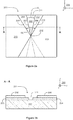
- Figure 1a shows a top view of an artifact 101 according to an exemplifying and non-limiting embodiment of the invention.
- Figure 1b shows a view of a section taken along a line A1-A1 shown in figure 1a
- figure 1c shows a view of a section taken along a line A2-A2 shown in figure 1a .
- the section plane is parallel with the yz-plane of a coordinate system 199.
- the section plane is parallel with the xz-plane of the coordinate system 199.
- the artifact 101 comprises a substrate 102 and layers 103 and 104 on top of the substrate.
- the layers 103 and 104 are stacked on each other in a partially overlapping way so that an edge 107 of the layer 103 is arranged to intersect with an edge 108 of the layer 104.
- the layer 103 is on the substrate 102, and the layer 104 is partially on the substrate 102 and partially on the layer 103.
- a part of the edge 107 which is covered by the layer 104 is depicted with a dashed line.
- the layers 103 and 104 together with the substrate 102 constitute a three-dimensional "3D" surface topography where a groove 111 defined by the above-mentioned edges 107 and 108 tapers towards the point of intersection 112 between the edges 107 and 108.
- the angle ⁇ 1 that is between the edges 107 and 108 and opens towards the groove 111 can be advantageously in the range from 5 degrees to 90 degrees, more advantageously in the range from 7 degrees to 20 degrees, and yet more advantageously in the range from 8 degrees to 12 degrees.
- the layers 103 and 104 comprise organic material in order to achieve a situation in which appropriate material properties of the artifact 101 are sufficiently close to appropriate material properties of biological or synthetic organic samples to be examined.
- the layers 103 and 104 are advantageously Langmuir-Blodgett films "LBF".
- the substrate 102 can be made of e.g. highly ordered pyrolytic graphite "HOPG", SiO 2 , metal, metal oxide, or silicon.
- Figure 2a shows a top view of an artifact 201 according to an exemplifying and non-limiting embodiment of the invention.
- Figure 2b shows a view of a section taken along a line A-A shown in figure 2a .
- the section plane is parallel with the xz-plane of a coordinate system 299.
- the artifact 201 comprises a substrate 202 and layers 203, 204, 205, and 206 on top of the substrate.
- the layers 203-204 are stacked on each other in a partially overlapping way so that edges 207, 208, 209, and 210 of the layers 203-206 are arranged to intersect with each other at a point of intersection 212 as illustrated in figure 2a .
- the first one of the layers 203 is on the substrate 202
- the second one of the layers 204 is partially on the substrate and partially on the layer 203
- the third one of the layers 205 is partially on the layer 203 and partially on the layer 204
- the fourth one of the layers 206 is partially on the layer 204 and partially on the layer 205.
- parts of the edges 207-209 which are covered by one or more of the layers 204-206 are depicted with dashed lines.
- the layers 203-206 together with the substrate 202 constitute a 3D surface topography where a groove 211 defined by the above-mentioned edges tapers towards the point of intersection 212 between the edges 207-210.
- the first angle ⁇ 1 that is between the edges 207 and 208 and opens towards the groove 211 is, when the artifact is seen along the direction perpendicular to the layers, inside the second angle ⁇ 2 that is between the edges 209 and 210 and opens towards the groove 211. Therefore, in the exemplifying artifact 201 illustrated in figures 2a and 2b , the groove 211 has a step-shaped cross-sectional profile as illustrated in figure 2b .
- the point of intersection between the edges 207 and 208 is, when seen along a direction perpendicular to the layers 203-206, substantially at a same location as the point of intersection between the edges 209 and 210. This is, however, not the only possible choice. It is, for example, also possible that the point of intersection between the edges 207 and 208 is, when seen along a direction perpendicular to the layers 203-206, at a different place than the point of intersection between the edges 209 and 210.
- Figure 3a shows a top view of an artifact 301 according to an exemplifying and non-limiting embodiment of the invention.
- Figure 3b shows a view of a section taken along a line A1-A1 shown in figure 3a
- figure 3c shows a view of a section taken along a line A2-A2 shown in figure 3a .
- the section plane is parallel with the yz-plane of a coordinate system 399.
- the section plane is parallel with the xz-plane of the coordinate system 399.
- the artifact 301 comprises a substrate 302 and layers 303, 304, 305, and 306 on top of the substrate.
- the layers 303-304 are stacked on each other in a partially overlapping way so that edges 307, 308, 309, and 310 of the layers 303-306 are arranged to intersect with each other at a point of intersection 312 as illustrated in figure 3a .
- the first one of the layers 303 is against the substrate 302
- the second one of the layers 304 is partially against the substrate and partially against the layer 303
- the third one of the layers 305 is partially against the layer 303 and partially against the layer 304
- the fourth one of the layers 306 is partially against the layer 304 and partially against the layer 305.
- the layers 303-306 together with the substrate 302 constitute a 3D surface topography where a groove 311 defined by the above-mentioned edges tapers towards the point of intersection 312 between the edges.
- the first angle ⁇ 1 that is between the edges 307 and 308 and opens towards the groove 311 is, when the artifact 301 is seen along the direction perpendicular to the layers, substantially coinciding with the second angle ⁇ 2 that is between the edges 309 and 310 and opens towards the groove 311. Therefore, in the exemplifying artifact 301 illustrated in figures 3a-3c , the depth of the groove 311 is increased by using more than two layers which are partially interleaved in the way illustrated in figure 3b .
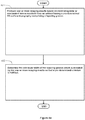
- FIG 4a shows a flowchart of a method according to an exemplifying and non-limiting embodiment of the invention for determining the resolution of imaging based on electromagnetic radiation and/or mechanical waves.
- the imaging can be, for example but not necessarily, interferometry based on interference between electromagnetic or mechanical waves reflected from an object being imaged and other electromagnetic or mechanical waves reflected from a reference reflector.
- the interferometry based on electromagnetic waves can e.g. be white-light interferometry "WLI”, white-light polarization interferometry "WLPI”, stroboscopic scanning white-light interferometry "SSWLI” and/or stroboscopic scanning white-light polarization interferometry "SSWLPI”.
- the imaging based on electromagnetic radiation can represent a low coherence technique, a confocal technique, a phase shifting technique, an ellipsometry imaging technique, and/or a surface plasmon resonance imaging "SPRi" technique.
- the interferometry based on mechanical waves can be e.g. acoustic interference microscopy.
- the imaging based on mechanical waves can be e.g. ultrasound imaging such as e.g. ultrasound microscopy. Imaging that is based on both electromagnetic radiation and mechanical waves can be for example laser-ultrasonic imaging where laser is used for exciting mechanical vibrations for imaging.
- the method comprises the following actions:
- the artifact can be, for example but not necessarily, such as the artifact 101 illustrated in figures 1a-1c , or the artifact 201 illustrated in figures 2a and 2b , or the artifact 301 illustrated in figures 3a-3c .
- the above-mentioned criterion can be for example a requirement that the one or more imaging results reveal at least a pre-determined portion of the depth of the above-mentioned tapering groove.
- Figure 4b illustrates the determination of the resolution of the imaging based on electromagnetic radiation and/or mechanical waves.
- the artifact is the artifact 101 illustrated in figures 1a-1c .
- Figure 4b shows the top view of the artifact 101 and views of sections taken along lines B1-B1, B2-B2, and B3-B3 shown in figure 4b .
- the section planes corresponding to sections B1-B1, B2-B2, and B3-B3 are parallel with the xz-plane of the coordinate system 199.
- the width of the tapering groove 111 in the section B1-B1 is denoted with W1
- the width of the tapering groove 111 in the section B2-B2 is denoted with W2
- the width of the tapering groove 111 in the section B3-B3 is denoted with W3.
- the depth of the tapering groove 111 is denoted with D.
- Dashed curves 414a, 414b, and 414c illustrate how the tapering groove 111 appears in the one or more imaging results based on the electromagnetic or mechanical waves received from the artifact 101.
- the dashed curve 414a illustrates that the one or more imaging results reveal 100% of the depth D of the tapering groove 111 when the width of the tapering groove is W1.
- the dashed curve 414b illustrates that the one or more imaging results reveal about 50% of the depth D of the tapering groove 111 when the width of the tapering groove is W2.
- the dashed curve 414c illustrates that the one or more imaging results reveal about 30% of the depth D of the tapering groove 111 when the width of the tapering groove is W3.
- the resolution of the imaging is W2.
- the resolution of the imaging is W3.
- FIG. 5 shows a flowchart of a method according to an exemplifying and non-limiting embodiment of the invention for calibrating imaging based on electromagnetic radiation and/or mechanical waves.
- the imaging can be, for example but not necessarily, interferometry based on interference between electromagnetic or mechanical waves reflected from an object being imaged and other electromagnetic or mechanical waves reflected from a reference reflector.
- the interferometry based on electromagnetic waves can e.g. be white-light interferometry "WLI”, white-light polarization interferometry "WLPI”, stroboscopic scanning white-light interferometry "SSWLI” and/or stroboscopic scanning white-light polarization interferometry "SSWLPI”.
- the imaging based on electromagnetic radiation can represent a low coherence technique, a confocal technique, a phase shifting technique, an ellipsometry imaging technique, and/or a surface plasmon resonance imaging "SPRi" technique.
- the interferometry based on mechanical waves can be e.g. acoustic interference microscopy.
- the imaging based on mechanical waves can be e.g. ultrasound imaging such as e.g. ultrasound microscopy. Imaging that is based on both electromagnetic radiation and mechanical waves can be for example laser-ultrasonic imaging where laser is used for exciting mechanical vibrations for imaging.
- the method comprises the following actions:
- the artifact can be, for example but not necessarily, such as the artifact 101 illustrated in figures 1a-1c , or the artifact 201 illustrated in figures 2a and 2b , or the artifact 301 illustrated in figures 3a-3c .
- At least a part of the sample and at least a part of the artifact are located in a field-of-view "FOV" of the imaging when the above-mentioned first and second electromagnetic or mechanical waves are received from the artifact and from the sample.
- the first and second electromagnetic or mechanical waves are received concurrently from the artifact and from the sample.
- Figure 6 shows a schematic illustration of a system according to an exemplifying and non-limiting embodiment of the invention for electromagnetic radiation-based three-dimensional "3D" imaging.
- the system comprises an artifact 601 that can be, for example but not necessarily, such as the artifact 101 illustrated in figures 1a-1c , or the artifact 201 illustrated in figures 2a and 2b , or the artifact 301 illustrated in figures 3a-3c .
- the system comprises an imaging device 615 for producing one or more first imaging results based on first electromagnetic waves received from the artifact 601 and for producing one or more second imaging result based on second electromagnetic waves received from a sample being imaged. The sample is not shown in figure 6 .
- a system comprises processing equipment 616 for determining the minimum width of the tapering groove of the artifact 601 which can be revealed by the above-mentioned one or more first imaging results so that a pre-determined criterion is fulfilled.
- the determined minimum width is indicative of the resolution of the electromagnetic radiation-based imaging.
- the criterion can be for example a requirement that the one or more first imaging results is/are capable of revealing at least a pre-determined portion of the depth of the tapering groove where the depth is measured in the z-direction of a coordinate system 699.
- a system comprises processing equipment 617 for calibrating the electromagnetic radiation-based imaging.
- the processing equipment 617 is configured to compare the above-mentioned one or more first imaging results to the known 3Dsurface topography of the artifact 601 so as to derive calibration data.
- the processing equipment 617 is configured to correct, with the aid of the derived calibration data, the above-mentioned one or more second imaging results to correspond to e.g. the surface relief of the imaged sample with a sufficient accuracy.
- the calibration data can be e.g. in the form of a lookup table and/or a correction equation with the aid of which the one or more second imaging results can be corrected.
- the imaging device 615 is an interferometer that comprises a light source 621, a dichroic mirror 622, a reference reflector 620, and an imaging sensor 623 that can be e.g. a charge-coupled device "CCD" sensor. Furthermore, the imaging device 615 comprises lenses for focusing and collimating light in desired ways. In cases where the calibration artifact 601 and samples to be imaged are immersed in liquid e.g. immersion oil, the imaging device 615 comprises advantageously the Michelson or Linnik compensation arrangement for compensating imaging errors that would be otherwise caused by the immersing.
- Imaging in the z-direction of the coordinate system 699 is based on the interference between electromagnetic waves reflected from the calibration artifact 601 and other electromagnetic waves reflected from the reference reflector 620.
- the propagation of the electromagnetic waves reflected from the calibration artifact 601 is depicted with lines 624 and the propagation of the electromagnetic waves reflected from the reference reflector 620 is depicted with dashed lines 625.
- the interferometer can be e.g. a white-light interferometer "WLI", a white-light polarization interferometer "WPLI”, and/or a stroboscopic scanning white-light interferometer "SSWLI".
- the processing equipment 616 and the processing equipment 617 shown in figure 6 can be implemented with one or more processor circuits, each of which can be a programmable processor circuit provided with appropriate software, a dedicated hardware processor such as, for example, an application specific integrated circuit "ASIC”, or a configurable hardware processor such as, for example, a field programmable gate array "FPGA”.
- processor circuits each of which can be a programmable processor circuit provided with appropriate software, a dedicated hardware processor such as, for example, an application specific integrated circuit "ASIC”, or a configurable hardware processor such as, for example, a field programmable gate array "FPGA”.
- ASIC application specific integrated circuit
- FPGA field programmable gate array
- Figure 7 illustrates a part of a system according to an exemplifying and non-limiting embodiment of the invention for electromagnetic radiation-based imaging.
- An imaging device of the system is not shown in figure 7 .
- the imaging device can be for example such as the imaging device 615 illustrated in figure 6 .
- the imaging device is configured to produce one or more first imaging results based on first electromagnetic waves received from an artifact 701 and one or more second imaging results based on second electromagnetic waves received from a sample 718 to be imaged.
- the artifact 701 can be, for example but not necessarily, such as the artifact 101 illustrated in figures 1a-1c , or the artifact 201 illustrated in figures 2a and 2b , or the artifact 301 illustrated in figures 3a-3c .
- the imaging device is configured to produce the one or more first imaging results and the one or more second imaging results in a situation in which the artifact 701 and the sample 718 are located adjacent to each other as illustrated in figure 7 . Therefore, the artifact 701 and the sample 718 do not need to be moved with respect to each other when producing the one or more first imaging results related to the artifact 701 and the one or more second imaging results related to the sample 718.
- the production circumstances of the one or more first imaging results correspond in a reliable way to the production circumstances of the one or more second imaging results. This improves the accuracy when the one or more first imaging results related to the artifact 701 are used for correcting the one or more second imaging results related to the sample 718, i.e.
- the calibration accuracy is improved.
- the electromagnetic waves propagating towards the artifact 701 and the sample 718 are depicted with dash-and-dot line wavy arrows
- the electromagnetic waves reflected from the artifact 701 are depicted with solid line wavy arrows
- the electromagnetic waves reflected from sample 718 are depicted with dashed line wavy arrows.
- At least a part of the sample 718 and at least a part of the artifact 701 are located concurrently in the field-of-view "FOV" 719 of the imaging device.
- the one or more first imaging results related to the artifact 701 and the one or more second imaging results related to the sample 718 belong to a same image, which improves the calibration accuracy.
- This approach provides instantaneous calibration which is advantageous especially in cases where a large stitched image is constructed so that the field-of-view "FOV" 719 of the imaging device is moving with respect to the sample 718 and the artifact 701.
- the system can be provided with many artifacts in order to provide appropriate calibration in different positions of the field-of-view "FOV" 719.
- there is another artifact 751 and the FOV 719 is moving in the positive y-direction of a coordinate system 799.
- the FOV movement is depicted with an arrow 752.
- Figure 8 illustrates a part of a system according to an exemplifying and non-limiting embodiment of the invention for electromagnetic radiation-based imaging.
- the system is configured to carry out the electromagnetic radiation-based imaging for many samples one by one.
- six of the samples are denoted with figure references 818a, 818b, 818c, 818d, 818e, and 818f.
- the samples are moved in the positive x-direction of a coordinate system 899 with the aid of a conveyance device 850.
- the conveyance device 850 is a conveyor belt. This is, however, not the only possible choice.
- each of the samples is in its turn in the field-of-view "FOV" 819 of an imaging device of the system.
- the imaging device is not shown in figure 8 .
- the imaging device can be for example such as the imaging device 615 illustrated in figure 6 .
- the sample 818d is in the field-of-view "FOV" 819.
- the system comprises an artifact 801 that is also in the field-of-view "FOV" 819 of the imaging device. As the sample under consideration and the artifact 801 belong to a same image, accurate imaging can be achieved.
- the artifact 801 can be, for example but not necessarily, such as the artifact 101 illustrated in figures 1a-1c , or the artifact 201 illustrated in figures 2a and 2b , or the artifact 301 illustrated in figures 3a-3c .
- Figures 6 , 7, and 8 illustrate exemplifying systems for electromagnetic radiation-based imaging.
- a system according to an exemplifying and non-limiting embodiment of the invention for mechanical wave-based imaging comprises:
- the artifact can be, for example but not necessarily, such as the artifact 101 illustrated in figures 1a-1c , or the artifact 201 illustrated in figures 2a and 2b , or the artifact 301 illustrated in figures 3a-3c .
- the imaging device can be e.g. an ultrasound imaging device e.g. an ultrasound microscope.
- the imaging device can be e.g. interferometer based on mechanical waves, e.g. an acoustic interference microscope.
- the pre-determined criterion can be e.g. a requirement that the one or more imaging results reveal at least a pre-determined portion of a depth of the tapering groove.
- the imaging device is configured to produce the one or more first imaging results and to produce the one or more second imaging results in a situation in which at least a part of the sample and at least a part of the artifact are located in a field-of-view of the imaging.
- the imaging device is configured to receive the first and second mechanical waves concurrently from the artifact and from the sample.
Landscapes
- Physics & Mathematics (AREA)
- General Physics & Mathematics (AREA)
- Engineering & Computer Science (AREA)
- Remote Sensing (AREA)
- Radar, Positioning & Navigation (AREA)
- Analytical Chemistry (AREA)
- Chemical & Material Sciences (AREA)
- Acoustics & Sound (AREA)
- Computer Networks & Wireless Communication (AREA)
- Theoretical Computer Science (AREA)
- Pathology (AREA)
- Health & Medical Sciences (AREA)
- Life Sciences & Earth Sciences (AREA)
- Biochemistry (AREA)
- General Health & Medical Sciences (AREA)
- Immunology (AREA)
- Computer Vision & Pattern Recognition (AREA)
- Optics & Photonics (AREA)
- Mathematical Physics (AREA)
- Spectroscopy & Molecular Physics (AREA)
- Geometry (AREA)
- Length Measuring Devices By Optical Means (AREA)
- Investigating Or Analysing Materials By Optical Means (AREA)
Claims (15)
- Artefakt (101, 201, 301, 601, 701) zum Bestimmen einer Bildgebungsauflösung basierend auf elektromagnetischer Strahlung, mechanischer Wellen oder sowohl elektromagnetischer Strahlung als auch mechanischer Wellen, wobei das Artefakt umfasst:- ein Substrat (102, 202, 302) und- Schichten (103, 104, 203-206, 303-306) oben auf dem Substrat,dadurch gekennzeichnet, dass die Schichten organisches Material umfassen und mindestens zwei der Schichten in einer teilweise überlappenden Weise derart aufeinander gestapelt sind, dass eine Kante (107, 207) einer ersten der Schichten angeordnet ist, um eine Kante (108, 208) einer zweiten der Schichten zu schneiden, wobei die Schichten eine dreidimensionale Oberflächentopografie bilden, in welcher, wenn das Artefakt entlang einer Richtung senkrecht zu den Schnittstelle betrachtet wird, sich eine durch die Kanten der ersten und zweiten der Schichten definierte Nut (111, 211, 311) hin zu einem Schnittpunkt (112, 212, 312) zwischen den Kanten verjüngt.
- Artefakt nach Anspruch 1, wobei jede der Schichten ein Langmuir-Blodgett-Film ist.
- Artefakt nach Anspruch 1 oder 2, wobei das Substrat aus hochgeordnetem pyrolytischem Graphitsubstrat hergestellt ist.
- Artefakt nach einem der Ansprüche 1-3, wobei die erste der Schichten auf dem Substrat mit dem Substrat in Kontakt ist, wobei die zweite der Schichten teilweise auf dem Substrat mit dem Substrat in Kontakt ist und teilweise auf der ersten der Schichten mit der ersten der Schichten in Kontakt ist und wobei ein Winkel (α1) zwischen den Kanten und hin zu der Nut (111) öffnend in dem Bereich von 5 Grad bis 90 Grad liegt.
- Artefakt nach einem der Ansprüche 1-3, wobei die erste der Schichten (203, 303) auf dem Substrat mit dem Substrat in Kontakt ist, wobei die zweite der Schichten (204, 304) teilweise auf dem Substrat mit dem Substrat in Kontakt ist und teilweise auf der ersten der Schichten mit der ersten der Schichten in Kontakt ist, wobei eine dritte der Schichten (205, 305) teilweise auf der ersten der Schichten mit der ersten der Schichten in Kontakt ist und teilweise auf der zweiten der Schichten mit der zweiten der Schichten in Kontakt ist und wobei eine vierte der Schichten (206, 306) teilweise auf der zweiten der Schichten mit der zweiten der Schichten in Kontakt ist und teilweise gegen die dritte der Schichten mit der dritten der Schichten in Kontakt ist.
- Artefakt nach Anspruch 5, wobei ein erster Winkel (α1) zwischen den Kanten (207, 208) der ersten und zweiten der Schichten und hin zu der Nut (211) öffnend, wenn das Artefakt entlang der Richtung senkrecht zu den Schichten betrachtet wird, innerhalb eines zweiten Winkels (α2) zwischen Kanten (209, 210) der dritten und vierten der Schichten und hin zu der Nut (211) öffnend liegt.
- Artefakt nach Anspruch 5 oder 6, wobei sich der Schnittpunkt (212, 312) zwischen den Kanten (207, 208, 307, 308) der ersten und zweiten der Schichten, wenn das Artefakt entlang der Richtung senkrecht zu den Schichten betrachtet wird, im Wesentlichen an der gleichen Stelle wie ein Schnittpunkt zwischen Kanten (209, 210, 309, 310) der dritten und vierten der Schichten befindet.
- Artefakt nach Anspruch 5, wobei ein erster Winkel (α1) zwischen den Kanten (307, 308) der ersten und zweiten der Schichten und hin zu der Nut (311) öffnend, wenn das Artefakt entlang der Richtung senkrecht zu den Schichten betrachtet wird, im Wesentlichen mit einem zweiten Winkel (α2) zwischen Kanten (309, 310) der dritten und vierten der Schichten und hin zu der Nut (311) öffnend übereinstimmt.
- Verfahren zum Bestimmen einer Bildgebungsauflösung basierend auf elektromagnetischer Strahlung, mechanischer Wellen oder sowohl elektromagnetischer Strahlung als auch mechanischer Wellen, wobei das Verfahren umfasst:- Erzeugen (451) eines oder mehrerer Bildgebungsergebnisse basierend auf elektromagnetischen oder mechanischen Wellen, die von dem Artefakt nach einem der Ansprüche 1-8 empfangen werden, wobei das Artefakt eine vorbestimmte dreidimensionale Oberflächentopografie aufweist, welche eine sich verjüngende Nut umfasst, und- Bestimmen (452) einer minimalen Breite der sich verjüngenden Nut, die durch das eine oder die mehreren Bildgebungsergebnisse aufgezeigt wird, sodass ein vorbestimmtes Kriterium erfüllt ist, wobei die bestimmte minimale Breite die Bildgebungsauflösung angibt.
- Verfahren nach Anspruch 9, wobei das vorbestimmte Kriterium ist, dass das eine oder die mehreren Bildgebungsergebnisse mindestens einen vorbestimmten Abschnitt einer Tiefe der sich verjüngenden Nut aufzeigen.
- Verfahren zum Kalibrieren einer Bildgebung basierend auf elektromagnetischer Strahlung, mechanischer Wellen oder sowohl elektromagnetischer Strahlung als auch mechanischer Wellen, wobei das Verfahren umfasst:- Erzeugen (501) eines oder mehrerer erster Bildgebungsergebnisse basierend auf ersten elektromagnetischen oder mechanischen Wellen, die von dem Artefakt nach einem der Ansprüche 1-8 empfangen werden, wobei das Artefakt eine vorbestimmte dreidimensionale Oberflächentopografie aufweist,- Bilden (502) von Kalibrierungsdaten basierend auf dem einen oder den mehreren ersten Bildgebungsergebnissen und der vorbestimmten dreidimensionalen Oberflächentopografie des Artefakts, und- Korrigieren (503) mithilfe der Kalibrierungsdaten eines oder mehrerer zweiter Bildgebungsergebnisse, welche basierend auf zweiten elektromagnetischen oder mechanischen Wellen erzeugt werden, die von einer abzubildenden Probe empfangen werden.
- Verfahren nach Anspruch 11, wobei sich mindestens ein Teil der Probe und mindestens ein Teil des Artefakts in einem Sichtfeld der Bildgebung befinden, wenn die ersten und zweiten elektromagnetischen oder mechanischen Wellen von dem Artefakt und von der Probe empfangen werden.
- Verfahren nach Anspruch 12, wobei die ersten und zweiten elektromagnetischen oder mechanischen Wellen von dem Artefakt und von der Probe gleichzeitig empfangen werden.
- System zur Bildgebung basierend auf elektromagnetischer Strahlung, mechanischer Wellen oder sowohl elektromagnetischer Strahlung als auch mechanischer Wellen, wobei das System umfasst:- ein Artefakt (601, 701, 801) nach einem der Ansprüche 1-8, wobei das Artefakt eine vorbestimmte dreidimensionale Oberflächentopografie aufweist, welche eine sich verjüngende Nut umfasst, und- eine Bildgebungsvorrichtung (615) zum Erzeugen eines oder mehrerer erster Bildgebungsergebnisse basierend auf ersten elektromagnetischen oder mechanischen Wellen, die von dem Artefakt empfangen werden, und zum Erzeugen eines oder mehrerer Bildgebungsergebnisse basierend auf zweiten elektromagnetischen oder mechanischen Wellen, die von einer abzubildenden Probe (718, 818a-818f) empfangen werden.
- System nach Anspruch 14, wobei das System Verarbeitungsausrüstung (617) umfasst zum:- Bilden von Kalibrierungsdaten basierend auf dem einen oder den mehreren ersten Bildgebungsergebnissen und der vorbestimmten dreidimensionalen Oberflächentopografie des Artefakts, und- Korrigieren mithilfe der Kalibrierungsdaten des einen oder der mehreren zweiten Bildgebungsergebnisse.
Applications Claiming Priority (2)
| Application Number | Priority Date | Filing Date | Title |
|---|---|---|---|
| FI20165400A FI127463B (en) | 2016-05-10 | 2016-05-10 | An artifact for determining resolution of imaging based on electromagnetic radiation and/or mechanical waves |
| PCT/FI2017/050353 WO2017194832A1 (en) | 2016-05-10 | 2017-05-08 | An artifact for determining resolution of imaging based on electromagnetic radiation and/or mechanical waves |
Publications (2)
| Publication Number | Publication Date |
|---|---|
| EP3455583A1 EP3455583A1 (de) | 2019-03-20 |
| EP3455583B1 true EP3455583B1 (de) | 2020-12-30 |
Family
ID=59055228
Family Applications (1)
| Application Number | Title | Priority Date | Filing Date |
|---|---|---|---|
| EP17729908.8A Not-in-force EP3455583B1 (de) | 2016-05-10 | 2017-05-08 | Artefakt zur bestimmung der auflösung der bildgebung auf der basis von elektromagnetischer strahlung und/oder mechanischen wellen |
Country Status (8)
| Country | Link |
|---|---|
| US (1) | US10839558B2 (de) |
| EP (1) | EP3455583B1 (de) |
| JP (1) | JP2019515306A (de) |
| CN (1) | CN109073358A (de) |
| CA (1) | CA3022161A1 (de) |
| ES (1) | ES2859109T3 (de) |
| FI (1) | FI127463B (de) |
| WO (1) | WO2017194832A1 (de) |
Families Citing this family (4)
| Publication number | Priority date | Publication date | Assignee | Title |
|---|---|---|---|---|
| FI20176026A1 (en) * | 2017-11-16 | 2019-05-17 | Helsingin Yliopisto | Artifact for assisting imaging based on electromagnetic radiation and / or mechanical waves and method of making it |
| CN108398489B (zh) * | 2018-01-04 | 2020-10-30 | 北京科技大学 | 一种精确测量聚焦超声换能器横向分辨率的方法 |
| CN109870416B (zh) * | 2019-01-22 | 2021-10-01 | 华灿光电(浙江)有限公司 | 石墨盘检测方法和装置 |
| CN112578024B (zh) * | 2020-11-26 | 2022-01-25 | 北京理工大学 | 超声c扫描检测分辨力的计算方法、测量装置和测量方法 |
Family Cites Families (16)
| Publication number | Priority date | Publication date | Assignee | Title |
|---|---|---|---|---|
| US2536401A (en) * | 1944-09-14 | 1951-01-02 | Victor Victor | Gauge block |
| US4582427A (en) | 1983-10-13 | 1986-04-15 | The United States Of America As Represented By The Secretary Of The Air Force | Test target for adaptive optics |
| US4818725A (en) * | 1986-09-15 | 1989-04-04 | Harris Corp. | Technique for forming planarized gate structure |
| FR2703448B1 (fr) | 1993-03-31 | 1995-06-23 | Attm | Standard de calibration. |
| JP4060365B2 (ja) * | 1996-09-05 | 2008-03-12 | ルドルフ シュヴァルト | 電磁波の位相情報および/または振幅情報を調べるための方法と装置 |
| KR100278561B1 (ko) * | 1996-10-15 | 2001-02-01 | 포만 제프리 엘 | 테이퍼를구비하며에칭성이감소된다층의금속샌드위치구조및그형성방법 |
| US6490033B1 (en) * | 2000-01-05 | 2002-12-03 | Lucent Technologies Inc. | Method of thin film process control and calibration standard for optical profilometry step height measurement |
| US7262842B2 (en) | 2001-03-28 | 2007-08-28 | Clondiag Chip Technologies Gmbh | Device for referencing fluorescence signals |
| US20040005243A1 (en) | 2002-03-06 | 2004-01-08 | Gregory Mulhern | Patterned supports for testing, evaluating and calibrating detection devices |
| JP4400117B2 (ja) | 2003-07-10 | 2010-01-20 | 株式会社ニコン | Euv露光方法における解像力の判定方法及びeuv露光装置 |
| DE10356829B3 (de) | 2003-12-05 | 2005-08-18 | Robert Bosch Gmbh | Messnormal für interferometrische Systeme |
| DE102005049364B4 (de) | 2005-03-18 | 2023-05-25 | BAM Bundesanstalt für Materialforschung und -prüfung | Multifunktionelle Kalibriereinrichtung und Kit sowie ihre Verwendungen zur Charakterisierung von Lumineszenzmesssystemen |
| AU2008276127A1 (en) | 2007-07-17 | 2009-01-22 | Hach Company | Spatial frequency optical measurement instrument and method |
| GB201202557D0 (en) * | 2012-02-15 | 2012-03-28 | Renishaw Plc | A gauge artefact and method for checking a coordinate positioning machine |
| KR102236460B1 (ko) * | 2014-10-31 | 2021-04-06 | 엘지디스플레이 주식회사 | 인셀 터치 액정 표시 장치와 이의 제조 방법, 박막트랜지스터 어레이 기판의 제조 방법 및 컬러필터 어레이 기판의 제조 방법 |
| CN104777239A (zh) | 2015-04-10 | 2015-07-15 | 上海和伍新材料科技有限公司 | 一种低压电器电触头超声波探伤用台阶型测试工件 |
-
2016
- 2016-05-10 FI FI20165400A patent/FI127463B/en active
-
2017
- 2017-05-08 JP JP2018559884A patent/JP2019515306A/ja active Pending
- 2017-05-08 ES ES17729908T patent/ES2859109T3/es active Active
- 2017-05-08 CN CN201780028380.1A patent/CN109073358A/zh active Pending
- 2017-05-08 CA CA3022161A patent/CA3022161A1/en active Pending
- 2017-05-08 WO PCT/FI2017/050353 patent/WO2017194832A1/en not_active Ceased
- 2017-05-08 US US16/301,279 patent/US10839558B2/en not_active Expired - Fee Related
- 2017-05-08 EP EP17729908.8A patent/EP3455583B1/de not_active Not-in-force
Non-Patent Citations (1)
| Title |
|---|
| None * |
Also Published As
| Publication number | Publication date |
|---|---|
| FI127463B (en) | 2018-06-29 |
| WO2017194832A1 (en) | 2017-11-16 |
| FI20165400A7 (fi) | 2017-11-11 |
| US20200320741A1 (en) | 2020-10-08 |
| EP3455583A1 (de) | 2019-03-20 |
| ES2859109T3 (es) | 2021-10-01 |
| CA3022161A1 (en) | 2017-11-16 |
| US10839558B2 (en) | 2020-11-17 |
| CN109073358A (zh) | 2018-12-21 |
| JP2019515306A (ja) | 2019-06-06 |
Similar Documents
| Publication | Publication Date | Title |
|---|---|---|
| US10839558B2 (en) | Artifact for determining resolution of imaging based on electromagnetic radiation and/or mechanical waves | |
| CN107407798B (zh) | 通过低相干干涉法自动聚焦调节的显微镜系统 | |
| Schmit et al. | High-precision shape measurement by white-light interferometry with real-time scanner error correction | |
| WO2006137448A1 (ja) | 試料膨張・収縮量計測システムおよび試料膨張・収縮量計測方法 | |
| US10234266B2 (en) | Method for calibrating 3D imaging and system for 3D imaging | |
| JP2014098690A (ja) | 校正装置、校正方法及び計測装置 | |
| WO2019097118A1 (en) | An artifact for assisting imaging based on electromagnetic radiation and/or mechanical waves and a method for manufacturing the same | |
| Tan et al. | Calibrate the non-orthogonal error of AFM with two-dimensional self-traceable grating | |
| CN107796326B (zh) | 使用了扫描型白色干涉显微镜的三维形状计测方法 | |
| Huebner et al. | A nanoscale linewidth/pitch standard for high-resolution optical microscopy and other microscopic techniques | |
| US11965730B2 (en) | Method for measuring film thickness distribution of wafer with thin films | |
| JP2016511829A (ja) | 領域の表面精度の定量的測定のための方法及び装置 | |
| WO2005116716A1 (en) | A means for calibrating a microscope, a method of preparing the means and a method of calibrating a microscope | |
| Bermudez et al. | Round robin test on V-shape bio-imaging transfer standard for determination of the instrument transfer function of 3D optical profilers | |
| Piano et al. | Micro-scale geometry measurement | |
| FI129478B (en) | Method and system for radiation-based imaging | |
| US20190323820A1 (en) | An artifact for improving vertical resolution of radiation-based imaging | |
| Hongo et al. | Development of Scanning Laser Interferometer with wide field of view-Measurement of small lens mold | |
| RU2462726C2 (ru) | Способ сканирования на сканирующем зондовом микроскопе и формирования изображения поверхности | |
| Wang et al. | Surface profile measurement by using the integrated Linnik WLSI and confocal microscope system | |
| Costa et al. | Assessment of residual stress on thin films by laser microtopography | |
| Stürwald et al. | Combination of a nano-coordinate measuring machine with a low-coherent digital holographic microscopy sensor for large-scale measurements | |
| Shimizu et al. | Surface characterization of a diamond turned XY sinusoidal grating |
Legal Events
| Date | Code | Title | Description |
|---|---|---|---|
| STAA | Information on the status of an ep patent application or granted ep patent |
Free format text: STATUS: UNKNOWN |
|
| STAA | Information on the status of an ep patent application or granted ep patent |
Free format text: STATUS: THE INTERNATIONAL PUBLICATION HAS BEEN MADE |
|
| PUAI | Public reference made under article 153(3) epc to a published international application that has entered the european phase |
Free format text: ORIGINAL CODE: 0009012 |
|
| STAA | Information on the status of an ep patent application or granted ep patent |
Free format text: STATUS: REQUEST FOR EXAMINATION WAS MADE |
|
| 17P | Request for examination filed |
Effective date: 20181019 |
|
| AK | Designated contracting states |
Kind code of ref document: A1 Designated state(s): AL AT BE BG CH CY CZ DE DK EE ES FI FR GB GR HR HU IE IS IT LI LT LU LV MC MK MT NL NO PL PT RO RS SE SI SK SM TR |
|
| AX | Request for extension of the european patent |
Extension state: BA ME |
|
| RAP1 | Party data changed (applicant data changed or rights of an application transferred) |
Owner name: NANOJET OY |
|
| DAV | Request for validation of the european patent (deleted) | ||
| DAX | Request for extension of the european patent (deleted) | ||
| GRAP | Despatch of communication of intention to grant a patent |
Free format text: ORIGINAL CODE: EPIDOSNIGR1 |
|
| STAA | Information on the status of an ep patent application or granted ep patent |
Free format text: STATUS: GRANT OF PATENT IS INTENDED |
|
| INTG | Intention to grant announced |
Effective date: 20191219 |
|
| REG | Reference to a national code |
Ref country code: HK Ref legal event code: DE Ref document number: 40006313 Country of ref document: HK |
|
| GRAS | Grant fee paid |
Free format text: ORIGINAL CODE: EPIDOSNIGR3 |
|
| 19U | Interruption of proceedings before grant |
Effective date: 20200224 |
|
| 19W | Proceedings resumed before grant after interruption of proceedings |
Effective date: 20201102 |
|
| GRAA | (expected) grant |
Free format text: ORIGINAL CODE: 0009210 |
|
| STAA | Information on the status of an ep patent application or granted ep patent |
Free format text: STATUS: THE PATENT HAS BEEN GRANTED |
|
| RAP1 | Party data changed (applicant data changed or rights of an application transferred) |
Owner name: NANOFORM FINLAND OYJ |
|
| AK | Designated contracting states |
Kind code of ref document: B1 Designated state(s): AL AT BE BG CH CY CZ DE DK EE ES FI FR GB GR HR HU IE IS IT LI LT LU LV MC MK MT NL NO PL PT RO RS SE SI SK SM TR |
|
| REG | Reference to a national code |
Ref country code: GB Ref legal event code: FG4D |
|
| REG | Reference to a national code |
Ref country code: AT Ref legal event code: REF Ref document number: 1350368 Country of ref document: AT Kind code of ref document: T Effective date: 20210115 |
|
| REG | Reference to a national code |
Ref country code: DE Ref legal event code: R096 Ref document number: 602017030456 Country of ref document: DE |
|
| REG | Reference to a national code |
Ref country code: IE Ref legal event code: FG4D |
|
| PG25 | Lapsed in a contracting state [announced via postgrant information from national office to epo] |
Ref country code: FI Free format text: LAPSE BECAUSE OF FAILURE TO SUBMIT A TRANSLATION OF THE DESCRIPTION OR TO PAY THE FEE WITHIN THE PRESCRIBED TIME-LIMIT Effective date: 20201230 Ref country code: GR Free format text: LAPSE BECAUSE OF FAILURE TO SUBMIT A TRANSLATION OF THE DESCRIPTION OR TO PAY THE FEE WITHIN THE PRESCRIBED TIME-LIMIT Effective date: 20210331 Ref country code: NO Free format text: LAPSE BECAUSE OF FAILURE TO SUBMIT A TRANSLATION OF THE DESCRIPTION OR TO PAY THE FEE WITHIN THE PRESCRIBED TIME-LIMIT Effective date: 20210330 Ref country code: RS Free format text: LAPSE BECAUSE OF FAILURE TO SUBMIT A TRANSLATION OF THE DESCRIPTION OR TO PAY THE FEE WITHIN THE PRESCRIBED TIME-LIMIT Effective date: 20201230 |
|
| REG | Reference to a national code |
Ref country code: AT Ref legal event code: MK05 Ref document number: 1350368 Country of ref document: AT Kind code of ref document: T Effective date: 20201230 |
|
| PG25 | Lapsed in a contracting state [announced via postgrant information from national office to epo] |
Ref country code: SE Free format text: LAPSE BECAUSE OF FAILURE TO SUBMIT A TRANSLATION OF THE DESCRIPTION OR TO PAY THE FEE WITHIN THE PRESCRIBED TIME-LIMIT Effective date: 20201230 Ref country code: LV Free format text: LAPSE BECAUSE OF FAILURE TO SUBMIT A TRANSLATION OF THE DESCRIPTION OR TO PAY THE FEE WITHIN THE PRESCRIBED TIME-LIMIT Effective date: 20201230 Ref country code: BG Free format text: LAPSE BECAUSE OF FAILURE TO SUBMIT A TRANSLATION OF THE DESCRIPTION OR TO PAY THE FEE WITHIN THE PRESCRIBED TIME-LIMIT Effective date: 20210330 |
|
| REG | Reference to a national code |
Ref country code: NL Ref legal event code: MP Effective date: 20201230 |
|
| PG25 | Lapsed in a contracting state [announced via postgrant information from national office to epo] |
Ref country code: HR Free format text: LAPSE BECAUSE OF FAILURE TO SUBMIT A TRANSLATION OF THE DESCRIPTION OR TO PAY THE FEE WITHIN THE PRESCRIBED TIME-LIMIT Effective date: 20201230 |
|
| REG | Reference to a national code |
Ref country code: LT Ref legal event code: MG9D |
|
| PG25 | Lapsed in a contracting state [announced via postgrant information from national office to epo] |
Ref country code: CZ Free format text: LAPSE BECAUSE OF FAILURE TO SUBMIT A TRANSLATION OF THE DESCRIPTION OR TO PAY THE FEE WITHIN THE PRESCRIBED TIME-LIMIT Effective date: 20201230 Ref country code: EE Free format text: LAPSE BECAUSE OF FAILURE TO SUBMIT A TRANSLATION OF THE DESCRIPTION OR TO PAY THE FEE WITHIN THE PRESCRIBED TIME-LIMIT Effective date: 20201230 Ref country code: LT Free format text: LAPSE BECAUSE OF FAILURE TO SUBMIT A TRANSLATION OF THE DESCRIPTION OR TO PAY THE FEE WITHIN THE PRESCRIBED TIME-LIMIT Effective date: 20201230 Ref country code: PT Free format text: LAPSE BECAUSE OF FAILURE TO SUBMIT A TRANSLATION OF THE DESCRIPTION OR TO PAY THE FEE WITHIN THE PRESCRIBED TIME-LIMIT Effective date: 20210430 Ref country code: SK Free format text: LAPSE BECAUSE OF FAILURE TO SUBMIT A TRANSLATION OF THE DESCRIPTION OR TO PAY THE FEE WITHIN THE PRESCRIBED TIME-LIMIT Effective date: 20201230 Ref country code: RO Free format text: LAPSE BECAUSE OF FAILURE TO SUBMIT A TRANSLATION OF THE DESCRIPTION OR TO PAY THE FEE WITHIN THE PRESCRIBED TIME-LIMIT Effective date: 20201230 |
|
| PG25 | Lapsed in a contracting state [announced via postgrant information from national office to epo] |
Ref country code: AT Free format text: LAPSE BECAUSE OF FAILURE TO SUBMIT A TRANSLATION OF THE DESCRIPTION OR TO PAY THE FEE WITHIN THE PRESCRIBED TIME-LIMIT Effective date: 20201230 Ref country code: PL Free format text: LAPSE BECAUSE OF FAILURE TO SUBMIT A TRANSLATION OF THE DESCRIPTION OR TO PAY THE FEE WITHIN THE PRESCRIBED TIME-LIMIT Effective date: 20201230 |
|
| PG25 | Lapsed in a contracting state [announced via postgrant information from national office to epo] |
Ref country code: IS Free format text: LAPSE BECAUSE OF FAILURE TO SUBMIT A TRANSLATION OF THE DESCRIPTION OR TO PAY THE FEE WITHIN THE PRESCRIBED TIME-LIMIT Effective date: 20210430 |
|
| REG | Reference to a national code |
Ref country code: DE Ref legal event code: R097 Ref document number: 602017030456 Country of ref document: DE Ref country code: ES Ref legal event code: FG2A Ref document number: 2859109 Country of ref document: ES Kind code of ref document: T3 Effective date: 20211001 |
|
| PG25 | Lapsed in a contracting state [announced via postgrant information from national office to epo] |
Ref country code: AL Free format text: LAPSE BECAUSE OF FAILURE TO SUBMIT A TRANSLATION OF THE DESCRIPTION OR TO PAY THE FEE WITHIN THE PRESCRIBED TIME-LIMIT Effective date: 20201230 Ref country code: IT Free format text: LAPSE BECAUSE OF FAILURE TO SUBMIT A TRANSLATION OF THE DESCRIPTION OR TO PAY THE FEE WITHIN THE PRESCRIBED TIME-LIMIT Effective date: 20201230 |
|
| PLBE | No opposition filed within time limit |
Free format text: ORIGINAL CODE: 0009261 |
|
| STAA | Information on the status of an ep patent application or granted ep patent |
Free format text: STATUS: NO OPPOSITION FILED WITHIN TIME LIMIT |
|
| PG25 | Lapsed in a contracting state [announced via postgrant information from national office to epo] |
Ref country code: DK Free format text: LAPSE BECAUSE OF FAILURE TO SUBMIT A TRANSLATION OF THE DESCRIPTION OR TO PAY THE FEE WITHIN THE PRESCRIBED TIME-LIMIT Effective date: 20201230 |
|
| 26N | No opposition filed |
Effective date: 20211001 |
|
| REG | Reference to a national code |
Ref country code: CH Ref legal event code: PL |
|
| PG25 | Lapsed in a contracting state [announced via postgrant information from national office to epo] |
Ref country code: CH Free format text: LAPSE BECAUSE OF NON-PAYMENT OF DUE FEES Effective date: 20210531 Ref country code: MC Free format text: LAPSE BECAUSE OF FAILURE TO SUBMIT A TRANSLATION OF THE DESCRIPTION OR TO PAY THE FEE WITHIN THE PRESCRIBED TIME-LIMIT Effective date: 20201230 Ref country code: LI Free format text: LAPSE BECAUSE OF NON-PAYMENT OF DUE FEES Effective date: 20210531 Ref country code: LU Free format text: LAPSE BECAUSE OF NON-PAYMENT OF DUE FEES Effective date: 20210508 |
|
| REG | Reference to a national code |
Ref country code: BE Ref legal event code: MM Effective date: 20210531 |
|
| PG25 | Lapsed in a contracting state [announced via postgrant information from national office to epo] |
Ref country code: SI Free format text: LAPSE BECAUSE OF FAILURE TO SUBMIT A TRANSLATION OF THE DESCRIPTION OR TO PAY THE FEE WITHIN THE PRESCRIBED TIME-LIMIT Effective date: 20201230 |
|
| PG25 | Lapsed in a contracting state [announced via postgrant information from national office to epo] |
Ref country code: IE Free format text: LAPSE BECAUSE OF NON-PAYMENT OF DUE FEES Effective date: 20210508 |
|
| PG25 | Lapsed in a contracting state [announced via postgrant information from national office to epo] |
Ref country code: IS Free format text: LAPSE BECAUSE OF FAILURE TO SUBMIT A TRANSLATION OF THE DESCRIPTION OR TO PAY THE FEE WITHIN THE PRESCRIBED TIME-LIMIT Effective date: 20210430 |
|
| PG25 | Lapsed in a contracting state [announced via postgrant information from national office to epo] |
Ref country code: BE Free format text: LAPSE BECAUSE OF NON-PAYMENT OF DUE FEES Effective date: 20210531 |
|
| PG25 | Lapsed in a contracting state [announced via postgrant information from national office to epo] |
Ref country code: NL Free format text: LAPSE BECAUSE OF NON-PAYMENT OF DUE FEES Effective date: 20201230 Ref country code: CY Free format text: LAPSE BECAUSE OF FAILURE TO SUBMIT A TRANSLATION OF THE DESCRIPTION OR TO PAY THE FEE WITHIN THE PRESCRIBED TIME-LIMIT Effective date: 20201230 |
|
| PG25 | Lapsed in a contracting state [announced via postgrant information from national office to epo] |
Ref country code: SM Free format text: LAPSE BECAUSE OF FAILURE TO SUBMIT A TRANSLATION OF THE DESCRIPTION OR TO PAY THE FEE WITHIN THE PRESCRIBED TIME-LIMIT Effective date: 20201230 Ref country code: HU Free format text: LAPSE BECAUSE OF FAILURE TO SUBMIT A TRANSLATION OF THE DESCRIPTION OR TO PAY THE FEE WITHIN THE PRESCRIBED TIME-LIMIT; INVALID AB INITIO Effective date: 20170508 |
|
| PGFP | Annual fee paid to national office [announced via postgrant information from national office to epo] |
Ref country code: FR Payment date: 20230526 Year of fee payment: 7 Ref country code: DE Payment date: 20230519 Year of fee payment: 7 |
|
| PGFP | Annual fee paid to national office [announced via postgrant information from national office to epo] |
Ref country code: GB Payment date: 20230524 Year of fee payment: 7 Ref country code: ES Payment date: 20230727 Year of fee payment: 7 |
|
| PG25 | Lapsed in a contracting state [announced via postgrant information from national office to epo] |
Ref country code: MK Free format text: LAPSE BECAUSE OF FAILURE TO SUBMIT A TRANSLATION OF THE DESCRIPTION OR TO PAY THE FEE WITHIN THE PRESCRIBED TIME-LIMIT Effective date: 20201230 |
|
| PG25 | Lapsed in a contracting state [announced via postgrant information from national office to epo] |
Ref country code: TR Free format text: LAPSE BECAUSE OF FAILURE TO SUBMIT A TRANSLATION OF THE DESCRIPTION OR TO PAY THE FEE WITHIN THE PRESCRIBED TIME-LIMIT Effective date: 20201230 |
|
| PG25 | Lapsed in a contracting state [announced via postgrant information from national office to epo] |
Ref country code: MT Free format text: LAPSE BECAUSE OF FAILURE TO SUBMIT A TRANSLATION OF THE DESCRIPTION OR TO PAY THE FEE WITHIN THE PRESCRIBED TIME-LIMIT Effective date: 20201230 |
|
| REG | Reference to a national code |
Ref country code: DE Ref legal event code: R119 Ref document number: 602017030456 Country of ref document: DE |
|
| GBPC | Gb: european patent ceased through non-payment of renewal fee |
Effective date: 20240508 |
|
| PG25 | Lapsed in a contracting state [announced via postgrant information from national office to epo] |
Ref country code: DE Free format text: LAPSE BECAUSE OF NON-PAYMENT OF DUE FEES Effective date: 20241203 |
|
| PG25 | Lapsed in a contracting state [announced via postgrant information from national office to epo] |
Ref country code: FR Free format text: LAPSE BECAUSE OF NON-PAYMENT OF DUE FEES Effective date: 20240531 |
|
| PG25 | Lapsed in a contracting state [announced via postgrant information from national office to epo] |
Ref country code: GB Free format text: LAPSE BECAUSE OF NON-PAYMENT OF DUE FEES Effective date: 20240508 |
|
| REG | Reference to a national code |
Ref country code: ES Ref legal event code: FD2A Effective date: 20250627 |
|
| PG25 | Lapsed in a contracting state [announced via postgrant information from national office to epo] |
Ref country code: ES Free format text: LAPSE BECAUSE OF NON-PAYMENT OF DUE FEES Effective date: 20240509 |