EP3455502B1 - Flüssigkeitsheizpumpe zum fördern und aufheizen von flüssigkeit in einem wasserführenden haushaltsgerät - Google Patents
Flüssigkeitsheizpumpe zum fördern und aufheizen von flüssigkeit in einem wasserführenden haushaltsgerät Download PDFInfo
- Publication number
- EP3455502B1 EP3455502B1 EP17723285.7A EP17723285A EP3455502B1 EP 3455502 B1 EP3455502 B1 EP 3455502B1 EP 17723285 A EP17723285 A EP 17723285A EP 3455502 B1 EP3455502 B1 EP 3455502B1
- Authority
- EP
- European Patent Office
- Prior art keywords
- impeller
- liquid
- axial
- main body
- diffuser
- Prior art date
- Legal status (The legal status is an assumption and is not a legal conclusion. Google has not performed a legal analysis and makes no representation as to the accuracy of the status listed.)
- Active
Links
- 239000007788 liquid Substances 0.000 title claims description 380
- 238000010438 heat treatment Methods 0.000 title claims description 234
- XLYOFNOQVPJJNP-UHFFFAOYSA-N water Substances O XLYOFNOQVPJJNP-UHFFFAOYSA-N 0.000 title claims description 32
- 230000002093 peripheral effect Effects 0.000 claims description 48
- 238000005406 washing Methods 0.000 claims description 33
- 238000005086 pumping Methods 0.000 claims description 7
- 230000007704 transition Effects 0.000 claims description 7
- 238000011144 upstream manufacturing Methods 0.000 claims description 7
- 230000001154 acute effect Effects 0.000 claims description 6
- 230000017525 heat dissipation Effects 0.000 claims 1
- 239000007921 spray Substances 0.000 description 22
- 238000011161 development Methods 0.000 description 14
- 230000018109 developmental process Effects 0.000 description 14
- 239000012530 fluid Substances 0.000 description 8
- 230000004323 axial length Effects 0.000 description 7
- 230000004888 barrier function Effects 0.000 description 7
- 238000013461 design Methods 0.000 description 7
- 238000013022 venting Methods 0.000 description 7
- 235000008733 Citrus aurantifolia Nutrition 0.000 description 6
- 235000011941 Tilia x europaea Nutrition 0.000 description 6
- 230000015572 biosynthetic process Effects 0.000 description 6
- 238000010276 construction Methods 0.000 description 6
- 239000004571 lime Substances 0.000 description 6
- 238000004519 manufacturing process Methods 0.000 description 6
- 230000009467 reduction Effects 0.000 description 6
- 238000012546 transfer Methods 0.000 description 6
- 238000009423 ventilation Methods 0.000 description 6
- 239000004020 conductor Substances 0.000 description 5
- 230000007423 decrease Effects 0.000 description 5
- 238000006073 displacement reaction Methods 0.000 description 5
- 238000012986 modification Methods 0.000 description 5
- 230000004048 modification Effects 0.000 description 5
- 238000013021 overheating Methods 0.000 description 5
- 230000009194 climbing Effects 0.000 description 4
- 230000000694 effects Effects 0.000 description 4
- 238000010292 electrical insulation Methods 0.000 description 4
- 238000001746 injection moulding Methods 0.000 description 4
- 238000003466 welding Methods 0.000 description 4
- 238000009825 accumulation Methods 0.000 description 3
- 230000015556 catabolic process Effects 0.000 description 3
- 238000004851 dishwashing Methods 0.000 description 3
- 230000005284 excitation Effects 0.000 description 3
- 230000002349 favourable effect Effects 0.000 description 3
- 238000009434 installation Methods 0.000 description 3
- 239000000463 material Substances 0.000 description 3
- 238000000034 method Methods 0.000 description 3
- 238000012360 testing method Methods 0.000 description 3
- 238000004140 cleaning Methods 0.000 description 2
- 230000006378 damage Effects 0.000 description 2
- 239000003599 detergent Substances 0.000 description 2
- 230000006866 deterioration Effects 0.000 description 2
- 239000013505 freshwater Substances 0.000 description 2
- 230000005484 gravity Effects 0.000 description 2
- 230000006872 improvement Effects 0.000 description 2
- 230000008569 process Effects 0.000 description 2
- 238000012549 training Methods 0.000 description 2
- 239000000654 additive Substances 0.000 description 1
- 238000004026 adhesive bonding Methods 0.000 description 1
- 238000000429 assembly Methods 0.000 description 1
- 230000000712 assembly Effects 0.000 description 1
- 230000008859 change Effects 0.000 description 1
- 238000004891 communication Methods 0.000 description 1
- 230000003750 conditioning effect Effects 0.000 description 1
- 238000010411 cooking Methods 0.000 description 1
- 230000008878 coupling Effects 0.000 description 1
- 238000010168 coupling process Methods 0.000 description 1
- 238000005859 coupling reaction Methods 0.000 description 1
- 238000006731 degradation reaction Methods 0.000 description 1
- 238000009826 distribution Methods 0.000 description 1
- 238000005516 engineering process Methods 0.000 description 1
- 239000011521 glass Substances 0.000 description 1
- 230000001771 impaired effect Effects 0.000 description 1
- 239000002184 metal Substances 0.000 description 1
- 238000005240 physical vapour deposition Methods 0.000 description 1
- 230000008092 positive effect Effects 0.000 description 1
- -1 rinse aid Substances 0.000 description 1
- 238000007789 sealing Methods 0.000 description 1
- 238000000926 separation method Methods 0.000 description 1
- 238000007873 sieving Methods 0.000 description 1
- 239000007787 solid Substances 0.000 description 1
- 238000005507 spraying Methods 0.000 description 1
- 230000003068 static effect Effects 0.000 description 1
- 239000000126 substance Substances 0.000 description 1
- 230000003685 thermal hair damage Effects 0.000 description 1
- 239000002351 wastewater Substances 0.000 description 1
Images


Classifications
-
- F—MECHANICAL ENGINEERING; LIGHTING; HEATING; WEAPONS; BLASTING
- F04—POSITIVE - DISPLACEMENT MACHINES FOR LIQUIDS; PUMPS FOR LIQUIDS OR ELASTIC FLUIDS
- F04D—NON-POSITIVE-DISPLACEMENT PUMPS
- F04D29/00—Details, component parts, or accessories
- F04D29/58—Cooling; Heating; Diminishing heat transfer
- F04D29/586—Cooling; Heating; Diminishing heat transfer specially adapted for liquid pumps
- F04D29/588—Cooling; Heating; Diminishing heat transfer specially adapted for liquid pumps cooling or heating the machine
-
- A—HUMAN NECESSITIES
- A47—FURNITURE; DOMESTIC ARTICLES OR APPLIANCES; COFFEE MILLS; SPICE MILLS; SUCTION CLEANERS IN GENERAL
- A47L—DOMESTIC WASHING OR CLEANING; SUCTION CLEANERS IN GENERAL
- A47L15/00—Washing or rinsing machines for crockery or tableware
- A47L15/42—Details
- A47L15/4214—Water supply, recirculation or discharge arrangements; Devices therefor
- A47L15/4225—Arrangements or adaption of recirculation or discharge pumps
-
- A—HUMAN NECESSITIES
- A47—FURNITURE; DOMESTIC ARTICLES OR APPLIANCES; COFFEE MILLS; SPICE MILLS; SUCTION CLEANERS IN GENERAL
- A47L—DOMESTIC WASHING OR CLEANING; SUCTION CLEANERS IN GENERAL
- A47L15/00—Washing or rinsing machines for crockery or tableware
- A47L15/42—Details
- A47L15/4285—Water-heater arrangements
-
- D—TEXTILES; PAPER
- D06—TREATMENT OF TEXTILES OR THE LIKE; LAUNDERING; FLEXIBLE MATERIALS NOT OTHERWISE PROVIDED FOR
- D06F—LAUNDERING, DRYING, IRONING, PRESSING OR FOLDING TEXTILE ARTICLES
- D06F39/00—Details of washing machines not specific to a single type of machines covered by groups D06F9/00 - D06F27/00
- D06F39/04—Heating arrangements
-
- D—TEXTILES; PAPER
- D06—TREATMENT OF TEXTILES OR THE LIKE; LAUNDERING; FLEXIBLE MATERIALS NOT OTHERWISE PROVIDED FOR
- D06F—LAUNDERING, DRYING, IRONING, PRESSING OR FOLDING TEXTILE ARTICLES
- D06F39/00—Details of washing machines not specific to a single type of machines covered by groups D06F9/00 - D06F27/00
- D06F39/08—Liquid supply or discharge arrangements
- D06F39/083—Liquid discharge or recirculation arrangements
- D06F39/085—Arrangements or adaptations of pumps
-
- F—MECHANICAL ENGINEERING; LIGHTING; HEATING; WEAPONS; BLASTING
- F04—POSITIVE - DISPLACEMENT MACHINES FOR LIQUIDS; PUMPS FOR LIQUIDS OR ELASTIC FLUIDS
- F04D—NON-POSITIVE-DISPLACEMENT PUMPS
- F04D13/00—Pumping installations or systems
- F04D13/02—Units comprising pumps and their driving means
- F04D13/06—Units comprising pumps and their driving means the pump being electrically driven
- F04D13/0606—Canned motor pumps
-
- F—MECHANICAL ENGINEERING; LIGHTING; HEATING; WEAPONS; BLASTING
- F04—POSITIVE - DISPLACEMENT MACHINES FOR LIQUIDS; PUMPS FOR LIQUIDS OR ELASTIC FLUIDS
- F04D—NON-POSITIVE-DISPLACEMENT PUMPS
- F04D29/00—Details, component parts, or accessories
- F04D29/40—Casings; Connections of working fluid
- F04D29/42—Casings; Connections of working fluid for radial or helico-centrifugal pumps
- F04D29/426—Casings; Connections of working fluid for radial or helico-centrifugal pumps especially adapted for liquid pumps
-
- F—MECHANICAL ENGINEERING; LIGHTING; HEATING; WEAPONS; BLASTING
- F04—POSITIVE - DISPLACEMENT MACHINES FOR LIQUIDS; PUMPS FOR LIQUIDS OR ELASTIC FLUIDS
- F04D—NON-POSITIVE-DISPLACEMENT PUMPS
- F04D29/00—Details, component parts, or accessories
- F04D29/40—Casings; Connections of working fluid
- F04D29/42—Casings; Connections of working fluid for radial or helico-centrifugal pumps
- F04D29/44—Fluid-guiding means, e.g. diffusers
- F04D29/445—Fluid-guiding means, e.g. diffusers especially adapted for liquid pumps
- F04D29/448—Fluid-guiding means, e.g. diffusers especially adapted for liquid pumps bladed diffusers
-
- D—TEXTILES; PAPER
- D06—TREATMENT OF TEXTILES OR THE LIKE; LAUNDERING; FLEXIBLE MATERIALS NOT OTHERWISE PROVIDED FOR
- D06F—LAUNDERING, DRYING, IRONING, PRESSING OR FOLDING TEXTILE ARTICLES
- D06F39/00—Details of washing machines not specific to a single type of machines covered by groups D06F9/00 - D06F27/00
- D06F39/08—Liquid supply or discharge arrangements
- D06F39/083—Liquid discharge or recirculation arrangements
Definitions
- a so-called liquid heating pump which comprises a circulating pump and, in combination with this, a heating device.
- the circulation pump can be used to pump washing liquid through one or more supply lines to one or more spray devices in the interior of the washing container of the domestic dishwasher, and on the other hand, the washing liquid to be sprayed, which is conveyed by the circulation pump, can be heated to a required heating temperature by the heating device, if this is the case in the respective partial wash cycle - such as the cleaning cycle or the rinse cycle - a rinse cycle to be carried out is required.
- Such a liquid heating pump is for example in the WO 2008/125488 A2 specified.
- the liquid heating pump provided there is designed according to the functional principle of a centrifugal pump or radial pump. When viewed along the flow path of the pumped liquid, it has a centrally arranged suction channel, an impeller space downstream of it in the direction of flow of the liquid being pumped, with an impeller that can be driven in rotation, in particular an impeller, and after an approximately 180 ° deflection of the pumped liquid, an annular cylindrical diffuser arranged downstream of the impeller chamber - And / or pressure chamber, which is arranged coaxially around a section of the intake duct, a tubular heating device, which forms a section of the outer boundary wall of the diffuser and / or pressure chamber, and an outlet-side pressure connection.
- the pumping capacity of this liquid heating pump can be inadequate in some circumstances.
- the ventilation behavior of such Liquid heating pump may be insufficient in some cases - such as when the pump starts rotating after a standstill phase. In connection with this, it can happen that the conveyed liquid cannot flow properly or sufficiently to the heating device, so that the thermal removal of the thermal power provided by the heating device can be impaired.
- the heating pump of the working principle of a centrifugal pump EP 2 495 444 A1 draws water to be pumped through a central axial tubular inlet that merges into an inlet-side pump cover when the impeller is driven and rotating.
- the impeller conveys the water radially and with a speed component in the circumferential direction into a pump chamber.
- the outer chamber wall is heated.
- the underside of the impeller runs, ie viewed in the suction direction, with its rear impeller disk above a pump base, under which the drive motor of this heating pump is located, on the axis of which the impeller is located.
- one or more fixed flow guide vanes are arranged, which run like a screw with an incline running away from the pump base in the direction of rotation of the impeller. At least one of the screw-like flow guide vanes extends to the underside, ie viewed in the suction direction, to the rear cover plate of the impeller.
- the one or more screw-like flow guide vanes are advantageously provided on the outer circumference of a circumferential support ring projecting radially outward, which is arranged essentially radially outside an upper region, ie radially outside a front region of the impeller when viewed in the suction direction.
- This support ring is pushed onto the pump cover on the inlet side where it forms a section of an inner boundary wall of the pump chamber.
- the at least one screw-like flow guide blade protruding to the underside of the impeller projects in the axial direction beyond the support ring.
- the outside diameter of the support ring matches the outside diameter of the underside of the impeller. This requirement may be unfavorable for some liquid heat pump designs.
- the invention is based on the object of providing an alternative, improved liquid heating pump for conveying and heating up liquid in a water-bearing domestic appliance, in particular a domestic dishwasher heat pump or washing machine heat pump.
- This liquid heating pump designed according to the invention is further improved, in particular with regard to its ventilation behavior.
- the one or more guide vane sections which project in a position-limited manner due to the outer circumference of the diffuser main body from the end wall facing the impeller chamber axially in the direction of the impeller and into its peripheral liquid discharge region, can in particular largely prevent an air bubble from the diffuser and / or pressure chamber , in particular radially inward, flows back into the center of the impeller chamber when the impeller is driven in rotation.
- the end wall surface of the diffuser base body which faces the impeller space, has one or more guide vane sections within its outer edge, which protrude axially in the direction of the impeller and protrude into its peripheral liquid ejection region, and also project outwards from this towards the axial outer jacket of the base body, in particular up to the axial outer casing of the base body, which is arranged radially further outside than the liquid ejection region of the impeller, but not beyond the axial outer casing of the base body in the radial direction, can on the liquid conveyed out of the impeller, preferably with a radial and circular speed component be flow-favorably acted upon to introduce them into the diffuser and / or pressure chamber.
- this one or more guide vane sections projecting axially on the end wall side can assist in the formation of a liquid flow that moves in the axial direction through the diffuser and / or pressure chamber in a helical manner. It is now possible to make the diffuser and / or pressure chamber largely independent of the impeller, in particular of its geometric shape, position and / or size, in particular its outer diameter, to be arranged and dimensioned.
- the diffuser and / or pressure space can be relatively far away from the outer circumference of the impeller in the radial direction, preferably significantly further than that of the prior art, such as the WO 2008/125488 A2 , EP 2 495 444 B1 known, fixed guide devices, each with a ring, on the outer jacket of which radially outwardly pointing guide vanes are formed.
- the diffuser construction according to the invention allows, preferably the diameter of the inner boundary wall of the diffuser and / or pressure chamber, and thus - if this is expediently formed at least partially by the axial outer jacket of the diffuser base body - the diameter of the axial outer jacket of the base body of the diffuser, and / or the diameter of the outer boundary wall of the diffuser and / or pressure chamber largely independent of the outer diameter of the impeller larger than this.
- the diameter of the inner boundary wall of the diffuser and / or pressure chamber or the outer diameter of the axial outer shell of the preferably elongated, preferably circular-cylindrical base body extending in the axial direction can be increased by at least 25%, preferably between 40% and 100%, preferably by approximately 50%, larger than the outer diameter of the impeller.
- the impeller expediently has an outer diameter which is chosen between 40% and 80%, in particular between 60% and 70%, of the diameter of the axial outer casing of the, in particular circular-cylindrical, base body of the diffuser.
- the diffuser designed in accordance with the invention advantageously provides degrees of freedom for the local positioning and / or dimensioning of the passage cross-sectional area of the diffuser and / or pressure space.
- the heating device forms at least one, preferably axially extending, section of the outer boundary wall of the diffuser and / or pressure chamber in order to ensure that this heated section of the outer boundary wall is adequately flowed with liquid for a perfect removal of the thermal energy provided there To ensure performance.
- the flow velocity of the fluid moving helically through the diffuser and / or pressure chamber in the axial direction can be increased in order to properly dissipate a thermal heating power provided there by the heating device to be able to.
- the axial length of a liquid heat pump of such an advantageous design can be shortened compared to the axial length of previous liquid heat pumps, so that it is less for them (compared to a construction in which the initial section of the heating device only begins in the diffuser and / or pressure chamber) Installation space in the household appliance such as is required in the base assembly of a dishwasher.
- the diameter of the impeller chamber is preferably selected to be approximately equal to the diameter of the outer boundary wall of the diffuser and / or pressure chamber.
- the dimensioning ratios given above between the outer diameter of the impeller and the diameter of the diffuser axial outer jacket then apply in a corresponding manner to the relationship between the outer diameter of the impeller and the outer diameter of the impeller chamber.
- the respective guide vane section projecting axially in the direction of the impeller space extends only approximately from the outer circumference of the impeller or impeller to an area that is radially further outward within that from the outer circumference of the base body included end wall surface, in particular only up to the outer circumference of the end wall surface of the diffuser base body, but not beyond in the radial direction.
- the base body Limited by the outer circumference of the base body, it protrudes from its end wall surface, which is preferably essentially designed as a normal plane to the axis of rotation of the impeller, with an axial extension component, that is to say in the normal direction up to the peripheral liquid ejection region of the impeller and exceeds in the normal plane or one parallel to it Plane does not consider the outer circumference of the end wall surface.
- the peripheral liquid ejection region of the impeller is understood to mean, in particular, that area around the outer circumference of the impeller from which the liquid between the gaps of its impeller blades is conveyed outwards, in particular with a radial and a circular speed component, when the impeller is driven to rotate becomes. This corresponds in particular to a circle which is defined by the ends of the impeller blades.
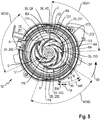
- a fixed diffuser is provided in the diffuser and / or pressure chamber with a base body, preferably elongated in the axial direction, in particular circular cylindrical, in which one or more guide vane sections in the direction of the impeller are axially delimited on the end wall facing the impeller chamber by their outer circumference protrude so that they each protrude into a liquid ejection region of the impeller arranged around the outer circumference of the impeller and each incline or incline away from it, in particular deviating from the radial direction in the impeller direction, towards the axial outer casing of the base body, in particular up to the axial outer casing of the base body, which is arranged radially further outward than the liquid ejection region, are in the rotational operation of the impeller of the liquid conveyed outward by this and also any air bubbles contained or entrained therein from the liquid ejection Defined flow guide paths in the region of the impeller in the direction, in particular up to the axial outer jacket of the
- These one or more axially projecting guide vane sections promote the removal of the liquid expelled or ejected by the rotatingly driven impeller and any contained or carried therein Air bubbles away from the liquid discharge area of the impeller and out of the impeller chamber into the diffuser and / or pressure chamber axially downstream of the suction direction, ie in the outflow direction.
- the one or more axially projecting guide vane sections therefore run outwards from the peripheral liquid ejection region of the impeller towards the axial outer jacket of the base body, in particular up to the axial outer jacket of the base body, expediently such that they swirl the circulation flow that otherwise occurs around the impeller during its rotational operation cause. In other words, they counteract the formation of a rotational flow, in which the liquid ejected by the impeller during its rotational operation revolves or circles around it one or more times.
- the course of the respective axially projecting guide vane section is preferably selected such that the liquid ejected on the periphery or outer circumference of the impeller during its rotational operation only has a circumferential angle of less than 360 °, in particular between 45 ° and 180 °, preferably between 50 ° and 135 °, viewed from its point of exit on the outer circumference of the impeller, to the axial outer jacket of the base body of the diffuser, which is arranged radially further outward.
- the one or more axially protruding guide vane sections thus limit the circular or peripheral path of the liquid ejected from the impeller with a radial component and a rotational component in the circumferential direction to a fraction of a 360 ° full circle.
- the impeller space around the outer circumference of the impeller is divided into several chambers or sectors by the one or more axially projecting guide vane sections, thereby reducing or avoiding the formation of a circulation flow in which the liquid ejected from the impeller has its periphery one or more times circulates.
- the diffuser construction according to the invention it is possible, in particular, to better prevent air from rotating in the rotating mode of the impeller when liquid is being conveyed Center of the impeller space, especially around the hub of the impeller.
- the one or more axially projecting guide vane sections ensure that air, which is present in a liquid-free cavity of the diffuser and / or pressure chamber, for example after the impeller has come to a standstill, can flow back into the center of the impeller space when the impeller starts up or starts.
- the one or more axially projecting guide vane sections facilitate their removal by the pumped liquid from the impeller chamber into the diffuser and / or pressure chamber, through it and then out of the pressure port.
- the respective axially projecting guide vane section leads an air bubble contained in the conveyed liquid, preferably in the manner of a ramp or other flow guide element, which is inclined relative to the radial direction in the running direction of the impeller, and outwards from the peripheral liquid discharge region of the impeller, in particular to the axial outer jacket of the main body of the diffuser to the axial outer casing of the base body, which is arranged radially further outward than the liquid discharge area of the impeller. Since the respective axially projecting guide vane section protrudes at least with its radially inner starting section into the peripheral liquid discharge area of the impeller, i.e.
- the liquid heating pump according to the invention is therefore characterized by an improved ventilation behavior with a shorter ventilation time both in the current liquid delivery mode and when the impeller is started or started.
- the liquid heat pump constructed according to the invention has far less or no occurrence during the rotating operation of the impeller Accumulation of air in the center of the impeller space around the hub or the shaft of the impeller, even if air is also sucked into the centrally arranged intake duct of the liquid heating pump when the liquid is being conveyed.
- the liquid ejected from the impeller with a radial and a circular speed component can only flow in a partial section, in particular sector section, of the preferably rotationally symmetrical, in particular approximately circular-cylindrical, impeller space which, viewed in the direction of rotation of the impeller, protrudes axially from a first one Guide vane section and a subsequent, second axially projecting guide vane section is limited.
- a liquid flow runs along it from the liquid ejection region of the impeller, which lies between the first and the second axially projecting guide vane section, from the outer circumference of the impeller in the direction, in particular to the axial outer casing of the base body outwards into the diffuser and / or pressure chamber.
- air bubbles contained in the liquid are also pressed into the diffuser and / or pressure chamber by the liquid being conveyed from the impeller space into the diffuser and / or pressure space by the liquid, via the respective vane section following the liquid exit point in the direction of rotation, in particular inclined relative to the radial direction in the direction of rotation.
- air bubbles sucked into the intake duct on the inlet side can flow through the liquid heating pump constructed according to the invention with a shorter throughput time and can be conveyed out of the outlet-side pressure nozzle than would be possible with a conventional liquid heating pump with a diffuser attached to it the end wall facing the impeller chamber has no guide vane sections projecting axially in the direction of the impeller.
- the course of the respective guide vane section projecting axially from the end wall of the base body facing the impeller space is selected such that it is radially effective for the liquid conveyed out of the impeller with a radial and a circular speed component.
- a portion of the kinetic energy given to the liquid by the rotating impeller can be converted into dynamic pressure.
- the liquid expelled from the rotating impeller retains part of its circular speed component and is not completely braked in the direction of rotation of the impeller.
- the respective axially projecting guide vane section deviates from a circular arc section extending in the circumferential direction of the end wall and which follows the direction of rotation of the impeller (and thus not in the form of a concentric circular ring section)
- the liquid can be deflected in the direction with a radial direction component the axial outer jacket of the base body and / or the outer boundary wall of the impeller space to be embossed.
- the kinetic energy induced by the rotatingly driven impeller into the liquid can already be partially converted into dynamic pressure.
- the liquid entering the diffuser and / or pressure chamber retains a sufficiently large part of the kinetic energy given to it by the impeller, so that the heating device assigned to the diffuser and / or pressure chamber can be acted upon with a sufficiently fast flowing liquid flow.
- This winds around the axial outer jacket of the preferably circular-cylindrical base body in a helical or helical manner through the preferably circular-cylindrical diffuser and / or pressure chamber to the outlet-side pressure port. It thus moves along this helical path of movement with an axial and a circular flow velocity component through the diffuser and / or pressure space.
- the heating device forms a partial section or the entire section of the outer boundary wall of the diffuser and / or pressure chamber - the electrical heating power provided by the heating device is largely uniformly and reliably viewed in the circumferential direction and in the axial direction by the im Pumped liquid can be removed without there is local overheating on the heating device. Less lime can also be deposited on the heating device.
- an outwardly opening arc section in particular a circular arc section, or preferably a spiral section or helical line section, in which the plane encompassed by the outer circumference of the end wall of the base body and / or a plane parallel to it extends.
- Such a course of the respective axially protruding guide vane section advantageously favors the detachment of the conveyed liquid from the peripheral outer circumference of the impeller into a flow path which (viewed in the direction of view from the impeller perpendicular to the end wall of the base body facing the impeller space) looks like a helix from the liquid discharge area of the impeller leads to the axial outer casing of the base body and then changes into a movement path which continues in the axial direction from the impeller space through the preferably circular-cylindrical diffuser and / or pressure space through the axial outer casing of the base body in a helical manner.
- the respective axially projecting guide vane section with its radially inner starting section is largely tangential from an inner circumferential point at the circle of the liquid discharge region of the impeller runs outwards and with its radially further outward end section opens largely tangentially at an outer circumferential point on the outer circumferential circle of the axial outer jacket of the basic outer circumference of the inner outer circumference of the main body.
- the respective axially protruding guide vane section runs in the plane of the front wall or a plane parallel to this in the form of a spiral section, the radius of curvature of which, from its radially inner beginning, to its radially further outer one End increases.
- the respective axially projecting guide vane section projects so far from the end wall of the base body of the diffuser toward the impeller that it faces the impeller space that at least along its initial portion facing the impeller liquid discharge region, in particular along its entire extent, the axial width of the diffuser Liquid discharge area of the impeller partially or completely covered from the outside.
- the axial outer jacket of the base body of the diffuser forms at least one, in particular axially extending, section of an inner boundary wall of the diffuser and / or pressure chamber.
- the, in particular circular-cylindrical, base body of the diffuser has an axial outer jacket, the diameter of which is selected to be at least equal to 80%, in particular between 80% and 90%, preferably approximately equal to 86%, of the outer diameter of the diffuser and / or pressure chamber is.
- the radial gap width of the diffuser and / or pressure chamber can be reduced so that the liquid flowing through it, along its preferably helical track, has an increased flow rate that is sufficient for the electrical heating power generated by the diffuser and / or or a heating device associated with the pressure chamber is provided in a reliable manner.
- the heating device has an axially extending section of the outer boundary wall of the diffuser and / or pressure space and the axial outer jacket (axial outer jacket) of the base body of the diffuser forms an axially extending section of the inner boundary wall of the diffuser and / or pressure chamber.
- the heating device can expediently be designed as a heating tube extending in the axial direction.
- this advantageous dimensioning of the diameter of the axial outer jacket of the diffuser in relation to the outer diameter of the diffuser and / or pressure chamber reduces the dead space volume in the pump housing for the liquid to be conveyed.
- annular passage cross-sectional area in the diffuser and / or pressure space there is an improved displacement effect for the liquid flowing through it. This results in a reduction in the total amount of liquid present in the liquid heating pump according to the invention.
- the expansion of the outer diameter of the base body of the diffuser to at least equal to 80%, in particular between 80% and 90%, preferably approximately equal to 86%, of the outer diameter of the diffuser and / or pressure chamber in comparison to a previous heating pump, such as corresponding to the WO 2008/125488 A2 with the same volume flow of liquid being conveyed, its flow velocity in the diffuser space, preferably already from the axial starting section of the diffuser and / or pressure space, increased to such an extent that the thermal heating power provided by the heating device can be largely completely transferred reliably to the liquid flowing past.
- the heating device can now be operated with a higher local thermal power density.
- a heating device with a shorter axial length than previously may be sufficient because of the now increased volume throughput.
- an embodiment of the liquid heating pump constructed in accordance with the invention is advantageous, in which the inside diameter of the diffuser and / or pressure chamber, or equivalent to this, the outside diameter of the, in particular circular-cylindrical, diffuser Base body, the axial outer jacket of which forms an axially extending section of the inner boundary wall of the diffuser and / or pressure chamber, between 5.5 cm and 6.5 cm, in particular approximately 6.2 cm, and the outer diameter of the diffuser and / or pressure chamber , the outer boundary wall of which is partially or completely in particular by the heating device, preferably a heating tube is formed, is chosen between 7 cm and 7.5 cm, in particular approximately equal to 7.3 cm.
- the outer diameter of the impeller is expediently chosen to be between 3.8 and 4.4 cm, in particular approximately 4.2 cm.
- Its diffuser which is designed according to the construction principle according to the invention, has three guide vane sections which protrude axially from one another by approximately 120 ° in the circumferential direction in the direction of the impeller space.
- the respective axially protruding guide vane section expediently projects into the impeller chamber with an axial extension of between 3 mm and 8 mm, in particular of approximately 5 mm, on the end wall of the base body.
- This axial extent corresponds approximately to the axial width of the peripheral liquid discharge region of the impeller, with the addition of the axial gap dimension between the end wall of the base body facing the impeller space and the suction-side end face of the impeller.
- this is formed by its suction-side, front cover disk.
- throughput times of at most 6 seconds, in particular between 3 seconds and 6 seconds, preferably of about 5 seconds, are advantageously made possible for air bubbles sucked in via the suction channel.
- the heating device in the diffuser and / or pressure chamber preferably on the part section formed by it or the overall section formed by it, of the outer boundary wall of the diffuser and / or pressure chamber, in particular when using the liquid heating pump designed according to the invention a household dishwasher - an electrical surface heating load between 30 W / cm 2 and 50 W / cm 2 ready.
- the passage cross-sectional area of the annular-gap-shaped diffuser and / or pressure chamber considered in cross section is expediently chosen between 8 cm 2 and 20 cm 2 , in particular around 12 cm 2 .
- the impeller especially with an outer diameter of approximately 4.2 cm, has a speed between 3800 and 4500 rpm, preferably with a speed of approximately 4200 rpm rotates, the volume flow rate of the liquid conveyed is so great that the heating power provided by the heating device can be transferred to the liquid flowing to it to such an extent that local overheating on the heating device leads to undesired lime deposits, thermal damage or even failure of the heating device could be largely avoided.
- the increase in the flow velocity of the liquid conveyed through the diffuser and / or pressure chamber preferably viewed in cross section, counteracts the build-up of lime layers on the heating device and accelerates the breakdown of any lime layers already formed on the heating device.
- the respective guide vane section projecting axially in the direction of the impeller is provided, in particular molded, on the end wall of the base body of the diffuser facing the impeller space or the suction side of the impeller such that it is in each case from its radially further inward beginning to viewed at its radially further outer end has an inclined position with respect to the radial direction of the impeller going through its beginning in the direction of rotation thereof.
- the liquid expelled from the impeller can transfer a large part of the kinetic energy impressed on it by the rotating impeller along its flow path in the impeller space, preferably in the form of a spiral section, from the peripheral liquid discharge region of the impeller to the axial outer jacket of the base body, which is located further outwards from it, into the diffuser and / or pressure space take.
- the one or more guide vane sections projecting axially in the direction of the impeller each have a direction of curvature in the direction of rotation of the impeller on the end wall of the base body of the diffuser facing the impeller space.
- the respective axially protruding guide vane section thus serves as a climbing aid or flow guide means for the liquid ejected radially further inward on the outer circumference of the impeller into the radially further outward lying diffuser and / or pressure chamber.
- a plurality, in particular three, axially projecting guide vane sections on the end wall of the base body facing the suction side of the impeller are each offset in the circumferential direction by approximately the same central angle such that between two axially projecting guide vane sections that are adjacent in the circumferential direction and viewed in the circumferential direction there is a liquid guide channel leading outwards to the axial outer jacket of the base body.
- three axially protruding guide vane sections these are expediently offset from one another by approximately 120 °, viewed in the circumferential direction.
- three liquid guide channels are available, starting from the liquid discharge area of the impeller up to the axial outer jacket of the base body.
- the base body of the diffuser can be kept structurally simple and manufactured, and yet the liquid ejected there can already be divided particularly uniformly around the diffuser and / or pressure space, which is in particular circular in cross section, around the outer circumference of the impeller.
- the radially outer edge zone of the end wall of the base body of the diffuser facing the suction side of the impeller merges smoothly into the axial longitudinal extent of the axial outer shell of the base body in the form of a rounding.
- the hydraulic efficiency of the liquid heating pump designed according to the invention is further improved, since undesirable losses in kinetic Energy that has been given to the liquid by the rotating impeller can be avoided in a further improved manner when entering the diffuser and / or pressure chamber.
- the respective axially protruding guide vane section can be arranged and designed on the end wall of the base body facing the impeller space in such a way that, at least with its initial section, in particular along its entire extent, the outside circumferential liquid ejection region of the impeller with a remaining one essentially over its axial width
- Radial gap covered, which (viewed in the direction of flow) in the area of its beginning is chosen in particular between 0.5 mm and 2 mm. This radial gap provides sufficient play for the unimpeded rotation of the impeller.
- the remaining radial gap is chosen so small that the formation of a circular flow around the impeller is largely avoided. Leakage currents circulating around the impeller are thereby largely avoided, so that the volumetric efficiency of the liquid heating pump is improved.
- the one or more blades of the impeller each have an oblique position with respect to the radial direction of the impeller against the direction of rotation of the impeller, in particular a direction of curvature against the direction of rotation of the impeller.
- the radially further inward beginning of the respective guide vane section of the base body projecting axially on the face end preferably has a contour that is different from the contour of the outlet end End of the respective blade of the impeller is different.
- one or more, in particular three, vane segments protruding radially from the liquid flow in the diffuser and / or pressure space are additionally provided on the axial outer jacket of the base body of the diffuser.
- these can be provided independently, in particular unconnected to the one or more axially protruding guide vane sections and thus each separated by a gap.
- these radially projecting guide vane sections each protrude radially into the diffuser and / or pressure space between 2 and 3 mm from the axial outer jacket of the base body.
- the liquid flow passes through the diffuser and / or pressure chamber in such a way that it winds around the diffuser base body or the inner boundary wall of the diffuser and / or pressure chamber in a helical or helical manner with a pitch or pitch in the axial direction.
- the heating device forms, for example, a partial section or the entire section of the outer boundary wall of the diffuser and / or pressure chamber. This is because, in the circumferential direction as well as in the axial longitudinal direction of the heating device, sufficient, in particular largely homogeneous, removal of the thermal heating power provided by the heating device and transfer to the conveyed liquid can be ensured.
- the helical section causes or helix section of the respective axially outer jacket side radially protruding guide vane section viewed upstream in an advantageous manner, in particular a barrier that makes it difficult or impossible for an air bubble that may be present in the diffuser and / or pressure chamber to flow back into the impeller chamber against the axial pump outflow direction.
- radially protruding guide vane sections are arranged offset in relation to one another in the form of spiral sections around the axial outer jacket of the, in particular circular cylindrical, base body. They are preferably positioned separated from one another by approximately the same central angle range.
- the radially protruding vane sections which are largely evenly distributed in the circumferential direction of the axial outer jacket, act largely uniformly on the liquid conveyed by the diffuser and / or pressure chamber, which is preferably annular in cross section.
- they also serve in particular to avoid a direct short-circuit flow path for the conveyed liquid on its way from the entrance of the diffuser and / or pressure chamber to the pressure port. In this way, the liquid flowing through the diffuser and / or pressure space along a helical path can be optimally heated by the heating device provided there.
- the respective radially projecting guide vane section on the axially outer casing side on the axial outer jacket of the base body of the diffuser extends at least in an outer peripheral region of the base body, which lies between the radially further outward end of a first axially projecting guide vane section and the radially further inward start of a second axially projecting guide vane section, viewed in the direction of rotation of the impeller.
- the respective axially outer jacket-side radially projecting guide vane section provides an axial lock in the return direction to the impeller chamber for an air bubble, which is located downstream of this radially projecting guide vane section, possibly in the diffuser and / or pressure chamber or in the pressure chamber or pressure nozzle downstream of it. This is particularly advantageous for perfect venting of the liquid heating pump when pumping is started after a standstill phase.
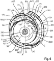
- the respective guide vane section projecting axially from the end wall of the base body into the impeller space preferably extending in an arc-like manner, preferably in a spiral section
- a connecting section in particular molded onto it
- the connecting section with it in the direction of rotation of the impeller subsequent, axially outer side associated, radially projecting, preferably helically extending, guide vane section is connected continuously, in particular essentially continuously, to form a combined guide vane.
- This combined guide vane enables the fluid to have an even better flow path from the peripheral fluid ejection area of the impeller in the impeller chamber into the diffuser and / or pressure chamber and through it.
- the connecting section expediently runs along an outer peripheral section of the end wall of the base body facing the impeller space.
- the connecting section preferably has an axially projecting, in particular circular section, web section and additionally a radially projecting, in particular helical, web section on its axial end face.
- the radially projecting web section acts in the axial direction as a barrier or obstacle which, in the axial direction, hinders or avoids an air bubble flowing back from the diffuser and / or pressure chamber back into the impeller chamber and thus ultimately into the center of the impeller chamber if the Liquid heat pump works in pump mode.
- the axially projecting web section serves as an extension of the radially outer end section of the axially projecting guide vane section of the combined guide vane and preferably enables a continuous transition into the associated guide vane section projecting radially axially on the outer shell side.
- the axially projecting web section has an axial extent or extension, which decreases, in particular continuously, from its start connected to the axially projecting guide vane section to its end connected to the guide vane section projecting radially on the outer shell side.
- the axially projecting web section in the impeller chamber acts as a barrier or obstacle to the radial ejection direction of the impeller, which makes it more difficult or impossible for an air bubble to flow back from the diffuser and / or pressure chamber in the radial direction back to the center of the impeller chamber if the liquid heating pump works in pump mode.
- the connecting section connects the front, axially projecting guide vane section to the associated axially outer jacket-side, radially projecting guide vane section, in particular in one piece and / or in the same material as a continuous guide vane.
- the diffuser as a whole can be easily manufactured.
- the respective guide vane section projecting axially from the end wall of the base body into the impeller space expediently runs in an arc shape, preferably in the form of a circular arc section or in a spiral section (viewed in a normal plane to which the axis of rotation of the impeller is perpendicular), and then extends radially outward in an outer edge zone of the end wall of the base body by means of the connection section which is preferably molded onto it, in the following, viewed in the direction of rotation of the impeller, axially outer, radially projecting, preferably helically extending, guide vane section, which is assigned to it in the direction of rotation of the impeller.
- the axially projecting web section of the connecting section extends the axially projecting guide vane section, in particular in the form of a circular arc section.
- the radially projecting web section of the connecting section extends the axially outer jacket-side, radially projecting guide vane section preferably in accordance with its shape, in particular spiral shape.
- the liquid when looking at the one or more axial guide vane sections equipped end wall of the base body, is detached from the outer circumference of the rotating impeller and is conveyed along a spiral section-like route to the diffuser and / or pressure space arranged radially further outward and then spatially viewed in the axial direction it moves helically around the base body through the diffuser and / or pressure space .
- this further improves the hydraulic efficiency of the liquid heating pump designed according to the invention and its venting behavior.
- the respective radially projecting guide vane section when looking at the end wall of the base body facing the impeller space, runs on the axial outer jacket of the base body of the diffuser and its upstream-side extension formed by the radially projecting web portion of the connecting section in an outer peripheral region of the base body in the gap between the radially outer side End of a first axially projecting guide vane section and the radially outer end of an adjacent, axially projecting guide vane section viewed in the direction of rotation of the impeller.
- This ensures an effective non-return valve for air bubbles so that they cannot flow back from the diffuser and / or pressure chamber back to the center of the impeller chamber when the liquid heating pump is operating in pump mode or pump operation is restarted after a standstill phase.
- an axially projecting guide vane section and its connecting section to the associated guide vane section projecting radially axially on the outer casing side are arranged in the upper region of the end wall of the base body facing the shop wheel space such that they are one above the Base body in the diffuser and / or pressure chamber existing air bubble in the way to flow back towards the center of the impeller chamber in the rotating operation of the impeller.
- the respective radially projecting guide vane section when looking at the end wall of the base body facing the suction side of the impeller, runs on the axial outer jacket of the base body of the diffuser and its upstream extension through the radially projecting one Web section of the connecting section in an outer peripheral region of the base body in the gap between the radially outer end of a first axially projecting guide vane section and the radially outer end of a second axially projecting guide vane section viewed in the direction of rotation of the impeller.
- the radially projecting web section of the connecting section thereby causes an axial blockage for an air bubble which is located downstream of the connecting section in the diffuser and / or pressure chamber, so that the air bubble is prevented from flowing back into the impeller chamber during the rotational operation of the impeller. This results in an excellent self-venting behavior of the liquid heating pump according to the invention.
- the respective guide vane section axially projecting on the end wall of the base body facing the impeller space or the suction side of the impeller ends on the outer circumference of the base body at the circumferential position at which the guide vane section preceding in the direction of rotation of the impeller and radially projecting axially on the outer jacket side ends downstream viewed on the axial outer jacket of the base body ends at an axial distance from the end wall of the base body of the diffuser facing the impeller space or the suction side of the impeller.
- the diffuser can be manufactured in a simple manner by means of two tool parts or molded parts that can be moved towards and away from one another in the axial direction in the plastic injection molding process, and that the radially projecting and axially projecting guide vane sections (as well as their connecting sections, if any) are properly removed from the mold Basic body of the diffuser is made possible.
- the base body of the diffuser is fixed or attached to the housing of the centrally arranged intake duct. This avoids redesigning the pump housing so that it can be used for a large number of different types of liquid heating pumps. It can be particularly simple if a tubular section is provided, in particular molded, on the inside of the base body of the diffuser, which tube section forms an axial partial section, in particular end section, of the centrally arranged intake duct. As a result, the diffuser can be installed particularly easily in the flow path of the liquid heating pump according to the invention.
- an embodiment of the invention constructed liquid heating pump is favorable, in which the inner diameter of the diffuser and / or pressure chamber or the outer diameter of the, in particular circular cylindrical, diffuser base body, the axial outer shell of which forms an axially extending partial section or the entire section of the inner boundary wall of the diffuser and / or pressure chamber, between 5.5 cm and 6.5 cm, in particular approximately 6.2 cm, and the outer diameter of the diffuser and / or pressure chamber, the outer boundary wall of which is partly or entirely formed by the heating device, preferably a heating tube, between 7 cm and 7.5 cm, in particular is approximately equal to 7.3 cm.
- the outer diameter of the impeller is expediently chosen to be between 3.8 and 4.4 cm, in particular approximately 4.2 cm.
- the base body of the diffuser of this tested liquid heating pump is designed as an elongated circular cylinder. It preferably has an axial length between 2 cm and 4 cm. It has three combined guide vanes according to the explanations above. When viewed in the circumferential direction, they are expediently offset from one another by approximately 120 °.
- the respective axially protruding guide vane section viewed in the circumferential direction, preferably extends over a central angle range between 50 ° and 90 °, its connecting section in the circumferential direction preferably viewed over a central angle range between 30 ° and 60 °, and the radially projecting guide vane section assigned to it axially on the outer jacket side, preferably over a central angle range between 50 ° and 90 °.
- the diffuser is expediently oriented in this way in its fixed installation position aligned that one of the three axially protruding guide vane sections viewed in the polar coordinate system in the angular range between 10 ° and 90 °, its connecting section in the angular range between 90 ° and 135 °, and the radially protruding guide vane section assigned to it on the axially outer jacket side in the angular range between 135 ° and 205 ° runs.
- This lead time is related to the time to be observed by the individual liquid-carrying partial rinse cycles of the rinse cycle of a dishwashing program to be carried out cheaply in a household dishwasher.
- the respective axially projecting guide vane section expediently protrudes from the end wall of the base body into the impeller chamber with an axial extension between 3 mm and 8 mm, in particular of approximately 5 mm.
- this corresponds approximately to their axial distance, with the addition of the axial gap between the end wall of the base body facing the impeller space and the suction-side end face of the impeller.
- the invention also relates to a water-carrying household appliance, in particular a domestic dishwasher or a household washing machine, with a liquid heating pump designed according to the invention.
- liquid heating pump which is installed in a domestic dishwasher, is explained below.
- This liquid heating pump can optionally also be provided in other liquid-carrying household appliances, such as, for example, in a washing machine as a component of its washing unit or liquid circulation circuit.
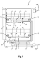
- FIG. 1 shows a schematic representation of a household dishwashing machine viewed from the side 1.
- This has a washing container 2 for holding items to be cleaned and then dried, such as dishes, pots, cutlery, glasses, cooking utensils and the like.
- the washing container 2 preferably has an essentially rectangular plan (viewed from above) with a front side V facing the user in the operating position.
- the door 3 is in the Figure 1 Shown in the closed position and pivotable, for example, about a lower horizontal axis 3a.
- the loading opening can also be provided at another location on the washing compartment, such as in the top thereof, and can be opened and closed with a closure element, such as a flap.
- washing baskets 4, 5 are provided for receiving or holding items to be washed.
- washing baskets 4, 5 are provided in the interior of the washing compartment 2.
- the number of washing baskets can vary depending on the extent and type of household dishwasher 1.
- a cutlery drawer can also be provided.
- These crockery baskets 4, 5 are provided with fresh water FW and / or with circulating water via one or more spray devices 6, 7, 8, which can be mixed with detergent, rinse aid and / or other auxiliary substances depending on the partial rinse cycle of the dishwashing cycle of a dishwashing program. ie with so-called wash liquor or wash liquor, and thus, in general terms, can be charged with wash liquid FL, which mainly contains water.
- Rotatable spray arms are preferably provided in the interior of the washing compartment 2 as one or more spray devices.
- two rotatable spray arms 6, 7 are accommodated in the washing compartment 2, which act on the items to be washed in the crockery baskets 4, 5 in particular with an upwardly directed spray component.
- the lower spray arm 6 is arranged below the lower crockery basket 4.
- the upper spray arm 7 is arranged below the upper crockery basket 5.
- other types of spray devices can also be provided.
- one or more individual spray nozzles can also be accommodated in a fixed manner in the washing compartment 2.
- a spray device 8 is arranged below the upper crockery basket 5 and assigned to it. It comprises one or more individual nozzles that also convey the liquid FL with an upward-pointing component to the wash ware in the upper crockery basket 5.
- a downward spray component can also be applied.
- liquid spray jets can also be directed downward from the upper spray arm 7 onto the items to be washed in the lower dish rack 4.
- Other spray devices are also possible as an alternative or in addition.
- a so-called roof shower can be provided on the ceiling wall of the washing compartment 2, which is shown here in the Figure 1 has been omitted for the sake of simplicity.
- washing baskets 4, 5 can be moved forward, for example on rollers 10, in order to achieve an access position for the user in which the washing baskets 4, 5 can be conveniently loaded and unloaded.
- Lateral rails in the washing compartment 2 are provided as tracks for the rollers 10. If necessary, pulling and pushing handles can be provided on the respective front edge levels of the washing baskets 4, 5 to simplify the pushing in and out of the washing baskets 4, 5.
- the treatment liquid FL containing predominantly water runs downwards after being distributed in the wash tank 2 while spraying onto the wash ware a collection area or pump sump 11, which is preferably recessed in the bottom of the rinsing container 2.
- the liquid passes through a sieving unit, which in the Figure 1 is also indicated by dashed lines. From this collection area, the liquid is guided in the spray mode or circulating mode of the spray devices to a liquid heating pump 12 which is fluidly connected to the collection area 11 or is sucked in by the latter.
- the liquid heating pump 12 comprises a circulation pump and, in combination, additionally a heating device.
- the circulation pump of the liquid heating pump 12 the liquid is pumped to a distributor unit 14, in particular a water switch, which is in fluid communication with it, and from there it is directed to the spray devices 6, 7, 8. Possibly. the distribution unit can also be omitted.
- a distributor unit 14 in particular a water switch, which is in fluid communication with it, and from there it is directed to the spray devices 6, 7, 8. Possibly. the distribution unit can also be omitted.
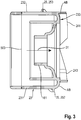
- FIG. 2 shows a schematic longitudinal sectional view of a first advantageous embodiment of a liquid heating pump 12 designed according to the invention. It comprises two main assemblies: a first housing part 28 with one accommodated therein Drive unit 18, in particular an electric motor housed therein, and a second housing part 29 with a hydraulic unit 19 housed therein.
- the electric motor 18 is mounted such that its drive shaft 20 is oriented essentially in the axial direction AR.
- the axial direction AR can preferably run essentially horizontally, as here in the exemplary embodiment, if the liquid heating pump 12 is installed below the bottom of the washing compartment 2 in the base assembly of the domestic dishwasher 1.
- the first housing part 28 is essentially hollow-cylindrical.
- the drive shaft 20 protrudes from the end wall of the first housing part 28 facing the hydraulic unit 19 with one end section.
- an impeller 17 is fixedly attached on the end face. This is essentially circular in cross-section, ie in a sectional plane to which the axis of rotation 191 of the impeller extends perpendicularly.
- the second housing part 29 is also essentially hollow-cylindrical.
- the first housing unit 28 and the second housing unit 29 are joined together in the axial direction via, preferably releasable, coupling means or fastening means 30 to form a closed, compact pump housing.
- Both the first housing part 28 with the drive unit 18 accommodated therein and the second housing part 29 with the hydraulic unit 19 housed therein are each preferably essentially rotationally symmetrical with respect to the axis of rotation 191 of the drive shaft 20 or its imaginary extension as the central axis of the liquid heating pump 12.
- the hydraulic unit 19 comprises a centrally arranged suction channel 16 for sucking the liquid FL in an axial suction direction 31 and for feeding the sucked liquid FL into an axially downstream impeller space 40.
- the liquid FL is in the Figure 2 symbolized by puncturing.
- the central axis 192 of the intake duct 16 is aligned with the axis of rotation or central axis 191 of the drive shaft 20.
- the intake duct 16 is preferably formed by one or more circular-cylindrical tube sections, which are each arranged concentrically to the central axis 192 of the liquid heating pump 12.
- the impeller chamber 40 is viewed in the suction direction 31 by a Limited rear wall, which is formed by one or more wall parts on the end face of the first housing part 28, on which the drive shaft 191 with the impeller 17 attached to it protrudes into the impeller chamber 40 against the suction direction 31. Furthermore, the impeller chamber 40, viewed in the suction direction 31, is delimited by a front wall, which is formed by one or more wall parts on the end wall of the second housing part 29, which faces the first housing part 28.
- the intake duct 6 opens out with its central outlet opening 401, viewed in cross section, that is, its central axis 192 is aligned with the axis of rotation 191 of the drive shaft 20.
- the axial width of the impeller chamber 40 is selected such that an axial gap ASP and a radial gap RS remain between the end wall of the tubular, in particular circular-cylindrical suction channel 16 facing the impeller 17 and the suction-side end wall of the impeller 17 in order to ensure the free rotation of the impeller 17.
- the axial gap ASP expediently has an axial width between 0.5 mm and 1.5 mm and the radial gap RS has an axial width between 0.5 mm and 1.5 mm.
- the impeller is preferably designed as an impeller. Viewed in the axial suction direction 31, it has a front cover disk 171 which faces the intake duct 16 and a rear cover disk 172 which is axially spaced and faces the first housing part 28.
- the blades 174 of the impeller 17 extend between the two cover disks 171, 172.
- Both the front cover disk 171 and the rear cover disk 172 are each viewed from the intake duct 16 in the opposite direction to the axial intake direction 31, ie curved backwards. In particular, they are each concave.
- a centrally arranged inlet opening 402 is provided in the front cover disk 171, which is essentially aligned with the outlet opening 401 of the outlet channel 16.
- the rear cover plate 172 is closed.
- the impeller 17 is attached to the drive shaft 20 in such a way that its rear cover disk 172 is arranged in a receiving recess in the rear wall of the impeller chamber 40, which is recessed in the axial direction AR and has a predetermined axial gap to the rear wall and is therefore freely rotatable, ie not abutting.
- the curvature of the rear cover disk 172 is largely continued or supplemented by the wall section of the rear wall of the impeller chamber that surrounds it radially further outward, largely without axial displacement.
- the impeller blades 174 each bridge the axial gap distance between the two axially spaced, opposite cover disks 171, 172 and are attached, in particular fastened, to their mutually facing inner walls. There is a liquid passage between each two adjacent impeller blades 174 in the circumferential direction.
- the blades 174 of the impeller 17 are each curved counter to the direction of rotation 60 of the impeller 17. They each run in the form of an outwardly opening circular arc section or spiral section, the radially inner end of which begins approximately at the circumferential circle of the inlet opening 402 of the front cover disk 171 and the radially outer end of which ends approximately at the outer circumference or outer diameter of the front and rear cover disks 171, 172.
- the respective blade of the impeller is preferably set in relation to the radial direction (viewed in a normal plane to which the axis of rotation 191 is perpendicular). If the impeller 17 is driven in rotation by means of the drive unit 18 via the drive shaft 20, the liquid FL present in the impeller chamber 40 is moved outward from the center of the impeller 17 with a radial and a circular or azimuthal speed component into the radially outer region of the impeller chamber 40 pressed. As a result, there is a higher pressure in the impeller chamber 40 on the radially outer circumference of the impeller than in the center thereof. In this way, the impeller 40 draws liquid through the suction channel 16 out of the pump sump or collection area 11.
- the backward curvature of the front cover disk 171 and of the rear cover disk 172 and of the rear wall supports the fact that the liquid conveyed by the impeller runs through a curved path and is deflected in the opposite direction to the suction direction 31. This approximately 180 ° deflection is in the Figure 2 illustrated with the directional arrow 32.
- the impeller can optionally - as here in the embodiment of Figure 2 - be expedient if the rear wall surface of the impeller chamber and / or the initial section of the diffuser and / or pressure chamber, which directly follows the impeller chamber when viewed in the flow direction, also contributes to the liquid being conveyed from the axial suction direction 31 by about 180 ° in the opposite direction , ie to redirect in the axial outflow direction.
- the impeller has a liquid ejection area around its outer peripheral edge, from which the liquid is thrown outwards from the passages between its blades during pumping or rotating operation (ie with a rotating impeller).
- This peripheral liquid discharge area is in the Figures 1 - 8 each designated 173. With the impeller 17 the Figures 1 - 8 lies the peripheral fluid ejection area between the front and rear covers 171, 172.
- the fluid FL conveyed in this way by the impeller 17 then flows into a diffuser and / or pressure space 50, which is axially arranged downstream in relation to the suction direction 31.
- This is arranged at least along a partial section of the suction duct 16 around the outside thereof. It surrounds the intake duct 16 essentially concentrically or coaxially.
- the diffuser and / or pressure chamber 50 Viewed in cross section, ie in a sectional plane transverse to the axial longitudinal extent of the liquid heating pump 12, to which the axis of rotation 191 runs essentially perpendicularly, the diffuser and / or pressure chamber 50 is essentially circular.
- a diffuser or a flow conditioning device 23 is provided in a fixed manner, which partially converts the kinetic energy induced by the rotational movement of the impeller 17 into the liquid flow into static pressure. It has an elongated base body 231, which forms an axially extending section of the inner boundary wall or the entire inner boundary wall of the diffuser and / or pressure chamber 50. It can be expedient that - as here in the exemplary embodiment of Figure 2 - On the inside of the base body 231 of the diffuser 23, a tube section is provided, in particular integrally formed, which forms an axial section, preferably an end section facing the impeller 17, of the centrally arranged intake duct 16.
- the base body 231 of the diffuser 23 can be supported on the housing of the centrally arranged intake duct 16 or to be attached there.
- the base body 231 is additionally fixed or attached to the housing part 29 via an axially extending, tubular support section SAB.
- the base body 231 preferably has an elongated, essentially circular-cylindrical tube, the end wall of which facing the impeller 17 is designed as a wall around the outlet opening 401 of the suction channel 16 and, viewed in the axial suction direction 31, forms the front boundary wall of the impeller chamber 30.
- This end wall has an annular receiving trough AM1 for the front cover disk 171 of the impeller 17 which is arranged around the outlet opening of the intake duct 16.
- the inner contour of this receiving trough largely corresponds to the suction-side outer contour of the front cover disk 171.
- the radially outer edge zone of the end wall 233 of the base body 231 facing the suction side of the impeller 17 expediently merges into the axial longitudinal extent of the axial outer jacket 232 of the circular-cylindrical base body 231 in the form of a rounding AB.
- This rounding AB is also viewed from the intake duct 16 in the axial intake direction 31 backwards, in particular concave, curved.
- This frontal rounding AB at the transition from the end wall 233 of the base body 231 into the axial outer jacket 232, in particular into the circular cylinder jacket surface, of the base body 231 largely prevents undesirable influencing of the direction, eddy losses, or braking of the liquid FL ejected by the impeller 17.
- this rounding AB between the radially outer edge zone of the end wall 233 of the base body 231 and the circular-cylindrical axial outer jacket 232 also favors the reversal path of the liquid flow from the axial suction direction 31 in the 180 ° counter direction.
- a trough or groove can optionally be provided on the radially outer edge zone of the end wall 233 of the base body 231 facing the suction side of the impeller 17 as a transition zone between the end wall 233 and the axial outer casing 232.
- a heating device 26 is assigned to the diffuser and / or pressure chamber 50 and serves to heat the liquid FL conveyed by the impeller 17.
- the heating device preferably forms a preferably axially extending partial section or the preferably axially extending total section of the outer boundary wall of the diffuser and / or pressure chamber 50.
- the heating device 26 is advantageously a preferably circular-cylindrical heating tube HZ extending in the axial direction AR.
- This heating tube HZ surrounds the circular-cylindrical base body 231 from the outside essentially concentrically or coaxially along an axial partial length or as here in the exemplary embodiment of FIG Figure 2 essentially along the total axial length of the base body 231 with a predetermined radial gap distance 501 such that the diffuser and / or pressure space 50 between the axial outer jacket 232 of the circular-cylindrical base body 231 and the axial inner jacket 261 of the circular-cylindrical heating tube HZ is viewed in cross section, ie in a normal plane considered, to which the axis of rotation is perpendicular, is formed in an annular gap.
- the radial gap distance 501 of the diffuser and / or pressure chamber 50 between the axial outer casing 232 of the preferably circular-cylindrical base body 231 and the smooth axial inner casing 261 is, on the other hand, radial Further preferably arranged, preferably circular cylindrical heating tube HZ between 3 mm and 8 mm, in particular around 5.5 mm. This is a significant reduction, in particular approximately a halving of the radial gap dimension between the axial outer jacket 232 of the base body 231 and the liquid-flowed axial inner jacket surface 261 of the heating tube HZ compared to liquid heating pumps previously used in household dishwashers.
- the base body of the diffuser in particular a circular cylinder, is expediently expanded or enlarged such that the outer diameter 503 of its axial outer jacket 232 is at least equal to 80%, in particular between 80% and 90%, preferably approximately equal to 86% of the outer diameter 505 of the diffuser - And / or pressure chamber 50 or the outer diameter 505 of the outer boundary wall 261 of the diffuser and / or pressure chamber 50.
- This can further reduce the so-called carryover of dirty water, which can occur when changing the rinsing bath, i.e. if the amount of rinsing bath used for a water-carrying partial rinse in a dishwashing program is partially or completely pumped out of the dishwashing container of the dishwasher using the drain pump and for the next water-carrying partial rinse in this dishwashing program Fresh water for a new rinsing bath is let into the rinsing tank.
- the circulation pump of the liquid heating pump is usually switched off during the emptying process of the preceding, completed partial rinse, the dirty rinsing liquid used remains from this preceding water-carrying partial rinse and only when the liquid heating pump is restarted in the subsequent partial rinse does this amount of already used rinse water from the liquid heating pump become pumped out and introduced into the rinsing container in the running partial rinse cycle via the one or more spray devices. Because of the reduced dead space volume in the liquid heating pump according to the invention, less water overall can also be used per rinsing bath. By reducing the annular passage cross section of the diffuser and / or pressure chamber, the flow rate of the liquid flowing through it is also increased.
- the inner wall surface 261 of the preferably circular-cylindrical heating tube HZ therefore tends to form less limescale deposits, which deteriorate the heat transfer from the heating device 26 to the liquid FL, here from the inner wall surface 261 of the heating tube HZ to the liquid flowing through it, and therefore less so Formation of so-called hot spots, ie local overheating points, which can lead to thermal and / or electrical damage to the heating device.
- the diameter 505 of the impeller chamber 40 is also enlarged compared to the outer diameter 504 of the impeller 17.
- it is chosen to be approximately equal to the diameter of the outer boundary wall of the diffuser and / or pressure chamber.
- an initial section of the heating device 26 can already be accommodated in the impeller chamber 40, which then extends further into the downstream diffuser and / or pressure chamber 50.
- an initial section of the heating device 26 forms part or all of the outer boundary wall of the impeller chamber.
- the axial length of a liquid heat pump which is advantageously designed in this way can be shortened compared to the previous liquid heat pumps, so that for it (compared to a construction in which the initial section of the heating device only begins in the diffuser and / or pressure space) less installation space in the base assembly of the dishwasher 1 from Figure 1 is needed.
- the heating device is expediently provided by a heating tube HZ, which forms the outer boundary wall 261 of the diffuser and / or pressure space 50 along a partial length or the entire length of its axial extent.
- the heating tube HZ can in particular e.g. comprise a circular cylindrical metal tube, the smooth inner lateral surface or inner wall surface 261 of which is flowed by the pumped liquid.
- the heating conductor tracks can expediently be covered on the outside by an additional covering layer, in particular an electrical insulation layer.
- the electrical insulation layer, the heating conductor tracks, and / or the cover layer can in particular be made with a thick-film technology or with a physical vapor deposition process, such as e.g. PVD ("physical vapor depositon") method.
- PVD physical vapor depositon
- the heating device 26 preferably sets a washing program to be carried out for heating the washing liquid to a desired temperature in the respective partial rinse cycle, such as, for example, in the cleaning cycle or rinse cycle an electrical surface heating load between 30 W / cm 2 and 50 W / cm 2 ready.
- the passage cross-sectional area QF of the diffuser and / or pressure chamber 50 is advantageously chosen between 8 cm 2 and 20 cm 2 , in particular by approximately 12 cm 2, for thermal removal thereof by means of the liquid FL pumped.
- This dimensioning is particularly advantageous if the impeller - especially with an outer diameter of approximately 4.2 cm - expediently rotates between 3800 and 4800 rpm, in particular around 4200 rpm, in pumping operation.
- the outer diameter of the impeller is chosen in particular between 3.8 and 4.5 cm, preferably around 4.2 cm.
- the circular-cylindrical diffuser base body of this successfully tested liquid heating pump expediently has an outer diameter of approximately 6.2 cm, and the heating tube has an inner diameter of approximately 7.3 cm.
- the liquid heating pump 12 has a centrally arranged suction channel 16 for sucking the liquid FL in an axial suction direction 31 and for feeding the sucked liquid into an axially downstream impeller chamber 40.
- An impeller 17 is provided such that it can be driven in rotation in the impeller chamber 40 in order to convey the liquid into a diffuser and / or pressure chamber 50, which is axially arranged counter to the suction direction 31.
- This diffuser and / or pressure space is preferably arranged coaxially around the outside of an axial section or the entire axial section of the intake duct 16.
- a fixed diffuser 23 is assigned to the diffuser and / or pressure chamber 50.
- This has a, in particular circular cylindrical, base body 231, the end wall 233 of which faces the impeller 17 has a suction-side, i.e. front boundary wall of the impeller chamber 40, and the axial outer casing 232 of which forms a, in particular axially extending, partial section or the, in particular axially extending, entire section of the inner boundary wall of the diffuser and / or pressure chamber 50.
- the heating device 26 assigned to the diffuser and / or pressure chamber 50 for heating the conveyed liquid FL expediently forms at least one, in particular axially extending, partial section or the, in particular axially extending, entire section of the outer boundary wall 261 of the diffuser and / or pressure chamber 50.
- the diffuser and / or pressure chamber 50 which is arranged concentrically around the intake duct 16, is viewed against the intake direction 31, ie in the axial outflow direction, followed by a housing outlet 271, preferably with an axial extension with a helical or spiral section, with an associated outlet side, laterally, in particular approximately tangentially, tubular discharge nozzle 272 for ejecting the liquid FL after.
- a housing outlet 271 preferably with an axial extension with a helical or spiral section, with an associated outlet side, laterally, in particular approximately tangentially, tubular discharge nozzle 272 for ejecting the liquid FL after.
- the upward outflow direction of the liquid conveyed is indicated by a directional arrow 34.
- the central axis ZA of the pressure port 272 is inclined with respect to the radial direction RR opposite to the axial suction direction 31, ie in the outflow direction, preferably by an acute angle SWI, in particular between 5 ° and 20 °, preferably around 10 °.
- SWI acute angle
- the liquid heating pump 12 is expediently installed in a base support or a base assembly below the base of the washing container 2 in such a way that the pressure connection 272 from the second housing part 29 upwards in the direction of the base of the Rinsing container 2 protrudes.
- the liquid heating pump 12 is thus installed in the dishwasher 1 with an axis of rotation of its drive shaft running essentially in the horizontal or in the axial direction and thus lying in the base assembly below the base of the washing compartment 2.
- the outlet 271 with the pressure port 272 is preferably designed as an outwardly opening spiral section which is molded onto the second housing part 29 on the end wall facing away from the first housing part 28 and with respect to the cross-sectional plane to which the axis of rotation 191 runs perpendicularly, runs obliquely against the axial suction direction 31 or opposite the direction of gravity by an acute angle, the liquid flow, which is in the diffuser and / or pressure chamber 50, preferably in the form of a helix or helix which migrates in the axial outflow direction counter to the suction direction 31 Pressure port too moved, are conveyed out of this while continuing this flow movement out of the pressure port 272.
- the hydraulic-mechanical efficiency captures in particular pressure losses and friction losses in the components of the liquid heating pump. However, their volumetric efficiency is determined in particular by any leakage losses that may occur.
- the impeller has spatially curved blades, that is to say so-called 3D blades, instead of simply curved blades.
- 3D blades instead of simply curved blades.
- a so-called semi-axial - semi-radial impeller is used.
- a so-called radial impeller can also be accommodated in the impeller space 40.
- a so-called closed impeller is provided, in which the impeller blades are connected to a disk on both sides. This increases the hydraulic efficiency and stabilizes the impeller.
- the first housing part 28 with the preferably electrical drive unit 18 contained therein is omitted.
- the direction of view goes towards the end wall of the second housing part 29 facing the first housing part 28 with the hydraulic unit 19 contained therein
- Figure 4 show the Figure 5 now the front wall facing the first housing part 28 of the opened second housing part 29 of the liquid heating pump 12 from Figure 2 when viewed in the axial outflow direction, the rear cover disk 172 of the impeller 17 of the hydraulic unit 19, viewed in the suction direction 31, also being omitted.
- the Figure 6 finally schematically illustrates a perspective view of the detail of the liquid heating pump 12 of FIG Figure 4 their diffuser 23 together with the impeller 17 (viewed in the suction direction 31) after its end wall 233.
- the three axially protruding guide vane sections 241, 242, 243 are arranged on the end wall of the fixed base body 231 facing the impeller chamber in the circumferential direction so as to be fixedly offset from one another in the circumferential direction by approximately the same central angle of approximately 120 ° such that between two axially protruding guide vane sections that are adjacent in the circumferential direction such as 241, 242 from the peripheral liquid ejection region 173 of the impeller 17, there is a liquid guiding channel such as RK12, which leads in the end wall 233 of the base body 231 facing the impeller space 40 to the outside to the axial outer jacket 232 of the base body 231.
- liquid guide channels RK12, RK23, RK31 are available, starting from the outer circumferential or peripheral liquid ejection region 173 of the impeller 17 up to the axial outer casing 232 of the base body 231.
- the liquid guide channel RK12, between the second axially projecting guide vane section 242 and the third axially projecting guide vane section 243 which follows in the circumferential direction the liquid guide channel RK23 and between the third axially projecting guide vane section 243 and the circumferentially following first axially projecting guide vane section 241 the liquid guide channel RK31 is provided.
- the respective axially projecting guide vane section 241, 242, 243 extends approximately from the circumferential circle, which is predetermined by the peripheral liquid outlet area 173 on the outer circumference of the impeller 17, to the outer circumferential circle of the circular-cylindrical base body 231. It is closed on the impeller chamber 40 facing Cover surface 233 of the circular-cylindrical base body 231, which extends between the outer circumferential circle of the outlet opening 401 of the intake duct 16 and the outer circumference of the main body 231, is attached, in particular molded. It can preferably be made of the same plastic material as the base body 231, here like its circular cylinder jacket.
- the respective axially protruding guide vane section is integrally formed on the end face 233 of the base body 231 facing the impeller chamber 40.
- the respective guide vane section 241, 242, 243 projecting axially into the impeller space 40 runs within the outer circumference of the base body 231, which is preferably circular-cylindrical here, but not beyond the axial outer jacket of the base body in the radial direction.
- At least its initial section AA covers the axial width AB of the liquid outlet area 173 between the two cover disks 171, 172 of the impeller 17.
- the smallest possible radial gap RS remains between the start A of the respective axially projecting guide vane section 241, 242, 243 and the outer circumference of the impeller .
- the radial gap RS is chosen between 0.5 mm and 2 mm. Circular leakage volume flows that could circulate the outer circumference of the impeller 17 one or more times are thereby largely avoided. This improves in particular the volumetric efficiency of the liquid heating pump 12 constructed according to the invention.
- the respective axially projecting guide vane section 241, 242, 243 preferably covers the entire axial extent ABR of the peripheral liquid outlet area 173 along its entire extent, which in the exemplary embodiment extends to the outer circumference of the circular cylinder jacket 232 of the base body 231 enough.
- the respective axially projecting guide vane section 241, 242, 243 runs in such a way that, viewed from its radially further inside start A to its radially further outer end E, it is inclined, in particular between 90 ° and 135 °, preferably around 120 °, with respect to the radial direction RR of the impeller 17 in its direction of rotation 60.
- the respective axially projecting guide vane section 241, 242, 243 has an arc shape with a direction of curvature in the direction of rotation 60 of the impeller 17.
- This course of the respective axially protruding guide vane section 241, 242, 243 lifts the liquid ejected from the impeller with a radial and a circular directional component from its respective exit point at the peripheral liquid ejection region 173 and guides the liquid outwards in a defined manner (in the direction of rotation 60 considered) from the exit location different entry location on the axial outer casing 232 of the base body 231 into the diffuser and / or pressure chamber 50.
- the respective axially projecting guide vane section such as, for example, 241, with its radially inner starting section AA, is preferably largely tangential from an inner circumferential point on the circle of the liquid discharge region 173 of the impeller 17 runs away to the outside and, with its radially further outward end section EA, opens largely tangentially at an outer circumferential point on the outer circumferential circle of the axial outer shell 232 of the base body 231 which differs from this inner circumferential point.
- the respective axially projecting guide vane section As here in the exemplary embodiment of FIG Figures 2-6 When looking at the front wall 233 in the axial outflow direction, viewed from its radially further inside start A to its radially further outer end E, it runs in the form of an outwardly opening circular arc section or spiral section. It is particularly expedient if the respective axially projecting guide vane section runs in the form of a spiral section, the radius of curvature of which increases from its start A arranged radially further inwards to its end E arranged radially further outward.
- the three axially projecting guide vane sections 241, 242, 243 are integrally formed on the front wall 233 of the base body 231 facing the impeller chamber 40 in such a way that they are viewed in the circumferential direction from their radially inner beginning A to their radially outer end E Run over a predetermined central angle range, preferably between 45 ° and 90 ° (viewed in the direction of rotation 60) in the successfully tested liquid heating pump, and in each case in the plane spanned by this end wall 233 of the base body 231 or in a plane parallel thereto, a radial increase or a overcome radial distance, which corresponds approximately to the radial distance RA between the liquid discharge region 173 and the axial outer casing 232 of the base body 231.
- the respective axially protruding guide vane section thus serves, on the one hand, as a release means or climbing aid (in the radial direction) for the liquid FL ejected radially further inward on the outer circumference of the impeller into the diffuser and / or pressure chamber 50, which is seen radially further outward.
- the freely axially projecting guide vane sections around the outer circumference of the impeller serve to form a single or multiple 360 ° circular flow prevent in the impeller space.
- the radial distance RA is between 5 mm and 10 mm.
- the respective axially protruding guide vane section 241, 242, 243 preferably has an axial extent between 3 mm and 8 mm, in particular of approximately 5 mm.
- the liquid flow resulting from the Impeller 17 flows out at its peripheral liquid outlet region 173, act largely uniformly with a radial and a circular deflection component and, viewed in the circumferential direction, introduce the liquid largely uniformly distributed into the diffuser and / or pressure chamber 50, which is circular in cross section.
- axially projecting guide vane section in the direction of the axial outer casing in particular, as is advantageously deflected or deflected here in the exemplary embodiment up to the axial outer casing 232 of the base body 231, it is expedient if the respective axially projecting guide vane section is from its radially further inside beginning A as far as its radially outer end E, viewed in the circumferential direction, extends over an angular range of at least 30 ° and in this case preferably overcomes a radial rise RA in the plane spanned by the end wall 233 of the base body 231 det, which corresponds to the radial distance between the liquid discharge region 173
- an acute intermediate angle WI of at most 50 °, especially included between 30 ° and 45 °.
- the intermediate angle WI is advantageously chosen to be approximately equal to 41 °.
- the intermediate angle WI is composed of the exit angle AW, which is enclosed between the tangential extension of the outer end section of the respective impeller blade 174 and that tangent which lies at the intersection point between the outer impeller blade end and the outer circumferential circle of the impeller 17, and the entry angle EW together, which is between the tangent at the start section AA of the respective axially projecting guide vane section, such as, for example 241 and that tangent included at the intersection of the initial section AA of the guide vane section, e.g. 241 with the outer circumferential circle of the impeller 17 is applied to the latter.
- the entry angle EW is expediently chosen to be less than 15 °, in particular between 8 and 12 °.
- the respective guide vane section e.g. 241, 242, 243 for the liquid ejected on the outer circumference of the impeller, a guide path or a guideway which has a somewhat greater slope than the flow path impressed by the impeller blades, in order to move the liquid away from the outer circumferential circle 173 of the impeller 17 into an axial outer casing 232 of the diffuser main body to force leading ascent.
- the intermediate angle WI is chosen to be at most 50 °, the losses in kinetic energy when the liquid emerging from the liquid ejection region 173 is fed to the respective axially projecting guide vane section can be kept low.
- the radially further inward beginning A of the respective axially projecting guide vane section expediently has a contour which is different from the contour of the output-side end of the respective impeller blade.
- the start A of the respective axially projecting guide vane section runs in the form of a bevel transversely to the end contour of the outlet-side end of the respective blade of the impeller.
- An acute angle SW between 20 ° and 60 ° is expediently enclosed between the edge of the outer end of the respective impeller blade which runs in the axial direction and the edge of the start A of the respective axially projecting guide blade portion which is transverse to this end of the impeller blade end.
- three radially projecting guide vane sections 251, 252, 253, viewed in the direction of rotation 60, are each offset by approximately the same circumferential angle of preferably approximately 120 ° from one another on the axial outer casing 232 of the base body 231.
- the respective helical, radially projecting guide vane section 251, 252, 253 begins at the end of the axial outer casing 232 facing the impeller chamber 40, ie at the axial longitudinal point of the base body, from which it extends in the axial outflow direction.
- the respective helical, radially projecting guide vane section on the axial outer jacket has an axial pitch preferably between 2.5 and 3.5 cm, in particular about 3 cm.
- an end section of the base body free of guide vanes follows. In the liquid heating pump tested for series use, this has an axial length, preferably between 2 cm and 5 cm.
- the radially further outward located end section EA of the respective axially projecting guide vane section, such as 241, is here in the exemplary embodiment of FIG characters 2 - 6 Connected via a connecting section VA, in particular molded on it, to a guide vane section, such as 251, which is subsequently assigned and viewed in the direction of rotation 60 of the impeller 17 and protrudes radially axially on the outer casing side.
- the connecting section VA ensures a substantially continuous, uninterrupted, ie continuous transition between the end section EA of the guide vane section axially projecting on the end wall 233 of the base body 231, such as 241, and the beginning section of the radially projecting guide vane section assigned to it on the axial outer casing 232 of the base body 231, such as 251, for example.
- the connecting section VA is preferably a spatial distance from the liquid discharge region 173 of the impeller 17, which, viewed in a normal plane to the axis of rotation, corresponds approximately to the radial distance between the outer circumference of the impeller 17 and the outer circumference of the end wall 233.
- the connecting section VA is preferably spatially spaced from 0.8 to 1.2 cm from the impeller 17.
- the connecting section VA runs along an outer circumferential section of the end wall 233 of the base body 231 which faces the suction side of the impeller 17. It has an axially projecting web section AST which is in the form of an arc section and which is viewed in the cross-sectional plane of the end wall 233 or when looking from the impeller space onto the end wall 233 is attached to the outer edge of the end wall 233 along a section of its circular-arc-shaped outer circumference, in particular is molded on.
- a radially projecting web section RST is attached, in particular molded, on the end face of this axially projecting web section AST, which is in the form of an arc section, along the entire length thereof.
- the radially projecting web section RST forms an approximately 90 ° fold over the axially projecting web section AST. It can be particularly advantageous if the axial extent of the axially projecting web section AST decreases steadily from its end facing the axially projecting guide vane section, such as 241, to its end facing the axially outer jacket-side radially projecting guide vane section, such as 251.
- the axially projecting web section AST extends the guide vane section, for example 241, axially projecting on the end face by a circular arc section which is formed on a peripheral edge section of the outer circumference of the end wall.
- the axially protruding vane section e.g. 241 viewed in the plane of the end wall 233, is formed like a spiral section
- the axially projecting web section AST can, according to an alternative embodiment, this spiral section course of the axially projecting guide vane section, e.g. 241 then extend accordingly.
- the connecting section VA connects the front axially projecting guide vane section, e.g. 241 with the radially projecting guide vane section associated with this on the axially outer casing side, such as e.g. 251, preferably in one piece and of the same material, to form a continuous guide vane.
- the hydraulic efficiency of the liquid heating pump designed according to the invention and its ventilation behavior are particularly improved.
- the axially projecting web section AST serves as an extension of the radially outer end section of the axially projecting guide vane section of the combined guide vane and preferably enables a continuous transition into the associated guide vane section projecting radially on the axially outer casing side.
- the following angular division is particularly expedient: the respective guide vane section 241, 242, 243 projecting axially on the end face runs in the circumferential direction when viewed over a central angle range W241, W242, W243 between 50 ° and 90 °, its connecting section VA viewed in the circumferential direction over a central angle range between 30 ° and 60 °, and the radially projecting guide vane section 251, 252, 253 assigned on the axial outer shell side over a central angle range between 50 ° and 90 °.
- the diffuser 23 is expediently positioned such that one of the three guide vane sections, such as, for example, the guide vane section 241 in FIG Polar coordinate system viewed in the angular range between 10 ° and 90 °, its connecting section VA extends in the angular range between 90 ° and 135 ° and the radially projecting guide vane section assigned to it on the axially outer jacket side, such as 251, extends in the angular range between 135 ° and 205 °.
- one of the three guide vane sections such as, for example, the guide vane section 241 in FIG Polar coordinate system viewed in the angular range between 10 ° and 90 °
- its connecting section VA extends in the angular range between 90 ° and 135 °
- the radially projecting guide vane section assigned to it on the axially outer jacket side, such as 251 extends in the angular range between 135 ° and 205 °.
- the respective radially projecting guide vane section When looking at the end wall of the main body 231 facing the impeller space 40 (viewed from the impeller), the respective radially projecting guide vane section, such as 251, runs on the axial outer casing 232 of the main body 231 and its upstream extension through the radially projecting web section RST of the connecting section VA in an outer peripheral region of the Base body 231 in the gap between the radially outer end E of a first axially projecting guide vane section such as, for example, 241 and the radially outer end E of a second axially projecting guide vane section, such as 242, viewed in the direction of rotation 60 of the impeller 17.
- a first axially projecting guide vane section such as, for example, 241
- a second axially projecting guide vane section such as 242
- the radially projecting web section RST of the connecting section VA causes an axial lock for an air bubble, which is located downstream of the connecting section VA in the diffuser and / or pressure chamber 50, so that this air bubble is prevented from rotating the impeller 17 into the barrel to flow back wheel space 40.
- an air bubble can be present in an upper cavity of the housing part 29, in particular after the impeller of the liquid heating pump has come to a standstill, and could flow back into the center of the impeller space when the impeller starts up in a conventional liquid heating pump (due to centrifugal forces which become effective, which cause the liquid due to its greater density throws outwards while the air flows there through the resulting negative pressure in the center of the impeller chamber).
- the first, axially projecting guide vane section 241 and its connecting section VA to the associated, first axially outer jacket radially projecting guide vane section 251 are arranged in the upper region of the main body 231 in such a way that they are one above the main body 231 in the diffuser - and / or pressure chamber 50 existing air bubble in the way to flow back radially inward towards the center of the impeller chamber 30 during rotation of the impeller.
- This is particularly advantageous if an air bubble in an upper cavity of the rotor when starting, ie when the impeller is started second pump housing part 29, in particular in the upper region of the diffuser and / or pressure chamber 50 or outlet 271 which may be arranged downstream of this.
- the diffuser can be manufactured in a simple manner by means of two tool parts or molded parts that can be moved towards and away from each other in the axial direction in the plastic injection molding process and that a perfect demolding of the radially projecting and the axially projecting guide vane sections on the base body of the diffuser is made possible.
- ie 3D guide vanes which are each composed of an axially projecting guide vane section, a connecting section and an associated radially projecting guide vane section, enable the kinematic energy imparted to the liquid ejected by the impeller to be converted into pressure with high efficiency. They also enable short throughput times for air bubbles that possibly enter the intake duct on the inlet side.
- a throughput time preferably at most 6 seconds, in particular between 3 and 6 seconds, elapses between the point in time at which an air bubble enters the intake duct and the point in time when it is expelled from the pressure port.
- FIG 7 shows schematically a perspective view of a modification of the diffuser 23 of the Figures 2-6 .
- the modified diffuser is marked with 23 *.
- the impeller 17 When viewed in the outflow direction (ie in the 180 ° direction opposite the suction direction 31), the impeller 17 is arranged in front of its end face facing the impeller space.
- This diffuser 23 * has no combined guide vanes, but three individual, separate guide vane sections 241 *, 242 *, 243 * protrude axially in the direction of the impeller on the end face of the base body 231 of the modified diffuser 23 * which faces the impeller space or the suction side. They are each offset from one another by approximately the same angle of approximately 120 ° in the circumferential direction.
- the respective axially projecting guide vane section such as 241 *, is positioned in the circumferential direction in such a way that it preferably fills the gap between a first radially projecting guide vane section, such as 253 *, and a radially projecting guide vane section, such as 251 *, viewed in the direction of rotation 60 of the impeller Direction covers.
- This also largely prevents an air bubble, which is located in the upper, approximately 12 o'clock area of the diffuser and / or pressure chamber, from flowing back to the center of the impeller chamber when the impeller is started or when the impeller is rotating.
- This modified diffuser 23 * can be easily separated by means of the two axially protruding guide vane sections 241 *, 242 *, 243 * and the separate, radially protruding guide vane sections 251 *, 252 *, 253 * which are not connected to them Produce the axial direction of tool parts that can be moved towards and away from one another in the plastic injection molding process. This enables the separate, radially projecting guide vane sections and the separate, axially projecting guide vane sections on the base body of the diffuser, which are not connected to them, to be properly removed from the mold.
- FIG. 8 finally shows, schematically in perspective, a second modification of the diffuser 23 of FIG Figures 2-6 .
- the impeller (viewed in the axial outflow direction) is again in front of the end face of the impeller chamber Base body of the diffuser also shown.
- the modified diffuser is in the Figure 8 designated with 23 **.
- the guide vane sections 251-253 which protrude radially from the axial outer casing of the base body are omitted from him. It only has the guide vane sections 241-243 projecting axially into the impeller chamber 30.
- the respective axially projecting guide vane section 241-243 is in particular designed to be supplemented by the axially projecting arc-shaped web section AST.
- a climbing aid for the liquid ejected from the running impeller onto the otherwise smooth circular-cylindrical axial outer jacket of the base body and a barrier against the backflow of an air bubble can be easily created in the plane of the end face of the base body facing the impeller space provide the diffuser and / or pressure chamber radially inwards.
- Three axially projecting guide vane sections in accordance with the exemplary embodiments in FIG Figures 2 - 8 are preferably each offset from one another by approximately 120 ° in the circumferential direction.
- the manufacture of the diffuser remains simple.
- the liquid in the impeller chamber and the diffuser and / or pressure chamber, which is circular in cross-section can be acted on largely uniformly.
- two axially projecting guide vane sections on the end face of the base body of the diffuser facing the impeller space may also be sufficient. They then expediently divide the peripheral fluid outlet area around the outer circumference of the impeller into approximately 180 ° -arange areas. This also allows a circular flow to be divided into two 180 ° portions, so that a 360 ° circular flow cannot be formed.
- axially projecting guide vane sections can be advantageous. These are then in particular offset from one another by about 60 ° in the circumferential direction and each assigned to a circumferential angle range between 40 and 60 °. These axially projecting guide vane sections can expediently be assigned a corresponding number of radially projecting guide vane sections on the axial outer jacket of the base body.
- a guide wheel or diffuser with guide vanes is fixed in a concentric manner around the intake duct.
- This diffuser or diffuser has a base body, which is preferably circular cylindrical. It is enlarged in particular by expansion of its outer diameter as a solid towards the heating surface of the heating pipe or heating pipe, which preferably forms an axial section or the entire section of the outer boundary wall of the diffuser and / or pressure chamber.
- the base body of the diffuser is expediently designed as a hollow body.
- the radial extent, ie the radial height of the spiral, axially effective guide vane sections decreases proportionately.
- the cross-section of the diffuser and / or pressure chamber through which the water or the liquid flows preferably circular in cross-section, likewise decreases correspondingly, as a result of which the flow rate in this area and thus the heat removal on the externally heated cylinder wall of the heating tube increases with the same volume flow .
- the volume of water or liquid in the interior of the diffuser and / or pressure chamber also decreases accordingly.
- guide vanes projecting in the axial direction and thus acting radially on the liquid ejected from the impeller can be placed directly around the impeller, in particular the impeller, which noticeably improve the ventilation behavior of the hydraulic unit after air intake when changing liquids or water or when changing water switches.
- On the end wall of the base body facing the impeller space one or more axially projecting guide vane sections are advantageously provided in addition to one or more guide vane sections projecting radially on the axial outer casing of the base body.
- a radially protruding guide vane section and an axially protruding guide vane section of the stator wheel associated therewith can preferably merge directly into one another and form a combined, axially-radially protruding guide vane pair that merges into one another in 3D.
- These additional, radially effective guide vane sections which each protrude in the axial direction on the end face of the base body facing the impeller space, in particular the combined 3D-like axially-radially protruding guide vane pairs which merge into one another, bring about a significant improvement in the overall operating behavior of the invention constructed liquid heat pump.
- Noise excitation of the water by the axially protruding blade edges can be reduced or prevented by chamfering or rounding off the flowed blade edges pointing towards the impeller, in particular the impeller.
- the diameter of the guide wheel, number, height, pitch and / or curvature of the axially and radially projecting guide vane sections and position thereof can be optimized accordingly to the desired results.
- the stator in the pump housing can be fixed in an angular position, in particular by latching connection, friction welding, ultrasonic welding, laser welding, mirror welding, gluing, and / or also by simply axially clamping between other components of the hydraulic unit.
- stator With an airtight seal of the stator interior from the rest of the hydraulics, positive effects on hygiene, water consumption, carryover of dirty water and frost resistance can be expected. This can be done by additional sealing elements as well as by training as a two-component plastic part or inexpensively by welded connections.
- the geometry of the stator can preferably be designed in such a way that cost-effective production by plastic injection molding with simple open / close tools without a slide is possible.
- the enlargement of the outer diameter of the base body of the diffuser results in a smaller dead space in the diffuser and / or pressure space for water due to the displacement effect in the hydraulic space and the resulting reduction in the amount of circulating water with a correspondingly smaller carryover of dirty water between rinsing baths and less water used overall per rinsing bath.
- the flow rate of the water on the heated surface of the heating device also results in better heat removal with a reduced thermal load on the heating, with the consequent lower tendency to form limescale deposits and hot spots.
- the combination of radial and axial guide vane sections improves the venting behavior of the pump after a water change, switching of the spray level or in the event of concentricity losses.
- the liquid heating pump designed according to these advantageous aspects is therefore less prone to failure under extreme operating conditions. It is also characterized by an improved efficiency of its hydraulic part or its hydraulic unit through optimized flow guidance. Overall, their overall performance, reliability, and service life improve.
- the liquid heating pump designed according to the construction principle according to the invention shows a lower failure behavior due to limescale deposits from the water on the liquid-flowed surface of the heating pipe. This improves the heat transfer from the heating pipe to the water. A deterioration in the heat transfer between the heating pipe and the water as a result of limescale deposits and self-reinforcing through "PTC effects", for example on heating conductors which are applied to the outside of the heating pipe, and the associated "hot spots" are reduced or avoided.
- the heating would otherwise fail due to overheating and thermal breakdown of the electrical insulation layer of the heating tube.
- the hydraulic and volumetric efficiency of the liquid heat pump designed in this way are improved, their venting time is reduced, and the water volume present in them is reduced.
Priority Applications (1)
| Application Number | Priority Date | Filing Date | Title |
|---|---|---|---|
| PL17723285T PL3455502T3 (pl) | 2016-05-10 | 2017-04-25 | Pompa grzewcza do cieczy do tłoczenia i podgrzewania cieczy w prowadzącym wodę urządzeniu gospodarstwa domowego |
Applications Claiming Priority (2)
| Application Number | Priority Date | Filing Date | Title |
|---|---|---|---|
| DE102016208017.2A DE102016208017A1 (de) | 2016-05-10 | 2016-05-10 | Flüssigkeitsheizpumpe zum Fördern und Aufheizen von Flüssigkeit in einem wasserführenden Haushaltsgerät |
| PCT/EP2017/059782 WO2017194301A1 (de) | 2016-05-10 | 2017-04-25 | Flüssigkeitsheizpumpe zum fördern und aufheizen von flüssigkeit in einem wasserführenden haushaltsgerät |
Publications (2)
| Publication Number | Publication Date |
|---|---|
| EP3455502A1 EP3455502A1 (de) | 2019-03-20 |
| EP3455502B1 true EP3455502B1 (de) | 2020-06-10 |
Family
ID=58707488
Family Applications (1)
| Application Number | Title | Priority Date | Filing Date |
|---|---|---|---|
| EP17723285.7A Active EP3455502B1 (de) | 2016-05-10 | 2017-04-25 | Flüssigkeitsheizpumpe zum fördern und aufheizen von flüssigkeit in einem wasserführenden haushaltsgerät |
Country Status (7)
| Country | Link |
|---|---|
| US (1) | US11015616B2 (zh) |
| EP (1) | EP3455502B1 (zh) |
| CN (1) | CN109154307B (zh) |
| DE (1) | DE102016208017A1 (zh) |
| ES (1) | ES2802608T3 (zh) |
| PL (1) | PL3455502T3 (zh) |
| WO (1) | WO2017194301A1 (zh) |
Families Citing this family (7)
| Publication number | Priority date | Publication date | Assignee | Title |
|---|---|---|---|---|
| US10993601B2 (en) * | 2019-01-25 | 2021-05-04 | Haier Us Appliance Solutions, Inc. | Dishwashing appliances and pump assemblies |
| CN111503054B (zh) * | 2019-01-31 | 2022-05-10 | 三花亚威科电器设备(芜湖)有限公司 | 一种泵 |
| CN109700411B (zh) * | 2019-02-12 | 2021-02-02 | 佛山市顺德区美的洗涤电器制造有限公司 | 水槽式洗碗机的冷凝装置及具有其的水槽式洗碗机 |
| CN111120336A (zh) * | 2019-12-06 | 2020-05-08 | 广东沃顿科技有限公司 | 加热泵及洗涤设备 |
| JP7021688B2 (ja) * | 2020-07-09 | 2022-02-17 | 株式会社鶴見製作所 | 水中ポンプ |
| CN114069104A (zh) | 2020-08-07 | 2022-02-18 | 广东汉宇汽车配件有限公司 | 一种动力电池热管理系统用电加热装置 |
| DE102021202130B4 (de) | 2021-03-05 | 2024-02-08 | BSH Hausgeräte GmbH | Wasserführendes Haushaltsgerät |
Family Cites Families (7)
| Publication number | Priority date | Publication date | Assignee | Title |
|---|---|---|---|---|
| DE102007017271A1 (de) | 2007-04-12 | 2008-10-16 | BSH Bosch und Siemens Hausgeräte GmbH | Pumpe mit Heizeinrichtung |
| DE102010001212A1 (de) * | 2010-01-26 | 2011-07-28 | Robert Bosch GmbH, 70469 | Kreiselpumpe |
| DE102010043727A1 (de) * | 2010-11-10 | 2012-05-10 | E.G.O. Elektro-Gerätebau GmbH | Pumpe |
| DE102011005138A1 (de) | 2011-03-04 | 2012-09-06 | E.G.O. Elektro-Gerätebau GmbH | Pumpe |
| CN102748329B (zh) * | 2011-04-15 | 2017-02-22 | 德昌电机(深圳)有限公司 | 加热泵 |
| CN103089710B (zh) * | 2011-10-28 | 2016-07-06 | 德昌电机(深圳)有限公司 | 加热泵 |
| DE102011055599A1 (de) * | 2011-11-22 | 2013-05-23 | Hella Kgaa Hueck & Co. | Pumpe für einen Temperaturkreislauf in einem Fahrzeug |
-
2016
- 2016-05-10 DE DE102016208017.2A patent/DE102016208017A1/de not_active Withdrawn
-
2017
- 2017-04-25 WO PCT/EP2017/059782 patent/WO2017194301A1/de unknown
- 2017-04-25 ES ES17723285T patent/ES2802608T3/es active Active
- 2017-04-25 US US16/094,227 patent/US11015616B2/en active Active
- 2017-04-25 EP EP17723285.7A patent/EP3455502B1/de active Active
- 2017-04-25 CN CN201780029185.0A patent/CN109154307B/zh active Active
- 2017-04-25 PL PL17723285T patent/PL3455502T3/pl unknown
Non-Patent Citations (1)
| Title |
|---|
| None * |
Also Published As
| Publication number | Publication date |
|---|---|
| WO2017194301A1 (de) | 2017-11-16 |
| ES2802608T3 (es) | 2021-01-20 |
| PL3455502T3 (pl) | 2020-11-30 |
| EP3455502A1 (de) | 2019-03-20 |
| DE102016208017A1 (de) | 2017-11-16 |
| CN109154307B (zh) | 2020-06-30 |
| US11015616B2 (en) | 2021-05-25 |
| US20190093671A1 (en) | 2019-03-28 |
| CN109154307A (zh) | 2019-01-04 |
Similar Documents
| Publication | Publication Date | Title |
|---|---|---|
| EP3455502B1 (de) | Flüssigkeitsheizpumpe zum fördern und aufheizen von flüssigkeit in einem wasserführenden haushaltsgerät | |
| WO2017194300A1 (de) | Flüssigkeitsheizpumpe zum fördern und aufheizen von flüssigkeit in einem wasserführenden haushaltsgerät | |
| EP2230985B1 (de) | Wasserführendes haushaltsgerät | |
| DE102017223262A1 (de) | Geschirrspülmaschine mit zumindest einer Lufttrocknungseinrichtung | |
| EP3008346B1 (de) | Pumpe | |
| EP2495444B1 (de) | Pumpe | |
| EP2677178B1 (de) | Pumpe | |
| DE102012102182A1 (de) | Geschirrspüler mit Filteranordnung | |
| DE102012102184A1 (de) | Geschirrspüler mit Filteranordnung | |
| EP2638296A1 (de) | Pumpe | |
| DE1628625B2 (de) | Fluessigkeitsverteilungssystem fuer geschirrspuelmaschinen | |
| DE1428399A1 (de) | Pumpe fuer Geschirrspuelmaschinen | |
| CN109973423A (zh) | 用于清洗机的水泵叶轮及其应用 | |
| EP2416694B1 (de) | Wasserführendes haushaltsgerät, insbesondere geschirrspülmaschine | |
| EP3047150B1 (de) | Wasserführendes haushaltsgerät mit einer spaltrohrpumpe | |
| EP3146883B1 (de) | Geschirrspülmaschine, insbesondere haushaltsgeschirrspülmaschine | |
| DE102011079887A1 (de) | Wasserführendes Haushaltsgerät mit einer Heizpumpe | |
| DE4341215A1 (de) | Kreiselpumpe, insbesondere zur Verwendung als Umwälzpumpe für Geschirrspülmaschinen und Waschmaschinen | |
| EP3545812B1 (de) | Geschirrspülmaschine, insbesondere haushaltsgeschirrspülmaschine | |
| EP1576291B1 (de) | Wasserführendes haushaltgerät mit einer entleerungspumpe sowie entleerungspumpe | |
| DE1628625C3 (de) | Flüssigkeitsverteilu ngssystem für Geschirrspülmaschinen | |
| DE10033402A1 (de) | Kreiselpumpe | |
| EP4301987A1 (de) | Wasserführendes haushaltsgerät umfassend eine pumpeinrichtung mit einem aussenläufermotor | |
| DE102015219489B4 (de) | Wasserführendes Haushaltsgerät mit einer Pumpe | |
| DE1403836C (de) | Ventillose Zweiwegezentrifugalpumpe |
Legal Events
| Date | Code | Title | Description |
|---|---|---|---|
| STAA | Information on the status of an ep patent application or granted ep patent |
Free format text: STATUS: UNKNOWN |
|
| STAA | Information on the status of an ep patent application or granted ep patent |
Free format text: STATUS: THE INTERNATIONAL PUBLICATION HAS BEEN MADE |
|
| PUAI | Public reference made under article 153(3) epc to a published international application that has entered the european phase |
Free format text: ORIGINAL CODE: 0009012 |
|
| STAA | Information on the status of an ep patent application or granted ep patent |
Free format text: STATUS: REQUEST FOR EXAMINATION WAS MADE |
|
| 17P | Request for examination filed |
Effective date: 20181210 |
|
| AK | Designated contracting states |
Kind code of ref document: A1 Designated state(s): AL AT BE BG CH CY CZ DE DK EE ES FI FR GB GR HR HU IE IS IT LI LT LU LV MC MK MT NL NO PL PT RO RS SE SI SK SM TR |
|
| AX | Request for extension of the european patent |
Extension state: BA ME |
|
| DAV | Request for validation of the european patent (deleted) | ||
| DAX | Request for extension of the european patent (deleted) | ||
| GRAP | Despatch of communication of intention to grant a patent |
Free format text: ORIGINAL CODE: EPIDOSNIGR1 |
|
| STAA | Information on the status of an ep patent application or granted ep patent |
Free format text: STATUS: GRANT OF PATENT IS INTENDED |
|
| INTG | Intention to grant announced |
Effective date: 20191216 |
|
| GRAS | Grant fee paid |
Free format text: ORIGINAL CODE: EPIDOSNIGR3 |
|
| GRAA | (expected) grant |
Free format text: ORIGINAL CODE: 0009210 |
|
| STAA | Information on the status of an ep patent application or granted ep patent |
Free format text: STATUS: THE PATENT HAS BEEN GRANTED |
|
| AK | Designated contracting states |
Kind code of ref document: B1 Designated state(s): AL AT BE BG CH CY CZ DE DK EE ES FI FR GB GR HR HU IE IS IT LI LT LU LV MC MK MT NL NO PL PT RO RS SE SI SK SM TR |
|
| REG | Reference to a national code |
Ref country code: GB Ref legal event code: FG4D Free format text: NOT ENGLISH |
|
| REG | Reference to a national code |
Ref country code: CH Ref legal event code: EP Ref country code: AT Ref legal event code: REF Ref document number: 1279419 Country of ref document: AT Kind code of ref document: T Effective date: 20200615 |
|
| REG | Reference to a national code |
Ref country code: DE Ref legal event code: R096 Ref document number: 502017005663 Country of ref document: DE |
|
| REG | Reference to a national code |
Ref country code: IE Ref legal event code: FG4D Free format text: LANGUAGE OF EP DOCUMENT: GERMAN |
|
| REG | Reference to a national code |
Ref country code: LT Ref legal event code: MG4D |
|
| PG25 | Lapsed in a contracting state [announced via postgrant information from national office to epo] |
Ref country code: LT Free format text: LAPSE BECAUSE OF FAILURE TO SUBMIT A TRANSLATION OF THE DESCRIPTION OR TO PAY THE FEE WITHIN THE PRESCRIBED TIME-LIMIT Effective date: 20200610 Ref country code: NO Free format text: LAPSE BECAUSE OF FAILURE TO SUBMIT A TRANSLATION OF THE DESCRIPTION OR TO PAY THE FEE WITHIN THE PRESCRIBED TIME-LIMIT Effective date: 20200910 Ref country code: GR Free format text: LAPSE BECAUSE OF FAILURE TO SUBMIT A TRANSLATION OF THE DESCRIPTION OR TO PAY THE FEE WITHIN THE PRESCRIBED TIME-LIMIT Effective date: 20200911 Ref country code: SE Free format text: LAPSE BECAUSE OF FAILURE TO SUBMIT A TRANSLATION OF THE DESCRIPTION OR TO PAY THE FEE WITHIN THE PRESCRIBED TIME-LIMIT Effective date: 20200610 Ref country code: FI Free format text: LAPSE BECAUSE OF FAILURE TO SUBMIT A TRANSLATION OF THE DESCRIPTION OR TO PAY THE FEE WITHIN THE PRESCRIBED TIME-LIMIT Effective date: 20200610 |
|
| REG | Reference to a national code |
Ref country code: NL Ref legal event code: MP Effective date: 20200610 |
|
| PG25 | Lapsed in a contracting state [announced via postgrant information from national office to epo] |
Ref country code: RS Free format text: LAPSE BECAUSE OF FAILURE TO SUBMIT A TRANSLATION OF THE DESCRIPTION OR TO PAY THE FEE WITHIN THE PRESCRIBED TIME-LIMIT Effective date: 20200610 Ref country code: HR Free format text: LAPSE BECAUSE OF FAILURE TO SUBMIT A TRANSLATION OF THE DESCRIPTION OR TO PAY THE FEE WITHIN THE PRESCRIBED TIME-LIMIT Effective date: 20200610 Ref country code: LV Free format text: LAPSE BECAUSE OF FAILURE TO SUBMIT A TRANSLATION OF THE DESCRIPTION OR TO PAY THE FEE WITHIN THE PRESCRIBED TIME-LIMIT Effective date: 20200610 Ref country code: BG Free format text: LAPSE BECAUSE OF FAILURE TO SUBMIT A TRANSLATION OF THE DESCRIPTION OR TO PAY THE FEE WITHIN THE PRESCRIBED TIME-LIMIT Effective date: 20200910 |
|
| PG25 | Lapsed in a contracting state [announced via postgrant information from national office to epo] |
Ref country code: NL Free format text: LAPSE BECAUSE OF FAILURE TO SUBMIT A TRANSLATION OF THE DESCRIPTION OR TO PAY THE FEE WITHIN THE PRESCRIBED TIME-LIMIT Effective date: 20200610 Ref country code: AL Free format text: LAPSE BECAUSE OF FAILURE TO SUBMIT A TRANSLATION OF THE DESCRIPTION OR TO PAY THE FEE WITHIN THE PRESCRIBED TIME-LIMIT Effective date: 20200610 |
|
| REG | Reference to a national code |
Ref country code: ES Ref legal event code: FG2A Ref document number: 2802608 Country of ref document: ES Kind code of ref document: T3 Effective date: 20210120 |
|
| PG25 | Lapsed in a contracting state [announced via postgrant information from national office to epo] |
Ref country code: PT Free format text: LAPSE BECAUSE OF FAILURE TO SUBMIT A TRANSLATION OF THE DESCRIPTION OR TO PAY THE FEE WITHIN THE PRESCRIBED TIME-LIMIT Effective date: 20201012 Ref country code: SM Free format text: LAPSE BECAUSE OF FAILURE TO SUBMIT A TRANSLATION OF THE DESCRIPTION OR TO PAY THE FEE WITHIN THE PRESCRIBED TIME-LIMIT Effective date: 20200610 Ref country code: EE Free format text: LAPSE BECAUSE OF FAILURE TO SUBMIT A TRANSLATION OF THE DESCRIPTION OR TO PAY THE FEE WITHIN THE PRESCRIBED TIME-LIMIT Effective date: 20200610 Ref country code: RO Free format text: LAPSE BECAUSE OF FAILURE TO SUBMIT A TRANSLATION OF THE DESCRIPTION OR TO PAY THE FEE WITHIN THE PRESCRIBED TIME-LIMIT Effective date: 20200610 Ref country code: CZ Free format text: LAPSE BECAUSE OF FAILURE TO SUBMIT A TRANSLATION OF THE DESCRIPTION OR TO PAY THE FEE WITHIN THE PRESCRIBED TIME-LIMIT Effective date: 20200610 |
|
| PG25 | Lapsed in a contracting state [announced via postgrant information from national office to epo] |
Ref country code: SK Free format text: LAPSE BECAUSE OF FAILURE TO SUBMIT A TRANSLATION OF THE DESCRIPTION OR TO PAY THE FEE WITHIN THE PRESCRIBED TIME-LIMIT Effective date: 20200610 Ref country code: IS Free format text: LAPSE BECAUSE OF FAILURE TO SUBMIT A TRANSLATION OF THE DESCRIPTION OR TO PAY THE FEE WITHIN THE PRESCRIBED TIME-LIMIT Effective date: 20201010 |
|
| REG | Reference to a national code |
Ref country code: DE Ref legal event code: R097 Ref document number: 502017005663 Country of ref document: DE |
|
| PLBE | No opposition filed within time limit |
Free format text: ORIGINAL CODE: 0009261 |
|
| STAA | Information on the status of an ep patent application or granted ep patent |
Free format text: STATUS: NO OPPOSITION FILED WITHIN TIME LIMIT |
|
| PG25 | Lapsed in a contracting state [announced via postgrant information from national office to epo] |
Ref country code: DK Free format text: LAPSE BECAUSE OF FAILURE TO SUBMIT A TRANSLATION OF THE DESCRIPTION OR TO PAY THE FEE WITHIN THE PRESCRIBED TIME-LIMIT Effective date: 20200610 |
|
| 26N | No opposition filed |
Effective date: 20210311 |
|
| PG25 | Lapsed in a contracting state [announced via postgrant information from national office to epo] |
Ref country code: SI Free format text: LAPSE BECAUSE OF FAILURE TO SUBMIT A TRANSLATION OF THE DESCRIPTION OR TO PAY THE FEE WITHIN THE PRESCRIBED TIME-LIMIT Effective date: 20200610 |
|
| PG25 | Lapsed in a contracting state [announced via postgrant information from national office to epo] |
Ref country code: MC Free format text: LAPSE BECAUSE OF FAILURE TO SUBMIT A TRANSLATION OF THE DESCRIPTION OR TO PAY THE FEE WITHIN THE PRESCRIBED TIME-LIMIT Effective date: 20200610 |
|
| GBPC | Gb: european patent ceased through non-payment of renewal fee |
Effective date: 20210425 |
|
| PG25 | Lapsed in a contracting state [announced via postgrant information from national office to epo] |
Ref country code: LU Free format text: LAPSE BECAUSE OF NON-PAYMENT OF DUE FEES Effective date: 20210425 |
|
| REG | Reference to a national code |
Ref country code: BE Ref legal event code: MM Effective date: 20210430 |
|
| PG25 | Lapsed in a contracting state [announced via postgrant information from national office to epo] |
Ref country code: GB Free format text: LAPSE BECAUSE OF NON-PAYMENT OF DUE FEES Effective date: 20210425 Ref country code: FR Free format text: LAPSE BECAUSE OF NON-PAYMENT OF DUE FEES Effective date: 20210430 Ref country code: CH Free format text: LAPSE BECAUSE OF NON-PAYMENT OF DUE FEES Effective date: 20210430 Ref country code: LI Free format text: LAPSE BECAUSE OF NON-PAYMENT OF DUE FEES Effective date: 20210430 |
|
| PG25 | Lapsed in a contracting state [announced via postgrant information from national office to epo] |
Ref country code: IE Free format text: LAPSE BECAUSE OF NON-PAYMENT OF DUE FEES Effective date: 20210425 |
|
| PG25 | Lapsed in a contracting state [announced via postgrant information from national office to epo] |
Ref country code: IS Free format text: LAPSE BECAUSE OF FAILURE TO SUBMIT A TRANSLATION OF THE DESCRIPTION OR TO PAY THE FEE WITHIN THE PRESCRIBED TIME-LIMIT Effective date: 20201010 |
|
| PG25 | Lapsed in a contracting state [announced via postgrant information from national office to epo] |
Ref country code: BE Free format text: LAPSE BECAUSE OF NON-PAYMENT OF DUE FEES Effective date: 20210430 |
|
| P01 | Opt-out of the competence of the unified patent court (upc) registered |
Effective date: 20230504 |
|
| REG | Reference to a national code |
Ref country code: AT Ref legal event code: MM01 Ref document number: 1279419 Country of ref document: AT Kind code of ref document: T Effective date: 20220425 |
|
| PG25 | Lapsed in a contracting state [announced via postgrant information from national office to epo] |
Ref country code: CY Free format text: LAPSE BECAUSE OF FAILURE TO SUBMIT A TRANSLATION OF THE DESCRIPTION OR TO PAY THE FEE WITHIN THE PRESCRIBED TIME-LIMIT Effective date: 20200610 |
|
| PG25 | Lapsed in a contracting state [announced via postgrant information from national office to epo] |
Ref country code: HU Free format text: LAPSE BECAUSE OF FAILURE TO SUBMIT A TRANSLATION OF THE DESCRIPTION OR TO PAY THE FEE WITHIN THE PRESCRIBED TIME-LIMIT; INVALID AB INITIO Effective date: 20170425 Ref country code: AT Free format text: LAPSE BECAUSE OF NON-PAYMENT OF DUE FEES Effective date: 20220425 |
|
| PGFP | Annual fee paid to national office [announced via postgrant information from national office to epo] |
Ref country code: IT Payment date: 20230428 Year of fee payment: 7 Ref country code: ES Payment date: 20230517 Year of fee payment: 7 Ref country code: DE Payment date: 20230430 Year of fee payment: 7 |
|
| PGFP | Annual fee paid to national office [announced via postgrant information from national office to epo] |
Ref country code: TR Payment date: 20230424 Year of fee payment: 7 Ref country code: PL Payment date: 20230413 Year of fee payment: 7 |
|
| PG25 | Lapsed in a contracting state [announced via postgrant information from national office to epo] |
Ref country code: MK Free format text: LAPSE BECAUSE OF FAILURE TO SUBMIT A TRANSLATION OF THE DESCRIPTION OR TO PAY THE FEE WITHIN THE PRESCRIBED TIME-LIMIT Effective date: 20200610 |