EP3454356A2 - Röntgenerzeugungsvorrichtung, röntgendurchleuchtungsbildaufnahmevorrichtung und ct-bildaufnahmevorrichtung - Google Patents
Röntgenerzeugungsvorrichtung, röntgendurchleuchtungsbildaufnahmevorrichtung und ct-bildaufnahmevorrichtung Download PDFInfo
- Publication number
- EP3454356A2 EP3454356A2 EP18190618.1A EP18190618A EP3454356A2 EP 3454356 A2 EP3454356 A2 EP 3454356A2 EP 18190618 A EP18190618 A EP 18190618A EP 3454356 A2 EP3454356 A2 EP 3454356A2
- Authority
- EP
- European Patent Office
- Prior art keywords
- ray
- terminal
- high voltage
- ray tube
- terminals
- Prior art date
- Legal status (The legal status is an assumption and is not a legal conclusion. Google has not performed a legal analysis and makes no representation as to the accuracy of the status listed.)
- Withdrawn
Links
- 0 CC(*1C(C)*CC1)N Chemical compound CC(*1C(C)*CC1)N 0.000 description 1
Images




Classifications
-
- H—ELECTRICITY
- H01—ELECTRIC ELEMENTS
- H01J—ELECTRIC DISCHARGE TUBES OR DISCHARGE LAMPS
- H01J35/00—X-ray tubes
- H01J35/02—Details
- H01J35/16—Vessels; Containers; Shields associated therewith
- H01J35/165—Vessels; Containers; Shields associated therewith joining connectors to the tube
-
- H—ELECTRICITY
- H05—ELECTRIC TECHNIQUES NOT OTHERWISE PROVIDED FOR
- H05G—X-RAY TECHNIQUE
- H05G1/00—X-ray apparatus involving X-ray tubes; Circuits therefor
- H05G1/08—Electrical details
- H05G1/10—Power supply arrangements for feeding the X-ray tube
-
- G—PHYSICS
- G01—MEASURING; TESTING
- G01N—INVESTIGATING OR ANALYSING MATERIALS BY DETERMINING THEIR CHEMICAL OR PHYSICAL PROPERTIES
- G01N23/00—Investigating or analysing materials by the use of wave or particle radiation, e.g. X-rays or neutrons, not covered by groups G01N3/00 – G01N17/00, G01N21/00 or G01N22/00
- G01N23/02—Investigating or analysing materials by the use of wave or particle radiation, e.g. X-rays or neutrons, not covered by groups G01N3/00 – G01N17/00, G01N21/00 or G01N22/00 by transmitting the radiation through the material
- G01N23/04—Investigating or analysing materials by the use of wave or particle radiation, e.g. X-rays or neutrons, not covered by groups G01N3/00 – G01N17/00, G01N21/00 or G01N22/00 by transmitting the radiation through the material and forming images of the material
- G01N23/043—Investigating or analysing materials by the use of wave or particle radiation, e.g. X-rays or neutrons, not covered by groups G01N3/00 – G01N17/00, G01N21/00 or G01N22/00 by transmitting the radiation through the material and forming images of the material using fluoroscopic examination, with visual observation or video transmission of fluoroscopic images
-
- G—PHYSICS
- G01—MEASURING; TESTING
- G01N—INVESTIGATING OR ANALYSING MATERIALS BY DETERMINING THEIR CHEMICAL OR PHYSICAL PROPERTIES
- G01N23/00—Investigating or analysing materials by the use of wave or particle radiation, e.g. X-rays or neutrons, not covered by groups G01N3/00 – G01N17/00, G01N21/00 or G01N22/00
- G01N23/02—Investigating or analysing materials by the use of wave or particle radiation, e.g. X-rays or neutrons, not covered by groups G01N3/00 – G01N17/00, G01N21/00 or G01N22/00 by transmitting the radiation through the material
- G01N23/04—Investigating or analysing materials by the use of wave or particle radiation, e.g. X-rays or neutrons, not covered by groups G01N3/00 – G01N17/00, G01N21/00 or G01N22/00 by transmitting the radiation through the material and forming images of the material
- G01N23/046—Investigating or analysing materials by the use of wave or particle radiation, e.g. X-rays or neutrons, not covered by groups G01N3/00 – G01N17/00, G01N21/00 or G01N22/00 by transmitting the radiation through the material and forming images of the material using tomography, e.g. computed tomography [CT]
-
- H—ELECTRICITY
- H01—ELECTRIC ELEMENTS
- H01J—ELECTRIC DISCHARGE TUBES OR DISCHARGE LAMPS
- H01J35/00—X-ray tubes
- H01J35/02—Details
- H01J35/04—Electrodes ; Mutual position thereof; Constructional adaptations therefor
- H01J35/08—Anodes; Anti cathodes
- H01J35/112—Non-rotating anodes
- H01J35/116—Transmissive anodes
-
- H—ELECTRICITY
- H01—ELECTRIC ELEMENTS
- H01R—ELECTRICALLY-CONDUCTIVE CONNECTIONS; STRUCTURAL ASSOCIATIONS OF A PLURALITY OF MUTUALLY-INSULATED ELECTRICAL CONNECTING ELEMENTS; COUPLING DEVICES; CURRENT COLLECTORS
- H01R13/00—Details of coupling devices of the kinds covered by groups H01R12/70 or H01R24/00 - H01R33/00
- H01R13/02—Contact members
-
- H—ELECTRICITY
- H05—ELECTRIC TECHNIQUES NOT OTHERWISE PROVIDED FOR
- H05G—X-RAY TECHNIQUE
- H05G1/00—X-ray apparatus involving X-ray tubes; Circuits therefor
- H05G1/02—Constructional details
- H05G1/025—Means for cooling the X-ray tube or the generator
-
- H—ELECTRICITY
- H05—ELECTRIC TECHNIQUES NOT OTHERWISE PROVIDED FOR
- H05G—X-RAY TECHNIQUE
- H05G1/00—X-ray apparatus involving X-ray tubes; Circuits therefor
- H05G1/02—Constructional details
- H05G1/04—Mounting the X-ray tube within a closed housing
- H05G1/06—X-ray tube and at least part of the power supply apparatus being mounted within the same housing
-
- H—ELECTRICITY
- H05—ELECTRIC TECHNIQUES NOT OTHERWISE PROVIDED FOR
- H05G—X-RAY TECHNIQUE
- H05G1/00—X-ray apparatus involving X-ray tubes; Circuits therefor
- H05G1/08—Electrical details
Definitions
- the present disclosure relates to an X-ray generation device provided with an X-ray tube and a high voltage generation part applying a high voltage to the X-ray tube, and an X-ray fluoroscopic image photographing device and a CT(Computed Tomography) image photographing device using the X-ray generation device.
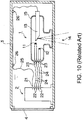
- FIG. 10 is a schematic diagram of such an existing X-ray generation device.
- the X-ray generation device has a structure that an X-ray tube 1 and a high voltage generation part 2 are accommodated in a chamber formed by a housing 3 and a lid body 4. Insulating oil is filled in the chamber formed by the housing 3 and the lid body 4.
- the X-ray tube 1 includes a glass tube 15 and a plurality of terminals 23 arranged across the interior and exterior of the glass tube 15. Besides, a filament 11, a heater 12, and a target 13 are arranged inside the glass tube 15. Here, the filament 11 is used to emit an electron beam toward the target 13. The electron beam emitted from the filament 11 collides with the target 13 to generate X-ray. The X-ray is irradiated toward the outside of the X-ray tube 1 from an X-ray irradiating part 14.
- the heater 12 is also called as a getter, and is used to adsorb gas molecules inside the glass tube 15.
- the target 13 is connected to a terminal 21 in the high voltage generation part 2 via a flexible cable 25 which is a single-core wire, and is applied with a positive high voltage accelerating electron beam from the high voltage generation part 2.
- the flexible cable 25 is supported by a support member 26 arranged on a ceiling part of the housing 3.
- the terminals 23 in the X-ray tube 1 connected with the filament 11 and the heater 12 are connected to terminals 22 in the high voltage generation part 2 via flexible cables 24 which are single-core wires.
- a filament current is applied to the filament 11 from the high voltage generation part 2 via the terminals 22, the flexible cables 24 and the terminals 23.
- a heater current is applied to the heater 12 from the high voltage generation part 2 via the terminals 22, the flexible cables 24 and the terminals 23.
- the flexible cables 24 and each terminal 22, 23 are usually connected by a solder.
- the length of the flexible cables 24 shall be above a specific length.
- Patent literature 1 Japanese Laid-open No. 2009-176462
- a solution of connecting the flexible cables 24 and each terminal 22, 23 by riveting is also considered.
- the flexible cables 24 and each terminal 22, 23 are directly connected by riveting, the flexible cable 24 and each terminal 22, 23 cannot be detached.
- the X-ray tube 1 is a consumable in the X-ray generation device, thus it is necessary to replace the X-ray tube after a specific time; therefore, when the flexible cables 24 and each terminal 22, 23 cannot be detached, the replacement of the X-ray tube 1 is obstructed.
- One of the embodiments of the present disclosure is accomplished to solve the abovementioned problems, and aims to provide an X-ray generation device, an X-ray fluoroscopic image photographing device and a CT image photographing device; the X-ray generation device is capable of facilitating the electrical connection of terminals of an X-ray tube to terminals of a high voltage generation part, capable of preventing wiring bodies which connect these terminals from contacting with each other, and capable of preventing the wiring bodies from separating from the terminals of the X-ray tube or the terminals of the high voltage generation part.
- An embodiment of the disclosure provides an X-ray generation device, which includes: an X-ray tube; a high voltage generation part, which applies a high voltage to the X-ray tube; and a wiring body, which connects terminals in the X-ray tube to terminals in the high voltage generation part; the wiring body is formed by a conductive bar-shaped member having stiffness, which includes a connecting part that is connected to the terminals in the X-ray tube at one end, and includes a connecting part that is connected to the terminals in the high voltage generation part at the other end.
- a metallic bar-shaped member is used as the conductive bar-shaped member.
- a contact socket is arranged at an end of the bar-shaped member.
- a contact socket is arranged at an end of the bar-shaped member, and a contact plug is arranged on the terminal in the X-ray tube or the terminal in the high voltage generation part.
- a contact plug is arranged at an end of the bar-shaped member, and a contact socket is arranged on the terminal in the X-ray tube or the terminal in the high voltage generation part.
- the bar-shaped member is a tubular member capable of being connected to the terminal in the X-ray tube and the terminal in the high voltage generation part.
- the terminals in the X-ray tube and the terminals in the high voltage generation part are accommodated in a chamber, and an interior of the chamber is filled with insulating oil.
- the terminals in the X-ray tube and the terminals in the high voltage generation part are accommodated in a chamber, and an interior of the chamber is filled with an insulating gas.
- the terminals in the X-ray tube and the terminals in the high voltage generation part are accommodated in a chamber, and an interior of the chamber is set to a high-vacuum state.
- the X-ray tube includes terminals arranged in the chamber and a target protruding outside from the chamber, the target is connected to ground, the high voltage generation part has a lid body structure closing the chamber, and the terminals in the high voltage generation part supply a minus voltage to the terminals in the X-ray tube.
- An embodiment of the disclosure provides an X-ray fluoroscopic image photographing device which uses the X-ray generation device.
- An embodiment of the disclosure provides a CT image photographing device which uses the X-ray generation device.
- the electrical connection of the terminals of the X-ray tube and the terminals of the high voltage generation part can be easily performed, and the wiring body connecting these terminals can be prevented from contacting with each other. Moreover, even if special locking mechanism is not used, the wiring body can be prevented from separating from the terminals of the X-ray tube or the terminal s of the high voltage generation part.
- the device structure can be simplified, and wirings for applying a target voltage to the X-ray tube can be removed.
- FIG. 1 is a schematic diagram of an X-ray generation device according to a first embodiment of the present disclosure.
- the X-ray generation device of the present disclosure has a structure which accommodates an X-ray tube 1 and a high voltage generation part 2 in a chamber formed by a housing 3 and a lid body 4.
- the interior of the chamber formed by the housing 3 and the lid body 4 is filled with insulating oil. Accordingly, the interior of the chamber formed by the housing 3 and the lid body 4 and the high voltage generation part 2 can be set an insulating state.
- the interior of the chamber may also be set to the insulating state by filling the interior of the chamber with an insulating gas or setting the interior of the chamber to a high-vacuum state instead of using insulating oil.
- the X-ray tube 1 includes a glass tube 15 and a plurality of terminal 23 arranged across the interior and exterior of the glass tube 15. Besides, a filament 11, a heater 12, and a target 13 are arranged inside the glass tube 15. Here, the filament 11 is used to emit an electron beam toward the target 13. The electron beam emitted from the filament 11 generates an X-ray by colliding with the target 13. The X-ray is irradiated from an X-ray irradiating part 14 toward the exterior of the X-ray tube 1. Besides, the heater 12 is also called as a getter, and is used to adsorb gas molecules inside the glass tube 15.
- the target 13 is connected to terminals 21 in the high voltage generation part 2 via flexible cables 25 which are single-core wires, and is applied with a positive high voltage for accelerating the electron beam from the high voltage generation part 2.
- the flexible cables 25 are supported by a support member 26 arranged on a ceiling part of the housing 3.
- the terminals 23 in the X-ray tube 1 which are connected to the filament 11 and the heater 12 are connected to the terminals 22 in the high voltage generation part 2 via a wiring body 70 which includes a conductive bar-shaped member 80 (see FIG. 2 ) having stiffness.
- the filament 11 is applied with a filament current by the high voltage generation part 2 via the terminals 22, the wiring body 70 and the terminals 23.
- the heater 12 is applied with a heater current by the high voltage generation part 2 via the terminals 22, and the terminals 23.
- a length of the wiring body 70 corresponds to a distance between the terminals 22 and the terminals 23.
- FIG. 2 is an enlarged diagram illustrating the wiring body 70 along with the terminals 22, 23.
- the wiring body 70 includes the conductive bar-shaped member 80 having stiffness, and contact sockets 81 arranged at two ends of the bar-shaped member 80.
- the socket 81 is fixed to the bar-shaped member 80 using a riveting part 82.
- Each socket 81 is electrically connected to the terminal 22 and the terminal 23 which function as a contact plug respectively. Therefore, the internal diameter of a recess formed on each socket 81 is consistent with the external diameter of the terminal 22 and the terminal 23.
- the conductive bar-shaped member 80 for example, among metallic members, a Kovar alloy which blends nickel and cobalt in iron can be used.
- the weight percent at the moment is, for example, 53% of iron, 29% of nickel and 17% of cobalt.
- the socket 81 in the wiring body 70 shown in FIG. 2 is engaged with each terminal 23 in the X-ray tube 1 fixed inside the housing 3.
- dispose the high voltage generation part 2 in the housing 3 engage each terminal 22 with the socket 81 in the wiring body 70, and then fix the high voltage generation part 2 to the housing 3.
- each wiring body 70 has stiffness, even in a case when holding members and so on are not used, contact between each wiring body 70 can be prevented. Furthermore, because each wiring body 70 has stiffness, the socket 81 at the end of each wiring body 70 can be prevented from separating from the terminal 22 or the terminal 23.
- the terminals 21 in the high voltage generation part 2 may also be connected to the target 13 via a conductive bar-shaped member which is similar to the wiring body 70 and has stiffness.
- FIG. 3 is a schematic diagram of an X-ray generation device according to a second embodiment of the present disclosure.
- the members similar to those in the first embodiment are denoted with the same symbols and detailed description is omitted.
- the X-ray generation device of the second embodiment has a structure that the high voltage generation part 2 is fixed to the lid body 4 which forms the chamber along with the housing 3.
- the lid body 4 when the lid body 4 is fixed to the housing 3, each terminal 22 in the high voltage generation part 2 can be engaged with the socket 81 in the wiring body 70.
- FIG. 4 is a schematic diagram of an X-ray generation device according to a third embodiment of the present disclosure.
- the members similar to those in the first and second embodiment are denoted with the same symbols and detailed description is omitted.
- the X-ray tube 1 includes the terminals 23 arranged in the chamber formed by the housing 3 and the lid body 4, and the target 13 protruding outside from the chamber; and the target 13 is connected to ground via the housing 3. Moreover, the terminals 22 in the high voltage generation part 2 supply a minus voltage to the terminals 23 in the X-ray tube 1 via the wiring body 70. Therefore, in the X-ray generation device of the third embodiment, a wiring for applying a target voltage to the X-ray tube 1 can be omitted.
- FIG. 5 is a schematic diagram of an X-ray generation device according to a fourth embodiment of the present disclosure.
- the members similar to those in the third embodiment are denoted with the same symbols and detailed description is omitted.
- the X-ray tube 1 includes the terminals 23 arranged in the chamber formed by the housing 3 and the lid body 4, and the target 13 protruding outside from the chamber; and the target 13 is connected to ground via the housing 3.
- the terminals 22 in the high voltage generation part 2 supply a minus voltage to the terminals 23 in the X-ray tube 1 via the wiring body 70.
- the high voltage generation part 2 has a lid body structure which closes the housing 3 forming the chamber.
- a wiring for applying a target voltage to the X-ray tube 1 can be omitted.
- the high voltage generation part 2 doubling as a lid body the device structure can be simplified.
- FIG. 6 is an enlarged diagram illustrating a wiring body 71 of a second embodiment along with the terminals 22, 23.
- the wiring body 70 shown in FIG. 2 includes the conductive bar-shaped member 80 having stiffness and the contact sockets 81 arranged at two ends of the bar-shaped member 80.
- the wiring body 71 of the second embodiment is formed by a conductive tubular member 83 having stiffness.
- the tubular member 83 is formed by the same Kovar alloy as the bar-shaped member 80 in the wiring body 70 shown in FIG. 2 .
- the internal diameter of the tubular member 83 is consistent with the external diameter of the terminal 22 and the terminal 23.
- the terminals 22 in the high voltage generation part 2 and the terminals 23 in the X-ray tube 1 can be electrically connected by an extremely simple structure without using the socket 81.
- FIG. 7 is an enlarged diagram illustrating a wiring body 72 of a third embodiment along with the terminals 22, 23.
- the wiring body 72 is formed by a conductive bar-shaped member 84 having stiffness.
- the bar-shaped member 84 is formed by the same Kovar alloy as the bar-shaped member 80 in the wiring body 70 shown in FIG. 2 .
- contact sockets 85 are fixed to the terminals 22 in the high voltage generation part 2 and the terminals 23 in the X-ray tube 1 using riveting parts 86.
- Each socket 85 is electrically connected to the end of the bar-shaped member 84 which functions as a contact plug. Therefore, the internal diameter of a recess formed on each socket 85 is consistent with the external diameter of the bar-shaped member 84.
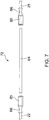
- FIG. 8 is an enlarged diagram illustrating a wiring body 73 of a fourth embodiment along with the terminals 22, 23 and so on.
- the wiring body 73 includes a conductive bar-shaped member 88 having stiffness, and contact plugs 91 arranged at two ends of the bar-shaped member 88.
- the bar-shaped member 88 is formed by the same Kovar alloy as the bar-shaped member 80 in the wiring body 70 shown in FIG. 2 .
- the plugs 91 are fixed to the bar-shaped member 88 using riveting parts 92.
- the contact sockets 85 are fixed to the terminals 22 in the high voltage generation part 2 and the terminals 23 in the X-ray tube 1 using riveting parts 86.
- Each socket 85 is electrically connected to the plug 91 fixed at the two ends of the bar-shaped member 88. Therefore, the internal diameter of a recess formed on each socket 85 is consistent with the external diameter of each plug 91. However, the external diameters of a pair of plugs 91 may be different on the left and right of the bar-shaped member 88.
- FIG. 9 is an enlarged diagram illustrating the wiring body 70 in such an embodiment along with the terminals 22, 23 and so on.
- the wiring body 70 has a structure which is the same as the first embodiment shown in FIG. 2 .
- contact plugs 87 are fixed to the terminals 22 in the high voltage generation part 2 and the terminals 23 in the X-ray tube 1 using riveting parts 89.
- Each plug 87 is electrically connected to the socket 81 fixed at the two ends of the bar-shaped member 80. Therefore, the internal diameter of a recess formed on each socket 81 is consistent with the external diameter of each plug 87. However, the external diameter of a pair of plugs 87 may be different on the left and right of the bar-shaped member 80.
- the structure is employed in which contact plugs or sockets are attached to the bar-shaped member 80, 88, and the terminals 22 in the high voltage generation part 2 or the terminals 23 in the X-ray tube 1.
- the electrical connection by the contact can be more reliable.
- the plurality of wiring bodies 70, 71, 72, 73 used in the X-ray generation device of the present disclosure have the same length; however, by changing the distance between the terminals 22 in the high voltage generation part 2 and the terminals 23 in the X-ray tube 1, wiring bodies with lengths different from each other may be used as the plurality of wiring bodies 70, 71, 72, 73.
- the X-ray generation device of the present disclosure having the abovementioned structure can be applied to an X-ray fluoroscopic photographing device or CT photographing device. Accordingly, an X-ray fluoroscopic image or a CT image can be preferably photographed.
Landscapes
- Health & Medical Sciences (AREA)
- Analytical Chemistry (AREA)
- General Physics & Mathematics (AREA)
- Nuclear Medicine, Radiotherapy & Molecular Imaging (AREA)
- Radiology & Medical Imaging (AREA)
- Physics & Mathematics (AREA)
- Life Sciences & Earth Sciences (AREA)
- Chemical & Material Sciences (AREA)
- Engineering & Computer Science (AREA)
- Pathology (AREA)
- Biochemistry (AREA)
- General Health & Medical Sciences (AREA)
- Immunology (AREA)
- Multimedia (AREA)
- Pulmonology (AREA)
- Theoretical Computer Science (AREA)
- X-Ray Techniques (AREA)
- Apparatus For Radiation Diagnosis (AREA)
- Analysing Materials By The Use Of Radiation (AREA)
Applications Claiming Priority (1)
| Application Number | Priority Date | Filing Date | Title |
|---|---|---|---|
| JP2017173768A JP2019050123A (ja) | 2017-09-11 | 2017-09-11 | X線発生装置、x線透視像撮影装置およびct像撮影装置 |
Publications (2)
| Publication Number | Publication Date |
|---|---|
| EP3454356A2 true EP3454356A2 (de) | 2019-03-13 |
| EP3454356A3 EP3454356A3 (de) | 2019-06-12 |
Family
ID=63405015
Family Applications (1)
| Application Number | Title | Priority Date | Filing Date |
|---|---|---|---|
| EP18190618.1A Withdrawn EP3454356A3 (de) | 2017-09-11 | 2018-08-24 | Röntgenerzeugungsvorrichtung, röntgendurchleuchtungsbildaufnahmevorrichtung und ct-bildaufnahmevorrichtung |
Country Status (4)
| Country | Link |
|---|---|
| US (1) | US10631391B2 (de) |
| EP (1) | EP3454356A3 (de) |
| JP (1) | JP2019050123A (de) |
| CN (1) | CN109494144A (de) |
Families Citing this family (1)
| Publication number | Priority date | Publication date | Assignee | Title |
|---|---|---|---|---|
| EP4364178A1 (de) | 2021-06-30 | 2024-05-08 | Varex Imaging Corporation | Vakuumröhreneinsatzanordnung mit durchführungsstiftstecker und gegenbuchse |
Citations (1)
| Publication number | Priority date | Publication date | Assignee | Title |
|---|---|---|---|---|
| JP2009176462A (ja) | 2008-01-22 | 2009-08-06 | Hitachi Medical Corp | X線発生装置 |
Family Cites Families (13)
| Publication number | Priority date | Publication date | Assignee | Title |
|---|---|---|---|---|
| FR543577A (fr) * | 1921-11-15 | 1922-09-05 | Appareil radiologique de grande puissance | |
| GB1147805A (en) * | 1966-07-25 | 1969-04-10 | Sp Kb Rentgenovskoi Apparatury | A portable pulse x-ray device |
| JPS51150072U (de) * | 1975-05-26 | 1976-12-01 | ||
| JP2750348B2 (ja) * | 1988-04-08 | 1998-05-13 | シーメンス、アクチエンゲゼルシヤフト | 特にガスレーザーのx線‐前期電離のためのプラズマx線管、および電子銃としての用途 |
| DE19621528A1 (de) * | 1996-05-29 | 1997-12-04 | Philips Patentverwaltung | Röntgeneinrichtung |
| JP3382104B2 (ja) * | 1996-11-21 | 2003-03-04 | 株式会社東芝 | X線装置 |
| FR2809277B1 (fr) * | 2000-05-19 | 2002-08-23 | Ge Med Sys Global Tech Co Llc | Dispositif d'emission de rayons x et procede de montage |
| US7448801B2 (en) * | 2002-02-20 | 2008-11-11 | Inpho, Inc. | Integrated X-ray source module |
| CN1751543B (zh) * | 2003-02-20 | 2011-02-02 | 因普有限公司 | 集成的x射线源模块 |
| WO2007043395A1 (ja) * | 2005-10-07 | 2007-04-19 | Hamamatsu Photonics K.K. | X線管及びそれを含むx線源 |
| EP2740331B1 (de) * | 2011-08-05 | 2018-05-30 | Canon Kabushiki Kaisha | Strahlungserzeugungsgerät und strahlungsbildgebungsgerät |
| US8855270B2 (en) * | 2012-03-06 | 2014-10-07 | General Electric Company | Antiwetting coating for liquid metal bearing and method of making same |
| US10743773B2 (en) * | 2012-05-02 | 2020-08-18 | Koninklijke Philips N.V. | Imaging thermometry |
-
2017
- 2017-09-11 JP JP2017173768A patent/JP2019050123A/ja active Pending
-
2018
- 2018-08-24 EP EP18190618.1A patent/EP3454356A3/de not_active Withdrawn
- 2018-08-30 CN CN201811005709.5A patent/CN109494144A/zh not_active Withdrawn
- 2018-09-03 US US16/120,320 patent/US10631391B2/en not_active Expired - Fee Related
Patent Citations (1)
| Publication number | Priority date | Publication date | Assignee | Title |
|---|---|---|---|---|
| JP2009176462A (ja) | 2008-01-22 | 2009-08-06 | Hitachi Medical Corp | X線発生装置 |
Also Published As
| Publication number | Publication date |
|---|---|
| CN109494144A (zh) | 2019-03-19 |
| EP3454356A3 (de) | 2019-06-12 |
| US20190082524A1 (en) | 2019-03-14 |
| US10631391B2 (en) | 2020-04-21 |
| JP2019050123A (ja) | 2019-03-28 |
Similar Documents
| Publication | Publication Date | Title |
|---|---|---|
| US10734188B2 (en) | X-ray tube for improving electron focusing | |
| US8224448B2 (en) | Feedthrough assembly including sleeve | |
| US9839346B2 (en) | Surgical instrument | |
| US11232926B2 (en) | Cathode for an X-ray tube | |
| CN105990077B (zh) | X射线管 | |
| CN106252184A (zh) | X射线管 | |
| JP5155133B2 (ja) | 電気リードスルーモジュール及びそれを製造する方法 | |
| US20180006389A1 (en) | Electrical connection piece for an endoscope and method for establishing an electrical connection in an endoscope | |
| US10631391B2 (en) | X-ray generation device, X-ray fluoroscopic image photographing device and CT image photographing device | |
| WO2017199756A1 (ja) | 信号端子とグランド端子を備えた電気コネクタ、及び、これを用いた電気コネクタ装置 | |
| US10349505B2 (en) | High-voltage supply and an x-ray emitter having the high-voltage supply | |
| CN110071026A (zh) | X射线发生装置及x射线摄影装置 | |
| WO2018016319A1 (ja) | 端子金具およびそれを用いた配線モジュール | |
| RU2643171C2 (ru) | Узел электрического разъема | |
| CN107420787A (zh) | 带基座的灯单元 | |
| US6607416B2 (en) | Method and apparatus for setting X-ray tube filaments | |
| JP2008226783A (ja) | X線発生器及びx線装置 | |
| US20250079110A1 (en) | High-voltage x-ray tank with miniaturized shielding structure | |
| CN115398589B (zh) | 电子束产生源、电子束照射装置和x射线照射装置 | |
| JP2004047129A (ja) | 中継プラグ、コネクタ、及びx線発生装置 | |
| JP2010080348A (ja) | X線管装置 | |
| CN214542113U (zh) | 用于x射线管的电子释放源、阴极装置及x射线装置 | |
| KR20200036325A (ko) | 이온화 장치 | |
| GB2107110A (en) | Discharge lamps | |
| JP2024527321A (ja) | フィードスルーピンプラグ及び嵌合ソケット付きの真空管挿入アセンブリ |
Legal Events
| Date | Code | Title | Description |
|---|---|---|---|
| PUAI | Public reference made under article 153(3) epc to a published international application that has entered the european phase |
Free format text: ORIGINAL CODE: 0009012 |
|
| STAA | Information on the status of an ep patent application or granted ep patent |
Free format text: STATUS: THE APPLICATION HAS BEEN PUBLISHED |
|
| AK | Designated contracting states |
Kind code of ref document: A2 Designated state(s): AL AT BE BG CH CY CZ DE DK EE ES FI FR GB GR HR HU IE IS IT LI LT LU LV MC MK MT NL NO PL PT RO RS SE SI SK SM TR |
|
| AX | Request for extension of the european patent |
Extension state: BA ME |
|
| PUAL | Search report despatched |
Free format text: ORIGINAL CODE: 0009013 |
|
| AK | Designated contracting states |
Kind code of ref document: A3 Designated state(s): AL AT BE BG CH CY CZ DE DK EE ES FI FR GB GR HR HU IE IS IT LI LT LU LV MC MK MT NL NO PL PT RO RS SE SI SK SM TR |
|
| AX | Request for extension of the european patent |
Extension state: BA ME |
|
| RIC1 | Information provided on ipc code assigned before grant |
Ipc: H05G 1/06 20060101ALI20190509BHEP Ipc: G01N 23/046 20180101ALI20190509BHEP Ipc: H05G 1/08 20060101ALI20190509BHEP Ipc: H01J 35/08 20060101AFI20190509BHEP Ipc: G01N 23/04 20180101ALI20190509BHEP Ipc: H01J 35/14 20060101ALI20190509BHEP Ipc: H05G 1/02 20060101ALI20190509BHEP Ipc: H05G 1/10 20060101ALI20190509BHEP |
|
| STAA | Information on the status of an ep patent application or granted ep patent |
Free format text: STATUS: REQUEST FOR EXAMINATION WAS MADE |
|
| 17P | Request for examination filed |
Effective date: 20191025 |
|
| RBV | Designated contracting states (corrected) |
Designated state(s): AL AT BE BG CH CY CZ DE DK EE ES FI FR GB GR HR HU IE IS IT LI LT LU LV MC MK MT NL NO PL PT RO RS SE SI SK SM TR |
|
| STAA | Information on the status of an ep patent application or granted ep patent |
Free format text: STATUS: EXAMINATION IS IN PROGRESS |
|
| 17Q | First examination report despatched |
Effective date: 20200210 |
|
| STAA | Information on the status of an ep patent application or granted ep patent |
Free format text: STATUS: THE APPLICATION HAS BEEN WITHDRAWN |
|
| 18W | Application withdrawn |
Effective date: 20200422 |