EP3453866B1 - Montagesystem zum aufbringen eines dichtringes - Google Patents
Montagesystem zum aufbringen eines dichtringes Download PDFInfo
- Publication number
- EP3453866B1 EP3453866B1 EP18193389.6A EP18193389A EP3453866B1 EP 3453866 B1 EP3453866 B1 EP 3453866B1 EP 18193389 A EP18193389 A EP 18193389A EP 3453866 B1 EP3453866 B1 EP 3453866B1
- Authority
- EP
- European Patent Office
- Prior art keywords
- injector
- sealing ring
- pushing
- bore
- mounting element
- Prior art date
- Legal status (The legal status is an assumption and is not a legal conclusion. Google has not performed a legal analysis and makes no representation as to the accuracy of the status listed.)
- Active
Links
- 238000007789 sealing Methods 0.000 title claims description 42
- 230000007480 spreading Effects 0.000 claims description 4
- 238000000034 method Methods 0.000 claims description 3
- 239000013013 elastic material Substances 0.000 claims description 2
- 238000009434 installation Methods 0.000 claims 19
- 238000002347 injection Methods 0.000 description 6
- 239000007924 injection Substances 0.000 description 6
- 230000035515 penetration Effects 0.000 description 4
- 239000000446 fuel Substances 0.000 description 3
- 238000002485 combustion reaction Methods 0.000 description 2
- 230000008859 change Effects 0.000 description 1
- 230000001419 dependent effect Effects 0.000 description 1
- 238000001746 injection moulding Methods 0.000 description 1
- 239000000463 material Substances 0.000 description 1
- 230000007246 mechanism Effects 0.000 description 1
- 230000007704 transition Effects 0.000 description 1
Images


Classifications
-
- F—MECHANICAL ENGINEERING; LIGHTING; HEATING; WEAPONS; BLASTING
- F02—COMBUSTION ENGINES; HOT-GAS OR COMBUSTION-PRODUCT ENGINE PLANTS
- F02M—SUPPLYING COMBUSTION ENGINES IN GENERAL WITH COMBUSTIBLE MIXTURES OR CONSTITUENTS THEREOF
- F02M61/00—Fuel-injectors not provided for in groups F02M39/00 - F02M57/00 or F02M67/00
- F02M61/14—Arrangements of injectors with respect to engines; Mounting of injectors
-
- B—PERFORMING OPERATIONS; TRANSPORTING
- B25—HAND TOOLS; PORTABLE POWER-DRIVEN TOOLS; MANIPULATORS
- B25B—TOOLS OR BENCH DEVICES NOT OTHERWISE PROVIDED FOR, FOR FASTENING, CONNECTING, DISENGAGING OR HOLDING
- B25B27/00—Hand tools, specially adapted for fitting together or separating parts or objects whether or not involving some deformation, not otherwise provided for
- B25B27/0028—Tools for removing or installing seals
-
- F—MECHANICAL ENGINEERING; LIGHTING; HEATING; WEAPONS; BLASTING
- F02—COMBUSTION ENGINES; HOT-GAS OR COMBUSTION-PRODUCT ENGINE PLANTS
- F02M—SUPPLYING COMBUSTION ENGINES IN GENERAL WITH COMBUSTIBLE MIXTURES OR CONSTITUENTS THEREOF
- F02M61/00—Fuel-injectors not provided for in groups F02M39/00 - F02M57/00 or F02M67/00
- F02M61/16—Details not provided for in, or of interest apart from, the apparatus of groups F02M61/02 - F02M61/14
- F02M61/168—Assembling; Disassembling; Manufacturing; Adjusting
-
- F—MECHANICAL ENGINEERING; LIGHTING; HEATING; WEAPONS; BLASTING
- F16—ENGINEERING ELEMENTS AND UNITS; GENERAL MEASURES FOR PRODUCING AND MAINTAINING EFFECTIVE FUNCTIONING OF MACHINES OR INSTALLATIONS; THERMAL INSULATION IN GENERAL
- F16J—PISTONS; CYLINDERS; SEALINGS
- F16J15/00—Sealings
- F16J15/16—Sealings between relatively-moving surfaces
- F16J15/32—Sealings between relatively-moving surfaces with elastic sealings, e.g. O-rings
- F16J15/3268—Mounting of sealing rings
-
- F—MECHANICAL ENGINEERING; LIGHTING; HEATING; WEAPONS; BLASTING
- F02—COMBUSTION ENGINES; HOT-GAS OR COMBUSTION-PRODUCT ENGINE PLANTS
- F02M—SUPPLYING COMBUSTION ENGINES IN GENERAL WITH COMBUSTIBLE MIXTURES OR CONSTITUENTS THEREOF
- F02M2200/00—Details of fuel-injection apparatus, not otherwise provided for
- F02M2200/85—Mounting of fuel injection apparatus
- F02M2200/858—Mounting of fuel injection apparatus sealing arrangements between injector and engine
-
- F—MECHANICAL ENGINEERING; LIGHTING; HEATING; WEAPONS; BLASTING
- F02—COMBUSTION ENGINES; HOT-GAS OR COMBUSTION-PRODUCT ENGINE PLANTS
- F02M—SUPPLYING COMBUSTION ENGINES IN GENERAL WITH COMBUSTIBLE MIXTURES OR CONSTITUENTS THEREOF
- F02M2200/00—Details of fuel-injection apparatus, not otherwise provided for
- F02M2200/90—Selection of particular materials
- F02M2200/9015—Elastomeric or plastic materials
Definitions
- the invention relates to an assembly system for applying a sealing ring to a fuel injector.
- Fuel injectors (high-pressure injection valves) often have a sealing ring in order to seal the interface between the injector and the housing of a combustion chamber into which the fuel injector has been introduced in a gas-tight manner.
- the sealing ring is a wearing part that must be replaced every time the injector is moved, especially when the injector is pulled out of its position in the combustion chamber.
- Mounting systems for applying a sealing ring are known from US 2003/097744 A1 , US 2005/109325 A1 , DE 100 22 383 A1 and US 2004/194277 .
- Embodiments of the invention also include an assembly system for applying a sealing ring to an injector according to claim 1.
- a method for applying a sealing ring to an injector with such a mounting system comprises applying a sealing ring to the first region of the mounting element; apply the mounting element to the injector; to push the sliding device onto the mounting element in such a way that the mounting element penetrates the bore and the sliding device pushes the sealing ring over the conical area and the second cylindrical area of the mounting element onto an area of the injector; and pulling the sliding device off the mounting element.
- the depth of penetration of the mounting element into the bore is limited by the stop to a predetermined amount which cannot be exceeded.
- a sealing ring to be mounted is pushed to its final position on the injector when the sliding device is pushed onto the mounting element as far as it will go. The assembly and in particular the exact positioning of the sealing ring are thereby considerably simplified.
- the penetration depth specified by the stop is precisely matched to the mounting element.
- the penetration depth through the stop is limited to 2.5 cm to 3 cm, in particular to 2.79 cm.
- Penetration depths of 2.5 cm to 3 cm correspond to the usual mounting positions for sealing rings on injectors.
- the housing of the sliding device is made of plastic.
- a plastic housing is lightweight and can be manufactured inexpensively, for example in an injection molding process.
- the outer end of the bore is surrounded by elastic expansion elements, in particular three elastic expansion elements.
- the expansion elements can spread apart and thus change the diameter of the hole in order to adapt the hole to different diameters of the Adapt mounting element. This ensures that the axial contact surface of the sealing ring on the expansion elements is always at its maximum.
- an ejector pin is present at the inner end of the bore, which is designed to press a mounting element arranged in the bore in the direction of the open end of the bore. In this way, it is prevented that the mounting element remains undesirably in the bore, and the push-on device can be easily separated from the mounting element.
- the ejector pin is elastically mounted, in particular by a (spiral) spring.
- a (spiral) spring In this way, the ejector pin can be displaced against the force of the spring when the push-on device is applied to the mounting element.
- the mounting element is pushed out of the bore by the elastic force of the spring when the push-on device is removed from the injector.
- the mounting element has a first cylindrical area which has a first diameter, a second cylindrical area which has a second diameter which is larger than the first diameter, and a conical area which is arranged between the first and the second cylindrical area and which connects the two cylindrical areas to one another.
- the first and the second cylindrical area and the conical area are in particular arranged coaxially on a common axis.
- the first diameter is chosen so that the sealing ring can be easily pushed onto the mounting element.
- the first diameter thus corresponds approximately to the inner diameter of the sealing ring in its non-expanded initial state.
- the second diameter is selected so that only a very small wall thickness of the second cylindrical area of the mounting element is added to the outer diameter of the injector. Such a strong expansion of the sealing ring is prevented in this way.
- FIGS. 1 to 6 illustrate the use of a push-on device 10 according to the invention for applying a sealing ring 4 to an injector 6.
- the Figure 1 shows a mounting element 2 with a first, cylindrical area 2a, shown on the right, a second, hollow cylindrical area 2b, shown on the left.
- the first cylindrical area 2a and the second cylindrical area 2b are arranged coaxially on a common axis A.
- the second cylindrical area 2b has a larger diameter d2 than the first cylindrical area 2a.
- the first and the second cylindrical area 2a, 2c are connected to one another by a hollow conical area 2b which widens from the diameter d1 of the first cylindrical area 2a to the diameter d2 of the second cylindrical area 2c.
- the Figure 2 shows that in the Figure 1 Mounting element 2 shown with a sealing ring 4 applied to mounting element 2, which is pushed onto mounting element 2 up to the transition from first cylindrical area 2a to conical area 2b.
- FIG Figure 3 shows an injector 6 with a cylindrical injection-side region 7, on which a calibration ring 8 and a mounting element 2 with the sealing ring 4, as shown in FIG Figure 2 shown are postponed.
- a denotes the length of the overlap between the mounting element 2 and the cylindrical injection-side region 7 of the injector 6.
- the Figure 4 illustrates how the sealing ring 4 is pushed onto the cylindrical injection-side area 7 of the injector 6 by applying a sliding device 10 according to the invention over the conical area 2b and the second cylindrical area 2c of the mounting element 2.
- An end face 11 of the application device 10 facing the injector 6 comes into contact with the sealing ring 4 and pushes the sealing ring 4 over the conical area 2b and the second cylindrical area 2c of the assembly device 2 onto the cylindrical injection-side area 7 of the injector 6.
- the push-on device 10 is removed by removing it from the area of the injector 6 on the injection side (in the illustration of FIG Figures 3 to 5 to the right) will be withdrawn.
- the mounting element 2 is pressed out of the slide-on device 10 by a spring mechanism described below, so that it initially remains on the injection-side area of the injector 6 and is pulled off separately.
- the calibration ring 8 is pulled off the injector 6 with a rotary movement of approximately 180 ° around a longitudinal axis C of the injection-side region 7 of the injector 6.
- the sealing ring 4 is calibrated and fixed in the correct position of the injection-side area 7 of the injector 6, so that the in the Figure 6
- the final configuration of the injector 6 shown with a sealing ring 4 mounted on the injection-side area 7 results.
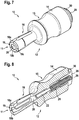
- FIG. 7 shows a perspective external view of a slide-on device 10 according to an exemplary embodiment of the invention.
- Figure 8 FIG. 10 shows a perspective sectional view of the slide-on device 10 and
- FIG. 13 shows a planar sectional view of that in FIG Figures 7 and 8 sliding device 10 shown.
- the sliding device 10 has a substantially rotationally symmetrical housing 12 with a rear (shown on the right) grip area 14, 15 and a front (shown on the left) sliding area 16.
- the grip area 14, 15 has a larger diameter D3 than the sliding area 16 and is ergonomic Recessed grip 15 is formed.
- the housing 12 has, for example, a maximum diameter D3 of approximately 25 mm.
- the sliding area 16 comprises three expansion elements 18a, 18b and 18c which are arranged around a central bore 20, which extends along the longitudinal axis B of the sliding device 10, in such a way that they are in the in the Figure 7 shown relaxed state abut one another and enclose the bore 20 in a cylindrical shape.
- the outer diameter D2 of the sliding area 16 is approximately 12 mm.
- the diameter D1 of the central bore 20 is dependent on the outer diameter d2 of the mounting element 2 and the area 7 of the injector 6 on the injection side and is usually between 5 and 7 mm, e.g. 5.35 mm or 6.35 mm.
- the central bore 20 has an open front end (mouth) 19 and is limited at its rear end within the housing 12 by a stop 21.
- the mounting element 2 strikes the stop 21 when the Sliding device 10 is pushed onto the mounting element 2, as shown in FIG Figure 4 is shown.
- the distance L1 between the open outer end 19 of the bore 20 and the stop 21 thus specifies the length of the distance that the sliding device 10 can be pushed onto the mounting element 2 until the mounting element 2 strikes the stop 21. It thus also specifies the position on the cylinder-shaped region 7 of the injector 6 on the injection side, at which the sealing ring 4 is located after the sliding device 10 has been pushed onto the mounting element 2 as far as the stop 21.
- the expansion elements 18a, 18b, 18c are spread apart.
- the spreading increases the diameter of the central bore 20, and the sliding area 16 of the sliding device 10 can be pushed via the conical area 2b onto the second cylindrical area 2c of the mounting element 2, which has a larger diameter D2 than the first cylindrical area 2a.
- the housing 12 of the sliding device 10 is made of an elastic material, in particular a plastic, which enables the described elastic spreading of the spreading elements 18a, 18b, 18c.
- a hollow spring chamber 24 is formed on the side of the stop 21 facing away from the central bore 20.
- a spiral spring 26 is arranged in the spring chamber 24 in such a way that it presses an ejector pin 22 through an opening formed in the stop 21 into the central bore 20.
- the ejector pin 22 has, for example, a length L2 of 15 to 17 mm, in particular a length L2 of 16.4 mm.
- a (rear) end of the spring 26 facing away from the central bore 20 and the ejector pin 22 is supported on a spring support element 28.
- the spring support element 28 is screwed into the spring bore 24 and places the spring 26 under a predetermined pretension.
- the spring support element 28 has a receptacle 30 for a hook wrench, which makes it easier to screw the spring support element 28 into the housing 12.
- the handling of the slide-on device 10 is simplified, since the assembly element 2 can be easily removed from the slide-on device 10.
- this prevents the mounting element 2 from being exposed to the forces of the expansion elements 18a, 18b, 18c acting inward in the radial direction which, without the supporting geometry of the injection-side region 7 of the injector 6, lead to a deformation of the mounting element 2 and thus could lead to its uselessness.
- the mounting element 2 can save material and weight with a low wall thickness.
- the sealing ring 4 is always positioned in exactly the right position on the injection-side area 7 of the injector 6.
Landscapes
- Engineering & Computer Science (AREA)
- Mechanical Engineering (AREA)
- General Engineering & Computer Science (AREA)
- Chemical & Material Sciences (AREA)
- Combustion & Propulsion (AREA)
- Manufacturing & Machinery (AREA)
- Fuel-Injection Apparatus (AREA)
Description
- Die Erfindung betrifft ein Montagesystem zum Aufbringen eines Dichtringes auf einen Kraftstoffinjektor.
- Kraftstoffinjektoren (Hochdruck-Einspritzventile) weisen häufig einen Dichtring auf, um die Schnittstelle zwischen dem Injektor und dem Gehäuse eines Verbrennungsraums, in den der Kraftstoffinjektor eingebracht worden ist, gasdicht abzudichten.
- Der Dichtring ist ein Verschleißteil, das jedes Mal ausgetauscht werden muss, wenn der Injektor bewegt wird, insbesondere wenn der Injektor aus seiner Position im Brennraum gezogen wird. Montagesystems zum Aufbringen eines Dichtringes sind bekannt aus
US 2003/097744 A1 ,US 2005/109325 A1 ,DE 100 22 383 A1 undUS 2004/194277 . - Es ist eine Aufgabe der Erfindung, das Austauschen des Dichtringes, insbesondere das Aufbringen eines neuen Dichtringes auf den Injektor, zu vereinfachen.
- Ausführungsbeispiele der Erfindung umfassen auch ein Montagesystem zum Aufbringen eines Dichtringes auf einen Injektor gemäß Anspruch 1.
- Ein Verfahren zum Aufbringen eines Dichtringes auf einen Injektor mit einem solchen Montagesystem umfasst, einen Dichtring auf den ersten Bereich des Montageelements aufzubringen; das Montageelement auf den Injektor aufzubringen; die Aufschiebevorrichtung derart auf das Montageelement aufzuschieben, dass das Montageelement in die Bohrung eindringt und die Aufschiebevorrichtung den Dichtring über den kegelförmigen Bereich und den zweiten zylindrischen Bereich des Montageelements auf einen Bereich des Injektors schiebt; und die Aufschiebevorrichtung von dem Montageelement abzuziehen.
- Durch den Anschlag wird die Eindringtiefe des Montageelements in die Bohrung auf ein vorgegebenes Maß, das nicht überschritten werden kann, begrenzt. Ein zu montierender Dichtring wird so auf seine endgültige Position auf dem Injektor geschoben, wenn die Aufschiebevorrichtung bis zum Anschlag auf das Montageelement aufgeschoben wird. Die Montage und insbesondere die exakte Positionierung des Dichtringes werden dadurch erheblich vereinfacht.
- Die durch den Anschlag vorgegebene Eindringtiefe ist exakt auf das Montageelement abgestimmt.
- In einer Ausführungsform ist die Eindringtiefe durch den Anschlag auf 2,5 cm bis 3 cm, insbesondere auf 2,79 cm begrenzt. Eindringtiefen von 2,5 cm bis 3 cm entsprechen den üblichen Montagepositionen von Dichtringen auf Injektoren.
- In einer Ausführungsform ist das Gehäuse der Aufschiebevorrichtung aus Kunststoff gefertigt. Ein Kunststoffgehäuse hat ein geringes Gewicht und kann, z.B. in einem Spritzgussverfahren, kostengünstig hergestellt werden.
- Erfindungsgemäß ist das äußere Ende der Bohrung von elastischen Spreizelementen, insbesondere von drei elastischen Spreizelementen, umgeben. Die Spreizelemente können sich aufspreizen und so den Durchmesser der Bohrung verändern, um die Bohrung an unterschiedliche Durchmesser des Montageelements anzupassen. So wird sichergestellt, dass die axiale Auflagefläche des Dichtringes an den Spreizelementen immer maximal ist.
- In einer Ausführungsform ist am inneren Ende der Bohrung ein Ausdrückstift vorhanden, der ausgebildet ist, ein in der Bohrung angeordnetes Montageelement in Richtung des offenen Endes der Bohrung zu drücken. Auf diese Weise wird verhindert, dass das Montageelement unerwünscht in der Bohrung verbleibt, und die Aufschiebevorrichtung kann gut von dem Montageelement getrennt werden.
- In einer Ausführungsform ist der Ausdrückstift, insbesondere durch eine (Spiral-) Feder, elastisch gelagert. Auf diese Weise kann der Ausdrückstift gegen die Kraft der Feder verschoben werden, wenn die Aufschiebevorrichtung auf das Montageelement aufgebracht wird. Durch die elastische Kraft der Feder wird das Montageelement aus der Bohrung geschoben, wenn die Aufschiebevorrichtung vom Injektor abgezogen wird.
- Erfindungsgemäß hat das Montageelement einen ersten zylindrischen Bereich, der einen ersten Durchmesser hat, einen zweiten zylindrischen Bereich, der einen zweiten Durchmesser hat, der größer als der erste Durchmesser ist, und einen kegelförmigen Bereich, der zwischen dem ersten und dem zweiten zylindrischen Bereich angeordnet ist und der die beiden zylindrischen Bereiche miteinander verbindet. Der erste und der zweite zylindrische Bereich und der kegelförmige Bereich sind insbesondere koaxial auf einer gemeinsamen Achse angeordnet. Durch Verschieben des Dichtringes von dem ersten zylindrischen Bereich über den kegelförmigen Bereich auf den zweiten zylindrischen Bereich wird der Dichtring auf den benötigten größeren Durchmesser aufgeweitet.
- Der erste Durchmesser ist so gewählt, dass der Dichtring gut auf das Montageelement aufgeschoben werden kann. Der erste Durchmesser entspricht also in etwa dem Innendurchmesser des Dichtringes in seinem nicht aufgeweiteten Ausgangszustand.
- Der zweite Durchmesser ist so gewählt, dass nur eine sehr geringe Wandstärke des zweiten zylindrischen Bereichs des Montageelements zum Außendurchmesser des Injektors hinzukommt. Eine so starke Aufweitung des Dichtringes wird auf diese Weise verhindert.
- Ein Ausführungsbeispiel der Erfindung wird im Folgenden unter Bezugnahme auf die beigefügten Figuren beschrieben.
-
- Die
Figur 1 zeigt ein Montageelement zum Aufschieben eines Dichtringes auf einen Injektor. - Die
Figur 2 zeigt das Montageelement ausFigur 1 mit einem auf das Montageelement aufgeschobenen Dichtring. - Die
Figur 3 zeigt das Montageelement ausFigur 2 mit einem auf das Montageelement aufgeschobenen Dichtring, wobei das Montageelement auf den einspritzseitigen Bereich eines Injektors aufgebracht ist. - Die
Figur 4 zeigt die Konfiguration ausFigur 3 mit einer Aufschiebevorrichtung gemäß einem Ausführungsbeispiel der Erfindung. - Die
Figur 5 zeigt die Konfiguration ausFigur 4 , wobei die Aufschiebevorrichtung und das Montageelement von dem Injektor entfernt worden sind. -
Figur 6 zeigt den endgültigen Zustand des Injektors mit einem auf dem einspritzseitigen Bereich des Injektors aufgebrachten Dichtring. -
Figur 7 zeigt eine perspektivische Außenansicht einer Aufschiebevorrichtung gemäß einem Ausführungsbeispiel der Erfindung. -
Figur 8 zeigt eine perspektivische Schnittansicht der Aufschiebevorrichtung. -
Figur 9 zeigt eine planare Schnittansicht der Aufschiebevorrichtung. - Die
Figuren 1 bis 6 veranschaulichen die Verwendung einer erfindungsgemäßen Aufschiebevorrichtung 10 zum Aufbringen eines Dichtringes 4 auf einen Injektor 6. - Die
Figur 1 zeigt ein Montageelement 2 mit einem ersten, rechts dargestellten, zylindrischen Bereich 2a, einem zweiten, links dargestellten, hohlen zylindrischen Bereich 2b. Der erste zylindrische Bereich 2a und der zweite zylindrische Bereich 2b sind koaxial auf einer gemeinsamen Achse A angeordnet. - Der zweite zylindrische Bereich 2b hat einen größeren Durchmesser d2 als der erste zylindrische Bereich 2a. Der erste und der zweite zylindrische Bereich 2a, 2c sind durch einen hohlen kegelförmigen Bereich 2b, der sich von dem Durchmesser d1 des ersten zylindrischen Bereichs 2a auf den Durchmesser d2 des zweiten zylindrischen Bereichs 2c aufweitet, miteinander verbunden.
- Die
Figur 2 zeigt das in derFigur 1 gezeigte Montageelement 2 mit einem auf das Montageelement 2 aufgebrachten Dichtring 4, der bis zum Übergang von dem ersten zylindrischen Bereich 2a auf den kegelförmigen Bereich 2b auf das Montageelement 2 aufgeschoben ist. -
Figur 3 zeigt einen Injektor 6 mit einem zylinderförmigen einspritzseitigen Bereich 7, auf den ein Kalibrierring 8 und ein Montageelement 2 mit dem Dichtring 4, wie es in derFigur 2 gezeigt ist, aufgeschoben sind. Dabei bezeichnet a die Länge des Überlapps zwischen dem Montageelement 2 und dem zylinderförmigen einspritzseitigen Bereich 7 des Injektors 6. - Die
Figur 4 veranschaulicht, wie der Dichtring 4 durch Aufbringen einer erfindungsgemäßen Aufschiebevorrichtung 10 über den kegelförmigen Bereich 2b und den zweiten zylindrischen Bereich 2c des Montageelements 2 auf den zylinderförmigen einspritzseitigen Bereich 7 des Injektors 6 aufgeschoben wird. Dabei tritt eine dem Injektor 6 zugewandte Stirnseite 11 der Aufbringvorrichtung 10 in Kontakt mit dem Dichtring 4 und schiebt den Dichtring 4 über den kegelförmigen Bereich 2b und den zweiten zylindrischen Bereich 2c der Montagevorrichtung 2 auf den zylinderförmigen einspritzseitigen Bereich 7 des Injektors 6. - Nachdem der Dichtring 4 auf den einspritzseitigen Bereich 7 des Injektors 6 aufgeschoben worden ist, wird die Aufschiebevorrichtung 10 entfernt, indem sie vom einspritzseitigen Bereich des Injektors 6 (in der Darstellung der
Figuren 3 bis 5 nach rechts) abgezogen werden wird. Das Montageelement 2 wird durch einen im Folgenden beschriebenen Federmechanismus aus der Aufschiebevorrichtung 10 gedrückt, so dass es zunächst auf dem einspritzseitigen Bereich des Injektors 6 verbleibt und separat abgezogen wird. - Danach wird der Kalibrierring 8 unter einer Drehbewegung von ca. 180° um eine Längsachse C des einspritzseitigen Bereichs 7 des Injektors 6 vom Injektor 6 abgezogen. Dadurch wird der Dichtring 4 kalibriert und an der richtigen Stelle des einspritzseitigen Bereichs 7 des Injektors 6 fixiert, so dass sich die in der
Figur 6 gezeigte endgültige Konfiguration des Injektors 6 mit einem auf dem einspritzseitigen Bereich 7 montierten Dichtring 4 ergibt. -
Figur 7 zeigt eine perspektivische Außenansicht einer Aufschiebevorrichtung 10 gemäß einem Ausführungsbeispiel der Erfindung.Figur 8 zeigt eine perspektivische Schnittansicht der Aufschiebevorrichtung 10 undFigur 9 zeigt eine planare Schnittansicht der in der in denFiguren 7 und 8 gezeigten Aufschiebevorrichtung 10. - Die Aufschiebevorrichtung 10 hat ein im Wesentlichen rotationssymmetrisches Gehäuse 12 mit einem hinteren (rechts dargestellten) Griffbereich 14, 15 und einem vorderen (links dargestellten) Schiebebereich 16. Der Griffbereich 14, 15 hat einen größeren Durchmesser D3 als der Schiebebereich 16 und ist mit einer ergonomischen Griffmulde 15 ausgebildet.
- Das Gehäuse 12 hat beispielsweise einen maximalen Durchmesser D3 von ca. 25 mm.
- Der Schiebebereich 16 umfasst drei Spreizelemente 18a, 18b und 18c, die um eine zentrale Bohrung 20, die sich entlang der Längsachse B der Aufschiebevorrichtung 10 erstreckt, derart angeordnet sind, dass sie in dem in der
Figur 7 gezeigten entspannten Zustand aneinander anliegen und die Bohrung 20 zylinderförmig umschließen. - Der Außendurchmesser D2 des Schiebebereichs 16 beträgt in etwa 12 mm. Der Durchmesser D1 der zentralen Bohrung 20 ist abhängig vom Außendurchmesser d2 des Montageelements 2 und des einspritzseitigen Bereichs 7 des Injektors 6 und beträgt üblicherweise zwischen 5 und 7 mm, z.B. 5,35 mm oder 6,35 mm.
- Die zentrale Bohrung 20 hat ein offenes vorderes Ende (Mündung) 19 und wird an ihrem hinteren Ende innerhalb des Gehäuses 12 durch einen Anschlag 21 begrenzt. Das Montageelement 2 schlägt an dem Anschlag 21 an, wenn die Aufschiebevorrichtung 10 auf das Montageelement 2 aufgeschoben wird, wie es in der
Figur 4 gezeigt ist. - Der Abstand L1 zwischen dem offenen äußeren Ende 19 der Bohrung 20 und dem Anschlag 21 gibt somit die Länge der Strecke vor, die die Aufschiebevorrichtung 10 auf das Montageelement 2 aufgeschoben werden kann, bis das Montageelement 2 an dem Anschlag 21 anschlägt. Sie gibt damit auch die Position auf dem einspritzseitigen zylinderförmigen Bereich 7 des Injektors 6 vor, an der sich der Dichtring 4 befindet, nachdem die Aufschiebevorrichtung 10 bis zum Anschlag 21 auf das Montageelement 2 aufgeschoben worden ist.
- Wenn das äußere Ende 19 der Bohrung 20 beim Aufschieben der Aufschiebevorrichtung 10 auf das Montageelement 2 den kegelförmigen Bereich 2b erreicht, werden die Spreizelemente 18a, 18b, 18c aufgespreizt. Durch das Aufspreizen vergrößert sich der Durchmesser der zentralen Bohrung 20, und der Schiebebereich 16 der Aufschiebevorrichtung 10 kann über den kegelförmigen Bereich 2b auf den zweiten zylindrischen Bereich 2c des Montageelements 2 aufgeschoben werden, der einen größeren Durchmesser D2 als der erste zylindrische Bereich 2a hat.
- Das Gehäuse 12 der Aufschiebevorrichtung 10 ist aus einem elastischen Material, insbesondere aus einem Kunststoff, gefertigt, welches das beschriebene elastische Aufspreizen der Spreizelemente 18a, 18b, 18c ermöglicht.
- Auf der von der zentralen Bohrung 20 abgewandten Seite des Anschlags 21 ist ein hohler Federraum 24 ausgebildet. In dem Federraum 24 ist eine Spiralfeder 26 derart angeordnet, das sie einen Ausdrückstift 22 durch eine in dem Anschlag 21 ausgebildete Öffnung in die zentrale Bohrung 20 drückt. Der Ausdrückstift 22 hat beispielsweise eine Länge L2 von 15 bis 17 mm, insbesondere eine Länge L2 von 16,4 mm.
- Ein von der zentralen Bohrung 20 und dem Ausdrückstift 22 abgewandtes (hinteres) Ende der Feder 26 ist an einem Federabstützelement 28 abgestützt. Das Federabstützelement 28 ist in die Federbohrung 24 eingeschraubt und setzt die Feder 26 unter eine vorgegebene Vorspannung. Das Federabstützelement 28 weist eine Aufnahme 30 für einen Hakenschlüssel auf, der das Einschrauben des Federabstützelements 28 in das Gehäuse 12 erleichtert.
- Beim Aufschieben der Aufschiebevorrichtung 10 auf das Montageelement 2, wie es in der
Figur 4 gezeigt ist, wird der Ausdrückstift 22 von dem Montageelement 2 gegen die elastische Kraft der Feder 26 durch die in dem Anschlag 21 ausgebildete Öffnung in den Federraum 24 gedrückt, bis die Endposition erreicht ist, in der das Anschlagelement 2 an dem Anschlag 21 anschlägt. - Beim anschließenden Abziehen der Aufschiebevorrichtung 10 vom einspritzseitigen Bereich 7 des Injektors 6 wird der Ausdrückstift 22 von der Feder 26 gegen das Montageelement 2 gedrückt. Dadurch wird das Montageelement 2 aus der zentralen Bohrung 20 herausgedrückt.
- Durch das Herausdrücken des Montageelements 2 aus der zentralen Bohrung 20 wird die Handhabung der Aufschiebevorrichtung 10 vereinfacht, da das Montageelement 2 einfach aus der Aufschiebevorrichtung 10 entnommen werden kann. Darüber hinaus wird auf diese Weise verhindert, dass das Montageelement 2 den in radialer Richtung nach Innen wirkenden Kräften der Spreizelemente 18a, 18b, 18c ausgesetzt ist, die ohne die abstützende Geometrie des einspritzseitigen Bereichs 7 des Injektors 6 zu einer Deformation des Montageelements 2 und damit zu dessen Unbrauchbarkeit führen könnten.
- Da die elastischen, in radialer Richtung wirkenden Kräfte der Spreizelemente 18a, 18b, 18c bei Verwendung einer erfindungsgemäßen Aufschiebevorrichtung 10 niemals ohne die stützende Geometrie des einspritzseitigen Bereichs 7 des Injektors 6 auf das Montageelement 2 wirken, kann das Montageelement 2 material- und gewichtssparend mit einer geringen Wandstärke ausgeführt werden.
- Durch den vorgegebenen Abstand L1 zwischen dem äußerem Ende 19 der zentralen Bohrung 20 und dem Anschlag 21 wird der Dichtring 4 immer an der exakt richtigen Position auf dem einspritzseitigen Bereich 7 des Injektors 6 positioniert.
Claims (7)
- Montagesystem zum Aufbringen eines Dichtringes (4) auf einen Injektor (6) mit:einer Aufschiebevorrichtung (10) zum Aufbringen eines Dichtringes (4) auf einen Injektor (6), wobei die Aufschiebevorrichtung (10) ein Gehäuse (12) mit einer Bohrung (20) hat, die zur Aufnahme eines Montageelements (2) ausgebildet ist; wobei die Bohrung (20) ein inneres Ende und ein offenes äußeres Ende (19) hat; und wobei die Bohrung (20) an ihrem inneren Ende einen Anschlag (21) aufweist, der das Eindringen des Montageelements (2) in die Bohrung (20) auf eine vorgegebene Eindringtiefe (L1) begrenzt, wobei das äußere Ende (19) der Bohrung (20) von elastischen Spreizelementen (18a, 18b, 18c) umgeben ist; undeinem Montageelement (2), das zum Aufschieben auf einen Injektor (6) und zum Einbringen in die in der Aufschiebevorrichtung (10) ausgebildeten Bohrung (20) ausgebildet ist, wobei das Montageelement (2) einen ersten zylindrischen Bereich (2a), der einen ersten Durchmesser (d1) hat, einen zweiten zylindrischen Bereich (2c), der einen zweiten Durchmesser (d2) hat, der grö-ßer als der erste Durchmesser (d1) ist, und einen kegelförmigen Bereich (2b) hat, der zwischen dem ersten und dem zweiten zylindrischen Bereich (2a, 2c) angeordnet ist und der die beiden zylindrischen Bereiche (2a, 2c) miteinander verbindet;wobei der Dichtring (4) auf seine endgültige Position auf den Injektor (6) schiebbar ist, wenn die Aufschiebevorrichtung (10) bis zum Anschlag (21) auf das Montageelement (2) aufgeschoben ist.
- Montagesystem nach Anspruch 1, wobei der erste und der zweite zylindrische Bereich (2a, 2c) und der kegelförmige Bereich (2b) koaxial auf einer gemeinsamen Achse (A) angeordnet sind.
- Montagesystem nach einem der vorherigen Ansprüche, wobei der Anschlag (21) der Aufschiebevorrichtung (10) die Eindringtiefe (L1) auf 2,5 cm bis 3 cm begrenzt.
- Montagesystem nach einem der vorherigen Ansprüche, wobei das Gehäuse (12) der Aufschiebevorrichtung (10) wenigstens teilweise aus einem elastischen Material, insbesondere Kunststoff, gefertigt ist.
- Montagesystem nach einem der vorherigen Ansprüche, wobei am inneren Ende der Bohrung (20) der Aufschiebevorrichtung (10) ein Ausdrückstift (22) vorhanden ist.
- Montagesystem nach Anspruch 5, wobei der Ausdrückstift (22), insbesondere durch eine Feder (26), elastisch in dem Gehäuse (12) gelagert ist.
- Verfahren zum Aufbringen eines Dichtringes (4) auf einen Injektor (6) mit einem Montagesystem nach einem der Ansprüche 1 oder 2, wobei das Verfahren umfasst,
einen Dichtring (4) auf den ersten zylindrischen Bereich (2a) des Montageelements (2) aufzubringen;
das Montageelement (2) auf den Injektor (6) aufzubringen;
die Aufschiebevorrichtung (10) derart auf das Montageelement (2) aufzuschieben, dass das Montageelement (2) in die Bohrung (20) eindringt und die Aufschiebevorrichtung (10) den Dichtring (4) über den kegelförmigen Bereich (2b) und den zweiten zylindrischen Bereich (2c) des Montageelements auf den Injektor (6) schiebt, wobei der Dichtring (4) auf seine endgültige Position auf den Injektor (6) geschoben wird, wenn die Aufschiebevorrichtung (10) bis zum Anschlag (21) auf das Montageelement (2) aufgeschoben wird; und
die Aufschiebevorrichtung (10) von dem Montageelement (2) abzuziehen.
Applications Claiming Priority (1)
| Application Number | Priority Date | Filing Date | Title |
|---|---|---|---|
| DE102017216040.3A DE102017216040A1 (de) | 2017-09-12 | 2017-09-12 | Aufschiebevorrichtung |
Publications (2)
| Publication Number | Publication Date |
|---|---|
| EP3453866A1 EP3453866A1 (de) | 2019-03-13 |
| EP3453866B1 true EP3453866B1 (de) | 2021-06-23 |
Family
ID=63556181
Family Applications (1)
| Application Number | Title | Priority Date | Filing Date |
|---|---|---|---|
| EP18193389.6A Active EP3453866B1 (de) | 2017-09-12 | 2018-09-10 | Montagesystem zum aufbringen eines dichtringes |
Country Status (2)
| Country | Link |
|---|---|
| EP (1) | EP3453866B1 (de) |
| DE (1) | DE102017216040A1 (de) |
Families Citing this family (1)
| Publication number | Priority date | Publication date | Assignee | Title |
|---|---|---|---|---|
| GB2590930B (en) * | 2020-01-07 | 2022-05-25 | Delphi Tech Ip Ltd | Kit for installing a tip seal on a nose of a GDI fuel injector |
Family Cites Families (5)
| Publication number | Priority date | Publication date | Assignee | Title |
|---|---|---|---|---|
| FR1517492A (fr) * | 1967-04-04 | 1968-03-15 | Adaptateur pour mise en place d'un joint | |
| DE10022383C2 (de) * | 2000-05-08 | 2003-10-02 | Guenther Schulz | Vorrichtung zum Aufziehen von Dichtungsringen auf Rohrenden |
| US6694591B2 (en) * | 2001-11-26 | 2004-02-24 | Acadia Polymers, Inc. | Systems and methods for applying ring shaped seal members |
| US7047618B2 (en) * | 2003-03-14 | 2006-05-23 | Whitney Systems, Inc. | Single stroke O-ring insertion device |
| US7117851B2 (en) * | 2003-11-25 | 2006-10-10 | Toyota Jidosha Kabushiki Kaisha | Installation procedure and correction jig for a combustion gas seal for an injector |
-
2017
- 2017-09-12 DE DE102017216040.3A patent/DE102017216040A1/de active Pending
-
2018
- 2018-09-10 EP EP18193389.6A patent/EP3453866B1/de active Active
Non-Patent Citations (1)
| Title |
|---|
| None * |
Also Published As
| Publication number | Publication date |
|---|---|
| EP3453866A1 (de) | 2019-03-13 |
| DE102017216040A1 (de) | 2019-03-14 |
Similar Documents
| Publication | Publication Date | Title |
|---|---|---|
| EP1859189B1 (de) | Klemmfitting für ein heizungs- und/oder sanitärrohr | |
| DE102012110991B4 (de) | Steckereinheit und Verbindungssystem zum Verbinden von Kapillaren, insbesondere für die Hochleistungsflüssigkeitschromatographie | |
| EP1655521A1 (de) | Kolbenanordnung einer hydraulischen Betätigungseinrichtung an Kraftfahrzeugen | |
| EP3097336B1 (de) | Spielfreie steckverbindung für rohr- und schlauchleitungen | |
| EP2261519A2 (de) | Schraube zum Befestigen eines ersten Bauteils an einem zweiten Bauteil | |
| DE102015222640A1 (de) | Kupplungselement für eine Kupplung zur Verbindung von Druckmittelleitungen | |
| EP1770320B1 (de) | Lösbare Steckverbindung für Rohrleitungen | |
| DE10020867A1 (de) | Common-Rail-Injektor | |
| EP3453866B1 (de) | Montagesystem zum aufbringen eines dichtringes | |
| DE3521178C2 (de) | ||
| EP3153755B1 (de) | Quetschflansch mit montagekontrolle | |
| EP2852774B1 (de) | Schwingungsdämpfer, insbesondere ein kolbenstangendämpfer für ein kraftfahrzeug | |
| WO2017133862A1 (de) | Versorgungsleitung mit einer zugsicherung | |
| EP3514418B1 (de) | Einbauventil für einen ventilblock | |
| DE102006036244A1 (de) | Kupplungsvorrichtung, insbesondere Kraftfahrzeug-Kupplungsvorrichtung | |
| DE202019106150U1 (de) | Hochfrequenz-Steckervorrichtung und Steckverbindungs-System | |
| DE102017120252A1 (de) | Fluidgeschwindigkeitsgesteuerter Spitzenmomentbegrenzer für hydraulisch betätigte Kupplungen | |
| DE102017219258B3 (de) | Hydraulikkomponente, Werkzeugkolben mit einer Hydraulikkomponente und Presswerkzeug mit einem Werkzeugkolben | |
| DE102011001557A1 (de) | Spreizanker mit einem Innengewinde | |
| EP3279540B1 (de) | Steckverbindung für rohrleitungen mit indikatorring | |
| DE102016002959A1 (de) | Vorrichtung zum Befestigen einer Leitung | |
| DE102006036013A1 (de) | Kupplungsvorrichtung, insbesondere Kraftfahrzeug-Kupplungsvorrichtung | |
| EP3702540A1 (de) | Sicherungselement zum sichern von leitungen im sanitärbereich | |
| EP2447586A1 (de) | Schlauchkupplung | |
| DE2738454C3 (de) | Lösbare Muffensteckverbindung |
Legal Events
| Date | Code | Title | Description |
|---|---|---|---|
| PUAI | Public reference made under article 153(3) epc to a published international application that has entered the european phase |
Free format text: ORIGINAL CODE: 0009012 |
|
| STAA | Information on the status of an ep patent application or granted ep patent |
Free format text: STATUS: THE APPLICATION HAS BEEN PUBLISHED |
|
| AK | Designated contracting states |
Kind code of ref document: A1 Designated state(s): AL AT BE BG CH CY CZ DE DK EE ES FI FR GB GR HR HU IE IS IT LI LT LU LV MC MK MT NL NO PL PT RO RS SE SI SK SM TR |
|
| AX | Request for extension of the european patent |
Extension state: BA ME |
|
| STAA | Information on the status of an ep patent application or granted ep patent |
Free format text: STATUS: REQUEST FOR EXAMINATION WAS MADE |
|
| 17P | Request for examination filed |
Effective date: 20190913 |
|
| RBV | Designated contracting states (corrected) |
Designated state(s): AL AT BE BG CH CY CZ DE DK EE ES FI FR GB GR HR HU IE IS IT LI LT LU LV MC MK MT NL NO PL PT RO RS SE SI SK SM TR |
|
| STAA | Information on the status of an ep patent application or granted ep patent |
Free format text: STATUS: EXAMINATION IS IN PROGRESS |
|
| 17Q | First examination report despatched |
Effective date: 20200217 |
|
| RAP1 | Party data changed (applicant data changed or rights of an application transferred) |
Owner name: ROBERT BOSCH GMBH |
|
| STAA | Information on the status of an ep patent application or granted ep patent |
Free format text: STATUS: EXAMINATION IS IN PROGRESS |
|
| RIC1 | Information provided on ipc code assigned before grant |
Ipc: B25B 27/00 20060101ALI20210129BHEP Ipc: F02M 61/14 20060101AFI20210129BHEP Ipc: F02M 61/16 20060101ALI20210129BHEP Ipc: B23P 19/08 20060101ALI20210129BHEP Ipc: F16J 15/3268 20160101ALN20210129BHEP |
|
| GRAP | Despatch of communication of intention to grant a patent |
Free format text: ORIGINAL CODE: EPIDOSNIGR1 |
|
| STAA | Information on the status of an ep patent application or granted ep patent |
Free format text: STATUS: GRANT OF PATENT IS INTENDED |
|
| RIC1 | Information provided on ipc code assigned before grant |
Ipc: B23P 19/08 20060101ALI20210219BHEP Ipc: B25B 27/00 20060101ALI20210219BHEP Ipc: F16J 15/3268 20160101ALN20210219BHEP Ipc: F02M 61/16 20060101ALI20210219BHEP Ipc: F02M 61/14 20060101AFI20210219BHEP |
|
| INTG | Intention to grant announced |
Effective date: 20210326 |
|
| GRAS | Grant fee paid |
Free format text: ORIGINAL CODE: EPIDOSNIGR3 |
|
| GRAA | (expected) grant |
Free format text: ORIGINAL CODE: 0009210 |
|
| STAA | Information on the status of an ep patent application or granted ep patent |
Free format text: STATUS: THE PATENT HAS BEEN GRANTED |
|
| AK | Designated contracting states |
Kind code of ref document: B1 Designated state(s): AL AT BE BG CH CY CZ DE DK EE ES FI FR GB GR HR HU IE IS IT LI LT LU LV MC MK MT NL NO PL PT RO RS SE SI SK SM TR |
|
| REG | Reference to a national code |
Ref country code: GB Ref legal event code: FG4D Free format text: NOT ENGLISH |
|
| REG | Reference to a national code |
Ref country code: CH Ref legal event code: EP |
|
| REG | Reference to a national code |
Ref country code: DE Ref legal event code: R096 Ref document number: 502018005798 Country of ref document: DE Ref country code: AT Ref legal event code: REF Ref document number: 1404525 Country of ref document: AT Kind code of ref document: T Effective date: 20210715 |
|
| REG | Reference to a national code |
Ref country code: IE Ref legal event code: FG4D Free format text: LANGUAGE OF EP DOCUMENT: GERMAN |
|
| REG | Reference to a national code |
Ref country code: LT Ref legal event code: MG9D |
|
| PG25 | Lapsed in a contracting state [announced via postgrant information from national office to epo] |
Ref country code: BG Free format text: LAPSE BECAUSE OF FAILURE TO SUBMIT A TRANSLATION OF THE DESCRIPTION OR TO PAY THE FEE WITHIN THE PRESCRIBED TIME-LIMIT Effective date: 20210923 Ref country code: LT Free format text: LAPSE BECAUSE OF FAILURE TO SUBMIT A TRANSLATION OF THE DESCRIPTION OR TO PAY THE FEE WITHIN THE PRESCRIBED TIME-LIMIT Effective date: 20210623 Ref country code: HR Free format text: LAPSE BECAUSE OF FAILURE TO SUBMIT A TRANSLATION OF THE DESCRIPTION OR TO PAY THE FEE WITHIN THE PRESCRIBED TIME-LIMIT Effective date: 20210623 Ref country code: FI Free format text: LAPSE BECAUSE OF FAILURE TO SUBMIT A TRANSLATION OF THE DESCRIPTION OR TO PAY THE FEE WITHIN THE PRESCRIBED TIME-LIMIT Effective date: 20210623 |
|
| PG25 | Lapsed in a contracting state [announced via postgrant information from national office to epo] |
Ref country code: RS Free format text: LAPSE BECAUSE OF FAILURE TO SUBMIT A TRANSLATION OF THE DESCRIPTION OR TO PAY THE FEE WITHIN THE PRESCRIBED TIME-LIMIT Effective date: 20210623 Ref country code: SE Free format text: LAPSE BECAUSE OF FAILURE TO SUBMIT A TRANSLATION OF THE DESCRIPTION OR TO PAY THE FEE WITHIN THE PRESCRIBED TIME-LIMIT Effective date: 20210623 Ref country code: LV Free format text: LAPSE BECAUSE OF FAILURE TO SUBMIT A TRANSLATION OF THE DESCRIPTION OR TO PAY THE FEE WITHIN THE PRESCRIBED TIME-LIMIT Effective date: 20210623 Ref country code: NO Free format text: LAPSE BECAUSE OF FAILURE TO SUBMIT A TRANSLATION OF THE DESCRIPTION OR TO PAY THE FEE WITHIN THE PRESCRIBED TIME-LIMIT Effective date: 20210923 Ref country code: GR Free format text: LAPSE BECAUSE OF FAILURE TO SUBMIT A TRANSLATION OF THE DESCRIPTION OR TO PAY THE FEE WITHIN THE PRESCRIBED TIME-LIMIT Effective date: 20210924 |
|
| REG | Reference to a national code |
Ref country code: NL Ref legal event code: MP Effective date: 20210623 |
|
| PG25 | Lapsed in a contracting state [announced via postgrant information from national office to epo] |
Ref country code: RO Free format text: LAPSE BECAUSE OF FAILURE TO SUBMIT A TRANSLATION OF THE DESCRIPTION OR TO PAY THE FEE WITHIN THE PRESCRIBED TIME-LIMIT Effective date: 20210623 Ref country code: NL Free format text: LAPSE BECAUSE OF FAILURE TO SUBMIT A TRANSLATION OF THE DESCRIPTION OR TO PAY THE FEE WITHIN THE PRESCRIBED TIME-LIMIT Effective date: 20210623 Ref country code: PT Free format text: LAPSE BECAUSE OF FAILURE TO SUBMIT A TRANSLATION OF THE DESCRIPTION OR TO PAY THE FEE WITHIN THE PRESCRIBED TIME-LIMIT Effective date: 20211025 Ref country code: CZ Free format text: LAPSE BECAUSE OF FAILURE TO SUBMIT A TRANSLATION OF THE DESCRIPTION OR TO PAY THE FEE WITHIN THE PRESCRIBED TIME-LIMIT Effective date: 20210623 Ref country code: EE Free format text: LAPSE BECAUSE OF FAILURE TO SUBMIT A TRANSLATION OF THE DESCRIPTION OR TO PAY THE FEE WITHIN THE PRESCRIBED TIME-LIMIT Effective date: 20210623 Ref country code: ES Free format text: LAPSE BECAUSE OF FAILURE TO SUBMIT A TRANSLATION OF THE DESCRIPTION OR TO PAY THE FEE WITHIN THE PRESCRIBED TIME-LIMIT Effective date: 20210623 Ref country code: SK Free format text: LAPSE BECAUSE OF FAILURE TO SUBMIT A TRANSLATION OF THE DESCRIPTION OR TO PAY THE FEE WITHIN THE PRESCRIBED TIME-LIMIT Effective date: 20210623 Ref country code: SM Free format text: LAPSE BECAUSE OF FAILURE TO SUBMIT A TRANSLATION OF THE DESCRIPTION OR TO PAY THE FEE WITHIN THE PRESCRIBED TIME-LIMIT Effective date: 20210623 |
|
| PG25 | Lapsed in a contracting state [announced via postgrant information from national office to epo] |
Ref country code: PL Free format text: LAPSE BECAUSE OF FAILURE TO SUBMIT A TRANSLATION OF THE DESCRIPTION OR TO PAY THE FEE WITHIN THE PRESCRIBED TIME-LIMIT Effective date: 20210623 |
|
| REG | Reference to a national code |
Ref country code: DE Ref legal event code: R097 Ref document number: 502018005798 Country of ref document: DE |
|
| PG25 | Lapsed in a contracting state [announced via postgrant information from national office to epo] |
Ref country code: DK Free format text: LAPSE BECAUSE OF FAILURE TO SUBMIT A TRANSLATION OF THE DESCRIPTION OR TO PAY THE FEE WITHIN THE PRESCRIBED TIME-LIMIT Effective date: 20210623 |
|
| PLBE | No opposition filed within time limit |
Free format text: ORIGINAL CODE: 0009261 |
|
| STAA | Information on the status of an ep patent application or granted ep patent |
Free format text: STATUS: NO OPPOSITION FILED WITHIN TIME LIMIT |
|
| REG | Reference to a national code |
Ref country code: CH Ref legal event code: PL |
|
| REG | Reference to a national code |
Ref country code: BE Ref legal event code: MM Effective date: 20210930 |
|
| 26N | No opposition filed |
Effective date: 20220324 |
|
| PG25 | Lapsed in a contracting state [announced via postgrant information from national office to epo] |
Ref country code: MC Free format text: LAPSE BECAUSE OF FAILURE TO SUBMIT A TRANSLATION OF THE DESCRIPTION OR TO PAY THE FEE WITHIN THE PRESCRIBED TIME-LIMIT Effective date: 20210623 Ref country code: AL Free format text: LAPSE BECAUSE OF FAILURE TO SUBMIT A TRANSLATION OF THE DESCRIPTION OR TO PAY THE FEE WITHIN THE PRESCRIBED TIME-LIMIT Effective date: 20210623 |
|
| PG25 | Lapsed in a contracting state [announced via postgrant information from national office to epo] |
Ref country code: LU Free format text: LAPSE BECAUSE OF NON-PAYMENT OF DUE FEES Effective date: 20210910 Ref country code: IE Free format text: LAPSE BECAUSE OF NON-PAYMENT OF DUE FEES Effective date: 20210910 Ref country code: FR Free format text: LAPSE BECAUSE OF NON-PAYMENT OF DUE FEES Effective date: 20210930 Ref country code: BE Free format text: LAPSE BECAUSE OF NON-PAYMENT OF DUE FEES Effective date: 20210930 |
|
| PG25 | Lapsed in a contracting state [announced via postgrant information from national office to epo] |
Ref country code: LI Free format text: LAPSE BECAUSE OF NON-PAYMENT OF DUE FEES Effective date: 20210930 Ref country code: CH Free format text: LAPSE BECAUSE OF NON-PAYMENT OF DUE FEES Effective date: 20210930 |
|
| PG25 | Lapsed in a contracting state [announced via postgrant information from national office to epo] |
Ref country code: CY Free format text: LAPSE BECAUSE OF FAILURE TO SUBMIT A TRANSLATION OF THE DESCRIPTION OR TO PAY THE FEE WITHIN THE PRESCRIBED TIME-LIMIT Effective date: 20210623 |
|
| PG25 | Lapsed in a contracting state [announced via postgrant information from national office to epo] |
Ref country code: HU Free format text: LAPSE BECAUSE OF FAILURE TO SUBMIT A TRANSLATION OF THE DESCRIPTION OR TO PAY THE FEE WITHIN THE PRESCRIBED TIME-LIMIT; INVALID AB INITIO Effective date: 20180910 |
|
| PGFP | Annual fee paid to national office [announced via postgrant information from national office to epo] |
Ref country code: GB Payment date: 20230921 Year of fee payment: 6 |
|
| PGFP | Annual fee paid to national office [announced via postgrant information from national office to epo] |
Ref country code: IT Payment date: 20230929 Year of fee payment: 6 Ref country code: DE Payment date: 20231124 Year of fee payment: 6 |
|
| PG25 | Lapsed in a contracting state [announced via postgrant information from national office to epo] |
Ref country code: MK Free format text: LAPSE BECAUSE OF FAILURE TO SUBMIT A TRANSLATION OF THE DESCRIPTION OR TO PAY THE FEE WITHIN THE PRESCRIBED TIME-LIMIT Effective date: 20210623 |