EP3453805A1 - Flush water distributor - Google Patents
Flush water distributor Download PDFInfo
- Publication number
- EP3453805A1 EP3453805A1 EP17190549.0A EP17190549A EP3453805A1 EP 3453805 A1 EP3453805 A1 EP 3453805A1 EP 17190549 A EP17190549 A EP 17190549A EP 3453805 A1 EP3453805 A1 EP 3453805A1
- Authority
- EP
- European Patent Office
- Prior art keywords
- distribution section
- section
- outlet opening
- water distributor
- wall
- Prior art date
- Legal status (The legal status is an assumption and is not a legal conclusion. Google has not performed a legal analysis and makes no representation as to the accuracy of the status listed.)
- Granted
Links
- XLYOFNOQVPJJNP-UHFFFAOYSA-N water Substances O XLYOFNOQVPJJNP-UHFFFAOYSA-N 0.000 title claims abstract description 93
- 238000009826 distribution Methods 0.000 claims abstract description 187
- 238000011010 flushing procedure Methods 0.000 claims abstract description 30
- 239000008237 rinsing water Substances 0.000 claims abstract description 29
- 238000005192 partition Methods 0.000 claims abstract description 21
- 238000009434 installation Methods 0.000 claims abstract description 10
- 238000009736 wetting Methods 0.000 claims abstract description 9
- 238000010926 purge Methods 0.000 claims abstract description 4
- 239000000919 ceramic Substances 0.000 description 3
- 230000001914 calming effect Effects 0.000 description 1
- 230000001419 dependent effect Effects 0.000 description 1
- 230000000694 effects Effects 0.000 description 1
- 239000012530 fluid Substances 0.000 description 1
- 230000010354 integration Effects 0.000 description 1
- 238000004519 manufacturing process Methods 0.000 description 1
- 238000005457 optimization Methods 0.000 description 1
Images

Classifications
-
- E—FIXED CONSTRUCTIONS
- E03—WATER SUPPLY; SEWERAGE
- E03D—WATER-CLOSETS OR URINALS WITH FLUSHING DEVICES; FLUSHING VALVES THEREFOR
- E03D11/00—Other component parts of water-closets, e.g. noise-reducing means in the flushing system, flushing pipes mounted in the bowl, seals for the bowl outlet, devices preventing overflow of the bowl contents; devices forming a water seal in the bowl after flushing, devices eliminating obstructions in the bowl outlet or preventing backflow of water and excrements from the waterpipe
- E03D11/02—Water-closet bowls ; Bowls with a double odour seal optionally with provisions for a good siphonic action; siphons as part of the bowl
- E03D11/08—Bowls with means producing a flushing water swirl
-
- E—FIXED CONSTRUCTIONS
- E03—WATER SUPPLY; SEWERAGE
- E03D—WATER-CLOSETS OR URINALS WITH FLUSHING DEVICES; FLUSHING VALVES THEREFOR
- E03D11/00—Other component parts of water-closets, e.g. noise-reducing means in the flushing system, flushing pipes mounted in the bowl, seals for the bowl outlet, devices preventing overflow of the bowl contents; devices forming a water seal in the bowl after flushing, devices eliminating obstructions in the bowl outlet or preventing backflow of water and excrements from the waterpipe
- E03D11/13—Parts or details of bowls; Special adaptations of pipe joints or couplings for use with bowls, e.g. provisions in bowl construction preventing backflow of waste-water from the bowl in the flushing pipe or cistern, provisions for a secondary flushing, for noise-reducing
-
- E—FIXED CONSTRUCTIONS
- E03—WATER SUPPLY; SEWERAGE
- E03D—WATER-CLOSETS OR URINALS WITH FLUSHING DEVICES; FLUSHING VALVES THEREFOR
- E03D2201/00—Details and methods of use for water closets and urinals not otherwise provided for
- E03D2201/40—Devices for distribution of flush water inside the bowl
Definitions
- the present invention relates to a flushing water distributor for a sanitary article according to the preamble of claim 1.
- sanitary items are used for better distribution of rinse water in sanitary ware rinse water distributor.
- the DE 33 15 926 Such a rinse water distributor.
- Three rinsing water streams are provided, with two of the rinsing water streams each flowing laterally into the toilet bowl and with one of the rinsing water streams flowing in a straight line in the toilet bowl.
- the Spülwasserverteiler known from the prior art have the disadvantage that the rinse water is not optimally directed into the toilet bowl. This can lead to an overshoot of rinse water from the toilet bowl or splashes from the toilet bowl. In so-called rimless toilet bowls, the effect is particularly disadvantageous.
- the invention has for its object to provide a Spülwasserverteiler, which overcomes the disadvantages of the prior art.
- the rinsing water distributor should enable an improved, in particular a more controlled distribution, of the rinsing water.
- a particularly preferred The task is that a mean water jet impinging on the siphon area can be directed more precisely from the rinse water distributor.
- a rinse water distributor for a sanitary article comprises an outer wall extending around a central axis, which delimits a pipe section, and a partition arranged in the pipe section, which divides the pipe section into at least one left, one right and one upper distribution section splits, wherein each of the distribution sections comprises an inlet opening and an outlet opening.
- each of the distribution sections comprises an inlet opening and an outlet opening.
- rinse water flows in a flow direction from the inlet opening to the outlet opening.
- the outlet opening of the left distribution section is in installation position and in the direction of flow of the rinse water seen from the left side of the rinse water distributor through the outer wall of the rinse water distributor from.
- the outlet opening is designed for wetting a left portion of the wall of the sanitary article.
- the outlet opening of the right-hand distribution section goes from the rinsing water distributor to the right side of the rinsing water distributor through the outer wall.
- the outlet opening is designed for wetting a right portion of the wall of the sanitary article.
- the outlet opening of the upper distribution section is designed to purge the siphon area.
- the upper distribution section is arranged in the installed position above the left and right distribution section.
- the outlet openings of the left and right distribution section lie in the direction of flow of the rinse water in front of the outlet opening of the upper distribution section. In other words, this means that the outlet opening of the upper distribution section seen in the direction of the central axis is further away from the inlet openings than the outlet openings of the left and right distribution section.
- the upper distribution portion is formed longer than the right and left distribution portions.
- the outlet opening of the upper distribution section is due to the arrangement of the upper distribution section above the other two distribution sections further away from the inlet opening than the outlet openings of the other two Distribution sections. This especially for the same size.
- a longer guide can be provided to the flowing rinse water, so that the flow calms down in the upper distribution section, whereby the rinse water jet originating from the upper distribution section can be guided in a targeted manner into the ceramic.
- the accuracy of the flushing water jet directed into the siphon area is of the utmost importance for the flushing of the siphon. Precise impingement of the rinse water jet ensures that no splashes occur.
- the guidance through the rinse water distributor is less important, because here the water is guided essentially through the surface of the sanitary article.
- the operation can be represented as follows:
- the left and the right distribution portion are directed in the installed position on the wall of the sanitary article and flow over the wall in the direction of the siphon of the sanitary article.
- the water provided by these two distribution sections substantially cleans the surfaces of the sanitary article.
- the upper distribution section is directed in the installed position as already mentioned on the siphon area of the sanitary article and ensures a flushing of the siphon area. Especially with this beam, it is important that this is targeted as possible to the appropriate area.
- the accuracy of the rinse water jet from the upper distribution section can be greatly improved by the arrangement above the left and right distribution sections.
- the outlet opening of the upper distribution section is arranged above the outlet openings of the left and right distribution section.
- the total volume flow is divided between the three distribution sections based on the cross sections.
- the outlet opening of the upper distribution section is arranged frontally to the pipe section. Under an end-side arrangement is understood that the outlet opening is arranged substantially opposite to the inlet opening.
- the upper distribution section viewed in the installation position, is preferably located exclusively above the central axis. This ensures that the available volume flow is optimally distributed to the various distribution sections. If a larger volume flow is needed in the upper distribution section, it may also extend below the central axis.
- a deflection surface is also provided for deflecting the flushing water flow emerging from the upper distribution section in the direction of the siphon area.
- the deflection deflects the rinse water of the upper distribution section to the outlet opening to the bottom. Downwards in this context means in the direction of the two other distribution sections or in the installed state in the direction of the siphon area of the sanitary article.
- the deflection surface is integrally formed on the rinse water distributor and in a second variant, the deflection surface is formed on the sanitary article.
- the deflection is formed on the rinse water manifold.
- the deflecting surface integrally formed on the flushing water distributor has the advantage that it can be diverted from the upper distributing section to the desired position in a controlled manner after it leaves the outlet opening. Due to the integration in the rinse water distributor, the deflection can be done independently of the sanitary article, which is particularly advantageous in ceramic sanitary ware, because there is expected to be large manufacturing tolerances.
- the deflection surface preferably adjoins the outer wall.
- the deflection of both variants extends transversely to the central axis seen substantially at an angle to the central axis.
- the water jet emerging from the upper distribution section can be correspondingly deflected.
- the deflection of both variants extends completely over the outlet opening of the upper distribution section.
- the deflection surface preferably extends maximally to a geometric enveloping circle, which forms the continuation of the pipe section, and at least minimally to the central axis.
- This arrangement of the deflection surface has the advantage that the water jet from the upper distribution section as long as possible guidance is given, which in turn is the precision of the water jet in the sanitary article conducive.
- the deflection surface may also extend further in the direction of the siphon area.
- the deflection surface of both variants is curved at least in sections with a convex curvature.
- the distance between the inlet opening in the upper distribution section and the deflection surface is greater than the distance between the inlet opening in the left and right distribution section and the outlet opening of the left and right distribution section.
- the guide length in the distribution section for the upper distribution section is larger than for the left and right distribution sections.
- the deflection surface preferably adjoins the end of the pipe section. This means that the deflection surface is off the pipe section.
- the dividing wall delimiting the upper distribution section from the left and right distribution sections limits the discharge opening from the upper distribution section with an edge over which the flushing water flows.
- Said edge is at a distance from the deflection surface, such that the water jet from the upper distribution section can flow through the gap formed between the deflection surface and the edge due to the distance.
- the distance between edge and deflection surface can be chosen such that the Cross-section through which the water is passed through, equal to, smaller or larger than the cross section of the upper distribution section. As a result, the speed of the water jet can be varied.
- the distribution sections extend as far as possible from the inlet opening to the outlet opening in the direction of the central axis in a straight line.
- the flow of rinsing water in the distribution sections can calm down before it is guided to the outlet opening.
- the upper distribution section extends in a straight line over a longer distance than the left and / or the right distribution section. This ensures that the flow is guided in the upper distribution section over a longer distance, which is advantageous for the fluidic calming.
- a guide surface is arranged in the left and in the right distribution section, which deflects the distribution section to the respective outlet opening. More preferably, a guide surface is arranged in the left and in the right distribution section, which is arranged in the region of the respective inlet opening. Both guide surfaces have the technical advantage that the flow is provided in the respective distribution section some guidance.
- the guide surfaces are arranged such that the one in the region of the inlet opening deflects the rinse water to that in the region of the outlet opening.
- the guide surface of the outlet opening deflects the flow at an angle of 30 ° to 60 ° with respect to the central axis.
- the guide surface is concave rounded.
- the partition wall between the left and right distribution sections lies in a vertical plane.
- the vertical plane is in vertical position.
- the left and right distribution sections are with respect to the partition wall preferably formed substantially symmetrical to each other.
- the upper distribution section is formed substantially symmetrically with respect to the partition wall. That is, the parts of the upper distribution section, which lie to the left of the vertical plane, are substantially symmetrical to the parts of the upper distribution section, which are right to the vertical plane.
- the dividing wall between the upper distribution section and the left or right distribution section lies in a horizontal plane.
- the dividing wall between the upper distribution section and the left and right distribution sections is inclined at an angle to the dividing wall between the left and right distribution sections. That is, the partition wall which delimits the upper distribution section to the right and left distribution sections is V-shaped.
- the inlet openings lie in a common plane.
- the cross section of the left and the right distribution portion is the same size.
- the cross section of the upper distribution section is equal to, smaller or larger than the cross section of the left and / or the right distribution section.
- a sanitary article in particular a lavatory bowl or a urinal, comprising a receptacle for a flushing water distributor as described above and a wall and a siphon area, wherein the flushing water distributor is insertable into the receptacle such that the upper distribution section lies above the left and the right distribution section.
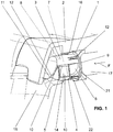
- FIG. 1 a perspective sectional view of a sanitary article 2, here in the form of a toilet bowl, and a rinse water distributor 1 is shown.
- the sanitary article 2 may also be a urinal.
- the rinsing water distributor 1 serves to distribute rinse water in the sanitary article 2.
- the sanitary article 2 comprises a wall 15, which leads to a siphon area, not shown here.
- the rinse water distributor 1 is inserted here into a receptacle 16 of the sanitary article 2.
- the rinse water distributor 1 is supplied with rinse water through a passage 17 on the sanitary article 2.
- the passage 17 is in fluid communication with a cistern or similar element.
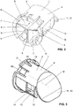
- FIG. 2 is a perspective rear view and in the FIG. 3 a front perspective view of the rinse water distributor 1 is shown.
- the rinsing water distributor 1 comprises an outer wall 3 extending around a central axis M.
- the outer wall 3 delimits a pipe section 4, through which the rinsing water is passed.
- the rinse water distributor 1 comprises a partition wall 5 arranged in the pipe section 4.
- the partition wall 5 separates the pipe section 4 into at least three distribution sections 6, 7, 8.
- the partition wall is T-shaped here.
- a left distribution section 6, a right distribution section 7 and an upper distribution section 8 are arranged.
- the left and the right distribution section 6, 7 run side by side and the upper distribution section 8 is, seen in the installation position, above the two distribution sections 6, 7. All three distribution sections 6, 7, 8 extend in the direction of the central axis M and parallel to each other.
- Each of the distribution sections 6, 7, 8 each comprises one inlet opening 9 and one outlet opening 10.
- rinsing water can be guided in a flow direction F from the inlet opening 9 to the outlet opening 10.
- the flow direction F extends at least at the beginning, ie near the inlet opening 9, substantially in the direction of the central axis M.
- the outlet opening 10 of the left connection section 6 is seen in the installed position and in the direction of flow F of the rinse water from the left side of the rinse water distributor 1 through the outer wall 3 from.
- the outlet opening 10 of the left distribution section 6 is designed for wetting a left region of the wall of the sanitary article 2.
- the outlet opening 10 of the right-hand distribution section 7 viewed in the installed position and the direction of flow F of the rinsing water, is laterally to the right of the rinsing water distributor 1 through the outer wall 3.
- the outlet opening 10 of the right distribution section 7 is designed for wetting a right region of the wall of the sanitary article 2.
- the wall of the sanitary article 2 is essentially wetted and cleaned with the rinsing water.
- the guided from these two outlet openings 10 water jet is preferably formed such that the wall of the sanitary article 2 is substantially completely wetted.
- the outlet opening 10 of the upper distribution section 8 is designed to flush out the siphon area of the sanitary article 2.
- a corresponding jet is guided through the outlet opening 10 in the direction of the siphon, wherein this beam relatively accurately targeted must hit the siphon, so that on the one hand the siphon area is well rinsed and so on the other hand, the emergence of splashes from the toilet bowl or the urinal, be avoided.
- the upper distribution section 8 is seen installed above the left and right distribution section 7, 6 arranged.
- the outlet openings 10 of the left and right distribution section 6, 7 are arranged in the flow direction F of the rinsing water in front of the outlet opening 10 of the upper distribution section 8. That is, the rinse water travels in the left and right distribution sections 6, 7 a smaller way back than in the upper distribution section 8.
- the rinse water from the outlet openings 10 of the left and right distribution section 6, 7 will flow through a shorter guide length, but this is much less critical due to the different function of the corresponding rinse water.
- FIG. 4b is a sectional view taken along the section BB of FIG. 4a shown.
- the guide length in the upper distribution section 8 is greater than the guide length in the left or in the right distribution section 6 or 7.
- the guide lengths are shown with the lines F6, 7 and F8.
- the outlet opening 10 of the upper distribution section 9 is arranged frontally to the pipe section 4. That is, the water flows from the front side of the pipe section, while the water flows from the left and right distribution section 6, 7 laterally to the pipe section 4.
- the rinsing water distributor 1 further comprises, as shown in the figures, a deflection surface 11.
- the deflection surface 11 is integrally formed on the rinse water distributor 1.
- the deflection surface 11 is used to deflect the rinse water of the upper distribution section 8 after the outlet opening 10.
- the rinse water from the upper distribution section 8 by the deflection 11 is correspondingly down in Direction of the siphon diverted.
- the deflection surface 11 extends at an angle inclined to the central axis M. In addition, it has a slight convexity, and this in the FIG. 4b is shown.
- the deflection surface 11 extends completely over the outlet opening 10 of the upper distribution section 8.
- the maximum extent of the deflection surface 11 is preferably such that it does not extend beyond a geometric enveloping circle H which forms the continuation of the tube section 4.
- the envelope H is in the FIG. 4b schematically drawn.
- at least the deflection surface 11 extends over the center axis M so that the deflection surface 11 likewise provides a corresponding guide length for the rinsing water from the upper distribution section 8.
- the deflection surface 11 closes here the front end of the pipe section 4.
- the outlet opening 10 from the upper distribution section 8 has an edge 13.
- the edge 13 forms a partial boundary of the outlet opening 10 and the rinse water flows over the edge 13 away.
- the edge 13 is thereby formed by the partition wall 5, which delimits the upper distribution section 8 with respect to the left and the right distribution section 6, 7.
- the edge 13 is located at a distance from the deflection surface 11. By this distance, a gap 18 is created. Due to the distance between the deflection surface 11 and the edge 13 of the cross section of the gap 18 can be varied, thereby also an optimization of Spülwasserstrahls from the outlet opening 10 of the upper distribution section 8 is made possible.
- the distribution sections 6, 7, 8 extend as far as possible from the inlet opening 9 as far as the outlet opening 10 in the direction of the central axis M.
- the upper distribution portion 8 is formed to be straight along the center axis M over a longer distance than the left and / or right distribution portions 6, 7.
- the upper distribution portion 8 be extended over a longer distance is designed to be rectilinear than the left / or the right distribution section 6, 7, because for the directed to the siphon rinse water jet, which is provided from the upper distribution section 8, a higher accuracy is required because it after leaving the Leitf kaue to hitting the Siphon water is no longer performed, whereas the both lateral rinsing water streams flow along after a short distance of the Weft wall.
- a guide surface 14 is arranged in the left and right distribution section 6, 7.
- the guide surface 14 is concavely curved here and redirects the distribution section 6, 7 to the respective outlet opening 10. As a result, the rinse water, which is guided in the left and in the right distribution section 6, 7, deflected accordingly.
- the partition wall 5 between the left and right distribution sections 6, 7 is located as in Figs Figures 2 and 4a is shown well in a vertical plane VE.
- the dividing wall, which delimits the left and right distribution sections 6, 7 from the upper distribution section 8, is shown substantially V-shaped here. That is, the partition wall 5 is located at two sections each inclined at an angle to the vertical plane VE.
- the partition can also lie in a horizontal plane.
- the left and right distribution sections 6, 7 are substantially symmetrical to each other with respect to the partition wall 5 and the vertical plane VE, respectively, lying between these two distribution sections 6, 7.
- the upper distribution section 8 is also formed substantially symmetrically with respect to the partition wall 5, or the vertical plane VE.
- the rinsing water distributor 1 further comprises latching elements 19 arranged in the region of the outer wall 3.
- the latching elements 19 are spring bars which make it possible for the flushing water distributor 1 to engage in the receptacle 16 on the sanitary article 2.
- the rinsing water distributor 1 comprises alignment elements 20.
- the alignment elements 20 serve to align the rinsing water distributor 1 in the receptacle 16 and are thereby provided by the outer wall 3 projecting webs.
- the rinse water distributor 1 in the embodiment shown further comprises a Stop edge 21, which cooperates with a stop 22 in the area of the receptacle 16 of the sanitary article 2, so that the rinse water distributor 1 can be pushed into abutment in the receptacle 16.
- LIST OF REFERENCE NUMBERS 1 Flushing water 17 passage 2 sanitary ware 18 gap 3 outer wall 19 locking element 4 pipe section 20 aligning 5 partition wall 21 stop edge 6 left distribution section 22 attack 7 right distribution section 23 baffle 8th upper distribution section 9 inlet opening M central axis 10 outlet opening H enveloping circle 11 deflection F flow direction 12 convex curvature VE vertical plane 13 edge HE WL 14 baffle 15 wall 16 admission
Abstract
Ein Spülwasserverteiler (1) für einen Sanitärartikel (2), wie eine Klosettschüssel oder ein Urinal, mit einer Wand (15) und einem Siphonbereich, umfassend eine sich um eine Mittelachse (M) herumerstreckende Aussenwand (3), welche einen Rohrabschnitt (4) begrenzt, und eine im Rohrabschnitt (4) angeordnete Trennwand (5), welche den Rohrabschnitt (4) in mindestens einen linken, einen rechten und einen oberen Verteilungsabschnitt (6, 7, 8) aufteilt, wobei jeder der Verteilungsabschnitte (6, 7, 8) eine Eintrittsöffnung (9) und eine Austrittsöffnung (10) umfasst, wobei in jedem der Verteilungsabschnitte (6, 7, 8) Spülwasser in einer Fliessrichtung (F) von der Eintrittsöffnung (9) zur Austrittsöffnung (10) fliesst, wobei die Austrittsöffnung (10) des linken Verteilungsabschnitts (6) in Einbaulage und in Fliessrichtung (F) des Spülwassers gesehen seitlich links vom Spülwasserverteiler (1) durch die Aussenwand (3) abgeht und zur Benetzung eines linken Bereichs der Wand des Sanitärartikels (2) ausgebildet ist, wobei die Austrittsöffnung (10) des rechten Verteilungsabschnitts (7) in Einbaulage und in Fliessrichtung (F) des Spülwassers gesehen seitlich rechts vom Spülwasserverteiler (1) durch die Aussenwand (3) abgeht und zur Benetzung eines rechten Bereichs der Wand des Sanitärartikels (2) ausgebildet ist, wobei die Austrittsöffnung (10) des oberen Verteilungsabschnitts (8) zur Ausspülung des Siphonbereichs ausgebildet ist, wobei der obere Verteilungsabschnitt (8) in Einbaulage gesehen oberhalb des linken und des rechten Verteilungsabschnitts (6, 7) angeordnet ist, und wobei die Austrittsöffnungen (10) des linken und rechten Verteilungsabschnittes (6, 7) in Fliessrichtung (F) des Spülwassers gesehen vor der Austrittsöffnung (10) des oberen Verteilungsabschnittes (8) liegen.A flushing water distributor (1) for a sanitary article (2), such as a lavatory bowl or urinal, comprising a wall (15) and a siphon area an outer wall (3) extending around a central axis (M) which delimits a pipe section (4), and a partition wall (5) arranged in the pipe section (4), which divides the pipe section (4) into at least one left, one right and one upper distribution section (6, 7, 8), each of the distribution sections (6, 7, 8) forming a Includes inlet opening (9) and an outlet opening (10), wherein flushing water flows in each of the distribution sections (6, 7, 8) in a flow direction (F) from the inlet opening (9) to the outlet opening (10), wherein the outlet opening (10) of the left distribution section (6) in the installation position and in the flow direction (F) of the rinsing water is seen laterally left of the rinse water distributor (1) through the outer wall (3) and for wetting a left portion of the wall of the sanitary article (2) is trained, wherein the outlet opening (10) of the right-hand distribution section (7) in installation position and in the direction of flow (F) of the rinsing water emerges laterally to the right of the rinsing water distributor (1) through the outer wall (3) and wetting a right-hand region of the wall of the sanitary article (2) is trained, wherein the outlet opening (10) of the upper distribution section (8) is designed to purge the siphon area, wherein the upper distribution section (8) is arranged in the installed position above the left and right distribution section (6, 7), and wherein the outlet openings (10) of the left and right distribution section (6, 7) in the flow direction (F) of the rinse water in front of the outlet opening (10) of the upper distribution section (8) lie.
Description
Die vorliegende Erfindung betrifft ein Spülwasserverteiler für einen Sanitärartikel nach dem Oberbegriff von Anspruch 1.The present invention relates to a flushing water distributor for a sanitary article according to the preamble of
Bei, insbesondere keramischen, Sanitärartikeln werden zur besseren Verteilung von Spülwasser im Sanitärartikel Spülwasserverteiler eingesetzt. Beispielsweise offenbart die
Aus der
Die aus dem Stand der Technik bekannten Spülwasserverteiler haben den Nachteil, dass das Spülwasser nicht optimal in die Klosettschüssel geleitet wird. Dies kann zu einem Überschiessen von Spülwasser aus der Klosettschüssel oder zu Spritzern aus der Klosettschüssel führen. Bei sogenannt randlosen Klosettschüsseln wird der Effekt besonders nachteilig.The Spülwasserverteiler known from the prior art have the disadvantage that the rinse water is not optimally directed into the toilet bowl. This can lead to an overshoot of rinse water from the toilet bowl or splashes from the toilet bowl. In so-called rimless toilet bowls, the effect is particularly disadvantageous.
Ausgehend von diesem Stand der Technik liegt der Erfindung eine Aufgabe zugrunde, ein Spülwasserverteiler anzugeben, welcher die Nachteile des Standes der Technik überwindet. Insbesondere soll der Spülwasserverteiler eine verbesserte, insbesondere eine kontrolliertere Verteilung, des Spülwassers ermöglichen. Eine besonders bevorzugte Aufgabe ist es, dass ein mittlerer auf den Siphonbereich auftreffender Wasserstrahl vom Spülwasserverteiler her genauer gerichtet werden kann.Based on this prior art, the invention has for its object to provide a Spülwasserverteiler, which overcomes the disadvantages of the prior art. In particular, the rinsing water distributor should enable an improved, in particular a more controlled distribution, of the rinsing water. A particularly preferred The task is that a mean water jet impinging on the siphon area can be directed more precisely from the rinse water distributor.
Diese Aufgabe löst der Gegenstand von Anspruch 1. Demgemäss umfasst ein Spülwasserverteiler für einen Sanitärartikel eine sich um eine Mittelachse herumerstreckende Aussenwand, welche einen Rohrabschnitt begrenzt, und eine im Rohrabschnitt angeordnete Trennwand, welche den Rohrabschnitt in mindestens einen linken, einen rechten und einen oberen Verteilungsabschnitt aufteilt, wobei jeder der Verteilungsabschnitte eine Eintrittsöffnung und eine Austrittsöffnung umfasst. In jedem der Verteilungsabschnitt fliesst Spülwasser in einer Fliessrichtung von der Eintrittsöffnung zur Austrittsöffnung. Die Austrittsöffnung des linken Verteilungsabschnitts geht in Einbaulage und in Fliessrichtung des Spülwassers gesehen seitlich links vom Spülwasserverteiler durch die Aussenwand vom Spülwasserverteiler ab. Die Austrittsöffnung ist dabei zur Benetzung eines linken Bereichs der Wand des Sanitärartikels ausgebildet. Die Austrittsöffnung des rechten Verteilungsabschnitts geht in Einbaulage und in Fliessrichtung des Spülwassers gesehen seitlich rechts vom Spülwasserverteiler durch die Aussenwand vom Spülwasserverteiler ab. Die Austrittsöffnung ist dabei zur Benetzung eines rechten Bereichs der Wand des Sanitärartikels ausgebildet. Die Austrittsöffnung des oberen Verteilungsabschnitts ist zur Ausspülung des Siphonbereichs ausgebildet. Der obere Verteilungsabschnitt ist in Einbaulage gesehen oberhalb des linken und des rechten Verteilungsabschnitts angeordnet. Die Austrittsöffnungen des linken und rechten Verteilungsabschnittes liegen in Fliessrichtung des Spülwassers gesehen vor der Austrittsöffnung des oberen Verteilungsabschnittes. Mit anderen Worten heisst dies, dass die Austrittsöffnung des oberen Verteilungsabschnittes in Richtung der Mittelachse gesehen weiter von den Eintrittsöffnungen weg liegt als die Austrittsöffnungen des linken und rechten Verteilungsabschnittes.Accordingly, a rinse water distributor for a sanitary article comprises an outer wall extending around a central axis, which delimits a pipe section, and a partition arranged in the pipe section, which divides the pipe section into at least one left, one right and one upper distribution section splits, wherein each of the distribution sections comprises an inlet opening and an outlet opening. In each of the distribution sections, rinse water flows in a flow direction from the inlet opening to the outlet opening. The outlet opening of the left distribution section is in installation position and in the direction of flow of the rinse water seen from the left side of the rinse water distributor through the outer wall of the rinse water distributor from. The outlet opening is designed for wetting a left portion of the wall of the sanitary article. In the installation position and in the direction of flow of the rinsing water, the outlet opening of the right-hand distribution section goes from the rinsing water distributor to the right side of the rinsing water distributor through the outer wall. The outlet opening is designed for wetting a right portion of the wall of the sanitary article. The outlet opening of the upper distribution section is designed to purge the siphon area. The upper distribution section is arranged in the installed position above the left and right distribution section. The outlet openings of the left and right distribution section lie in the direction of flow of the rinse water in front of the outlet opening of the upper distribution section. In other words, this means that the outlet opening of the upper distribution section seen in the direction of the central axis is further away from the inlet openings than the outlet openings of the left and right distribution section.
Durch diese Anordnung ergeht der Vorteil, dass der obere Verteilungsabschnitt länger als der rechte bzw. der linke Verteilungsabschnitt ausgebildet ist. Die Austrittsöffnung des oberen Verteilungsabschnittes liegt aufgrund der Anordnung des oberen Verteilungsabschnittes oberhalb der beiden anderen Verteilungsabschnitte weiter entfernt von der Eintrittsöffnung als die Austrittsöffnungen der beiden anderen Verteilungsabschnitte. Dies insbesondere bei gleicher Baugrösse. Hierdurch kann dem durchfliessenden Spülwasser eine längere Führung bereitgestellt werden, so dass die Strömung sich im oberen Verteilungsabschnitt beruhigt, wodurch der vom oberen Verteilungsabschnitt abgehende Spülwasserstrahl zielgerichteter in die Keramik geführt werden kann. Die Genauigkeit des in den Siphonbereich gerichteten Spülwasserstrahls ist für die Ausspülung des Siphons von grösster Wichtigkeit. Durch ein präzises Auftreffen des Spülwasserstrahls wird erreicht, dass keine Spritzer entstehen. Bei den die Wand des Sanitärartikels benetzenden Spülwasserstrahlen aus dem linken bzw. rechten Verteilungsabschnitt ist die Führung durch den Spülwasserverteiler weniger wichtig, weil hier das Wasser im Wesentlichen durch die Oberfläche des Sanitärartikels geführt wird.By this arrangement, there is an advantage that the upper distribution portion is formed longer than the right and left distribution portions. The outlet opening of the upper distribution section is due to the arrangement of the upper distribution section above the other two distribution sections further away from the inlet opening than the outlet openings of the other two Distribution sections. This especially for the same size. As a result, a longer guide can be provided to the flowing rinse water, so that the flow calms down in the upper distribution section, whereby the rinse water jet originating from the upper distribution section can be guided in a targeted manner into the ceramic. The accuracy of the flushing water jet directed into the siphon area is of the utmost importance for the flushing of the siphon. Precise impingement of the rinse water jet ensures that no splashes occur. In the rinse water jets wetting the wall of the sanitary article from the left or right distribution section, the guidance through the rinse water distributor is less important, because here the water is guided essentially through the surface of the sanitary article.
Mit anderen Worten kann die Funktionsweise wie folgt dargestellt werden: Der linke und der rechte Verteilungsabschnitt sind in Einbaulage auf die Wand des Sanitärartikels gerichtet und fliessen über die Wand in Richtung des Siphons des Sanitärartikels. Das durch diese beiden Verteilungsabschnitte bereitgestellte Wasser reinigt im Wesentlichen die Oberflächen des Sanitärartikels. Der obere Verteilungsabschnitt ist in Einbaulage wie bereits erwähnt auf den Siphonbereich des Sanitärartikels gerichtet und sorgt für eine Ausspülung des Siphonbereiches. Gerade bei diesem Strahl ist es wichtig, dass dieser möglichst zielgerichtet auf den entsprechenden Bereich gerichtet ist. Die Genauigkeit des Spülwasserstrahls aus dem oberen Verteilungsabschnitt kann durch die Anordnung oberhalb des linken und des rechten Verteilungsabschnitts stark verbessert werden.In other words, the operation can be represented as follows: The left and the right distribution portion are directed in the installed position on the wall of the sanitary article and flow over the wall in the direction of the siphon of the sanitary article. The water provided by these two distribution sections substantially cleans the surfaces of the sanitary article. The upper distribution section is directed in the installed position as already mentioned on the siphon area of the sanitary article and ensures a flushing of the siphon area. Especially with this beam, it is important that this is targeted as possible to the appropriate area. The accuracy of the rinse water jet from the upper distribution section can be greatly improved by the arrangement above the left and right distribution sections.
Vorzugsweise ist die Austrittsöffnung des oberen Verteilungsabschnittes oberhalb der Austrittsöffnungen des linken und rechten Verteilungsabschnittes angeordnet.Preferably, the outlet opening of the upper distribution section is arranged above the outlet openings of the left and right distribution section.
Der Gesamtvolumenstrom wird basierend auf den Querschnitten auf die drei Verteilungsabschnitte aufgeteilt. Vorzugsweise sind genau drei Verteilungsabschnitte angeordnet. Je nach Funktion und Verteilung des Spülwassers, wäre es aber auch denkbar mehr als drei Verteilungsabschnitte anzuordnen.The total volume flow is divided between the three distribution sections based on the cross sections. Preferably, exactly three distribution sections are arranged. Depending on the function and distribution of the rinse water, it would also be conceivable to arrange more than three distribution sections.
Vorzugsweise ist die Austrittsöffnung des oberen Verteilungsabschnitts stirnseitig zum Rohrabschnitt angeordnet. Unter einer stirnseitigen Anordnung wird verstanden, dass die Austrittsöffnung im Wesentlichen gegenüber von der Eintrittsöffnung angeordnet ist. Diese Anordnung hat den Vorteil, dass die Austrittsöffnung des oberen Verteilungsabschnitts bezüglich der Austrittsöffnung des rechten und linken Verteilungsabschnitts in Fliessrichtung gesehen weiter vorne angeordnet werden kann, wodurch die besagte verlängerte Führungslänge einfach umsetzbar ist.Preferably, the outlet opening of the upper distribution section is arranged frontally to the pipe section. Under an end-side arrangement is understood that the outlet opening is arranged substantially opposite to the inlet opening. These Arrangement has the advantage that the outlet opening of the upper distribution section with respect to the outlet opening of the right and left distribution section can be arranged seen in the direction of flow further forward, whereby said extended guide length is easily implemented.
Je nach Ausbildung liegt liegt der obere Verteilungsabschnitt in Einbaulage gesehen vorzugsweise ausschliesslich oberhalb der Mittelachse. Hierdurch wird erreicht, dass der zur Verfügung stehende Volumenstrom optimal auf die verschiedenen Verteilungsabschnitte aufgeteilt wird. Wird im oberen Verteilungsabschnitt ein grösserer Volumenstrom benötigt, so kann sich dieser auch unter die Mittelachse erstrecken.Depending on the design, the upper distribution section, viewed in the installation position, is preferably located exclusively above the central axis. This ensures that the available volume flow is optimally distributed to the various distribution sections. If a larger volume flow is needed in the upper distribution section, it may also extend below the central axis.
Vorzugsweise ist weiter eine Umlenkfläche zur Umlenkung des aus dem oberen Verteilungsabschnittes heraustretetenden Spülwasserstroms in Richtung des Siphonbereiches. Die Umlenkfläche lenkt das Spülwasser des oberen Verteilungsabschnittes nach der Austrittsöffnung nach unten hin um. Nach unten hin heisst in diesem Zusammenhang in Richtung der beiden anderen Verteilungsabschnitte bzw. im eingebauten Zustand in Richtung des Siphonbereichs des Sanitärartikels. In einer ersten Variante ist die Umlenkfläche am Spülwasserverteiler angeformt und in einer zweiten Variante ist die Umlenkfläche am Sanitärartikel angeformt.Preferably, a deflection surface is also provided for deflecting the flushing water flow emerging from the upper distribution section in the direction of the siphon area. The deflection deflects the rinse water of the upper distribution section to the outlet opening to the bottom. Downwards in this context means in the direction of the two other distribution sections or in the installed state in the direction of the siphon area of the sanitary article. In a first variant, the deflection surface is integrally formed on the rinse water distributor and in a second variant, the deflection surface is formed on the sanitary article.
In der ersten Variante ist, wie erwähnt, die Umlenkfläche am Spülwasserverteiler angeformt. Die am Spülwasserverteiler angeformte Umlenkfläche weist den Vorteil auf, dass vom oberen Verteilungsabschnitt kontrolliert nach dem Austritt aus der Austrittsöffnung an die gewünschte Stelle umgeleitet werden kann. Aufgrund der Integration in den Spülwasserverteiler kann die Umlenkung unabhängig vom Sanitärartikel erfolgen, was gerade bei keramischen Sanitärartikeln von Vorteil ist, weil dort mit grossen Fertigungstoleranzen zu rechnen ist.In the first variant, as mentioned, the deflection is formed on the rinse water manifold. The deflecting surface integrally formed on the flushing water distributor has the advantage that it can be diverted from the upper distributing section to the desired position in a controlled manner after it leaves the outlet opening. Due to the integration in the rinse water distributor, the deflection can be done independently of the sanitary article, which is particularly advantageous in ceramic sanitary ware, because there is expected to be large manufacturing tolerances.
Die Umlenkfläche schliesst sich vorzugsweise der Aussenwand an.The deflection surface preferably adjoins the outer wall.
Vorzugsweise erstreckt sich die Umlenkfläche beider Varianten quer auf die Mittelachse gesehen im Wesentlichen winklig geneigt zur Mittelachse. Hierdurch kann der aus dem oberen Verteilungsabschnitt austretende Wasserstrahl entsprechend umgelenkt werden. Vorzugsweise erstreckt sich die Umlenkfläche beider Varianten vollständig über die Austrittsöffnung des oberen Verteilungsabschnittes. Weiter erstreckt sich die Umlenkfläche bevorzugt maximal bis zu einem geometrischen Hüllkreis, der die Fortsetzung des Rohrabschnittes bildet, und minimal mindestens bis zur Mittelachse. Diese Anordnung der Umlenkfläche hat den Vorteil, dass dem Wasserstrahl aus dem oberen Verteilungsabschnitt eine möglichst lange Führung gegeben wird, was wiederum der Präzision des Wasserstrahls in den Sanitärartikel förderlich ist. Bei der Variante, gemäss welcher die Umlenkfläche durch den Sanitärartikel bereitgestellt wird, kann sich die Umlenkfläche auch weiter in Richtung des Siphonbereichs erstrecken.Preferably, the deflection of both variants extends transversely to the central axis seen substantially at an angle to the central axis. As a result, the water jet emerging from the upper distribution section can be correspondingly deflected. Preferably, the deflection of both variants extends completely over the outlet opening of the upper distribution section. Furthermore, the deflection surface preferably extends maximally to a geometric enveloping circle, which forms the continuation of the pipe section, and at least minimally to the central axis. This arrangement of the deflection surface has the advantage that the water jet from the upper distribution section as long as possible guidance is given, which in turn is the precision of the water jet in the sanitary article conducive. In the variant according to which the deflection surface is provided by the sanitary article, the deflection surface may also extend further in the direction of the siphon area.
Vorzugsweise ist die Umlenkfläche beider Varianten mindestens abschnittsweise mit einer konvexen Krümmung gekrümmt ausgebildet.Preferably, the deflection surface of both variants is curved at least in sections with a convex curvature.
Vorzugsweise ist der Abstand zwischen der Eintrittsöffnung in den oberen Verteilungsabschnitt und der Umlenkfläche grösser als der Abstand zwischen der Eintrittsöffnung in den linken bzw. rechten Verteilungsabschnitt und der Austrittsöffnung des linken bzw. rechten Verteilungsabschnitts. Das heisst wiederum, dass die Führungslänge in den Verteilungsabschnitt für den oberen Verteilungsabschnitt grösser ist als für den linken und den rechten Verteilungsabschnitt.Preferably, the distance between the inlet opening in the upper distribution section and the deflection surface is greater than the distance between the inlet opening in the left and right distribution section and the outlet opening of the left and right distribution section. This in turn means that the guide length in the distribution section for the upper distribution section is larger than for the left and right distribution sections.
Die Umlenkfläche schliesst sich vorzugsweise stirnseitig dem Rohrabschnitt an. Das heisst, die Umlenkfläche steht vom Rohrabschnitt ab.The deflection surface preferably adjoins the end of the pipe section. This means that the deflection surface is off the pipe section.
Vorzugsweis begrenzt die den oberen Verteilungsabschnitt gegenüber des linken und des rechten Verteilungsabschnitt abgrenzende Trennwand die Austrittsöffnung aus dem oberen Verteilungsabschnitt mit einer Kante, über welche das Spülwasser hinwegströmt.Preferably, the dividing wall delimiting the upper distribution section from the left and right distribution sections limits the discharge opening from the upper distribution section with an edge over which the flushing water flows.
Die besagte Kante liegt in einem Abstand zur Umlenkfläche, derart, dass der Wasserstrahl aus dem oberen Verteilungsabschnitt durch den aufgrund des Abstandes gebildeten Zwischenraums zwischen Umlenkfläche und Kante hindurchfliessen kann.Said edge is at a distance from the deflection surface, such that the water jet from the upper distribution section can flow through the gap formed between the deflection surface and the edge due to the distance.
Der Abstand zwischen Kante und Umlenkfläche kann derart gewählt werden, dass der Querschnitt, durch welchen das Wasser hindurch geführt wird, gleich, kleiner oder grösser zum Querschnitt des oberen Verteilungsabschnittes ist. Hierdurch kann die Geschwindigkeit des Wasserstrahls variiert werden.The distance between edge and deflection surface can be chosen such that the Cross-section through which the water is passed through, equal to, smaller or larger than the cross section of the upper distribution section. As a result, the speed of the water jet can be varied.
Vorzugsweise erstrecken sich die Verteilungsabschnitte von der Eintrittsöffnung gesehen möglichst weit bis zur Austrittsöffnung hin in Richtung der Mittelachse geradlinig. Durch die möglichst lange sich in Richtung der Mittelachse erstreckende Ausbildung ergeht der Vorteil, dass sich die Strömung des Spülwassers in den Verteilungsabschnitten beruhigen kann, bevor diese zur Austrittsöffnung geführt wird.Preferably, the distribution sections extend as far as possible from the inlet opening to the outlet opening in the direction of the central axis in a straight line. By the longest possible extending in the direction of the central axis training, there is the advantage that the flow of rinsing water in the distribution sections can calm down before it is guided to the outlet opening.
Besonders bevorzugt erstreckt sich der obere Verteilungsabschnitt über eine längere Distanz geradlinig, als der linke und/oder der rechte Verteilungsabschnitt. Hierdurch wird erreicht, dass die Strömung im oberen Verteilungsabschnitt über eine längere Strecke geführt wird, was vorteilhaft ist für deren strömungstechnische Beruhigung.Particularly preferably, the upper distribution section extends in a straight line over a longer distance than the left and / or the right distribution section. This ensures that the flow is guided in the upper distribution section over a longer distance, which is advantageous for the fluidic calming.
Vorzugsweise ist im linken und im rechten Verteilungsabschnitt je eine Leitfläche angeordnet, welche den Verteilungsabschnitt zur jeweiligen Austrittsöffnung umlenkt. Weiter bevorzugt ist im linken und im rechten Verteilungsabschnitt je eine Leitfläche angeordnet, welche im Bereich der jeweiligen Eintrittsöffnung angeordnet ist. Beide Leitflächen haben den technischen Vorteil, dass der Strömung im jeweiligen Verteilungsabschnitt eine gewisse Führung bereitgestellt wird.Preferably, a guide surface is arranged in the left and in the right distribution section, which deflects the distribution section to the respective outlet opening. More preferably, a guide surface is arranged in the left and in the right distribution section, which is arranged in the region of the respective inlet opening. Both guide surfaces have the technical advantage that the flow is provided in the respective distribution section some guidance.
Vorzugsweise sind die Leitflächen derart angeordnet, dass diejenige im Bereich der Eintrittsöffnung das Spülwasser auf diejenige im Bereich der Austrittsöffnung umlenkt.Preferably, the guide surfaces are arranged such that the one in the region of the inlet opening deflects the rinse water to that in the region of the outlet opening.
Vorzugsweise lenkt die Leitfläche der Austrittsöffnung die Strömung um einen Winkel von 30° bis 60° bezüglich der Mittelachse aus.Preferably, the guide surface of the outlet opening deflects the flow at an angle of 30 ° to 60 ° with respect to the central axis.
Vorzugsweise ist die Leitfläche konkav gerundet ausgebildet.Preferably, the guide surface is concave rounded.
Vorzugsweise liegt die Trennwand zwischen dem linken und dem rechten Verteilungsabschnitt in einer Vertikalebene. Die Vertikalebene liegt in Einbaulage in der Vertikalen. Der linke und der rechte Verteilungsabschnitt sind bezüglich der Trennwand vorzugsweise im Wesentlichen symmetrisch zueinander ausgebildet. Vorzugsweise ist auch der obere Verteilungsabschnitt bezüglich der Trennwand im Wesentlichen symmetrisch ausgebildet. Das heisst, die Teile des oberen Verteilungsabschnittes, welche links zur Vertikalebene liegen, sind im Wesentlichen symmetrisch zu den Teilen des oberen Verteilungsabschnittes, welche rechts zur Vertikalebene liegen.Preferably, the partition wall between the left and right distribution sections lies in a vertical plane. The vertical plane is in vertical position. The left and right distribution sections are with respect to the partition wall preferably formed substantially symmetrical to each other. Preferably, the upper distribution section is formed substantially symmetrically with respect to the partition wall. That is, the parts of the upper distribution section, which lie to the left of the vertical plane, are substantially symmetrical to the parts of the upper distribution section, which are right to the vertical plane.
In einer ersten bevorzugten Variante liegt die Trennwand zwischen dem oberen Verteilungsabschnitt und dem linken bzw. dem rechten Verteilungsabschnitt in einer Horizontalebene.In a first preferred variant, the dividing wall between the upper distribution section and the left or right distribution section lies in a horizontal plane.
In einer zweiten bevorzugten Variante liegt die Trennwand zwischen dem oberen Verteilungsabschnitt und dem linken bzw. dem rechten Verteilungsabschnitt winklig geneigt zur Trennwand zwischen dem linken und dem rechten Verteilungsabschnitt liegt. Das heisst, die Trennwand, welche den oberen Verteilungsabschnitt zum rechten und zum linken Verteilungsabschnitt abgrenzt, ist V-förmig ausgebildet.In a second preferred variant, the dividing wall between the upper distribution section and the left and right distribution sections is inclined at an angle to the dividing wall between the left and right distribution sections. That is, the partition wall which delimits the upper distribution section to the right and left distribution sections is V-shaped.
Vorzugsweise liegen die Eintrittsöffnungen in einer gemeinsamen Ebene.Preferably, the inlet openings lie in a common plane.
Vorzugsweise ist der Querschnitt des linken und des rechten Verteilungsabschnittes gleich gross. Der Querschnitt des oberen Verteilungsabschnittes ist gleich, kleiner oder grösser als der Querschnitt des linken und/oder des rechten Verteilungsabschnittes.Preferably, the cross section of the left and the right distribution portion is the same size. The cross section of the upper distribution section is equal to, smaller or larger than the cross section of the left and / or the right distribution section.
Eine Sanitärartikel, insbesondere eine Klosettschüssel oder ein Urinal, umfassend eine Aufnahme für einen Spülwasserverteiler nach obiger Beschreibung sowie eine Wand und einen Siphonbereich, wobei der Spülwasserverteiler derart in die Aufnahme einsetzbar ist, dass der obere Verteilungsabschnitt oberhalb des linken und des rechten Verteilungsabschnitt liegt.A sanitary article, in particular a lavatory bowl or a urinal, comprising a receptacle for a flushing water distributor as described above and a wall and a siphon area, wherein the flushing water distributor is insertable into the receptacle such that the upper distribution section lies above the left and the right distribution section.
Weitere Ausführungsformen sind in den abhängigen Ansprüchen angegeben.Further embodiments are given in the dependent claims.
Bevorzugte Ausführungsformen der Erfindung werden im Folgenden anhand derPreferred embodiments of the invention are described below with reference to FIG
Zeichnungen beschrieben, die lediglich zur Erläuterung dienen und nicht einschränkend auszulegen sind. In den Zeichnungen zeigen:
- Fig. 1
- eine perspektivische Ansicht eines Spülwasserverteilers in einem Sanitärartikel, der teilweise geschnitten dargestellt ist;
- Fig. 2
- eine perspektivische Ansicht des Spülwasserverteilers nach
Figur 1 von hinten; - Fig. 3
- eine perspektivische Ansicht des Spülwasserverteilers nach
Figur 1 von vorne; - Fig. 4a
- eine Rückansicht des Spülwasserverteilers nach
Figur 1 ; - Fig. 4b
- eine Schnittansicht entlang der Schnittlinie B-B der
Figur 4a ; und - Fig. 4c
- eine Schnittansicht entlang der Schnittlinie C-C der
Figur 4c .
- Fig. 1
- a perspective view of a Spülwasserverteilers in a sanitary article, which is shown partially in section;
- Fig. 2
- a perspective view of the Spülwasserverteilers after
FIG. 1 from the back; - Fig. 3
- a perspective view of the Spülwasserverteilers after
FIG. 1 from the front; - Fig. 4a
- a rear view of the Spülwasserverteilers after
FIG. 1 ; - Fig. 4b
- a sectional view taken along the section BB of
FIG. 4a ; and - Fig. 4c
- a sectional view taken along the section line CC of
Figure 4c ,
In der
Der Spülwasserverteiler 1 ist hier in eine Aufnahme 16 des Sanitärartikels 2 eingesetzt. Dabei wird der Spülwasserverteiler 1 durch ein Durchgang 17 am Sanitärartikel 2 mit Spülwasser versorgt. Der Durchgang 17 steht dabei mit einem Spülkasten oder einem ähnlichen Element fluidisch in Verbindung.The rinse
In der
Der Spülwasserverteiler 1 umfasst eine sich um eine Mittelachse M herumerstreckende Aussenwand 3. Die Aussenwand 3 begrenzt dabei einen Rohrabschnitt 4, durch welchen das Spülwasser geführt wird. Weiter umfasst der Spülwasserverteiler 1 eine im Rohrabschnitt 4 angeordnete Trennwand 5. Die Trennwand 5 trennt den Rohrabschnitt 4 in mindestens drei Verteilungsabschnitte 6, 7, 8 auf. Im Wesentlichen ist die Trennwand hier T-förmig ausgebildet. In der gezeigten Ausführungsform ist ein linker Verteilungsabschnitt 6, ein rechter Verteilungsabschnitt 7 und ein oberer Verteilungsabschnitt 8 angeordnet. Der linke und der rechte Verteilungsabschnitt 6, 7 verlaufen nebeneinander und der obere Verteilungsabschnitt 8 liegt, in Einbaulage gesehen, oberhalb der beiden Verteilungsabschnitte 6, 7. Alle drei Verteilungsabschnitte 6, 7, 8 verlaufen in Richtung der Mittelachse M und parallel zueinander.The rinsing
Jeder der Verteilungsabschnitte 6, 7, 8 umfasst jeweils je eine Eintrittsöffnung 9 und je eine Austrittsöffnung 10. In jedem der Verteilungsabschnitt 6, 7, 8 ist Spülwasser in einer Fliessrichtung F von der Eintrittsöffnung 9 zur Austrittsöffnung 10 führbar. Die Fliessrichtung F erstreckt sich mindestens zu Beginn, also nahe der Eintrittsöffnung 9, im Wesentlichen in Richtung der Mittelachse M.Each of the
Die Austrittsöffnung 10 des linken Verbindungsabschnittes 6 geht in Einbaulage und in Fliessrichtung F des Spülwassers gesehen seitlich links vom Spülwasserverteiler 1 durch die Aussenwand 3 ab. Die Austrittsöffnung 10 des linken Verteilungsabschnittes 6 ist zur Benetzung eines linken Bereichs der Wand des Sanitärartikels 2 ausgebildet.The
Die Austrittsöffnung 10 des rechten Verteilungsabschnittes 7 geht in Einbaulage und Fliessrichtung F des Spülwassers gesehen seitlich rechts vom Spülwasserverteiler 1 durch die Aussenwand 3 ab. Die Austrittsöffnung 10 des rechten Verteilungsabschnittes 7 ist zur Benetzung eines rechten Bereichs der Wand des Sanitärartikels 2 ausgebildet.The
Über diese beiden Austrittsöffnungen des linken bzw. des rechten Verteilungsabschnittes 6, 7 wird also im Wesentlichen die Wand des Sanitärartikels 2 mit dem Spülwasser benetzt und gereinigt. Der aus diesen beiden Austrittsöffnungen 10 geführte Wasserstrahl ist vorzugsweise derart ausgebildet, dass die Wand des Sanitärartikels 2 im Wesentlichen vollständig benetzt wird.By means of these two outlet openings of the left or
Die Austrittsöffnung 10 des oberen Verteilungsabschnittes 8 ist zur Ausspülung des Siphonbereichs des Sanitärartikels 2 ausgebildet. Hierbei wird ein entsprechender Strahl durch die Austrittsöffnung 10 in Richtung des Siphonbereichs geführt, wobei dieser Strahl relativ zielgenau auf den Siphonbereich auftreffen muss, so dass einerseits der Siphonbereich gut gespült wird und so dass andererseits die Entstehung von Spritzern die aus der Klosettschüssel bzw. dem Urinal ausspritzen, vermieden werden.The
Der obere Verteilungsabschnitt 8 ist Einbaulage gesehen oberhalb des linken und des rechten Verteilungsabschnittes 7, 6 angeordnet. Weiter sind die Austrittsöffnungen 10 des linken und des rechten Verteilungsabschnittes 6, 7 in Fliessrichtung F des Spülwassers gesehen vor der Austrittsöffnung 10 des oberen Verteilungsabschnittes 8 angeordnet. Das heisst, das Spülwasser legt in den linken und rechten Verteilungsabschnitten 6, 7 einen kleineren Weg zurück als im oberen Verteilungsabschnitt 8. Dies hat den Vorteil, dass die Strömung im oberen Verteilungsabschnitt 8 weiter beruhigt werden kann, was für die Zielgenauigkeit des Spülstrahls, der aus der Austrittsöffnung 10 des oberen Verteilungsabschnittes 8 austritt, von grosser Wichtigkeit ist. Andererseits wird das Spülwasser aus den Austrittsöffnungen 10 des linken und rechten Verteilungsabschnittes 6, 7 eine kürzere Führungslänge durchfliessen, was aber aufgrund der unterschiedlichen Funktion des entsprechenden Spülwassers weit weniger kritisch ist.The
In der
Die Austrittsöffnung 10 des oberen Verteilungsabschnittes 9 ist stirnseitig zum Rohrabschnitt 4 angeordnet. Das heisst, das Wasser fliesst stirnseitig aus dem Rohrabschnitt aus, während das Wasser vom linken und rechten Verteilungsabschnitt 6, 7 seitlich zum Rohrabschnitt 4 abfliesst.The
Der Spülwasserverteiler 1 umfasst, wie in den Figuren gezeigt, weiterhin eine Umlenkfläche 11. Die Umlenkfläche 11 ist dabei am Spülwasserverteiler 1 einstückig angeformt. Die Umlenkfläche 11 dient der Umlenkung des Spülwassers des oberen Verteilungsabschnittes 8 nach der Austrittsöffnung 10. Dabei wird das Spülwasser vom oberen Verteilungsabschnitt 8 durch die Umlenkfläche 11 entsprechend nach unten in Richtung des Siphonbereichs umgelenkt. In der gezeigten Ausführungsform erstreckt sich die Umlenkfläche 11 winklig geneigt zur Mittelachse M. Darüber hinaus hat sie eine leichte Konvexität, sowie dies in der
Die Umlenkfläche 11 erstreckt sich hier vollständig über die Austrittsöffnung 10 des oberen Verteilungsabschnittes 8. Die maximale Ausdehnung der Umlenkfläche 11 ist vorzugsweise derart, dass sie sich nicht über einen geometrischen Hüllkreis H, der die Fortsetzung des Rohrabschnittes 4 bildet, hinauserstreckt. Der Hüllkreis H ist in der
Die Umlenkfläche 11 schliesst sich hier stirnseitig dem Rohrabschnitt 4 an. Die Austrittsöffnung 10 aus dem oberen Verteilungsabschnitt 8 weist eine Kante 13 auf. Die Kante 13 bildet dabei eine Teilbegrenzung der Austrittsöffnung 10 und das Spülwasser fliesst über die Kante 13 weg. Die Kante 13 wird dabei durch die Trennwand 5 gebildet, welche den oberen Verteilungsabschnitt 8 gegenüber dem linken und dem rechten Verteilungsabschnitt 6, 7 abgrenzt. Die Kante 13 liegt in einem Abstand zur Umlenkfläche 11. Durch diesen Abstand wird ein Zwischenraum 18 geschaffen. Durch den Abstand zwischen der Umlenkfläche 11 und der Kante 13 kann der Querschnitt des Zwischenraums 18 variiert werden, wobei hierdurch ebenfalls eine Optimierung des Spülwasserstrahls aus der Austrittsöffnung 10 des oberen Verteilungsabschnittes 8 ermöglicht wird.The
Von den Figuren ist deutlich, dass die Verteilungsabschnitte 6, 7, 8 sich von der Eintrittsöffnung 9 gesehen möglichst weit bis zur Austrittsöffnung 10 hin in Richtung der Mittelachse M geradlinig erstrecken. Dabei ist in der gezeigten Ausführungsform der obere Verteilungsabschnitt 8 über eine längere Distanz geradlinig entlang der Mittelachse M ausgebildet als der linke und/oder der rechte Verteilungsabschnitt 6, 7. Wie bereits erwähnt, ist es vorteilhaft, wenn der obere Verteilungsabschnitt 8 über eine längere Distanz geradlinig ausgebildet ist als der linke/oder der rechte Verteilungsabschnitt 6, 7, weil für den auf den Siphon gerichtete Spülwasserstrahl, der aus dem oberen Verteilungsabschnitt 8 bereitgestellt wird, eine höhere Genauigkeit erforderlich ist, da er nach Verlassen der Leitfäche bis zum Auftreffen auf das Siphonwasser nicht mehr geführt wird, wogegen die beiden seitlichen Spülwasserstrahle nach kurzer Distanz der Schusselwand entlang strömen.From the figures it is clear that the
Im linken und im rechten Verteilungsabschnitt 6, 7 ist, wie in der
Die Trennwand 5 zwischen dem linken und dem rechten Verteilungsabschnitt 6, 7 liegt, wie in den
Der linke und der rechte Verteilungsabschnitt 6, 7, sind bezüglich der Trennwand 5 bzw. der Vertikalebene VE, die zwischen diesen beiden Verteilungsabschnitten 6, 7 liegt, im Wesentlichen symmetrisch zueinander ausgebildet. Der obere Verteilungsabschnitt 8 ist bezüglich der Trennwand 5, bzw. der Vertikalebene VE im Wesentlichen ebenfalls symmetrisch ausgebildet.The left and
In der gezeigten Ausführungsform umfasst der Spülwasserverteiler 1 weiterhin im Bereich der Aussenwand 3 angeordnete Rastelemente 19. Bei den Rastelementen 19 handelt es sich hier um Federstege, welche ein Einrasten des Spülwasserverteiler 1 in der Aufnahme 16 am Sanitärartikel 2 ermöglichen.In the embodiment shown, the rinsing
Des Weiteren umfasst der Spülwasserverteiler 1 Ausrichtelemente 20. Die Ausrichtelemente 20 dienen dabei der Ausrichtung des Spülwasserverteiler 1 in der Aufnahme 16 und werden hierdurch von der Aussenwand 3 abstehende Stege bereitgestellt.Furthermore, the rinsing
Zudem umfasst der Spülwasserverteiler 1 in der gezeigten Ausführungsform weiter einen Anschlagsrand 21, welcher mit einem Anschlag 22 im Bereich der Aufnahme 16 des Sanitärartikels 2 zusammenarbeitet, sodass der Spülwasserverteiler 1 auf Anschlag in die Aufnahme 16 eingeschoben werden kann.
Claims (15)
eine sich um eine Mittelachse (M) herumerstreckende Aussenwand (3), welche einen Rohrabschnitt (4) begrenzt, und
eine im Rohrabschnitt (4) angeordnete Trennwand (5), welche den Rohrabschnitt (4) in mindestens einen linken, einen rechten und einen oberen Verteilungsabschnitt (6, 7, 8) aufteilt, wobei jeder der Verteilungsabschnitte (6, 7, 8) eine Eintrittsöffnung (9) und eine Austrittsöffnung (10) umfasst,
wobei in jedem der Verteilungsabschnitte (6, 7, 8) Spülwasser in einer Fliessrichtung (F) von der Eintrittsöffnung (9) zur Austrittsöffnung (10) fliesst,
wobei die Austrittsöffnung (10) des linken Verteilungsabschnitts (6) in Einbaulage und in Fliessrichtung (F) des Spülwassers gesehen seitlich links vom Spülwasserverteiler (1) durch die Aussenwand (3) abgeht und zur Benetzung eines linken Bereichs der Wand des Sanitärartikels (2) ausgebildet ist,
wobei die Austrittsöffnung (10) des rechten Verteilungsabschnitts (7) in Einbaulage und in Fliessrichtung (F) des Spülwassers gesehen seitlich rechts vom Spülwasserverteiler (1) durch die Aussenwand (3) abgeht und zur Benetzung eines rechten Bereichs der Wand des Sanitärartikels (2) ausgebildet ist,
wobei die Austrittsöffnung (10) des oberen Verteilungsabschnitts (8) zur Ausspülung des Siphonbereichs ausgebildet ist,
wobei der obere Verteilungsabschnitt (8) in Einbaulage gesehen oberhalb des linken und des rechten Verteilungsabschnitts (6, 7) angeordnet ist, und
wobei die Austrittsöffnungen (10) des linken und rechten Verteilungsabschnittes (6, 7) in Fliessrichtung (F) des Spülwassers gesehen vor der Austrittsöffnung (10) des oberen Verteilungsabschnittes (8) liegen.A flushing water distributor (1) for a sanitary article (2), such as a lavatory bowl or urinal, comprising a wall (15) and a siphon area
an outer wall (3) extending around a central axis (M) which delimits a pipe section (4), and
a partition wall (5) arranged in the pipe section (4), which divides the pipe section (4) into at least one left, one right and one upper distribution section (6, 7, 8), each of the distribution sections (6, 7, 8) forming a Includes inlet opening (9) and an outlet opening (10),
wherein flushing water flows in each of the distribution sections (6, 7, 8) in a flow direction (F) from the inlet opening (9) to the outlet opening (10),
wherein the outlet opening (10) of the left distribution section (6) in the installation position and in the flow direction (F) of the rinsing water is seen laterally left of the rinse water distributor (1) through the outer wall (3) and for wetting a left portion of the wall of the sanitary article (2) is trained,
wherein the outlet opening (10) of the right-hand distribution section (7) in installation position and in the direction of flow (F) of the rinsing water emerges laterally to the right of the rinsing water distributor (1) through the outer wall (3) and wetting a right-hand region of the wall of the sanitary article (2) is trained,
wherein the outlet opening (10) of the upper distribution section (8) is designed to purge the siphon area,
wherein the upper distribution section (8) is arranged in the installed position above the left and right distribution section (6, 7), and
wherein the outlet openings (10) of the left and right distribution section (6, 7) in the flow direction (F) of the rinse water in front of the outlet opening (10) of the upper distribution section (8) lie.
dass sich die Umlenkfläche (11) quer zur Mittelachse (M) gesehen im Wesentlichen winklig geneigt zur Mittelachse (M) erstreckt; und/oder
dass sich die Umlenkfläche (11) vollständig über die Austrittsöffnung (10) des oberen Verteilungsabschnitts (8) erstreckt und sich bevorzugt maximal bis zu einem geometrischen Hüllkreis (H), der die Fortsetzung des Rohrabschnittes (4) bildet, und minimal bis zur Mittelachse (M) erstreckt; und/oder
dass die Umlenkfläche (11) mindestens abschnittsweise mit einer konvexen Krümmung (12) gekrümmt ausgebildet ist; und/oder
dass der Abstand zwischen der Eintrittsöffnung (9) in den oberen Verteilungsabschnitt (8) und der Umlenkfläche (11) grösser ist als der Abstand zwischen der Eintrittsöffnung (9) in den linken bzw. rechten Verteilungsabschnitt (6, 7) und der Austrittsöffnung des linken bzw. rechten Verteilungsabschnitts (6, 7); und/oder
dass sich die Umlenkfläche (11) stirnseitig dem Rohrabschnitt (4) anschliesst.Flushing water distributor (1) according to claim 4, characterized in that
seen that the deflection surface (11) transverse to the central axis (M) substantially angularly inclined to the central axis (M) extends; and or
in that the deflecting surface (11) extends completely over the outlet opening (10) of the upper distribution section (8) and preferably maximally up to a geometrical enveloping circle (H) which forms the continuation of the pipe section (4) and minimal to the central axis ( M) extends; and or
that the deflection surface (11) is curved at least in sections with a convex curvature (12); and or
in that the distance between the inlet opening (9) in the upper distribution section (8) and the deflection surface (11) is greater than the distance between the inlet opening (9) in the left and right distribution section (6, 7) and the outlet opening of the left or right distribution section (6, 7); and or
that the deflection surface (11) adjoins the end of the pipe section (4).
wobei der linke und der rechte Verteilungsabschnitt (6, 7) bezüglich der Trennwand (5) bzw. der Vertikalebene (VE) im Wesentlichen symmetrisch zueinander ausgebildet sind und/oder
wobei der obere Verteilungsabschnitt (8) bezüglich der Trennwand (5) bzw. der Vertikalebene (VE) im Wesentlichen symmetrisch ausgebildet sind.Flushing water distributor (1) according to one of the preceding claims, characterized in that the dividing wall (5) lies between the left and the right distribution section (6, 7) in a vertical plane (VE),
wherein the left and the right distribution portion (6, 7) with respect to the partition wall (5) and the vertical plane (VE) are formed substantially symmetrical to each other and / or
wherein the upper distribution portion (8) with respect to the partition wall (5) and the vertical plane (VE) are formed substantially symmetrically.
Priority Applications (2)
| Application Number | Priority Date | Filing Date | Title |
|---|---|---|---|
| DK17190549.0T DK3453805T3 (en) | 2017-09-12 | 2017-09-12 | Flushing water distributor |
| EP17190549.0A EP3453805B1 (en) | 2017-09-12 | 2017-09-12 | Flush water distributor |
Applications Claiming Priority (1)
| Application Number | Priority Date | Filing Date | Title |
|---|---|---|---|
| EP17190549.0A EP3453805B1 (en) | 2017-09-12 | 2017-09-12 | Flush water distributor |
Publications (2)
| Publication Number | Publication Date |
|---|---|
| EP3453805A1 true EP3453805A1 (en) | 2019-03-13 |
| EP3453805B1 EP3453805B1 (en) | 2020-04-29 |
Family
ID=59856439
Family Applications (1)
| Application Number | Title | Priority Date | Filing Date |
|---|---|---|---|
| EP17190549.0A Active EP3453805B1 (en) | 2017-09-12 | 2017-09-12 | Flush water distributor |
Country Status (2)
| Country | Link |
|---|---|
| EP (1) | EP3453805B1 (en) |
| DK (1) | DK3453805T3 (en) |
Cited By (3)
| Publication number | Priority date | Publication date | Assignee | Title |
|---|---|---|---|---|
| EP3825480A1 (en) | 2019-11-21 | 2021-05-26 | Geberit International AG | Flush water distributor |
| EP3825481A1 (en) | 2019-11-21 | 2021-05-26 | Geberit International AG | Flush water distributor |
| FR3104622A1 (en) | 2019-12-17 | 2021-06-18 | Delabie | Rinsing system for toilet bowl and toilet bowl assembly - rinsing system |
Citations (3)
| Publication number | Priority date | Publication date | Assignee | Title |
|---|---|---|---|---|
| DE3315926A1 (en) | 1982-05-10 | 1983-12-08 | VEB Kombinat Technische Gebäudeausrüstung, DDR 7730 Leipzig | Water distributor for WCs |
| EP2602391A1 (en) * | 2011-12-05 | 2013-06-12 | KERAMAG Keramische Werke Aktiengesellschaft | Toilet bowl |
| WO2016184950A1 (en) | 2015-05-20 | 2016-11-24 | Cersanit Trade Mark Sp. Z O.O. | Insert for water distribution in a toilet bowl |
-
2017
- 2017-09-12 EP EP17190549.0A patent/EP3453805B1/en active Active
- 2017-09-12 DK DK17190549.0T patent/DK3453805T3/en active
Patent Citations (3)
| Publication number | Priority date | Publication date | Assignee | Title |
|---|---|---|---|---|
| DE3315926A1 (en) | 1982-05-10 | 1983-12-08 | VEB Kombinat Technische Gebäudeausrüstung, DDR 7730 Leipzig | Water distributor for WCs |
| EP2602391A1 (en) * | 2011-12-05 | 2013-06-12 | KERAMAG Keramische Werke Aktiengesellschaft | Toilet bowl |
| WO2016184950A1 (en) | 2015-05-20 | 2016-11-24 | Cersanit Trade Mark Sp. Z O.O. | Insert for water distribution in a toilet bowl |
Cited By (4)
| Publication number | Priority date | Publication date | Assignee | Title |
|---|---|---|---|---|
| EP3825480A1 (en) | 2019-11-21 | 2021-05-26 | Geberit International AG | Flush water distributor |
| EP3825481A1 (en) | 2019-11-21 | 2021-05-26 | Geberit International AG | Flush water distributor |
| FR3104622A1 (en) | 2019-12-17 | 2021-06-18 | Delabie | Rinsing system for toilet bowl and toilet bowl assembly - rinsing system |
| EP3839161A1 (en) | 2019-12-17 | 2021-06-23 | Delabie | Flushing system for toilet bowl, and toilet bowl and flushing system assembly |
Also Published As
| Publication number | Publication date |
|---|---|
| EP3453805B1 (en) | 2020-04-29 |
| DK3453805T3 (en) | 2020-07-20 |
Similar Documents
| Publication | Publication Date | Title |
|---|---|---|
| EP2969234B1 (en) | Atomizer nozzle for a sanitary water outlet and sanitary outlet fitting with a water outlet | |
| EP1743555B1 (en) | Outlet of a distributor of an espressomachine | |
| EP3453805B1 (en) | Flush water distributor | |
| DE202006009786U1 (en) | milk frother | |
| EP3486384B1 (en) | Flush toilet | |
| WO2015185460A1 (en) | Deflecting bend | |
| DE60204806T2 (en) | Blasting device for a mixed flow of gas and liquid | |
| CH716366B1 (en) | Flush water distributor for a sanitary article. | |
| EP2829666B1 (en) | Inlet fitting for a cistern | |
| DE60217792T2 (en) | jet | |
| EP0643177B1 (en) | Urinal | |
| EP3542906B1 (en) | Field sprayer with nozzle assemblies | |
| EP3825480A1 (en) | Flush water distributor | |
| EP2893981B1 (en) | Sludge separator | |
| EP3825479A1 (en) | Flush water distributor | |
| EP3719225B1 (en) | Device for dispensing cleaning agent | |
| EP3647504B1 (en) | Sanitary item arrangement | |
| DE102007010473B4 (en) | Sanitary shower mixer | |
| DE102018104689A1 (en) | Nozzle arrangement for a field sprayer | |
| EP3719226B1 (en) | Flush valve | |
| WO2011095250A1 (en) | Valve for regulating a fluid flow | |
| DE102016123791B3 (en) | Carburettor for an internal combustion engine of a working device | |
| EP4283057A1 (en) | Flush water distributor | |
| EP3848519A1 (en) | Sanitary device comprising a urinal and a suction siphon to be attached or connected to the urinal and a flushing nozzle | |
| EP3825481A1 (en) | Flush water distributor |
Legal Events
| Date | Code | Title | Description |
|---|---|---|---|
| PUAI | Public reference made under article 153(3) epc to a published international application that has entered the european phase |
Free format text: ORIGINAL CODE: 0009012 |
|
| STAA | Information on the status of an ep patent application or granted ep patent |
Free format text: STATUS: THE APPLICATION HAS BEEN PUBLISHED |
|
| AK | Designated contracting states |
Kind code of ref document: A1 Designated state(s): AL AT BE BG CH CY CZ DE DK EE ES FI FR GB GR HR HU IE IS IT LI LT LU LV MC MK MT NL NO PL PT RO RS SE SI SK SM TR |
|
| AX | Request for extension of the european patent |
Extension state: BA ME |
|
| STAA | Information on the status of an ep patent application or granted ep patent |
Free format text: STATUS: REQUEST FOR EXAMINATION WAS MADE |
|
| 17P | Request for examination filed |
Effective date: 20190418 |
|
| RBV | Designated contracting states (corrected) |
Designated state(s): AL AT BE BG CH CY CZ DE DK EE ES FI FR GB GR HR HU IE IS IT LI LT LU LV MC MK MT NL NO PL PT RO RS SE SI SK SM TR |
|
| GRAP | Despatch of communication of intention to grant a patent |
Free format text: ORIGINAL CODE: EPIDOSNIGR1 |
|
| STAA | Information on the status of an ep patent application or granted ep patent |
Free format text: STATUS: GRANT OF PATENT IS INTENDED |
|
| INTG | Intention to grant announced |
Effective date: 20191202 |
|
| GRAS | Grant fee paid |
Free format text: ORIGINAL CODE: EPIDOSNIGR3 |
|
| GRAA | (expected) grant |
Free format text: ORIGINAL CODE: 0009210 |
|
| STAA | Information on the status of an ep patent application or granted ep patent |
Free format text: STATUS: THE PATENT HAS BEEN GRANTED |
|
| AK | Designated contracting states |
Kind code of ref document: B1 Designated state(s): AL AT BE BG CH CY CZ DE DK EE ES FI FR GB GR HR HU IE IS IT LI LT LU LV MC MK MT NL NO PL PT RO RS SE SI SK SM TR |
|
| REG | Reference to a national code |
Ref country code: GB Ref legal event code: FG4D Free format text: NOT ENGLISH |
|
| REG | Reference to a national code |
Ref country code: CH Ref legal event code: EP |
|
| REG | Reference to a national code |
Ref country code: DE Ref legal event code: R096 Ref document number: 502017004954 Country of ref document: DE |
|
| REG | Reference to a national code |
Ref country code: AT Ref legal event code: REF Ref document number: 1263487 Country of ref document: AT Kind code of ref document: T Effective date: 20200515 |
|
| REG | Reference to a national code |
Ref country code: IE Ref legal event code: FG4D Free format text: LANGUAGE OF EP DOCUMENT: GERMAN |
|
| REG | Reference to a national code |
Ref country code: CH Ref legal event code: NV Representative=s name: ISLER AND PEDRAZZINI AG, CH |
|
| REG | Reference to a national code |
Ref country code: DK Ref legal event code: T3 Effective date: 20200713 |
|
| REG | Reference to a national code |
Ref country code: FI Ref legal event code: FGE |
|
| REG | Reference to a national code |
Ref country code: SE Ref legal event code: TRGR |
|
| REG | Reference to a national code |
Ref country code: NO Ref legal event code: T2 Effective date: 20200429 |
|
| REG | Reference to a national code |
Ref country code: NL Ref legal event code: MP Effective date: 20200429 |
|
| REG | Reference to a national code |
Ref country code: LT Ref legal event code: MG4D |
|
| PG25 | Lapsed in a contracting state [announced via postgrant information from national office to epo] |
Ref country code: GR Free format text: LAPSE BECAUSE OF FAILURE TO SUBMIT A TRANSLATION OF THE DESCRIPTION OR TO PAY THE FEE WITHIN THE PRESCRIBED TIME-LIMIT Effective date: 20200730 Ref country code: PT Free format text: LAPSE BECAUSE OF FAILURE TO SUBMIT A TRANSLATION OF THE DESCRIPTION OR TO PAY THE FEE WITHIN THE PRESCRIBED TIME-LIMIT Effective date: 20200831 Ref country code: LT Free format text: LAPSE BECAUSE OF FAILURE TO SUBMIT A TRANSLATION OF THE DESCRIPTION OR TO PAY THE FEE WITHIN THE PRESCRIBED TIME-LIMIT Effective date: 20200429 Ref country code: IS Free format text: LAPSE BECAUSE OF FAILURE TO SUBMIT A TRANSLATION OF THE DESCRIPTION OR TO PAY THE FEE WITHIN THE PRESCRIBED TIME-LIMIT Effective date: 20200829 |
|
| PG25 | Lapsed in a contracting state [announced via postgrant information from national office to epo] |
Ref country code: BG Free format text: LAPSE BECAUSE OF FAILURE TO SUBMIT A TRANSLATION OF THE DESCRIPTION OR TO PAY THE FEE WITHIN THE PRESCRIBED TIME-LIMIT Effective date: 20200729 Ref country code: RS Free format text: LAPSE BECAUSE OF FAILURE TO SUBMIT A TRANSLATION OF THE DESCRIPTION OR TO PAY THE FEE WITHIN THE PRESCRIBED TIME-LIMIT Effective date: 20200429 Ref country code: LV Free format text: LAPSE BECAUSE OF FAILURE TO SUBMIT A TRANSLATION OF THE DESCRIPTION OR TO PAY THE FEE WITHIN THE PRESCRIBED TIME-LIMIT Effective date: 20200429 Ref country code: HR Free format text: LAPSE BECAUSE OF FAILURE TO SUBMIT A TRANSLATION OF THE DESCRIPTION OR TO PAY THE FEE WITHIN THE PRESCRIBED TIME-LIMIT Effective date: 20200429 |
|
| PG25 | Lapsed in a contracting state [announced via postgrant information from national office to epo] |
Ref country code: AL Free format text: LAPSE BECAUSE OF FAILURE TO SUBMIT A TRANSLATION OF THE DESCRIPTION OR TO PAY THE FEE WITHIN THE PRESCRIBED TIME-LIMIT Effective date: 20200429 Ref country code: NL Free format text: LAPSE BECAUSE OF FAILURE TO SUBMIT A TRANSLATION OF THE DESCRIPTION OR TO PAY THE FEE WITHIN THE PRESCRIBED TIME-LIMIT Effective date: 20200429 |
|
| PG25 | Lapsed in a contracting state [announced via postgrant information from national office to epo] |
Ref country code: ES Free format text: LAPSE BECAUSE OF FAILURE TO SUBMIT A TRANSLATION OF THE DESCRIPTION OR TO PAY THE FEE WITHIN THE PRESCRIBED TIME-LIMIT Effective date: 20200429 Ref country code: EE Free format text: LAPSE BECAUSE OF FAILURE TO SUBMIT A TRANSLATION OF THE DESCRIPTION OR TO PAY THE FEE WITHIN THE PRESCRIBED TIME-LIMIT Effective date: 20200429 Ref country code: CZ Free format text: LAPSE BECAUSE OF FAILURE TO SUBMIT A TRANSLATION OF THE DESCRIPTION OR TO PAY THE FEE WITHIN THE PRESCRIBED TIME-LIMIT Effective date: 20200429 Ref country code: SM Free format text: LAPSE BECAUSE OF FAILURE TO SUBMIT A TRANSLATION OF THE DESCRIPTION OR TO PAY THE FEE WITHIN THE PRESCRIBED TIME-LIMIT Effective date: 20200429 Ref country code: RO Free format text: LAPSE BECAUSE OF FAILURE TO SUBMIT A TRANSLATION OF THE DESCRIPTION OR TO PAY THE FEE WITHIN THE PRESCRIBED TIME-LIMIT Effective date: 20200429 |
|
| REG | Reference to a national code |
Ref country code: DE Ref legal event code: R097 Ref document number: 502017004954 Country of ref document: DE |
|
| PG25 | Lapsed in a contracting state [announced via postgrant information from national office to epo] |
Ref country code: SK Free format text: LAPSE BECAUSE OF FAILURE TO SUBMIT A TRANSLATION OF THE DESCRIPTION OR TO PAY THE FEE WITHIN THE PRESCRIBED TIME-LIMIT Effective date: 20200429 Ref country code: PL Free format text: LAPSE BECAUSE OF FAILURE TO SUBMIT A TRANSLATION OF THE DESCRIPTION OR TO PAY THE FEE WITHIN THE PRESCRIBED TIME-LIMIT Effective date: 20200429 |
|
| PLBE | No opposition filed within time limit |
Free format text: ORIGINAL CODE: 0009261 |
|
| STAA | Information on the status of an ep patent application or granted ep patent |
Free format text: STATUS: NO OPPOSITION FILED WITHIN TIME LIMIT |
|
| 26N | No opposition filed |
Effective date: 20210201 |
|
| PG25 | Lapsed in a contracting state [announced via postgrant information from national office to epo] |
Ref country code: SI Free format text: LAPSE BECAUSE OF FAILURE TO SUBMIT A TRANSLATION OF THE DESCRIPTION OR TO PAY THE FEE WITHIN THE PRESCRIBED TIME-LIMIT Effective date: 20200429 |
|
| REG | Reference to a national code |
Ref country code: BE Ref legal event code: MM Effective date: 20200930 |
|
| PG25 | Lapsed in a contracting state [announced via postgrant information from national office to epo] |
Ref country code: LU Free format text: LAPSE BECAUSE OF NON-PAYMENT OF DUE FEES Effective date: 20200912 |
|
| PG25 | Lapsed in a contracting state [announced via postgrant information from national office to epo] |
Ref country code: IE Free format text: LAPSE BECAUSE OF NON-PAYMENT OF DUE FEES Effective date: 20200912 Ref country code: BE Free format text: LAPSE BECAUSE OF NON-PAYMENT OF DUE FEES Effective date: 20200930 |
|
| GBPC | Gb: european patent ceased through non-payment of renewal fee |
Effective date: 20210912 |
|
| PG25 | Lapsed in a contracting state [announced via postgrant information from national office to epo] |
Ref country code: TR Free format text: LAPSE BECAUSE OF FAILURE TO SUBMIT A TRANSLATION OF THE DESCRIPTION OR TO PAY THE FEE WITHIN THE PRESCRIBED TIME-LIMIT Effective date: 20200429 Ref country code: MT Free format text: LAPSE BECAUSE OF FAILURE TO SUBMIT A TRANSLATION OF THE DESCRIPTION OR TO PAY THE FEE WITHIN THE PRESCRIBED TIME-LIMIT Effective date: 20200429 Ref country code: CY Free format text: LAPSE BECAUSE OF FAILURE TO SUBMIT A TRANSLATION OF THE DESCRIPTION OR TO PAY THE FEE WITHIN THE PRESCRIBED TIME-LIMIT Effective date: 20200429 |
|
| PG25 | Lapsed in a contracting state [announced via postgrant information from national office to epo] |
Ref country code: MK Free format text: LAPSE BECAUSE OF FAILURE TO SUBMIT A TRANSLATION OF THE DESCRIPTION OR TO PAY THE FEE WITHIN THE PRESCRIBED TIME-LIMIT Effective date: 20200429 Ref country code: MC Free format text: LAPSE BECAUSE OF FAILURE TO SUBMIT A TRANSLATION OF THE DESCRIPTION OR TO PAY THE FEE WITHIN THE PRESCRIBED TIME-LIMIT Effective date: 20200429 |
|
| PG25 | Lapsed in a contracting state [announced via postgrant information from national office to epo] |
Ref country code: GB Free format text: LAPSE BECAUSE OF NON-PAYMENT OF DUE FEES Effective date: 20210912 |
|
| P01 | Opt-out of the competence of the unified patent court (upc) registered |
Effective date: 20230516 |
|
| PGFP | Annual fee paid to national office [announced via postgrant information from national office to epo] |
Ref country code: NO Payment date: 20230922 Year of fee payment: 7 Ref country code: IT Payment date: 20230921 Year of fee payment: 7 Ref country code: FI Payment date: 20230920 Year of fee payment: 7 Ref country code: AT Payment date: 20230921 Year of fee payment: 7 |
|
| PGFP | Annual fee paid to national office [announced via postgrant information from national office to epo] |
Ref country code: SE Payment date: 20230920 Year of fee payment: 7 Ref country code: FR Payment date: 20230928 Year of fee payment: 7 Ref country code: DK Payment date: 20230925 Year of fee payment: 7 Ref country code: DE Payment date: 20230920 Year of fee payment: 7 |
|
| PGFP | Annual fee paid to national office [announced via postgrant information from national office to epo] |
Ref country code: CH Payment date: 20231001 Year of fee payment: 7 |