EP3453569B1 - Sperrbalken - Google Patents
Sperrbalken Download PDFInfo
- Publication number
- EP3453569B1 EP3453569B1 EP18190544.9A EP18190544A EP3453569B1 EP 3453569 B1 EP3453569 B1 EP 3453569B1 EP 18190544 A EP18190544 A EP 18190544A EP 3453569 B1 EP3453569 B1 EP 3453569B1
- Authority
- EP
- European Patent Office
- Prior art keywords
- blocking bar
- control element
- hook
- blocking
- web
- Prior art date
- Legal status (The legal status is an assumption and is not a legal conclusion. Google has not performed a legal analysis and makes no representation as to the accuracy of the status listed.)
- Active
Links
Images


Classifications
-
- B—PERFORMING OPERATIONS; TRANSPORTING
- B60—VEHICLES IN GENERAL
- B60P—VEHICLES ADAPTED FOR LOAD TRANSPORTATION OR TO TRANSPORT, TO CARRY, OR TO COMPRISE SPECIAL LOADS OR OBJECTS
- B60P7/00—Securing or covering of load on vehicles
- B60P7/06—Securing of load
- B60P7/135—Securing or supporting by load bracing means
- B60P7/15—Securing or supporting by load bracing means the load bracing means comprising a movable bar
-
- B—PERFORMING OPERATIONS; TRANSPORTING
- B61—RAILWAYS
- B61D—BODY DETAILS OR KINDS OF RAILWAY VEHICLES
- B61D3/00—Wagons or vans
- B61D3/16—Wagons or vans adapted for carrying special loads
Definitions
- the invention relates to a locking bar for a load securing system with lashing points which have at least one web, with hook-shaped form-locking elements at the ends of the locking bar.
- load securing systems for vehicles in different designs are state of the art.
- the load is secured with lashing straps, nets, locking beams and the like, whereby different systems have established themselves on the market, which essentially relate to the formation of the lashing points, i. H. of the points with which the load securing is determined on the vehicle side.
- a known load securing system is the so-called “airline system”, which has lashing rails fixed on the vehicle side, which form a large number of lashing points over the length of the rail.
- Out EP 2 907 696 A1 includes a locking bar from the prior art, which is intended for use with airline systems and which can be fixed in a simple and secure manner in such airline rails in the vehicle.
- this locking bar is not suitable for other securing systems, for example with round-hole lashing rails or keyhole lashing rails.
- a load securing system is widespread in which the lashing points are formed by a web, be it that individual lashing points are formed by a fitting with a longitudinal recess that is interrupted by a transverse web or rails are used that have a deep longitudinal groove that is interrupted by webs. These webs are used to fix load securing fittings, which are typically hook-shaped and, in the assembled state, overlap a web on the one hand and are fixed laterally in the recess or groove on the other.
- U.S. 3,130,690 A and DE 1 806 986 U include locking bars to the prior art, at the ends of which hook-shaped form-locking elements are arranged, which can be fixed in a form-fitting manner around the wall of the vehicle in the manner of a pair of pliers. These hooks are controlled manually using appropriate handles that can be pivoted or shifted against spring force for opening.
- US 3,130,690 A1 discloses the preamble of claim 1.
- a similar load securing system for vehicles is from U.S. 2,896,554 A known.
- the object of the present invention is to provide a locking bar for a load securing system with lashing points of the type described above, i.e. which have at least one web, which on the one hand can absorb high forces, on the other hand can be securely and easily attached and which cannot come loose by themselves.
- the locking beam according to the invention is intended for a load securing system with lashing points which have at least one web exhibit.
- lashing points which are formed by a fitting which has an elongated recess which is interrupted by a web, the web being spaced from the mounting surface in such a way that a hook-shaped fitting can engage behind it.
- the locking bar according to the invention is advantageously used in connection with rails fixed in the vehicle, which run vertically, for example, have a comparatively deep, continuous groove and which are interrupted near their open side by transverse webs spaced along the length.
- rails and fittings are available on the market, for example, under the name "Pro Safe" from the Sortimo company.
- the locking bar has hook-shaped form-locking elements at the ends and is characterized in that two mutually open hook-shaped form-locking elements are arranged at at least one end of the locking bar, but preferably at both ends of the locking bar, which in a first open position for receiving a web of the lashing point are spaced apart at least at their free ends and which, in a second closed position, are arranged to encompass the web in a form-fitting manner. In the latter position, the form-fit elements can preferably be locked so that unintentional loosening is reliably excluded.
- the basic idea here is to fix the locking bar, preferably at its two ends, in a form-fitting manner in a lashing point in all directions in order to ensure that it does not accidentally come loose and to be able to safely absorb high forces.
- the construction of the end fittings is designed in such a way that two hook-shaped form-locking elements are arranged opposite one another, i.e. in such a way that, as it were, one hook can grip the web from one side and the other from the other side at the same time and thus independently of secures the assembly position positively in all directions.
- An open position is provided in which the hooks are spaced apart at least at their free ends so that the fitting is open to receive a web and a closed position in which the web is completely or almost completely enclosed by the two hook-shaped form-locking elements
- the locking bar is therefore positively fixed on the web.
- These end fittings are preferably provided at both ends of the locking bar, but such an end fitting completely encompassing the web with two mutually open hook-shaped interlocking elements can be provided at only one end and a simple hook or other suitable fitting at the other end.
- “Hook-shaped” in the context of the present invention is also to be understood as a simplified hook shape, for example an L-shape, it is essential that two hook-shaped Form-fit elements in the closed position a free space for receiving the web is formed, which is closed so that the web cannot escape accidentally or due to force.
- a control element for controlling the position of the form-locking elements is provided according to the invention, which is arranged axially displaceably in the longitudinal direction of the locking bar and which is provided by a web of a lashing point on which the end of the locking bar is to be defined: is controllable.
- the locking bar is designed to be telescopic for length adjustment to the distance between two lashing points.
- it is made up of telescopic tubes, which are preferably movable to a limited extent with respect to one another, so that the locking bar cannot be pulled apart into two parts, but can only be changed in length to predetermined dimensions.
- the latter is also expedient in order to achieve a fixing at both ends by means of two hook-shaped form-locking elements.
- the locking bar advantageously has two tubes which are connected by a common telescopic tube, ie two tubes which either overlap a common telescopic tube on both sides or are inserted into such a tube.
- one tube is fixedly connected to the telescopic tube and the other tube is axially movable to a limited extent.
- both tubes can also be connected to the telescopic tube so as to be axially limited in movement.
- a fixed connection between two such tubes can be formed in a simple manner by a cross pin or rivet penetrating both tubes, an axially limited movable connection by a cross pin which is fixed in one tube and guided in a longitudinal groove in the other tube. The ends of the longitudinal groove then limit the extension path.
- the mechanism that causes the movement between the control element and the hook-shaped form-locking elements can be provided at the end of a tube of the locking bar, but it is particularly advantageous if it is provided at one end of a tubular end piece which is firmly attached to the adjoining tube of the locking bar is connected, the hook-shaped form-locking elements are arranged on this tubular end piece and the control element is at least partially received and axially limited movable.
- This configuration is particularly advantageous in terms of production technology, since such a tubular end piece with the mechanics arranged on it for the hook-shaped form-locking elements and the control element can be manufactured independently of the length dimensioning of the locking bar, so that locking bars of different lengths can be provided with the same end piece. It is also with this configuration It is relatively easy to implement special dimensions of the locking bar, while largely retaining existing components.
- the mechanical coupling between the hook-shaped interlocking elements and the control element can take place in different ways, for example by means of path guides between the components, but it is particularly advantageous if the hook-shaped interlocking elements are hinged to the end piece at their locking bar-side end near the free end of the end piece, namely such that their pivot axes are arranged parallel to one another and preferably in a transverse plane which is perpendicular to the longitudinal axis of the locking bar.
- control element can advantageously be coupled in terms of movement with the hook-shaped form-locking elements in such a way that when the control element is retracted into the locking beam, the hook-shaped form-locking elements are moved from their open to the closed position and thus completely or almost completely encompass the web of the lashing point.
- the control element which can be cone-shaped or also as a sheet metal part, advantageously has a recess on each of its longitudinal sides, in which a projection engages, which is provided on a hook-shaped form-locking element and is arranged at a radial distance from the pivot axis.
- the projection is not only arranged at a radial distance from the pivot axis, but also essentially transversely to the longitudinal extension of the hook-shaped form-locking element in order to be able to convert the longitudinal movement of the control element into a pivoting movement of the form-locking element.
- the recesses are arranged at the same height on the two opposite, remote longitudinal sides of the control element, since then, given a suitable structural design, the hook-shaped form-locking elements can be designed identically for both sides, ie, typically only stamped parts of the same shape have to be manufactured.
- control element is advantageously acted upon by spring force in the extension direction, which can be formed, for example, by a helical spring that is supported on the one hand on the inner end of the control element and on the other hand, for example, on a transverse bolt with which the pipe end piece is connected to the pipe.
- a preferably automatically acting lock is provided according to an advantageous development of the invention.
- a lock is formed by at least one locking or locking body, preferably in the form of a ball, and at least one recess in the tubular end piece, which is dimensioned according to the size of the locking body, or, if one is not provided, in the pipe end.
- a lateral recess preferably a groove, is arranged in the control element in alignment with the recess in the end piece, so that when the control element gets into the locking bar with its recess or the groove level with the recess of the end piece, this locking body both is arranged in the recess of the end piece and at the same time in the recess of the control element and the two parts are thus coupled to move in the axial direction, ie the control element is fixed in relation to the end piece. In this position, the movement of the control element is blocked and therefore it is not possible to move the hook-shaped interlocking elements from the closed to the open position.
- a locking sleeve is provided in an axially displaceable manner around the end piece or the end pipe, if no such end piece is provided, which locks the locking body positively in its locking position in a spring-loaded end position .
- the locking sleeve is advantageously acted upon by spring force in such a way that it is automatically pushed into the positively locking locking position and can only be withdrawn against this spring force by, for example, manual intervention so that a free space is formed for part of the locking body, which then emerges from the lateral recess of the control element can escape so that the control element is no longer positively fixed.
- the axial movement against spring force by hand is sufficient to release the locking bar again, since as soon as the locking body disengages from the recess of the control element, it is pushed out of the locking bar due to the spring force or the locking bar against the control element, which repels itself on the web of the lashing point, is pushed back and the hook-shaped form-locking elements are pivoted into their open position releasing the web.
- several locking bodies are provided distributed over the circumference, which are provided in corresponding recesses in the end piece or end pipe, which either engage in a circumferential groove of the control element or exit into a circumferential groove of the locking sleeve when the control element is released.
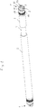
- the locking bar shown is a telescopic, i. H. Locking beam with adjustable length and end fittings 1, which are designed for a load securing system with lashing points that have at least one web.
- the locking bar has two tubes 2 and 3 of the same cross-section, which are connected to one another via a common telescopic tube 4, which is fixedly connected to the tube 3 and axially movable to a limited extent with the tube 2, so that the length of the locking bar can be increased by axially moving the tubes 2 and 3 can be changed within limits to each other.
- the tubes 2 and 3 are each firmly connected at their free ends to a tubular end piece 5 which has the actual end fitting 1.
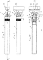
- the tubular end pieces 5 with the components arranged thereon are the same at both ends of the locking bar in the embodiment shown, which is why the structure is detailed below using one of the ends of the locking bar, as shown in FIGS Figures 8-13 is shown, is described.
- a tubular end piece 5 is inserted into the free end of the tube 2 or of the tube 3 and connected there by means of a cross bolt 6 which penetrates both of the tubes 2, 5 and 3, 5 inserted one into the other.
- This cross bolt connecting the components is in the Fig. 10 and 13 not shown.
- annular body 7 Towards the free end of the tubular end piece 5, an annular body 7 is formed, which protrudes radially inwards and outwards over the remaining cross section of the tubular end piece 5.
- a receptacle for a hook-shaped form-locking element 9 which is formed by two spaced-apart legs 8 and which can be pivoted between by means of an axis 10, is formed the legs 8 is arranged.
- the hook-shaped interlocking element 9 is designed as a stamped part and has in plan view ( Fig. 10 / Fig. 13 ) approximately in the shape of an L, with it being attached to the end of the long leg on the axis 10 and having a projection 11 at a distance from the axis 10.
- the arrangement of the form-locking elements 9 is such that their short legs in the in Fig. 13 shown closed position abut each other and then their long legs are approximately parallel and run in the longitudinal direction of the locking bar.
- the axes 10, which at the same time form the axes of rotation for the hook-shaped form-fitting elements 9, are arranged parallel to one another and at a distance so that the axes of rotation lie in a plane transverse to the longitudinal axis of the locking bar.
- a control element 12 is displaceably mounted, which has an inner section with a circular cross-section, at the end of which a flat body penetrates the annular body 7 and protrudes outwards and which has an indentation 13 at its free end , as well as recesses 14 on its longitudinal sides, which are provided for receiving the projections 11 of the hook-shaped form-locking elements 9.
- the control element 12 has a circumferential groove 15 in the area of its cylindrical body and is designed and arranged such that it is axially displaceable but not rotatable within the annular body 7, so that the orientation of the front flat part of the control element 12 with the front Indentation 13 to the form-locking elements 9 always remains the same.
- the control element 12 is acted upon by force in the extension direction by a helical spring 16, which is supported on the one hand on the inner end face of the control element 12 and on the other hand on the transverse bolt 6.
- a sleeve 17 is arranged, the part of which facing the annular body 7 forms a locking sleeve and the inwardly directed part forms a guide on the tube 2 or 3.
- a helical spring 18 is arranged between the end face of the tube 2 and a shoulder within the sleeve 7, which applies force to the sleeve 17 in the direction of the annular body 7 and, if there is no obstacle there, also pushes it into contact with the annular body 7.
- the sleeve 17 has a circumferential groove 19 on the inside, which can be brought into the height of circular recesses 20 in the tubular end piece 5 by longitudinal displacement on the tubular end piece 5, such that blocking bodies in the form of balls 21, which are each arranged in the recesses 20 , can be brought into an unlocking position in the free spaces formed by the groove 17 and the recesses 20 or, when the sleeve 17 is advanced to the annular body 7 and the balls 21 are arranged in the recesses 20 and the groove 15, the movement of the Lock control element 12 in relation to the end piece. Then the sleeve 17 pushed over the recesses 20 holds the balls 21 in this position until the sleeve 17 is withdrawn by manual intervention against the force of the helical spring 18.
- FIG. 8-13 not only the end of the locking bar but also the associated lashing point is shown in the form of a lashing fitting.
- the lashing fitting shown is a rail 22 which has a groove 23 over its entire length which is interrupted at intervals by webs 24.
- the groove 23 is like that Figures 11-13 make clear, so deep that a web 24 can be engaged from behind by the hook-shaped form-locking elements 9, as shown in FIG Fig. 13 is shown.
- the locking bar is with the End fitting in the starting position, as determined by the Figs. 2-4 is shown, with the hook-shaped interlocking elements 9 in their open position and the control element 12 extended towards the free end with the front indentation 13 of the control element 12 to rest on a web 24 of a lashing point.
- the sleeve 17 is fixed on the end piece 5 by the balls 21 lying in the groove 19, some of which lie in the recesses 20 and some in the groove 19.
- the locking bar is pushed further towards the web 24 against the spring force of the helical spring 16, whereby, since the web 24 is stationary, the control element 12 is pushed into the interior of the tubular end piece 5 and In doing so, move the hook-shaped form-locking elements 9 into the closed position via the projections 11 located in the recesses 14, in which the end faces of the short legs of the form-locking elements 9 rest against one another and the web 24 through the front indentation 13 of the control element 12 in connection with the two Pages comprehensive hook-shaped form-locking elements 9 in the end fitting 1 fixed positively.
- the groove 15 has come into overlap with the recesses 20 when pushed into the tubular end piece 5, the balls 21 located in the recesses 20 have moved radially inward due to the spring force of the helical spring 18, so that the balls 21 in the groove 15 and the Recesses 20 are arranged and the locking part of the sleeve 17 has been pushed over the recesses 20 by the spring force and the sleeve 17 rests on the annular body 7.
- the connection of the end fitting 1 to the web 24 is in this position the lashing point is positively secured and can only be released through targeted manual intervention.
Landscapes
- Engineering & Computer Science (AREA)
- Transportation (AREA)
- Mechanical Engineering (AREA)
- Package Frames And Binding Bands (AREA)
- Mutual Connection Of Rods And Tubes (AREA)
- Refuge Islands, Traffic Blockers, Or Guard Fence (AREA)
- Hooks, Suction Cups, And Attachment By Adhesive Means (AREA)
Description
- Die Erfindung betrifft einen Sperrbalken für ein Ladungssicherungssystem mit Zurrpunkten, welche mindestens einen Steg aufweisen, mit hakenförmigen Formschlusselementen an den Enden des Sperrbalkens.
- Ladungssicherungssysteme für Fahrzeuge zählen heutzutage in unterschiedlichen Ausführungen zum Stand der Technik. Die Ladungssicherung erfolgt dabei mit Zurrgurten, Netzen, Sperrbalken und dergleichen, wobei sich auf dem Markt unterschiedliche Systeme etabliert haben, die sich im Wesentlichen in der Ausbildung der Zurrpunkte, d. h. der Punkte unterscheiden, mit welchen die Ladungssicherungen fahrzeugseitig festgelegt werden.
- Ein bekanntes Ladungssicherungssystem ist das sogenannte "Airline-System", welches fahrzeugseitig festgelegte Zurrschienen aufweist, welche eine Vielzahl von Zurrpunkten über die Länge der Schiene bilden. Aus
EP 2 907 696 A1 zählt ein Sperrbalken zum Stand der Technik, welcher zur Verwendung mit Airline-Systemen vorgesehen ist und welcher in einfacher und sicherer Weise in solchen Airline-Schienen im Fahrzeug festgelegt werden kann. - Für andere Sicherungssysteme, beispielsweise mit Rundloch-Zurrschienen oder Schlüsselloch-Zurrschienen, ist dieser Sperrbalken aufgrund der Inkompatibilität der Zurrpunkte bzw. der Zurrbeschläge nicht geeignet.
- Es ist ein Ladungssicherungssystem verbreitet, bei welchem die Zurrpunkte durch einen Steg gebildet sind, sei es, dass Einzelzurrpunkte durch einen Beschlag mit einer Längsausnehmung, die durch einen Quersteg unterbrochen ist, gebildet sind oder aber Schienen Verwendung finden, welche eine tiefe Längsnut aufweisen, die durch Stege unterbrochen ist. Diese Stege dienen zum Festlegen von Ladungssicherungsbeschlägen, welche typischerweise hakenförmig ausgebildet sind und in montiertem Zustand einerseits einen Steg übergreifen, andererseits seitlich in der Ausnehmung bzw. Nut festgelegt sind.
- Aus
US 3,130,690 A undDE 1 806 986 U zählen Sperrbalken zum Stand der Technik, an deren Enden hackenförmige Formschlusselemente angeordnet sind, die nach Art einer Zange an einem wandseitig des Fahrzeugs angeordneten Steg, diesen umgreifend formschlüssig festlegbar sind. Die Steuerung dieser Hacken erfolgt manuell über entsprechende Handhaben, die entgegen Federkraft zum Öffnen verschwenkt bzw. verschoben werden können.US 3,130,690 A1 offenbart den Oberbegriff des Anspruchs 1. Ein ähnliches Ladungssicherungssystem für Fahrzeuge ist ausUS 2,896,554 A bekannt. - Aufgabe der vorliegenden Erfindung ist es, einen Sperrbalken für ein Ladungssicherungssystem mit Zurrpunkten der vorbeschriebenen Art, also welche mindestens einen Steg aufweisen, bereitzustellen, welche einerseits hohe Kräfte aufnehmen können, andererseits sicher und einfach zu befestigen sind und die sich nicht von selbst lösen können.
- Diese Aufgabe wird gemäß der Erfindung durch einen Sperrbalken mit den in Anspruch 1 angegebenen Merkmalen gelöst. Vorteilhafte Ausgestaltungen der Erfindung ergeben sich aus den Unteransprüchen, der nachfolgenden Beschreibung und den Zeichnungen.
- Der erfindungsgemäße Sperrbalken ist für ein Ladungssicherungssystem mit Zurrpunkten vorgesehen, welche mindestens einen Steg aufweisen. Beispielsweise handelt es sich hierbei um Zurrpunkte, welche durch einen Beschlag gebildet sind, welcher eine längliche Ausnehmung aufweist, die durch einen Steg unterbrochen ist, wobei der Steg derart beabstandet von der Montagefläche ist, dass ein hakenförmiger Beschlag diesen hintergreifen kann. Dabei wird der erfindungsgemäße Sperrbalken vorteilhaft in Verbindung mit im Fahrzeug befestigten Schienen verwendet, welche zum Beispiel senkrecht verlaufen, eine vergleichsweise tiefe durchgehende Nut aufweisen und die nahe ihrer offenen Seite durch im Abstand über die Länge angeordnete Querstege unterbrochen ist. Derartige Schienen und Beschläge sind beispielsweise unter der Bezeichnung "Pro Safe" von der Firma Sortimo im Markt verfügbar.
- Der Sperrbalken weist hakenförmige Formschlusselemente an den Enden auf und ist dadurch gekennzeichnet, dass an mindestens einem Ende des Sperrbalkens, vorzugsweise jedoch an beiden Enden des Sperrbalkens jeweils zwei zueinander offene hakenförmige Formschlusselemente angeordnet sind, welche in einer ersten offenen Stellung zur Aufnahme eines Stegs des Zurrpunktes zumindest an ihren freien Enden beabstandet sind und die in einer zweiten geschlossenen Stellung den Steg formschlüssig umgreifend angeordnet sind. In letzterer Stellung sind die Formschlusselemente vorzugsweise verriegelbar, damit ein unbeabsichtigtes Lösen sicher ausgeschlossen ist.
- Grundgedanke dabei ist es, den Sperrbalken vorzugsweise an seinen beiden Enden in sämtliche Richtungen formschlüssig in einem Zurrpunkt festzulegen, um sicherzustellen, dass sich dieser nicht versehentlich löst und um hohe Kräfte sicher aufnehmen zu können. Dabei ist die Konstruktion der Endbeschläge so gestaltet, dass zwei hakenförmige Formschlusselemente gegenüberliegend angeordnet sind, also so, dass quasi ein Haken den Steg von der einen und der andere gleichzeitig von der anderen Seite umgreifen kann und somit unabhängig von der Montagestellung in sämtliche Richtungen formschlüssig sichert. Dabei ist eine offene Stellung vorgesehen, in welcher die Haken zumindest an ihren freien Enden beabstandet sind, sodass der Beschlag offen zur Aufnahme eines Steges ist und eine geschlossene Stellung, in welcher der Steg von den beiden hakenförmigen Formschlusselementen vollständig oder nahezu vollständig umschlossen ist, der Sperrbalken also formschlüssig am Steg festgelegt ist. Vorzugsweise sind diese Endbeschläge an beiden Enden des Sperrbalkens vorgesehen, es kann jedoch auch nur an einem Ende ein solcher, den Steg vollständig umfassender Endbeschlag mit zwei zueinander offenen hakenförmigen Formschlusselementen vorgesehen sein und am anderen Ende ein einfacher Haken oder anderer geeigneter Beschlag. Unter "hakenförmig" im Sinne der vorliegenden Erfindung ist auch eine vereinfachte Hakenform, beispielsweise eine L-Form zu verstehen, wesentlich ist, dass von zwei hakenförmigen
Formschlusselementen in geschlossener Stellung ein Freiraum zur Aufnahme des Steges gebildet ist, der so geschlossen ist, dass der Steg nicht versehentlich oder kraftbedingt entweichen kann. - Um eine sichere und zugleich einfache Handhabung des Sperrbalkens beim Festlegen in einem Zurrpunkt zu gewährleisten, ist gemäß der Erfindung ein Steuerelement zur Steuerung der Stellung der Formschlusselemente vorgesehen, welches in Längsrichtung des Sperrbalkens axial verschiebbar angeordnet ist und welches durch einen Steg eines Zurrpunktes, an dem das Ende des Sperrbalkens festgelegt werden soll, : steuerbar ist. Bei geeigneter Ausbildung eines solchen Steuerelementes, wie weiter unten noch im Einzelnen ausgeführt, kann eine nahezu selbsttätige Festlegung eines Sperrbalkenendes am Steg des Zurrpunktes erreicht werden, einfach indem der Sperrbalken mit seinem Ende auf den Steg eines Zurrpunktes aufgesetzt wird, wobei der Steg bei weiterem Andrücken des Sperrbalkens das Steuerelement in Richtung des Sperrbalkens bewegt, wodurch die hakenförmigen Formschlusselemente von der offenen Stellung in die geschlossene Stellung bewegt werden, in welcher sie den Steg umschließen und somit formschlüssig umgreifend angeordnet sind.
- Besonders vorteilhaft ist es, wenn der Sperrbalken gemäß einer Weiterbildung der Erfindung zur Längenanpassung an den Abstand zweier Zurrpunkte teleskopierbar ausgebildet ist. Hierzu ist er aus teleskopierbaren Rohren aufgebaut, die vorzugsweise begrenzt zueinander beweglich sind, sodass der Sperrbalken nicht in zwei Teile auseinander gezogen werden kann, sondern nur in vorgegebenen Maßen längenveränderbar ist. Letzteres ist im Übrigen auch zweckmäßig, um ein Festlegen an beiden Enden jeweils mittels zweier hakenförmiger Formschlusselemente zu realisieren. Hierzu weist der Sperrbalken vorteilhaft zwei Rohre auf, die durch ein gemeinsames Teleskoprohr verbunden sind, d. h. zwei Rohre, die entweder ein gemeinsames Teleskoprohr an beiden Seiten übergreifen oder in ein solches eingesteckt sind. Vorzugsweise ist dabei ein Rohr fest mit dem Teleskoprohr verbunden und das andere Rohr axial begrenzt beweglich. Grundsätzlich können jedoch auch beide Rohre axial begrenzt beweglich mit dem Teleskoprohr verbunden sein. Eine Festverbindung zweier solcher Rohre kann in einfacher Weise durch einen beide Rohre durchsetzenden Querstift oder Niet gebildet sein, eine axial begrenzt bewegliche Verbindung durch einen Querstift, der in einem Rohr festgelegt und im anderen Rohr in einer Längsnut geführt ist. Die Enden der Längsnut begrenzen dann den Ausfahrweg.
- Grundsätzlich kann die Mechanik, welche die Bewegung zwischen dem Steuerelement und den hakenförmigen Formschlusselementen bewirkt, am Ende eines Rohres des Sperrbalkens vorgesehen sein, besonders vorteilhaft ist es jedoch, wenn diese an einem Ende eines rohrförmigen Endstückes vorgesehen ist, welches fest mit dem daran anschließenden Rohr des Sperrbalkens verbunden ist, wobei an diesem rohrförmigen Endstück die hakenförmigen Formschlusselemente angeordnet sind und das Steuerelement zumindest teilweise aufgenommen und axial begrenzt beweglich geführt ist. Diese Ausgestaltung ist insbesondere fertigungstechnisch von Vorteil, da ein solches rohrförmiges Endstück mit der daran angeordneten Mechanik für die hakenförmigen Formschlusselemente sowie das Steuerelement unabhängig von der Längendimensionierung des Sperrbalkens gefertigt werden kann, sodass Sperrbalken unterschiedlicher Länge mit gleichem Endstück versehen werden können. Auch ist es mit dieser Ausgestaltung relativ einfach möglich, Sondermaße des Sperrbalkens zu realisieren, und zwar unter weitgehender Beibehaltung vorhandener Bauteile.
- Die mechanische Kopplung zwischen den hakenförmigen Formschlusselementen und dem Steuerelement kann auf unterschiedliche Weise erfolgen, beispielsweise durch Bahnführungen zwischen den Bauteilen, besonders vorteilhaft ist es jedoch, wenn die hakenförmigen Formschlusselemente an ihrem sperrbalkenseitigen Ende nahe dem freien Ende des Endstückes an diesem angelenkt sind, und zwar derart, dass deren Schwenkachsen parallel zueinander und vorzugsweise in einer Querebene angeordnet sind, welche senkrecht zur Längsachse des Sperrbalkens liegt.
- Bei einer solchen Anordnung kann das Steuerelement mit den hakenförmigen Formschlusselementen vorteilhaft derart bewegungsgekoppelt werden, dass beim Einfahren des Steuerelementes in den Sperrbalken die hakenförmigen Formschlusselemente von ihrer offenen in die geschlossene Stellung bewegt werden und damit den Steg des Zurrpunktes vollständig oder nahezu vollständig umgreifen.
- Das Steuerelement, das zapfenförmig oder auch als Blechteil ausgebildet sein kann, weist vorteilhaft an seinen Längsseiten jeweils eine Ausnehmung auf, in welche ein Vorsprung eingreift, welcher an einem hakenförmigen Formschlusselement vorgesehen und mit radialem Abstand zur Schwenkachse angeordnet ist. Dabei ist der Vorsprung nicht nur mit radialem Abstand zur Schwenkachse, sondern im Wesentlichen auch quer zur Längserstreckung des hakenförmigen Formschlusselementes angeordnet, um die Längsbewegung des Steuerelementes in eine Schwenkbewegung des Formschlusselementes umsetzen zu können. Besonders vorteilhaft ist es dabei, wenn die Ausnehmungen an den beiden gegenüberliegenden abgewandten Längsseiten des Steuerelementes auf gleicher Höhe angeordnet sind, da dann bei geeigneter konstruktiver Ausgestaltung die hakenförmigen Formschlusselemente für beide Seiten gleich ausgebildet sein können, d. h., typischerweise nur formgleiche Stanzteile zu fertigen sind.
- Vorteilhaft ist das Steuerelement in Ausfahrrichtung federkraftbeaufschlagt, was beispielsweise durch eine Schraubenfeder gebildet sein kann, die sich einerseits am inneren Ende des Steuerelementes und andererseits zum Beispiel an einem Querbolzen abstützt, mit welchem das Rohrendstück mit dem Rohr verbunden ist.
- Um sicherzustellen, dass sich die Formschlussverbindung zwischen den hakenförmigen Formschlusselementen und dem Steg nicht unbeabsichtigt löst, ist gemäß einer vorteilhaften Weiterbildung der Erfindung eine vorzugsweise selbsttätig wirkende Verriegelung vorgesehen. Eine solche Verriegelung ist durch mindestens einen Sperr- oder Riegelkörper, vorzugsweise in Form einer Kugel, gebildet sowie mindestens einer entsprechend der Größe des Sperrkörpers dimensionierten Ausnehmung im rohrförmigen Endstück, oder, wenn ein solches nicht vorgesehen ist, im Rohrende. Weiterhin ist fluchtend zu der Ausnehmung im Endstück eine seitliche Ausnehmung, vorzugsweise eine Nut, im Steuerelement angeordnet, sodass dann, wenn das Steuerelement durch axiale Einfahrbewegung in den Sperrbalken mit seiner Ausnehmung bzw. der Nut in Höhe der Ausnehmung des Endstückes gelangt, dieser Sperrkörper sowohl in der Ausnehmung des Endstückes als auch gleichzeitig in der Ausnehmung des Steuerelementes angeordnet ist und die beiden Teile damit in axialer Richtung bewegungskoppelt, d. h. das Steuerelement in Bezug auf das Endstück festliegt. In dieser Stellung ist die Bewegung des Steuerelementes gesperrt und somit auch ein Bewegen der hakenförmigen Formschlusselemente von der geschlossenen in die offene Stellung nicht möglich.
- Diese vorbeschriebene verriegelte Stellung kann vorteilhaft dadurch gesichert werden, dass gemäß einer Weiterbildung der Erfindung umfänglich des Endstückes bzw. des Endrohres, wenn kein solches Endstück vorgesehen ist, eine Riegelhülse axial verschiebbar vorgesehen ist, welche in einer federbelasteten Endstellung den Sperrkörper in seiner Sperrstellung formschlüssig verriegelt. Dabei ist vorteilhaft die Riegelhülse derart federkraftbeaufschlagt, dass sie selbsttätig in die formschlüssig verriegelnde Sperrstellung geschoben wird und nur entgegen dieser Federkraft durch beispielsweise manuellen Eingriff so weit zurückgezogen werden kann, dass ein Freiraum für einen Teil des Sperrkörpers gebildet ist, der dann aus der seitlichen Ausnehmung des Steuerelementes austreten kann, sodass das Steuerelement nicht mehr formschlüssig festgelegt ist. In der Praxis genügt also das axiale Verschieben entgegen Federkraft von Hand, um den Sperrbalken wieder zu lösen, da, sobald der Sperrkörper außer Eingriff mit der Ausnehmung des Steuerelementes gelangt, dieses federkraftbedingt aus dem Sperrbalken herausgeschoben wird bzw. der Sperrbalken gegenüber dem Steuerelement, welches sich am Steg des Zurrpunktes abstößt, zurückgeschoben wird und dabei die hakenförmigen Formschlusselemente in ihre offene, den Steg freigebende Stellung geschwenkt werden. Vorteilhaft sind über den Umfang verteilt mehrere Sperrkörper vorgesehen, die in entsprechenden Ausnehmungen im Endstück bzw. Endrohr vorgesehen sind, die entweder in eine umlaufende Nut des Steuerelementes eingreifen oder bei Freigabe des Steuerelementes in eine umlaufende Nut der Riegelhülse austreten.
- Die Erfindung ist nachfolgend anhand eines in den Zeichnungen dargestellten Ausführungsbeispiels näher erläutert. Es zeigen:
- Fig. 1
- in stark vereinfachter schematischer perspektivischer Darstellung einen Sperrbalken gemäß der Erfindung,
- Fig. 2
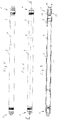
- eine Seitenansicht auf den Sperrbalken gemäß
Fig. 1 mit geöffneten Endbeschlägen, - Fig. 3
- eine gegenüber
Fig. 2 um 90° gedrehte Seitenansicht des Sperrbalkens, - Fig. 4
- einen Schnitt längs der Schnittlinien A - A in
Fig. 3 , - Fig. 5
- den Sperrbalken in Darstellung gemäß
Fig. 2 mit geschlos-senen Endbeschlägen, - Fig. 6
- den Sperrbalken gemäß
Fig. 5 in Darstellung entsprechendFig. 3 , - Fig. 7
- einen Schnitt längs der Schnittlinie A - A in
Fig. 6 , - Fig. 8
- in vergrößerter Darstellung ein Ende des Sperrbalkens in Darstellung entsprechend
Fig. 6 mit zugehöriger Zurrbeschlagschiene, - Fig. 9
- eine gegenüber
Fig. 8 um 90° gedrehte Darstellung des Sperrbalkens, - Fig. 10
- einen Schnitt längs der Schnittlänge A - A in
Fig. 8 , - Fig. 11
- den Sperrbalken in Darstellung gemäß
Fig. 8 mit geschlossener, aber noch nicht verriegelter Stellung des Endbeschlages, - Fig. 12
- eine gegenüber
Fig. 11 um 90° gedrehte Darstellung und - Fig. 13
- einen Schnitt längs der Schnittlinie A - A in
Fig. 11 . - Bei dem dargestellten Sperrbalken handelt es sich um einen teleskopierbaren, d. h. in seiner Länge veränderbaren Sperrbalken mit Endbeschlägen 1, welche für ein Ladungssicherungssystem mit Zurrpunkten ausgelegt sind, die mindestens einen Steg aufweisen. Der Sperrbalken weist zwei Rohre 2 und 3 gleichen Querschnitts auf, die über ein gemeinsames Teleskoprohr 4 miteinander verbunden sind, welches mit dem Rohr 3 fest und mit dem Rohr 2 axial begrenzt beweglich verbunden ist, damit die Länge des Sperrbalkens durch axiales Verschieben der Rohre 2 und 3 zueinander in Grenzen geändert werden kann.
- Die Rohre 2 und 3 sind an ihren freien Enden jeweils fest mit einem rohrförmigen Endstück 5 verbunden, welches den eigentlichen Endbeschlag 1 aufweist. Die rohrförmigen Endstücke 5 mit den daran angeordneten Bauteilen sind bei der dargestellten Ausführungsform an beiden Enden des Sperrbalkens gleich, weshalb im Folgenden der Aufbau im Einzelnen anhand eines der Enden des Sperrbalkens, wie es in den
Fig. 8 - 13 dargestellt ist, beschrieben ist. - Ein rohrförmiges Endstück 5 ist in das freie Ende des Rohres 2 bzw. des Rohres 3 eingesteckt und dort mittels eines Querbolzens 6 verbunden, welcher beide der ineinander gesteckten Rohre 2, 5 bzw. 3, 5 durchsetzt. Dieser die Bauteile verbindende Querbolzen ist in den
Fig. 10 und13 nicht dargestellt. - Zum freien Ende des rohrförmigen Endstückes 5 hin ist ein ringförmiger Körper 7 gebildet, welcher radial nach innen und nach außen den übrigen Querschnitt des rohrförmigen Endstückes 5 überragt. Auf diesem ringförmigen Körper 7 ist stirnseitig eine durch zwei beabstandete Schenkel 8 gebildete Aufnahme für ein hakenförmiges Formschlusselement 9 gebildet, welches mittels einer Achse 10 schwenkbar zwischen den Schenkeln 8 angeordnet ist. Das hakenförmige Formschlusselement 9 ist als Stanzteil ausgebildet und hat in Draufsicht (
Fig. 10 /Fig. 13 ) etwa die Form eines L, wobei es am Ende des langen Schenkels an der Achse 10 befestigt ist und mit Abstand zur Achse 10 einen Vorsprung 11 aufweist. Die Anordnung der Formschlusselemente 9 ist so, dass ihre kurzen Schenkel in der inFig. 13 dargestellten geschlossenen Stellung aneinanderstoßen und dann ihre langen Schenkel etwa parallel sind und in Längsrichtung des Sperrbalkens verlaufen. Die Achsen 10, welche zugleich die Drehachsen für die hakenförmigen Formschlusselemente 9 bilden, sind parallel zueinander und mit Abstand angeordnet, sodass die Drehachsen in einer Ebene quer zur Längsachse des Sperrbalkens liegen. - Innerhalb des rohrförmigen Endstücks 5 ist ein Steuerelement 12 verschiebbar gelagert, welches einen inneren, im Querschnitt kreisrunden Abschnitt aufweist, an dessen Stirnseite sich ein den ringförmigen Körper 7 durchsetzender und nach außen vorspringender flacher Körper anschließt, welcher an seinem freien Ende eine stirnseitige Einbuchtung 13 aufweist, sowie an seinen Längsseiten Ausnehmungen 14, welche zur Aufnahme der Vorsprünge 11 der hakenförmigen Formschlusselemente 9 vorgesehen sind. Weiterhin weist das Steuerelement 12 im Bereich seines zylindrischen Körpers eine umlaufende Nut 15 auf und ist so ausgebildet und angeordnet, dass es innerhalb des ringförmigen Körpers 7 axial verschiebbar, jedoch nicht drehbar ist, sodass die Orientierung des vorderen flachen Teils des Steuerelementes 12 mit der vorderen Einbuchtung 13 zu den Formschlusselementen 9 stets gleich bleibt. Das Steuerelement 12 ist in Ausfahrrichtung durch eine Schraubenfeder 16 kraftbeaufschlagt, welche sich einerseits an der inneren Stirnseite des Steuerelementes 12 und andererseits an dem Querbolzen 6 abstützt.
- Am Außenumfang des rohrförmigen Endstückes 5 ist eine Hülse 17 angeordnet, deren zum ringförmigen Körper 7 weisender Teil eine Riegelhülse bildet und deren nach innen gerichteter Teil eine Führung auf dem Rohr 2 bzw. 3 bildet. Zwischen der Stirnseite des Rohres 2 und einem Absatz innerhalb der Hülse 7 ist eine Schraubenfeder 18 angeordnet, welche die Hülse 17 in Richtung zum ringförmigen Körper 7 kraftbeaufschlagt und diese, wenn dort kein Hindernis ist, auch bis zur Anlage an den ringförmigen Körper 7 schiebt. Die Hülse 17 weist innen eine umlaufende Nut 19 auf, welche durch Längsverschieben auf dem rohrförmigen Endstück 5 in Höhe von kreisrunden Ausnehmungen 20 im rohrförmigen Endstück 5 bringbar ist, derart, dass Sperrkörper in Form von Kugeln 21, welche jeweils in den Ausnehmungen 20 angeordnet sind, in eine entsperrende Stellung in die durch die Nut 17 und die Ausnehmungen 20 gebildeten Freiräume bringbar sind oder, wenn die Hülse 17 bis zum ringförmigen Körper 7 vorgeschoben ist und die Kugeln 21 in den Ausnehmungen 20 und der Nut 15 angeordnet sind, die Bewegung des Steuerelementes 12 in Bezug auf das Endstück verriegeln. Dann hält die über die Ausnehmungen 20 geschobene Hülse 17 die Kugeln 21 in dieser Position, solange, bis die Hülse 17 durch manuellen Eingriff entgegen der Kraft der Schraubenfeder 18 zurückgezogen wird.
- In den
Fig. 8 - 13 ist nicht nur das Sperrbalkenende, sondern auch der zugehörige Zurrpunkt in Form eines Zurrbeschlages dargestellt. Bei dem dargestellten Zurrbeschlag handelt es sich um eine Schiene 22, welche über ihre gesamte Länge eine Nut 23 aufweist, die in Abständen durch Stege 24 unterbrochen ist. Die Nut 23 ist, wie dieFig. 11 - 13 verdeutlichen, so tief, dass ein Steg 24 von den hakenförmigen Formschlusselementen 9 hintergriffen werden kann, so wie dies inFig. 13 dargestellt ist. - Zum Festlegen eines Endbeschlages 1 des Sperrbalkens im Zurrpunkt, also am Steg 24 der Schiene 22, wird der Sperrbalken mit dem Endbeschlag in der Ausgangsstellung, wie er anhand der
Fig. 2 - 4 dargestellt ist, mit den hakenförmigen Formschlusselementen 9 in ihrer geöffneten Stellung und dem zum freien Ende hin ausgefahrenen Steuerelement 12 mit der stirnseitigen Einbuchtung 13 des Steuerelementes 12 zur Anlage an einen Steg 24 eines Zurrpunktes gebracht. Dabei sind die Formschlusselemente 9, wie in denFig. 2 und 4 sichtbar, weit aufgeschwenkt, das Steuerelement 12 ist durch die Federkraft der Feder 16 aus dem Sperrbalken herausgeschoben und hat über die in den Ausnehmungen 14 angeordneten Vorsprünge 11 die Formschlusselemente 9 ausgeschwenkt. Die Hülse 17 ist durch die in der Nut 19 liegenden Kugeln 21, welche teils in den Ausnehmungen 20, teils in der Nut 19 liegen, auf dem Endstück 5 festgelegt. Sobald der Steg 24 die vordere Einbuchtung 13 des Steuerelementes 12 erreicht, wird der Sperrbalken entgegen Federkraft der Schraubenfeder 16 weiter zum Steg 24 hin geschoben, wodurch, da der Steg 24 feststehend ist, das Steuerelement 12 in das Innere des rohrförmigen Endstückes 5 geschoben wird und dabei über die in den Ausnehmungen 14 liegenden Vorsprünge 11 die hakenförmigen Formschlusselemente 9 in die geschlossene Stellung verfahren, in welcher die Stirnseiten der kurzen Schenkel der Formschlusselemente 9 aneinander anliegen und der Steg 24 durch die vordere Einbuchtung 13 des Steuerelementes 12 in Verbindung mit den von beiden Seiten umfassenden hakenförmigen Formschlusselementen 9 im Endbeschlag 1 formschlüssig festgelegt. Dabei ist die Nut 15 beim Einschieben in das rohrförmige Endstück 5 in Überdeckung mit den Ausnehmungen 20 gekommen, die in den Ausnehmungen 20 befindlichen Kugeln 21 sind aufgrund der Federkraft der Schraubenfeder 18 radial nach innen ausgewichen, sodass die Kugeln 21 in der Nut 15 und den Ausnehmungen 20 angeordnet sind und der verriegelnde Teil der Hülse 17 durch die Federkraft über die Ausnehmungen 20 geschoben worden ist und die Hülse 17 am ringförmigen Körper 7 anliegt. In dieser Stellung ist die Verbindung des Endbeschlages 1 mit dem Steg 24 des Zurrpunktes formschlüssig gesichert und kann nur durch gezielten manuellen Eingriff gelöst werden. - Zum Lösen ist die Hülse 17 manuell so weit zurückzuziehen, dass die Nut 19 in Überdeckung mit den Ausnehmungen 20 kommt, sodass die Kugeln 21 radial nach außen ausweichen können und das Steuerelement 12 in seiner axialen Bewegung nach außen freigegeben wird. Diese Bewegung erfolgt aufgrund der Federkraft der Schraubenfeder 16 und spreizt die Formschlusselemente 9 in ihre geöffnete Stellung, womit die eingangs beschriebene Ausgangsstellung wieder erreicht ist.
-
- 1
- Endbeschläge
- 2
- langes Rohr
- 3
- kurzes Rohr
- 4
- Teleskoprohr
- 5
- rohrförmiges Endstück
- 6
- Querbolzen
- 7
- ringförmiger Körper
- 8
- Schenkel
- 9
- hakenförmiges Formschlusselement
- 10
- Achse
- 11
- Vorsprung an 9
- 12
- Steuerelement
- 13
- stirnseitige Einbuchtung am Steuerelement
- 14
- seitliche Ausnehmungen am Steuerelement
- 15
- umlaufende Nut am Steuerelement
- 16
- Schraubenfeder
- 17
- Hülse
- 18
- Schraubenfeder
- 19
- Nut in der Hülse
- 20
- Ausnehmungen im rohrförmigen Endstück 5
- 21
- Kugeln
- 22
- Schiene
- 23
- Nut
- 24
- Stege
Claims (11)
- Sperrbalken für ein Ladungssicherungssystem mit Zurrpunkten, welche mindestens einen Steg (24) aufweisen, mit hakenförmigen Formschlusselementen (9) an den Enden des Sperrbalkens, wobei an mindestens einem, vorzugsweise beiden Enden des Sperrbalkens zwei zueinander offene hakenförmige Formschlusselemente (9) angeordnet sind, welche in einer ersten offenen Stellung zur Aufnahme eines Stegs (24) zumindest an ihren freien Enden beabstandet und in einer zweiten geschlossenen, den Steg (24) formschlüssig umgreifend angeordnet sind, dadurch gekennzeichnet, dass ein Steuerelement (12) zur Steuerung der Stellung der Formschlusselemente (9) vorgesehen ist, welches in Längsrichtung des Sperrbalkens axial verschiebbar angeordnet ist und durch einen Steg (24) eines Zurrpunktes steuerbar ist.
- Sperrbalken nach Anspruch 1, dadurch gekennzeichnet, dass die zweite geschlossene Stellung verriegelbar ist.
- Sperrbalken nach Anspruch 1 oder 2, dadurch gekennzeichnet, dass der Sperrbalken zur Längenänderung vorzugsweise begrenzt zueinander teleskopierbare Rohre (2, 4) aufweist.
- Sperrbalken nach einem der vorhergehenden Ansprüche, dadurch gekennzeichnet, dass der Sperrbalken zwei Rohre (2, 3) aufweist, die durch ein gemeinsames Teleskoprohr (4) verbunden sind und dass das Teleskoprohr (4) vorzugsweise mit dem einen Rohr (3) fest und mit dem anderen Rohr (2) axial begrenzt beweglich verbunden ist.
- Sperrbalken nach einem der vorhergehenden Ansprüche, dadurch gekennzeichnet, dass mindestens an einem Ende ein rohrförmiges Endstück (5) vorgesehen ist, das fest mit dem daran anschließenden Rohr (2, 3) des Sperrbalkens verbunden ist, an welchem Endstück (5) die hakenförmigen Formschlusselemente (9) angeordnet sind und in dem das Steuerelement (12) zumindest teilweise aufgenommen und axial begrenzt beweglich geführt ist.
- Sperrbalken nach einem der vorhergehenden Ansprüche, dadurch gekennzeichnet, dass die hakenförmigen Formschlusselemente (9) an ihren sperrbalkenseitigen Enden nahe dem freien Ende des Endstücks (5) an diesem angelenkt sind, derart, dass deren Schwenkachsen parallel zueinander und in einer Querebene angeordnet sind, welche senkrecht zur Längsachse des Sperrbalkens liegt.
- Sperrbalken nach einem der vorhergehenden Ansprüche, dadurch gekennzeichnet, dass das Steuerelement (12) mit den hakenförmigen Formschlusselementen (9) derart bewegungsgekoppelt ist, dass beim Einfahren des Steuerelements (12) in den Sperrbalken die hakenförmigen Formschlusselemente (9) von ihrer offenen in die geschlossene Stellung bewegt werden.
- Sperrbalken nach einem der vorhergehenden Ansprüche, dadurch gekennzeichnet, dass das Steuerelement (12) Ausnehmungen (14) an seinen Längsseiten aufweist, in welche Vorsprünge (11) eingreifen, die an den hakenförmigen Formschlusselementen (9) mit radialem Abstand zu deren Schwenkachse angeordnet sind.
- Sperrbalken nach einem der vorhergehenden Ansprüche, dadurch gekennzeichnet, dass das Steuerelement (12) in Ausfahrrichtung federkraftbeaufschlagt ist.
- Sperrbalken nach einem der vorhergehenden Ansprüche, dadurch gekennzeichnet, dass mindestens ein Sperrkörper (21), vorzugsweise in Form einer Kugel (21) in mindestens einer Ausnehmung (20) eines Endstücks (5) angeordnet ist, welcher die Axialbewegung zwischen dem Steuerelement (12) und dem Endstück (5) sperrt, wenn der Sperrkörper (21) in der Ausnehmung (20) des Endstücks (5) und in einer seitlichen Ausnehmung, vorzugsweise Nut (15), des Steuerelements (12) angeordnet ist.
- Sperrbalken nach Anspruch 10, dadurch gekennzeichnet, dass umfänglich des Endstücks (5)eine Riegelhülse (17) axial verschiebbar vorgesehen ist, welche in einer federbelasteten Endstellung den Sperrkörper (21) in seiner Sperrstellung formschlüssig verriegelt und welche in einer entgegen der Federkraft gebildeten Entriegelstellung einen Freiraum (19) für einen Teil des Sperrkörpers (21) bildet.
Applications Claiming Priority (1)
| Application Number | Priority Date | Filing Date | Title |
|---|---|---|---|
| DE202017105457.8U DE202017105457U1 (de) | 2017-09-08 | 2017-09-08 | Sperrbalken |
Publications (2)
| Publication Number | Publication Date |
|---|---|
| EP3453569A1 EP3453569A1 (de) | 2019-03-13 |
| EP3453569B1 true EP3453569B1 (de) | 2021-01-06 |
Family
ID=60081997
Family Applications (1)
| Application Number | Title | Priority Date | Filing Date |
|---|---|---|---|
| EP18190544.9A Active EP3453569B1 (de) | 2017-09-08 | 2018-08-23 | Sperrbalken |
Country Status (4)
| Country | Link |
|---|---|
| US (1) | US11104263B2 (de) |
| EP (1) | EP3453569B1 (de) |
| DE (1) | DE202017105457U1 (de) |
| ES (1) | ES2860809T3 (de) |
Families Citing this family (3)
| Publication number | Priority date | Publication date | Assignee | Title |
|---|---|---|---|---|
| DE102019117464B4 (de) | 2019-02-11 | 2023-05-11 | Frielitz Fahrzeugbau und Zubehör GmbH | Sperrbalken |
| DE202019100808U1 (de) | 2019-02-11 | 2019-04-12 | Frielitz Fahrzeugbau und Zubehör GmbH | Sperrbalken |
| EP3838669B1 (de) * | 2019-12-17 | 2022-12-07 | WISTRA GmbH Cargo Control | Sperrbalken zur anordnung in einem laderaum eines fahrzeugs |
Family Cites Families (11)
| Publication number | Priority date | Publication date | Assignee | Title |
|---|---|---|---|---|
| US2896554A (en) * | 1956-08-17 | 1959-07-28 | Transp Specialties Co | Freight positioning and retaining apparatuses |
| DE1806986U (de) * | 1959-12-31 | 1960-02-25 | Garthe Kg Paul | Festlegeholm fuer ladegut in gueterwagen, insbesondere schienenfahrzeuge. |
| US3130690A (en) * | 1960-12-01 | 1964-04-28 | Johnston Charles Richard | Freight loading apparatus |
| US5688087A (en) * | 1995-11-13 | 1997-11-18 | Advanced Accessory Systems Llc | Pick-up bed rail assembly |
| US6210090B1 (en) * | 2000-05-04 | 2001-04-03 | Gene Wyse | Adjustable load bar |
| EP1207075A1 (de) | 2000-11-20 | 2002-05-22 | Sortimo Speedwave GmbH | Anker zum Befestigen oder Verzurren einer Last an einer Trägerplatte |
| DE10300130A1 (de) | 2003-01-07 | 2004-07-15 | Sortimo Speedwave Gmbh | Halterung für Waren im Laderaum eines Fahrzeugs |
| DE102007048894A1 (de) | 2007-10-11 | 2009-04-16 | Sortimo Speedwave Gmbh | Lösbares Befestigungssystem für Ladegut |
| US20130284685A1 (en) * | 2012-04-26 | 2013-10-31 | Brenda LINES-PINCKNEY | Apparatus for Sheer Rod Attachment |
| EP2907696B1 (de) | 2014-02-18 | 2018-09-05 | WISTRA GmbH Cargo Control | Sperrbalken für ein Ladungssicherungssystem |
| DE202014008510U1 (de) | 2014-10-28 | 2014-12-09 | Bfs Werkzeugsysteme Gmbh | Verbindungsanordnung zwischen stirnseitig aneinander angrenzenden flächigen, insbesondere plattenförmigen, Bauteilen, flächiges Bauteil sowie Bodenbelag |
-
2017
- 2017-09-08 DE DE202017105457.8U patent/DE202017105457U1/de not_active Expired - Lifetime
-
2018
- 2018-08-23 ES ES18190544T patent/ES2860809T3/es active Active
- 2018-08-23 EP EP18190544.9A patent/EP3453569B1/de active Active
- 2018-09-06 US US16/123,020 patent/US11104263B2/en not_active Expired - Fee Related
Non-Patent Citations (1)
| Title |
|---|
| None * |
Also Published As
| Publication number | Publication date |
|---|---|
| DE202017105457U1 (de) | 2017-09-22 |
| EP3453569A1 (de) | 2019-03-13 |
| ES2860809T3 (es) | 2021-10-05 |
| US11104263B2 (en) | 2021-08-31 |
| US20190077296A1 (en) | 2019-03-14 |
Similar Documents
| Publication | Publication Date | Title |
|---|---|---|
| EP1407901B1 (de) | Anhängevorrichtung für Zugfahrzeuge | |
| EP3453569A1 (de) | Sperrbalken | |
| DE102015121018A1 (de) | Längenverstellbare Samerstange | |
| EP3838669B1 (de) | Sperrbalken zur anordnung in einem laderaum eines fahrzeugs | |
| DE3603140A1 (de) | Vorrichtung zur stufenweisen hoehenverstellung eines befestigungs- oder umlenkpunktes fuer einen sicherheitsgurt o. dgl. | |
| EP2907696B1 (de) | Sperrbalken für ein Ladungssicherungssystem | |
| EP3277978B1 (de) | Kettenschloss mit sicherungselement | |
| DE19651562A1 (de) | Anhängekupplung | |
| DE202007000112U1 (de) | Verriegelungsanordnung mit einem schwenkbaren Verriegelungshaken und einer verschiebbaren Haltestange | |
| EP1883078A1 (de) | Vorrichtung zur Handhabung von Kleinbauteilen | |
| EP2216205B1 (de) | Dachlastenträger für Kraftfahrzeuge | |
| DE102008048581B4 (de) | Vorrichtung zum Halten und Sichern von Ladegut, insbesondere in Form einer Sperrstange | |
| EP3795420A1 (de) | Sperrbalken | |
| DE2619830C3 (de) | Abschleppstange für Kraftfahrzeuge | |
| EP0477586A1 (de) | Vorrichtung zum Verbinden von Containern | |
| DE102009051594B4 (de) | Haken, insbesondere für Sicherheitseinrichtungen | |
| DE102010037619A1 (de) | Hoch-Tiefauslegervorrichtung | |
| EP3031985A1 (de) | Montagebügel für gabionen | |
| EP3821687A1 (de) | Kupplungsvorrichtung | |
| DE2321346C3 (de) | Gelenkbeschlag für klappbare Leitern | |
| DE3048862C2 (de) | Federspannvorrichtung zum Vorspannen von Schraubenfedern an Fahrwerksfederungen, insbesondere zum Montieren von Kraftfahrzeugen | |
| DE102010060191A1 (de) | Tisch mit einklappbaren Tischbeinen | |
| DE202012102689U1 (de) | Gestänge | |
| DE102004015596B3 (de) | Teleskopdeichsel | |
| DE102016207498B4 (de) | Koppel zum verbinden zweier bauteile eines fahrzeugsitzes, sowie fahrzeugsitz |
Legal Events
| Date | Code | Title | Description |
|---|---|---|---|
| PUAI | Public reference made under article 153(3) epc to a published international application that has entered the european phase |
Free format text: ORIGINAL CODE: 0009012 |
|
| STAA | Information on the status of an ep patent application or granted ep patent |
Free format text: STATUS: THE APPLICATION HAS BEEN PUBLISHED |
|
| AK | Designated contracting states |
Kind code of ref document: A1 Designated state(s): AL AT BE BG CH CY CZ DE DK EE ES FI FR GB GR HR HU IE IS IT LI LT LU LV MC MK MT NL NO PL PT RO RS SE SI SK SM TR |
|
| AX | Request for extension of the european patent |
Extension state: BA ME |
|
| STAA | Information on the status of an ep patent application or granted ep patent |
Free format text: STATUS: REQUEST FOR EXAMINATION WAS MADE |
|
| 17P | Request for examination filed |
Effective date: 20190912 |
|
| RBV | Designated contracting states (corrected) |
Designated state(s): AL AT BE BG CH CY CZ DE DK EE ES FI FR GB GR HR HU IE IS IT LI LT LU LV MC MK MT NL NO PL PT RO RS SE SI SK SM TR |
|
| GRAJ | Information related to disapproval of communication of intention to grant by the applicant or resumption of examination proceedings by the epo deleted |
Free format text: ORIGINAL CODE: EPIDOSDIGR1 |
|
| STAA | Information on the status of an ep patent application or granted ep patent |
Free format text: STATUS: GRANT OF PATENT IS INTENDED |
|
| GRAP | Despatch of communication of intention to grant a patent |
Free format text: ORIGINAL CODE: EPIDOSNIGR1 |
|
| GRAJ | Information related to disapproval of communication of intention to grant by the applicant or resumption of examination proceedings by the epo deleted |
Free format text: ORIGINAL CODE: EPIDOSDIGR1 |
|
| INTG | Intention to grant announced |
Effective date: 20200428 |
|
| GRAP | Despatch of communication of intention to grant a patent |
Free format text: ORIGINAL CODE: EPIDOSNIGR1 |
|
| GRAJ | Information related to disapproval of communication of intention to grant by the applicant or resumption of examination proceedings by the epo deleted |
Free format text: ORIGINAL CODE: EPIDOSDIGR1 |
|
| STAA | Information on the status of an ep patent application or granted ep patent |
Free format text: STATUS: REQUEST FOR EXAMINATION WAS MADE |
|
| INTG | Intention to grant announced |
Effective date: 20200604 |
|
| GRAP | Despatch of communication of intention to grant a patent |
Free format text: ORIGINAL CODE: EPIDOSNIGR1 |
|
| STAA | Information on the status of an ep patent application or granted ep patent |
Free format text: STATUS: GRANT OF PATENT IS INTENDED |
|
| GRAJ | Information related to disapproval of communication of intention to grant by the applicant or resumption of examination proceedings by the epo deleted |
Free format text: ORIGINAL CODE: EPIDOSDIGR1 |
|
| STAA | Information on the status of an ep patent application or granted ep patent |
Free format text: STATUS: REQUEST FOR EXAMINATION WAS MADE |
|
| GRAP | Despatch of communication of intention to grant a patent |
Free format text: ORIGINAL CODE: EPIDOSNIGR1 |
|
| STAA | Information on the status of an ep patent application or granted ep patent |
Free format text: STATUS: GRANT OF PATENT IS INTENDED |
|
| INTC | Intention to grant announced (deleted) | ||
| INTG | Intention to grant announced |
Effective date: 20200708 |
|
| INTC | Intention to grant announced (deleted) | ||
| INTG | Intention to grant announced |
Effective date: 20200723 |
|
| GRAS | Grant fee paid |
Free format text: ORIGINAL CODE: EPIDOSNIGR3 |
|
| GRAA | (expected) grant |
Free format text: ORIGINAL CODE: 0009210 |
|
| STAA | Information on the status of an ep patent application or granted ep patent |
Free format text: STATUS: THE PATENT HAS BEEN GRANTED |
|
| AK | Designated contracting states |
Kind code of ref document: B1 Designated state(s): AL AT BE BG CH CY CZ DE DK EE ES FI FR GB GR HR HU IE IS IT LI LT LU LV MC MK MT NL NO PL PT RO RS SE SI SK SM TR |
|
| REG | Reference to a national code |
Ref country code: GB Ref legal event code: FG4D Free format text: NOT ENGLISH |
|
| REG | Reference to a national code |
Ref country code: AT Ref legal event code: REF Ref document number: 1352002 Country of ref document: AT Kind code of ref document: T Effective date: 20210115 Ref country code: CH Ref legal event code: EP |
|
| REG | Reference to a national code |
Ref country code: DE Ref legal event code: R096 Ref document number: 502018003534 Country of ref document: DE |
|
| REG | Reference to a national code |
Ref country code: IE Ref legal event code: FG4D Free format text: LANGUAGE OF EP DOCUMENT: GERMAN |
|
| REG | Reference to a national code |
Ref country code: NL Ref legal event code: MP Effective date: 20210106 |
|
| REG | Reference to a national code |
Ref country code: LT Ref legal event code: MG9D |
|
| PG25 | Lapsed in a contracting state [announced via postgrant information from national office to epo] |
Ref country code: FI Free format text: LAPSE BECAUSE OF FAILURE TO SUBMIT A TRANSLATION OF THE DESCRIPTION OR TO PAY THE FEE WITHIN THE PRESCRIBED TIME-LIMIT Effective date: 20210106 Ref country code: GR Free format text: LAPSE BECAUSE OF FAILURE TO SUBMIT A TRANSLATION OF THE DESCRIPTION OR TO PAY THE FEE WITHIN THE PRESCRIBED TIME-LIMIT Effective date: 20210407 Ref country code: HR Free format text: LAPSE BECAUSE OF FAILURE TO SUBMIT A TRANSLATION OF THE DESCRIPTION OR TO PAY THE FEE WITHIN THE PRESCRIBED TIME-LIMIT Effective date: 20210106 Ref country code: BG Free format text: LAPSE BECAUSE OF FAILURE TO SUBMIT A TRANSLATION OF THE DESCRIPTION OR TO PAY THE FEE WITHIN THE PRESCRIBED TIME-LIMIT Effective date: 20210406 Ref country code: PT Free format text: LAPSE BECAUSE OF FAILURE TO SUBMIT A TRANSLATION OF THE DESCRIPTION OR TO PAY THE FEE WITHIN THE PRESCRIBED TIME-LIMIT Effective date: 20210506 Ref country code: NO Free format text: LAPSE BECAUSE OF FAILURE TO SUBMIT A TRANSLATION OF THE DESCRIPTION OR TO PAY THE FEE WITHIN THE PRESCRIBED TIME-LIMIT Effective date: 20210406 Ref country code: LT Free format text: LAPSE BECAUSE OF FAILURE TO SUBMIT A TRANSLATION OF THE DESCRIPTION OR TO PAY THE FEE WITHIN THE PRESCRIBED TIME-LIMIT Effective date: 20210106 |
|
| PG25 | Lapsed in a contracting state [announced via postgrant information from national office to epo] |
Ref country code: SE Free format text: LAPSE BECAUSE OF FAILURE TO SUBMIT A TRANSLATION OF THE DESCRIPTION OR TO PAY THE FEE WITHIN THE PRESCRIBED TIME-LIMIT Effective date: 20210106 Ref country code: RS Free format text: LAPSE BECAUSE OF FAILURE TO SUBMIT A TRANSLATION OF THE DESCRIPTION OR TO PAY THE FEE WITHIN THE PRESCRIBED TIME-LIMIT Effective date: 20210106 Ref country code: LV Free format text: LAPSE BECAUSE OF FAILURE TO SUBMIT A TRANSLATION OF THE DESCRIPTION OR TO PAY THE FEE WITHIN THE PRESCRIBED TIME-LIMIT Effective date: 20210106 Ref country code: PL Free format text: LAPSE BECAUSE OF FAILURE TO SUBMIT A TRANSLATION OF THE DESCRIPTION OR TO PAY THE FEE WITHIN THE PRESCRIBED TIME-LIMIT Effective date: 20210106 |
|
| PG25 | Lapsed in a contracting state [announced via postgrant information from national office to epo] |
Ref country code: IS Free format text: LAPSE BECAUSE OF FAILURE TO SUBMIT A TRANSLATION OF THE DESCRIPTION OR TO PAY THE FEE WITHIN THE PRESCRIBED TIME-LIMIT Effective date: 20210506 |
|
| REG | Reference to a national code |
Ref country code: DE Ref legal event code: R097 Ref document number: 502018003534 Country of ref document: DE |
|
| PG25 | Lapsed in a contracting state [announced via postgrant information from national office to epo] |
Ref country code: SM Free format text: LAPSE BECAUSE OF FAILURE TO SUBMIT A TRANSLATION OF THE DESCRIPTION OR TO PAY THE FEE WITHIN THE PRESCRIBED TIME-LIMIT Effective date: 20210106 Ref country code: EE Free format text: LAPSE BECAUSE OF FAILURE TO SUBMIT A TRANSLATION OF THE DESCRIPTION OR TO PAY THE FEE WITHIN THE PRESCRIBED TIME-LIMIT Effective date: 20210106 Ref country code: CZ Free format text: LAPSE BECAUSE OF FAILURE TO SUBMIT A TRANSLATION OF THE DESCRIPTION OR TO PAY THE FEE WITHIN THE PRESCRIBED TIME-LIMIT Effective date: 20210106 |
|
| PLBE | No opposition filed within time limit |
Free format text: ORIGINAL CODE: 0009261 |
|
| STAA | Information on the status of an ep patent application or granted ep patent |
Free format text: STATUS: NO OPPOSITION FILED WITHIN TIME LIMIT |
|
| PG25 | Lapsed in a contracting state [announced via postgrant information from national office to epo] |
Ref country code: DK Free format text: LAPSE BECAUSE OF FAILURE TO SUBMIT A TRANSLATION OF THE DESCRIPTION OR TO PAY THE FEE WITHIN THE PRESCRIBED TIME-LIMIT Effective date: 20210106 Ref country code: SK Free format text: LAPSE BECAUSE OF FAILURE TO SUBMIT A TRANSLATION OF THE DESCRIPTION OR TO PAY THE FEE WITHIN THE PRESCRIBED TIME-LIMIT Effective date: 20210106 Ref country code: RO Free format text: LAPSE BECAUSE OF FAILURE TO SUBMIT A TRANSLATION OF THE DESCRIPTION OR TO PAY THE FEE WITHIN THE PRESCRIBED TIME-LIMIT Effective date: 20210106 |
|
| 26N | No opposition filed |
Effective date: 20211007 |
|
| PG25 | Lapsed in a contracting state [announced via postgrant information from national office to epo] |
Ref country code: AL Free format text: LAPSE BECAUSE OF FAILURE TO SUBMIT A TRANSLATION OF THE DESCRIPTION OR TO PAY THE FEE WITHIN THE PRESCRIBED TIME-LIMIT Effective date: 20210106 |
|
| PG25 | Lapsed in a contracting state [announced via postgrant information from national office to epo] |
Ref country code: SI Free format text: LAPSE BECAUSE OF FAILURE TO SUBMIT A TRANSLATION OF THE DESCRIPTION OR TO PAY THE FEE WITHIN THE PRESCRIBED TIME-LIMIT Effective date: 20210106 |
|
| REG | Reference to a national code |
Ref country code: CH Ref legal event code: PL |
|
| PG25 | Lapsed in a contracting state [announced via postgrant information from national office to epo] |
Ref country code: MC Free format text: LAPSE BECAUSE OF FAILURE TO SUBMIT A TRANSLATION OF THE DESCRIPTION OR TO PAY THE FEE WITHIN THE PRESCRIBED TIME-LIMIT Effective date: 20210106 |
|
| REG | Reference to a national code |
Ref country code: BE Ref legal event code: MM Effective date: 20210831 |
|
| PG25 | Lapsed in a contracting state [announced via postgrant information from national office to epo] |
Ref country code: LI Free format text: LAPSE BECAUSE OF NON-PAYMENT OF DUE FEES Effective date: 20210831 Ref country code: IT Free format text: LAPSE BECAUSE OF FAILURE TO SUBMIT A TRANSLATION OF THE DESCRIPTION OR TO PAY THE FEE WITHIN THE PRESCRIBED TIME-LIMIT Effective date: 20210106 Ref country code: CH Free format text: LAPSE BECAUSE OF NON-PAYMENT OF DUE FEES Effective date: 20210831 |
|
| PG25 | Lapsed in a contracting state [announced via postgrant information from national office to epo] |
Ref country code: IS Free format text: LAPSE BECAUSE OF FAILURE TO SUBMIT A TRANSLATION OF THE DESCRIPTION OR TO PAY THE FEE WITHIN THE PRESCRIBED TIME-LIMIT Effective date: 20210506 Ref country code: LU Free format text: LAPSE BECAUSE OF NON-PAYMENT OF DUE FEES Effective date: 20210823 |
|
| PG25 | Lapsed in a contracting state [announced via postgrant information from national office to epo] |
Ref country code: IE Free format text: LAPSE BECAUSE OF NON-PAYMENT OF DUE FEES Effective date: 20210823 Ref country code: BE Free format text: LAPSE BECAUSE OF NON-PAYMENT OF DUE FEES Effective date: 20210831 |
|
| GBPC | Gb: european patent ceased through non-payment of renewal fee |
Effective date: 20220823 |
|
| PG25 | Lapsed in a contracting state [announced via postgrant information from national office to epo] |
Ref country code: NL Free format text: LAPSE BECAUSE OF NON-PAYMENT OF DUE FEES Effective date: 20210206 Ref country code: CY Free format text: LAPSE BECAUSE OF FAILURE TO SUBMIT A TRANSLATION OF THE DESCRIPTION OR TO PAY THE FEE WITHIN THE PRESCRIBED TIME-LIMIT Effective date: 20210106 |
|
| PG25 | Lapsed in a contracting state [announced via postgrant information from national office to epo] |
Ref country code: HU Free format text: LAPSE BECAUSE OF FAILURE TO SUBMIT A TRANSLATION OF THE DESCRIPTION OR TO PAY THE FEE WITHIN THE PRESCRIBED TIME-LIMIT; INVALID AB INITIO Effective date: 20180823 |
|
| PG25 | Lapsed in a contracting state [announced via postgrant information from national office to epo] |
Ref country code: GB Free format text: LAPSE BECAUSE OF NON-PAYMENT OF DUE FEES Effective date: 20220823 |
|
| PG25 | Lapsed in a contracting state [announced via postgrant information from national office to epo] |
Ref country code: MK Free format text: LAPSE BECAUSE OF FAILURE TO SUBMIT A TRANSLATION OF THE DESCRIPTION OR TO PAY THE FEE WITHIN THE PRESCRIBED TIME-LIMIT Effective date: 20210106 |
|
| PG25 | Lapsed in a contracting state [announced via postgrant information from national office to epo] |
Ref country code: MT Free format text: LAPSE BECAUSE OF FAILURE TO SUBMIT A TRANSLATION OF THE DESCRIPTION OR TO PAY THE FEE WITHIN THE PRESCRIBED TIME-LIMIT Effective date: 20210106 |
|
| PGFP | Annual fee paid to national office [announced via postgrant information from national office to epo] |
Ref country code: DE Payment date: 20240718 Year of fee payment: 7 |
|
| REG | Reference to a national code |
Ref country code: AT Ref legal event code: MM01 Ref document number: 1352002 Country of ref document: AT Kind code of ref document: T Effective date: 20230823 |
|
| PGFP | Annual fee paid to national office [announced via postgrant information from national office to epo] |
Ref country code: FR Payment date: 20240821 Year of fee payment: 7 |
|
| PGFP | Annual fee paid to national office [announced via postgrant information from national office to epo] |
Ref country code: ES Payment date: 20240918 Year of fee payment: 7 |
|
| PG25 | Lapsed in a contracting state [announced via postgrant information from national office to epo] |
Ref country code: AT Free format text: LAPSE BECAUSE OF NON-PAYMENT OF DUE FEES Effective date: 20230823 |
|
| PG25 | Lapsed in a contracting state [announced via postgrant information from national office to epo] |
Ref country code: AT Free format text: LAPSE BECAUSE OF NON-PAYMENT OF DUE FEES Effective date: 20230823 |
|
| PG25 | Lapsed in a contracting state [announced via postgrant information from national office to epo] |
Ref country code: TR Free format text: LAPSE BECAUSE OF FAILURE TO SUBMIT A TRANSLATION OF THE DESCRIPTION OR TO PAY THE FEE WITHIN THE PRESCRIBED TIME-LIMIT Effective date: 20210106 |
|
| REG | Reference to a national code |
Ref country code: DE Ref legal event code: R119 Ref document number: 502018003534 Country of ref document: DE |
|
| PGFP | Annual fee paid to national office [announced via postgrant information from national office to epo] |
Ref country code: AT Payment date: 20260410 Year of fee payment: 5 |