EP3453537A1 - Fabrication à haute vitesse de microcaractéristiques du produit imprimé - Google Patents
Fabrication à haute vitesse de microcaractéristiques du produit imprimé Download PDFInfo
- Publication number
- EP3453537A1 EP3453537A1 EP18197417.1A EP18197417A EP3453537A1 EP 3453537 A1 EP3453537 A1 EP 3453537A1 EP 18197417 A EP18197417 A EP 18197417A EP 3453537 A1 EP3453537 A1 EP 3453537A1
- Authority
- EP
- European Patent Office
- Prior art keywords
- curable compound
- matrix
- recess
- substrate
- recesses
- Prior art date
- Legal status (The legal status is an assumption and is not a legal conclusion. Google has not performed a legal analysis and makes no representation as to the accuracy of the status listed.)
- Granted
Links
- 238000004519 manufacturing process Methods 0.000 title claims abstract description 26
- 150000001875 compounds Chemical class 0.000 claims abstract description 213
- 239000011159 matrix material Substances 0.000 claims abstract description 152
- 239000000758 substrate Substances 0.000 claims abstract description 152
- 238000000034 method Methods 0.000 claims abstract description 39
- 239000010410 layer Substances 0.000 claims description 129
- 238000009736 wetting Methods 0.000 claims description 18
- 239000002344 surface layer Substances 0.000 claims description 11
- 238000010924 continuous production Methods 0.000 claims description 7
- 239000000047 product Substances 0.000 description 88
- 238000007639 printing Methods 0.000 description 48
- 239000000976 ink Substances 0.000 description 45
- 239000000463 material Substances 0.000 description 20
- 238000000576 coating method Methods 0.000 description 17
- 230000008569 process Effects 0.000 description 13
- 239000011248 coating agent Substances 0.000 description 12
- 230000008901 benefit Effects 0.000 description 11
- PXHVJJICTQNCMI-UHFFFAOYSA-N nickel Substances [Ni] PXHVJJICTQNCMI-UHFFFAOYSA-N 0.000 description 11
- GHYOCDFICYLMRF-UTIIJYGPSA-N (2S,3R)-N-[(2S)-3-(cyclopenten-1-yl)-1-[(2R)-2-methyloxiran-2-yl]-1-oxopropan-2-yl]-3-hydroxy-3-(4-methoxyphenyl)-2-[[(2S)-2-[(2-morpholin-4-ylacetyl)amino]propanoyl]amino]propanamide Chemical compound C1(=CCCC1)C[C@@H](C(=O)[C@@]1(OC1)C)NC([C@H]([C@@H](C1=CC=C(C=C1)OC)O)NC([C@H](C)NC(CN1CCOCC1)=O)=O)=O GHYOCDFICYLMRF-UTIIJYGPSA-N 0.000 description 10
- 229940125797 compound 12 Drugs 0.000 description 10
- 230000000694 effects Effects 0.000 description 10
- 230000003993 interaction Effects 0.000 description 9
- 230000003287 optical effect Effects 0.000 description 9
- 238000005096 rolling process Methods 0.000 description 8
- 238000005498 polishing Methods 0.000 description 7
- -1 by pre-curing Chemical class 0.000 description 6
- 238000005530 etching Methods 0.000 description 5
- 239000012467 final product Substances 0.000 description 5
- 238000012546 transfer Methods 0.000 description 5
- 238000007774 anilox coating Methods 0.000 description 4
- 238000013459 approach Methods 0.000 description 4
- 230000008021 deposition Effects 0.000 description 4
- 238000003892 spreading Methods 0.000 description 4
- NPRYCHLHHVWLQZ-TURQNECASA-N 2-amino-9-[(2R,3S,4S,5R)-4-fluoro-3-hydroxy-5-(hydroxymethyl)oxolan-2-yl]-7-prop-2-ynylpurin-8-one Chemical compound NC1=NC=C2N(C(N(C2=N1)[C@@H]1O[C@@H]([C@H]([C@H]1O)F)CO)=O)CC#C NPRYCHLHHVWLQZ-TURQNECASA-N 0.000 description 3
- 230000001419 dependent effect Effects 0.000 description 3
- 238000013461 design Methods 0.000 description 3
- 238000004049 embossing Methods 0.000 description 3
- 239000007788 liquid Substances 0.000 description 3
- 238000010008 shearing Methods 0.000 description 3
- 230000007480 spreading Effects 0.000 description 3
- IJGRMHOSHXDMSA-UHFFFAOYSA-N Atomic nitrogen Chemical compound N#N IJGRMHOSHXDMSA-UHFFFAOYSA-N 0.000 description 2
- ATJFFYVFTNAWJD-UHFFFAOYSA-N Tin Chemical compound [Sn] ATJFFYVFTNAWJD-UHFFFAOYSA-N 0.000 description 2
- GWEVSGVZZGPLCZ-UHFFFAOYSA-N Titan oxide Chemical compound O=[Ti]=O GWEVSGVZZGPLCZ-UHFFFAOYSA-N 0.000 description 2
- 239000000654 additive Substances 0.000 description 2
- 230000001070 adhesive effect Effects 0.000 description 2
- 239000000470 constituent Substances 0.000 description 2
- 238000010586 diagram Methods 0.000 description 2
- 238000010894 electron beam technology Methods 0.000 description 2
- 238000005516 engineering process Methods 0.000 description 2
- 230000002349 favourable effect Effects 0.000 description 2
- 230000002209 hydrophobic effect Effects 0.000 description 2
- 230000007246 mechanism Effects 0.000 description 2
- 230000004048 modification Effects 0.000 description 2
- 238000012986 modification Methods 0.000 description 2
- 229910052759 nickel Inorganic materials 0.000 description 2
- 239000000049 pigment Substances 0.000 description 2
- 229920000642 polymer Polymers 0.000 description 2
- 238000012545 processing Methods 0.000 description 2
- 238000007790 scraping Methods 0.000 description 2
- 238000000926 separation method Methods 0.000 description 2
- 239000007921 spray Substances 0.000 description 2
- 239000000126 substance Substances 0.000 description 2
- 238000004381 surface treatment Methods 0.000 description 2
- 238000012360 testing method Methods 0.000 description 2
- QTBSBXVTEAMEQO-UHFFFAOYSA-M Acetate Chemical compound CC([O-])=O QTBSBXVTEAMEQO-UHFFFAOYSA-M 0.000 description 1
- VHUUQVKOLVNVRT-UHFFFAOYSA-N Ammonium hydroxide Chemical compound [NH4+].[OH-] VHUUQVKOLVNVRT-UHFFFAOYSA-N 0.000 description 1
- OKTJSMMVPCPJKN-UHFFFAOYSA-N Carbon Chemical compound [C] OKTJSMMVPCPJKN-UHFFFAOYSA-N 0.000 description 1
- 229920000742 Cotton Polymers 0.000 description 1
- 102100021765 E3 ubiquitin-protein ligase RNF139 Human genes 0.000 description 1
- 101001106970 Homo sapiens E3 ubiquitin-protein ligase RNF139 Proteins 0.000 description 1
- 239000004677 Nylon Substances 0.000 description 1
- OAICVXFJPJFONN-UHFFFAOYSA-N Phosphorus Chemical compound [P] OAICVXFJPJFONN-UHFFFAOYSA-N 0.000 description 1
- 239000004698 Polyethylene Substances 0.000 description 1
- 239000004743 Polypropylene Substances 0.000 description 1
- 239000004793 Polystyrene Substances 0.000 description 1
- 229920001131 Pulp (paper) Polymers 0.000 description 1
- NIXOWILDQLNWCW-UHFFFAOYSA-N acrylic acid group Chemical group C(C=C)(=O)O NIXOWILDQLNWCW-UHFFFAOYSA-N 0.000 description 1
- 230000009471 action Effects 0.000 description 1
- 239000000853 adhesive Substances 0.000 description 1
- 239000012790 adhesive layer Substances 0.000 description 1
- 230000002411 adverse Effects 0.000 description 1
- 239000004411 aluminium Substances 0.000 description 1
- 229910052782 aluminium Inorganic materials 0.000 description 1
- XAGFODPZIPBFFR-UHFFFAOYSA-N aluminium Chemical compound [Al] XAGFODPZIPBFFR-UHFFFAOYSA-N 0.000 description 1
- QVGXLLKOCUKJST-UHFFFAOYSA-N atomic oxygen Chemical compound [O] QVGXLLKOCUKJST-UHFFFAOYSA-N 0.000 description 1
- 230000003190 augmentative effect Effects 0.000 description 1
- 238000004166 bioassay Methods 0.000 description 1
- 229910052799 carbon Inorganic materials 0.000 description 1
- 229920002678 cellulose Polymers 0.000 description 1
- 239000001913 cellulose Substances 0.000 description 1
- 230000008859 change Effects 0.000 description 1
- 239000003086 colorant Substances 0.000 description 1
- 238000004040 coloring Methods 0.000 description 1
- 230000000295 complement effect Effects 0.000 description 1
- 238000009749 continuous casting Methods 0.000 description 1
- 230000008094 contradictory effect Effects 0.000 description 1
- 238000001816 cooling Methods 0.000 description 1
- 238000004132 cross linking Methods 0.000 description 1
- 238000013036 cure process Methods 0.000 description 1
- 230000007547 defect Effects 0.000 description 1
- 238000004090 dissolution Methods 0.000 description 1
- 238000009826 distribution Methods 0.000 description 1
- 238000001035 drying Methods 0.000 description 1
- 239000000975 dye Substances 0.000 description 1
- BJXYHBKEQFQVES-NWDGAFQWSA-N enpatoran Chemical compound N[C@H]1CN(C[C@H](C1)C(F)(F)F)C1=C2C=CC=NC2=C(C=C1)C#N BJXYHBKEQFQVES-NWDGAFQWSA-N 0.000 description 1
- 230000001747 exhibiting effect Effects 0.000 description 1
- 239000004744 fabric Substances 0.000 description 1
- 239000000835 fiber Substances 0.000 description 1
- 230000006870 function Effects 0.000 description 1
- 239000007789 gas Substances 0.000 description 1
- 238000010438 heat treatment Methods 0.000 description 1
- 230000005660 hydrophilic surface Effects 0.000 description 1
- 230000006872 improvement Effects 0.000 description 1
- 238000007641 inkjet printing Methods 0.000 description 1
- 239000013067 intermediate product Substances 0.000 description 1
- 239000004922 lacquer Substances 0.000 description 1
- 238000010030 laminating Methods 0.000 description 1
- 238000011031 large-scale manufacturing process Methods 0.000 description 1
- 230000002045 lasting effect Effects 0.000 description 1
- 239000002184 metal Substances 0.000 description 1
- 229910052751 metal Inorganic materials 0.000 description 1
- 238000004377 microelectronic Methods 0.000 description 1
- 239000000203 mixture Substances 0.000 description 1
- 239000000178 monomer Substances 0.000 description 1
- 150000004767 nitrides Chemical class 0.000 description 1
- 229910052757 nitrogen Inorganic materials 0.000 description 1
- 229920001778 nylon Polymers 0.000 description 1
- 238000007645 offset printing Methods 0.000 description 1
- 229910052760 oxygen Inorganic materials 0.000 description 1
- 239000001301 oxygen Substances 0.000 description 1
- 239000002245 particle Substances 0.000 description 1
- 229910052698 phosphorus Inorganic materials 0.000 description 1
- 239000011574 phosphorus Substances 0.000 description 1
- 230000000704 physical effect Effects 0.000 description 1
- 238000007747 plating Methods 0.000 description 1
- 229920000573 polyethylene Polymers 0.000 description 1
- 229920006254 polymer film Polymers 0.000 description 1
- 239000002861 polymer material Substances 0.000 description 1
- 229920001155 polypropylene Polymers 0.000 description 1
- 229920001296 polysiloxane Polymers 0.000 description 1
- 229920002223 polystyrene Polymers 0.000 description 1
- 229920001343 polytetrafluoroethylene Polymers 0.000 description 1
- 239000004810 polytetrafluoroethylene Substances 0.000 description 1
- 239000004800 polyvinyl chloride Substances 0.000 description 1
- 229920000915 polyvinyl chloride Polymers 0.000 description 1
- 238000002203 pretreatment Methods 0.000 description 1
- 230000010076 replication Effects 0.000 description 1
- 238000007650 screen-printing Methods 0.000 description 1
- 239000002356 single layer Substances 0.000 description 1
- 238000009751 slip forming Methods 0.000 description 1
- 239000002904 solvent Substances 0.000 description 1
- ILJSQTXMGCGYMG-UHFFFAOYSA-N triacetic acid Chemical compound CC(=O)CC(=O)CC(O)=O ILJSQTXMGCGYMG-UHFFFAOYSA-N 0.000 description 1
- 239000002023 wood Substances 0.000 description 1
Images


Classifications
-
- B—PERFORMING OPERATIONS; TRANSPORTING
- B32—LAYERED PRODUCTS
- B32B—LAYERED PRODUCTS, i.e. PRODUCTS BUILT-UP OF STRATA OF FLAT OR NON-FLAT, e.g. CELLULAR OR HONEYCOMB, FORM
- B32B37/00—Methods or apparatus for laminating, e.g. by curing or by ultrasonic bonding
- B32B37/02—Methods or apparatus for laminating, e.g. by curing or by ultrasonic bonding characterised by a sequence of laminating steps, e.g. by adding new layers at consecutive laminating stations
- B32B37/025—Transfer laminating
-
- B—PERFORMING OPERATIONS; TRANSPORTING
- B29—WORKING OF PLASTICS; WORKING OF SUBSTANCES IN A PLASTIC STATE IN GENERAL
- B29D—PRODUCING PARTICULAR ARTICLES FROM PLASTICS OR FROM SUBSTANCES IN A PLASTIC STATE
- B29D11/00—Producing optical elements, e.g. lenses or prisms
- B29D11/00009—Production of simple or compound lenses
- B29D11/00278—Lenticular sheets
- B29D11/00288—Lenticular sheets made by a rotating cylinder
-
- B—PERFORMING OPERATIONS; TRANSPORTING
- B41—PRINTING; LINING MACHINES; TYPEWRITERS; STAMPS
- B41F—PRINTING MACHINES OR PRESSES
- B41F11/00—Rotary presses or machines having forme cylinders carrying a plurality of printing surfaces, or for performing letterpress, lithographic, or intaglio processes selectively or in combination
-
- B—PERFORMING OPERATIONS; TRANSPORTING
- B41—PRINTING; LINING MACHINES; TYPEWRITERS; STAMPS
- B41F—PRINTING MACHINES OR PRESSES
- B41F9/00—Rotary intaglio printing presses
-
- B—PERFORMING OPERATIONS; TRANSPORTING
- B41—PRINTING; LINING MACHINES; TYPEWRITERS; STAMPS
- B41M—PRINTING, DUPLICATING, MARKING, OR COPYING PROCESSES; COLOUR PRINTING
- B41M1/00—Inking and printing with a printer's forme
- B41M1/10—Intaglio printing ; Gravure printing
-
- G—PHYSICS
- G02—OPTICS
- G02B—OPTICAL ELEMENTS, SYSTEMS OR APPARATUS
- G02B3/00—Simple or compound lenses
- G02B3/0006—Arrays
- G02B3/0012—Arrays characterised by the manufacturing method
- G02B3/0031—Replication or moulding, e.g. hot embossing, UV-casting, injection moulding
-
- G—PHYSICS
- G03—PHOTOGRAPHY; CINEMATOGRAPHY; ANALOGOUS TECHNIQUES USING WAVES OTHER THAN OPTICAL WAVES; ELECTROGRAPHY; HOLOGRAPHY
- G03F—PHOTOMECHANICAL PRODUCTION OF TEXTURED OR PATTERNED SURFACES, e.g. FOR PRINTING, FOR PROCESSING OF SEMICONDUCTOR DEVICES; MATERIALS THEREFOR; ORIGINALS THEREFOR; APPARATUS SPECIALLY ADAPTED THEREFOR
- G03F7/00—Photomechanical, e.g. photolithographic, production of textured or patterned surfaces, e.g. printing surfaces; Materials therefor, e.g. comprising photoresists; Apparatus specially adapted therefor
- G03F7/0002—Lithographic processes using patterning methods other than those involving the exposure to radiation, e.g. by stamping
-
- B—PERFORMING OPERATIONS; TRANSPORTING
- B32—LAYERED PRODUCTS
- B32B—LAYERED PRODUCTS, i.e. PRODUCTS BUILT-UP OF STRATA OF FLAT OR NON-FLAT, e.g. CELLULAR OR HONEYCOMB, FORM
- B32B2305/00—Condition, form or state of the layers or laminate
- B32B2305/72—Cured, e.g. vulcanised, cross-linked
-
- Y—GENERAL TAGGING OF NEW TECHNOLOGICAL DEVELOPMENTS; GENERAL TAGGING OF CROSS-SECTIONAL TECHNOLOGIES SPANNING OVER SEVERAL SECTIONS OF THE IPC; TECHNICAL SUBJECTS COVERED BY FORMER USPC CROSS-REFERENCE ART COLLECTIONS [XRACs] AND DIGESTS
- Y10—TECHNICAL SUBJECTS COVERED BY FORMER USPC
- Y10T—TECHNICAL SUBJECTS COVERED BY FORMER US CLASSIFICATION
- Y10T156/00—Adhesive bonding and miscellaneous chemical manufacture
- Y10T156/17—Surface bonding means and/or assemblymeans with work feeding or handling means
Definitions
- the present invention relates in general to manufacturing of printed products, and in particular to a manufacturing method and an arrangement for producing printed products having printed product micro features arranged on a surface of a substrate sheet.
- An image object in many applications of an optical arrangement that provides a synthetic integral can be coloured to obtain a black and white image, a greyscale image or a coloured image, or simply to provide proper optical properties.
- This colouring may typically be obtained by filling the recesses in the matrix roll with ink.
- This operation is a challenge, in particular in large-scale production using for example the above mentioned roll-to-roll arrangement, since the embossed cavities, ranging from ⁇ m-sized cavities to cm-sized cavities, should all be equally filled without leaving residual ink on intermediate surfaces.
- the ink When the ink is transferred to the substrate sheet, the ink may be spread outside the area defined by the recesses. This is particularly cumbersome if the substrate is provided with a surface layer for improving the adhesion properties.
- the contact between the substrate and the matrix roll is typically quite intense, at least at a micro level, and the contact force causes the surface layer to shear between the substrate and the matrix roll. This increases the risk for dragging ink out along from the recesses.
- One way to mitigate such effects is to pre-cure the ink before it comes into contact with the surface layer of the substrate.
- pre-curing of the ink within the recesses makes it in general more difficult to release the ink from the recesses and the risk that the ink becomes stuck in the matrix recesses thereby increases.
- These releasing problems also typically increase with increasing printing speed. If the ink is cured too much before the contact with the surface layer is established, any cross-linking between the surface layer and the ink will also be reduced, reducing the adhering effect of the surface layer.
- Another problem is removal step for excess ink.
- the removal wiping causes wear, which shortens the life of the printing matrices.
- the printing speed has typically to be limited. A too high printing speed will typically deteriorate the wiping efficiency and thereby the quality of the final product.
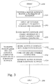
- a method for manufacturing a printed product comprises providing of a matrix comprising a matrix surface having at least one recess.
- a first curable compound is applied to the matrix surface and the recess(es) in a controlled amount that does not exceed a volume of said recess(es).
- the first curable compound creep down in and partly fill the recesses, leaving protruding surfaces substantially free from the first curable compound.
- the matrix surface and the at least one recess partially filled with the first curable compound is covered by a pickup layer of a second curable compound.
- the matrix is brought in contact with the substrate surface and the first curable compound and the second curable compound are cured, at least partly.
- the matrix surface is separated from the substrate surface, leaving the first curable compound on the substrate surface.
- the pickup layer and the first curable compound filling the at least one recess are thereby transferred together from the matrix surface onto a substrate surface of a substrate sheet.
- the first curable compound thus forms printed product micro features at the pickup layer covering the substrate surface.
- the second applicator separate from the first applicator, is arranged for covering the circumferential surface and the at least one recess filled with the first curable compound by a pickup layer of a second curable compound.
- the drive unit is arranged for rotating the matrix roll in a rotational direction.
- the substrate guides are arranged for bringing a substrate sheet in contact with the matrix roll in a contact section.
- the contact section is situated, in the rotational direction, after the second applicator.
- the first curable compound forms printed product micro features at the pickup layer covering the substrate surface.
- the curing means are arranged for curing the first curable compound and the second curable compound.
- the curing means is arranged to perform the curing at least to a part in the contact section.
- a product manufactured according to the present teachings comprises a body that in the product, or in an intermediate product, constitutes a substrate sheet with a limited thickness in relation to the extension in orthogonal directions thereof.
- the product has printed product micro features arranged on, or in, one or both principal surfaces of the substrate sheet.
- one embodiment of said product may comprise primary product micro features on a first side of a substrate sheet and secondary product micro features on the opposed side of the substrate sheet.
- the primary product micro features are typically locationally associated with the secondary product micro features.
- Other embodiments of said product may comprise three or more sets of product micro features. In its most basic form the product comprises a substrate sheet with product micro features printed on only one surface thereof.
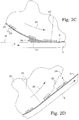
- Fig 1 shows a product 1 manufactured in accordance with one embodiment of the present teaching comprising an array of micro lenses 2 and an associated array of image objects 4 respectively arranged on opposite sides of a transparent substrate sheet 5.
- the aspects of the present disclosure are mainly described in terms of manufacturing of such a product arrangement.
- the present teachings are not limited to only this type of product but are applicable to various kinds of products having printed product micro features.
- the image objects 4 are printed on one or more pickup layers 6 (one such layer is shown, indicated by a first dotted line) arranged on the substrate sheet 5, without pre-structuring the substrate sheet 5.
- the micro lenses 2 may have been formed by embossing in the substrate sheet or by a cast cure process in a separate layer 7 (indicated by a second dotted line) on the substrate sheet 5.
- a separate layer 7 indicated by a second dotted line
- embodiments of the invention are exemplified with micro lenses it should be appreciated that other elements capable of focusing at a section of, and/or restricting the view of, an associated image object can be used to obtain an integral representation.
- Examples of other such focusing elements, besides micro lenses are micro mirrors, apertures, lenticular mirrors and lenticular lenses.
- the image objects 4 are thus in this present embodiment to be considered as printed product micro features 3 at a pickup layer 6 covering the substrate surface 10.
- spherical micro lenses are used as demonstration examples.
- micro lenses 2 can be manufactured in a similar manner, and in such a view, the micro lenses 2 are to be considered as printed product micro features 3 at a pickup layer covering the substrate surface 10.
- matrix is used to denote a body having a surface presenting a pattern of recesses or holes.
- the surface between these recesses is essentially flat or is following a smooth general shape, e.g. a cylinder shape.
- matrix roll is analogously interpreted as a roll having an outer or circumferential surface exhibiting a pattern of recesses or holes. The surface between these recesses follows a smooth general cylinder shape.
- the pattern of recesses corresponds to the structures that are intended to be printed onto a substrate.
- a first applicator 15 is arranged to interact with a matrix roll 20.
- the matrix roll 20 has a circumferential surface 24 with recesses 22.
- the first applicator 20 is arranged for application of a first curable compound 12 onto the matrix roll 20 so as to fill the recesses 22 with the first curable compound 12. Excess volumes of first curable compound 12 may in some embodiments appear e.g. on the circumferential surface, but may easily be removed, as discussed more in detail further below.
- the first curable compound 12 is provided from a first source 16 onto an application roll 14 of the first applicator 15.
- the matrix roll 20 rotates in a rotational direction 26 and the application roll 14 is arranged in rolling contact with the circumferential surface 24 of the matrix roll 20 and rotates therefore in an opposite direction.
- the interaction between the first applicator 15 and the matrix roll 20 results in a transfer of the first curable compound 12 into the recesses 22.
- the recesses are filled with fillings 28 of the first curable compound 12 when leaving the first applicator 15.
- the first applicator 15 can be composed of other parts, e.g. different kinds of spray arrangements, pouring conducts, scraping edges, slot dies etc.
- the integrity of the fillings 28 becomes relatively insensitive to e.g. printing speed. Furthermore, the need for pre-curing the fillings 28 is reduced, which also facilitates a subsequent removal of the fillings 28 from the recesses 22.
- Figs 2A-D are intended to show the principles in a very schematic manner and there may in different real embodiments be various additional steps, devices or alternative designs.
- the first curable compound is preferably at least partly cured at some stage of the processing of the product, e.g. before the contacting with the substrates.
- the first curable compound can be of a wide range of materials and hence curing may be accomplished by different mechanisms. Normally the term curing is associated with polymerisation of polymer materials initiated by irradiation, such as irradiation with ultraviolet (UV) light, and/or heating. Infrared irradiation, electron beam irradiation and the addition of chemical additives are other examples of means for curing.
- the first curable compound may comprise non-curable constituents as well.
- the term curing also includes drying.
- inks may be used for the curable compound.
- inks with dyes are used. Pigments may cause problems when printing small product micro features since the size of pigments particles usually is too large, which may adversely affect the resolution and colour density of the printed product micro features.
- any excess of the first curable compound in areas of the matrix surface of the matrix outside the recesses is removed such that the first curable compound of the product micro features eventually transferred to the substrate sheet substantially originates from the recesses.
- a squeegee, a clean rubber roll or the like can be used to wipe off any excessive curable compound from the matrix surface.
- Excessive first curable compound can also be removed by polishing. Different means for removal of excessive first curable compound can also be combined. In other words, under such conditions, it is preferable to introduce a process step, in which excessive first curable compound is removed from matrix surface outside the recesses before the covering by a pickup layer.
- the first curable compound initially has a low viscosity in order to enable the filling of small recesses of the matrix.
- This low viscosity is in a preferred embodiment typically between 100 and 600 mPas.
- the first curable compound may be removed from the recesses, in particular recesses having a comparatively large open surface as compared to the depth thereof, due to capillary forces acting on the low-viscosity curable compound.
- a higher viscosity of the first curable compound is desired while removing excessive first curable compound.
- a preferred embodiment of the manufacturing method comprises the step of increasing the viscosity of the first curable compound, e.g. by pre-curing, after filling of the recesses, i.e. the viscosity is lower during filling than e.g. during removal of excess first curable compound.
- the viscosity of the first curable compound is increased before a final removal such that the first curable compound behaves like a paste that is not significantly affected by capillary forces.
- An increase in the viscosity of the first curable compound applied to the matrix can be obtained by at least partly curing the first curable compound.
- the viscosity can also be controlled by other means such as by reducing the temperature of the first curable compound.
- a manufacturing process thus comprises the further step of pre-curing the first curable compound in the recesses before the covering of the matrix surface and the recesses filled with the first curable compound by a pickup layer is performed.
- a partially uncured first curable compound will typically have a higher adhesion to the pickup layer. Therefore, in most cases a fully cured first curable compound is not requested. In other words, in one embodiment, by leaving the curable compound partly uncured, the adhesion to the pickup layer will be improved in some cases.
- the duration of the contact between the first curable compound and the pickup layer is also important.
- the wet pickup layer will to some extent start to disintegrate or dissolve the surface of the partially cured first curable compound in the recesses. This dissolution contributes to a higher final adhesion between the first curable compound in the recesses and the pickup layer.
- the first curable compound in the recesses and the pickup layer subsequently are cured, such disintegration is again revoked, instead creating a strong bond between the two materials.
- a long contact time between the first curable compound in the recesses and the pickup layer before the common curing will increase the adhesion properties between the materials in the final product.
- the extent of curing of the first curable compound also has an effect on the ability to transfer the first curable compound in the recesses to the substrate sheet, i.e. the ability to withdraw the curable compound from the recesses.
- the extent of curing can be controlled before removal, but also the curable compound remaining in the recesses after removal of excessive curable compound and application of the pickup layer can be further cured prior to and/or during contact with the substrate sheet.
- the final curing is, at least to a part, performed during the step of transferring.
- the aspect ratio of the recesses typically increases.
- the amount of side walls in the matrix surface, directed in very different directions, increases and thereby the separation of the cured first curable compound from the recess becomes heavier.
- a product manufactured according to the above presented ideas may have one or more additional product micro features 3, e.g. lenses 2, provided in or on the substrate sheet 5 by embossing in the substrate sheet 5 or by applying a coating to the surface of the substrate sheet 5.
- Each additional product feature 3 being associated with a printed product feature 3 on the opposite side of the substrate sheet 5 may thereby form a focusing element 2 and an image object 4 pair for a synthetic image device.
- the product micro features 3 can be provided in any order, i.e. in the present embodiment first the lenses 2, followed by the image objects 4, or the image objects 4 followed by the lenses 2, or all product micro features 3 at the same time.
- more than one pick-up layers are provided on top of each other.
- the innermost pickup layer can be optimized for establishing a good adhesion to the curable compound in the recesses and may e.g. have a relatively high viscosity.
- an additional pickup layer may be provided, which e.g. has a lower viscosity for improving the wetting properties against the substrate.
- the pickup layer comprises a second curable material and is often referred to as a lacquer.
- the pickup layer 6 may also additionally comprise non-curable constituents.
- the application of the pickup layer may include the deposition of different primers or solvents, etching etc. in order to modify the surface properties of the first curable compound to obtain improved adhesion.
- Surface modification can also be applied on the outer surface of the pickup layer in order to modify the adhesion properties relative to the substrate.
- An increase in adhesion is typically accomplished by an increase of the surface energy of the pickup layer.
- the pickup layer may also in addition be pre-cured to some extent prior to contact with the substrate, and/or cured after being withdrawn from the matrix.
- Substrate guides 46, 48 are arranged for bringing a substrate sheet 5 in contact with the matrix roll 20 in a contact section 35.
- the contact section 35 is situated, in the rotational direction 26, after the second applicator 30.
- the pickup layer 6 and the first curable compound are transferred together from the circumferential surface 22 and left on a surface 10 of the substrate sheet 5.
- the arrangement 99 further comprises curing means 50.
- the curing means 50 is arranged for curing the first curable compound and the second curable compound.
- the curing means 50 is arranged to perform the curing at least to a part within the contact section 35. A final curing can also be performed after the contact section 35 is left.
- the matrix that is designed as the mould for the product micro features is thus preferably provided on a roll and at least the transferring of the first curable compound and the pickup layer is performed in a roll-to-roll process wherein at least the printed product micro features are continuously formed on the substrate sheet that is brought into rolling contact with the matrix roll.
- the substrate sheet 5 is provided and fed between the pressure roll 46 and the matrix roll 20 and then between the peeling roll 48 and the matrix roll 20, whereby the substrate sheet 5 is brought into rolling contact with the matrix roll 20 around a section of the matrix roll 20.
- a first curable compound is applied to the matrix roll 20 whereby the recesses 22 in the circumferential surface 24 of the matrix roll 20 are at least partly filled with the first curable compound.
- the viscosity of the first curable compound is adapted to enable it to fill the smallest recesses.
- the removal means 40 may in different particular embodiments comprise a squeegee and/or a polishing means.
- a polishing means is a fibre cloth arranged on a roll that is arranged to contact the matrix roll surface.
- Two or more removal means 40 can in certain embodiments be arranged in sequence to efficiently remove excessive first curable compound, e.g. a squeegee followed by a polishing means. Thereby the amount of excessive first curable compound left on intermediate surfaces can be minimised, which improves the polishing.
- pre-curing means 42 for increasing the viscosity of the first curable compound before removal of excessive first curable compound is arranged at least in-between the applicator 15 and the removal means 40. Since the pre-curing means 42 is not absolutely compulsory, it is illustrated by broken lines. Thus, the pre-curing means 42 is arranged for pre-curing the first curable compound in the recesses. The pre-curing means 42 is arranged to perform the pre-curing at least to a part before the removing of excessive first curable compound. The pre-curing means 42 is arranged, with respect to the rotational direction 26, before the second applicator 30.
- removal means may arranged at a position between the applicator 15 and the pre-curing means 42 to permit a coarse removal of excessive first curable compound.
- the viscosity of the first curable compound can first be optimised for filling of the first curable compound into the recesses 22 and then optimised by at least being partly cured to permit efficient removal of excessive first curable compound without removing the first curable compound from within the recesses 22.
- the first curable compound is at this step not necessarily fully cured, indeed it does not have to be cured at all when viscosity is increased by other means. Additional curing may be performed at subsequent steps.
- pre-curing means 44 may in addition be arranged in sequence with the applicator 30 at a position prior to where the matrix roll 20 is brought into rolling contact with the substrate sheet 5. At this position both the first and second curable compound can be cured, or further cured, if it has been partly cured before, but not necessarily fully cured.
- the substrate sheet 5 is brought into contact with the pickup layer 6 on the matrix roll 20 covering the first curable compound in the recesses 22 by means of the pressure roll 46.
- the pickup layer 6 adheres to the substrate sheet 5.
- the substrate sheet 5 is released from the circumferential surface 24 of the matrix roll 20 at the peeling roll 48 the first curable compound in the recesses 22 is peeled out from the recesses 22 and thereby transferred to the substrate sheet 5 to form the product micro features 3 on the pickup layer in turn on top of the substrate sheet 5.
- Curing means 50 is in one embodiment arranged at a position where the matrix roll 20 is in rolling contact with the substrate sheet 5. It can be used for additional curing, or, if no curing has been made previously, a first curing, of the first curable compound in the recesses 22 and the second curable compound in the pickup layer 6 before transfer of the first curable compound from the recesses 22 to the substrate sheet 5.
- the curing means 50 is arranged to perform the curing at least to a part in the contact section 35.
- means 99" for providing additional product micro features such as e.g. lenses 2, on the substrate sheet 5 on one side of the substrate sheet or both are provided.
- the means 99" for providing additional product micro features comprises another set of printing equipment analogue to the previous described one, where recesses corresponding to lenses 2 are provided in a matrix roll 20".
- a first applicator 15" provides a first curable compound into the recesses.
- a second applicator 30" provides a pickup layer on top of the lenses to be.
- a substrate sheet 5 is provided from a supply roll 60 and the lenses are printed onto the substrate surface 10.
- the means 99" for providing additional product micro features thus forms additional product micro features, e.g. in the form of micro lenses 2 on one side of the substrate sheet 5.
- the printed product is collected at a collection roll 66.
- An advantage by using a pickup layer also at the provision of the spherical micro lenses 2 is that it reduces the risk of encapsulating air volumes into the product, as is the case if the first curable compound is contacted directly to the substrate surface or on a substrate surface provided with a covering wetting layer.
- the means for providing additional product micro features may comprise means based on different techniques and process types such as, different types of printing, embossing, continuous casting, surface coating, laminating, or combinations thereof.
- printing techniques comprise screen printing, offset printing, flexographic printing, ink-jet printing and of course printing in accordance with the method of the present invention.
- the substrate sheet is at least in the areas that contribute to generation of a synthetic integral image transparent or translucent. Other areas may be opaque or have reduced transparency. For some optical applications the transparency may be of uttermost importance, however, for other applications, reflecting layers are instead required.
- the substrate sheet may thus in different applications comprise paper, films or metal, such as aluminium.
- the matrix or matrix roll may in one embodiment involve a printing plate.
- a printing plate is preferable fabricated using micro fabrication methods such as photolithographic techniques or e-beam direct writing, which are well known in the field of microsystems technology and microelectronics. This enables very high resolution, i.e. better than 0.5pm.
- the used line width can in specific embodiments be at least down to 0.5 ⁇ m, due to the improved adhesion properties.
- Typical depths of the recesses can be in the order of 1-2 ⁇ m, giving aspect ratios of 2-4. Resolution, depth of the recesses and aspect ratio is preferably designed from case to case.
- the master structure is a negative copy of the printing plate and can be used to manufacture numerous printing plates.
- the wear of the tool depends also to a high degree on the properties of the first curable compound. Corresponding wear resistant coatings could be lasting several times longer for one ink compared to another. For instance, white ink with abrasive TiO 2 as a first curable compound was found to cause a high wear.
- nitrogen can be added during the Ni plating step, thereby creating wear resistant nitride materials.
- the hardness of the Ni surface can be thus be improved.
- other additives, such as phosphorus can be used in this manner to improve the Ni surface hardness by nickel phosphides.
- the wetting layer also reduces the turbulence of material at the entrance of the contact section.
- the wetting layer is typically also a curable compound, which eventually is cured together with the second curable compound of the pickup layer and the first curable compound of the printed product micro features to be.
- the curable compound of the wetting layer may be the same as the first curable compound or the second curable compound or it may be another curable compound.
- the manufacturing method comprises the further step of providing the substrate with a wetting surface layer before bringing the matrix in contact with the substrate surface.
- a wetting layer is not exclusively usable with the embodiment of Fig. 5 , but can be combined with any other embodiments. Likewise, the main embodiment of Fig. 5 may be performed without the provision of a wetting layer.
- more than one arrangement 99 for continuous production of a printed product can also be provided on one and the same side of the substrate.
- Such an arrangement can thereby be used e.g. to print product micro features of different colours. It could also be useful when printing product micro features of so differing shapes or sizes that the use of two different matrixes is favourable.
- Such multiple printing units can be combined with any of the previous shown embodiments, for example, but not limited to the embodiments shown in Figs. 4 and 5 .
- supporting structures are provided in the recesses of the matrix in order to improve filling of large recesses by use of capillary forces.
- the distance between the supporting structures is adapted so that capillary forces can act on the curable compound filled into the recesses to enable complete filling of the recesses.
- the supporting structures are distributed in a disordered manner to reduce artefacts as if the supporting structures are arranged in an ordered array, small artefacts of the printed product micro features originating from the supporting structures may be perceived in normal use.
- the supporting structures are preferably positioned randomly or at least varied in such a way that they will not give rise to any moiré effect.
- the matrix comprises mainly "open” surfaces.
- the parts of the matrix that protrudes between the open areas have small line width, in a preferred embodiment typically below 5 ⁇ m.
- the line width may also be larger than that.
- the distance between the protruding parts cannot be too large, since the capillary forces attracting the ink towards the edges of the structures than may be too weak.
- a preferred embodiment has a distance between the structures that is typically not larger than typically 10 ⁇ m. If the distance in that example becomes much larger than that, the ink tends to stick to the edges, leaving the central part of the recess empty or at least partially empty from ink. A recessed surface of 20 ⁇ m therefore suffers from a lack of ink in the middle. If the recessed surface is further increased, the depleted zone comes at an approximate distance of 10-15 ⁇ m from the walls, whereas the central part of the recess has remaining ink.
- the maximum distance may also be different. The use randomly positioned support structures may also mitigate such effects.
- the patterns are preferably adapted to the differences in surface properties between ink and matrix.
- the capillary forces in the negative corners of the structures should typically exceed the surface tension that acts for keeping the ink at the surfaces of the protruding parts. In practice, the pattern cannot be allowed to involve too large flat protruding surfaces.
- the printing speed can be allowed to be high. Favourable tests have been made at different speed with essentially no difference in pattern quality. These test runs are performed without particularly adapting all parameters. By a proper selection of ink properties, pre-curing levels and pattern design, printing speeds of 100-150 cm/s are considered as perfectly feasible.
- the present disclose presents solutions for enabling high speed manufacturing of printed products.
- One contributing aspect is an increased adhesion between the print and the substrate. This in turn improves the possibilities to provide increased resolution and better contrast.
Landscapes
- Engineering & Computer Science (AREA)
- Mechanical Engineering (AREA)
- Physics & Mathematics (AREA)
- General Physics & Mathematics (AREA)
- Manufacturing & Machinery (AREA)
- Ophthalmology & Optometry (AREA)
- Health & Medical Sciences (AREA)
- Optics & Photonics (AREA)
- Printing Methods (AREA)
- Application Of Or Painting With Fluid Materials (AREA)
- Laminated Bodies (AREA)
- Printing Plates And Materials Therefor (AREA)
- Casting Or Compression Moulding Of Plastics Or The Like (AREA)
Applications Claiming Priority (3)
| Application Number | Priority Date | Filing Date | Title |
|---|---|---|---|
| SE1251247A SE537104C2 (sv) | 2012-11-02 | 2012-11-02 | Höghastighetstillverkning av tryckta produktmikrokännemärken |
| PCT/SE2013/051253 WO2014070079A1 (fr) | 2012-11-02 | 2013-10-25 | Procédé de fabrication de micro-traits de produit imprimé et agencement pour une production continue d'un tel produit |
| EP13851966.5A EP2914438B1 (fr) | 2012-11-02 | 2013-10-25 | Procédé de fabrication de micro-traits de produit imprimé et agencement pour une production continue d'un tel produit |
Related Parent Applications (2)
| Application Number | Title | Priority Date | Filing Date |
|---|---|---|---|
| EP13851966.5A Division EP2914438B1 (fr) | 2012-11-02 | 2013-10-25 | Procédé de fabrication de micro-traits de produit imprimé et agencement pour une production continue d'un tel produit |
| EP13851966.5A Division-Into EP2914438B1 (fr) | 2012-11-02 | 2013-10-25 | Procédé de fabrication de micro-traits de produit imprimé et agencement pour une production continue d'un tel produit |
Publications (3)
| Publication Number | Publication Date |
|---|---|
| EP3453537A1 true EP3453537A1 (fr) | 2019-03-13 |
| EP3453537B1 EP3453537B1 (fr) | 2023-11-22 |
| EP3453537C0 EP3453537C0 (fr) | 2023-11-22 |
Family
ID=50627808
Family Applications (2)
| Application Number | Title | Priority Date | Filing Date |
|---|---|---|---|
| EP18197417.1A Active EP3453537B1 (fr) | 2012-11-02 | 2013-10-25 | Fabrication à haute vitesse de microcaractéristiques du produit imprimé |
| EP13851966.5A Active EP2914438B1 (fr) | 2012-11-02 | 2013-10-25 | Procédé de fabrication de micro-traits de produit imprimé et agencement pour une production continue d'un tel produit |
Family Applications After (1)
| Application Number | Title | Priority Date | Filing Date |
|---|---|---|---|
| EP13851966.5A Active EP2914438B1 (fr) | 2012-11-02 | 2013-10-25 | Procédé de fabrication de micro-traits de produit imprimé et agencement pour une production continue d'un tel produit |
Country Status (8)
| Country | Link |
|---|---|
| US (2) | US9573353B2 (fr) |
| EP (2) | EP3453537B1 (fr) |
| CN (2) | CN105008138B (fr) |
| AU (2) | AU2013338691B2 (fr) |
| MX (1) | MX354168B (fr) |
| RU (2) | RU2637984C2 (fr) |
| SE (1) | SE537104C2 (fr) |
| WO (1) | WO2014070079A1 (fr) |
Families Citing this family (21)
| Publication number | Priority date | Publication date | Assignee | Title |
|---|---|---|---|---|
| JP6402625B2 (ja) * | 2013-03-28 | 2018-10-10 | 三菱ケミカル株式会社 | 光学フィルムの製造方法、光学フィルム、面発光体及び光学フィルムの製造装置 |
| DE102014012375A1 (de) * | 2014-08-20 | 2016-02-25 | Giesecke & Devrient Gmbh | Verfahren zum Herstellen eines optischen Elementes und optisches Element |
| MA42906A (fr) * | 2015-07-10 | 2018-05-16 | De La Rue Int Ltd | Procédé de fabrication d'un motif dans ou sur un support |
| GB201512120D0 (en) * | 2015-07-10 | 2015-08-19 | Rue De Int Ltd | A method for producing a pattern in or on a support |
| MA42899A (fr) * | 2015-07-10 | 2018-05-16 | De La Rue Int Ltd | Procédés de fabrication de documents de sécurité et de dispositifs de sécurité |
| GB2542834B (en) * | 2015-10-01 | 2017-10-04 | De La Rue Int Ltd | Method and apparatus for producing a printed product |
| GB2542847B (en) * | 2015-10-02 | 2019-12-04 | De La Rue Int Ltd | Methods of manufacturing a die form and applying a pattern to a support layer |
| GB2549780B (en) * | 2016-04-29 | 2019-11-27 | De La Rue Int Ltd | Methods of manufacturing lens transfer structures |
| GB201612290D0 (en) | 2016-07-15 | 2016-08-31 | La Rue Int De Ltd | Methods of manufacturing a secuirty device |
| CN107783208A (zh) * | 2016-08-25 | 2018-03-09 | 奇景光电股份有限公司 | 透明凸肋结构、复合光学棱镜与形成光学棱镜的方法 |
| GB2557167B (en) | 2016-09-30 | 2020-03-04 | De La Rue Int Ltd | Security devices |
| EP3366474B1 (fr) * | 2017-02-22 | 2020-06-24 | KBA-NotaSys SA | Presse à imprimer avec dispositif de coulée en ligne pour la réplication et la formation d'une structure micro-optique |
| FR3066142B1 (fr) | 2017-05-12 | 2022-03-11 | Ccl Secure Pty Ltd | Dispositif de securite optique et procede de fabrication |
| CN118810267A (zh) * | 2018-12-03 | 2024-10-22 | J·F·巴伯兰拉托雷 | 用于在基底上获得凸起图案的方法和装置 |
| GB2580069B (en) | 2018-12-20 | 2022-06-15 | De La Rue Int Ltd | Security documents and methods of manufacture thereof |
| GB202101267D0 (en) | 2021-01-29 | 2021-03-17 | De La Rue Int Ltd | Security devices and methods of manufacture thereof |
| CN113386454B (zh) * | 2021-05-28 | 2024-09-06 | 深圳劲嘉集团股份有限公司 | 一种彩色图文微纳结构印刷设备、印刷方法及印刷品 |
| WO2023177744A1 (fr) * | 2022-03-15 | 2023-09-21 | Nanografix Corporation | Système et procédé de génération d'images optiques holographiques dans un matériau durcissable |
| GB2621154B (en) | 2022-08-03 | 2024-12-18 | De La Rue Int Ltd | Security devices and methods of manufacture thereof |
| GB202300529D0 (en) | 2023-01-13 | 2023-03-01 | De La Rue Int Ltd | Security documents and methods for their manufacture |
| GB2627801A (en) | 2023-03-02 | 2024-09-04 | De La Rue Int Ltd | Security devices and methods of manufacture thereof |
Citations (2)
| Publication number | Priority date | Publication date | Assignee | Title |
|---|---|---|---|---|
| JPH0624198A (ja) * | 1992-07-08 | 1994-02-01 | Dainippon Printing Co Ltd | 立体感を有する化粧材 |
| WO2011102800A1 (fr) * | 2010-02-19 | 2011-08-25 | Rolling Optics Ab | Procédé pour imprimer des caractéristiques de produit sur une feuille de support |
Family Cites Families (8)
| Publication number | Priority date | Publication date | Assignee | Title |
|---|---|---|---|---|
| US6670096B2 (en) | 2000-12-01 | 2003-12-30 | Fuji Photo Film Co., Ltd. | Base material for lithographic printing plate and lithographic printing plate using the same |
| WO2005106601A2 (fr) * | 2004-04-30 | 2005-11-10 | De La Rue International Limited | Dispositifs optiquement variables ameliores |
| US20050276919A1 (en) * | 2004-06-01 | 2005-12-15 | Molecular Imprints, Inc. | Method for dispensing a fluid on a substrate |
| US7854823B2 (en) * | 2006-06-20 | 2010-12-21 | Snaper Alvin A | Synthesis of diamond by extraction of a pulse derived from the abrupt collapse of a magnetic field |
| DE102007025667A1 (de) * | 2007-06-01 | 2008-12-04 | Giesecke & Devrient Gmbh | Endlosmaterial für Sicherheitselemente |
| US20090145314A1 (en) * | 2007-12-07 | 2009-06-11 | Chemque, Inc. | Intaglio Printing Methods, Apparatuses, and Printed or Coated Materials Made Therewith |
| CN101221358A (zh) | 2008-02-04 | 2008-07-16 | 哈尔滨工业大学 | 基于柔性紫外压模的曲面基底多相位微光学元件加工方法 |
| WO2010117102A1 (fr) | 2009-04-09 | 2010-10-14 | 서강대학교 산학협력단 | Procede d'alignement de cristaux colloïdaux sous forme de monocristaux |
-
2012
- 2012-11-02 SE SE1251247A patent/SE537104C2/sv unknown
-
2013
- 2013-10-25 CN CN201380070461.XA patent/CN105008138B/zh active Active
- 2013-10-25 RU RU2015111986A patent/RU2637984C2/ru active
- 2013-10-25 RU RU2017141030A patent/RU2747162C2/ru active
- 2013-10-25 MX MX2015005447A patent/MX354168B/es active IP Right Grant
- 2013-10-25 WO PCT/SE2013/051253 patent/WO2014070079A1/fr active Application Filing
- 2013-10-25 EP EP18197417.1A patent/EP3453537B1/fr active Active
- 2013-10-25 US US14/440,303 patent/US9573353B2/en active Active
- 2013-10-25 EP EP13851966.5A patent/EP2914438B1/fr active Active
- 2013-10-25 AU AU2013338691A patent/AU2013338691B2/en active Active
- 2013-10-25 CN CN201611153871.2A patent/CN107089064B/zh active Active
-
2016
- 2016-07-07 US US15/204,877 patent/US9925750B2/en active Active
-
2017
- 2017-07-17 AU AU2017204911A patent/AU2017204911B2/en active Active
Patent Citations (2)
| Publication number | Priority date | Publication date | Assignee | Title |
|---|---|---|---|---|
| JPH0624198A (ja) * | 1992-07-08 | 1994-02-01 | Dainippon Printing Co Ltd | 立体感を有する化粧材 |
| WO2011102800A1 (fr) * | 2010-02-19 | 2011-08-25 | Rolling Optics Ab | Procédé pour imprimer des caractéristiques de produit sur une feuille de support |
Also Published As
| Publication number | Publication date |
|---|---|
| CN105008138B (zh) | 2016-11-16 |
| EP3453537B1 (fr) | 2023-11-22 |
| RU2747162C2 (ru) | 2021-04-28 |
| AU2017204911A1 (en) | 2017-08-03 |
| SE1251247A1 (sv) | 2014-05-03 |
| US20160318324A1 (en) | 2016-11-03 |
| CN107089064A (zh) | 2017-08-25 |
| US9925750B2 (en) | 2018-03-27 |
| CN105008138A (zh) | 2015-10-28 |
| RU2015111986A (ru) | 2016-12-27 |
| EP2914438B1 (fr) | 2018-12-19 |
| AU2017204911B2 (en) | 2018-05-24 |
| RU2017141030A3 (fr) | 2021-03-09 |
| AU2013338691A1 (en) | 2015-05-07 |
| MX354168B (es) | 2018-02-16 |
| US20150360453A1 (en) | 2015-12-17 |
| US9573353B2 (en) | 2017-02-21 |
| MX2015005447A (es) | 2015-09-24 |
| CN107089064B (zh) | 2020-03-17 |
| WO2014070079A1 (fr) | 2014-05-08 |
| RU2017141030A (ru) | 2019-02-12 |
| EP3453537C0 (fr) | 2023-11-22 |
| AU2013338691B2 (en) | 2017-04-20 |
| SE537104C2 (sv) | 2015-01-07 |
| EP2914438A4 (fr) | 2016-12-21 |
| RU2637984C2 (ru) | 2017-12-08 |
| EP2914438A1 (fr) | 2015-09-09 |
Similar Documents
| Publication | Publication Date | Title |
|---|---|---|
| AU2017204911B2 (en) | High-speed manufacturing of printed product micro features | |
| EP2536564B1 (fr) | Procédé pour imprimer des caractéristiques de produit sur une feuille de support | |
| EP1919711B1 (fr) | Procédé d impression | |
| EP3049249B1 (fr) | Procédé pour la fabrication d'un motif sur une bande de substrat et appareil associé | |
| JP5340220B2 (ja) | エンボスインキ、部分マットハードコート転写シートと部分マットハードコート成形品の製造方法 | |
| EP3745211A1 (fr) | Procédés d'application d'un matériau de transfert sur une surface de substrat | |
| TW202332568A (zh) | 壓印方法 |
Legal Events
| Date | Code | Title | Description |
|---|---|---|---|
| PUAI | Public reference made under article 153(3) epc to a published international application that has entered the european phase |
Free format text: ORIGINAL CODE: 0009012 |
|
| STAA | Information on the status of an ep patent application or granted ep patent |
Free format text: STATUS: THE APPLICATION HAS BEEN PUBLISHED |
|
| AC | Divisional application: reference to earlier application |
Ref document number: 2914438 Country of ref document: EP Kind code of ref document: P |
|
| AK | Designated contracting states |
Kind code of ref document: A1 Designated state(s): AL AT BE BG CH CY CZ DE DK EE ES FI FR GB GR HR HU IE IS IT LI LT LU LV MC MK MT NL NO PL PT RO RS SE SI SK SM TR |
|
| STAA | Information on the status of an ep patent application or granted ep patent |
Free format text: STATUS: REQUEST FOR EXAMINATION WAS MADE |
|
| 17P | Request for examination filed |
Effective date: 20190913 |
|
| RBV | Designated contracting states (corrected) |
Designated state(s): AL AT BE BG CH CY CZ DE DK EE ES FI FR GB GR HR HU IE IS IT LI LT LU LV MC MK MT NL NO PL PT RO RS SE SI SK SM TR |
|
| STAA | Information on the status of an ep patent application or granted ep patent |
Free format text: STATUS: EXAMINATION IS IN PROGRESS |
|
| 17Q | First examination report despatched |
Effective date: 20210607 |
|
| STAA | Information on the status of an ep patent application or granted ep patent |
Free format text: STATUS: EXAMINATION IS IN PROGRESS |
|
| GRAP | Despatch of communication of intention to grant a patent |
Free format text: ORIGINAL CODE: EPIDOSNIGR1 |
|
| STAA | Information on the status of an ep patent application or granted ep patent |
Free format text: STATUS: GRANT OF PATENT IS INTENDED |
|
| RIC1 | Information provided on ipc code assigned before grant |
Ipc: G02B 3/00 20060101ALI20230629BHEP Ipc: B29D 11/00 20060101ALI20230629BHEP Ipc: G03F 7/00 20060101ALI20230629BHEP Ipc: B41F 9/00 20060101ALI20230629BHEP Ipc: B41M 1/10 20060101AFI20230629BHEP |
|
| INTG | Intention to grant announced |
Effective date: 20230726 |
|
| GRAS | Grant fee paid |
Free format text: ORIGINAL CODE: EPIDOSNIGR3 |
|
| GRAA | (expected) grant |
Free format text: ORIGINAL CODE: 0009210 |
|
| STAA | Information on the status of an ep patent application or granted ep patent |
Free format text: STATUS: THE PATENT HAS BEEN GRANTED |
|
| AC | Divisional application: reference to earlier application |
Ref document number: 2914438 Country of ref document: EP Kind code of ref document: P |
|
| AK | Designated contracting states |
Kind code of ref document: B1 Designated state(s): AL AT BE BG CH CY CZ DE DK EE ES FI FR GB GR HR HU IE IS IT LI LT LU LV MC MK MT NL NO PL PT RO RS SE SI SK SM TR |
|
| REG | Reference to a national code |
Ref country code: GB Ref legal event code: FG4D |
|
| REG | Reference to a national code |
Ref country code: CH Ref legal event code: EP Ref country code: DE Ref legal event code: R096 Ref document number: 602013084975 Country of ref document: DE |
|
| REG | Reference to a national code |
Ref country code: IE Ref legal event code: FG4D |
|
| U01 | Request for unitary effect filed |
Effective date: 20231124 |
|
| U07 | Unitary effect registered |
Designated state(s): AT BE BG DE DK EE FI FR IT LT LU LV MT NL PT SE SI Effective date: 20231130 |
|
| PG25 | Lapsed in a contracting state [announced via postgrant information from national office to epo] |
Ref country code: GR Free format text: LAPSE BECAUSE OF FAILURE TO SUBMIT A TRANSLATION OF THE DESCRIPTION OR TO PAY THE FEE WITHIN THE PRESCRIBED TIME-LIMIT Effective date: 20240223 |
|
| PG25 | Lapsed in a contracting state [announced via postgrant information from national office to epo] |
Ref country code: IS Free format text: LAPSE BECAUSE OF FAILURE TO SUBMIT A TRANSLATION OF THE DESCRIPTION OR TO PAY THE FEE WITHIN THE PRESCRIBED TIME-LIMIT Effective date: 20240322 |
|
| PG25 | Lapsed in a contracting state [announced via postgrant information from national office to epo] |
Ref country code: ES Free format text: LAPSE BECAUSE OF FAILURE TO SUBMIT A TRANSLATION OF THE DESCRIPTION OR TO PAY THE FEE WITHIN THE PRESCRIBED TIME-LIMIT Effective date: 20231122 |
|
| PG25 | Lapsed in a contracting state [announced via postgrant information from national office to epo] |
Ref country code: IS Free format text: LAPSE BECAUSE OF FAILURE TO SUBMIT A TRANSLATION OF THE DESCRIPTION OR TO PAY THE FEE WITHIN THE PRESCRIBED TIME-LIMIT Effective date: 20240322 Ref country code: GR Free format text: LAPSE BECAUSE OF FAILURE TO SUBMIT A TRANSLATION OF THE DESCRIPTION OR TO PAY THE FEE WITHIN THE PRESCRIBED TIME-LIMIT Effective date: 20240223 Ref country code: ES Free format text: LAPSE BECAUSE OF FAILURE TO SUBMIT A TRANSLATION OF THE DESCRIPTION OR TO PAY THE FEE WITHIN THE PRESCRIBED TIME-LIMIT Effective date: 20231122 |
|
| PG25 | Lapsed in a contracting state [announced via postgrant information from national office to epo] |
Ref country code: RS Free format text: LAPSE BECAUSE OF FAILURE TO SUBMIT A TRANSLATION OF THE DESCRIPTION OR TO PAY THE FEE WITHIN THE PRESCRIBED TIME-LIMIT Effective date: 20231122 Ref country code: PL Free format text: LAPSE BECAUSE OF FAILURE TO SUBMIT A TRANSLATION OF THE DESCRIPTION OR TO PAY THE FEE WITHIN THE PRESCRIBED TIME-LIMIT Effective date: 20231122 Ref country code: NO Free format text: LAPSE BECAUSE OF FAILURE TO SUBMIT A TRANSLATION OF THE DESCRIPTION OR TO PAY THE FEE WITHIN THE PRESCRIBED TIME-LIMIT Effective date: 20240222 Ref country code: HR Free format text: LAPSE BECAUSE OF FAILURE TO SUBMIT A TRANSLATION OF THE DESCRIPTION OR TO PAY THE FEE WITHIN THE PRESCRIBED TIME-LIMIT Effective date: 20231122 |
|
| PG25 | Lapsed in a contracting state [announced via postgrant information from national office to epo] |
Ref country code: CZ Free format text: LAPSE BECAUSE OF FAILURE TO SUBMIT A TRANSLATION OF THE DESCRIPTION OR TO PAY THE FEE WITHIN THE PRESCRIBED TIME-LIMIT Effective date: 20231122 |
|
| PG25 | Lapsed in a contracting state [announced via postgrant information from national office to epo] |
Ref country code: SK Free format text: LAPSE BECAUSE OF FAILURE TO SUBMIT A TRANSLATION OF THE DESCRIPTION OR TO PAY THE FEE WITHIN THE PRESCRIBED TIME-LIMIT Effective date: 20231122 |
|
| PG25 | Lapsed in a contracting state [announced via postgrant information from national office to epo] |
Ref country code: SM Free format text: LAPSE BECAUSE OF FAILURE TO SUBMIT A TRANSLATION OF THE DESCRIPTION OR TO PAY THE FEE WITHIN THE PRESCRIBED TIME-LIMIT Effective date: 20231122 Ref country code: SK Free format text: LAPSE BECAUSE OF FAILURE TO SUBMIT A TRANSLATION OF THE DESCRIPTION OR TO PAY THE FEE WITHIN THE PRESCRIBED TIME-LIMIT Effective date: 20231122 Ref country code: RO Free format text: LAPSE BECAUSE OF FAILURE TO SUBMIT A TRANSLATION OF THE DESCRIPTION OR TO PAY THE FEE WITHIN THE PRESCRIBED TIME-LIMIT Effective date: 20231122 Ref country code: CZ Free format text: LAPSE BECAUSE OF FAILURE TO SUBMIT A TRANSLATION OF THE DESCRIPTION OR TO PAY THE FEE WITHIN THE PRESCRIBED TIME-LIMIT Effective date: 20231122 |
|
| REG | Reference to a national code |
Ref country code: DE Ref legal event code: R097 Ref document number: 602013084975 Country of ref document: DE |
|
| PLBE | No opposition filed within time limit |
Free format text: ORIGINAL CODE: 0009261 |
|
| STAA | Information on the status of an ep patent application or granted ep patent |
Free format text: STATUS: NO OPPOSITION FILED WITHIN TIME LIMIT |
|
| PGFP | Annual fee paid to national office [announced via postgrant information from national office to epo] |
Ref country code: GB Payment date: 20240913 Year of fee payment: 12 |
|
| U20 | Renewal fee paid [unitary effect] |
Year of fee payment: 12 Effective date: 20240918 |
|
| 26N | No opposition filed |
Effective date: 20240823 |
|
| PGFP | Annual fee paid to national office [announced via postgrant information from national office to epo] |
Ref country code: CH Payment date: 20241101 Year of fee payment: 12 |