EP3453292A1 - Kettle provided with at least two pouring rates - Google Patents
Kettle provided with at least two pouring rates Download PDFInfo
- Publication number
- EP3453292A1 EP3453292A1 EP18187149.2A EP18187149A EP3453292A1 EP 3453292 A1 EP3453292 A1 EP 3453292A1 EP 18187149 A EP18187149 A EP 18187149A EP 3453292 A1 EP3453292 A1 EP 3453292A1
- Authority
- EP
- European Patent Office
- Prior art keywords
- shutter
- kettle
- pouring
- openings
- opening
- Prior art date
- Legal status (The legal status is an assumption and is not a legal conclusion. Google has not performed a legal analysis and makes no representation as to the accuracy of the status listed.)
- Withdrawn
Links
Images

Classifications
-
- A—HUMAN NECESSITIES
- A47—FURNITURE; DOMESTIC ARTICLES OR APPLIANCES; COFFEE MILLS; SPICE MILLS; SUCTION CLEANERS IN GENERAL
- A47J—KITCHEN EQUIPMENT; COFFEE MILLS; SPICE MILLS; APPARATUS FOR MAKING BEVERAGES
- A47J27/00—Cooking-vessels
- A47J27/21—Water-boiling vessels, e.g. kettles
- A47J27/21008—Water-boiling vessels, e.g. kettles electrically heated
-
- A—HUMAN NECESSITIES
- A47—FURNITURE; DOMESTIC ARTICLES OR APPLIANCES; COFFEE MILLS; SPICE MILLS; SUCTION CLEANERS IN GENERAL
- A47J—KITCHEN EQUIPMENT; COFFEE MILLS; SPICE MILLS; APPARATUS FOR MAKING BEVERAGES
- A47J27/00—Cooking-vessels
- A47J27/21—Water-boiling vessels, e.g. kettles
- A47J27/21166—Constructional details or accessories
- A47J27/21175—Covers
-
- A—HUMAN NECESSITIES
- A47—FURNITURE; DOMESTIC ARTICLES OR APPLIANCES; COFFEE MILLS; SPICE MILLS; SUCTION CLEANERS IN GENERAL
- A47J—KITCHEN EQUIPMENT; COFFEE MILLS; SPICE MILLS; APPARATUS FOR MAKING BEVERAGES
- A47J27/00—Cooking-vessels
- A47J27/21—Water-boiling vessels, e.g. kettles
- A47J27/21166—Constructional details or accessories
- A47J27/21191—Pouring spouts
-
- A—HUMAN NECESSITIES
- A47—FURNITURE; DOMESTIC ARTICLES OR APPLIANCES; COFFEE MILLS; SPICE MILLS; SUCTION CLEANERS IN GENERAL
- A47J—KITCHEN EQUIPMENT; COFFEE MILLS; SPICE MILLS; APPARATUS FOR MAKING BEVERAGES
- A47J41/00—Thermally-insulated vessels, e.g. flasks, jugs, jars
- A47J41/0005—Thermally-insulated vessels, e.g. flasks, jugs, jars comprising a single opening for filling and dispensing provided with a stopper
- A47J41/0016—Thermally-insulated vessels, e.g. flasks, jugs, jars comprising a single opening for filling and dispensing provided with a stopper the stopper remaining in the opening and clearing a passage way between stopper and vessel for dispensing
- A47J41/0022—Thermally-insulated vessels, e.g. flasks, jugs, jars comprising a single opening for filling and dispensing provided with a stopper the stopper remaining in the opening and clearing a passage way between stopper and vessel for dispensing the stopper comprising two or more pieces movable relatively to each other for opening or closing the dispensing passage
Definitions
- the present invention relates to a liquid heating apparatus, in particular an electric kettle, comprising an electric heating base, a body and a lid forming an enclosure intended to bring water to a boil, and more particularly a kettle whose pouring flow rate. is adjustable.
- a kettle comprising a body arranged above an electric heating bottom and a lid forming an enclosure for bringing water to a boil, the kettle comprising a water pouring duct and a shutter movable between a position closure of the pouring duct and at least one opening position of the pouring duct.
- the kettle has shutter actuating means which includes a push button. More or less pressing the button moves the shutter from the closed position to the open position through several intermediate positions in which the user can obtain several pouring rates.
- the intermediate positions of the shutter are not stable positions which allow a calibrated and repetitive pouring flow from one use to another.
- the user is encouraged to open the shutter in the maximum open position and manage the pouring rate by tilting more or less the kettle.
- An object of the present invention is to overcome the aforementioned drawbacks and to provide a kettle which has a simple and ergonomic implementation and safe use.
- Another object of the present invention is to provide a kettle which has a simple design and that is economical to implement.
- a kettle comprising a body arranged above an electric heating bottom and a lid forming an enclosure for bringing water to a boil, said kettle comprising a water pouring conduit and a device movable shutter between a closed position of the pouring duct and at least one opening position of the pouring duct, characterized in that a wall, comprising at least first and second through openings, is arranged transversely to the duct pouring and in that the closure device is movable between a closed position of the pouring conduit in which the closure device closes the first and second through openings, a first open position defining a first pouring rate in which the shutter device releases only the first through opening and a second open position defining a second th pouring rate in which the shutter device releases the first and second through openings.
- through opening there is a through opening or a group of through openings.
- the first through opening has a first passage section of the hot water which defines a first pouring rate when the closure device is in the first open position.
- the second through opening has a second section of the hot water passage which accumulated with the first passage section defines a second pouring rate when the closure device is in the second open position.
- the first flow will include a restricted flow which allows a high accuracy of pouring and the second flow will rather be a large flow that allows a rapid filling of a container.
- the ratio between the first section and the sum of the first and second sections is less than 0.3.
- the wall is arranged in the cover.
- This arrangement allows to position the flow management function in the lid, without complicating the body of the kettle.
- the wall is part of a bottom wall of the lid.
- the lid has a spout.
- the end of the pouring channel which is formed by the spout is also integrated in the lid.
- the shutter device comprises a shutter.
- one piece allows to close or release the first and second through openings.
- the shutter is movable in translation in a direction A.
- a translation is an easy movement to implement in the kettle, which simplifies its design.
- the shutter comprises a stud extending in the direction A and having a cross section identical to a section of the second through opening, the stud being adapted to slide in the second through opening between the closed position or the first position opening, wherein the stud is arranged in the second through opening, to the second open position, wherein the stud is translated outside the second through opening.
- the stud closes the second through opening and to pass into the second position defining the second pouring flow, the sliding block to release the second through opening.
- the shutter comprises a valve provided with a seal, the valve provided with the seal closing the first and second openings when the shutter is in the closed position.
- This arrangement makes it possible to obtain a tight closure of the kettle, especially in the event of a rollover.
- the kettle comprises a shutter control button, the control button being movable in rotation and having three stable positions.
- control button comprises a cam comprising two sectors of different slopes.
- the first and second through openings are cylindrical.
- Such a construction allows in particular an easy adjustment of the stud in the second through opening.
- a kettle 1 comprises a base 2 electrically powered by a cord (not shown in the figures) and a body 3 forming a receptacle for water.
- the body 3 comprises an upper filling opening 4 which is closed by a lid 10.
- the lid 10 comprises a spout 11 located at the top opening 4.
- the kettle 1 comprises a handle 5 located opposite the spout pourer 11 relative to the upper opening.
- the body 3 has a substantially cylindrical shape comprising a vertical axis 70.
- the cover 10 is removable relative to the body 3 and the cover 10 is intended to be assembled sealingly on the body 3 in a translational movement substantially parallel to the vertical axis 70 of the body 3.
- the body 3 comprises a heating base formed of a stainless steel cup in which are arranged an aluminum diffuser and a heating element (not shown in the figures).
- the body 3 provided with the heating bottom and the lid 10 forms an enclosure for carrying water to a boil.
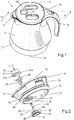
- the lid 10 comprises a lower housing 12, an intermediate portion 13 and an upper housing 14.
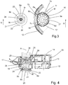
- the lid 10 comprises a pouring duct 15 of the hot water ( Fig.4 ) and the spout 11 forms an outlet end of the pouring duct 15.
- the pouring duct 15 comprises a wall 16 provided with 6 first through openings 6a, 6b, 6c, 6d, 6e, 6f and 18 second through openings 7a , 7b, 7c, ..., 7r through which hot water can pass ( Fig.3 ).
- the first 6 through openings 6a, 6b, 6c, 6d, 6e, 6f and the second through openings 7a, 7b, 7c, ..., 7r are identical and cylindrical.
- the wall 16 is substantially horizontal and is part of a bottom wall 17 of the lower housing 12.
- the wall 16 forms an inlet end of the pouring duct 15.
- On the figure 4 an arrow illustrates the path followed by the hot water in the pouring duct 15.
- the lid 10 comprises a closure device comprising a shutter 20 movable in translation along a direction A, parallel to the vertical axis 70 and perpendicular to a horizontal plane in which the wall 16 extends.
- the shutter 20 comprises a valve 21 arranged under the wall 16.
- the valve 21 takes the form of a disk and comprises a peripheral seal 22 intended to cooperate with the wall 16.
- the valve 21 comprises an upper face 23 from which extend 18 studs 8a, 8b, 8c ..., 8r according to the direction A ( Fig.3 ).
- Each stud 8a, ..., 8r is intended to cooperate with a second through opening 7a, ..., 7r.
- Each stud 8a, ..., 8r is cylindrical and has a cross section identical to a section of each of the second through openings 7a, ..., 7r.
- the shutter 20 is movable between a closed position of the pouring duct 15 in which the valve 21 provided with the seal 22 closes the first 6 through openings 6a, ..., 6f and 18 second through openings 7a,. .., 7r ( Fig.4 ) and two opening positions ( Fig.5 and 6 ).
- a first open position defines a first pouring flow in which the 18 studs 8a, ..., 8r close the second through openings 7a, ..., 7r, the shutter 20 releasing only the first 6 through openings 6a, ..., 6f.
- the first pouring rate is defined by the sum of the sections of the 6 through openings 6a, ..., 6f released by the shutter.
- This group of 6 through openings 6a, ..., 6f is equivalent to a first through opening.
- a dotted arrow illustrates the path followed by the hot water in the pouring duct 15.
- a second open position defines a second pouring rate in which the shutter releases the second through openings 7a, ..., 7r in addition to the first 6 through openings already released in the first open position.
- the group of 18 second through openings 7a, ..., 7r is equivalent to a second through opening.
- the second pouring rate is defined by the sum of the sections of the first 6 through openings 6a, ..., 6f and 18 second through openings 7a, ..., 7r released by the shutter.
- the large number of first 6 through openings 6a, ..., 6f and second through openings 7a, ..., 7r makes it possible to limit the speed of the hot water flow in the pouring conduit 15, both in the first open position than in the second open position.
- a dotted arrow illustrates the path followed by the hot water in the pouring duct 15.
- Each stud 8a, ..., 8r is adapted to slide in the corresponding second through opening 7a, ..., 7r between the closed position or the first open position in which the stud 8a, ..., 8r is arranged in the second through opening 7a, ..., 7r towards the second open position in which the stud 8a, ..., 8r is translated outside the second through opening 7a, ..., 7r, towards the inside the kettle enclosure 1.
- the shutter 20 comprises a rod 24 extending from the upper face 23 of the valve 21 in the direction A.
- An actuator 25 is arranged on a free end of the rod 24.
- a guide element 26 ( Fig.4 ) arranged in the intermediate portion 13 of the cover 10, serves to guide the actuator 25 in translation in the direction A, and the rod 24, the valve 21 and the pads 8a, ..., 8r.
- the wall 16 also comprises a guide opening 27 in translation of the rod 24, the valve 21 and the pads 8a, ..., 8r.
- a control button 30 of the shutter 20 is arranged in the cover 10.
- the control button 30 is movable in rotation and has three stable positions: a central position, an upright position and a left position.
- the control button 30 comprises a cylindrical cam 31 ( Fig. 2 ) whose profile comprises two sectors 31a, 31b of different slopes.
- the cam 31 cooperates with a pusher 28 secured to the actuator 25.
- the sector 31a having the lowest slope cooperates with the pusher 28 to pass the shutter 20 in its first open position.
- the sector 31b with the largest slope cooperates with the pusher 28 to pass the shutter 20 in its second open position.
- the sectors 31a, 31b are arranged head to tail.
- the central position of the control button 31 corresponds to the closing position of the shutter 20.
- a clockwise rotation of the control knob 30 moves it to its right position and causes the shutter 20 to go into its first position. opening position while a rotation in the anti direction time of the control button 30 moves it to its left position and passes the shutter 20 in its second open position.
- a return spring 29 ( Fig.4 ) is arranged between the guiding element 26 and the actuator 25 to bring the pusher 28 into contact with the cam 31.
- the shutter 20 In operation, when the control knob 30 is in the central position, the shutter 20 is in its closed position of the pouring duct 15 and the first 6 through-openings 6a, ..., 6f and the second through-openings 7a, ..., 7r are closed.
- the user who wants to pour the hot water with a reduced flow turns the control knob 31 to the right position to pass the shutter 20 in its first open position.
- the first open position defines a first reduced flow rate in which the valve 21 by translating releases the first 6 through openings 6a, ..., 6f.
- the 18 studs 8a, ..., 8r of the valve 21 translate into the second through openings 7a, ..., 7r and keep them closed.
- the user can then grasp the handle 5 of the kettle 1 and pour hot water into a container with a reduced flow rate.
- the user who wants to pour the hot water with a high flow turns the control knob 30 to the left position to pass the shutter 20 in its second open position.
- the second open position defines a second large pouring flow in which the 18 studs 8a, ..., 8r of the valve 21 translate outside the second through openings 7a, ..., 7r to release them in addition to the 6 first through openings 6a, ..., 6f already released in the first open position.
- the user can then grab the handle 5 of the kettle 1 and pour hot water into a container with a high flow rate.
- the shutter is movable in translation in a direction parallel to an extension plane of the wall having the first and second through openings.
- the closure device comprises a first shutter that closes or releases the first through opening and a second shutter that closes or releases the second through opening.
- the wall comprises, in addition to first and second through openings, a third through opening.
- the movable shutter device has a third open position defining a third pouring rate in which the shutter device releases the first, second and third through openings.
- the closure device may comprise a shutter provided with a second stud which cooperates with the third through opening, the second stud being longer than the stud cooperating with the second through opening.
- the control button may comprise a cam comprising a third sector of slope different from the first two.
Abstract
L'invention concerne une bouilloire (1) comprenant un corps (3) agencé au-dessus d'un fond chauffant électrique et un couvercle (10) formant une enceinte destinée à porter de l'eau à ébullition, ladite bouilloire (1) comprenant un conduit de versage (15) de l'eau et un obturateur (20) mobile entre une position de fermeture du conduit de versage (15) et au moins une position d'ouverture du conduit de versage (15). Conformément à l'invention, une paroi (16), comportant au moins des première (6a, ..., 6f) et deuxième ouvertures traversantes (7a, ...,7r), est agencée transversalement au conduit de versage (15) et en ce que l'obturateur (20) est mobile entre une position de fermeture du conduit de versage (15) dans laquelle l'obturateur (20) ferme les première (6a, ..., 6f) et deuxième ouvertures traversantes (7a, ...,7r), une première position d'ouverture définissant un premier débit de versage dans laquelle l'obturateur (20) libère uniquement la première ouverture traversante (6a, ..., 6f) et une deuxième position d'ouverture définissant un deuxième débit de versage dans laquelle l'obturateur (20) libère les première (6a, ..., 6f) et deuxième ouvertures traversantes (7a, ...,7r).The invention relates to a kettle (1) comprising a body (3) arranged above an electric heating bottom and a lid (10) forming an enclosure for bringing water to a boil, said kettle (1) comprising a pouring duct (15) of water and a shutter (20) movable between a closed position of the pouring duct (15) and at least one opening position of the pouring duct (15). According to the invention, a wall (16), comprising at least first (6a, ..., 6f) and second through openings (7a, ..., 7r), is arranged transversely to the pouring duct (15) and in that the shutter (20) is movable between a closed position of the pouring duct (15) in which the shutter (20) closes the first (6a, ..., 6f) and second through openings (7a). , ..., 7r), a first open position defining a first pouring rate in which the shutter (20) releases only the first through opening (6a, ..., 6f) and a second open position defining a second pouring flow in which the shutter (20) releases the first (6a, ..., 6f) and second through openings (7a, ..., 7r).
Description
La présente invention concerne un appareil de chauffage de liquides, notamment une bouilloire électrique, comportant un fond chauffant électrique, un corps et un couvercle formant une enceinte destinée à porter de l'eau à ébullition, et plus particulièrement une bouilloire dont le débit de versage est ajustable.The present invention relates to a liquid heating apparatus, in particular an electric kettle, comprising an electric heating base, a body and a lid forming an enclosure intended to bring water to a boil, and more particularly a kettle whose pouring flow rate. is adjustable.
On connait par exemple du document
Cependant, les positions intermédiaires de l'obturateur ne sont pas des positions stables qui permettent d'avoir un débit de versage calibré et répétitif d'une utilisation à l'autre. Ainsi, l'utilisateur est incité à ouvrir l'obturateur en position d'ouverture maximum et de gérer le débit de versage en inclinant plus ou moins la bouilloire.However, the intermediate positions of the shutter are not stable positions which allow a calibrated and repetitive pouring flow from one use to another. Thus, the user is encouraged to open the shutter in the maximum open position and manage the pouring rate by tilting more or less the kettle.
De plus, pour verser de l'eau, il faut maintenir une pression constante sur le bouton pour déplacer l'obturateur dans une position d'ouverture.In addition, to pour water, it is necessary to maintain a constant pressure on the button to move the shutter in an open position.
Un but de la présente invention est de remédier aux inconvénients précités et de proposer une bouilloire qui présente une mise en oeuvre simple et ergonomique et une utilisation sûre.An object of the present invention is to overcome the aforementioned drawbacks and to provide a kettle which has a simple and ergonomic implementation and safe use.
Un autre but de la présente invention est de proposer une bouilloire qui présente une conception simple et qui soit économique à mettre en oeuvre.Another object of the present invention is to provide a kettle which has a simple design and that is economical to implement.
Ces buts sont atteints avec une bouilloire comprenant un corps agencé au-dessus d'un fond chauffant électrique et un couvercle formant une enceinte destinée à porter de l'eau à ébullition, ladite bouilloire comprenant un conduit de versage de l'eau et un dispositif d'obturation mobile entre une position de fermeture du conduit de versage et au moins une position d'ouverture du conduit de versage, caractérisée en ce qu'une paroi, comportant au moins des première et deuxième ouvertures traversantes, est agencée transversalement au conduit de versage et en ce que le dispositif d'obturation est mobile entre une position de fermeture du conduit de versage dans laquelle le dispositif d'obturation ferme les première et deuxième ouvertures traversantes, une première position d'ouverture définissant un premier débit de versage dans laquelle le dispositif d'obturation libère uniquement la première ouverture traversante et une deuxième position d'ouverture définissant un deuxième débit de versage dans laquelle le dispositif d'obturation libère les première et deuxième ouvertures traversantes.These objects are achieved with a kettle comprising a body arranged above an electric heating bottom and a lid forming an enclosure for bringing water to a boil, said kettle comprising a water pouring conduit and a device movable shutter between a closed position of the pouring duct and at least one opening position of the pouring duct, characterized in that a wall, comprising at least first and second through openings, is arranged transversely to the duct pouring and in that the closure device is movable between a closed position of the pouring conduit in which the closure device closes the first and second through openings, a first open position defining a first pouring rate in which the shutter device releases only the first through opening and a second open position defining a second th pouring rate in which the shutter device releases the first and second through openings.
Par une paroi est agencée transversalement au conduit de versage, on comprend que l'eau chaude versée hors de l'enceinte de la bouilloire passe uniquement par les au moins première et/ou deuxième ouvertures traversantes.By a wall is arranged transversely to the pouring conduit, it is understood that the hot water poured out of the enclosure of the kettle passes only through the at least first and / or second through openings.
Par ouverture traversante, on comprend une ouverture traversante ou un groupe d'ouvertures traversantes.By through opening, there is a through opening or a group of through openings.
La première ouverture traversante présente une première section de passage de l'eau chaude qui définit un premier débit de versage lorsque le dispositif d'obturation est dans la première position d'ouverture. La deuxième ouverture traversante présente une deuxième section de passage de l'eau chaude qui, cumulée avec la première section de passage définit un deuxième débit de versage lorsque le dispositif d'obturation est dans la deuxième position d'ouverture. Ainsi, seules les dispersions de fabrication sur les première et deuxième sections qui peuvent être facilement maitrisées lors de la production de la bouilloire influent sur la précision des premier et deuxième débits de versage. En conséquence, les première et deuxième sections sont parfaitement calibrées et définissent des premier et deuxième débits de versage précis et répétitifs dans le temps, notamment quel que soit le niveau de remplissage de la bouilloire.The first through opening has a first passage section of the hot water which defines a first pouring rate when the closure device is in the first open position. The second through opening has a second section of the hot water passage which accumulated with the first passage section defines a second pouring rate when the closure device is in the second open position. Thus, only the manufacturing dispersions on the first and second sections that can be easily mastered during the production of the kettle affect the accuracy of the first and second flow rates. pouring. As a result, the first and second sections are perfectly calibrated and define first and second flow rates accurate and repetitive over time, especially regardless of the filling level of the kettle.
Le premier débit sera notamment un débit restreint qui permet une grande précision de versage et le deuxième débit sera plutôt un débit important qui permet une grande rapidité de remplissage d'un récipient.The first flow will include a restricted flow which allows a high accuracy of pouring and the second flow will rather be a large flow that allows a rapid filling of a container.
De manière avantageuse, le rapport entre la première section et la somme des première et deuxième section est inférieur à 0,3.Advantageously, the ratio between the first section and the sum of the first and second sections is less than 0.3.
Avantageusement, la paroi est agencée dans le couvercle.Advantageously, the wall is arranged in the cover.
Cette disposition permet de positionner la fonction gestion du débit dans le couvercle, sans compliquer le corps de la bouilloire.This arrangement allows to position the flow management function in the lid, without complicating the body of the kettle.
De préférence, la paroi fait partie d'une paroi de fond du couvercle.Preferably, the wall is part of a bottom wall of the lid.
Avantageusement, le couvercle comporte un bec verseur.Advantageously, the lid has a spout.
Ainsi, l'extrémité du conduit de versage qui est formé par le bec verseur est également intégré au couvercle.Thus, the end of the pouring channel which is formed by the spout is also integrated in the lid.
De manière avantageuse, le dispositif d'obturation comporte un obturateur.Advantageously, the shutter device comprises a shutter.
Ainsi, une seule pièce permet de de fermer ou de libérer les première et deuxième ouvertures traversantes.Thus, one piece allows to close or release the first and second through openings.
De préférence, l'obturateur est mobile en translation selon une direction A.Preferably, the shutter is movable in translation in a direction A.
Une translation est un mouvement facile à mettre en oeuvre dans la bouilloire, ce qui permet de simplifier sa conception.A translation is an easy movement to implement in the kettle, which simplifies its design.
Avantageusement, l'obturateur comporte un plot s'étendant selon la direction A et présentant une section transversale identique à une section de la deuxième ouverture traversante, le plot étant adapté à coulisser dans la deuxième ouverture traversante entre la position de fermeture ou la première position d'ouverture, dans laquelle le plot est agencé dans la deuxième ouverture traversante, vers la deuxième position d'ouverture, dans laquelle le plot est translaté en dehors de la deuxième ouverture traversante.Advantageously, the shutter comprises a stud extending in the direction A and having a cross section identical to a section of the second through opening, the stud being adapted to slide in the second through opening between the closed position or the first position opening, wherein the stud is arranged in the second through opening, to the second open position, wherein the stud is translated outside the second through opening.
Ainsi, dans la position de fermeture ou dans la première position d'ouverture de l'obturateur définissant le premier débit de versage, le plot ferme la deuxième ouverture traversante et pour passer dans la deuxième position définissant le deuxième débit de versage, le plot coulisse pour libérer la deuxième ouverture traversante.Thus, in the closed position or in the first open position of the shutter defining the first pouring flow, the stud closes the second through opening and to pass into the second position defining the second pouring flow, the sliding block to release the second through opening.
De préférence, l'obturateur comporte un clapet muni d'un joint, le clapet muni du joint fermant les première et deuxième ouvertures lorsque l'obturateur est en position de fermeture.Preferably, the shutter comprises a valve provided with a seal, the valve provided with the seal closing the first and second openings when the shutter is in the closed position.
Cette disposition permet d'obtenir une fermeture étanche de la bouilloire, notamment en cas de renversement.This arrangement makes it possible to obtain a tight closure of the kettle, especially in the event of a rollover.
Avantageusement, la bouilloire comporte un bouton de commande de l'obturateur, le bouton de commande étant mobile en rotation et comportant trois positions stables.Advantageously, the kettle comprises a shutter control button, the control button being movable in rotation and having three stable positions.
Ainsi, une fois la position de l'obturateur définie par la position du bouton de commande, l'utilisateur n'a pas d'autre action à réaliser que de pencher la bouilloire pour verser l'eau chaude.Thus, once the position of the shutter defined by the position of the control button, the user has no other action to perform than to tip the kettle to pour the hot water.
De préférence, le bouton de commande comporte une came comprenant deux secteurs de pentes différentes.Preferably, the control button comprises a cam comprising two sectors of different slopes.
Ainsi, la rotation du secteur de la came avec la pente la plus faible agit sur l'obturateur pour le faire passer de sa position de fermeture vers sa première position de versage et la rotation du secteur de came avec la pente la plus importante agit sur l'obturateur pour le faire passer de sa position de fermeture vers sa deuxième position de versage.Thus, the rotation of the sector of the cam with the weakest slope acts on the shutter to move it from its closed position to its first pouring position and the rotation of the cam sector with the largest slope acts on the shutter to move it from its closed position to its second pouring position.
Avantageusement, les première et deuxième ouvertures traversantes sont cylindriques.Advantageously, the first and second through openings are cylindrical.
Une telle construction permet notamment un ajustage facile du plot dans la deuxième ouverture traversante.Such a construction allows in particular an easy adjustment of the stud in the second through opening.
L'invention sera mieux comprise à l'étude du mode de réalisation pris à titre nullement limitatif et illustré dans les figures annexées dans lesquelles :
- La
figure 1 illustre une vue en perspective d'une bouilloire selon un mode particulier de réalisation de l'invention. - La
figure 2 illustre une vue en perspective éclatée du couvercle et de l'obturateur de la bouilloire illustrée sur lafigure 1 . - La
figure 3 illustre une vue éclatée partielle du dessus selon la flèche III du boitier inférieur du couvercle illustré sur lafigure 2 , ainsi que de l'obturateur qui est déplacé latéralement au boitier inférieur. - La
figure 4 illustre une vue en coupe IV-IV du couvercle de la bouilloire illustrée sur lafigure 1 et également du couvercle illustré sur lafigure 3 , l'obturateur étant en position fermée. - La
figure 5 illustre une vue de face du couvercle de la bouilloire illustrée sur lafigure 1 , l'obturateur étant en première position de versage. - La
figure 6 illustre une vue de face du couvercle de la bouilloire illustrée sur lafigure 1 , l'obturateur étant en deuxième position de versage.
- The
figure 1 illustrates a perspective view of a kettle according to a particular embodiment of the invention. - The
figure 2 illustrates an exploded perspective view of the lid and the shutter of the kettle illustrated on thefigure 1 . - The
figure 3 illustrates a partial exploded view of the top according to the arrow III of the lower housing of the cover illustrated on thefigure 2 , as well as the shutter which is moved laterally to the lower housing. - The
figure 4 illustrates a sectional view IV-IV of the kettle lid illustrated on thefigure 1 and also the lid shown on thefigure 3 , the shutter being in the closed position. - The
figure 5 illustrates a front view of the kettle lid shown on thefigure 1 , the shutter being in the first pouring position. - The
figure 6 illustrates a front view of the kettle lid shown on thefigure 1 , the shutter being in the second pouring position.
On notera que, dans ce document, les termes «horizontal», «vertical», «inférieur», «supérieur», «haut», «bas», employés pour décrire la bouilloire, font référence à cette bouilloire en situation d'usage, lorsqu'elle est posée sur un plan de travail horizontal.Note that in this document, the terms "horizontal", "vertical", "lower", "upper", "high", "low", used to describe the kettle, refer to this kettle in use situation , when placed on a horizontal work surface.
Dans l'exemple de réalisation représenté aux
Le corps 3 comporte un fond chauffant formé d'une coupelle en acier inoxydable sous laquelle sont agencés un diffuseur en aluminium et un élément chauffant (non représentés sur les figures). Le corps 3 muni du fond chauffant et le couvercle 10 forme une enceinte destinée à porter de l'eau à ébullition.The
Tel que visible aux
Le couvercle 10 comporte un dispositif d'obturation comprenant un obturateur 20 mobile en translation le long d'une direction A, parallèle à l'axe vertical 70 et perpendiculaire à un plan horizontal dans lequel s'étend la paroi 16. L'obturateur 20 comporte un clapet 21 agencé sous la paroi 16. Le clapet 21 prend la forme d'un disque et comporte un joint d'étanchéité 22 périphérique destiné à coopérer avec la paroi 16. Le clapet 21 comprend une face supérieure 23 depuis laquelle s'étendent 18 plots 8a, 8b, 8c ..., 8r selon la direction A (
L'obturateur 20 est mobile entre une position de fermeture du conduit de versage 15 dans laquelle le clapet 21 muni du joint d'étanchéité 22 ferme les 6 premières ouvertures traversantes 6a, ..., 6f et les 18 deuxièmes ouvertures traversantes 7a, ..., 7r (
Une première position d'ouverture (
Une deuxième position d'ouverture (
Chaque plot 8a, ..., 8r est adapté à coulisser dans la deuxième ouverture traversante 7a, ..., 7r correspondante entre la position de fermeture ou la première position d'ouverture dans laquelle le plot 8a, ..., 8r est agencé dans la deuxième ouverture traversante 7a, ..., 7r vers la deuxième position d'ouverture dans laquelle le plot 8a, ..., 8r est translaté en dehors de la deuxième ouverture traversante 7a, ..., 7r, vers l'intérieur de l'enceinte de la bouilloire 1.Each
Conformément aux
Un bouton de commande 30 de l'obturateur 20 est agencé dans le couvercle 10. Le bouton de commande 30 est mobile en rotation et présente trois positions stables : une position centrale, une position droite et une position gauche. Le bouton de commande 30 comporte une came 31 cylindrique (
En fonctionnement, lorsque le bouton de commande 30 est en position centrale, l'obturateur 20 est dans sa position de fermeture du conduit de versage 15 et les 6 premières ouvertures traversantes 6a, ..., 6f et les 18 deuxièmes ouvertures traversantes 7a, ..., 7r sont fermées.In operation, when the
L'utilisateur qui veut verser l'eau chaude avec un débit réduit tourne le bouton de commande 31 vers la position droite pour faire passer l'obturateur 20 dans sa première position d'ouverture. La première position d'ouverture définit un premier débit de versage réduit dans laquelle le clapet 21 en translatant libère les 6 premières ouvertures traversantes 6a, ..., 6f. Les 18 plots 8a, ..., 8r du clapet 21 translatent dans les 18 deuxièmes ouvertures traversantes 7a, ..., 7r et les maintiennent fermées. L'utilisateur peut alors saisir la poignée 5 de la bouilloire 1 et verser de l'eau chaude dans un récipient avec un débit réduit.The user who wants to pour the hot water with a reduced flow turns the
L'utilisateur qui veut verser l'eau chaude avec un débit important tourne le bouton de commande 30 vers la position gauche pour faire passer l'obturateur 20 dans sa deuxième position d'ouverture. La deuxième position d'ouverture définit un deuxième débit de versage important dans laquelle les 18 plots 8a, ..., 8r du clapet 21 translatent en dehors des 18 deuxièmes ouvertures traversantes 7a, ..., 7r pour les libérer en plus des 6 premières ouvertures traversantes 6a, ..., 6f déjà libérées dans la première position d'ouverture. L'utilisateur peut alors saisir la poignée 5 de la bouilloire 1 et verser de l'eau chaude dans un récipient avec un débit important.The user who wants to pour the hot water with a high flow turns the
Bien entendu, l'invention n'est nullement limitée aux modes de réalisation décrits et illustrés qui n'ont été donnés qu'à titre d'exemple. Des modifications restent possibles, notamment du point de vue de la constitution des divers éléments ou par substitution d'équivalents techniques, sans sortir pour autant du domaine de protection de l'invention.Of course, the invention is not limited to the described and illustrated embodiments which have been given by way of example. Modifications are possible, particularly from the point of view of the constitution of the various elements or by substitution of technical equivalents, without leaving the domain of protection of the invention.
Dans une variante de réalisation non représentée, l'obturateur est mobile en translation selon une direction parallèle à un plan d'extension de la paroi comportant les première et deuxième ouvertures traversantes.In an alternative embodiment not shown, the shutter is movable in translation in a direction parallel to an extension plane of the wall having the first and second through openings.
Dans une première variante de réalisation, le dispositif d'obturation comporte un premier obturateur qui permet de fermer ou de libérer la première ouverture traversante et un deuxième obturateur qui permet de fermer ou de libérer la deuxième ouverture traversante.In a first embodiment, the closure device comprises a first shutter that closes or releases the first through opening and a second shutter that closes or releases the second through opening.
Dans une deuxième variante de réalisation, la paroi comporte, en plus des première et deuxième ouvertures traversantes, une troisième ouverture traversante. Le dispositif d'obturation mobile présente une troisième position d'ouverture définissant un troisième débit de versage dans laquelle le dispositif d'obturation libère les première, deuxième et troisième ouvertures traversantes. Le dispositif d'obturation peut comporter un obturateur muni d'un second plot qui coopère avec la troisième ouverture traversante, le second plot étant plus long que le plot coopérant avec la deuxième ouverture traversante. Le bouton de commande peut comporter une came comprenant un troisième secteur de pente différente des deux premières.In a second embodiment, the wall comprises, in addition to first and second through openings, a third through opening. The movable shutter device has a third open position defining a third pouring rate in which the shutter device releases the first, second and third through openings. The closure device may comprise a shutter provided with a second stud which cooperates with the third through opening, the second stud being longer than the stud cooperating with the second through opening. The control button may comprise a cam comprising a third sector of slope different from the first two.
Claims (11)
Applications Claiming Priority (1)
| Application Number | Priority Date | Filing Date | Title |
|---|---|---|---|
| FR1758274A FR3070586B1 (en) | 2017-09-07 | 2017-09-07 | KETTLE PROVIDED WITH AT LEAST TWO DEBITS OF VESSAGE |
Publications (1)
| Publication Number | Publication Date |
|---|---|
| EP3453292A1 true EP3453292A1 (en) | 2019-03-13 |
Family
ID=60450819
Family Applications (1)
| Application Number | Title | Priority Date | Filing Date |
|---|---|---|---|
| EP18187149.2A Withdrawn EP3453292A1 (en) | 2017-09-07 | 2018-08-02 | Kettle provided with at least two pouring rates |
Country Status (4)
| Country | Link |
|---|---|
| EP (1) | EP3453292A1 (en) |
| JP (1) | JP7222624B2 (en) |
| CN (1) | CN109464004B (en) |
| FR (1) | FR3070586B1 (en) |
Cited By (1)
| Publication number | Priority date | Publication date | Assignee | Title |
|---|---|---|---|---|
| FR3120184A1 (en) * | 2021-02-26 | 2022-09-02 | Seb S.A. | BEVERAGE MAKER WITH IMPROVED LID |
Families Citing this family (1)
| Publication number | Priority date | Publication date | Assignee | Title |
|---|---|---|---|---|
| JP6829282B2 (en) * | 2019-05-16 | 2021-02-10 | 象印マホービン株式会社 | Beverage dispenser |
Citations (5)
| Publication number | Priority date | Publication date | Assignee | Title |
|---|---|---|---|---|
| FR2756476A1 (en) * | 1996-12-04 | 1998-06-05 | Moulinex Sa | ELECTRIC KETTLE COMPRISING A CONTAINER WHICH IS OPENED BY A COVER |
| WO2001032063A1 (en) * | 1999-11-02 | 2001-05-10 | Seb Sa | Container with multiple-position closing device, in particular electric kettle |
| WO2005107539A1 (en) * | 2004-04-07 | 2005-11-17 | Seb S.A. | Electric liquid-heating appliance |
| CN201564130U (en) * | 2009-11-04 | 2010-09-01 | 广州市拓璞电器发展有限公司 | Spout structure |
| GB2471552A (en) * | 2009-06-26 | 2011-01-05 | Tsann Kuen | A kettle discharge attachment |
Family Cites Families (7)
| Publication number | Priority date | Publication date | Assignee | Title |
|---|---|---|---|---|
| JP3913227B2 (en) | 2004-03-29 | 2007-05-09 | サーモス株式会社 | Beverage container closure |
| GB2445026B (en) * | 2006-12-22 | 2011-08-10 | Salton Europ Ltd | Improvements in and relating to lids for domestic appliances |
| JP2009178413A (en) | 2008-01-31 | 2009-08-13 | Tiger Vacuum Bottle Co Ltd | Electric kettle |
| JP2013233225A (en) | 2012-05-07 | 2013-11-21 | Hitachi Living Supply:Kk | Electric kettle |
| FR3006875B1 (en) * | 2013-06-14 | 2015-06-05 | Seb Sa | KETTLE PROVIDED WITH A REMOVABLE DUST FILTER AND DUST CAP ASSEMBLY |
| FR3021198B1 (en) * | 2014-05-23 | 2016-05-13 | Seb Sa | DEVICE AND METHOD FOR PRODUCING AND DISPENSING BOILING LIQUID AND BEVERAGE PREPARING APPARATUS PROVIDED WITH SUCH A DEVICE |
| CN104997396A (en) * | 2015-07-13 | 2015-10-28 | 中山市美斯特实业有限公司 | Improved steam flow-adjustable electric kettle |
-
2017
- 2017-09-07 FR FR1758274A patent/FR3070586B1/en active Active
-
2018
- 2018-07-24 JP JP2018138277A patent/JP7222624B2/en active Active
- 2018-08-02 EP EP18187149.2A patent/EP3453292A1/en not_active Withdrawn
- 2018-09-07 CN CN201811042121.7A patent/CN109464004B/en active Active
Patent Citations (5)
| Publication number | Priority date | Publication date | Assignee | Title |
|---|---|---|---|---|
| FR2756476A1 (en) * | 1996-12-04 | 1998-06-05 | Moulinex Sa | ELECTRIC KETTLE COMPRISING A CONTAINER WHICH IS OPENED BY A COVER |
| WO2001032063A1 (en) * | 1999-11-02 | 2001-05-10 | Seb Sa | Container with multiple-position closing device, in particular electric kettle |
| WO2005107539A1 (en) * | 2004-04-07 | 2005-11-17 | Seb S.A. | Electric liquid-heating appliance |
| GB2471552A (en) * | 2009-06-26 | 2011-01-05 | Tsann Kuen | A kettle discharge attachment |
| CN201564130U (en) * | 2009-11-04 | 2010-09-01 | 广州市拓璞电器发展有限公司 | Spout structure |
Cited By (1)
| Publication number | Priority date | Publication date | Assignee | Title |
|---|---|---|---|---|
| FR3120184A1 (en) * | 2021-02-26 | 2022-09-02 | Seb S.A. | BEVERAGE MAKER WITH IMPROVED LID |
Also Published As
| Publication number | Publication date |
|---|---|
| CN109464004B (en) | 2021-04-09 |
| JP7222624B2 (en) | 2023-02-15 |
| FR3070586B1 (en) | 2019-08-30 |
| JP2019048040A (en) | 2019-03-28 |
| FR3070586A1 (en) | 2019-03-08 |
| CN109464004A (en) | 2019-03-15 |
Similar Documents
| Publication | Publication Date | Title |
|---|---|---|
| EP1032295B1 (en) | Device for locking/unlocking a pressure cooker with lug-bayonet type closure | |
| EP1734851B1 (en) | Electrical water heater | |
| EP1344476B1 (en) | Apparatus for cooking food under pressure with a rotative locking device | |
| EP1734849B1 (en) | Electric liquid-heating appliance | |
| FR2954073A1 (en) | ELECTRICAL FOOD COOKING APPARATUS | |
| WO2016193643A1 (en) | Valve for a pressurized cooking appliance, and pressurized cooking appliance provided with such a valve | |
| FR3070586B1 (en) | KETTLE PROVIDED WITH AT LEAST TWO DEBITS OF VESSAGE | |
| FR2993157A1 (en) | PRESSURIZED FOOD COOKING APPARATUS WITH IMPROVED CONTROL DEVICE | |
| EP2502530B1 (en) | Kettle comprising a lid provided with a retractable gripping element | |
| EP1734850B1 (en) | Electrical liquid-heating appliance | |
| EP1773161B1 (en) | Pourer container and brewing appliance comprising same | |
| EP3088599B1 (en) | Household ironing appliance comprising a steam generator provided with a discharge opening | |
| CH653546A5 (en) | ACCESSORY FOR DENTAL ART. | |
| FR2749745A1 (en) | COFFEE MACHINE OPERATING WITH DIFFERENT TYPES OF CONTAINERS | |
| EP1632600A1 (en) | Iron with a handle having a tank filling opening | |
| WO2007116153A2 (en) | Adjustable pressure cooking appliance with controlled decompression | |
| EP0426587A1 (en) | Mixing valve for sanitary installation | |
| EP2982278A1 (en) | Device for producing and fixing a food preparation | |
| EP3262993B1 (en) | Boiler provided with a pressure regulating device | |
| FR2756476A1 (en) | ELECTRIC KETTLE COMPRISING A CONTAINER WHICH IS OPENED BY A COVER | |
| FR2882625A1 (en) | Motorized hedge trimmer for shrubs, has rear part with fixed interposed handle and end handle, where end handle is inclined at specific angle relative to longitudinal axis, and control units of both handles move in direction normal to axis | |
| EP3533361A1 (en) | Container having a lid with pouring stopper with bistable control | |
| EP4306011A1 (en) | Kettle comprising a lid provided with a vapour discharge device | |
| WO2005082211A9 (en) | Domestic pressure food cooking device with improved guide for the locking means | |
| EP4298962A1 (en) | Kettle comprising a lid provided with a drain opening |
Legal Events
| Date | Code | Title | Description |
|---|---|---|---|
| PUAI | Public reference made under article 153(3) epc to a published international application that has entered the european phase |
Free format text: ORIGINAL CODE: 0009012 |
|
| AK | Designated contracting states |
Kind code of ref document: A1 Designated state(s): AL AT BE BG CH CY CZ DE DK EE ES FI FR GB GR HR HU IE IS IT LI LT LU LV MC MK MT NL NO PL PT RO RS SE SI SK SM TR |
|
| AX | Request for extension of the european patent |
Extension state: BA ME |
|
| 17P | Request for examination filed |
Effective date: 20190822 |
|
| RBV | Designated contracting states (corrected) |
Designated state(s): AL AT BE BG CH CY CZ DE DK EE ES FI FR GB GR HR HU IE IS IT LI LT LU LV MC MK MT NL NO PL PT RO RS SE SI SK SM TR |
|
| RIC1 | Information provided on ipc code assigned before grant |
Ipc: A47J 27/21 20060101AFI20191209BHEP Ipc: A47J 41/00 20060101ALI20191209BHEP |
|
| GRAP | Despatch of communication of intention to grant a patent |
Free format text: ORIGINAL CODE: EPIDOSNIGR1 |
|
| INTG | Intention to grant announced |
Effective date: 20200124 |
|
| STAA | Information on the status of an ep patent application or granted ep patent |
Free format text: STATUS: THE APPLICATION IS DEEMED TO BE WITHDRAWN |
|
| 18D | Application deemed to be withdrawn |
Effective date: 20200604 |