EP3453143B1 - Verfahren zur initialisierung eines bussystems und bussystem - Google Patents
Verfahren zur initialisierung eines bussystems und bussystem Download PDFInfo
- Publication number
- EP3453143B1 EP3453143B1 EP17703925.2A EP17703925A EP3453143B1 EP 3453143 B1 EP3453143 B1 EP 3453143B1 EP 17703925 A EP17703925 A EP 17703925A EP 3453143 B1 EP3453143 B1 EP 3453143B1
- Authority
- EP
- European Patent Office
- Prior art keywords
- bus
- master module
- bus subscriber
- subscriber
- bus system
- Prior art date
- Legal status (The legal status is an assumption and is not a legal conclusion. Google has not performed a legal analysis and makes no representation as to the accuracy of the status listed.)
- Active
Links
Images


Classifications
-
- H—ELECTRICITY
- H04—ELECTRIC COMMUNICATION TECHNIQUE
- H04L—TRANSMISSION OF DIGITAL INFORMATION, e.g. TELEGRAPHIC COMMUNICATION
- H04L12/00—Data switching networks
- H04L12/28—Data switching networks characterised by path configuration, e.g. LAN [Local Area Networks] or WAN [Wide Area Networks]
- H04L12/40—Bus networks
- H04L12/403—Bus networks with centralised control, e.g. polling
-
- H—ELECTRICITY
- H04—ELECTRIC COMMUNICATION TECHNIQUE
- H04L—TRANSMISSION OF DIGITAL INFORMATION, e.g. TELEGRAPHIC COMMUNICATION
- H04L12/00—Data switching networks
- H04L12/28—Data switching networks characterised by path configuration, e.g. LAN [Local Area Networks] or WAN [Wide Area Networks]
- H04L12/40—Bus networks
- H04L12/40006—Architecture of a communication node
- H04L12/40019—Details regarding a bus master
-
- H—ELECTRICITY
- H04—ELECTRIC COMMUNICATION TECHNIQUE
- H04L—TRANSMISSION OF DIGITAL INFORMATION, e.g. TELEGRAPHIC COMMUNICATION
- H04L41/00—Arrangements for maintenance, administration or management of data switching networks, e.g. of packet switching networks
- H04L41/06—Management of faults, events, alarms or notifications
- H04L41/0604—Management of faults, events, alarms or notifications using filtering, e.g. reduction of information by using priority, element types, position or time
- H04L41/0622—Management of faults, events, alarms or notifications using filtering, e.g. reduction of information by using priority, element types, position or time based on time
-
- H—ELECTRICITY
- H04—ELECTRIC COMMUNICATION TECHNIQUE
- H04L—TRANSMISSION OF DIGITAL INFORMATION, e.g. TELEGRAPHIC COMMUNICATION
- H04L41/00—Arrangements for maintenance, administration or management of data switching networks, e.g. of packet switching networks
- H04L41/06—Management of faults, events, alarms or notifications
- H04L41/0604—Management of faults, events, alarms or notifications using filtering, e.g. reduction of information by using priority, element types, position or time
- H04L41/0627—Management of faults, events, alarms or notifications using filtering, e.g. reduction of information by using priority, element types, position or time by acting on the notification or alarm source
-
- H—ELECTRICITY
- H04—ELECTRIC COMMUNICATION TECHNIQUE
- H04L—TRANSMISSION OF DIGITAL INFORMATION, e.g. TELEGRAPHIC COMMUNICATION
- H04L41/00—Arrangements for maintenance, administration or management of data switching networks, e.g. of packet switching networks
- H04L41/06—Management of faults, events, alarms or notifications
- H04L41/0631—Management of faults, events, alarms or notifications using root cause analysis; using analysis of correlation between notifications, alarms or events based on decision criteria, e.g. hierarchy, tree or time analysis
Definitions
- the invention relates to a method for initializing a bus system and a bus system.
- From the US 5 535 336 A is a network of bus subscribers with dynamic addressing known.
- the invention is therefore based on the object of developing a method for initializing a bus system and a bus system, wherein the security is improved.
- the object is achieved in the method for initializing a bus system according to the features specified in claim 1 and in the bus system according to the features specified in claim 6.
- the advantage here is that the bus system initializes itself by means of the method.
- the bus system detects which of the bus module is furthest from the master module and closes the bus system automatically.
- an operator of the bus system is relieved because he does not have to connect a terminating impedance within the system.
- the security is improved.
- the predetermined time periods are adaptable to the bus subscribers, so that they wait long enough for a bus subscriber, who requires a longer period of time to activate, to also be securely logged on.
- a fourth bus subscriber downstream of the first bus subscriber and / or second bus subscriber is sent an application to the master module after all predetermined time periods have expired, wherein in a sixth method step, the first bus subscriber or the second bus subscriber opens the bus system and forwards the registration of the fourth bus user to the master module.
- a release is granted to the bus system in a fifth method step, in particular by a higher-level control of the master module.
- the advantage here is that by means of the release the bus system receives an external release after successful initialization in an additional process step. Only after the release, the bus system goes into a production mode, in which the bus participants are controlled by the master module.
- a fourth bus subscriber downstream of the first bus subscriber and / or second bus subscriber sends an application to the master module after all predetermined time periods have elapsed, wherein in a seventh method step the first bus subscriber or the second bus subscriber logs on the fourth Bus participant blocked to the master module.
- the release of the bus system is withdrawn in an eighth method step, in particular by a master module higher-level control, wherein in a ninth step, the first bus or the second bus subscriber forwards the application of the fourth bus to the master module.
- the advantage here is that the fourth bus subscriber is automatically added to a restart of the bus system in the bus system.
- the fourth bus user waits a predetermined period of time, if a bus subscriber downstream of the fourth bus subscriber logs on to the master module, wherein in an eleventh method step the fourth bus subscriber closes the bus system, if within the specified time period does not register the bus node downstream of the fourth bus participant in the master module.
- the advantage here is that the assignment of the addresses to the bus participants takes place automatically. Thus, the commissioning of the bus system is safe and fast executable.
- a data packet passes during the addressing of an inactive bus subscriber, so that the next active bus subscriber of the bus system receives the address and thus logs on to the master module.
- the second bus subscriber increments the second address by one and assigns it to a third bus subscriber as a third address and sends this third address to the third Bus subscriber, in particular wherein the third address is the natural number (n + 2), wherein in a fifth method step, the third bus subscriber logs in with his third address at the master module. It is advantageous in this case that each bus subscriber, in particular each active bus subscriber, is automatically addressable by means of the method.
- the address m is assigned to an mth bus subscriber in a further method step, and the mth bus subscriber logs on to the master module with the address m, where m is a natural number, in particular where m is not equal to n, in particular where m is equal to 15, the mth bus user assigning the address m to a bus subscriber downstream of the mth bus subscriber and sending the address m to the downstream bus subscriber, in particular wherein the mth bus subscriber does not increment the address, wherein (m- 1) the maximum possible number of bus subscribers in the bus system.
- the advantage here is that the number of bus subscribers is limited. This prevents the data packets from becoming too long and improves the transmission speed.
- the number of bus subscribers is automatically limited.
- the master module aborts the method and sends an error message when a bus subscriber with the address m logs on to the master module.
- the advantage here is that the bus system automatically detects when too many bus subscribers log on.
- the error message is sent to a higher-level control.
- the master module generates a warning signal, in particular a warning tone or a warning light.
- the advantage here is that all bus users of the bus system can be switched off within a short time.
- the emergency signal is not fully evaluated, but, as soon as it was detected as an emergency signal, forwarded simultaneously to all bus users and the master module.
- the distress signal interrupts a data packet.
- the advantage here is that the distress signal is sent immediately to all bus users and the master module as soon as the error state has been detected.
- it is not necessary to wait until the data packet has been completely transmitted.
- the safety is improved.
- the transmission of the interrupted data packet is not continued and the interrupted data packet is discarded.
- the advantage here is that an error occurring in the data packet due to the interruption does not affect the bus system. Thus, the security is improved.
- all data packets have an identical length, in particular signal length, wherein the length of the emergency signal, in particular signal length, is shorter than the length of the data packets.
- two consecutive data packets are temporally spaced apart by means of a transmission pause, wherein the emergency signal interrupts a transmission pause.
- the emergency signal regardless of the status of the data line is immediately available.
- the distress signal can be sent at any time, regardless of whether at the time of transmission of the emergency signal just a data packet is being transmitted or a transmission pause is present.
- the emergency signal is shorter than the transmission break.
- the bus system has two data lines, wherein the bus subscriber and / or the master module transmits the emergency signal at the same time by means of both data lines.
- bus system can be initialized by means of a method for initializing a bus system as described above and / or according to one of the directed to the method for initialization of a bus protection claims are that the bus system comprises a master module and bus subscribers, which are arranged in series, wherein the master module and the bus users are interconnected by means of at least one data line.
- the bus system can be initialized independently by means of the method.
- the bus system is set up to recognize which of the bus modules is the farthest from the master module.
- This bus user is set up to automatically close the bus system.
- the operator of the bus system is relieved because he does not have to connect a terminating impedance within the system.
- the security is improved.
- the bus system has at least a first data line and a second data line.
- the advantage here is that by means of the first data line, a data packet from the master module to the bus subscribers can be sent and, in particular simultaneously, by means of the second data line, a respective data packet from a respective bus subscriber to the master module can be sent.
- the speed of data transmission is increased and security is improved.
- the first data line is connected to the second data line from the last bus subscriber, in particular short-circuited.
- the first and second data lines form a communication ring.
- a data packet can be sent from the master module to the bus users by means of the first data line.
- the advantage here is that the first data line and the second data line can be arranged in parallel.
- data packets from the master module to the bus users can be transmitted at any time by means of the first data line.
- the data transfer from the master module to the bus users is not interrupted in order to send a respective data packet from a respective bus subscriber to the master module.
- a respective data packet can be sent by a respective bus subscriber to the master module by means of the second data line.
- the advantage here is that the first data line and the second data line can be arranged in parallel.
- data packets from a respective bus subscriber to the master module can be transmitted at any time via the second data line.
- the data transfer from the bus users to the master module is not interrupted in order to send a data packet from the master module to a respective bus subscriber.
- the respective data line has at least one respective data cable, each bus subscriber being connected by means of a respective data cable to the upstream or downstream bus subscriber or the master module.
- each bus subscriber being connected by means of a respective data cable to the upstream or downstream bus subscriber or the master module.
- the respective data line is modular executable.
- another bus subscriber can be connected to the bus system in a simple manner by means of a further data cable.
- each data cable has two mating connector parts and each bus subscriber has a first connector part for connection to the respective upstream bus subscriber by means of a respective data cable and each bus subscriber has a second connector part for connection to the respective downstream bus subscriber.
- the respective data cable of the first data line and the respective data cable of the second data line between two adjacent bus members are arranged in a cable sheath, in particular wherein the cable sheath surrounding the data cable in the circumferential direction, in particular envelops.
- the advantage here is that the cabling is reduced.
- the first and second data line are connected to a common connector part, so that only one connector part for connecting a bus subscriber with the upstream or downstream bus subscriber is to be plugged into the bus subscriber.
- the connector is verpolungsterrorism executable.
- a supply line and / or a ground line for the bus participants in the cable sheath is arranged.
- the advantage here is that the cabling is reduced.
- the data cable and the supply line and / or the ground line are connected to a common connector part, so that only one connector part for connecting a bus subscriber with the subordinate or downstream bus subscriber is to be stuck to the bus subscriber.
- the connector is verpolungsterrorism executable.
- each bus subscriber has a switch, wherein the switch is connected to a respective data line, wherein the switch is set up to interrupt the data transmission along the respective data line.
- each bus subscriber has a time-measuring means.
- the respective bus subscriber is set up by means of its time-measuring means to measure a time period within which another bus subscriber responds to a data packet, in particular sends another data packet.
- the further data packet can be evaluated as a function of this time span, in particular can be blocked by means of the switch. This relieves the master module.
- each bus subscriber has a logic circuit, in particular wherein data packets of the master module and / or the bus users can be evaluated by means of the logic circuit.
- the advantage here is that by means of the logic circuit of Switch and / or the time measuring means are controllable, in particular in dependence on a data packet.
- the respective logic circuit has a memory means, wherein data packets can be stored by means of the memory means.
- a data packet which has been stopped by a bus subscriber can be stored by the storage means and can be sent to the master module and / or a bus subscriber at a later time.
- each bus subscriber has an electronic circuit, the electronic circuit having the switch and / or the time-measuring means and / or the logic circuit, in particular wherein the switch and / or the time-measuring means and / or the logic circuit are integrated into the electronic circuit ,
- the electronic circuit is compact and safe executable.
- the bus system has a master module M and bus subscribers (S1, S2, S3, S4), which are arranged in series and connected to one another.
- the bus system has a first bus subscriber S1 downstream of the master module M.
- the bus system has a first bus subscriber S1 downstream second bus subscriber S2, wherein the first bus subscriber S1 is arranged upstream of the second bus subscriber S2.
- the second bus subscriber S2 is arranged upstream of a third bus subscriber S3 and the third bus subscriber S3 is arranged downstream of the second bus subscriber S2.
- the third bus subscriber S3 is arranged upstream of a fourth bus subscriber S4 and the fourth bus subscriber S4 is arranged downstream of the third bus subscriber S3.
- a bus subscriber (S1, S2, S3, S4) downstream of another bus subscriber (S1, S2, S3, S4) is further from the master module M in the direction of the serial arrangement than the other bus subscriber (S1, S2, S3, S4) .
- the other bus subscriber (S1, S2, S3, S4) which is located in the direction of the serial arrangement less far from the master module M than the bus subscriber (S1, S2, S3, S4), is the bus subscriber (S1, S2, S3, S4) upstream.
- the bus system is, for example, an industrial system which has various devices, for example drives or electronic modules, such as drive converters for electric motors, as bus subscribers (S1, S2, S3, S4).
- various devices for example drives or electronic modules, such as drive converters for electric motors, as bus subscribers (S1, S2, S3, S4).
- the data bus has a first data line 1 and a second data line 2, which in each case connect the bus users (S1, S2, S3, S4) and the master module M in series.
- the master module M sends data packets (3, 4) to the bus users (S1, S2, S3, S4), for example control commands.
- the bus subscribers send data packets (3, 4) to the master module M, for example status information.
- Each bus subscriber (S1, S2, S3, S4) has a first interface and a second interface, which are preferably each designed as a connector part.
- Each data line (1, 2) has at least one data cable.
- Each data cable has a first mating connector part and at least one second mating connector part for data transmission between the bus users (S1, S2, S3, S4) along the respective data line (1, 2).
- each bus subscriber can be connected by means of a first connector part and the respective data cable to a second connector part of an upstream bus subscriber (S1, S2, S3, S4) and to a first connector part by means of a second connector part and the respective data cable Connector part of a downstream bus subscriber (S1, S2, S3, S4) connectable.
- the respective data cable of the first data line 1 and the respective data cable of the second data line 2 are arranged guided in a common cable sheath.
- a supply line and / or a ground line for the bus users is arranged in this cable sheath.
- Each bus subscriber (S1, S2, S3, S4) has a switch, in particular an electronic circuit, which is connected to the respective data line (1, 2).
- a switch in particular an electronic circuit, which is connected to the respective data line (1, 2).
- the switch By means of the switch, the data transmission along the respective data line (1, 2) can be interrupted.
- Each bus subscriber (S1, S2, S3, S4) has a time-measuring means, in particular a timer.
- the time-measuring means is embodied integrated in the electronic circuit of the bus subscriber (S1, S2, S3, S4).
- the data transmission along the respective data line (1, 2) can be interrupted after a predetermined time has elapsed.
- Each bus subscriber (S1, S2, S3, S4) has a logic circuit.
- the logic circuit is preferably embodied integrated in the electronic circuit of the bus subscriber (S1, S2, S3, S4).
- data packets can be evaluated on the data bus; in particular, the sender of a data packet can be recognized.
- a bus subscriber (S1, S2, S3, S4) is inactive, a data packet is transmitted continuously and without a time delay through the inactive bus subscriber (S1, S2, S3, S4) to the downstream or upstream bus subscriber (S1, S2, S3, S4) forwarded.
- a data packet passes through an inactive bus subscriber (S1, S2, S3, S4) unhindered.
- the data bus is executed digitally.
- the master module M sends a request to the subordinate bus subscribers (S1, S2, S3, S4) to log in to the master module M.
- An active bus subscriber (S1, S2, S3, S4) downstream of the master module M logs on to the master module M and forwards the request to the master module M to the downstream bus subscriber (S1, S2, S3, S4).
- the registered bus subscriber (S1, S2, S3, S4) waits a predetermined period of time as to whether a subordinate bus subscriber (S1, S2, S3, S4) registers with the master module M.
- the last registered bus subscriber closes the bus system as soon as the predefined time span has expired by connecting the first data line 1 and the second data line 2 connects to each other, in particular short-circuits.
- a data packet which is transmitted by means of the first data line 1 from the master module M to the bus users (S1, S2, S3, S4) is transmitted to the last bus subscriber (S1, S2, S3, S4) in the second data line 2 and routed back to the master module.
- the last bus subscriber (S1, S2, S3, S4) is that bus subscriber (S1, S2, S3, S4), which last logs on to the master module M and has no downstream bus subscribers (S1, S2, S3, S4).
- a bus subscriber (S1, S2, S3, S4) wants to register late, that is, after the predefined period of time has passed after the last bus subscriber (S1, S2, S3, S4) has logged on, this bus subscriber (S1, S2, S3 , S4) a data packet to the master module M. If a release has already been granted, this data packet is stopped by an upstream bus subscriber (S1, S2, S3, S4), which is logged in the master module M, and not forwarded to the master module M.
- a data packet of the late bus subscriber (S1, S2, S3, S4) is forwarded to the master module M and the late bus subscriber (S1, S2, S3, S4) is added to the bus system.
- the predetermined time period for the registration of a bus subscriber can be adapted to the bus subscribers (S1, S2, S3, S4).
- the time span is selectable such that Bus subscribers (S1, S2, S3, S4), which have a longer commissioning time, must be registered securely with the master module M.
- bus addresses for the bus users are automatically assigned.
- the master module M sends the bus address "1" to the first bus subscriber S1.
- the first bus subscriber S1 registers with this bus address at the master module M and increments the bus address by 1 and forwards it to the subordinate bus subscriber (S2, S3, S4).
- the downstream bus subscriber logs in with the incremented bus address at the master module M, in this case the bus address "2", again increments this bus address by 1 and forwards it to the subordinate bus subscriber (S2, S3, S4).
- a bus subscriber receives a bus address that is greater than the maximum permitted number of bus subscribers (S1, S2, S3 , S4), does not further increment this bus address, but forwards the same bus address to the subordinate bus subscriber (S1, S2, S3, S4), which logs on to the master module M with this bus address.
- the master module M receives a bus address which is greater than the maximum permitted number of bus subscribers (S1, S2, S3, S4), the master module M aborts the initialization of the bus system and sends an error message to a master control M superordinate control.
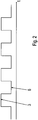
- FIGS. 2 to 4 show the time course of data packets 3, which are transmitted by means of a respective data line (1, 2).
- Each data packet 3 has a predetermined length, which depends on the number of bus subscribers (S1, S2, S3, S4) of the bus system.
- the data transmission is interrupted for a predetermined period of time, so that two temporally successive data packets 3 are temporally spaced apart by means of a transmission pause 6.
- the data packet 4 sent at the time is immediately interrupted and an emergency signal 5 from the respective bus subscriber (S1, S2, S3, S4) or the master module M sent as in FIG. 3 shown.
- This emergency signal 5 causes an immediate shutdown of all bus subscribers (S1, S2, S3, S4).
- the interrupted data packet 4 is terminated immediately and not further processed by the bus users (S1, S2, S3, S4).
- a bus subscriber (S1, S2, S3, S4) or the master module M determines an error during a transmission pause 6, the transmission pause 6 is interrupted and an emergency signal 5 from the respective bus subscriber (S1, S2, S3, S4) or the master module M sent as in FIG. 4 shown.
- This emergency signal 5 causes an immediate shutdown of all bus subscribers (S1, S2, S3, S4).
- the respective emergency signal 5 is sent by the respective bus subscriber (S1, S2, S3, S4) on both data lines (1, 2).
- the distress signal 5 is thus sent from the respective bus subscriber (S1, S2, S3, S4) to the master module M on the second data line and sent by the respective bus subscriber (S1, S2, S3, S4) away from the master module M on the first data line 1.
- the respective emergency signal 5 is immediately processed by the bus users (S1, S2, S3, S4) and forwarded to the downstream bus subscriber (S1, S2, S3, S4) at the same time, so that the bus subscribers (S1, S2, S3, S4) immediately switch off.
- the distress signal 5 is thus not first stored and processed, but immediately forwarded to all bus subscribers (S1, S2, S3, S4) and the master module M.
- the emergency signal 5 preferably has a length that is shorter in time than the data packets (3, 4) and / or the transmission pause 6.
Landscapes
- Engineering & Computer Science (AREA)
- Computer Networks & Wireless Communication (AREA)
- Signal Processing (AREA)
- Small-Scale Networks (AREA)
Applications Claiming Priority (2)
| Application Number | Priority Date | Filing Date | Title |
|---|---|---|---|
| DE102016005312 | 2016-05-02 | ||
| PCT/EP2017/025018 WO2017190843A1 (de) | 2016-05-02 | 2017-02-02 | Verfahren zur initialisierung eines bussystems und bussystem |
Publications (2)
| Publication Number | Publication Date |
|---|---|
| EP3453143A1 EP3453143A1 (de) | 2019-03-13 |
| EP3453143B1 true EP3453143B1 (de) | 2019-08-07 |
Family
ID=57995171
Family Applications (1)
| Application Number | Title | Priority Date | Filing Date |
|---|---|---|---|
| EP17703925.2A Active EP3453143B1 (de) | 2016-05-02 | 2017-02-02 | Verfahren zur initialisierung eines bussystems und bussystem |
Country Status (8)
| Country | Link |
|---|---|
| US (1) | US10541835B2 (da) |
| EP (1) | EP3453143B1 (da) |
| CN (1) | CN109076003B (da) |
| AU (2) | AU2017259931B2 (da) |
| CA (1) | CA3022015C (da) |
| DE (3) | DE102017001733B3 (da) |
| DK (1) | DK3453143T3 (da) |
| WO (1) | WO2017190843A1 (da) |
Families Citing this family (5)
| Publication number | Priority date | Publication date | Assignee | Title |
|---|---|---|---|---|
| EP3453144B1 (de) * | 2016-05-02 | 2019-08-07 | Sew-Eurodrive GmbH & Co. KG | Verfahren zur integration eines weiteren busteilnehmers in ein bussystem und bussystem |
| DE102017208836A1 (de) * | 2017-05-24 | 2018-11-29 | Wago Verwaltungsgesellschaft Mbh | Statussignalausgabe |
| DE102017122437A1 (de) * | 2017-09-27 | 2019-03-28 | Dr. Johannes Heidenhain Gmbh | Bussystem und Slave-Einheit für ein Bussystem |
| DE102020201236A1 (de) * | 2020-01-31 | 2021-08-05 | Geze Gmbh | Wandverschlusssystem |
| DE102020117632B4 (de) * | 2020-07-03 | 2022-03-03 | Krohne Messtechnik Gmbh | Bussystem für eine Prozessanlage |
Family Cites Families (16)
| Publication number | Priority date | Publication date | Assignee | Title |
|---|---|---|---|---|
| US4667323A (en) * | 1985-09-03 | 1987-05-19 | Allen-Bradley Company, Inc. | Industrialized token passing network |
| CH677568A5 (da) * | 1989-03-21 | 1991-05-31 | Datawatt Bv | |
| CH677300A5 (da) * | 1989-03-21 | 1991-04-30 | Asea Brown Boveri | |
| GB2249460B (en) * | 1990-09-19 | 1994-06-29 | Intel Corp | Network providing common access to dissimilar hardware interfaces |
| US6160795A (en) * | 1997-03-21 | 2000-12-12 | Siemens Aktiengesellschaft | Network communication |
| US7251740B2 (en) * | 2004-01-23 | 2007-07-31 | Intel Corporation | Apparatus coupling two circuits having different supply voltage sources |
| DE102005034944B3 (de) | 2005-07-22 | 2006-11-09 | Siemens Ag | Verfahren und Anordnung zur automatischen Konfiguration eines Master-Slave-Feldbussystems |
| WO2009027802A1 (en) * | 2007-08-28 | 2009-03-05 | Nokia Corporation | Method for bus testing and addressing in mass memory components |
| DE102010002758A1 (de) * | 2010-03-11 | 2011-09-15 | Tridonic Gmbh & Co Kg | Bus-Gebäudetechniksystem mit Daisy-Chain Topologie |
| EP2602959B1 (de) * | 2011-12-06 | 2014-06-04 | FESTO AG & Co. KG | Busknoten und Steuerungssystem |
| DE102013201106B4 (de) * | 2013-01-24 | 2014-12-11 | Smiths Heimann Gmbh | Busknoten und Bussystem sowie Verfahren zur Identifikation der Busknoten des Bussystems |
| CN104044968B (zh) * | 2013-03-12 | 2016-01-27 | 上海三菱电梯有限公司 | 电梯层站呼梯装置的设置控制方法 |
| US10089274B2 (en) * | 2013-03-13 | 2018-10-02 | Atieva, Inc. | Dual voltage communication bus |
| US9372818B2 (en) * | 2013-03-15 | 2016-06-21 | Atmel Corporation | Proactive quality of service in multi-matrix system bus |
| DE112014001621T5 (de) | 2013-03-25 | 2015-12-24 | Mitsubishi Electric Corporation | Bus-Master, Bussystem und Bussteuerungsverfahren |
| CN203178732U (zh) * | 2013-04-01 | 2013-09-04 | 暨南大学 | 一种消防信息传输主机板 |
-
2017
- 2017-02-02 CA CA3022015A patent/CA3022015C/en active Active
- 2017-02-02 EP EP17703925.2A patent/EP3453143B1/de active Active
- 2017-02-02 US US16/098,666 patent/US10541835B2/en active Active
- 2017-02-02 AU AU2017259931A patent/AU2017259931B2/en active Active
- 2017-02-02 DK DK17703925.2T patent/DK3453143T3/da active
- 2017-02-02 WO PCT/EP2017/025018 patent/WO2017190843A1/de not_active Ceased
- 2017-02-02 CN CN201780027151.8A patent/CN109076003B/zh active Active
- 2017-02-02 DE DE102017001733.6A patent/DE102017001733B3/de active Active
- 2017-02-02 DE DE102017001734.4A patent/DE102017001734B3/de active Active
- 2017-02-02 DE DE102017000932.5A patent/DE102017000932B3/de active Active
-
2019
- 2019-08-16 AU AU2019216727A patent/AU2019216727B2/en active Active
Non-Patent Citations (1)
| Title |
|---|
| None * |
Also Published As
| Publication number | Publication date |
|---|---|
| BR112018069942A2 (pt) | 2019-02-05 |
| EP3453143A1 (de) | 2019-03-13 |
| DE102017001733B3 (de) | 2017-07-13 |
| DK3453143T3 (da) | 2019-10-07 |
| CN109076003A (zh) | 2018-12-21 |
| DE102017001734B3 (de) | 2017-08-10 |
| DE102017000932B3 (de) | 2017-08-10 |
| AU2017259931B2 (en) | 2019-05-16 |
| CN109076003B (zh) | 2021-01-26 |
| AU2019216727A1 (en) | 2019-09-05 |
| CA3022015A1 (en) | 2017-11-09 |
| US20190149356A1 (en) | 2019-05-16 |
| CA3022015C (en) | 2023-12-05 |
| US10541835B2 (en) | 2020-01-21 |
| WO2017190843A1 (de) | 2017-11-09 |
| AU2019216727B2 (en) | 2021-07-01 |
| AU2017259931A1 (en) | 2018-10-11 |
Similar Documents
| Publication | Publication Date | Title |
|---|---|---|
| EP3453144B1 (de) | Verfahren zur integration eines weiteren busteilnehmers in ein bussystem und bussystem | |
| EP3453143B1 (de) | Verfahren zur initialisierung eines bussystems und bussystem | |
| DE10261174B3 (de) | Automatische Adressierung auf Bussystemen | |
| EP2936747B1 (de) | Datenübertragung unter nutzung eines protokollausnahmezustands | |
| DE102010009775B4 (de) | Schaltschranküberwachungseinrichtung | |
| EP2356528B1 (de) | Verfahren zum übertragen von daten in einem automatisierten steuerungssystem | |
| EP2866387A1 (de) | Bussystem und Verfahren zum Betreiben eines solchen Bussystems | |
| CH661399A5 (de) | Fernwirkanlage. | |
| WO2018215289A1 (de) | Moduleinheit zum verbinden eines datenbusteilnehmers | |
| EP3298730B1 (de) | Bussystem und verfahren zum zuteilen von adressen von busteilnehmern eines bussystems | |
| EP3575899B1 (de) | Automatisierungssystem, betriebsverfahren für automatisierungssystem und computerprogrammprodukt | |
| EP3453145B1 (de) | Verfahren zur notabschaltung eines bussystems und bussystem | |
| EP3618020A1 (de) | Kabeladapter zum sammeln und weiterleiten analoger signale von einer mehrzahl von sensoren in einem kraftfahrzeug, sowie verfahren und verwendung hierzu | |
| EP3453156A1 (de) | Verfahren zur zuordnung von adressen an busteilnehmer eines bussystems und bussystem | |
| DE102011115431B4 (de) | Feldbusnetzwerkadapter und Feldbusnetzwerkteilnehmer mit Feldbusanschlüssen | |
| EP2466805A1 (de) | Verfahren zur Datenübertragung zwischen zwei Teilnehmern, Wandler zum Senden und Empfangen von Daten und Datenübertragungsstrecke | |
| EP4300898A2 (de) | Vakuumgerät | |
| EP2875438B1 (de) | Anmeldeverfahren und buskommunikationseinrichtung | |
| DE20201249U1 (de) | Feldbussystem | |
| DE102014201373A1 (de) | Verfahren zum Betreiben eines redundanten Kommunikationsnetzwerkes | |
| DE102016113324A1 (de) | Ethernet-Netzwerk | |
| DE102009056136A1 (de) | Vorrichtung zum Betrieb eines Bussystems | |
| DE102016103791A1 (de) | Betrieb eines Datennetzwerks | |
| DE102012012035A1 (de) | Netzwerk-Protokollfilter | |
| DE2218007B2 (de) | Schaltungsanordnung zur Übertragung von codierten Signalen |
Legal Events
| Date | Code | Title | Description |
|---|---|---|---|
| STAA | Information on the status of an ep patent application or granted ep patent |
Free format text: STATUS: UNKNOWN |
|
| STAA | Information on the status of an ep patent application or granted ep patent |
Free format text: STATUS: THE INTERNATIONAL PUBLICATION HAS BEEN MADE |
|
| PUAI | Public reference made under article 153(3) epc to a published international application that has entered the european phase |
Free format text: ORIGINAL CODE: 0009012 |
|
| STAA | Information on the status of an ep patent application or granted ep patent |
Free format text: STATUS: REQUEST FOR EXAMINATION WAS MADE |
|
| 17P | Request for examination filed |
Effective date: 20181203 |
|
| AK | Designated contracting states |
Kind code of ref document: A1 Designated state(s): AL AT BE BG CH CY CZ DE DK EE ES FI FR GB GR HR HU IE IS IT LI LT LU LV MC MK MT NL NO PL PT RO RS SE SI SK SM TR |
|
| AX | Request for extension of the european patent |
Extension state: BA ME |
|
| GRAP | Despatch of communication of intention to grant a patent |
Free format text: ORIGINAL CODE: EPIDOSNIGR1 |
|
| STAA | Information on the status of an ep patent application or granted ep patent |
Free format text: STATUS: GRANT OF PATENT IS INTENDED |
|
| INTG | Intention to grant announced |
Effective date: 20190326 |
|
| GRAS | Grant fee paid |
Free format text: ORIGINAL CODE: EPIDOSNIGR3 |
|
| GRAA | (expected) grant |
Free format text: ORIGINAL CODE: 0009210 |
|
| STAA | Information on the status of an ep patent application or granted ep patent |
Free format text: STATUS: THE PATENT HAS BEEN GRANTED |
|
| AK | Designated contracting states |
Kind code of ref document: B1 Designated state(s): AL AT BE BG CH CY CZ DE DK EE ES FI FR GB GR HR HU IE IS IT LI LT LU LV MC MK MT NL NO PL PT RO RS SE SI SK SM TR |
|
| DAV | Request for validation of the european patent (deleted) | ||
| DAX | Request for extension of the european patent (deleted) | ||
| REG | Reference to a national code |
Ref country code: GB Ref legal event code: FG4D Free format text: NOT ENGLISH |
|
| REG | Reference to a national code |
Ref country code: CH Ref legal event code: EP Ref country code: CH Ref legal event code: NV Representative=s name: HEPP WENGER RYFFEL AG, CH Ref country code: AT Ref legal event code: REF Ref document number: 1165538 Country of ref document: AT Kind code of ref document: T Effective date: 20190815 |
|
| REG | Reference to a national code |
Ref country code: DE Ref legal event code: R096 Ref document number: 502017001987 Country of ref document: DE |
|
| REG | Reference to a national code |
Ref country code: IE Ref legal event code: FG4D Free format text: LANGUAGE OF EP DOCUMENT: GERMAN |
|
| REG | Reference to a national code |
Ref country code: DK Ref legal event code: T3 Effective date: 20191003 |
|
| REG | Reference to a national code |
Ref country code: SE Ref legal event code: TRGR |
|
| REG | Reference to a national code |
Ref country code: NL Ref legal event code: FP |
|
| REG | Reference to a national code |
Ref country code: LT Ref legal event code: MG4D |
|
| PG25 | Lapsed in a contracting state [announced via postgrant information from national office to epo] |
Ref country code: HR Free format text: LAPSE BECAUSE OF FAILURE TO SUBMIT A TRANSLATION OF THE DESCRIPTION OR TO PAY THE FEE WITHIN THE PRESCRIBED TIME-LIMIT Effective date: 20190807 Ref country code: BG Free format text: LAPSE BECAUSE OF FAILURE TO SUBMIT A TRANSLATION OF THE DESCRIPTION OR TO PAY THE FEE WITHIN THE PRESCRIBED TIME-LIMIT Effective date: 20191107 Ref country code: NO Free format text: LAPSE BECAUSE OF FAILURE TO SUBMIT A TRANSLATION OF THE DESCRIPTION OR TO PAY THE FEE WITHIN THE PRESCRIBED TIME-LIMIT Effective date: 20191107 Ref country code: PT Free format text: LAPSE BECAUSE OF FAILURE TO SUBMIT A TRANSLATION OF THE DESCRIPTION OR TO PAY THE FEE WITHIN THE PRESCRIBED TIME-LIMIT Effective date: 20191209 Ref country code: LT Free format text: LAPSE BECAUSE OF FAILURE TO SUBMIT A TRANSLATION OF THE DESCRIPTION OR TO PAY THE FEE WITHIN THE PRESCRIBED TIME-LIMIT Effective date: 20190807 |
|
| PG25 | Lapsed in a contracting state [announced via postgrant information from national office to epo] |
Ref country code: RS Free format text: LAPSE BECAUSE OF FAILURE TO SUBMIT A TRANSLATION OF THE DESCRIPTION OR TO PAY THE FEE WITHIN THE PRESCRIBED TIME-LIMIT Effective date: 20190807 Ref country code: GR Free format text: LAPSE BECAUSE OF FAILURE TO SUBMIT A TRANSLATION OF THE DESCRIPTION OR TO PAY THE FEE WITHIN THE PRESCRIBED TIME-LIMIT Effective date: 20191108 Ref country code: IS Free format text: LAPSE BECAUSE OF FAILURE TO SUBMIT A TRANSLATION OF THE DESCRIPTION OR TO PAY THE FEE WITHIN THE PRESCRIBED TIME-LIMIT Effective date: 20191207 Ref country code: LV Free format text: LAPSE BECAUSE OF FAILURE TO SUBMIT A TRANSLATION OF THE DESCRIPTION OR TO PAY THE FEE WITHIN THE PRESCRIBED TIME-LIMIT Effective date: 20190807 Ref country code: AL Free format text: LAPSE BECAUSE OF FAILURE TO SUBMIT A TRANSLATION OF THE DESCRIPTION OR TO PAY THE FEE WITHIN THE PRESCRIBED TIME-LIMIT Effective date: 20190807 Ref country code: ES Free format text: LAPSE BECAUSE OF FAILURE TO SUBMIT A TRANSLATION OF THE DESCRIPTION OR TO PAY THE FEE WITHIN THE PRESCRIBED TIME-LIMIT Effective date: 20190807 |
|
| PG25 | Lapsed in a contracting state [announced via postgrant information from national office to epo] |
Ref country code: TR Free format text: LAPSE BECAUSE OF FAILURE TO SUBMIT A TRANSLATION OF THE DESCRIPTION OR TO PAY THE FEE WITHIN THE PRESCRIBED TIME-LIMIT Effective date: 20190807 |
|
| PG25 | Lapsed in a contracting state [announced via postgrant information from national office to epo] |
Ref country code: PL Free format text: LAPSE BECAUSE OF FAILURE TO SUBMIT A TRANSLATION OF THE DESCRIPTION OR TO PAY THE FEE WITHIN THE PRESCRIBED TIME-LIMIT Effective date: 20190807 Ref country code: RO Free format text: LAPSE BECAUSE OF FAILURE TO SUBMIT A TRANSLATION OF THE DESCRIPTION OR TO PAY THE FEE WITHIN THE PRESCRIBED TIME-LIMIT Effective date: 20190807 Ref country code: EE Free format text: LAPSE BECAUSE OF FAILURE TO SUBMIT A TRANSLATION OF THE DESCRIPTION OR TO PAY THE FEE WITHIN THE PRESCRIBED TIME-LIMIT Effective date: 20190807 |
|
| PG25 | Lapsed in a contracting state [announced via postgrant information from national office to epo] |
Ref country code: SM Free format text: LAPSE BECAUSE OF FAILURE TO SUBMIT A TRANSLATION OF THE DESCRIPTION OR TO PAY THE FEE WITHIN THE PRESCRIBED TIME-LIMIT Effective date: 20190807 Ref country code: IS Free format text: LAPSE BECAUSE OF FAILURE TO SUBMIT A TRANSLATION OF THE DESCRIPTION OR TO PAY THE FEE WITHIN THE PRESCRIBED TIME-LIMIT Effective date: 20200224 Ref country code: CZ Free format text: LAPSE BECAUSE OF FAILURE TO SUBMIT A TRANSLATION OF THE DESCRIPTION OR TO PAY THE FEE WITHIN THE PRESCRIBED TIME-LIMIT Effective date: 20190807 Ref country code: SK Free format text: LAPSE BECAUSE OF FAILURE TO SUBMIT A TRANSLATION OF THE DESCRIPTION OR TO PAY THE FEE WITHIN THE PRESCRIBED TIME-LIMIT Effective date: 20190807 |
|
| REG | Reference to a national code |
Ref country code: DE Ref legal event code: R097 Ref document number: 502017001987 Country of ref document: DE |
|
| PLBE | No opposition filed within time limit |
Free format text: ORIGINAL CODE: 0009261 |
|
| STAA | Information on the status of an ep patent application or granted ep patent |
Free format text: STATUS: NO OPPOSITION FILED WITHIN TIME LIMIT |
|
| PG2D | Information on lapse in contracting state deleted |
Ref country code: IS |
|
| 26N | No opposition filed |
Effective date: 20200603 |
|
| REG | Reference to a national code |
Ref country code: BE Ref legal event code: MM Effective date: 20200229 |
|
| PG25 | Lapsed in a contracting state [announced via postgrant information from national office to epo] |
Ref country code: MC Free format text: LAPSE BECAUSE OF FAILURE TO SUBMIT A TRANSLATION OF THE DESCRIPTION OR TO PAY THE FEE WITHIN THE PRESCRIBED TIME-LIMIT Effective date: 20190807 Ref country code: LU Free format text: LAPSE BECAUSE OF NON-PAYMENT OF DUE FEES Effective date: 20200202 |
|
| PG25 | Lapsed in a contracting state [announced via postgrant information from national office to epo] |
Ref country code: IE Free format text: LAPSE BECAUSE OF NON-PAYMENT OF DUE FEES Effective date: 20200202 |
|
| PG25 | Lapsed in a contracting state [announced via postgrant information from national office to epo] |
Ref country code: BE Free format text: LAPSE BECAUSE OF NON-PAYMENT OF DUE FEES Effective date: 20200229 |
|
| PG25 | Lapsed in a contracting state [announced via postgrant information from national office to epo] |
Ref country code: MT Free format text: LAPSE BECAUSE OF FAILURE TO SUBMIT A TRANSLATION OF THE DESCRIPTION OR TO PAY THE FEE WITHIN THE PRESCRIBED TIME-LIMIT Effective date: 20190807 Ref country code: CY Free format text: LAPSE BECAUSE OF FAILURE TO SUBMIT A TRANSLATION OF THE DESCRIPTION OR TO PAY THE FEE WITHIN THE PRESCRIBED TIME-LIMIT Effective date: 20190807 |
|
| PG25 | Lapsed in a contracting state [announced via postgrant information from national office to epo] |
Ref country code: MK Free format text: LAPSE BECAUSE OF FAILURE TO SUBMIT A TRANSLATION OF THE DESCRIPTION OR TO PAY THE FEE WITHIN THE PRESCRIBED TIME-LIMIT Effective date: 20190807 |
|
| PG25 | Lapsed in a contracting state [announced via postgrant information from national office to epo] |
Ref country code: SI Free format text: LAPSE BECAUSE OF FAILURE TO SUBMIT A TRANSLATION OF THE DESCRIPTION OR TO PAY THE FEE WITHIN THE PRESCRIBED TIME-LIMIT Effective date: 20190807 |
|
| PGFP | Annual fee paid to national office [announced via postgrant information from national office to epo] |
Ref country code: DE Payment date: 20250228 Year of fee payment: 9 |
|
| PGFP | Annual fee paid to national office [announced via postgrant information from national office to epo] |
Ref country code: DK Payment date: 20250214 Year of fee payment: 9 Ref country code: FI Payment date: 20250218 Year of fee payment: 9 |
|
| PGFP | Annual fee paid to national office [announced via postgrant information from national office to epo] |
Ref country code: SE Payment date: 20250103 Year of fee payment: 9 |
|
| PGFP | Annual fee paid to national office [announced via postgrant information from national office to epo] |
Ref country code: AT Payment date: 20250207 Year of fee payment: 9 Ref country code: CH Payment date: 20250301 Year of fee payment: 9 |
|
| PGFP | Annual fee paid to national office [announced via postgrant information from national office to epo] |
Ref country code: IT Payment date: 20250110 Year of fee payment: 9 Ref country code: GB Payment date: 20250102 Year of fee payment: 9 |
|
| PGFP | Annual fee paid to national office [announced via postgrant information from national office to epo] |
Ref country code: FR Payment date: 20251231 Year of fee payment: 10 |
|
| PGFP | Annual fee paid to national office [announced via postgrant information from national office to epo] |
Ref country code: NL Payment date: 20260106 Year of fee payment: 10 |
|
| REG | Reference to a national code |
Ref country code: CH Ref legal event code: U11 Free format text: ST27 STATUS EVENT CODE: U-0-0-U10-U11 (AS PROVIDED BY THE NATIONAL OFFICE) Effective date: 20260301 |