EP3453083B1 - Wärmetauscher mit konischem lichtabstreifer für hochleistungslasersysteme und andere systeme - Google Patents
Wärmetauscher mit konischem lichtabstreifer für hochleistungslasersysteme und andere systeme Download PDFInfo
- Publication number
- EP3453083B1 EP3453083B1 EP17711810.6A EP17711810A EP3453083B1 EP 3453083 B1 EP3453083 B1 EP 3453083B1 EP 17711810 A EP17711810 A EP 17711810A EP 3453083 B1 EP3453083 B1 EP 3453083B1
- Authority
- EP
- European Patent Office
- Prior art keywords
- heat exchanger
- passage
- tapered
- absorptive
- heat
- Prior art date
- Legal status (The legal status is an assumption and is not a legal conclusion. Google has not performed a legal analysis and makes no representation as to the accuracy of the status listed.)
- Active
Links
Images



Classifications
-
- H—ELECTRICITY
- H01—ELECTRIC ELEMENTS
- H01S—DEVICES USING THE PROCESS OF LIGHT AMPLIFICATION BY STIMULATED EMISSION OF RADIATION [LASER] TO AMPLIFY OR GENERATE LIGHT; DEVICES USING STIMULATED EMISSION OF ELECTROMAGNETIC RADIATION IN WAVE RANGES OTHER THAN OPTICAL
- H01S3/00—Lasers, i.e. devices using stimulated emission of electromagnetic radiation in the infrared, visible or ultraviolet wave range
- H01S3/02—Constructional details
- H01S3/04—Arrangements for thermal management
-
- G—PHYSICS
- G02—OPTICS
- G02B—OPTICAL ELEMENTS, SYSTEMS OR APPARATUS
- G02B5/00—Optical elements other than lenses
- G02B5/003—Light absorbing elements
-
- H—ELECTRICITY
- H01—ELECTRIC ELEMENTS
- H01S—DEVICES USING THE PROCESS OF LIGHT AMPLIFICATION BY STIMULATED EMISSION OF RADIATION [LASER] TO AMPLIFY OR GENERATE LIGHT; DEVICES USING STIMULATED EMISSION OF ELECTROMAGNETIC RADIATION IN WAVE RANGES OTHER THAN OPTICAL
- H01S3/00—Lasers, i.e. devices using stimulated emission of electromagnetic radiation in the infrared, visible or ultraviolet wave range
- H01S3/005—Optical devices external to the laser cavity, specially adapted for lasers, e.g. for homogenisation of the beam or for manipulating laser pulses, e.g. pulse shaping
-
- H—ELECTRICITY
- H01—ELECTRIC ELEMENTS
- H01S—DEVICES USING THE PROCESS OF LIGHT AMPLIFICATION BY STIMULATED EMISSION OF RADIATION [LASER] TO AMPLIFY OR GENERATE LIGHT; DEVICES USING STIMULATED EMISSION OF ELECTROMAGNETIC RADIATION IN WAVE RANGES OTHER THAN OPTICAL
- H01S3/00—Lasers, i.e. devices using stimulated emission of electromagnetic radiation in the infrared, visible or ultraviolet wave range
- H01S3/02—Constructional details
- H01S3/04—Arrangements for thermal management
- H01S3/0405—Conductive cooling, e.g. by heat sinks or thermo-electric elements
-
- H—ELECTRICITY
- H01—ELECTRIC ELEMENTS
- H01S—DEVICES USING THE PROCESS OF LIGHT AMPLIFICATION BY STIMULATED EMISSION OF RADIATION [LASER] TO AMPLIFY OR GENERATE LIGHT; DEVICES USING STIMULATED EMISSION OF ELECTROMAGNETIC RADIATION IN WAVE RANGES OTHER THAN OPTICAL
- H01S3/00—Lasers, i.e. devices using stimulated emission of electromagnetic radiation in the infrared, visible or ultraviolet wave range
- H01S3/02—Constructional details
- H01S3/04—Arrangements for thermal management
- H01S3/0401—Arrangements for thermal management of optical elements being part of laser resonator, e.g. windows, mirrors, lenses
-
- H—ELECTRICITY
- H01—ELECTRIC ELEMENTS
- H01S—DEVICES USING THE PROCESS OF LIGHT AMPLIFICATION BY STIMULATED EMISSION OF RADIATION [LASER] TO AMPLIFY OR GENERATE LIGHT; DEVICES USING STIMULATED EMISSION OF ELECTROMAGNETIC RADIATION IN WAVE RANGES OTHER THAN OPTICAL
- H01S3/00—Lasers, i.e. devices using stimulated emission of electromagnetic radiation in the infrared, visible or ultraviolet wave range
- H01S3/02—Constructional details
- H01S3/04—Arrangements for thermal management
- H01S3/0407—Liquid cooling, e.g. by water
-
- H—ELECTRICITY
- H01—ELECTRIC ELEMENTS
- H01S—DEVICES USING THE PROCESS OF LIGHT AMPLIFICATION BY STIMULATED EMISSION OF RADIATION [LASER] TO AMPLIFY OR GENERATE LIGHT; DEVICES USING STIMULATED EMISSION OF ELECTROMAGNETIC RADIATION IN WAVE RANGES OTHER THAN OPTICAL
- H01S3/00—Lasers, i.e. devices using stimulated emission of electromagnetic radiation in the infrared, visible or ultraviolet wave range
- H01S3/05—Construction or shape of optical resonators; Accommodation of active medium therein; Shape of active medium
- H01S3/08—Construction or shape of optical resonators or components thereof
- H01S3/08018—Mode suppression
- H01S3/0804—Transverse or lateral modes
- H01S3/0805—Transverse or lateral modes by apertures, e.g. pin-holes or knife-edges
Definitions
- This disclosure is generally directed to laser systems. More specifically, this disclosure is directed to heat exchangers with tapered light scrapers for high-power laser systems and other systems.
- High-power laser systems are being developed for a number of military and commercial applications.
- a master oscillator/power amplifier (MOPA) configuration is used.
- the master oscillator generates a low-power optical signal that is then amplified by a power amplifier to generate a high-power output beam.
- MOPA master oscillator/power amplifier
- stray electro-optical radiation is typically present to some extent in laser systems, such as due to fluorescence or amplified spontaneous emissions (ASE).
- the stray radiation denotes optical energy that does not follow a desired path in the laser systems.
- This stray radiation can strike other components in the laser systems and can be absorbed by those components.
- the heating of optical device mounts can cause the mounts to bend or warp, creating pointing errors.
- the heating of housings, mounts, fasteners, and adhesives can also lead to material failures in those components.
- the heating of various component surfaces can further lead to off-gassing or out-gassing from the surfaces of components.
- EP 1 492 207 A2 discloses a laser gain device holding a laser slab which is pumped by pump energy from at least one diode array assembly.
- An angle at which pump energy from the diode array assembly impinges the laser slab is adjustable via angle adjustment means.
- the laser slab is mounted between edge bars which have laser slab spacers extending therethrough, allowing laser slabs of different widths to be mounted within the laser gain device.
- One or more pump energy shields are used to control the amount of pump energy entering the laser slab, and cooling liquid conduits are provided throughout components of the laser gain device, serving to conductively cool a heat shield.
- a diode array mount which supports the diode array assembly includes two lever portions pivoting around a fulcrum with respect to a slab housing. An adjustment screw connected to one of the two lever portions adjusts a pump energy angle at which pump energy from an energy emission region impinges on the solid state laser slab.
- EP 1 480 299 A1 discloses methods, systems and apparatus for amplifying a source light in a solid state laser.
- An amplifier module for the solid state laser suitably includes a disk having two substantially parallel surfaces and an optical gain material.
- Diode bars are arranged about the perimeter of the disk and configured to provide optical pump radiation to the optical gain material in the disk.
- Each of the plurality of diode bars is spatially aligned with the disk in such a manner as to produce substantially uniform gain across the optical gain material.
- the fast axes of the diode bars may be aligned to be parallel or orthogonal to the parallel surfaces of the disk
- EP 1 003 252 A2 discloses a gain module for a master oscillator pumped amplifier system of a solid state laser including a ceramic housing supporting a Nd:YAG lasing slab therein.
- the slab is fixed relative to the housing by a pair of oppositely disposed compliant and optically transmissive securing members frictionally wedged between the housing and the lasing slab.
- Fluid passages are formed in the housing so as to communicate with the lasing slab.
- the compliant securing members prevent the slab from vibrating.
- the securing members are formed as U-shaped polycarbonate bars frictionally engaging the slab on a first surface and positionally adjustable driver bars coupled to the housing via a set screw block on a second surface.
- This disclosure provides heat exchangers with tapered light scrapers for high-power laser systems and other systems.
- the present disclosure provides an apparatus comprising: a heat exchanger comprising: a body having a passage through the body, the passage defining apertures on multiple sides of the body, the passage configured to allow optical signals to pass through the body; one or more tapered edges at least partially around one or more of the apertures, each tapered edge comprising a reflective surface configured to reflect optical radiation occurring upon incidence of the optical signals inward into the passage; and one or more absorptive surfaces within the passage, the one or more absorptive surfaces configured to absorb the reflected optical radiation; the heat exchanger configured to convert the absorbed optical radiation into heat; the body further comprising one or more cooling channels configured to receive coolant that absorbs the heat.
- the present disclosure provides a system comprising: a laser gain medium configured to amplify optical signals; and the apparatus of the first aspect.
- the present disclosure provides a method comprising: passing optical signals into a passage through a body of a heat exchanger, the passage defining apertures on multiple sides of the body; reflecting optical radiation occurring upon incidence of the optical signals inward into the passage using one or more tapered edges at least partially around one or more of the apertures, each tapered edge comprising a reflective surface; absorbing the reflected optical radiation using one or more absorptive surfaces within the passage; converting the absorbed optical radiation into heat; and transferring the heat to coolant within one or more cooling channels of the heat exchanger.
- the present disclosure provides a method comprising: obtaining a laser gain medium configured to output optical signals; and inserting the apparatus of the first aspect into an optical path of the optical signals.
- FIGURES 1 through 7B described below, and the various embodiments used to describe the principles of the present invention in this patent document are by way of illustration only and should not be construed in any way to limit the scope of the invention. Those skilled in the art will understand that the principles of the present invention may be implemented in any type of suitably arranged device or system.
- FIGURE 1 illustrates an example laser system 100 with a heat exchanger having a tapered light scraper according to this disclosure.
- the laser system 100 includes a master oscillator 102 and a power amplifier 104.
- the laser system 100 therefore has a master oscillator/power amplifier (MOPA) configuration.
- MOPA master oscillator/power amplifier
- the master oscillator 102 generally operates to generate low-power optical signals 106.
- the low-power optical signals 106 could denote any suitable optical signals having relatively low power.
- the low-power optical signals 106 could include optical signals having a continuous wave (CW) output, a continuous pulse train (CPT), a pulse burst, or any of various other waveforms.
- the master oscillator 102 includes any suitable structure(s) for generating one or more low-power optical signals.
- the master oscillator 102 includes a fiber laser.
- the power amplifier 104 receives the low-power optical signals 106 from the master oscillator 102 and pump power 108 from one or more pump sources 110.
- the power amplifier 104 generally operates to amplify the low-power optical signals 106 and generate high-power optical signals 112.
- the power amplifier 104 could amplify a low-power CW or other optical signal into a high-power CW or other optical signal having ten kilowatts of power or more.
- the received pump power 108 provides the necessary population inversion in the power amplifier's gain medium for this amplification.
- the power amplifier 104 includes any suitable structure for amplifying optical signals. In some embodiments, the power amplifier 104 includes at least one planar waveguide as its gain medium. Each pump source 110 includes any suitable structure for generating optical power used by a power amplifier for amplification. In some embodiments, each pump source 110 includes one or more laser diodes, such as one or more laser diode arrays, or other light sources.
- the high-power optical signals 112 are provided to an output expander and collimator 114, which produces a high-power output beam 116.
- the output expander and collimator 114 includes any suitable structure(s) for expanding and collimating optical signals, such as one or more optical devices like mirrors and lenses. However, any other or additional modifications could be made to the high-power optical signals 112 to generate the high-power output beam 116.
- first stray radiation 118 in FIGURE 1 could be caused by fluorescence or amplified spontaneous emissions (ASE) within the power amplifier 104.
- the high-power optical signals 112 may be emitted from the power amplifier 104 with a half-angle of 3°, whereas fluorescence may be emitted from the power amplifier 104 with a half-angle of 35°.
- back-reflections or scatter 120 could occur upon entry of the optical signals 112 into the output expander and collimator 114 or be created within the output expander and collimator 114 itself (such as from mirror or lens surfaces). Left unchecked, this stray radiation can strike other components in the laser system 100, heating those components and causing various problems (including those discussed above).
- reflective devices can be used to reflect stray radiation from certain components of a laser system. While this protects those components, the stray radiation is still reflected onto other components. As the power of laser systems increases, this becomes unacceptable since the power of the stray radiation similarly increases.
- Other conventional approaches pass an optical beam into a thru-hole of a structure, where the structure allows the bulk of the optical beam to pass and absorbs the stray radiation. However, the structure typically develops hot spots due to the stray radiation, particularly in corners of the structure, and those hot spots can be difficult to cool. Still other conventional techniques utilize absorbing aperture plates and light diffractors. Unfortunately, these techniques tend to break down or are unsuitable for use at high laser powers.
- At least one light-scraping heat exchanger 122 is provided in the laser system 100.
- the heat exchanger 122 includes a passage 123 through which an optical beam (such as the high-power optical signals 112) can pass.
- the heat exchanger 122 also absorbs stray radiation (such as the stray radiation 118 and the stray radiation 120) so that the stray radiation cannot damage other components of the laser system 100 or otherwise interfere with operation of the laser system 100.
- the heat exchanger 122 includes one or more cooling channels 124 through which a coolant (such as a fluid like gas or liquid) can flow through the heat exchanger 122.
- the coolant absorbs heat from the heat exchanger 122 and transports the heat out of the laser system 100.
- Each cooling channel 124 could have any suitable size, shape, and dimensions, and any number of cooling channels 124 could be used with the heat exchanger 122. Also, any suitable coolant could be used to transport heat away from the heat exchanger 122.
- the heat exchanger 122 also includes one or more tapered edges 126, which denote one or more edges where one or more interior surfaces of the heat exchanger 122 (such as one or more surfaces within the passage 123) meet with one or more outer surfaces of the heat exchanger 122.
- the tapered edges 126 include reflective surfaces and in this example are located around input and output apertures formed by the passage 123 through the heat exchanger 122.
- the tapered edges 126 reflect stray radiation into the passage 123, where the stray radiation is substantially absorbed by one or more absorptive surfaces within the passage 123.
- the absorbed stray radiation is converted into thermal energy, most or all of which is absorbed by the coolant flowing through the cooling channels 124.
- the stray radiation is reflected by the tapered edges 126 so that the stray radiation is absorbed by the heat exchanger 122 near the locations of the cooling channels 124 in order to facilitate easier rejection of the thermal energy from the laser system 100.
- the amount of stray radiation is substantially reduced in the laser system 100, which helps to protect other components of the laser system 100 and ensure proper operation of the laser system 100.
- the tapered edges 126 of the heat exchanger 122 help to diffuse the stray radiation so that the heat exchanger 122 is far less likely to develop hot spots that cannot be effectively cooled.
- the heat exchanger 122 here represents a single component that can scrape, diffuse, absorb, and reject stray energy in the laser system 100. Performing all of these functions using a single component can help to reduce the size, weight, cost, and complexity of the laser system 100.
- the design of the heat exchanger 122 can help to reduce or minimize the number of "bounces" that stray radiation experiences within the laser system 100.
- the heat exchanger 122 could be formed from any suitable material(s), such as when the body of the heat exchanger 122 is formed from one or more metals like an aluminum alloy or a copper alloy.
- the heat exchanger 122 could also be formed in any suitable manner, such as by using one or any combination of casting, machining, etching, brazing, friction welding, and diffusion bonding.
- the tapered edges 126 of the heat exchanger 122 could denote reflective surfaces, layers, or coatings, such as gold.
- the tapered edges 126 could also be formed in any suitable manner, such as by machining the body of the heat exchanger 122 and depositing reflective material onto the body.
- FIGURE 1 illustrates one example of a laser system 100 with a heat exchanger having a tapered light scraper
- various changes may be made to FIGURE 1 .
- the sizes, shapes, and relative dimensions of the various components in FIGURE 1 are for illustration only.
- the specific arrangement of components in FIGURE 1 could vary as needed or desired.
- FIGURE 1 illustrates one example environment in which a light-scraping heat exchanger could be used.
- the light-scraping heat exchangers described in this patent document could find use in any other suitable system.
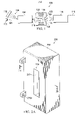
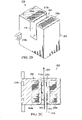
- FIGURES 2A through 2D illustrate a first example heat exchanger 200 with a tapered light scraper according to this disclosure.
- FIGURE 2A illustrates the heat exchanger 200
- FIGURE 2B illustrates a cross-section of the heat exchanger 200 along dashed line 2B in FIGURE 2A
- FIGURE 2C illustrates a top view of the cross-section from FIGURE 2B
- FIGURE 2D illustrates an example use of the heat exchanger 200.
- the heat exchanger 200 shown in FIGURES 2A through 2D could, for example, denote the heat exchanger 122 in FIGURE 1 .
- the heat exchanger 200 includes a main body 202, which forms the bulk of the heat exchanger 200.
- the body 202 could be formed from one or more metals like an aluminum alloy or a copper alloy.
- the body 202 may be formed of any material that provides suitable heat flux reduction.
- a passage 204 extends through the body 202, which allows optical signals 206 to pass through the body 202.
- the passage 204 denotes any suitable path for optical signals through the body 202.
- the passage 204 has substantially flat interior surfaces that are substantially parallel to each other, and the passage 204 opens to two different sides of the body 202.
- This example passage 204 is for illustration only.
- the passage 204 could have any other suitable size, shape, and dimensions.
- the passage 204 could also open to two or more sides of the body 202.
- One or more cooling channels 208a-208b are formed in the body 202.
- the cooling channels 208a-208b allow coolant to flow through the body 202 in order to remove thermal energy from the heat exchanger 200.
- the cooling channels 208a-208b have a generally rectangular cross-section, although each cooling channel 208a-208b could have any suitable size, shape, and dimensions.
- the cooling channels 208a-208b here are arranged to be close to the passage 204, allowing coolant in the cooling channels 208a-208b to quickly absorb thermal energy that is being absorbed by the body 202.
- the rectangular cross-section of the cooling channels 208a-208b extends in a direction substantially parallel to the passage 204, which allows the cooling channels 208a-208b to extract heat along a substantial portion of the passage 204.
- the cooling channels 208a-208b are shown as being patterned in some way. This indicates that the cooling channels 208a-208b could include fins, pins, or other structures that extend into the cooling channels 208a-208b in order to increase the surface area that is contacted by the coolant. Any suitable structures or patterning could be used in the cooling channels 208a-208b, and the structures or patterning could be formed in any suitable manner.
- the passage 204 in the heat exchanger 200 includes one or more absorptive surfaces 210a-210b.
- the absorptive surfaces 210a-210b denote portions of the heat exchanger 200 that are designed to absorb stray radiation.
- the absorptive surfaces 210a-210b could be formed in various ways. For instance, the absorptive surfaces 210a-210b could denote oxidized or black anodized portions of the body 202 or other oxidized or black anodized material(s).
- the absorptive surfaces 210a-210b could also denote one or more absorptive materials deposited onto the surfaces of the body 202 that form the passage 204, such as black chrome.
- the absorptive surfaces 210a-210b could further denote surface features that are etched into or otherwise formed in or on the body 202 to help absorb radiation.
- tapered edges 212 are formed in the body 202.
- the tapered edges 212 denote edges where interior surfaces of the heat exchanger 200 meet with outer surfaces of the heat exchanger 200.
- the tapered edges 212 are located around the apertures formed by the passage 204 and denote reflective surfaces of the body 202, such as those formed by depositing one or more metals like gold or other reflective material(s) onto the body 202.
- the tapered edges 212 could denote straight, curved, conic section, or other surfaces that help to reflect stray radiation inward into the passage 204.
- the exact geometry or geometries of the tapered edges 212 could vary as needed or desired.
- the general purpose of the tapered edges 212 is to reflect stray radiation inward into the passage 204, ideally in a manner that diffuses the stray radiation to thereby expand the surface area of the body 202 being struck by the stray radiation. This helps to reduce the heat flux of the stray radiation on the body 202 to the point where the heat flux can be effectively converted into heat and removed from the body 202.
- FIGURE 2C An example operation of the tapered edges 212 is illustrated in FIGURE 2C , where incoming stray radiation 214 is reflected off one of the tapered edges 212.
- the bottom right tapered edge 212 reflects the incoming stray radiation 214 into the passage 204 and towards the absorptive surface 210a.
- the bottom left tapered edge 212 could similarly reflect incoming stray radiation into the passage 204 and towards the absorptive surface 210b.
- the top tapered edges 212 could similarly reflect incoming stray radiation into the passage 204 and towards the absorptive surfaces 210a-210b.
- the body 202 could include one or more tapered edges on only one side of the body 202. This may be useful, for example, when stray radiation would typically reach one side of the heat exchanger 200 but not the other.
- the heat exchanger 200 may optionally include one or more connection points 216a-216b, which can be used to couple or secure the heat exchanger 200 to a package or platform. Any suitable connection mechanism or mechanisms could be used with the heat exchanger 200, such as bolts, screws, or pins.
- the type(s) and arrangement(s) of the connection points 216a-216b can vary in a number of ways based on how the heat exchanger 200 is to be installed. In this particular example, the connection points 216a can receive bolts or screws, while the connection points 216b can receive alignment pins.
- FIGURE 2D An example of the diffusion of stray radiation 214 by the heat exchanger 200 is shown in FIGURE 2D .
- the stray radiation 214 has a smaller width 250 prior to striking and reflecting off the tapered edge 212. Without the tapering of the edge, substantially all of the stray radiation 214 could be absorbed within a much smaller area of the heat exchanger 200. This could rapidly increase the temperature of that portion of the heat exchanger 200 and actually damage the heat exchanger 200.
- the stray radiation 214 is reflected and diffused so that a width 252 of the stray radiation 214 striking the heat exchanger 200 is much larger than the width 250.
- the width 252 could be ten to twenty times larger than the width 250, although other ratios could also be used.
- the diffusion of the stray radiation 214 helps to reduce the heat flux striking any specific portion of the heat exchanger 200. This results in lower temperatures in the heat exchanger 200, which mitigates thermal blooming in the laser path and reduces or eliminates boiling of the coolant.
- the ratio for the diffused radiation can be dependent on various factors (such as the design of the tapering) to maintain acceptable heat exchanger and coolant temperatures.
- FIGURES 2A through 2D illustrate a first example passage 204 through a heat exchanger 200
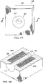
- FIGURES 3A and 3B illustrate a second example heat exchanger 300 with a tapered light scraper according to this disclosure.
- FIGURE 3A illustrates the heat exchanger 300
- FIGURE 3B illustrates a cross-section of the heat exchanger 300 along line 3B of FIGURE 3A .
- the heat exchanger 300 shown in FIGURES 3A and 3B could, for example, denote the heat exchanger 122 in FIGURE 1 .
- the heat exchanger 300 includes a body 302 having a passage 304 extending through the body 302.
- the passage 304 allows optical signals to pass through the body 302.
- the passage 304 is generally cylindrical, has a single curved interior surface, and defines substantially circular apertures on opposite sides of the body 302.
- the body 302 also includes one or more cooling channels 308a-308b, which could denote different cooling channels or a single arced or annular cooling channel.
- the one or more cooling channels 308a-308b allow coolant to flow through the body 302 and remove heat from the heat exchanger 300.
- the passage 304 in the heat exchanger 300 includes at least one absorptive surface 310.
- the absorptive surface 310 is designed to absorb stray radiation and can be formed around most or all of the interior surface of the passage 304.
- the absorptive surface 310 could denote oxidized or black anodized portions of the body 302 or other oxidized or black anodized material(s), one or more absorptive materials deposited onto the surfaces of the body 302 like black chrome, or surface features that are etched into or otherwise formed in or on the body 302 to help absorb radiation.
- At least one tapered edge 312 is formed in the body 302.
- the tapered edges 312 denote edges where one or more interior surfaces of the heat exchanger 300 meet with one or more outer surfaces of the heat exchanger 300.
- the tapered edges 312 are located around the apertures formed by the passage 304 and denote reflective surfaces of the body 302, such as those formed by depositing one or more metals like gold or other reflective material(s) onto the body 302.
- the tapered edges 312 could denote straight, curved, conic section, or other surfaces that help to reflect stray radiation inward into the passage 304.
- the exact geometry or geometries of the tapered edges 312 could vary as needed or desired.
- each tapered edge 312 could surround most or all of an aperture formed by the passage 304, and one or multiple tapered edges 312 could be used on one or multiple sides of the body 302.
- the tapered edge(s) 312 of the heat exchanger 300 can help to scrape and diffuse stray radiation, such as stray radiation in the laser system 100.
- the absorptive surface(s) 310 of the heat exchanger 300 can then absorb the diffused stray radiation, converting the stray radiation into heat that is removed via the cooling channel(s) 308a-308b.
- FIGURES 2A through 3B illustrate examples of heat exchangers 200, 300 with tapered light scrapers
- various changes may be made to FIGURES 2A through 3B .
- the sizes, shapes, and relative dimensions of the various components in each figure are for illustration only.
- heat exchangers having different body, passage, and cooling channel designs could be used, and the apertures defined by the passages through the heat exchangers could have any suitable design.
- FIGURES 4A and 4B illustrate an example distribution of coolant in a heat exchanger 400 with a tapered light scraper according to this disclosure.
- the heat exchanger 400 includes a rectangular passage 404 similar to the heat exchanger 200, although the passage 404 could have any other suitable size, shape, and dimensions.
- the heat exchanger 400 includes at least one input port 406 and at least one output port 408.
- the input port 406 receives incoming coolant prior to the coolant absorbing heat from the heat exchanger 400, and the output port 408 provides outgoing coolant after the coolant absorbs heat from the heat exchanger 400.
- Each input or output port 406-408 includes any suitable pathway for receiving coolant.
- channels 410 and 412 connect the cooling channels on opposite sides of the passage 404. Coolant received through the input port 406 can be provided to the cooling channels on opposite sides of the passage 404, and coolant is provided from the cooling channels on opposite sides of the passage 404 to the output port 408.
- the channels 410 and 412 support this coolant flow through the multiple cooling channels.
- Each channel 410 and 412 can have any suitable size, shape, and dimensions and support any suitable coolant flow.
- FIGURES 4A and 4B illustrate one example of the distribution of coolant in a heat exchanger 400 with a tapered light scraper
- various changes may be made to FIGURES 4A and 4B .
- the sizes, shapes, and relative dimensions of the various components in FIGURES 4A and 4B are for illustration only.
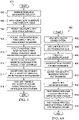
- FIGURE 5 illustrates an example method 500 for using a heat exchanger with a tapered light scraper in a laser system according to this disclosure.
- the method 500 is described with respect to the heat exchangers 122, 200, 300, 400 operating in the system 100 of FIGURE 1 .
- the method 500 could be used by any suitable heat exchanger and in any suitable system.
- a signal beam is generated using a master oscillator at step 502, and the signal beam is amplified using a power amplifier to create a high-power output beam at step 504.
- This could also include the power amplifier 104 amplifying the lower-power signal beam using pump power (such as from one or more pump sources 110) to generate the high-power output beam. Note, however, that any other suitable technique could be used to generate any other suitable laser output.
- the high-power output beam is received at a heat exchanger at step 506 and passes substantially through a passage of the heat exchanger at step 508.
- This could also include allowing most or all of the high-power output beam to pass through the passage 123, 204, 304, 404 of the heat exchanger 122, 200, 300, 400.
- Stray radiation is reflected from one or more tapered edges of the heat exchanger and diffused at step 510.
- This could include, for example, reflecting fluorescence, ASE, or other stray radiation from the tapered edge(s) 126, 212, 312 of the heat exchanger 122, 200, 300, 400.
- This could also include the tapered edge(s) 126, 212, 312 reflecting the stray radiation inward into the passage 123, 204, 304 of the heat exchanger 122, 200, 300, 400. Due to the tapering of the tapered edge(s) 126, 212, 312, the reflected radiation expands or diffuses.
- the stray radiation is absorbed by one or more absorptive surfaces within the passage of the heat exchanger at step 512. This could include, for example, the fluorescence, ASE, or other stray radiation striking the absorptive surfaces 210a-210b, 310 within the passage 123, 204, 304 of the heat exchanger 122, 200, 300, 400.
- the stray radiation is converted into heat at the one or more absorptive surfaces of the heat exchanger at step 514. However, because the radiation has been diffused, the stray radiation results in lower temperatures in the heat exchanger 122, 200, 300, 400.
- At least some of the generated heat is transferred from the heat exchanger into coolant flowing through one or more cooling channels of the heat exchanger at step 516.
- the heat exchanger 122, 200, 300, 400 is able to scrape, diffuse, absorb, and reject stray energy within a laser system.
- the heat exchanger 122, 200, 300, 400 can accomplish this more efficiently and at lower temperatures, which helps to reduce or minimize the risk of damage to the laser system by the stray radiation.
- FIGURE 5 illustrates one example of a method 500 for using a heat exchanger with a tapered light scraper in a laser system
- various changes may be made to FIGURE 5 .
- steps in FIGURE 5 could overlap, occur in parallel, occur in a different order, or occur any number of times.
- FIGURES 6A and 6B illustrate a first example method 600 for forming a heat exchanger with a tapered light scraper according to this disclosure.
- the method 600 is described with respect to the heat exchangers 122, 200, 300, 400.
- the method 600 could be used to form any other suitable heat exchanger.
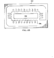
- FIGURE 6A shows one example of a metal foil etch pattern 652 in which one portion 654 defines a passage for optical signals through a heat exchanger and another portion 656 defines cooling channels within the heat exchanger.
- the metal foils could be formed from any suitable materials, such as an aluminum alloy or a copper alloy, and in any suitable manner.
- the metal foils are diffusion bonded or otherwise bonded to form a monolithic slab at step 604, and multiple heat exchangers are formed from the slab at step 606. This could include, for example, using wire electrical discharge machining (EDM) to separate individual instances of the heat exchangers within the slab after the diffusion bonding process.
- EDM wire electrical discharge machining
- External features are machined into each heat exchanger at step 608, and coolant supply and return ports are machined into each heat exchanger at step 610.
- the external features could include features such as the tapered edges 126, 212, 312 and the connection points 216a-216b of the heat exchangers. Any suitable machining technique could be used here, and any other or additional external features could be formed.
- the heat exchanger surfaces are smoothed at step 612, such as via polishing.
- the passages of the heat exchangers are treated to form one or more absorptive surfaces in the passages at step 614. This could include, for example, placing at least one absorptive coating within each passage, oxidizing or anodizing at least one portion within each passage, or depositing oxidized, anodized, black chrome, or other material(s) within each passage.
- At least the passage surfaces are masked and a reflective coating is applied to each heat exchanger at step 616. This could include, for example, depositing a gold coating or other reflective material(s) onto at least the tapered edge(s) 126, 212, 312 of each heat exchanger. At this point, any mask can be removed, and the heat exchangers can be further processed or used.
- FIGURES 7A and 7B illustrate a second example method 700 for forming a heat exchanger with a tapered light scraper according to this disclosure.
- the method 700 is described with respect to the heat exchangers 122, 200, 300, 400.
- the method 700 could be used to form any other suitable heat exchanger.
- FIGURE 7A desired features are machined into a block of metal at step 702, and one or more covers are brazed onto the block at step 704.
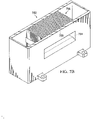
- FIGURE 7B shows one example of a metal block 752 having a passage 754, cooling channels 756, and cooling channels 758 formed in the block 752.
- the block could be formed from any suitable materials, such as an aluminum alloy or a copper alloy, and machined in any suitable manner. Brazing one or more covers onto the block 752 can seal the cooling channels within the resulting structure.
- External features are machined into the heat exchanger at step 706, and coolant supply and return ports are machined into the heat exchanger at step 708.
- the external features could include features such as the tapered edges 126, 212, 312 and the connection points 216a-216b of the heat exchanger. Any suitable machining technique could be used here, and any other or additional external features could be formed.
- the heat exchanger surfaces are smoothed at step 710, such as via polishing.
- the passage of the heat exchanger is treated to form one or more absorptive surfaces in the passage at step 712. This could include, for example, placing at least one absorptive coating within the passage, oxidizing or anodizing at least one portion within the passage, or depositing oxidized, anodized, black chrome, or other material(s) within each passage.
- At least the passage surfaces are masked and a reflective coating is applied to the heat exchanger at step 714. This could include, for example, depositing a gold coating or other reflective material(s) onto at least the tapered edge(s) 126, 212, 312 of the heat exchanger. At this point, any mask can be removed, and the heat exchanger can be further processed or used.
- FIGURES 6A through 7B illustrate examples of method for forming a heat exchanger with a tapered light scraper
- various changes may be made to FIGURES 6A through 7B .
- steps in FIGURES 6A and 7A could overlap, occur in parallel, occur in a different order, or occur any number of times.
- the structures of the metal foil etch pattern 652 and the metal block 752 in FIGURES 6B and 7B are examples only.
- High-power laser systems such as the ones described above, could be used in a large number of military and commercial applications.
- the following discussion provides a description of various example commercial applications. However, the following discussion does not limit this disclosure to any particular applications.
- High-power laser systems could find use in commercial mining applications, such as in drilling, mining, or coring operations.
- high-power laser systems could be used to soften or weaken an earth bed prior to drilling through the earth bed using drill bits. This could allow for fewer drill bit changes and extended lifetimes and reliabilities of the drill bits.
- free-space propagation of a high-power laser beam from an output window of a laser system could be used, allowing deeper penetration at further distances compared to conventional fiber lasers.
- High-power and high-beam quality laser systems could also find use in remote laser welding, cutting, drilling, or heat treating operations, such as in industrial or other automation settings.
- the use of a high-power and high-beam quality laser system allows the processing of thicker materials to occur at larger working distances from the laser system while minimizing the heat-affected zone and maintaining vertical or other cut lines. Among other things, this helps to support welding or cutting operations where proximity to the weld or cut site is difficult or hazardous. It also helps to protect the laser system and possibly any human operators from smoke, debris, or other harmful materials.
- High-power laser systems could further find use in construction and demolition operations.
- Example operations could include metal resurfacing or deslagging, paint removal, and industrial demolition operations.
- High-power laser systems can be used to ablate material much faster and safer compared to conventional operations.
- high-power laser systems could be used to support demolition of nuclear reactors or other hazardous structures.
- the high-power laser systems could be used to cut through contaminated structures like contaminated concrete or nuclear containment vessels or reactors from long distances. This helps to avoid the use of water jet cutting or other techniques that create hazardous waste, such as contaminated water. It also provides improved safety since human operators can remain farther away from contaminated structures being demolished.
- high-power laser systems could find use in power beaming applications, where high-power laser beams are targeted to photovoltaic (solar) cells of remote devices to be recharged.
- High-power laser systems could find use in hazardous material (HAZMAT) applications, where the laser systems are used to heat and decompose hazardous materials into less harmful or non-harmful materials:
Landscapes
- Physics & Mathematics (AREA)
- Electromagnetism (AREA)
- Optics & Photonics (AREA)
- Engineering & Computer Science (AREA)
- Plasma & Fusion (AREA)
- General Physics & Mathematics (AREA)
- Lasers (AREA)
Claims (15)
- Einrichtung, die Folgendes umfasst:einen Wärmetauscher (122; 200; 300; 400), der Folgendes umfasst:einen Körper (202; 302), der einen Durchgang (123; 204; 304; 404) durch den Körper aufweist, wobei der Durchgang Öffnungen an mehreren Seiten des Körpers definiert, wobei der Durchgang konfiguriert ist, um es optischen Signalen (112) zu ermöglichen, den Körper zu durchqueren;eine oder mehrere konische Kanten (126; 212; 312) wenigstens teilweise um eine oder mehrere der Öffnungen herum, wobei jede konische Kante eine reflektierende Oberfläche umfasst, die konfiguriert ist, optische Strahlung (118; 120; 214) zu reflektieren, die beim Einfall der optischen Signale nach innen in den Durchgang auftritt; undeine oder mehrere absorbierende Oberflächen (210a, 210b; 310) innerhalb des Durchgangs, wobei die eine oder die mehreren absorbierenden Oberflächen konfiguriert sind, die reflektierte optische Strahlung zu absorbieren;wobei der Wärmetauscher konfiguriert ist, die absorbierte optische Strahlung in Wärme umzusetzen;der Körper ferner einen oder mehrere Kühlkanäle (124; 208a, 208b; 308a, 308b) umfasst, die konfiguriert sind, Kühlmittel aufzunehmen, das die Wärme absorbiert.
- Einrichtung nach Anspruch 1, wobei:der Körper mehrere im Wesentlichen flache innere Oberflächen, die den Durchgang definieren, und mehrere absorbierende Oberflächen umfasst;die inneren Oberflächen im Wesentlichen parallel zueinander sind; undjede innere Oberfläche eine der absorbierenden Oberflächen aufweist.
- Einrichtung nach Anspruch 1, wobei:der Körper einen im Wesentlichen zylindrischen Durchgang mit einer gekrümmten inneren Oberfläche umfasst; unddie innere Oberfläche die eine oder die mehreren absorbierenden Oberflächen aufweist.
- Einrichtung nach Anspruch 1, wobei:der Durchgang eine oder mehrere innere Oberflächen beinhaltet; undjede konische Kante wenigstens eine der einen oder der mehreren inneren Oberflächen mit wenigstens einer äußeren Oberfläche des Körpers verbindet.
- Einrichtung nach Anspruch 1, wobei jede von mehreren absorbierenden Oberflächen an einen von mehreren Kühlkanälen angrenzt.
- Einrichtung nach Anspruch 1, wobei:der Körper ein oder mehrere Metalle umfasst; undjede konische Kante ein oder mehrere reflektierende Materialien auf dem Körper umfasst; undvorzugsweise wobei:der Körper eine Aluminiumlegierung oder eine Kupferlegierung umfasst; undjede konische Kante eine goldbeschichtete Oberfläche umfasst.
- Einrichtung nach Anspruch 1, wobei jede konische Kante ferner konfiguriert ist, die reflektierte optische Strahlung zu diffundieren, sodass eine Breite der optischen Strahlung, die an der konischen Kante aufgenommen wird, kleiner als eine Breite der reflektierten optischen Strahlung ist, die an einem der einen oder der mehreren absorbierenden Oberflächen aufgenommen wird; oder
wobei jede konische Kante eine gerade Oberfläche, eine gekrümmte Oberfläche oder einen kegeligen Abschnitt umfasst. - System (100), das Folgendes umfasst:ein Laserverstärkungsmedium (104), das konfiguriert ist, optische Signale (106) zu amplifizieren; unddie Einrichtung nach einem der Ansprüche 1 bis 7.
- System nach Anspruch 8, wobei das Laserverstärkungsmedium einen planaren Wellenleiter umfasst.
- Verfahren, das Folgendes umfasst:Durchleiten (508) optischer Signale in einen Durchgang (123; 204; 304; 404) durch einen Körper (202; 302) eines Wärmetauschers, wobei der Durchgang Öffnungen an mehreren Seiten des Körpers definiert;Reflektieren (510) optischer Strahlung (118; 214), die beim Einfall der optischen Signale nach innen in den Durchgang auftritt, unter Verwendung einer oder mehrerer konischer Kanten (126; 212; 312) wenigstens teilweise um eine oder mehrere der Öffnungen herum, wobei jede konische Kante eine reflektierende Oberfläche umfasst;Absorbieren (512) der reflektierten optischen Strahlung unter Verwendung einer oder mehrerer absorbierender Oberflächen (210a, 210b; 310) innerhalb des Durchgangs;Umsetzen (514) der absorbierten optischen Strahlung in Wärme; undÜbertragen (516) der Wärme an das Kühlmittel innerhalb eines oder mehrerer Kühlkanäle (124; 208a, 208b; 308a, 308b) des Wärmetauschers.
- Verfahren nach Anspruch 10, wobei:der Körper mehrere im Wesentlichen flache innere Oberflächen, die den Durchgang definieren, und mehrere absorbierende Oberflächen umfasst;die inneren Oberflächen im Wesentlichen parallel zueinander sind; undjede innere Oberfläche eine der absorbierenden Oberflächen aufweist.
- Verfahren nach Anspruch 10, wobei:der Körper einen im Wesentlichen zylindrischen Durchgang mit einer gekrümmten inneren Oberfläche umfasst; unddie innere Oberfläche die eine oder die mehreren absorbierenden Oberflächen aufweist.
- Verfahren nach Anspruch 10, das ferner Folgendes umfasst:
Diffundieren (510) der reflektierten optischen Strahlung unter Verwendung der einen oder der mehreren konischen Kanten. - Verfahren, das Folgendes umfasst:Erhalten eines Laserverstärkungsmediums, das konfiguriert ist, optische Signale (112; 206) auszugeben; undEinsetzen der Einrichtung nach einem der Ansprüche 1 bis 7 in einen optischen Pfad der optischen Signale.
- Verfahren nach Anspruch 14, das ferner Folgendes umfasst:Herstellen des Wärmetauschers unter Verwendung von Folien (652), die miteinander gebunden und verarbeitet sind, um den Wärmetauscher auszubilden; oderHerstellen des Wärmetauschers durch Bearbeiten (702) des Durchgangs und des einen oder der mehreren Kühlkanäle in einen Block und Verarbeiten des Blocks, um den Wärmetauscher auszubilden.
Applications Claiming Priority (2)
| Application Number | Priority Date | Filing Date | Title |
|---|---|---|---|
| US15/146,747 US9742142B1 (en) | 2016-05-04 | 2016-05-04 | Heat exchangers with tapered light scrapers for high-power laser systems and other systems |
| PCT/US2017/015997 WO2017192193A1 (en) | 2016-05-04 | 2017-02-01 | Heat exchangers with tapered light scrapers for high-power laser systems and other systems |
Publications (2)
| Publication Number | Publication Date |
|---|---|
| EP3453083A1 EP3453083A1 (de) | 2019-03-13 |
| EP3453083B1 true EP3453083B1 (de) | 2022-07-20 |
Family
ID=58358810
Family Applications (1)
| Application Number | Title | Priority Date | Filing Date |
|---|---|---|---|
| EP17711810.6A Active EP3453083B1 (de) | 2016-05-04 | 2017-02-01 | Wärmetauscher mit konischem lichtabstreifer für hochleistungslasersysteme und andere systeme |
Country Status (5)
| Country | Link |
|---|---|
| US (2) | US9742142B1 (de) |
| EP (1) | EP3453083B1 (de) |
| JP (2) | JP6592614B2 (de) |
| IL (1) | IL262228B (de) |
| WO (1) | WO2017192193A1 (de) |
Families Citing this family (4)
| Publication number | Priority date | Publication date | Assignee | Title |
|---|---|---|---|---|
| US9742142B1 (en) * | 2016-05-04 | 2017-08-22 | Raytheon Company | Heat exchangers with tapered light scrapers for high-power laser systems and other systems |
| US10473828B2 (en) | 2018-04-13 | 2019-11-12 | Raytheon Company | Beam dumps having tailored absorbing surfaces |
| US11133640B2 (en) * | 2019-06-06 | 2021-09-28 | Raytheon Company | Integrated beam scraper and power dump |
| CN114243427B (zh) * | 2021-12-21 | 2023-07-18 | 山西大学 | 一种热池分布式控温方法、系统及内腔倍频激光器 |
Family Cites Families (22)
| Publication number | Priority date | Publication date | Assignee | Title |
|---|---|---|---|---|
| US4271396A (en) * | 1979-01-05 | 1981-06-02 | The United States Of America As Represented By The Secretary Of The Air Force | Incident radiation absorber/reflector assembly |
| JPS5879787A (ja) * | 1981-11-06 | 1983-05-13 | Olympus Optical Co Ltd | レ−ザ出力可変装置 |
| US4511216A (en) * | 1983-08-23 | 1985-04-16 | The United States Of America As Represented By The Secretary Of The Air Force | High power laser dump |
| JPS62104183A (ja) * | 1985-10-31 | 1987-05-14 | Mitsubishi Electric Corp | レ−ザビ−ム共振器系・伝送系 |
| FR2738355B1 (fr) | 1995-08-28 | 1997-10-31 | Aerospatiale | Piege a lumiere |
| JP2000091670A (ja) * | 1998-09-07 | 2000-03-31 | Nec Corp | 固体レーザ発生装置 |
| FR2784809B1 (fr) * | 1998-10-16 | 2001-04-20 | Commissariat Energie Atomique | Amplificateur optique de puissance a guide d'onde planaire pompe optiquement et laser de puissance utilisant cet amplificateur |
| US6301277B1 (en) | 1998-11-20 | 2001-10-09 | Trw Inc. | Solid state laser master oscillator gain module |
| US6421364B2 (en) | 1999-05-24 | 2002-07-16 | Robert W. Lubrano | Solid state optical pumping laser with shielded laser cavity insert |
| US6480515B1 (en) * | 2000-12-15 | 2002-11-12 | Xerox Corporation | Optically transparent, heat conductive fluid heat sink |
| US7200161B2 (en) * | 2001-01-22 | 2007-04-03 | The Boeing Company | Side-pumped solid-state disk laser for high-average power |
| SE520604C2 (sv) | 2001-06-29 | 2003-07-29 | Flir Systems Ab | Anordning för dämpning eller eliminering av ströljus och reflexer i ett optiskt system |
| US7085304B2 (en) | 2003-05-19 | 2006-08-01 | The Boeing Company | Diode-pumped solid state disk laser and method for producing uniform laser gain |
| US7170919B2 (en) | 2003-06-23 | 2007-01-30 | Northrop Grumman Corporation | Diode-pumped solid-state laser gain module |
| JP4501681B2 (ja) | 2004-12-24 | 2010-07-14 | ブラザー工業株式会社 | 画像形成装置 |
| JP4337053B2 (ja) | 2005-02-28 | 2009-09-30 | ブラザー工業株式会社 | 光走査装置および画像形成装置 |
| JP2007127398A (ja) * | 2005-10-05 | 2007-05-24 | Seiko Epson Corp | 熱交換器、熱交換器の製造方法、液冷システム、光源装置、プロジェクタ、電子デバイスユニット、電子機器 |
| US7903351B2 (en) * | 2007-02-21 | 2011-03-08 | Corning Incorporated | Active cooling of crystal optics for increased laser lifetime |
| US9477041B2 (en) | 2010-07-30 | 2016-10-25 | Kla-Tencor Corporation | Low stray light beam dump with fiber delivery |
| EP2820725A4 (de) * | 2012-03-02 | 2016-04-27 | Logos Technologies Llc | Systeme und verfahren zur kühlung von scheibenlasern |
| US9202488B2 (en) | 2014-01-09 | 2015-12-01 | Seagate Technology Llc | Light blocker for stray light reduction within a slider |
| US9742142B1 (en) * | 2016-05-04 | 2017-08-22 | Raytheon Company | Heat exchangers with tapered light scrapers for high-power laser systems and other systems |
-
2016
- 2016-05-04 US US15/146,747 patent/US9742142B1/en active Active
-
2017
- 2017-02-01 JP JP2018549325A patent/JP6592614B2/ja not_active Expired - Fee Related
- 2017-02-01 WO PCT/US2017/015997 patent/WO2017192193A1/en not_active Ceased
- 2017-02-01 EP EP17711810.6A patent/EP3453083B1/de active Active
- 2017-07-20 US US15/654,944 patent/US10044161B2/en active Active
-
2018
- 2018-10-09 IL IL262228A patent/IL262228B/en unknown
-
2019
- 2019-09-20 JP JP2019171441A patent/JP6956769B2/ja not_active Expired - Fee Related
Also Published As
| Publication number | Publication date |
|---|---|
| IL262228A (en) | 2018-11-29 |
| US9742142B1 (en) | 2017-08-22 |
| JP6956769B2 (ja) | 2021-11-02 |
| EP3453083A1 (de) | 2019-03-13 |
| JP2019513301A (ja) | 2019-05-23 |
| JP2019216279A (ja) | 2019-12-19 |
| JP6592614B2 (ja) | 2019-10-16 |
| WO2017192193A1 (en) | 2017-11-09 |
| US10044161B2 (en) | 2018-08-07 |
| IL262228B (en) | 2021-12-01 |
| US20170346253A1 (en) | 2017-11-30 |
Similar Documents
| Publication | Publication Date | Title |
|---|---|---|
| US7324571B2 (en) | Methods and systems for laser processing a workpiece and methods and apparatus for controlling beam quality therein | |
| US10044161B2 (en) | Heat exchangers with tapered light scrapers for high-power laser systems and other systems | |
| JP5693705B2 (ja) | レーザベースの材料加工装置及び方法 | |
| US10777959B2 (en) | Planar waveguides with enhanced support and/or cooling features for high-power laser systems | |
| US9865988B2 (en) | High-power planar waveguide (PWG) pumphead with modular components for high-power laser system | |
| EP1480299B1 (de) | Diodengepumpter Festkörper-Scheibenlaser und Verfahren zur Erzeugung einer gleichförmigen Verstärkung | |
| KR20180077210A (ko) | 고전력 레이저 시스템을 위한 통합형 펌프광 균질기 및 신호 주입기 | |
| Shiner | Fiber lasers for material processing | |
| EP3981048B1 (de) | Integrierter strahlscraper und leistungsfalle | |
| US20080232421A1 (en) | Method and Apparatus for Forming a Plurality of Laser Beams With Ultraviolet Wavelength, and Laser Machining Apparatus | |
| Chukhlantsev et al. | Diode Lasers and Its Use in the Robotic Systems | |
| Pascu et al. | Industrial application of high power diode pumped solid state laser for welding technology | |
| Takada et al. | High-efficiency operation of diode-pumped high-power Nd: YAG rod laser | |
| JP2022051265A (ja) | レーザヘッド及びそれを備えたレーザ加工装置 | |
| GIESEN et al. | Thin-disk solid-state lasers and their applications | |
| Ashkenasi et al. | Highly efficient micro structuring of metals, ceramics and dielectrics with Nd: YAG and excimer lasers | |
| Bibeau et al. | The Mercury Laser, a gas cooled 10 Hz diode pumped Yb: S-FAP system for inertial fusion energy | |
| JP2000029085A (ja) | レーザ装置 |
Legal Events
| Date | Code | Title | Description |
|---|---|---|---|
| STAA | Information on the status of an ep patent application or granted ep patent |
Free format text: STATUS: UNKNOWN |
|
| STAA | Information on the status of an ep patent application or granted ep patent |
Free format text: STATUS: THE INTERNATIONAL PUBLICATION HAS BEEN MADE |
|
| PUAI | Public reference made under article 153(3) epc to a published international application that has entered the european phase |
Free format text: ORIGINAL CODE: 0009012 |
|
| STAA | Information on the status of an ep patent application or granted ep patent |
Free format text: STATUS: REQUEST FOR EXAMINATION WAS MADE |
|
| 17P | Request for examination filed |
Effective date: 20181113 |
|
| AK | Designated contracting states |
Kind code of ref document: A1 Designated state(s): AL AT BE BG CH CY CZ DE DK EE ES FI FR GB GR HR HU IE IS IT LI LT LU LV MC MK MT NL NO PL PT RO RS SE SI SK SM TR |
|
| AX | Request for extension of the european patent |
Extension state: BA ME |
|
| DAV | Request for validation of the european patent (deleted) | ||
| DAX | Request for extension of the european patent (deleted) | ||
| STAA | Information on the status of an ep patent application or granted ep patent |
Free format text: STATUS: EXAMINATION IS IN PROGRESS |
|
| 17Q | First examination report despatched |
Effective date: 20200122 |
|
| GRAP | Despatch of communication of intention to grant a patent |
Free format text: ORIGINAL CODE: EPIDOSNIGR1 |
|
| STAA | Information on the status of an ep patent application or granted ep patent |
Free format text: STATUS: GRANT OF PATENT IS INTENDED |
|
| RIC1 | Information provided on ipc code assigned before grant |
Ipc: G02B 5/00 20060101ALI20220413BHEP Ipc: H01S 3/04 20060101ALI20220413BHEP Ipc: H01S 3/08 20060101ALI20220413BHEP Ipc: H01S 3/00 20060101AFI20220413BHEP |
|
| GRAS | Grant fee paid |
Free format text: ORIGINAL CODE: EPIDOSNIGR3 |
|
| INTG | Intention to grant announced |
Effective date: 20220517 |
|
| GRAA | (expected) grant |
Free format text: ORIGINAL CODE: 0009210 |
|
| STAA | Information on the status of an ep patent application or granted ep patent |
Free format text: STATUS: THE PATENT HAS BEEN GRANTED |
|
| AK | Designated contracting states |
Kind code of ref document: B1 Designated state(s): AL AT BE BG CH CY CZ DE DK EE ES FI FR GB GR HR HU IE IS IT LI LT LU LV MC MK MT NL NO PL PT RO RS SE SI SK SM TR |
|
| REG | Reference to a national code |
Ref country code: CH Ref legal event code: EP |
|
| REG | Reference to a national code |
Ref country code: DE Ref legal event code: R096 Ref document number: 602017059624 Country of ref document: DE |
|
| REG | Reference to a national code |
Ref country code: AT Ref legal event code: REF Ref document number: 1506160 Country of ref document: AT Kind code of ref document: T Effective date: 20220815 |
|
| REG | Reference to a national code |
Ref country code: IE Ref legal event code: FG4D |
|
| REG | Reference to a national code |
Ref country code: LT Ref legal event code: MG9D |
|
| REG | Reference to a national code |
Ref country code: NL Ref legal event code: MP Effective date: 20220720 |
|
| PG25 | Lapsed in a contracting state [announced via postgrant information from national office to epo] |
Ref country code: SE Free format text: LAPSE BECAUSE OF FAILURE TO SUBMIT A TRANSLATION OF THE DESCRIPTION OR TO PAY THE FEE WITHIN THE PRESCRIBED TIME-LIMIT Effective date: 20220720 Ref country code: RS Free format text: LAPSE BECAUSE OF FAILURE TO SUBMIT A TRANSLATION OF THE DESCRIPTION OR TO PAY THE FEE WITHIN THE PRESCRIBED TIME-LIMIT Effective date: 20220720 Ref country code: PT Free format text: LAPSE BECAUSE OF FAILURE TO SUBMIT A TRANSLATION OF THE DESCRIPTION OR TO PAY THE FEE WITHIN THE PRESCRIBED TIME-LIMIT Effective date: 20221121 Ref country code: NO Free format text: LAPSE BECAUSE OF FAILURE TO SUBMIT A TRANSLATION OF THE DESCRIPTION OR TO PAY THE FEE WITHIN THE PRESCRIBED TIME-LIMIT Effective date: 20221020 Ref country code: NL Free format text: LAPSE BECAUSE OF FAILURE TO SUBMIT A TRANSLATION OF THE DESCRIPTION OR TO PAY THE FEE WITHIN THE PRESCRIBED TIME-LIMIT Effective date: 20220720 Ref country code: LV Free format text: LAPSE BECAUSE OF FAILURE TO SUBMIT A TRANSLATION OF THE DESCRIPTION OR TO PAY THE FEE WITHIN THE PRESCRIBED TIME-LIMIT Effective date: 20220720 Ref country code: LT Free format text: LAPSE BECAUSE OF FAILURE TO SUBMIT A TRANSLATION OF THE DESCRIPTION OR TO PAY THE FEE WITHIN THE PRESCRIBED TIME-LIMIT Effective date: 20220720 Ref country code: FI Free format text: LAPSE BECAUSE OF FAILURE TO SUBMIT A TRANSLATION OF THE DESCRIPTION OR TO PAY THE FEE WITHIN THE PRESCRIBED TIME-LIMIT Effective date: 20220720 Ref country code: ES Free format text: LAPSE BECAUSE OF FAILURE TO SUBMIT A TRANSLATION OF THE DESCRIPTION OR TO PAY THE FEE WITHIN THE PRESCRIBED TIME-LIMIT Effective date: 20220720 |
|
| REG | Reference to a national code |
Ref country code: AT Ref legal event code: MK05 Ref document number: 1506160 Country of ref document: AT Kind code of ref document: T Effective date: 20220720 |
|
| PG25 | Lapsed in a contracting state [announced via postgrant information from national office to epo] |
Ref country code: PL Free format text: LAPSE BECAUSE OF FAILURE TO SUBMIT A TRANSLATION OF THE DESCRIPTION OR TO PAY THE FEE WITHIN THE PRESCRIBED TIME-LIMIT Effective date: 20220720 Ref country code: IS Free format text: LAPSE BECAUSE OF FAILURE TO SUBMIT A TRANSLATION OF THE DESCRIPTION OR TO PAY THE FEE WITHIN THE PRESCRIBED TIME-LIMIT Effective date: 20221120 Ref country code: HR Free format text: LAPSE BECAUSE OF FAILURE TO SUBMIT A TRANSLATION OF THE DESCRIPTION OR TO PAY THE FEE WITHIN THE PRESCRIBED TIME-LIMIT Effective date: 20220720 Ref country code: GR Free format text: LAPSE BECAUSE OF FAILURE TO SUBMIT A TRANSLATION OF THE DESCRIPTION OR TO PAY THE FEE WITHIN THE PRESCRIBED TIME-LIMIT Effective date: 20221021 |
|
| REG | Reference to a national code |
Ref country code: DE Ref legal event code: R097 Ref document number: 602017059624 Country of ref document: DE |
|
| PG25 | Lapsed in a contracting state [announced via postgrant information from national office to epo] |
Ref country code: SM Free format text: LAPSE BECAUSE OF FAILURE TO SUBMIT A TRANSLATION OF THE DESCRIPTION OR TO PAY THE FEE WITHIN THE PRESCRIBED TIME-LIMIT Effective date: 20220720 Ref country code: RO Free format text: LAPSE BECAUSE OF FAILURE TO SUBMIT A TRANSLATION OF THE DESCRIPTION OR TO PAY THE FEE WITHIN THE PRESCRIBED TIME-LIMIT Effective date: 20220720 Ref country code: DK Free format text: LAPSE BECAUSE OF FAILURE TO SUBMIT A TRANSLATION OF THE DESCRIPTION OR TO PAY THE FEE WITHIN THE PRESCRIBED TIME-LIMIT Effective date: 20220720 Ref country code: CZ Free format text: LAPSE BECAUSE OF FAILURE TO SUBMIT A TRANSLATION OF THE DESCRIPTION OR TO PAY THE FEE WITHIN THE PRESCRIBED TIME-LIMIT Effective date: 20220720 Ref country code: AT Free format text: LAPSE BECAUSE OF FAILURE TO SUBMIT A TRANSLATION OF THE DESCRIPTION OR TO PAY THE FEE WITHIN THE PRESCRIBED TIME-LIMIT Effective date: 20220720 |
|
| PLBE | No opposition filed within time limit |
Free format text: ORIGINAL CODE: 0009261 |
|
| STAA | Information on the status of an ep patent application or granted ep patent |
Free format text: STATUS: NO OPPOSITION FILED WITHIN TIME LIMIT |
|
| PG25 | Lapsed in a contracting state [announced via postgrant information from national office to epo] |
Ref country code: SK Free format text: LAPSE BECAUSE OF FAILURE TO SUBMIT A TRANSLATION OF THE DESCRIPTION OR TO PAY THE FEE WITHIN THE PRESCRIBED TIME-LIMIT Effective date: 20220720 Ref country code: EE Free format text: LAPSE BECAUSE OF FAILURE TO SUBMIT A TRANSLATION OF THE DESCRIPTION OR TO PAY THE FEE WITHIN THE PRESCRIBED TIME-LIMIT Effective date: 20220720 |
|
| 26N | No opposition filed |
Effective date: 20230421 |
|
| PG25 | Lapsed in a contracting state [announced via postgrant information from national office to epo] |
Ref country code: AL Free format text: LAPSE BECAUSE OF FAILURE TO SUBMIT A TRANSLATION OF THE DESCRIPTION OR TO PAY THE FEE WITHIN THE PRESCRIBED TIME-LIMIT Effective date: 20220720 |
|
| PG25 | Lapsed in a contracting state [announced via postgrant information from national office to epo] |
Ref country code: SI Free format text: LAPSE BECAUSE OF FAILURE TO SUBMIT A TRANSLATION OF THE DESCRIPTION OR TO PAY THE FEE WITHIN THE PRESCRIBED TIME-LIMIT Effective date: 20220720 |
|
| REG | Reference to a national code |
Ref country code: DE Ref legal event code: R119 Ref document number: 602017059624 Country of ref document: DE |
|
| PG25 | Lapsed in a contracting state [announced via postgrant information from national office to epo] |
Ref country code: MC Free format text: LAPSE BECAUSE OF FAILURE TO SUBMIT A TRANSLATION OF THE DESCRIPTION OR TO PAY THE FEE WITHIN THE PRESCRIBED TIME-LIMIT Effective date: 20220720 |
|
| REG | Reference to a national code |
Ref country code: CH Ref legal event code: PL |
|
| REG | Reference to a national code |
Ref country code: BE Ref legal event code: MM Effective date: 20230228 |
|
| GBPC | Gb: european patent ceased through non-payment of renewal fee |
Effective date: 20230201 |
|
| PG25 | Lapsed in a contracting state [announced via postgrant information from national office to epo] |
Ref country code: LU Free format text: LAPSE BECAUSE OF NON-PAYMENT OF DUE FEES Effective date: 20230201 Ref country code: LI Free format text: LAPSE BECAUSE OF NON-PAYMENT OF DUE FEES Effective date: 20230228 Ref country code: CH Free format text: LAPSE BECAUSE OF NON-PAYMENT OF DUE FEES Effective date: 20230228 |
|
| REG | Reference to a national code |
Ref country code: IE Ref legal event code: MM4A |
|
| PG25 | Lapsed in a contracting state [announced via postgrant information from national office to epo] |
Ref country code: GB Free format text: LAPSE BECAUSE OF NON-PAYMENT OF DUE FEES Effective date: 20230201 |
|
| PG25 | Lapsed in a contracting state [announced via postgrant information from national office to epo] |
Ref country code: IE Free format text: LAPSE BECAUSE OF NON-PAYMENT OF DUE FEES Effective date: 20230201 Ref country code: GB Free format text: LAPSE BECAUSE OF NON-PAYMENT OF DUE FEES Effective date: 20230201 Ref country code: FR Free format text: LAPSE BECAUSE OF NON-PAYMENT OF DUE FEES Effective date: 20230228 Ref country code: DE Free format text: LAPSE BECAUSE OF NON-PAYMENT OF DUE FEES Effective date: 20230901 |
|
| PG25 | Lapsed in a contracting state [announced via postgrant information from national office to epo] |
Ref country code: BE Free format text: LAPSE BECAUSE OF NON-PAYMENT OF DUE FEES Effective date: 20230228 |
|
| PG25 | Lapsed in a contracting state [announced via postgrant information from national office to epo] |
Ref country code: IT Free format text: LAPSE BECAUSE OF FAILURE TO SUBMIT A TRANSLATION OF THE DESCRIPTION OR TO PAY THE FEE WITHIN THE PRESCRIBED TIME-LIMIT Effective date: 20220720 |
|
| PG25 | Lapsed in a contracting state [announced via postgrant information from national office to epo] |
Ref country code: BG Free format text: LAPSE BECAUSE OF FAILURE TO SUBMIT A TRANSLATION OF THE DESCRIPTION OR TO PAY THE FEE WITHIN THE PRESCRIBED TIME-LIMIT Effective date: 20220720 |
|
| PG25 | Lapsed in a contracting state [announced via postgrant information from national office to epo] |
Ref country code: BG Free format text: LAPSE BECAUSE OF FAILURE TO SUBMIT A TRANSLATION OF THE DESCRIPTION OR TO PAY THE FEE WITHIN THE PRESCRIBED TIME-LIMIT Effective date: 20220720 |
|
| PG25 | Lapsed in a contracting state [announced via postgrant information from national office to epo] |
Ref country code: CY Free format text: LAPSE BECAUSE OF FAILURE TO SUBMIT A TRANSLATION OF THE DESCRIPTION OR TO PAY THE FEE WITHIN THE PRESCRIBED TIME-LIMIT; INVALID AB INITIO Effective date: 20170201 |
|
| PG25 | Lapsed in a contracting state [announced via postgrant information from national office to epo] |
Ref country code: HU Free format text: LAPSE BECAUSE OF FAILURE TO SUBMIT A TRANSLATION OF THE DESCRIPTION OR TO PAY THE FEE WITHIN THE PRESCRIBED TIME-LIMIT; INVALID AB INITIO Effective date: 20170201 |
|
| PG25 | Lapsed in a contracting state [announced via postgrant information from national office to epo] |
Ref country code: TR Free format text: LAPSE BECAUSE OF FAILURE TO SUBMIT A TRANSLATION OF THE DESCRIPTION OR TO PAY THE FEE WITHIN THE PRESCRIBED TIME-LIMIT Effective date: 20220720 |