EP3452247B1 - Technologie de soudage d'entretoises sur le terrain pour conduites de boues d'acier à teneur élevée en manganèse - Google Patents
Technologie de soudage d'entretoises sur le terrain pour conduites de boues d'acier à teneur élevée en manganèse Download PDFInfo
- Publication number
- EP3452247B1 EP3452247B1 EP17793185.4A EP17793185A EP3452247B1 EP 3452247 B1 EP3452247 B1 EP 3452247B1 EP 17793185 A EP17793185 A EP 17793185A EP 3452247 B1 EP3452247 B1 EP 3452247B1
- Authority
- EP
- European Patent Office
- Prior art keywords
- amount
- weld
- range
- welding
- metal
- Prior art date
- Legal status (The legal status is an assumption and is not a legal conclusion. Google has not performed a legal analysis and makes no representation as to the accuracy of the status listed.)
- Active
Links
- 238000003466 welding Methods 0.000 title claims description 150
- 229910000617 Mangalloy Inorganic materials 0.000 title claims description 10
- 239000002002 slurry Substances 0.000 title description 60
- 238000005516 engineering process Methods 0.000 title description 4
- 229910052751 metal Inorganic materials 0.000 claims description 205
- 239000002184 metal Substances 0.000 claims description 205
- 239000011572 manganese Substances 0.000 claims description 75
- 229910000831 Steel Inorganic materials 0.000 claims description 70
- 239000010959 steel Substances 0.000 claims description 70
- 230000003628 erosive effect Effects 0.000 claims description 69
- 239000010953 base metal Substances 0.000 claims description 62
- 238000000034 method Methods 0.000 claims description 61
- 238000005260 corrosion Methods 0.000 claims description 48
- 230000007797 corrosion Effects 0.000 claims description 47
- 239000007789 gas Substances 0.000 claims description 40
- PXHVJJICTQNCMI-UHFFFAOYSA-N Nickel Chemical compound [Ni] PXHVJJICTQNCMI-UHFFFAOYSA-N 0.000 claims description 36
- 238000007711 solidification Methods 0.000 claims description 36
- 230000008023 solidification Effects 0.000 claims description 36
- 238000005336 cracking Methods 0.000 claims description 34
- OKTJSMMVPCPJKN-UHFFFAOYSA-N Carbon Chemical compound [C] OKTJSMMVPCPJKN-UHFFFAOYSA-N 0.000 claims description 32
- 229910052799 carbon Inorganic materials 0.000 claims description 32
- 239000000203 mixture Substances 0.000 claims description 31
- 239000000463 material Substances 0.000 claims description 30
- XEEYBQQBJWHFJM-UHFFFAOYSA-N Iron Chemical compound [Fe] XEEYBQQBJWHFJM-UHFFFAOYSA-N 0.000 claims description 24
- IJGRMHOSHXDMSA-UHFFFAOYSA-N Atomic nitrogen Chemical compound N#N IJGRMHOSHXDMSA-UHFFFAOYSA-N 0.000 claims description 22
- 239000011651 chromium Substances 0.000 claims description 22
- VYZAMTAEIAYCRO-UHFFFAOYSA-N Chromium Chemical compound [Cr] VYZAMTAEIAYCRO-UHFFFAOYSA-N 0.000 claims description 21
- 229910052804 chromium Inorganic materials 0.000 claims description 21
- 239000000945 filler Substances 0.000 claims description 20
- 229910052759 nickel Inorganic materials 0.000 claims description 18
- PWHULOQIROXLJO-UHFFFAOYSA-N Manganese Chemical compound [Mn] PWHULOQIROXLJO-UHFFFAOYSA-N 0.000 claims description 17
- 229910052748 manganese Inorganic materials 0.000 claims description 17
- 229910000734 martensite Inorganic materials 0.000 claims description 17
- ZOKXTWBITQBERF-UHFFFAOYSA-N Molybdenum Chemical compound [Mo] ZOKXTWBITQBERF-UHFFFAOYSA-N 0.000 claims description 16
- 229910052750 molybdenum Inorganic materials 0.000 claims description 16
- 239000011733 molybdenum Substances 0.000 claims description 16
- NINIDFKCEFEMDL-UHFFFAOYSA-N Sulfur Chemical compound [S] NINIDFKCEFEMDL-UHFFFAOYSA-N 0.000 claims description 14
- 229910052710 silicon Inorganic materials 0.000 claims description 14
- 239000010703 silicon Substances 0.000 claims description 14
- 229910052717 sulfur Inorganic materials 0.000 claims description 14
- 239000011593 sulfur Substances 0.000 claims description 14
- OAICVXFJPJFONN-UHFFFAOYSA-N Phosphorus Chemical compound [P] OAICVXFJPJFONN-UHFFFAOYSA-N 0.000 claims description 13
- RTAQQCXQSZGOHL-UHFFFAOYSA-N Titanium Chemical compound [Ti] RTAQQCXQSZGOHL-UHFFFAOYSA-N 0.000 claims description 13
- 229910052698 phosphorus Inorganic materials 0.000 claims description 13
- 239000011574 phosphorus Substances 0.000 claims description 13
- 239000010936 titanium Substances 0.000 claims description 13
- 229910052719 titanium Inorganic materials 0.000 claims description 13
- 238000001816 cooling Methods 0.000 claims description 12
- 229910052742 iron Inorganic materials 0.000 claims description 12
- WFKWXMTUELFFGS-UHFFFAOYSA-N tungsten Chemical compound [W] WFKWXMTUELFFGS-UHFFFAOYSA-N 0.000 claims description 12
- 229910052721 tungsten Inorganic materials 0.000 claims description 12
- 239000010937 tungsten Substances 0.000 claims description 12
- 229910052758 niobium Inorganic materials 0.000 claims description 11
- 239000010955 niobium Substances 0.000 claims description 11
- GUCVJGMIXFAOAE-UHFFFAOYSA-N niobium atom Chemical compound [Nb] GUCVJGMIXFAOAE-UHFFFAOYSA-N 0.000 claims description 11
- 229910052757 nitrogen Inorganic materials 0.000 claims description 11
- ZOXJGFHDIHLPTG-UHFFFAOYSA-N Boron Chemical compound [B] ZOXJGFHDIHLPTG-UHFFFAOYSA-N 0.000 claims description 10
- 229910052796 boron Inorganic materials 0.000 claims description 10
- 238000010790 dilution Methods 0.000 claims description 10
- 239000012895 dilution Substances 0.000 claims description 10
- XKRFYHLGVUSROY-UHFFFAOYSA-N Argon Chemical compound [Ar] XKRFYHLGVUSROY-UHFFFAOYSA-N 0.000 claims description 8
- 229910052782 aluminium Inorganic materials 0.000 claims description 7
- XAGFODPZIPBFFR-UHFFFAOYSA-N aluminium Chemical compound [Al] XAGFODPZIPBFFR-UHFFFAOYSA-N 0.000 claims description 7
- 230000008018 melting Effects 0.000 claims description 6
- 238000002844 melting Methods 0.000 claims description 6
- 229910052786 argon Inorganic materials 0.000 claims description 5
- 230000008021 deposition Effects 0.000 claims description 2
- 238000012360 testing method Methods 0.000 description 32
- 239000011324 bead Substances 0.000 description 27
- 229910001566 austenite Inorganic materials 0.000 description 24
- 150000002739 metals Chemical class 0.000 description 24
- 230000008569 process Effects 0.000 description 20
- 239000003921 oil Substances 0.000 description 15
- 238000007792 addition Methods 0.000 description 13
- 238000013461 design Methods 0.000 description 13
- 238000005065 mining Methods 0.000 description 13
- XUIMIQQOPSSXEZ-UHFFFAOYSA-N Silicon Chemical compound [Si] XUIMIQQOPSSXEZ-UHFFFAOYSA-N 0.000 description 11
- 230000009466 transformation Effects 0.000 description 11
- 230000007547 defect Effects 0.000 description 10
- 238000005275 alloying Methods 0.000 description 9
- 238000010276 construction Methods 0.000 description 9
- 230000035515 penetration Effects 0.000 description 8
- 238000001556 precipitation Methods 0.000 description 8
- 239000006104 solid solution Substances 0.000 description 8
- 230000015572 biosynthetic process Effects 0.000 description 7
- 238000005728 strengthening Methods 0.000 description 7
- 239000008186 active pharmaceutical agent Substances 0.000 description 6
- 229910045601 alloy Inorganic materials 0.000 description 6
- 239000000956 alloy Substances 0.000 description 6
- 239000010410 layer Substances 0.000 description 6
- 239000004576 sand Substances 0.000 description 6
- 239000007787 solid Substances 0.000 description 6
- 230000035882 stress Effects 0.000 description 6
- 238000007545 Vickers hardness test Methods 0.000 description 5
- 230000008901 benefit Effects 0.000 description 5
- 238000004364 calculation method Methods 0.000 description 5
- 230000015556 catabolic process Effects 0.000 description 5
- 238000006731 degradation reaction Methods 0.000 description 5
- 230000006870 function Effects 0.000 description 5
- 230000004927 fusion Effects 0.000 description 5
- 238000005304 joining Methods 0.000 description 5
- WPBNNNQJVZRUHP-UHFFFAOYSA-L manganese(2+);methyl n-[[2-(methoxycarbonylcarbamothioylamino)phenyl]carbamothioyl]carbamate;n-[2-(sulfidocarbothioylamino)ethyl]carbamodithioate Chemical compound [Mn+2].[S-]C(=S)NCCNC([S-])=S.COC(=O)NC(=S)NC1=CC=CC=C1NC(=S)NC(=O)OC WPBNNNQJVZRUHP-UHFFFAOYSA-L 0.000 description 5
- 238000012797 qualification Methods 0.000 description 5
- 239000002344 surface layer Substances 0.000 description 5
- XLYOFNOQVPJJNP-UHFFFAOYSA-N water Substances O XLYOFNOQVPJJNP-UHFFFAOYSA-N 0.000 description 5
- 238000013459 approach Methods 0.000 description 4
- QVGXLLKOCUKJST-UHFFFAOYSA-N atomic oxygen Chemical compound [O] QVGXLLKOCUKJST-UHFFFAOYSA-N 0.000 description 4
- 230000000694 effects Effects 0.000 description 4
- 238000004519 manufacturing process Methods 0.000 description 4
- 230000007246 mechanism Effects 0.000 description 4
- 150000001247 metal acetylides Chemical class 0.000 description 4
- 238000005272 metallurgy Methods 0.000 description 4
- 239000001301 oxygen Substances 0.000 description 4
- 229910052760 oxygen Inorganic materials 0.000 description 4
- 238000005299 abrasion Methods 0.000 description 3
- 239000010426 asphalt Substances 0.000 description 3
- 229910001567 cementite Inorganic materials 0.000 description 3
- 230000004907 flux Effects 0.000 description 3
- 239000012535 impurity Substances 0.000 description 3
- 238000011065 in-situ storage Methods 0.000 description 3
- KSOKAHYVTMZFBJ-UHFFFAOYSA-N iron;methane Chemical compound C.[Fe].[Fe].[Fe] KSOKAHYVTMZFBJ-UHFFFAOYSA-N 0.000 description 3
- 239000000047 product Substances 0.000 description 3
- 230000008439 repair process Effects 0.000 description 3
- 239000003381 stabilizer Substances 0.000 description 3
- 238000003860 storage Methods 0.000 description 3
- 238000000844 transformation Methods 0.000 description 3
- 238000009736 wetting Methods 0.000 description 3
- UFHFLCQGNIYNRP-UHFFFAOYSA-N Hydrogen Chemical compound [H][H] UFHFLCQGNIYNRP-UHFFFAOYSA-N 0.000 description 2
- 230000009286 beneficial effect Effects 0.000 description 2
- UFGZSIPAQKLCGR-UHFFFAOYSA-N chromium carbide Chemical compound [Cr]#C[Cr]C#[Cr] UFGZSIPAQKLCGR-UHFFFAOYSA-N 0.000 description 2
- RKTYLMNFRDHKIL-UHFFFAOYSA-N copper;5,10,15,20-tetraphenylporphyrin-22,24-diide Chemical compound [Cu+2].C1=CC(C(=C2C=CC([N-]2)=C(C=2C=CC=CC=2)C=2C=CC(N=2)=C(C=2C=CC=CC=2)C2=CC=C3[N-]2)C=2C=CC=CC=2)=NC1=C3C1=CC=CC=C1 RKTYLMNFRDHKIL-UHFFFAOYSA-N 0.000 description 2
- 230000006378 damage Effects 0.000 description 2
- 230000001419 dependent effect Effects 0.000 description 2
- 238000013400 design of experiment Methods 0.000 description 2
- 238000009826 distribution Methods 0.000 description 2
- 238000000605 extraction Methods 0.000 description 2
- 238000005552 hardfacing Methods 0.000 description 2
- 239000001257 hydrogen Substances 0.000 description 2
- 229910052739 hydrogen Inorganic materials 0.000 description 2
- 239000003949 liquefied natural gas Substances 0.000 description 2
- 239000011159 matrix material Substances 0.000 description 2
- 238000005259 measurement Methods 0.000 description 2
- 238000000879 optical micrograph Methods 0.000 description 2
- 238000005457 optimization Methods 0.000 description 2
- 239000002245 particle Substances 0.000 description 2
- 229920000642 polymer Polymers 0.000 description 2
- 239000000843 powder Substances 0.000 description 2
- 238000002360 preparation method Methods 0.000 description 2
- 238000003303 reheating Methods 0.000 description 2
- 238000012216 screening Methods 0.000 description 2
- 229910001220 stainless steel Inorganic materials 0.000 description 2
- 239000000126 substance Substances 0.000 description 2
- 210000003371 toe Anatomy 0.000 description 2
- 229910003470 tongbaite Inorganic materials 0.000 description 2
- 230000004580 weight loss Effects 0.000 description 2
- CURLTUGMZLYLDI-UHFFFAOYSA-N Carbon dioxide Chemical compound O=C=O CURLTUGMZLYLDI-UHFFFAOYSA-N 0.000 description 1
- 229910000975 Carbon steel Inorganic materials 0.000 description 1
- 229910000760 Hardened steel Inorganic materials 0.000 description 1
- 229910001209 Low-carbon steel Inorganic materials 0.000 description 1
- 241000220010 Rhode Species 0.000 description 1
- QFGIVKNKFPCKAW-UHFFFAOYSA-N [Mn].[C] Chemical compound [Mn].[C] QFGIVKNKFPCKAW-UHFFFAOYSA-N 0.000 description 1
- 230000004075 alteration Effects 0.000 description 1
- 238000004458 analytical method Methods 0.000 description 1
- 229910002092 carbon dioxide Inorganic materials 0.000 description 1
- 230000008859 change Effects 0.000 description 1
- 150000001805 chlorine compounds Chemical class 0.000 description 1
- 238000004140 cleaning Methods 0.000 description 1
- 230000000052 comparative effect Effects 0.000 description 1
- 150000001875 compounds Chemical class 0.000 description 1
- 230000008878 coupling Effects 0.000 description 1
- 238000010168 coupling process Methods 0.000 description 1
- 238000005859 coupling reaction Methods 0.000 description 1
- 230000006866 deterioration Effects 0.000 description 1
- 238000011161 development Methods 0.000 description 1
- 238000010586 diagram Methods 0.000 description 1
- 238000011156 evaluation Methods 0.000 description 1
- 238000013401 experimental design Methods 0.000 description 1
- 230000002349 favourable effect Effects 0.000 description 1
- 239000012530 fluid Substances 0.000 description 1
- 230000005484 gravity Effects 0.000 description 1
- 238000010438 heat treatment Methods 0.000 description 1
- 239000001307 helium Substances 0.000 description 1
- 229910052734 helium Inorganic materials 0.000 description 1
- SWQJXJOGLNCZEY-UHFFFAOYSA-N helium atom Chemical compound [He] SWQJXJOGLNCZEY-UHFFFAOYSA-N 0.000 description 1
- 230000006872 improvement Effects 0.000 description 1
- 238000007373 indentation Methods 0.000 description 1
- 230000000977 initiatory effect Effects 0.000 description 1
- 238000002347 injection Methods 0.000 description 1
- 239000007924 injection Substances 0.000 description 1
- 238000009434 installation Methods 0.000 description 1
- 238000009533 lab test Methods 0.000 description 1
- 239000007788 liquid Substances 0.000 description 1
- 238000012423 maintenance Methods 0.000 description 1
- 238000009862 microstructural analysis Methods 0.000 description 1
- 238000012986 modification Methods 0.000 description 1
- 230000004048 modification Effects 0.000 description 1
- 239000003027 oil sand Substances 0.000 description 1
- 239000013618 particulate matter Substances 0.000 description 1
- 238000010587 phase diagram Methods 0.000 description 1
- 239000004033 plastic Substances 0.000 description 1
- 229920003023 plastic Polymers 0.000 description 1
- 229920002635 polyurethane Polymers 0.000 description 1
- 239000004814 polyurethane Substances 0.000 description 1
- 239000002244 precipitate Substances 0.000 description 1
- 238000004881 precipitation hardening Methods 0.000 description 1
- 238000012545 processing Methods 0.000 description 1
- 238000011084 recovery Methods 0.000 description 1
- 230000009467 reduction Effects 0.000 description 1
- 239000011435 rock Substances 0.000 description 1
- 238000005204 segregation Methods 0.000 description 1
- 238000000926 separation method Methods 0.000 description 1
- 230000035939 shock Effects 0.000 description 1
- 238000005480 shot peening Methods 0.000 description 1
- 239000000243 solution Substances 0.000 description 1
- 239000002904 solvent Substances 0.000 description 1
- 230000000087 stabilizing effect Effects 0.000 description 1
- 238000007619 statistical method Methods 0.000 description 1
- 238000005482 strain hardening Methods 0.000 description 1
- 208000024891 symptom Diseases 0.000 description 1
- 230000002195 synergetic effect Effects 0.000 description 1
- 238000012546 transfer Methods 0.000 description 1
- 238000005493 welding type Methods 0.000 description 1
- 229910000859 α-Fe Inorganic materials 0.000 description 1
Images


Classifications
-
- B—PERFORMING OPERATIONS; TRANSPORTING
- B23—MACHINE TOOLS; METAL-WORKING NOT OTHERWISE PROVIDED FOR
- B23K—SOLDERING OR UNSOLDERING; WELDING; CLADDING OR PLATING BY SOLDERING OR WELDING; CUTTING BY APPLYING HEAT LOCALLY, e.g. FLAME CUTTING; WORKING BY LASER BEAM
- B23K35/00—Rods, electrodes, materials, or media, for use in soldering, welding, or cutting
- B23K35/22—Rods, electrodes, materials, or media, for use in soldering, welding, or cutting characterised by the composition or nature of the material
- B23K35/24—Selection of soldering or welding materials proper
- B23K35/30—Selection of soldering or welding materials proper with the principal constituent melting at less than 1550 degrees C
- B23K35/3053—Fe as the principal constituent
- B23K35/3073—Fe as the principal constituent with Mn as next major constituent
-
- B—PERFORMING OPERATIONS; TRANSPORTING
- B23—MACHINE TOOLS; METAL-WORKING NOT OTHERWISE PROVIDED FOR
- B23K—SOLDERING OR UNSOLDERING; WELDING; CLADDING OR PLATING BY SOLDERING OR WELDING; CUTTING BY APPLYING HEAT LOCALLY, e.g. FLAME CUTTING; WORKING BY LASER BEAM
- B23K35/00—Rods, electrodes, materials, or media, for use in soldering, welding, or cutting
- B23K35/02—Rods, electrodes, materials, or media, for use in soldering, welding, or cutting characterised by mechanical features, e.g. shape
- B23K35/0255—Rods, electrodes, materials, or media, for use in soldering, welding, or cutting characterised by mechanical features, e.g. shape for use in welding
- B23K35/0261—Rods, electrodes, wires
-
- B—PERFORMING OPERATIONS; TRANSPORTING
- B23—MACHINE TOOLS; METAL-WORKING NOT OTHERWISE PROVIDED FOR
- B23K—SOLDERING OR UNSOLDERING; WELDING; CLADDING OR PLATING BY SOLDERING OR WELDING; CUTTING BY APPLYING HEAT LOCALLY, e.g. FLAME CUTTING; WORKING BY LASER BEAM
- B23K35/00—Rods, electrodes, materials, or media, for use in soldering, welding, or cutting
- B23K35/22—Rods, electrodes, materials, or media, for use in soldering, welding, or cutting characterised by the composition or nature of the material
- B23K35/38—Selection of media, e.g. special atmospheres for surrounding the working area
- B23K35/383—Selection of media, e.g. special atmospheres for surrounding the working area mainly containing noble gases or nitrogen
-
- B—PERFORMING OPERATIONS; TRANSPORTING
- B23—MACHINE TOOLS; METAL-WORKING NOT OTHERWISE PROVIDED FOR
- B23K—SOLDERING OR UNSOLDERING; WELDING; CLADDING OR PLATING BY SOLDERING OR WELDING; CUTTING BY APPLYING HEAT LOCALLY, e.g. FLAME CUTTING; WORKING BY LASER BEAM
- B23K9/00—Arc welding or cutting
- B23K9/02—Seam welding; Backing means; Inserts
- B23K9/025—Seam welding; Backing means; Inserts for rectilinear seams
-
- B—PERFORMING OPERATIONS; TRANSPORTING
- B23—MACHINE TOOLS; METAL-WORKING NOT OTHERWISE PROVIDED FOR
- B23K—SOLDERING OR UNSOLDERING; WELDING; CLADDING OR PLATING BY SOLDERING OR WELDING; CUTTING BY APPLYING HEAT LOCALLY, e.g. FLAME CUTTING; WORKING BY LASER BEAM
- B23K9/00—Arc welding or cutting
- B23K9/09—Arrangements or circuits for arc welding with pulsed current or voltage
-
- B—PERFORMING OPERATIONS; TRANSPORTING
- B23—MACHINE TOOLS; METAL-WORKING NOT OTHERWISE PROVIDED FOR
- B23K—SOLDERING OR UNSOLDERING; WELDING; CLADDING OR PLATING BY SOLDERING OR WELDING; CUTTING BY APPLYING HEAT LOCALLY, e.g. FLAME CUTTING; WORKING BY LASER BEAM
- B23K9/00—Arc welding or cutting
- B23K9/16—Arc welding or cutting making use of shielding gas
- B23K9/173—Arc welding or cutting making use of shielding gas and of a consumable electrode
-
- B—PERFORMING OPERATIONS; TRANSPORTING
- B23—MACHINE TOOLS; METAL-WORKING NOT OTHERWISE PROVIDED FOR
- B23K—SOLDERING OR UNSOLDERING; WELDING; CLADDING OR PLATING BY SOLDERING OR WELDING; CUTTING BY APPLYING HEAT LOCALLY, e.g. FLAME CUTTING; WORKING BY LASER BEAM
- B23K9/00—Arc welding or cutting
- B23K9/23—Arc welding or cutting taking account of the properties of the materials to be welded
-
- C—CHEMISTRY; METALLURGY
- C22—METALLURGY; FERROUS OR NON-FERROUS ALLOYS; TREATMENT OF ALLOYS OR NON-FERROUS METALS
- C22C—ALLOYS
- C22C38/00—Ferrous alloys, e.g. steel alloys
- C22C38/02—Ferrous alloys, e.g. steel alloys containing silicon
-
- C—CHEMISTRY; METALLURGY
- C22—METALLURGY; FERROUS OR NON-FERROUS ALLOYS; TREATMENT OF ALLOYS OR NON-FERROUS METALS
- C22C—ALLOYS
- C22C38/00—Ferrous alloys, e.g. steel alloys
- C22C38/18—Ferrous alloys, e.g. steel alloys containing chromium
- C22C38/22—Ferrous alloys, e.g. steel alloys containing chromium with molybdenum or tungsten
-
- C—CHEMISTRY; METALLURGY
- C22—METALLURGY; FERROUS OR NON-FERROUS ALLOYS; TREATMENT OF ALLOYS OR NON-FERROUS METALS
- C22C—ALLOYS
- C22C38/00—Ferrous alloys, e.g. steel alloys
- C22C38/18—Ferrous alloys, e.g. steel alloys containing chromium
- C22C38/38—Ferrous alloys, e.g. steel alloys containing chromium with more than 1.5% by weight of manganese
-
- C—CHEMISTRY; METALLURGY
- C22—METALLURGY; FERROUS OR NON-FERROUS ALLOYS; TREATMENT OF ALLOYS OR NON-FERROUS METALS
- C22C—ALLOYS
- C22C38/00—Ferrous alloys, e.g. steel alloys
- C22C38/18—Ferrous alloys, e.g. steel alloys containing chromium
- C22C38/40—Ferrous alloys, e.g. steel alloys containing chromium with nickel
- C22C38/44—Ferrous alloys, e.g. steel alloys containing chromium with nickel with molybdenum or tungsten
-
- C—CHEMISTRY; METALLURGY
- C22—METALLURGY; FERROUS OR NON-FERROUS ALLOYS; TREATMENT OF ALLOYS OR NON-FERROUS METALS
- C22C—ALLOYS
- C22C38/00—Ferrous alloys, e.g. steel alloys
- C22C38/18—Ferrous alloys, e.g. steel alloys containing chromium
- C22C38/40—Ferrous alloys, e.g. steel alloys containing chromium with nickel
- C22C38/48—Ferrous alloys, e.g. steel alloys containing chromium with nickel with niobium or tantalum
-
- C—CHEMISTRY; METALLURGY
- C22—METALLURGY; FERROUS OR NON-FERROUS ALLOYS; TREATMENT OF ALLOYS OR NON-FERROUS METALS
- C22C—ALLOYS
- C22C38/00—Ferrous alloys, e.g. steel alloys
- C22C38/18—Ferrous alloys, e.g. steel alloys containing chromium
- C22C38/40—Ferrous alloys, e.g. steel alloys containing chromium with nickel
- C22C38/50—Ferrous alloys, e.g. steel alloys containing chromium with nickel with titanium or zirconium
-
- C—CHEMISTRY; METALLURGY
- C22—METALLURGY; FERROUS OR NON-FERROUS ALLOYS; TREATMENT OF ALLOYS OR NON-FERROUS METALS
- C22C—ALLOYS
- C22C38/00—Ferrous alloys, e.g. steel alloys
- C22C38/18—Ferrous alloys, e.g. steel alloys containing chromium
- C22C38/40—Ferrous alloys, e.g. steel alloys containing chromium with nickel
- C22C38/58—Ferrous alloys, e.g. steel alloys containing chromium with nickel with more than 1.5% by weight of manganese
-
- B—PERFORMING OPERATIONS; TRANSPORTING
- B23—MACHINE TOOLS; METAL-WORKING NOT OTHERWISE PROVIDED FOR
- B23K—SOLDERING OR UNSOLDERING; WELDING; CLADDING OR PLATING BY SOLDERING OR WELDING; CUTTING BY APPLYING HEAT LOCALLY, e.g. FLAME CUTTING; WORKING BY LASER BEAM
- B23K2103/00—Materials to be soldered, welded or cut
- B23K2103/02—Iron or ferrous alloys
- B23K2103/04—Steel or steel alloys
-
- C—CHEMISTRY; METALLURGY
- C21—METALLURGY OF IRON
- C21D—MODIFYING THE PHYSICAL STRUCTURE OF FERROUS METALS; GENERAL DEVICES FOR HEAT TREATMENT OF FERROUS OR NON-FERROUS METALS OR ALLOYS; MAKING METAL MALLEABLE, e.g. BY DECARBURISATION OR TEMPERING
- C21D2211/00—Microstructure comprising significant phases
- C21D2211/001—Austenite
Definitions
- the present disclosure relates to the field of welding metals. More particularly, the description provides materials and methods for producing weld metal required to join and construct high manganese (Mn) steel.
- Piping systems in mining operations are used to transport mixtures of solid rock and sand particles in a liquid or slurry to a processing plant and to recycle debris back to the mining area or to a storage area.
- Current slurry hydro-transport pipes are typically made from low carbon, pipeline grade steel (e.g., API specification 5L X65 or X70 grade steels). These pipes are subjected to significant abrasive/erosive wear and corrosion that causes wall loss and leads to frequent repairs and replacements. As such, these piping systems are often the source of significant operational costs for mining projects. There are significant economic incentives to develop pipe materials with improved erosion/wear/corrosion resistance.
- the vehicles move the oil sand ores to ore preparation facilities, where the mined ore is typically crushed and mixed with hot water.
- the oil sands slurries are then typically pumped through hydro-transport pipelines to the primary separation cell (PSC), where the oil bitumen is generally separated from the sand and water.
- PSC primary separation cell
- the remaining sand and water slurry is then transported through tailings pipelines to tailings ponds for sands to settle down.
- the hydro-transport of large amounts of slurry mixture causes significant metal loss in conventional metallic pipelines or the like, which results in short replacement cycles and considerable operational costs.
- the oil sands mining and ore preparation processes involve several stress and/or impact abrasion challenges in multiple equipment/operational areas (e.g., shovel teeth, hoppers, crushers, conveyers, vibrating screens, slurry pumps, pipelines, etc.).
- equipment/operational areas e.g., shovel teeth, hoppers, crushers, conveyers, vibrating screens, slurry pumps, pipelines, etc.
- some of the challenges encountered in the equipment, pipelines (e.g., hydro-transport pipelines), pumps and/or the PSC include erosion, erosion/corrosion, corrosion, stress, wear and/or abrasion or the like of the equipment/materials.
- These equipment/material erosion/corrosion challenges or the like lead to significant repair, replacement and/or maintenance costs, as well as to production losses.
- piping structures for slurry hydro-transport are typically made from low carbon, pipeline grade steel (e.g., API specification 5L X70 in 45 th edition).
- fast moving solids in the slurry flow can cause considerable metal loss from the pipes (e.g., metal loss of the inner pipe wall).
- the aqueous and aerated slurry flow also typically cause accelerated pipe erosion by creating a corrosive environment.
- particulate matter in the slurry causes damage along, inter alia, the bottom inside half of the pipes.
- the hydro-transport and tailings pipelines that carry the sand and water slurry in oil sands mining operations undergo severe erosion-corrosion damage during service, while the bottom part (e.g., at the 6 o'clock position) of the pipeline typically experiences the most severe erosion wear.
- the pipelines are occasionally rotated (e.g., after about 3000 hours of service) by about 90°. After about three rotations (e.g., after about 12000 hours of service), the pipelines are typically fully replaced.
- Various materials such as martensitic stainless steels, hard-facing materials (e.g., WC-based, chromium-carbide based), and polymer lining materials (e.g., polyurethane), have been evaluated and used by oil sands mining operators.
- Improved steel compositions having enhanced erosion/wear/corrosion performance have been developed recently to reduce operational costs in mining operations.
- improved high manganese (Mn) steel with enhanced wear/erosion/corrosion resistance has been developed for oil sands mining applications, including slurry pipes.
- Mn steel slurry pipe sections In order to be successfully implemented, high Mn steel slurry pipe sections must be joined together in the field to create high Mn steel slurry pipelines. Slurry pipelines are constructed using several different types of joining methods, including: girth butt welds, flanges, and mechanical couplings.
- the girth butt welds used to join high Mn steel slurry pipes sections directly to one another need to provide the required strength, toughness and wear properties and also should be applied during field construction without undue concern regarding "weldability" or ease of application.
- a girth butt weldment joining high Mn steel slurry pipe sections will be exposed to the internal slurry service fluids and solids and therefore must meet or exceed the erosion/corrosion performance of the pipe base metal in order to achieve maximum benefit of applying high Mn steel for the slurry pipe application.
- High Mn steel weld metals developed to date are not sufficient for joining erosion resistant high Mn steel slurry pipelines.
- Conventional high Mn steel consumables used to weld cast Hadfield steel do not provide sufficient weld metal strength to be used to join the recently developed erosion resistant high Mn steel slurry pipes.
- High Mn steel welding consumables used for hard facing applications cannot consistently provide the required weld metal toughness levels for, for example, slurry pipeline girth welds.
- U.S. Patent Application Publication No. 2013/0174941 describes high Mn steel developed for cryogenic applications such as storage containers for liquefied natural gas (LNG).
- Weld metals have been developed for cryogenic high Mn steel, such as those described in J.K. Choi, et al, "High Manganese Austenitic Steel for Cryogenic Applications", Proceedings of the 22nd International ISOPE Conference, Rhodes, Greece 2012 .
- These cryogenic high Mn steel weld metals while providing sufficient toughness at very low temperatures down to -200°C, do not provide adequate weld metal strength for the erosion resistant high Mn steel when used for, for example, slurry pipe applications.
- CA 2930363A1 discloses a welding joint having impact resistance and abrasion resistance.
- KR 20150105623A discloses a material for submerged arc welding and gas metal arc welding.
- WO 2015/083878A1 discloses welding joint having cryogenic impact toughness and a wire for flux-cored arc welding.
- US 4017711A discloses a welding material for low temperature steels composed of a core wire or coated core wire.
- CA 2929524A1 discloses a flux-cored arc welding material.
- the present description provides a weld metal and methods of use as defined in the claims that achieves adequate strength, adequate toughness, and high erosion/corrosion resistance to join erosion resistant high Mn steel slurry pipe through girth butt welding (e.g., joining high Mn steel to high Mn steel).
- the present disclosure provides weld metal chemistries, welding processes, and control of welding practices that produce suitable weld microstructures and mechanical properties for the application.
- the weld metal of the present disclosure may be referred to as erosion resistant, high Mn steel or ER-HMS.
- the weld composition comprises between 0.4 and 0.8 wt% carbon, between 18.0 and 24.0 wt% manganese, chromium in a range of 1 wt% to 6.0% chromium, titanium in a range of 1 wt% to 2 wt%, molybdenum in about a range of 1 wt% to 4.0 wt%, nickel in an amount of less than or equal to 5.0 wt%, between 0.4 and 1.0% silicon, sulfur in an amount of less than or equal to about 200 ppm, phosphorus in an amount of less than or equal to about 200 ppm, and balancing iron.
- other elements may be added to enhance weld metal properties (e.g., strength) including at least one of: niobium in an amount of less than or equal to 5 wt%, tungsten in an amount of less than or equal to 5 wt%, aluminum in an amount of less than or equal to 1 wt%, nitrogen in an amount of less than or equal to about 1.5 wt%, boron in an amount of less than or equal to about 0.1 wt% boron, or a combination thereof.
- the balance of the weld metal comprises iron, for example, about 75% wt.
- the weld metal further comprises at least one of: manganese in an amount between about 18.0 and about 22 wt%; chromium in an amount of about 2.0 to about 4.0 wt%; molybdenum in an amount between about 1.25 to 2.75 wt%; nickel in an amount less than about 5 wt%; silicon in an amount of between 0.2 to about 0.5 wt%; sulfur in an amount of less than or equal to 150 ppm.
- the welding composition has an austenitic microstructure.
- the austenite phase can transform into hard ⁇ '-martensite and undergoes microtwinning upon straining.
- the description provides a system for applying the weld metal using welding equipment and parameters that enable control of weld arc stability and weld pool flow characteristics such as viscosity and bead shape to provide acceptable weldability.
- the system for providing erosion/corrosion resistant high manganese welds comprises a consumable wire electrode and a gas metal arc welding power source that perform gas metal arc welding.
- the consumable wire electrode comprises carbon in a range of 0.4 wt% to 0.8 wt%, manganese in a range of 18 wt% to 24 wt%, chromium in a range of 1 wt% to 4 wt%, titanium in a range of 1 wt% to 2wt%, molybdenum in about a range of 1 wt% to 4 wt%, nickel in an amount of less than or equal to 5 wt%, silicon in about a range of 0.4 wt% to 1.0 wt%, sulfur in an amount of less than or equal to about 200 ppm, phosphorus in an amount of less than or equal to about 200 ppm, and a balance comprising iron.
- the consumable wire electrode has an austenitic microstructure.
- the gas metal arc welding power source produces a welding heat input no more than about 2.5 kJ/mm.
- the consumable wire electrode comprises niobium in an amount of ⁇ 5 wt%, tungsten in an amount of ⁇ 5 wt%, aluminum in an amount of ⁇ 1.0 wt%, boron in an amount of ⁇ 0.1 wt%, nitrogen in an amount of ⁇ 1.5 wt%
- the welding heat input is in a range of about 0.6 to about 1.0 kJ/mm.
- the system further comprises an apparatus for providing at least one shielding gas, wherein the at least one shielding gas includes CO 2 in a range of about 10% to about 30%.
- the at least one shielding gas is 80% Argon and 20% CO 2 .
- the description provides a method for applying a weld metal as described herein.
- the method includes applying a weld metal as described herein with welding equipment and parameters that enable control of weld arc stability and weld pool flow characteristics such as viscosity and bead shape to provide acceptable weldability.
- the weld metal chemistry, weld joint geometry, and welding heat input are controlled to ensure reduced susceptibility to solidification cracking and prevent significant degradation of weld metal and heat affected zone (HAZ) toughness.
- the weld metal of the present disclosure has a microstructure comprising austenite grains with a small volume fraction of carbides.
- the description provides methods of producing a weld deposit of erosion/corrosion resistant high Mn steel.
- the method comprises: providing at least two high Mn steel bases to be welded and a welding filler metal; and melting and cooling the welding filler material to create a weld deposit.
- the welding filler metal comprises carbon in a range of 0.4 wt% to 0.8 wt%, manganese in a range of 18 wt% to 24 wt%, chromium in about a range of 1 wt% to 6 wt%, titanium in a range of 1 wt% to 2 wt%, molybdenum in about a range of 1 wt% to 4 wt%, nickel in an amount not greater than 5 wt%, silicon in a range of from 0.4 wt% to 1.0 wt%, sulfur in an amount not greater than about 200 ppm, phosphorus in an amount not greater than about 200 ppm, and a balance comprising iron.
- the welding filler metal optionally comprises niobium in an amount of ⁇ 5 wt%, tungsten in an amount of ⁇ 5 wt%, aluminum in an amount of ⁇ 1.0 wt%, boron in an amount of ⁇ 0.1 wt%, nitrogen in an amount of ⁇ 1.5 wt%.
- the welding filler metal has an austenitic microstructure.
- melting comprises applying a welding heat input no more than about 2.5 kJ/mm to the welding filler metal.
- the at least two high Mn steel bases comprise a portion to be welded, the portions having bevels of about 30 degrees to about 37.5 degrees.
- the weld deposition has a yield strength in the as-welded condition greater than a yield strength of the high manganese steel base or greater than a required minimum yield strength.
- the weld deposit has a has at least one of a yield strength in the as-welded condition greater than about 483 MPa (70 ksi), an ultimate tensile strength in the as-welded condition greater than 570 MPa (82.7 ksi), a tensile elongation in the as-welded condition greater than about 16%, and a CVN in the as-welded condition greater than about 27 J at - 29°C.
- a heat affected zone of the bases has a CVN after welding greater than about 27 J at - 29°C.
- the base metal or base steel is an erosion/corrosion resistant high Mn steel.
- the method further comprises limiting carbon content in the weld metal to an amount less than an amount of carbon in the base metal.
- High Mn steel weld metals are substantially more viscous when molten, as compared to conventional low carbon steel weld metals.
- the increased viscosity of the molten high Mn steel weld metals can result in lack of fusion defects at weld toes located between the weld edges and the base metal.
- the toughness of the high Mn steel base metal is sensitive to thermal cycles from welding.
- the weld metals solidify as primary austenite.
- the welds are, therefore, prone to solidification cracking if the weld metal composition, weld bevel geometry, and weld bead profile are not properly controlled.
- the system and methods described herein provide a high Mn steel weld with strength, toughness, and wear properties similar with those of the erosion/wear/corrosion resistant high Mn steel base metal.
- a reference to "A and/or B", when used in conjunction with open-ended language such as “comprising” can refer, in one embodiment, to A only (optionally including elements other than B); in another embodiment, to B only (optionally including elements other than A); in yet another embodiment, to both A and B (optionally including other elements); etc.
- the phrase "at least one,” in reference to a list of one or more elements, should be understood to mean at least one element selected from anyone or more of the elements in the list of elements, but not necessarily including at least one of each and every element specifically listed within the list of elements and not excluding any combinations of elements in the list of elements.
- This definition also allows that elements may optionally be present other than the elements specifically identified within the list of elements to which the phrase "at least one" refers, whether related or unrelated to those elements specifically identified.
- At least one of A and B can refer, in one embodiment, to at least one, optionally including more than one, A, with no B present (and optionally including elements other than B); in another embodiment, to at least one, optionally including more than one, B, with no A present (and optionally including elements other than A); in yet another embodiment, to at least one, optionally including more than one, A, and at least one, optionally including more than one, B (and optionally including other elements); etc.
- Ductility can mean, but is in no way limited to, a measure of a material's ability to undergo appreciable plastic deformation before fracture; it may be expressed as percent elongation (% EL) or percent area reduction (% AR).
- Corrosion Resistance can mean, but is in no way limited to, a material's inherent resistance to deterioration caused by exposure to a reactive or corrosive environment.
- Toughness can mean, but is in no way limited to, resistance to crack initiation and propagation.
- Yield Strength can mean, but is in no way limited to, the ability of a material to bear load without deformation.
- Tensile Strength can mean, but is in no way limited to, that strength corresponding to the maximum load carrying capability of the material in units of stress when the failure mechanism is not linear elastic fracture.
- Cooling rate can mean, but is in no way limited to, the rate of cooling of a piece of material, which in general is measured at the center, or substantially at the center, of a piece of material.
- Heat-affected-zone can mean, but is in no way limited to, the base metal that is adjacent to the weld fusion line, which is not melted during the welding operation but is affected by the heat of welding.
- Weldment can mean, but is in no way limited to, an assembly of component parts joined by welding.
- Weld bead penetration profile can mean, but is in no way limited to, the shape of the weld bead near the bottom (root) of the weld bead when observed in a transverse cross-section.
- weldability can mean, but is in no way limited to, the feasibility of welding a particular metal or alloy. Sometimes weldability refers to the susceptibility or hydrogen induced cracking during welding, but in the context of this disclosure, weldability refers to the ease of welding without creating defects such as lack of fusion, lack of penetration, or undercut. A number of factors contribute to poor weldability including a high surface tension molten weld pool and an erratic or unstable welding arc. These factors create symptoms observed by the welder including poor wetting of the weld pool in the adjacent base metal, sharp (or small) reentrant angles at the weld toes and undesirable weld spatter.
- Obtaining good weldability refers to a group of attributes including good weld pool fluidity, arc stability ("smooth" arc), good wetting of the weld pool at the junction with the base metal, good bead penetration geometry (all aimed at reducing weld defects).
- GMAW Gas metal arc welding
- Pulsed gas metal arc welding A variation of the GMAW process that utilizes power sources that provide current pulsing capabilities. These are sometimes referred to as advanced current waveform power sources.
- the American Welding Society has termed PGMAW as GMAW-P.
- GMAW-based processes A number of allied processes similar to GMAW such as PGMAW, metal core arc welding (MCAW), and flux core arc welding (FCAW).
- MCAW metal core arc welding
- FCAW flux core arc welding
- the primary difference with MCAW is that a cored wire is used and there exists metal powders within the core.
- the FCAW process also uses a cored wire and the core typically consists of flux powders. FCAW may be used with or without shielding gas.
- Austenite can mean, but is in no way limited to, a metallurgical phase in steels that has a face-centered cubic (FCC) atomic crystalline structure.
- Martensite can mean, but is in no way limited to, a metallurgical phase in steels that can be, but not limited to, formed by diffusionless phase transformation in which the parent (typically austenite) and product phases have a specific orientation relationship.
- ⁇ (epsilon)-martensite can mean, but is in no way limited to, a specific form of martensite having hexagonal close packed atomic crystalline structure which forms upon cooling or straining of austenite phase.
- ⁇ -martensite typically forms on close packed (111) planes of austenite phase and is similar to deformation twins or stacking fault clusters in morphology.
- ⁇ '(alpha prime)-martensite can mean, but is in no way limited to, a specific form of martensite having body-centered cubic (BCC) or body-centered tetragonal (BCT) atomic crystalline structure which forms upon cooling or straining of austenite phase; ⁇ '-martensite typically forms as platelets.
- BCC body-centered cubic
- BCT body-centered tetragonal
- Carbide can mean, but is in no way limited to, a compound of iron/metal and carbon.
- the description provides an austenitic weld metal that is applied using a modern gas metal arc welding (GMAW) process with power source current waveform control sufficient to adequately produce a smooth, controlled welding arc and weld pool.
- GMAW gas metal arc welding
- Embodiments of the present disclosure obtain good weldability, which refers to a group of attributes including good weld pool fluidity, arc stability ("smooth" arc), good wetting of the weld pool at the junction with the base metal, and good bead penetration geometry, all of which are aimed at reducing weld defects.
- the ER-HMS weld metal chemistry can, in combination with the base metal HMS chemistry, be used to calculate the necessary consumable weld wire composition.
- the consumable weld wire chemistry and the base metal HMS chemistry can be used to calculate the ER-HMS weld metal chemistry.
- the ER-HMS chemistry can be applied to a variety of HMS base metals simply by alteration of the weld wire chemistry and knowledge of the welding process that controls the amount of penetration and base metal dilution. As is known to those skilled in the art of welding engineering, dilution calculations can be used to determine one of three chemistries when two of the chemistries are known or specified.
- the weld metal of the present disclosure produces adequate mechanical properties and good erosion/corrosion resistance for girth welds in high Mn steel slurry pipelines. These novel welds are suitable for slurry pipelines, and these welds can be applied during field construction with acceptable weldability and defect rates.
- the weld metal desired for a particular application is designed through choice of the weld metal chemistry and the welding method (process and procedure, including power source type and shielding gas selection) and can be applied in conditions of rugged field pipeline construction to produce suitable weld microstructure and mechanical properties.
- the weld composition comprises between 0.4 and 0.8 wt% carbon, between 18.0 and 24.0 wt% manganese, chromium in a range of 1 wt% to 6.0% chromium, titanium in a range of 1 wt% to 2 wt%, molybdenum in about a range of 1 wt% to 4.0 wt%, nickel in an amount of less than or equal to 5.0 wt%, between 0.4 and 1.0% silicon, sulfur in an amount of less than or equal to about 200 ppm, phosphorus in an amount of less than or equal to about 200 ppm, and balancing iron.
- weld metal may include other unlisted components, for example impurities or the like.
- the weld metal further comprises at least one of: niobium in an amount of less than or equal to about 5 wt%, tungsten in an amount of less than or equal to about 5 wt%, aluminum in an amount less than 1.0 wt%, boron in an amount of less than or equal to about 0.1 wt%, nitrogen in an amount of less than or equal to about 1.5 wt% or a combination thereof.
- the high Mn steel weld metals described in the present disclosure have similar mechanical properties and erosion/corrosion properties to the base metal high Mn steel used for, e.g., the slurry pipe application.
- ER-HMS weld metal can have similar microstructure and similar strain-induced transformation behavior as the base metal high Mn steel for, e.g., slurry pipe application.
- the microstructure of the high Mn steel can have a metastable austenite phase with a face centered cubic (fcc) structure at room temperature.
- the metastable austenite phase can undergo a number of different phase transformations through strain-induced transformation.
- These transformations include: austenite phase transforms into microtwins (fcc) structure in which twin is aligned with matrix, ⁇ -martensite (hexagonal lattice), and ⁇ '-martensite (body centered tetragonal lattice), depending on specific steel chemistry and/or temperature.
- the chemistry of base metal erosion resistant high Mn steel has been specifically tailored to produce transformation products that provide good erosion and wear performance.
- the base metal is produced to contain a metastable austenite phase, which often transforms into hard ⁇ '-martensite upon straining. This friction-induced phase transformation leads to formation of a thin, hard surface layer consisting of a thin, hard surface layer consisting of martensite over an interior of tough, untransformed metastable austenite, which is a desirable combination for wear/erosion applications.
- surface grain refinement takes place in a surface layer of certain high Mn steels either prior to and/or during service/use (e.g., formed in-situ).
- the grain refinement at the surface can result in the formation of a layer which possesses the unique combinations of high strength and hardness, high ductility, and/or high toughness.
- Such fine grained (e.g., about 100 nm layer in height) or ultrafine grained (e.g., about 10 nm layer in height) surface layer may be formed either prior to and/or during service/use (e.g., formed in-situ ) , and can impart step-out wear resistance, erosion resistance, and/or corrosion resistance to the steel.
- the fine grained (e.g., about 100 nm layer) or ultrafine grained (e.g., about 10 nm layer) surface layer may be formed prior to use/installation of the exemplary steel by such surface deformation such as, without limitation, shot peening, laser shock peening, and/or surface burnishing.
- the microstructure In order to produce the required mechanical behavior in ER-HMS weld metal, the microstructure should be similar to that of the base metal erosion resistant HMS.
- Manganese is the primary element in high Mn steels, and it is important in stabilizing the austenitic structure during cooling and deformation. In some embodiments, the Mn levels are similar in both the weld metal and the base metal.
- the weld metal comprises manganese in an amount of about 18 wt% to about 24 wt%, about 18 wt% to about 23 wt%, about 18 wt% to about 22 wt%, about 18 wt% to about 21 wt%, about 18 wt% to about 20 wt%, about 18 wt% to about 19 wt%, 19 wt% to about 24 wt%, about 19 wt% to about 23 wt%, about 19 wt% to about 22 wt%, about 19 wt% to about 21 wt%, about 19 wt% to about 20 wt%, 20 wt% to about 24 wt%, about 20 wt% to about 23 wt%, about 20 wt% to about 22 wt%, about 20 wt% to about 21 wt%, 21 wt% to about 24 wt%, about 21 wt% to about 23 wt%, about 21 wt%
- the weld metal comprises about 18 wt%, about 18.5 wt%, about 19 wt%, about 19.5 wt%, about 20 wt%, about 20.5 wt%, about 21 wt%, about 21.5 wt%, about 22 wt%, about 22.5 wt%, about 23 wt%, about 23.5 wt%, or about 24 wt%.
- the carbon content in the weld metal is at lower levels, as compared to the base metal.
- the lower carbon content helps to produce sufficient weldability (weld pool fluidity, arc stability, and weld bead profile) for pipeline welds.
- the carbon in the base metal is greater than 1.0 wt % and the carbon in the weld metal is at levels less than 0.8 wt %.
- the weld metal comprises carbon in an amount less than or equal to about 0.7 wt%, less than or equal to about 0.6 wt%, less than or equal to about 0.5 wt%, less than or equal to about 0.4 wt%, less than or equal to about 0.3 wt%, less than or equal to about 0.2 wt%, less than or equal to about 0.1 wt%, about 0.1 wt% to about 0.8 wt%, about 0.1 wt% to about 0.7 wt%, about 0.1 wt% to about 0.6 wt%, about 0.1 wt% to about 0.5 wt%, about 0.1 wt % to about 0.4 wt%, about 0.1 wt% to about 0.3 wt%, about 0.1 wt% to about 0.2 wt%, about 0.2 wt% to about 0.8 wt%, about 0.2 wt% to about 0.7 wt%, about 0.2 wt%,
- the weld metal comprises carbon in an amount of about 0.1 wt%, about 0.2 wt%, about 0.3 wt%, about 0.4 wt%, about 0.5 wt%, about 0.6 wt%, about 0.7 wt%, or about 0.8 wt%.
- Silicon additions provide some solid solution strengthening in addition to sustaining the ⁇ '-martensite transformation. Silicon also serves to improve the weld pool fluidity during welding, which improves weldability. In an embodiment, the silicon content in the weld metal is increased beyond base metal levels due to the weldability benefits, e.g., in a range of from about 0.4 wt% to about 1.0 wt%.
- the weld metal comprises silicon in an amount of about 0.4 wt% to about 0.9 wt%, about 0.4 wt% to about 0.8 wt%, about 0.4 wt% to about 0.7 wt%, about 0.4 wt% to about 0.6 wt%, about 0.4 wt% to about 0.5 wt%, about 0.5 wt% to about 1.0 wt%, about 0.5 wt% to about 0.9 wt%, about 0.5 wt% to about 0.8 wt%, about 0.5 wt% to about 0.7 wt%, about 0.5 wt% to about 0.6 wt%, about 0.6 wt% to about 1.0 wt%, about 0.6 wt% to about 0.9 wt%, about 0.6 wt% to about 0.8 wt%, about 0.4 wt% to about 0.7 wt%, about 1.0 wt%, about 0.6 wt% to about 0.9
- Chromium additions increase corrosion resistance and are important to ensure the weld metal corrosion resistance is similar to the base metal corrosion resistance. Chromium additions at higher levels also enhance formation of ferrite phase during cooling and lead to formation of carbides during cooling and re-heating.
- the chromium content is present in an amount of about 1 wt % to about 6 wt%.
- the weld metal comprises chromium in an amount , about 1 wt% to about 5 wt%, about 1 wt % to about 4 wt%, about 1 wt% to about 3 wt%, about 1 wt% to about 2 wt%, about 2 wt% to about 6 wt%, about 2 wt% to about 5 wt%, about 2 wt % to about 4 wt%, about 2 wt% to about 3 wt%, about 3 wt% to about 6 wt%, about 3 wt% to about 5 wt%, about 3 wt % to about 4 wt%, about 4 wt% to about 6 wt%, about 4 wt% to about 5 wt%, or about 5 wt% to about 6 wt%.
- the weld metal comprises chromium in an amount of about 1 wt%, about 1.5 wt%, about 2 wt%, about 2.5 wt%, about 3 wt%, about 3.5 wt%, about 4 wt%, about 4.5 wt%, about 5 wt%, about 5.5 wt%, or about 6 wt%.
- the weld metal of the present disclosure comprises molybdenum in an amount of about 1 wt% to about 4 wt%.
- the weld metal comprises molybdenum in an amount of about 1 wt% to about 3 wt%, about 1 wt% to about 2 wt%, about 2 wt % to about 4 wt%, about 2 wt% to about 3 wt%, or about 3 wt % to about 4 wt%.
- the weld metal comprises chromium in an amount of about 1 wt%, about 1.5 wt%, about 2 wt%, about 2.5 wt%, about 3 wt%, about 3.5 wt%, or about 4 wt%.
- Nickel additions can provide additional austenite stability and can improve weld metal toughness. Nickel additions at higher levels, however, can result in a decrease in strength.
- the weld metal comprises nickel in an amount of less than or equal to about 5 wt%.
- the weld metal comprises nickel in an amount less than or equal to about 4 wt%, less than or equal to about 3 wt%, less than or equal to about 2 wt%, less than or equal to about 1 wt%, about 1 wt% to about 5 wt%, about 1 wt % to about 4 wt%, about 1 wt% to about 3 wt%, about 1 wt% to about 2 wt%, about 2 wt% to about 5 wt%, about 2 wt % to about 4 wt%, about 2 wt% to about 3 wt%, about 3 wt% to about 5 wt%, about 3 wt % to about 4 wt%, or about 4 wt% to about 5 wt%.
- the weld metal comprises nickel in an amount of about 0.5 wt%, about 1 wt%, about 1.5 wt%, about 2 wt%, about 2.5 wt%, about 3 wt%, about 3.5 wt%, about 4 wt%, about 4.5 wt%, or about 5 wt%.
- Nitrogen and/or boron can be added in small quantities to provide additional solid solution strengthening, e.g., up to about 1.5 wt% and up to about 0.1 wt%, respectively. Nitrogen in higher quantities can cause weld metal porosity and degraded toughness. Tungsten may also be added to serve as a solid solution strengthener, e.g., in an amount of less than or equal to about 5 wt%.
- the weld metal comprises tungsten in an amount less than or equal to about 4 wt%, less than or equal to about 3 wt%, less than or equal to about 2 wt%, less than or equal to about 1 wt%, about 1 wt% to about 5 wt%, about 1 wt % to about 4 wt%, about 1 wt% to about 3 wt%, about 1 wt% to about 2 wt%, about 2 wt% to about 5 wt%, about 2 wt % to about 4 wt%, about 2 wt% to about 3 wt%, about 3 wt% to about 5 wt%, about 3 wt % to about 4 wt%, or about 4 wt% to about 5 wt%.
- the weld metal comprises tungsten in an amount of about 0.5 wt%, about 1 wt%, about 1.5 wt%, about 2 wt%, about 2.5 wt%, about 3 wt%, about 3.5 wt%, about 4 wt%, about 4.5 wt%, or about 5 wt%.
- the weld metal comprises titanium in an amount of about 1 wt% to about 2 wt% . In other embodiments, the weld metal comprises titanium in an amount of about 1 wt% about 1.5 wt%, or about 2 wt%.
- the weld metal comprises niobium in an amount less than or equal to about 4 wt%, less than or equal to about 3 wt%, less than or equal to about 2 wt%, less than or equal to about 1 wt%, about 1 wt% to about 5 wt%, about 1 wt % to about 4 wt%, about 1 wt% to about 3 wt%, about 1 wt% to about 2 wt%, about 2 wt% to about 5 wt%, about 2 wt % to about 4 wt%, about 2 wt% to about 3 wt%, about 3 wt% to about 5 wt%, about 3 wt % to about 4 wt%, or about 4 wt% to about 5 wt%.
- the weld metal comprises niobium in an amount of about 1 wt%, about 1.5 wt% about 2 wt%, about 2.5 wt%, about 3 wt%, about 3.5 wt%, about 4 wt%, about 4.5 wt%, or about 5 wt%.
- Sulfur and phosphorus are impurities and are not intentionally added. These elements are controlled by limiting their amount in the welding consumable. The quantities of sulfur and phosphorus must be controlled in order to avoid weld solidification cracking. For example, in an embodiment, sulfur and phosphorus are each present at a concentration no greater than about 200 ppm.
- the weld metal of the present disclosure has a microstructure comprising austenite grains with a small volume fraction of carbides.
- the weld metal has a yield strength in the as-welded condition greater than a yield strength of a high manganese steel base or greater than a required minimum yield strength.
- the weld metal has a yield strength in the as-welded condition greater than about 483 MPa (70 ksi). In a particular embodiment, the yield strength is greater than about 500 MPa (72.5 ksi), about 517 MPa (75 ksi), about 534 MPa (77.5 ksi), about 552 MPa (80 ksi), or about 569 MPa (82.5 ksi).
- the weld metal has an ultimate tensile strength in the as-welded condition greater than 570 MPa (82.7 ksi).
- the ultimate tensile strength is greater than about 586 MPa (85 ksi), about 621 MPa (90 ksi), about 655 MPa (95 ksi), about 689 MPa (100 ksi), about 724 MPa (105 ksi), about 758 MPa (110 ksi), about 793 MPa (115 ksi), about 827 MPa (120 ksi), about 862 MPa (125 ksi), or about 896 MPa (130 ksi).
- the weld metal has a tensile elongation in the as-welded condition greater than about 16%. In a particular embodiment, the tensile elongation of the weld metal is greater than about 20%, about 25%, about 30%, about 35%, about 40%, about 45%, about 50%, about 55%, about 60%, or about 65%.
- the weld metal has a solidification cracking temperature range in the as-welded condition of about 40°C to about 170°C at 7% strain.
- the solidification cracking temperature range at 7% strain is about 40°C to about 160°C, about 40°C to about 150°C, about 40°C to about 140°C, about 40°C to about 130°C, about 40°C to about 120°C, about 40°C to about 110°C, about 40°C to about 100°C, about 40°C to about 90°C, about 40°C to about 80°C, about 40°C to about 70°C, about 40°C to about 60°C, about 50°C to about 170°C, about 50°C to about 160°C, about 50°C to about 150°C, about 50°C to about 140°C, about 50°C to about 130°C, about 50°C to about 120°C, about 50°C to about 110°C, about 50°C to about 100°C, about 50°C to to
- the weld metal has a CVN energy in the as-welded condition greater than about 27 J at - 29°C.
- the weld deposit has a CVN energy at - 29°C in the as-welded condition greater than about 30 J, about 35 J, about 40 J, about 45 J, about 50 J, about 55 J, about 60 J, about 65 J, about 70 J, about 75 J, or about 80 J.
- a system for applying the weld metal of the present disclosure is provided.
- the application of sound ER-HMS welds produced at practical productivity for slurry pipeline construction can be accomplished with recently developed welding technology.
- GMAW welding machines are available in industry that enable good weldability for ER-HMS welds.
- Manufacturers of GMAW power sources have incorporated advanced pulsed waveform control through the use of sophisticated solid state electronics. This waveform control allows for improvement and optimization of weldability.
- This type of welding is typically referred to as pulsed GMAW or PGMAW.
- PGMAW machines have been in existence for many years, yet only recently have waveform controls become advanced enough to enable the level of optimization most beneficial for ER-HMS field construction.
- the system may use welding equipment and parameters to control of weld arc stability and weld pool flow characteristics, such as viscosity and bead shape to provide acceptable weldability.
- the system for providing erosion/corrosion resistant high manganese welds comprises a consumable wire electrode and a gas metal arc welding power source that perform gas metal arc welding.
- the consumable wire electrode produces a weld metal comprising between 0.4 and 0.8 wt% carbon, between 18.0 and 24.0 wt% manganese, chromium in a range of 1 wt% to 6.0% chromium, titanium in a range of 1 wt% to 2 wt%, molybdenum in about a range of 1 wt% to 4.0 wt%, nickel in an amount of less than or equal to 5.0 wt%, between 0.4 and 1.0% silicon, sulfur in an amount of less than or equal to about 200 ppm, phosphorus in an amount of less than or equal to about 200 ppm, and balancing iron.
- the gas metal arc welding power source produces a welding heat input no more than about 2.5 kJ/mm.
- the welding heat input is in a range of about 0.6 to about 1.0 kJ/mm.
- the system further comprises an apparatus for providing at least one shielding gas, wherein the at least one shielding gas includes CO 2 in a range of about 10% to about 30%.
- the at least one shielding gas is 80% Argon and 20% CO 2 .
- ER-HMS welds are preferably made using GMAW-based processes, and particularly PGMAW, although other processes can be used provided that the specified chemistry and microstructure are achieved and the weldability is satisfactory for the application.
- Advanced pulsing welding power supplies are important for achieving good weldability for ER-HMS field construction.
- these power supplies are the Fronius TransSynergic 3200, the Lincoln Power Wave 455, and the Miller PipePro 450.
- a system for applying the ER-HMS welds to 1G or 5G girth welds in an embodiment of the present disclosure includes the use of background current of about 75 to about 150 amps and pulse current magnitudes of about 350 to about 450 amps.
- An example of a pulsing current waveform is shown in Figure 1 .
- Arc voltage can range from about 15V to about 30V.
- Wire feed speeds can range from about 80 to about 500 inches per minute (ipm) for about 1.2 mm diameter wire.
- Shielding gas flow rates can range from about 10 to about 50 cubic feet per hour (cfh). Travel speeds can range from about 1 to about 18 ipm for root welding and from about 1 to about 25 ipm for the fill and cap passes.
- Filler wire can range from about 0.9 mm to about 1.6 mm in diameter.
- Heat inputs can range from about 15 to about 26 kJ/inch for both the root and fill passes.
- a method for applying the weld metal of the present disclosure uses, e.g., welding equipment and parameters that enable control of weld arc stability and weld pool flow characteristics, such as viscosity and bead shape to provide acceptable weldability.
- the weld metal chemistry, weld joint geometry, and welding input are controlled to ensure reduced susceptibility to solidification cracking and prevent significant degradation of weld metal and heat affected zone (HAZ) toughness.
- the method of producing a weld deposit of erosion/corrosion resistant high Mn steel comprises: providing at least two high Mn steel bases to be welded and a welding filler metal; and melting and cooling the welding filler material to create a weld deposit.
- the welding filler metal comprises between 0.4 and 0.8 wt% carbon, between 18.0 and 24.0 wt% manganese, chromium in a range of 1 wt% to 6.0% chromium, titanium in a range of 1 wt% to 2 wt%, molybdenum in about a range of 1 wt% to 4.0 wt%, nickel in an amount of less than or equal to 5.0 wt%, between 0.4 and 1.0% silicon, sulfur in an amount of less than or equal to about 200 ppm, phosphorus in an amount of less than or equal to about 200 ppm, and balancing iron.
- melting comprises applying a welding heat input of about 2.5 kJ/mm or less to the welding filler metal/welding consumable wire composition.
- the at least two high Mn steel bases comprise a portion to be welded, the portions having bevels of about 30 degrees to about 37.5 degrees.
- a heat affected zone of the bases has a CVN energy after welding greater than about 27 J at - 29°C.
- the heat affected zone of the bases has a CVN energy at at - 29°C after welding greater than about 30 J, about 35 J, about 40 J, about 45 J, about 50 J, about 55 J, about 60 J, about 65 J, about 70 J, about 75 J, or about 80 J.
- the base metal is an erosion/corrosion resistant high Mn steel.
- the method further comprises limiting carbon dilution in the base metal.
- the method can further comprise limiting carbon content in the weld metal to an amount less than an amount of carbon in a heat affected zone of the base metal.
- the weld metal comprises carbon in an amount no greater than about 0.8 wt% and the base metal comprises carbon in an amount of at least about 1.0 wt.% (e.g., about 1.0 wt% to about 3.0 wt%).
- the weld metal yield strength is greater than the yield strength of the erosion resistant HMS base pipe or greater than the specified minimum yield strength (SMYS) required by the slurry pipeline design.
- the weld metal ultimate tensile strength is greater than the specified minimum ultimate tensile strength (SMUTS) for the base pipe body.
- the weld metal must provide some minimum specified level of tensile elongation.
- the ER-HMS weld metals solidify as primary austenite, which may make them susceptible to weld solidification cracking. Any weld solidification cracking is unacceptable for fabrication of slurry pipes, and thus the ER-HMS weld metals must provide adequate resistance to solidification cracking during welding using practical welding parameters. Proper control of weld metal chemistry to avoid solidification cracking in ER-HMS weld metals. Furthermore, controlling the consumable wire composition ensures proper levels of alloying elements and minimum levels of impurity elements, such as sulfur and phosphorus, can also help to avoid solidification cracking. In another embodiment, dilution of the base metal is managed to ensure that the weld metal composition range is within the proper range.
- the base metal HMS has higher carbon content than the ER-HMS welding consumable, and thus greater dilution leads to greater solidification cracking susceptibility.
- the dilution level is controlled by restricting maximum heat input and prescribing weld bead sequences. Solidification cracking is also dependent on the magnitude and location of weld residual stresses that develop during weld metal solidification. The use of specific weld bevel geometries can lead to more favorable weld residual stresses and improved resistance to solidification cracking in ER-HMS weld metals.
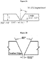
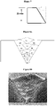
- a bevel for a pipe girth welding includes an opening (gap) that is about 3/32 of an inch to about 1/8 inch in height, as shown in Figure 2A .
- the opening can have a height (land) in a range of about 3/32 of an inch to about 1/8 inch.
- the bevel can have a bevel angle of about 30 degrees to about 37.5 degrees.
- the open bevel does not have a height, but rather the bevel starts from one surface of the base and proceeds substantially in a straight line to the other surface of the base, as shown in Figure 2B .
- the opening can be about 1/32 of an inch to about 6/32 of an inch wide (e.g., 5/32").
- the ER-HMS consumables have similar manganese content as the erosion resistant HMS base metal, which produces a weld metal microstructure similar to the base metal microstructure in that both are austenitic. This chemical compatibility prevents formation of martensitic phases at the weld metal/base metal interface. This reduces the risk of potential issues, such as cold cracking/hydrogen cracking.
- the high Mn steel base is as provided for and described in 2013 EM118, PCT/US2014/020599 entitled "Enhanced Wear Resistant Steel and Methods of Making the Same".
- the ER-HMS weld technology can help to in produce sound ER-HMS welds with the required properties.
- the viscous nature of the ER-HMS weld metals is overcome through the use of CO 2 in the shielding gas.
- the CO 2 in the shielding gas serves to improve weld pool fluidity, arc stability, and bead geometry including penetration profile. All of these attributes are important to avoid weld defects in pipeline welding.
- the use of CO 2 increases the oxygen potential and can increase oxygen content in the weld metal. Excessive formation of oxides in the weld metal can result in degraded toughness. Therefore, in an embodiment, the amount of CO 2 in the shielding gas is controlled between 10% and 30%.
- the ER-HMS weld technology applies a shielding gas with a composition of 80% Ar/20% CO 2 .
- the weld bead profiles of ER-HMS welds should be properly controlled to minimize risk of solidification cracking. In certain embodiments, highly concave bead profiles are avoided, as these are susceptible to solidification cracking.
- the bead profiles can be controlled with proper control of welding current, wire feed speed, and welding travel speed.
- cored wire consumables When using cored wire consumables to apply ER-HMS welds, it is important to avoid typical welding problems that can be associated with cored wire welding processes such as metal cored arc welding (MCAW) and flux cored arc welding (FCAW). Such potential problems include excessive spatter and weld metal porosity.
- MCAW metal cored arc welding
- FCAW flux cored arc welding
- Such potential problems include excessive spatter and weld metal porosity.
- CO 2 in the shielding gas, as described above can reduce spatter.
- Weld metal porosity can be reduced or avoided through proper cleaning practices, for example, the weld joint and consumable wire dry and clean, free from oil and other debris.
- Proper consumable wire storage practices should be followed, as cored wire consumables have a greater tendency than solid wire consumables to collect moisture when stored improperly.
- the welding process parameters can be controlled to produce a welding heat input that results in sound ER-HMS welds with suitable microstructures and properties for the slurry pipe application.
- the welding heat input should be high enough to enable consistent fusion at practical productivities for pipeline welding. It should be controlled, however, below a maximum of about 2.5 kJ/mm to ensure a weld that meets the requirements.
- Welding parameters current, voltage, and travel speed
- Welding parameters can be adjusted to ensure the welding heat input value is not exceeded. Excessive heat input beyond the maximum can result in a number of potential issues, including: solidification cracking, reduced weld metal toughness, and reduced base metal HAZ toughness.
- Welding heat input can be controlled below the maximum value to avoid producing large weld beads with high depth to width ratios that can be prone to solidification cracking. These high depth to width ratios can increase segregation in the weld metal and increase transverse strains in the girth weld joint, thus increasing the likelihood of solidification cracking.
- welding heat input control is key to maintaining the required toughness in the HMS base metal HAZ. It is understood that a heat input that is too high will result in excessive carbide precipitation on grain boundaries in the base metal HAZ. This can lead to local areas with reduced toughness. Welding heat input controlled below the maximum value results in a thermal cycle and cooling rate that produces a reduced amount of carbide precipitates at the HAZ grain boundaries. This improves the fracture toughness and resistance to cracking. Proper heat input control, therefore, is needed to ensure the required toughness is met in both the ER-HMS weld metal and the HMS base metal HAZ.
- ER-HMS welds Proper application of the weld metal chemistries, welding processes, and welding practices described above will produce suitable ER-HMS welds with microstructures and mechanical properties required to construct HMS slurry pipelines.
- the novel ER-HMS weld metal can be applied at practical productivities using modern pipeline welding equipment in both e.g., the 1G and 5G welding positions, and can also be applied to produce girth weld repair welds.
- An embodiment of the present disclosure comprises a method of producing ER-HMS welds for specific application requirements.
- the method comprises determining the desired ER-HMS weld metal chemistry within the effective ranges disclosed herein.
- the method includes determining the welding consumable wire chemistry given the base metal chemistry and the desired weld metal chemistry.
- determining the welding consumable wire chemistry comprises performing dilution calculations as discussed previously.
- the method further comprises welding the base metal using the welding consumable wire.
- welding the base metal includes controlling the arc stability and weld pool flow characteristics during welding to provide satisfactory weldability and weld fusion.
- ER-HMS weld metal chemistries can be designed for the application.
- the proper selection of consumable chemistries can be facilitated by screening using calculated material property predictions.
- Calculated phase diagrams can be used to predict key material properties over elemental concentration ranges.
- An example of this type of factorial design approach is eight variables (alloying elements) at three concentrations each, as is shown in Table 1, which gives 3 ⁇ 8 or 6,561 experimental conditions (compositions). Table 1.
- thermodynamic parameters can be calculated for each composition for purposes of initial screening.
- Three key parameters that can be used to predict ER-HMS weld metal performance are: (i) stacking fault energy, (ii) solidification temperature range, and (iii) cementite solvus temperature. The parameters were predicted with Thermo-Calc (Thermo-Calc Software AB, Sweden).
- SFE Stacking fault energy
- TRIP transformation induced plasticity
- TWIP twinning induced plasticity
- the specific active deformation mechanisms impact the strength and erosion performance of the weld metal.
- the SFE value is an important parameter in consumable alloy design because it is viewed as a strong predictor of tensile strength and erosion performance.
- the preferred ER-HMS weld metal SFE values are targeted to be similar to the base metal erosion resistant HMS SFE values (e.g., greater than 60 mJ/m 2 and less than 80 mJ/m 2 ).
- the solidification temperature range is the range between the liquidus temperature and the solidus temperature for a given alloy composition.
- the STR is a strong indicator of weldability as it is representative of the span of the mushy zone during solidification (weld metal solidification in this case).
- a higher value for STR correlates to a larger mushy zone and a higher susceptibility to weld solidification cracking.
- the ER-HMS weld metals solidify as primary austenite, which inherently makes them somewhat prone to weld solidification crack defects.
- the STR must be controlled to minimize solidification cracking susceptibility to allow for defect free pipeline girth welds.
- the preferred calculated STR values for the ER-HMS weld metal are targeted to be less than 120°C to provide the best performance.
- the cementite solvus temperature can be used to provide a relative estimate of carbide precipitation in the weld metal during solidification and multiple weld pass reheating. This temperature can be predicted based on alloy composition. The amount of carbide precipitation will be minimized when the CST is minimized. It is understood that excessive carbide precipitation in the weld metal will have a negative impact on weld metal toughness (a key mechanical property). As such, it is preferred that the ER-HMS weld metal composition produces a CST that is minimized.
- thermodynamic calculations of the key parameters described the most promising consumable chemistries were selected for further evaluation and development. Additionally, statistics describing the variation in key parameters with elemental variations were analyzed and trends identified regarding the effect of different elemental variations on calculated parameters.
- Figures 3, 4 , and 5 show plots representing the change in SFE, STR, and CST, respectively, as a function of the different alloying additions.
- the main effects come from variations in carbon, chromium, nickel, and nitrogen content.
- the statistical analysis of elemental effects on key parameters enabled selection of chemistry ranges for physical welding assessments (a much smaller set of chemistries than assessed with thermodynamic calculations).
- the chemistry ranges for ER-HMS consumables alloys for physical welding assessments can be selected based on best fit to the calculated thermodynamic criteria (SFE, STR, CST) that would allow a factorial experimental design.
- SFE, STR, CST calculated thermodynamic criteria
- the contents of several elements can be fixed, while four elements can be selected (carbon, manganese, molybdenum, and nickel) to vary between two values. This produces 2 4 or 16 experimental conditions. This can be supplemented with a subset of higher manganese consumables and a subset of consumables with some microalloying additions of titanium, niobium, tungsten, boron, and nitrogen.
- Table 2 shows a plot of the key thermodynamic parameters for these consumable chemistries.
- the experimental ER-HMS consumables were assessed by producing welds and testing mechanical properties, weldability, and erosion resistance.
- the ER-HMS assessment welds were made as butt welds (either of plate or of pipe) of erosion resistant HMS base metal.
- the butt welds were performed under the following MCAW conditions: an arc voltage of 26-30V, an arc current 140-180 A, at a wire feed of 250-300 ipm with a filler wire of 1.2 mm in diameter, shielding gas flow rate of 45 cfh with 80 Ar/20 CO 2 , and a heat inputs of 0.74-1.1 kJ/mm for both the root and fill passes.
- the novel ER-HMS weld metal can provide the required strength, toughness, and high erosion/corrosion resistance to join erosion resistant HMS slurry pipe through girth butt welding.
- the microstructures required to meet these property requirements are achieved through proper control of weld metal chemistry and welding process parameters.
- the ER-HMS weld metal must achieve the minimum tensile strength properties required for the application (slurry pipe). As such, it is desirable for the weld metal yield strength to be greater than the yield strength of the erosion resistant HMS base pipe or greater than the specified minimum yield strength (SMYS) required by the slurry pipeline design. Moreover, a weld metal ultimate tensile strength greater than the specified minimum ultimate tensile strength (SMUTS) for the base pipe body is also desirable. Furthermore, the weld metal should also provide some minimum specified level of tensile elongation.
- the ER-HMS weld metal can achieve each of these measurements because it is designed to contain a highly metastable austenite phase, which transforms into hard ⁇ '-martensite and undergoes microtwinning upon straining. Additionally, the solid solution strengthening elements in the weld metal (e.g., molybdenum) provide additional strengthening by disrupting lattice dislocation motion. The combination of these strengthening mechanisms provides a high strength and work hardening rate that achieves the tensile strength requirements for girth welds of typical slurry pipelines.
- tested ER-HMS weld metal properties are shown in Table 4 and compared to girth weld requirements for API X70 grade based pipeline design (SMYS is 570 MPa (70 ksi)).
- the welds were performed with a mechanized MCAW under the following conditions: 80 Ar/20 CO 2 shielding gas as a flow rate of 40-50 cfh, arc voltage of 20-22 V for roots and 20-31 V for fills, an arc current of 150-190 A for roots and 210-265 A for fills, a filler wire having a diameter of 1.2 mm, a wire feed of 230 ipm for the root and 330-440 ipm for fills, and heat input of 0.86-1.02 kJ/mm for roots and 0.6-0.93 kJ/mm for fills.
- the API X70 grade design is common for oil sands slurry pipeline design. Modifications to ER-HMS weld metal chemistry can be made within the ranges disclosed here to achieve the required weld metal tensile properties for a range of potential slurry pipeline grades, including X52, X60, X65, X70, and X80.
- the ER-HMS weld metal demonstrates markedly higher toughness measurements than is required for slurry pipe applications. Table 4. Tested ER-HMS weld metal properties compared to girth weld property requirements for a typical API X70 grade based slurry pipeline design.
- the ER-HMS weld metal must achieve minimum toughness properties required for the application (slurry pipe).
- the base metal near the weld (the HAZ) of the present disclosure can also achieve these minimum toughness properties.
- the most common assessment of toughness for this application is impact toughness measured by conducting Charpy V-notch (CVN) tests of the weld metal and several regions of the HAZ.
- the test values reported in units of energy (i.e., joules, J), must be greater than the minimum required CVN as specified by the design code for the application.
- the ER-HMS welds achieve the requirements in both the weld metal and the erosion resistant HMS base metal HAZ.
- the weld metal toughness is achieved with a weld metal microstructure consisting of austenite phase and a limited amount of carbides, which results in a ductile fracture mode.
- the base metal HAZ toughness can be achieved by controlling welding heat input such that carbide precipitation in the HAZ is minimized. High heat inputs can lead to excessive carbide precipitation at HAZ grain boundaries and increased hardness in the HAZ, leading to inadequate CVN toughness values.
- An example of the CVN values achieved with produced ER-HMS welds is shown in Table 4 and compared to weld impact toughness requirements for slurry pipe application.
- Figure 9 is a plot that illustrates the average yield strength and average CVN values for candidate HMS girth welding consumable as performed under the conditions described above and with the compositions as shown in Table 3.
- the target ranges of a minimum yield strength of 3344 MPa (485 ksi) and minimum CVN energy of 27 J are shown within the shaded region labeled target.
- Welds FX-5, FX-8, FX-14, and FX-16 met the target ranges, while welds FX-1, FX-9, FX-11, FX-17 did not meet the target ranges.
- the ER-HMS weld metal of the present disclosure achieves similar erosion/corrosion resistance compared to the erosion resistant HMS pipe body.
- the ER-HMS is a viable option to join HMS slurry pipe sections.
- the inner wall of the pipe and thus the root surface of the girth weld are exposed to the erosive/corrosive operating slurry environment.
- the weld metal must have similar resistance to erosion/corrosion degradation as the base metal in order to achieve the maximum operating benefits of improved erosion / corrosion performance in the HMS base metal. Faster degradation rates in the welds would lead to replacement of the slurry pipe prior to full utilization of the available lifetime in the base metal pipe.
- erosion /corrosion performance is conducted by conducting separate erosion and corrosion tests and conducting field tests to expose the ER-HMS weld metal to the actual field conditions.
- the preferred test for erosion performance is the jet impingement test, which involves directing a high velocity water and sand mixture at the sample surface for a prescribed rate and duration and measuring the amount of material that is lost.
- the jet impingement test is seen as providing a general indication of relative erosion resistance.
- the coupons can be exposed to an aqueous environment that simulates a specific slurry pipeline corrosive environment, typically containing chlorides and dissolved oxygen. Coupons can be exposed for a 30 day test duration, after which they are removed from the environment and analyzed to assess performance.
- the overall weight loss of the coupons can be used to determine a general corrosion rate, and the post-test surface profile can be measured to determine depths of corrosion penetration in both the weld metal region and the base metal region.
- Corrosion coupon testing of ER-HMS test welds in a representative aqueous slurry pipeline environment resulted in weight loss corrosion rates between 20 and 25 mils per year (mpy) and similar average depths of penetration in both the weld metal and base metal.
- the levels of erosion and corrosion resistance exhibited by the ER-HMS weld metal are sufficient for joining erosion resistance HMS pipe for the slurry pipeline application.
- the novel ER-HMS weld metal can provide the required weldability to join erosion resistant HMS slurry pipe through girth butt welding. This weldability is achieved through proper control of weld metal chemistry, welding process parameters, and/or welding joint design.
- Solidification cracking susceptibility can be assessed using the trans-varestraint test. This test assesses solidification cracking susceptibility for weld metal by applying strain to solidifying weld metal to determine strain - cracking relationships.
- a key output of the trans-varestraint test is the solidification cracking temperature range (SCTR).
- SCTR solidification cracking temperature range
- a larger SCTR value typically represents a higher susceptibility to solidification cracking.
- the SCTR values at 5% strain and 7% strain are shown for several ER-HMS consumables in Table 5.
- the Gas Tungsten Arc Welding was performed under the following conditions: an arc voltage of 11.6 V, an arc current of 180 A, a travel speed of 2.54 mm/second, a heat input of 1.37 kJ/mm, and a cooling rate in solification range of approximately 125°C/second.
- the calculated SCTR values range from about 40°C to about 160°C. These values are similar to reported values for stainless steels that solidify as primary austenite (Welding Metallurgy and Weldability, Lippold, John C., 2014). This indicates that ER-HMS weld metals can be produced without solidification cracking.
- the weld metal has a SCTR value in a range of about 40°C to about 160°C.
- Figure 11 illustrates the average maximum crack distance (MCD) (mm) values at 1% strain to 7% strain for several reference ER-HMS consumable. Table 5. Trans-varestraint test results for several ER-HMS consumables , for comparison only. Consumable # Calculated STR SCTR (°C) at 5% strain SCTR (°C) at 7% strain FX-1 93.3 64 90 FX-5 123.9 152 131 FX-8 128.6 118 159 FX-11 92.5 53 53 FX-14 144.7 94 117 FX-16 148.5 84 125 FX-17 90.5 44 43 FX-20 108.4 87 103
- Figure 12 illustrates an exemplary weld bead sequence for the ER-HMS weld according to a reference embodiment not forming part of the invention, with an open bevel, as shown in Figure 2A .
- An example of a ER-HMS weld macro produced in this embodiment is shown in Figure 13
- an example of an optical micrograph of the ER-HMS weld metal is shown in Figure 14 .
- Table 6 is a summary of ASME Section IX test results from 1G pipe girth weld applied as described with regard to Figures 2A and 10-12 .
- Mechanized MCAW was performed under the following conditions: 80 Ar/20 CO 2 shielding gas as a flow rate of 50 cfh, arc voltage of 20-22 V for roots and 24-31 V for fills, an arc current of 150-165 A for roots and 210-265 A for fills, a filler wire having a diameter of 1.2 mm, a wire feed of 230 ipm for the root and 296-441 ipm for fills, and heat input of 0.9-1.02 kJ/mm for roots and 0.6-0.93 kJ/mm for fills. Table 6.
- the embodiment described above can produce ER-HMS welds that satisfy the requirements for fabricating and applying erosion resistant HMS slurry pipelines.
- the welds produced during welding procedure qualification were tested.
- the ER-HMS weld metal properties from these welds are shown in Table 7 and compared to ASME Section IX girth weld requirements for API X70 grade based pipeline design (SMYS is 483 MPa (70 ksi)).
- Mechanized MCAW was performed under the following conditions: 80 Ar/20 CO 2 shielding gas as a flow rate of 50 cfh, arc voltage of 20-22 V for roots and 24-31 V for fills, an arc current of 150-165 A for roots and 210-265 A for fills, a filler wire having a diameter of 1.2 mm, a wire feed of 230 ipm for the root and 296-441 ipm for fills, and heat input of 0.9-1.02 kJ/mm for roots and 0.6-0.93 kJ/mm for fills.
- the produced ER-HMS welds demonstrated superior toughness performance relative to the requirements. Table 7.
- Figure 15 is an example of a weld bead sequence for pipe girth welds (for example, 1G pipe) for a bevel, as shown in Figure 2B .
- Figure 16 illustrates the locations of points within Table 8, which underwent Vickers hardness test.
- Mechanized MCAW was performed under the following conditions: 80 Ar/20 CO 2 shielding gas as a flow rate of 50 cfh, arc voltage of 20-22 V for roots and 24-31 V for fills, an arc current of 150-165 A for roots and 210-265 A for fills, a filler wire having a diameter of 1.2 mm, a wire feed of 230 ipm for the root and 296-441 ipm for fills, and heat input of 0.9-1.02 kJ/mm for roots and 0.6-0.93 kJ/mm for fills. Vickers hardness test provides a wide hardness scale that is easily performed.
- Vickers Pyramid Number is the measure of hardness of the Vickers hardness test and is determined by the load over the surface area of the indentation.
- Table 8 summarizes the Vickers hardness test results for points from a FX-5 1G pipe girth weld. Table 8. Summary of Vickers hardness test results from a FX-5 1G pipe girth weld.
Claims (13)
- Composition de soudage pour des métaux de base en acier à haute teneur en manganèse, ladite composition comprenant:carbone dans une gamme de 0,4 % à 0,8 % en poids;manganèse dans une gamme de 18 % à 24 % en poids;chrome dans une gamme de 1 % à 6 % en poids;titane dans une gamme de 1 % à 2 % en poids;molybdène dans une gamme de 1 % à 4 % en poids;nickel en quantité ≤ 5 % en poids;silicium dans une quantité de 0,4 % à 1,0 % en poids;soufre en quantité ≤ 200 ppm;phosphore en quantité ≤ 200 ppm;et un reste qui est du fer,ladite composition comprenant facultativementniobium en quantité ≤ 5 % en poids;tungstène en quantité ≤ 5 % en poids;aluminium en quantité ≤ 1,0 % en poids;bore en quantité ≤ 0,1 % en poids;azote en quantité ≤ 1,5 % en poids; ouune combinaison de ceux-ci;et dans laquelle la composition a une microstructure austénitique.
- Composition selon la revendication 1, dans laquelle la microstructure austénitique se transforme en a'-martensite dure et subit une formation de microjointures sous l'effet d'une charge.
- Système pour fournir des joints soudés à haute teneur en manganèse résistant à l'érosion/la corrosion, le système comprenant : un fil-électrode consommable qui produit une soudure comprenant :carbone dans une gamme de 0,4 % en poids à 0,8 % en poids, manganèse dans une gamme de 18 % en poids à 24 % en poids, chrome dans une gamme de 1 % en poids à 6 % en poids, titane dans une gamme de 1 % en poids à 2 % en poids, molybdène dans une gamme de 1 % en poids à 4 % en poids, nickel en quantité ≤ 5 % en poids, silicium dans une quantité de 0,4 % en poids à 1,0 % en poids.%, soufre en quantité ≤ 200 ppm, phosphore en quantité ≤ 200 ppm, et un reste qui est du fer, dans lequel la soudure a une microstructure austénitique ; et dans lequel la soudure comprend facultativement niobium en quantité ≤ 5 % en poids, tungstène en quantité ≤ 5 % en poids, aluminium en quantité ≤ 1,0 % en poids, bore en quantité ≤ 0,1 % en poids, azote en quantité ≤ 1,5 % en poids ;et une source d'énergie de soudage sous gaz de protection métallique qui effectue un soudage sous gaz de protection, dans lequel la source d'énergie de soudage sous gaz de protection métallique produit un apport de chaleur de soudage ne dépassant pas 2,5 kJ/mm.
- Système selon la revendication 3, dans lequel l'apport de chaleur de soudage se situe dans une gamme de 0,6 à 1,0 kJ/mm.
- Système selon la revendication 3 ou 4, comprenant en outre un dispositif pour fournir au moins un gaz de protection, dans lequel ledit au moins un gaz de protection contient du CO2 dans une gamme de 10% à 30%.
- Système selon la revendication 5, dans lequel ledit au moins un gaz de protection comprend 80% d'argon et 20% de CO2.
- Procédé de fabrication d'un métal d'apport à haute teneur en Mn résistant à l'érosion/la corrosion, le procédé comprenant :fournir au moins deux supports en acier à haute teneur en Mn à souder, et une soudure comprenant carbone dans une gamme de 0,4 % en poids à 0,8 % en poids, manganèse dans une gamme de 18 % en poids à 24 % en poids, chrome dans une gamme de 1 % à 6 % en poids, titane dans une gamme de 1 % à 2 % en poids, molybdène dans une gamme de 1 % à 4 % en poids, nickel en quantité ≤ 5 % en poids, silicium dans une quantité de 0,4 % à 1,0 % en poids, soufre en quantité ≤ 200 ppm, phosphore en quantité ≤ 200 ppm, et un reste qui est du fer, dans lequel la soudure a une microstructure austénitique; et dans lequel la soudure comprend éventuellement niobium en quantité ≤ 5 % en poids, tungstène en quantité ≤ 5 % en poids, aluminium en quantité ≤ 1,0 % en poids, bore en quantité ≤ 0,1 % en poids, azote en quantité ≤ 1,5 % en poids ;et faire fondre et refroidir le matériau d'apport pour créer un métal d'apport.
- Procédé selon la revendication 7, dans lequel la soudure fournit un apport de chaleur de soudage ne dépassant pas 2,5 kJ/mm dans le matériau d'apport.
- Procédé selon la revendication 7 ou 8, dans lequel les au moins deux supports en acier à haute teneur en Mn comprennent une zone à souder, les zones ayant des pentes de 30 degrés à 37,5 degrés.
- Procédé selon l'une des revendications 7 à 9, dans lequel au moins l'un des points suivants s'applique: le dépôt de soudure a, à l'état soudé, une limite d'élasticité supérieure à une limite d'élasticité d'un support en acier à haute teneur en manganèse ou supérieure à une limite d'élasticité minimale requise; le métal d'apport a, à l'état soudé, une limite d'élasticité supérieure à 70 ksi (483 MPa); le métal d'apport a, à l'état soudé, une résistance finale à la traction supérieure à 82,7 ksi (570 MPa); le métal d'apport a, à l'état soudé, un allongement à la traction supérieur à 16%; le métal d'apport a, à l'état soudé, une plage de température de fissuration par solidification de 40°C à 170°C pour une charge de 7% ; ou une combinaison de ceux-ci.
- Procédé selon l'une quelconque des revendications 7 à 10, dans lequel le métal d'apport et/ou une zone affectée thermiquement des supports ont, à l'état soudé, une énergie CVN (Charpy V-enoches) à 29°C supérieure à 27 J.
- Procédé selon l'une quelconque des revendications 7 à 11, dans lequel le métal de base est un acier à haute teneur en Mn résistant à l'érosion/la corrosion.
- Procédé selon l'une quelconque des revendications 7 à 12, comprenant en outre, une limitation d'une dilution de carbone dans le métal de soudage à partir du métal de base.
Applications Claiming Priority (2)
| Application Number | Priority Date | Filing Date | Title |
|---|---|---|---|
| US201662330415P | 2016-05-02 | 2016-05-02 | |
| PCT/US2017/030686 WO2017192619A1 (fr) | 2016-05-02 | 2017-05-02 | Technologie de soudage d'entretoises sur le terrain pour conduites de boues d'acier à teneur élevée en manganèse |
Publications (3)
| Publication Number | Publication Date |
|---|---|
| EP3452247A1 EP3452247A1 (fr) | 2019-03-13 |
| EP3452247A4 EP3452247A4 (fr) | 2019-12-04 |
| EP3452247B1 true EP3452247B1 (fr) | 2022-07-06 |
Family
ID=60203291
Family Applications (1)
| Application Number | Title | Priority Date | Filing Date |
|---|---|---|---|
| EP17793185.4A Active EP3452247B1 (fr) | 2016-05-02 | 2017-05-02 | Technologie de soudage d'entretoises sur le terrain pour conduites de boues d'acier à teneur élevée en manganèse |
Country Status (11)
| Country | Link |
|---|---|
| US (2) | US10493569B2 (fr) |
| EP (1) | EP3452247B1 (fr) |
| JP (2) | JP2019520473A (fr) |
| KR (1) | KR102266804B1 (fr) |
| CN (1) | CN109070284A (fr) |
| AR (1) | AR108269A1 (fr) |
| AU (1) | AU2017259978A1 (fr) |
| BR (1) | BR112018071995A2 (fr) |
| CA (1) | CA3022962A1 (fr) |
| RU (1) | RU2018141292A (fr) |
| WO (1) | WO2017192619A1 (fr) |
Families Citing this family (13)
| Publication number | Priority date | Publication date | Assignee | Title |
|---|---|---|---|---|
| US10947610B2 (en) | 2018-08-21 | 2021-03-16 | Exxonmobil Upstream Research Company | Mooring chains comprising high manganese steels and associated methods |
| SG11202101711UA (en) * | 2018-08-23 | 2021-03-30 | Jfe Steel Corp | Solid wire for gas metal arc welding |
| CN110016621B (zh) * | 2019-03-15 | 2020-11-13 | 中南大学 | 一种粉末冶金高锰奥氏体无磁钢及制备方法 |
| JP6978615B2 (ja) * | 2019-03-29 | 2021-12-08 | Jfeスチール株式会社 | Tig溶接用溶加材 |
| JP6978613B2 (ja) * | 2019-03-29 | 2021-12-08 | Jfeスチール株式会社 | 極低温用高強度溶接継手の製造方法 |
| JP6978614B2 (ja) * | 2019-03-29 | 2021-12-08 | Jfeスチール株式会社 | ガスメタルアーク溶接用ソリッドワイヤおよびガスメタルアーク溶接方法 |
| KR102321317B1 (ko) * | 2019-10-16 | 2021-11-02 | 주식회사 포스코 | 용접봉용 선재 및 이의 제조방법 |
| JP7319729B2 (ja) * | 2020-09-23 | 2023-08-02 | 株式会社ユニバーサルエンターテインメント | 遊技機 |
| KR20230130122A (ko) * | 2021-03-01 | 2023-09-11 | 제이에프이 스틸 가부시키가이샤 | Tig 용접 이음매 |
| US20240051070A1 (en) * | 2021-03-01 | 2024-02-15 | Jfe Steel Corporation | Submerged arc welded joint |
| WO2022221803A1 (fr) | 2021-04-12 | 2022-10-20 | Exxonmobil Upstream Research Company | Procédé et système d'évaluation d'inspection de soudures de tuyaux au moyen d'un essai par radiographie |
| WO2023026763A1 (fr) * | 2021-08-26 | 2023-03-02 | Jfeスチール株式会社 | Fil à âme métallique pour soudage à l'arc submergé et procédé de soudage à l'arc submergé l'utilisant |
| CN116079278B (zh) * | 2023-04-06 | 2023-12-08 | 中国科学院合肥物质科学研究院 | 一种高吸能高锰钢实心焊丝及其焊接工艺 |
Family Cites Families (22)
| Publication number | Priority date | Publication date | Assignee | Title |
|---|---|---|---|---|
| US3716691A (en) * | 1971-04-27 | 1973-02-13 | Allegheny Ludlum Ind Inc | Shielded arc welding with austenitic stainless steel |
| JPS5126132B2 (fr) * | 1972-09-25 | 1976-08-04 | ||
| US4017711A (en) * | 1972-09-25 | 1977-04-12 | Nippon Steel Corporation | Welding material for low temperature steels |
| TW387832B (en) * | 1997-06-20 | 2000-04-21 | Exxon Production Research Co | Welding methods for producing ultra-high strength weldments with weld metalshaving excellent cryogenic temperature practure toughness |
| GC0000233A (en) * | 2000-08-07 | 2006-03-29 | Exxonmobil Upstream Res Co | Weld metals with superior low temperature toughness for joining high strength, low alloy steels |
| US7562807B2 (en) * | 2004-05-05 | 2009-07-21 | Electric Power Research Institute | Weld filler for welding dissimilar alloy steels and method of using same |
| JP5463527B2 (ja) * | 2008-12-18 | 2014-04-09 | 独立行政法人日本原子力研究開発機構 | オーステナイト系ステンレス鋼からなる溶接材料およびそれを用いた応力腐食割れ予防保全方法ならびに粒界腐食予防保全方法 |
| KR101271974B1 (ko) * | 2010-11-19 | 2013-06-07 | 주식회사 포스코 | 극저온 인성이 우수한 고강도 강재 및 그 제조방법 |
| US20120160363A1 (en) * | 2010-12-28 | 2012-06-28 | Exxonmobil Research And Engineering Company | High manganese containing steels for oil, gas and petrochemical applications |
| CN102218622B (zh) * | 2011-06-03 | 2013-09-11 | 甘肃省机械科学研究院 | 一种高锰钢堆焊实芯焊丝及其制造方法 |
| JP5469648B2 (ja) | 2011-11-10 | 2014-04-16 | 株式会社神戸製鋼所 | 極低温用鋼用溶接材料 |
| KR101372599B1 (ko) * | 2012-07-09 | 2014-03-10 | 주식회사 포스코 | 내마모성이 우수한 고망간강용 용접이음부 |
| CN104508165A (zh) * | 2012-07-27 | 2015-04-08 | 埃克森美孚上游研究公司 | 用于苛刻的结构应用的高强度钢焊接金属 |
| CN104797730B (zh) * | 2012-11-22 | 2017-03-08 | Posco公司 | 极低温钢的焊接接头及用于制造该焊接接头的焊接材料 |
| US20140261918A1 (en) * | 2013-03-15 | 2014-09-18 | Exxonmobil Research And Engineering Company | Enhanced wear resistant steel and methods of making the same |
| CN105813799B (zh) * | 2013-12-06 | 2019-06-07 | Posco公司 | 极低温冲击韧性优异的高强度焊接接头及用于其的电弧焊接用药芯焊丝 |
| KR20150066373A (ko) * | 2013-12-06 | 2015-06-16 | 주식회사 포스코 | 내충격성 및 내마모성이 우수한 용접이음부 |
| KR20150066369A (ko) * | 2013-12-06 | 2015-06-16 | 주식회사 포스코 | 내충격성 및 내마모성이 우수한 플럭스코어드 아크 용접재료 |
| KR20150066372A (ko) * | 2013-12-06 | 2015-06-16 | 주식회사 포스코 | 내충격성 및 내마모성이 우수한 서브머지드아크용접 및 가스금속아크용접용 용접재료 |
| CN103785924A (zh) * | 2014-01-21 | 2014-05-14 | 首钢总公司 | 一种高锰钢铸钢辙叉及钢轨堆焊修复方法 |
| KR101568642B1 (ko) | 2015-09-07 | 2015-11-12 | 주식회사 포스코 | 내충격성 및 내마모성이 우수한 서브머지드아크용접 및 가스금속아크용접용 용접재료 |
| CN105234583A (zh) * | 2015-10-26 | 2016-01-13 | 钢铁研究总院 | 一种适用于煤制气管道焊接的x80埋弧焊焊丝 |
-
2017
- 2017-05-02 CA CA3022962A patent/CA3022962A1/fr active Pending
- 2017-05-02 AR ARP170101117A patent/AR108269A1/es unknown
- 2017-05-02 AU AU2017259978A patent/AU2017259978A1/en not_active Abandoned
- 2017-05-02 KR KR1020187034826A patent/KR102266804B1/ko active IP Right Grant
- 2017-05-02 EP EP17793185.4A patent/EP3452247B1/fr active Active
- 2017-05-02 JP JP2018557344A patent/JP2019520473A/ja active Pending
- 2017-05-02 US US15/584,794 patent/US10493569B2/en active Active
- 2017-05-02 CN CN201780027293.4A patent/CN109070284A/zh active Pending
- 2017-05-02 BR BR112018071995-1A patent/BR112018071995A2/pt not_active IP Right Cessation
- 2017-05-02 WO PCT/US2017/030686 patent/WO2017192619A1/fr unknown
- 2017-05-02 RU RU2018141292A patent/RU2018141292A/ru not_active Application Discontinuation
-
2019
- 2019-10-31 US US16/670,494 patent/US20200086431A1/en active Pending
-
2022
- 2022-03-15 JP JP2022040664A patent/JP2022081631A/ja active Pending
Also Published As
| Publication number | Publication date |
|---|---|
| AR108269A1 (es) | 2018-08-01 |
| JP2022081631A (ja) | 2022-05-31 |
| RU2018141292A3 (fr) | 2020-08-11 |
| WO2017192619A1 (fr) | 2017-11-09 |
| KR20180132960A (ko) | 2018-12-12 |
| US20200086431A1 (en) | 2020-03-19 |
| US20180021895A1 (en) | 2018-01-25 |
| US10493569B2 (en) | 2019-12-03 |
| CN109070284A (zh) | 2018-12-21 |
| BR112018071995A2 (pt) | 2019-02-12 |
| RU2018141292A (ru) | 2020-06-03 |
| CA3022962A1 (fr) | 2017-11-09 |
| AU2017259978A1 (en) | 2018-10-25 |
| JP2019520473A (ja) | 2019-07-18 |
| EP3452247A1 (fr) | 2019-03-13 |
| EP3452247A4 (fr) | 2019-12-04 |
| KR102266804B1 (ko) | 2021-06-22 |
Similar Documents
| Publication | Publication Date | Title |
|---|---|---|
| EP3452247B1 (fr) | Technologie de soudage d'entretoises sur le terrain pour conduites de boues d'acier à teneur élevée en manganèse | |
| EP3452248B1 (fr) | Technologie de soudage de métaux dissemblables sur le terrain pour acier à teneur élevée en manganèse résistant à l'usure perfectionné | |
| US11883906B2 (en) | High manganese steel pipe with step-out weld zone erosion-corrosion resistance and method of making the same | |
| Jebaraj et al. | Weldability, machinability and surfacing of commercial duplex stainless steel AISI2205 for marine applications–A recent review | |
| Saha et al. | A review on different cladding techniques employed to resist corrosion | |
| US10086462B2 (en) | Hardfacing with low carbon steel electrode | |
| Alvaraes et al. | Microstructural characterization of Inconel 625 nickel-based alloy weld cladding obtained by electroslag welding process | |
| Jorge et al. | Evaluation of the AISI 904L alloy weld overlays obtained by GMAW and electro-slag welding processes | |
| Yue et al. | Welding technology development for an erosion-resistant slurry pipeline steel | |
| Gajvoronsky et al. | Influence of deposited metal composition on structure and mechanical properties of reconditioned railway wheels | |
| US20240157486A1 (en) | Methods of welding high manganese steel with step-out weld zone erosion-corrosion resistance | |
| Mellor | Welding surface treatment methods for protection against wear | |
| Goswami et al. | Traditions in hardfacing technology and wear resistance-2 | |
| White | Welding of Cast Irons | |
| Natsume et al. | Practical applications of MIG and TIG weld surfacing |
Legal Events
| Date | Code | Title | Description |
|---|---|---|---|
| STAA | Information on the status of an ep patent application or granted ep patent |
Free format text: STATUS: THE INTERNATIONAL PUBLICATION HAS BEEN MADE |
|
| PUAI | Public reference made under article 153(3) epc to a published international application that has entered the european phase |
Free format text: ORIGINAL CODE: 0009012 |
|
| STAA | Information on the status of an ep patent application or granted ep patent |
Free format text: STATUS: REQUEST FOR EXAMINATION WAS MADE |
|
| 17P | Request for examination filed |
Effective date: 20181112 |
|
| AK | Designated contracting states |
Kind code of ref document: A1 Designated state(s): AL AT BE BG CH CY CZ DE DK EE ES FI FR GB GR HR HU IE IS IT LI LT LU LV MC MK MT NL NO PL PT RO RS SE SI SK SM TR |
|
| AX | Request for extension of the european patent |
Extension state: BA ME |
|
| DAV | Request for validation of the european patent (deleted) | ||
| DAX | Request for extension of the european patent (deleted) | ||
| A4 | Supplementary search report drawn up and despatched |
Effective date: 20191107 |
|
| RIC1 | Information provided on ipc code assigned before grant |
Ipc: C22C 38/22 20060101ALI20191031BHEP Ipc: B23K 9/025 20060101ALI20191031BHEP Ipc: B23K 9/16 20060101AFI20191031BHEP Ipc: B23K 9/09 20060101ALI20191031BHEP Ipc: C22C 38/50 20060101ALI20191031BHEP Ipc: B23K 9/23 20060101ALI20191031BHEP Ipc: B23K 103/04 20060101ALN20191031BHEP Ipc: C22C 38/44 20060101ALI20191031BHEP Ipc: B23K 35/02 20060101ALI20191031BHEP Ipc: C22C 38/38 20060101ALI20191031BHEP Ipc: C22C 38/48 20060101ALI20191031BHEP Ipc: C22C 38/58 20060101ALI20191031BHEP Ipc: B23K 35/30 20060101ALI20191031BHEP Ipc: C22C 38/02 20060101ALI20191031BHEP Ipc: B23K 101/10 20060101ALI20191031BHEP Ipc: B23K 9/173 20060101ALI20191031BHEP Ipc: B23K 35/38 20060101ALI20191031BHEP |
|
| RAP1 | Party data changed (applicant data changed or rights of an application transferred) |
Owner name: EXXONMOBIL RESEARCH AND ENGINEERING COMPANY Owner name: POSCO |
|
| STAA | Information on the status of an ep patent application or granted ep patent |
Free format text: STATUS: EXAMINATION IS IN PROGRESS |
|
| STAA | Information on the status of an ep patent application or granted ep patent |
Free format text: STATUS: EXAMINATION IS IN PROGRESS |
|
| 17Q | First examination report despatched |
Effective date: 20201014 |
|
| STAA | Information on the status of an ep patent application or granted ep patent |
Free format text: STATUS: EXAMINATION IS IN PROGRESS |
|
| REG | Reference to a national code |
Ref country code: DE Ref legal event code: R079 Ref document number: 602017059285 Country of ref document: DE Free format text: PREVIOUS MAIN CLASS: B23K0035300000 Ipc: B23K0009160000 |
|
| GRAP | Despatch of communication of intention to grant a patent |
Free format text: ORIGINAL CODE: EPIDOSNIGR1 |
|
| STAA | Information on the status of an ep patent application or granted ep patent |
Free format text: STATUS: GRANT OF PATENT IS INTENDED |
|
| RIC1 | Information provided on ipc code assigned before grant |
Ipc: B23K 103/04 20060101ALN20211220BHEP Ipc: B23K 35/02 20060101ALI20211220BHEP Ipc: B23K 9/23 20060101ALI20211220BHEP Ipc: B23K 9/173 20060101ALI20211220BHEP Ipc: B23K 9/09 20060101ALI20211220BHEP Ipc: B23K 9/025 20060101ALI20211220BHEP Ipc: B23K 101/10 20060101ALI20211220BHEP Ipc: B23K 35/38 20060101ALI20211220BHEP Ipc: C22C 38/38 20060101ALI20211220BHEP Ipc: C22C 38/58 20060101ALI20211220BHEP Ipc: C22C 38/50 20060101ALI20211220BHEP Ipc: C22C 38/48 20060101ALI20211220BHEP Ipc: C22C 38/44 20060101ALI20211220BHEP Ipc: C22C 38/22 20060101ALI20211220BHEP Ipc: C22C 38/02 20060101ALI20211220BHEP Ipc: B23K 35/30 20060101ALI20211220BHEP Ipc: B23K 9/16 20060101AFI20211220BHEP |
|
| INTG | Intention to grant announced |
Effective date: 20220119 |
|
| GRAS | Grant fee paid |
Free format text: ORIGINAL CODE: EPIDOSNIGR3 |
|
| GRAA | (expected) grant |
Free format text: ORIGINAL CODE: 0009210 |
|
| STAA | Information on the status of an ep patent application or granted ep patent |
Free format text: STATUS: THE PATENT HAS BEEN GRANTED |
|
| AK | Designated contracting states |
Kind code of ref document: B1 Designated state(s): AL AT BE BG CH CY CZ DE DK EE ES FI FR GB GR HR HU IE IS IT LI LT LU LV MC MK MT NL NO PL PT RO RS SE SI SK SM TR |
|
| RAP3 | Party data changed (applicant data changed or rights of an application transferred) |
Owner name: POSCO Owner name: EXXONMOBIL TECHNOLOGY AND ENGINEERING COMPANY |
|
| REG | Reference to a national code |
Ref country code: AT Ref legal event code: REF Ref document number: 1502522 Country of ref document: AT Kind code of ref document: T Effective date: 20220715 Ref country code: CH Ref legal event code: EP |
|
| REG | Reference to a national code |
Ref country code: DE Ref legal event code: R096 Ref document number: 602017059285 Country of ref document: DE |
|
| REG | Reference to a national code |
Ref country code: IE Ref legal event code: FG4D |
|
| RAP2 | Party data changed (patent owner data changed or rights of a patent transferred) |
Owner name: POSCO |
|
| REG | Reference to a national code |
Ref country code: LT Ref legal event code: MG9D |
|
| REG | Reference to a national code |
Ref country code: NL Ref legal event code: MP Effective date: 20220706 |
|
| REG | Reference to a national code |
Ref country code: BE Ref legal event code: PD Owner name: POSCO; KR Free format text: DETAILS ASSIGNMENT: CHANGE OF OWNER(S), ASSIGNMENT; FORMER OWNER NAME: POSCO Effective date: 20220920 |
|
| PG25 | Lapsed in a contracting state [announced via postgrant information from national office to epo] |
Ref country code: SE Free format text: LAPSE BECAUSE OF FAILURE TO SUBMIT A TRANSLATION OF THE DESCRIPTION OR TO PAY THE FEE WITHIN THE PRESCRIBED TIME-LIMIT Effective date: 20220706 Ref country code: RS Free format text: LAPSE BECAUSE OF FAILURE TO SUBMIT A TRANSLATION OF THE DESCRIPTION OR TO PAY THE FEE WITHIN THE PRESCRIBED TIME-LIMIT Effective date: 20220706 Ref country code: PT Free format text: LAPSE BECAUSE OF FAILURE TO SUBMIT A TRANSLATION OF THE DESCRIPTION OR TO PAY THE FEE WITHIN THE PRESCRIBED TIME-LIMIT Effective date: 20221107 Ref country code: NO Free format text: LAPSE BECAUSE OF FAILURE TO SUBMIT A TRANSLATION OF THE DESCRIPTION OR TO PAY THE FEE WITHIN THE PRESCRIBED TIME-LIMIT Effective date: 20221006 Ref country code: NL Free format text: LAPSE BECAUSE OF FAILURE TO SUBMIT A TRANSLATION OF THE DESCRIPTION OR TO PAY THE FEE WITHIN THE PRESCRIBED TIME-LIMIT Effective date: 20220706 Ref country code: LV Free format text: LAPSE BECAUSE OF FAILURE TO SUBMIT A TRANSLATION OF THE DESCRIPTION OR TO PAY THE FEE WITHIN THE PRESCRIBED TIME-LIMIT Effective date: 20220706 Ref country code: LT Free format text: LAPSE BECAUSE OF FAILURE TO SUBMIT A TRANSLATION OF THE DESCRIPTION OR TO PAY THE FEE WITHIN THE PRESCRIBED TIME-LIMIT Effective date: 20220706 Ref country code: FI Free format text: LAPSE BECAUSE OF FAILURE TO SUBMIT A TRANSLATION OF THE DESCRIPTION OR TO PAY THE FEE WITHIN THE PRESCRIBED TIME-LIMIT Effective date: 20220706 Ref country code: ES Free format text: LAPSE BECAUSE OF FAILURE TO SUBMIT A TRANSLATION OF THE DESCRIPTION OR TO PAY THE FEE WITHIN THE PRESCRIBED TIME-LIMIT Effective date: 20220706 |
|
| REG | Reference to a national code |
Ref country code: AT Ref legal event code: MK05 Ref document number: 1502522 Country of ref document: AT Kind code of ref document: T Effective date: 20220706 |
|
| REG | Reference to a national code |
Ref country code: DE Ref legal event code: R081 Ref document number: 602017059285 Country of ref document: DE Owner name: POSCO CO., LTD, POHANG-SI, KR Free format text: FORMER OWNERS: EXXONMOBIL TECHNOLOGY AND ENGINEERING COMPANY, SPRING, TX, US; POSCO, POHANG-SI, GYEONGSANGBUK-DO, KR Ref country code: DE Ref legal event code: R081 Ref document number: 602017059285 Country of ref document: DE Owner name: POSCO CO., LTD, POHANG- SI, KR Free format text: FORMER OWNERS: EXXONMOBIL TECHNOLOGY AND ENGINEERING COMPANY, SPRING, TX, US; POSCO, POHANG-SI, GYEONGSANGBUK-DO, KR Ref country code: DE Ref legal event code: R081 Ref document number: 602017059285 Country of ref document: DE Owner name: POSCO HOLDINGS INC., KR Free format text: FORMER OWNERS: EXXONMOBIL TECHNOLOGY AND ENGINEERING COMPANY, SPRING, TX, US; POSCO, POHANG-SI, GYEONGSANGBUK-DO, KR Ref country code: DE Ref legal event code: R081 Ref document number: 602017059285 Country of ref document: DE Owner name: EXXONMOBIL TECHNOLOGY AND ENGINEERING COMPANY,, US Free format text: FORMER OWNERS: EXXONMOBIL TECHNOLOGY AND ENGINEERING COMPANY, SPRING, TX, US; POSCO, POHANG-SI, GYEONGSANGBUK-DO, KR |
|
| PG25 | Lapsed in a contracting state [announced via postgrant information from national office to epo] |
Ref country code: PL Free format text: LAPSE BECAUSE OF FAILURE TO SUBMIT A TRANSLATION OF THE DESCRIPTION OR TO PAY THE FEE WITHIN THE PRESCRIBED TIME-LIMIT Effective date: 20220706 Ref country code: IS Free format text: LAPSE BECAUSE OF FAILURE TO SUBMIT A TRANSLATION OF THE DESCRIPTION OR TO PAY THE FEE WITHIN THE PRESCRIBED TIME-LIMIT Effective date: 20221106 Ref country code: HR Free format text: LAPSE BECAUSE OF FAILURE TO SUBMIT A TRANSLATION OF THE DESCRIPTION OR TO PAY THE FEE WITHIN THE PRESCRIBED TIME-LIMIT Effective date: 20220706 Ref country code: GR Free format text: LAPSE BECAUSE OF FAILURE TO SUBMIT A TRANSLATION OF THE DESCRIPTION OR TO PAY THE FEE WITHIN THE PRESCRIBED TIME-LIMIT Effective date: 20221007 |
|
| REG | Reference to a national code |
Ref country code: DE Ref legal event code: R097 Ref document number: 602017059285 Country of ref document: DE |
|
| REG | Reference to a national code |
Ref country code: DE Ref legal event code: R081 Ref document number: 602017059285 Country of ref document: DE Owner name: POSCO CO., LTD, POHANG-SI, KR Free format text: FORMER OWNERS: EXXONMOBIL TECHNOLOGY AND ENGINEERING COMPANY, SPRING, TX, US; POSCO HOLDINGS INC., SEOUL, KR Ref country code: DE Ref legal event code: R081 Ref document number: 602017059285 Country of ref document: DE Owner name: POSCO CO., LTD, POHANG- SI, KR Free format text: FORMER OWNERS: EXXONMOBIL TECHNOLOGY AND ENGINEERING COMPANY, SPRING, TX, US; POSCO HOLDINGS INC., SEOUL, KR Ref country code: DE Ref legal event code: R081 Ref document number: 602017059285 Country of ref document: DE Owner name: EXXONMOBIL TECHNOLOGY AND ENGINEERING COMPANY,, US Free format text: FORMER OWNERS: EXXONMOBIL TECHNOLOGY AND ENGINEERING COMPANY, SPRING, TX, US; POSCO HOLDINGS INC., SEOUL, KR |
|
| PG25 | Lapsed in a contracting state [announced via postgrant information from national office to epo] |
Ref country code: SM Free format text: LAPSE BECAUSE OF FAILURE TO SUBMIT A TRANSLATION OF THE DESCRIPTION OR TO PAY THE FEE WITHIN THE PRESCRIBED TIME-LIMIT Effective date: 20220706 Ref country code: RO Free format text: LAPSE BECAUSE OF FAILURE TO SUBMIT A TRANSLATION OF THE DESCRIPTION OR TO PAY THE FEE WITHIN THE PRESCRIBED TIME-LIMIT Effective date: 20220706 Ref country code: DK Free format text: LAPSE BECAUSE OF FAILURE TO SUBMIT A TRANSLATION OF THE DESCRIPTION OR TO PAY THE FEE WITHIN THE PRESCRIBED TIME-LIMIT Effective date: 20220706 Ref country code: CZ Free format text: LAPSE BECAUSE OF FAILURE TO SUBMIT A TRANSLATION OF THE DESCRIPTION OR TO PAY THE FEE WITHIN THE PRESCRIBED TIME-LIMIT Effective date: 20220706 Ref country code: AT Free format text: LAPSE BECAUSE OF FAILURE TO SUBMIT A TRANSLATION OF THE DESCRIPTION OR TO PAY THE FEE WITHIN THE PRESCRIBED TIME-LIMIT Effective date: 20220706 |
|
| PLBE | No opposition filed within time limit |
Free format text: ORIGINAL CODE: 0009261 |
|
| STAA | Information on the status of an ep patent application or granted ep patent |
Free format text: STATUS: NO OPPOSITION FILED WITHIN TIME LIMIT |
|
| PG25 | Lapsed in a contracting state [announced via postgrant information from national office to epo] |
Ref country code: SK Free format text: LAPSE BECAUSE OF FAILURE TO SUBMIT A TRANSLATION OF THE DESCRIPTION OR TO PAY THE FEE WITHIN THE PRESCRIBED TIME-LIMIT Effective date: 20220706 Ref country code: EE Free format text: LAPSE BECAUSE OF FAILURE TO SUBMIT A TRANSLATION OF THE DESCRIPTION OR TO PAY THE FEE WITHIN THE PRESCRIBED TIME-LIMIT Effective date: 20220706 |
|
| 26N | No opposition filed |
Effective date: 20230411 |
|
| PG25 | Lapsed in a contracting state [announced via postgrant information from national office to epo] |
Ref country code: AL Free format text: LAPSE BECAUSE OF FAILURE TO SUBMIT A TRANSLATION OF THE DESCRIPTION OR TO PAY THE FEE WITHIN THE PRESCRIBED TIME-LIMIT Effective date: 20220706 |
|
| PGFP | Annual fee paid to national office [announced via postgrant information from national office to epo] |
Ref country code: FR Payment date: 20230526 Year of fee payment: 7 Ref country code: DE Payment date: 20230530 Year of fee payment: 7 |
|
| PG25 | Lapsed in a contracting state [announced via postgrant information from national office to epo] |
Ref country code: SI Free format text: LAPSE BECAUSE OF FAILURE TO SUBMIT A TRANSLATION OF THE DESCRIPTION OR TO PAY THE FEE WITHIN THE PRESCRIBED TIME-LIMIT Effective date: 20220706 |
|
| PGFP | Annual fee paid to national office [announced via postgrant information from national office to epo] |
Ref country code: BE Payment date: 20230421 Year of fee payment: 7 |
|
| REG | Reference to a national code |
Ref country code: BE Ref legal event code: PD Owner name: POSCO CO., LTD; KR Free format text: DETAILS ASSIGNMENT: CHANGE OF OWNER(S), ASSIGNMENT; FORMER OWNER NAME: POSCO Effective date: 20231106 Ref country code: BE Ref legal event code: HC Owner name: POSCO HOLDINGS INC.; KR Free format text: DETAILS ASSIGNMENT: CHANGE OF OWNER(S), CHANGE OF OWNER(S) NAME; FORMER OWNER NAME: POSCO Effective date: 20231106 |
|
| REG | Reference to a national code |
Ref country code: CH Ref legal event code: PL |
|
| PG25 | Lapsed in a contracting state [announced via postgrant information from national office to epo] |
Ref country code: MC Free format text: LAPSE BECAUSE OF FAILURE TO SUBMIT A TRANSLATION OF THE DESCRIPTION OR TO PAY THE FEE WITHIN THE PRESCRIBED TIME-LIMIT Effective date: 20220706 |
|
| GBPC | Gb: european patent ceased through non-payment of renewal fee |
Effective date: 20230502 |
|
| PG25 | Lapsed in a contracting state [announced via postgrant information from national office to epo] |
Ref country code: MC Free format text: LAPSE BECAUSE OF FAILURE TO SUBMIT A TRANSLATION OF THE DESCRIPTION OR TO PAY THE FEE WITHIN THE PRESCRIBED TIME-LIMIT Effective date: 20220706 Ref country code: LU Free format text: LAPSE BECAUSE OF NON-PAYMENT OF DUE FEES Effective date: 20230502 Ref country code: LI Free format text: LAPSE BECAUSE OF NON-PAYMENT OF DUE FEES Effective date: 20230531 Ref country code: IT Free format text: LAPSE BECAUSE OF FAILURE TO SUBMIT A TRANSLATION OF THE DESCRIPTION OR TO PAY THE FEE WITHIN THE PRESCRIBED TIME-LIMIT Effective date: 20220706 Ref country code: CH Free format text: LAPSE BECAUSE OF NON-PAYMENT OF DUE FEES Effective date: 20230531 |
|
| REG | Reference to a national code |
Ref country code: IE Ref legal event code: MM4A |
|
| PG25 | Lapsed in a contracting state [announced via postgrant information from national office to epo] |
Ref country code: IE Free format text: LAPSE BECAUSE OF NON-PAYMENT OF DUE FEES Effective date: 20230502 |
|
| REG | Reference to a national code |
Ref country code: DE Ref legal event code: R081 Ref document number: 602017059285 Country of ref document: DE Owner name: POSCO CO., LTD, POHANG-SI, KR Free format text: FORMER OWNERS: EXXONMOBIL TECHNOLOGY AND ENGINEERING COMPANY, SPRING, TX, US; POSCO CO., LTD, POHANG-SI, GYEONGSANGBUK-DO, KR |
|
| PG25 | Lapsed in a contracting state [announced via postgrant information from national office to epo] |
Ref country code: IE Free format text: LAPSE BECAUSE OF NON-PAYMENT OF DUE FEES Effective date: 20230502 Ref country code: GB Free format text: LAPSE BECAUSE OF NON-PAYMENT OF DUE FEES Effective date: 20230502 |