EP3452168B1 - Behandlungsanordnung und verfahren zur herstellung einer behandlungsanordnung - Google Patents
Behandlungsanordnung und verfahren zur herstellung einer behandlungsanordnung Download PDFInfo
- Publication number
- EP3452168B1 EP3452168B1 EP17713151.3A EP17713151A EP3452168B1 EP 3452168 B1 EP3452168 B1 EP 3452168B1 EP 17713151 A EP17713151 A EP 17713151A EP 3452168 B1 EP3452168 B1 EP 3452168B1
- Authority
- EP
- European Patent Office
- Prior art keywords
- treatment
- arrangement
- electrode
- shielding layer
- plastics
- Prior art date
- Legal status (The legal status is an assumption and is not a legal conclusion. Google has not performed a legal analysis and makes no representation as to the accuracy of the status listed.)
- Active
Links
- 238000011282 treatment Methods 0.000 title claims description 84
- 238000004519 manufacturing process Methods 0.000 title claims description 3
- 239000010410 layer Substances 0.000 claims description 85
- 239000004033 plastic Substances 0.000 claims description 65
- 229920003023 plastic Polymers 0.000 claims description 65
- 229920001296 polysiloxane Polymers 0.000 claims description 16
- 238000004132 cross linking Methods 0.000 claims description 14
- 239000002482 conductive additive Substances 0.000 claims description 7
- 230000001070 adhesive effect Effects 0.000 claims description 5
- 239000007788 liquid Substances 0.000 claims description 5
- 239000000853 adhesive Substances 0.000 claims description 4
- 239000012790 adhesive layer Substances 0.000 claims description 3
- 238000005266 casting Methods 0.000 claims description 2
- 238000000034 method Methods 0.000 claims 3
- 125000000524 functional group Chemical group 0.000 claims 1
- 206010052428 Wound Diseases 0.000 description 15
- 208000027418 Wounds and injury Diseases 0.000 description 15
- 239000000463 material Substances 0.000 description 13
- 239000000499 gel Substances 0.000 description 7
- 238000009832 plasma treatment Methods 0.000 description 7
- 230000005684 electric field Effects 0.000 description 6
- 239000011159 matrix material Substances 0.000 description 5
- 206010048629 Wound secretion Diseases 0.000 description 4
- 230000004888 barrier function Effects 0.000 description 3
- 230000015572 biosynthetic process Effects 0.000 description 3
- 241001465754 Metazoa Species 0.000 description 2
- 239000000654 additive Substances 0.000 description 2
- 230000032798 delamination Effects 0.000 description 2
- 239000011888 foil Substances 0.000 description 2
- 238000002347 injection Methods 0.000 description 2
- 239000007924 injection Substances 0.000 description 2
- 238000009413 insulation Methods 0.000 description 2
- 230000001788 irregular Effects 0.000 description 2
- 239000002184 metal Substances 0.000 description 2
- OKTJSMMVPCPJKN-UHFFFAOYSA-N Carbon Chemical compound [C] OKTJSMMVPCPJKN-UHFFFAOYSA-N 0.000 description 1
- 229920004482 WACKER® Polymers 0.000 description 1
- 238000010521 absorption reaction Methods 0.000 description 1
- 230000009471 action Effects 0.000 description 1
- 230000000996 additive effect Effects 0.000 description 1
- 230000008859 change Effects 0.000 description 1
- 239000003795 chemical substances by application Substances 0.000 description 1
- 239000004020 conductor Substances 0.000 description 1
- 238000001816 cooling Methods 0.000 description 1
- 230000001419 dependent effect Effects 0.000 description 1
- 239000000645 desinfectant Substances 0.000 description 1
- 230000000694 effects Effects 0.000 description 1
- 230000008030 elimination Effects 0.000 description 1
- 238000003379 elimination reaction Methods 0.000 description 1
- 230000002070 germicidal effect Effects 0.000 description 1
- 230000035876 healing Effects 0.000 description 1
- 125000002887 hydroxy group Chemical group [H]O* 0.000 description 1
- 239000013528 metallic particle Substances 0.000 description 1
- 239000011859 microparticle Substances 0.000 description 1
- 239000000203 mixture Substances 0.000 description 1
- 239000002105 nanoparticle Substances 0.000 description 1
- 230000010363 phase shift Effects 0.000 description 1
- 239000011505 plaster Substances 0.000 description 1
- 238000006068 polycondensation reaction Methods 0.000 description 1
- 238000006116 polymerization reaction Methods 0.000 description 1
- 239000011241 protective layer Substances 0.000 description 1
- 238000010079 rubber tapping Methods 0.000 description 1
- 229920005573 silicon-containing polymer Polymers 0.000 description 1
- 229920002379 silicone rubber Polymers 0.000 description 1
- 239000000126 substance Substances 0.000 description 1
- 230000007704 transition Effects 0.000 description 1
- 238000009423 ventilation Methods 0.000 description 1
- 125000000391 vinyl group Chemical group [H]C([*])=C([H])[H] 0.000 description 1
- XLYOFNOQVPJJNP-UHFFFAOYSA-N water Substances O XLYOFNOQVPJJNP-UHFFFAOYSA-N 0.000 description 1
- 239000002023 wood Substances 0.000 description 1
- 210000000707 wrist Anatomy 0.000 description 1
Images


Classifications
-
- A—HUMAN NECESSITIES
- A61—MEDICAL OR VETERINARY SCIENCE; HYGIENE
- A61N—ELECTROTHERAPY; MAGNETOTHERAPY; RADIATION THERAPY; ULTRASOUND THERAPY
- A61N1/00—Electrotherapy; Circuits therefor
- A61N1/44—Applying ionised fluids
-
- A—HUMAN NECESSITIES
- A61—MEDICAL OR VETERINARY SCIENCE; HYGIENE
- A61F—FILTERS IMPLANTABLE INTO BLOOD VESSELS; PROSTHESES; DEVICES PROVIDING PATENCY TO, OR PREVENTING COLLAPSING OF, TUBULAR STRUCTURES OF THE BODY, e.g. STENTS; ORTHOPAEDIC, NURSING OR CONTRACEPTIVE DEVICES; FOMENTATION; TREATMENT OR PROTECTION OF EYES OR EARS; BANDAGES, DRESSINGS OR ABSORBENT PADS; FIRST-AID KITS
- A61F13/00—Bandages or dressings; Absorbent pads
- A61F13/00051—Accessories for dressings
-
- A—HUMAN NECESSITIES
- A61—MEDICAL OR VETERINARY SCIENCE; HYGIENE
- A61N—ELECTROTHERAPY; MAGNETOTHERAPY; RADIATION THERAPY; ULTRASOUND THERAPY
- A61N1/00—Electrotherapy; Circuits therefor
- A61N1/02—Details
- A61N1/04—Electrodes
- A61N1/0404—Electrodes for external use
- A61N1/0408—Use-related aspects
- A61N1/0468—Specially adapted for promoting wound healing
-
- A—HUMAN NECESSITIES
- A61—MEDICAL OR VETERINARY SCIENCE; HYGIENE
- A61N—ELECTROTHERAPY; MAGNETOTHERAPY; RADIATION THERAPY; ULTRASOUND THERAPY
- A61N1/00—Electrotherapy; Circuits therefor
- A61N1/02—Details
- A61N1/04—Electrodes
- A61N1/0404—Electrodes for external use
- A61N1/0472—Structure-related aspects
- A61N1/0492—Patch electrodes
-
- A—HUMAN NECESSITIES
- A61—MEDICAL OR VETERINARY SCIENCE; HYGIENE
- A61N—ELECTROTHERAPY; MAGNETOTHERAPY; RADIATION THERAPY; ULTRASOUND THERAPY
- A61N1/00—Electrotherapy; Circuits therefor
- A61N1/40—Applying electric fields by inductive or capacitive coupling ; Applying radio-frequency signals
-
- H—ELECTRICITY
- H05—ELECTRIC TECHNIQUES NOT OTHERWISE PROVIDED FOR
- H05H—PLASMA TECHNIQUE; PRODUCTION OF ACCELERATED ELECTRICALLY-CHARGED PARTICLES OR OF NEUTRONS; PRODUCTION OR ACCELERATION OF NEUTRAL MOLECULAR OR ATOMIC BEAMS
- H05H1/00—Generating plasma; Handling plasma
- H05H1/24—Generating plasma
- H05H1/2406—Generating plasma using dielectric barrier discharges, i.e. with a dielectric interposed between the electrodes
- H05H1/2418—Generating plasma using dielectric barrier discharges, i.e. with a dielectric interposed between the electrodes the electrodes being embedded in the dielectric
-
- A—HUMAN NECESSITIES
- A61—MEDICAL OR VETERINARY SCIENCE; HYGIENE
- A61F—FILTERS IMPLANTABLE INTO BLOOD VESSELS; PROSTHESES; DEVICES PROVIDING PATENCY TO, OR PREVENTING COLLAPSING OF, TUBULAR STRUCTURES OF THE BODY, e.g. STENTS; ORTHOPAEDIC, NURSING OR CONTRACEPTIVE DEVICES; FOMENTATION; TREATMENT OR PROTECTION OF EYES OR EARS; BANDAGES, DRESSINGS OR ABSORBENT PADS; FIRST-AID KITS
- A61F13/00—Bandages or dressings; Absorbent pads
- A61F2013/00361—Plasters
- A61F2013/00902—Plasters containing means
- A61F2013/00919—Plasters containing means for physical therapy, e.g. cold or magnetic
-
- H—ELECTRICITY
- H05—ELECTRIC TECHNIQUES NOT OTHERWISE PROVIDED FOR
- H05H—PLASMA TECHNIQUE; PRODUCTION OF ACCELERATED ELECTRICALLY-CHARGED PARTICLES OR OF NEUTRONS; PRODUCTION OR ACCELERATION OF NEUTRAL MOLECULAR OR ATOMIC BEAMS
- H05H2277/00—Applications of particle accelerators
- H05H2277/10—Medical devices
Definitions
- the invention relates to a treatment arrangement for treating a surface, with a flat electrode arrangement to which an electrical voltage can be supplied and a flat shielding layer consisting of an insulating plastic which at least partially surrounds the electrode arrangement, the electrode arrangement consisting of a plastic provided with conductive additives.
- the invention further relates to a treatment device with such a treatment arrangement and a method for producing a treatment arrangement of the type mentioned.
- Various treatment arrangements are known with which a surface can be treated under the action of electrical voltages. These include treatment arrangements in which a current is introduced directly into the surface to be treated.
- the shielding layer has the function of avoiding an operator touching the electrode.
- the shielding layer serves to isolate the electrode from the surface to be treated, in order to prevent direct current introduction and possibly the formation of arcing sparks.
- the treatment arrangement is designed as a plasma treatment device and is used to build up a high-voltage field by means of the electrode arrangement by ionizing an air or gas space between the treatment arrangement and the surface to be treated to a plasma, so that a known one Plasma treatment of the surface takes place.
- the electrode arrangement can have one pole of an electrical voltage are connected and the surface to be treated form a counter electrode.
- the surface to be treated can be a material which is prepared by the treatment, for example a plasma treatment, on its surface for being provided with a layer, for example a protective layer.
- the treatment of the surface then serves to improve the adhesion of the layer in the manner of a primer treatment.
- Such treatments are suitable for materials made of plastic, metal, wood or the like.
- a preferred application in the context of the invention is the treatment of human or animal skin as the surface to be treated.
- the plasma treatment has a disinfectant, ie germicidal effect.
- the layer of the treatment arrangement facing the wound can be formed from silicone, which is known to be skin-friendly and skin-friendly and is suitable as an insulating layer.
- a suitable material is, for example, the silicone gel SILPURAN® from Wacker Chemie AG, Burghausen, Germany. This two-component silicone gel cross-links to form a soft silicone layer that has a certain stickiness and therefore adheres to the skin.
- a metallic electrode is completely embedded in a dielectric, which can be a silicone.
- the dielectric can be provided with through-openings through which the wound secretions are made can pass from the wound side of the treatment arrangement to the distal side, where it can be absorbed, for example, by an absorption material.
- the embedded electrode must be provided with corresponding through openings, the diameter of which, however, is larger than the diameter of the through openings in the dielectric, so that the dielectric reliably covers the electrode also in the region of the channels formed by the through openings.
- the electrode embedded in the dielectric has a flat and flexible single-pole design, so that the body belonging to the skin surface acts as a counter electrode.
- the counter electrode can be grounded or act as a "floating electrode".
- the structure of the known treatment arrangements has proven itself, since both the dielectric and the electrode itself can be designed flexibly, and thus the entire treatment arrangement is suitable for adapting to the possibly irregular shape of a part of the body and thus treating an intact skin surface or a wound defined distance ratios and thus reproducible results.
- US 2012/0213664 A1 discloses a treatment arrangement for a plasma treatment, with the container or the like designed as a foil bag or bottle. can be treated.
- the treatment arrangement has two electrodes, the electrode facing the article to be treated having interruptions as a flat ground electrode through which the plasma field can extend in order to generate a surface plasma.
- a flexible dielectric is located between the electrodes.
- the dielectric forms a flexible wall with the high-voltage electrode on the inside and the interrupted ground electrode on the outside, which wall can adapt to the shape of an object, for example a bottle.
- the wall is connected to a base body of the dielectric via a cavity.
- the electrodes applied to the surfaces of the flexible wall can consist of a conductive silicone polymer. None is disclosed about the connection of the electrodes to the dielectric wall.
- the treatment arrangement is obviously not intended for the treatment of human or animal skin or wound areas.
- WO 2012/106735 A2 discloses various designs of treatment arrangements in which a conductive electrode is embedded in a flat, flexible dielectric.
- a conductive electrode is embedded in a flat, flexible dielectric.
- a face mask it is proposed to form a first dielectric layer in a negative shape corresponding to the face, to apply a conductive electrode layer there, which is enclosed with a further dielectric layer.
- the electrically conductive layer are a conductive ink, a metal foil or a conductive gel. A separate connection of the conductive layer with the dielectric is not disclosed.
- the present invention has for its object to simplify the structure of a treatment arrangement of the type mentioned and to make it even more reliable.
- a treatment arrangement of the type mentioned at the outset is characterized in that in the region of the boundary layer between the electrode arrangement and the shielding layer, the plastics of the electrode arrangement and the shielding layer are materially bonded to one another without an additional adhesive layer in that the plastics are mixed with one another in the region of the boundary layer and / or are networked with one another.
- an electrode is therefore not at least partially surrounded, in particular completely embedded, with the dielectric plastic layer as a metallic electrode, but rather is completely embedded, but the electrode itself is formed from a suitable plastic which is made conductive by additives.
- Such electrodes are known per se. According to the invention, they are used to form the treatment arrangement so as to enable a material connection between the electrode arrangement and the shielding layer, which results from the plastics themselves and has no additional adhesive layer at the boundary layer between the electrode arrangement and the shielding layer.
- the electrode arrangement and the shielding layer can thus be designed as a single material and thus ensure a high level of security against delamination of the electrode arrangement from the shielding layer. This is particularly important if the treatment arrangement is advantageously flexible and allows strong bends to be able to adapt even to difficult parts of the body, for example to be able to wrap around a wrist.
- the material-locking connection according to the invention between the plastic of the electrode arrangement and the plastic of the shielding layer succeeds after a mixture of these plastics, at least in the area of the boundary layer, if the plastics - at least in this area - harden and / or crosslink together.
- chemically identical plastics are used for the electrode arrangement and the shielding layer, which can thereby be mixed well.
- the plastic is only provided with the conductive additives, which can be metallic particles, for example micro- or nanoparticles, graphite powder or the like.
- the plastics of the electrode arrangement and the shielding layer which abut one another in the boundary layer.
- This can be done in that a first of the plastics is initially only partially cross-linked and is further cross-linked with the second of the plastics when it is cross-linked in the sense of the original cross-linking.
- the first of the plastics can also be completely crosslinked if it has functional crosslinkable marginal groups which, when the uncrosslinked second of the plastics are fed in, lead to a secondary crosslinking between the first plastic and the second plastic.
- the electrode arrangement is enclosed on all sides by the shielding layer. This is particularly advantageous if a high voltage is supplied to the electrode, as is the case for treatment with a dielectric barrier plasma in a preferred embodiment of the invention.
- the shielding layer is profiled on the treatment side to form contact surfaces, between which the air gaps exist to form the plasma when the treatment arrangement is applied to the surface to be treated.
- the profiling can be irregular or regular.
- EP 2 515 997 A1 a profiling in the form of round knobs is known from DE 10 2013 019 057 A1 also in the form of chambers open on one side, which are formed on the treatment side of the shielding layer and can optionally be filled with nourishing or healing substances.
- a wound dressing surface is formed on the treatment side. This can be formed by the suitable material of the shielding layer itself or additionally applied to the treatment side of the shielding layer.
- silicones in any form are suitable for the shielding layer and the electrode arrangement.
- An embodiment of the treatment arrangement according to the invention is particularly suitable for the purpose of wound care, in which the shielding layer has portions which protrude beyond the surface of the electrode and are designed to be adhesive to the surface to be treated. If necessary, the adhesive property of a silicone gel itself can be used for this. In this case, the silicone layer can already secure the entire arrangement on the skin in the vicinity of the wound, so that it may be attached to one Secondary dressing can be dispensed with in addition to the treatment arrangement.
- a single-pole electrode can be used as the electrode arrangement of a treatment arrangement according to the invention if the surface to be treated or the body located behind it functions as a counter electrode.
- the electrode arrangement can be at least two-pole, the two poles being connected to the poles of a voltage supply.
- the electrodes are then expediently shaped and positioned in such a way that in many areas over the surface of the treatment arrangement the electrode of one pole runs close and parallel to the electrode of the other pole, so that a spatial electric field suitable for plasma formation is created between these two poles.
- the two electrode poles are preferably designed in the form of strips and guided parallel or antiparallel over the surface of the treatment arrangement. Meander shapes, spiral courses, comb-shaped structures etc. are suitable for this.
- a treatment device is preferably formed, which is designed and positioned to change direct contact between the electrode arrangement and the surface to be treated.
- a treatment device is preferably formed, which is designed and positioned to change direct contact between the electrode arrangement and the surface to be treated.
- the material connection according to the invention can be produced between the plastic of the electrode arrangement and the plastic of the shielding layer in that the plastics are mixed with one another in a liquid state and cured and / or crosslinked together at least in the area of an interface between the electrode arrangement and the shielding layer. In this way, the material closure is brought about by a uniform matrix structure or a gradual transition from one matrix structure to the other matrix structure.
- At least one layer of the shielding layer and then the plastic of the electrode arrangement provided with the conductive additives, in each case in a liquid state, is introduced into a casting mold, so that mixing occurs in the border area between the plastics, and then the plastics can be cured and / or crosslinked together by cooling.
- the possible crosslinking for example in the case of a silicone gel, can take place by means of a crosslinking component which leads to crosslinking in a temperature-dependent or temperature-independent manner.
- the electrode arrangement or the shielding layer is first molded and partially cross-linked with the plastic.
- the other plastic can then be injected into a mold, for example an injection mold, and brought to crosslinking, the second plastic being selected such that the first plastic, which is initially only partially crosslinked, is crosslinked.
- the first plastic can be inserted as a preformed part in an injection mold, which is used to shape the second plastic, which is supplied in the uncrosslinked liquid state.
- the second plastic is chosen so that it creates a secondary crosslinking with the crosslinkable groups of the first plastic part.
- this is possible through OH groups, which allow a polycondensation reaction with elimination of water.
- Another example arises with residual reactive SiH groups that enable additive crosslinking with reactive vinyl groups of the other silicone plastic.
- all other polymerization reactions are also suitable for secondary crosslinking.
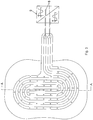
- the Figures 1 and 2 illustrate a treatment arrangement in which a dielectric shielding layer 1, in which an electrode arrangement 2 is embedded such that the shielding layer 1 surrounds the electrode arrangement 2 on all sides.
- the shielding layer 1 is formed with a thickness such that the electrode arrangement 2 is surrounded on all sides with a sufficiently thick dielectric shield that prevents a noticeable current flow.
- the shielding layer 1 forms a lateral connecting tongue 3, into which the electrode arrangement 2 extends.
- the electrode arrangement 2 has two electrode strips 4, which run as strip-shaped conductors parallel to one another and are spirally wound in an oval shape, inner ends 5 being terminated in straight pieces pointing antiparallel in a loop of the other electrode strip.
- the two electrode strips run parallel to one another and end in contact surfaces 6, which are connected to a pole 8 of a high-voltage supply device 9 via connecting lines 7.
- Figure 1 is schematically illustrated that an AC voltage is present at one pole, which oscillates around a ground potential, while the other pole 8 is at the ground potential.
- the electrode arrangement 2 is thus supplied with an alternating high voltage.
- the two electrode strips 4 are arranged in such a way that they always alternate with one another in parallel sections, so that the alternating high voltage of the high-voltage supply device 9 is always present between the sections of the electrode strips lying parallel to one another and generate local electric fields there, which form a dielectric barrier plasma are suitable.
- the dielectric shielding layer 1 is provided in one piece with sections 10, which extend on all sides - with the exception of the connecting tongue 3 - over the electrode arrangement 2 and the shielding layer 1 embedding the electrode arrangement 2 and are designed to be adhesive on their underside 11, so that the treatment arrangement with the other Underside 11 adhesive sections 10 can be attached to the skin of a body part in the manner of a plaster.
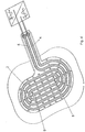
- Figure 2 illustrates the smaller thickness of the sections 10 compared to the remaining shielding layer 1, which embeds the electrode arrangement 2 in the form of the electrode strips 4 on all sides.
- the dielectric shielding layer 1 is provided outside the electrode strips 4 with through openings 12, through which air can reach a wound surface on the one hand and wound secretion from a wound surface on the other, from the underside of the shielding layer 1 forming a treatment side 13 to the distal upper side 14 is transportable.
- the electrode arrangement 2 is a flat arrangement with a small height extension, which is formed in this embodiment of the invention by the flat electrode strips.
- These are preferably formed from an electrically conductive silicone by means of conductive additives, which corresponds to the silicone from which the dielectric shielding layer 1 is made.
- Figure 3 only illustrates that the two poles 8 of the high-voltage supply device can both be connected to alternating alternating voltages, which have a phase shift of 180 ° with respect to one another, so that the resulting voltage difference for forming the local electric fields between the electrode strips 4 has a double amplitude.
- the second exemplary embodiment shown differs from the first exemplary embodiment according to FIGS Figures 1 to 4 only in that the treatment side 13 of the dielectric shielding layer 1 is not smooth, but has a profile 15 in the form of hemispherical elevations, with the tops of which the treatment arrangement can rest on the surface to be treated, in particular on the skin of a part of the body.
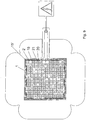
- the exemplary embodiment shown has an essentially square surface of the dielectric shielding layer 1, to which sections 10 'are connected in one piece like a cloverleaf.
- the electrode arrangement 2 ' is formed by a continuously electrically conductive surface in which there are circular through openings 18.
- the electrically conductive surface of the electrode arrangement 2 ' is embedded on all sides in the dielectric shielding layer 1.
- Through-openings 12 of the dielectric shielding layer run concentrically with the through-openings 18, the diameter of which, however, is significantly smaller than the diameter of the through-openings 18 in the electrode arrangement 2 '. This ensures that sufficient insulation to the electrode arrangement 2 ′ is always present in the area of the through openings 12, which ensure ventilation of the wound area and removal of wound secretions.
- the dielectric shielding layer 1 also has a connecting tongue 3 ', into which a corresponding extension of the electrode arrangement 2' extends, the electrode arrangement 2 'also being completely shielded on all sides by the dielectric shielding layer 1 in the region of the connecting tongue 3'.
- Contact is made via a contact point 19, via which a high-voltage potential of the high-voltage supply device 9 is conducted to the electrode arrangement 2 '.
- the body of the surface to be treated forms a counter electrode for the alternating high voltage of the high voltage supply device 9.
- the bottom view according to Figure 9 illustrates a profile 15 'of the treatment side 13 of the dielectric shielding layer 1.
- the profile 15' is formed with lattice-like walls 20, which around the through openings 12, 18 to the surface to be treated open chambers 21 ( Figure 8 ) in which, as in the air gaps 17 of the previous embodiments, a plasma can form when the treatment arrangement rests on the skin or wound surface of a body.
- the electrode arrangements 2, 2 'and the shielding layers 1 consist of chemically essentially the same plastics as so-called liquid silicone rubbers or silicone gels. These plastic materials are insulating as a plastic matrix.
- conductive additives are admixed to the insulating plastic material, so that the required conductive configuration of the electrode arrangements 2, 2' is made possible despite the use of the insulating plastic matrix. In this way, a connection between the electrode arrangement 2, 2 ′ and the dielectric shielding layer 1, which is secure against delamination even when the flexible treatment arrangement is severely deformed, is achieved.
Landscapes
- Health & Medical Sciences (AREA)
- Engineering & Computer Science (AREA)
- General Health & Medical Sciences (AREA)
- Biomedical Technology (AREA)
- Veterinary Medicine (AREA)
- Public Health (AREA)
- Life Sciences & Earth Sciences (AREA)
- Animal Behavior & Ethology (AREA)
- Physics & Mathematics (AREA)
- Plasma & Fusion (AREA)
- Radiology & Medical Imaging (AREA)
- Nuclear Medicine, Radiotherapy & Molecular Imaging (AREA)
- Spectroscopy & Molecular Physics (AREA)
- Heart & Thoracic Surgery (AREA)
- Vascular Medicine (AREA)
- Plasma Technology (AREA)
- Electrotherapy Devices (AREA)
- Shielding Devices Or Components To Electric Or Magnetic Fields (AREA)
- Physical Or Chemical Processes And Apparatus (AREA)
- Liquid Crystal (AREA)
- Materials For Medical Uses (AREA)
- Treatments Of Macromolecular Shaped Articles (AREA)
Priority Applications (1)
| Application Number | Priority Date | Filing Date | Title |
|---|---|---|---|
| PL17713151T PL3452168T3 (pl) | 2016-05-06 | 2017-02-17 | Układ obróbkowy i sposób wytwarzania układu obróbkowego |
Applications Claiming Priority (2)
| Application Number | Priority Date | Filing Date | Title |
|---|---|---|---|
| DE102016108450.6A DE102016108450B4 (de) | 2016-05-06 | 2016-05-06 | Behandlungsanordnung und Verfahren zur Herstellung einer Behandlungsanordnung |
| PCT/DE2017/100138 WO2017190724A1 (de) | 2016-05-06 | 2017-02-17 | Behandlungsanordnung verfahren zur herstellung einer behandlungsanordnung |
Publications (2)
| Publication Number | Publication Date |
|---|---|
| EP3452168A1 EP3452168A1 (de) | 2019-03-13 |
| EP3452168B1 true EP3452168B1 (de) | 2020-08-05 |
Family
ID=58410058
Family Applications (1)
| Application Number | Title | Priority Date | Filing Date |
|---|---|---|---|
| EP17713151.3A Active EP3452168B1 (de) | 2016-05-06 | 2017-02-17 | Behandlungsanordnung und verfahren zur herstellung einer behandlungsanordnung |
Country Status (12)
| Country | Link |
|---|---|
| US (1) | US11660459B2 (pl) |
| EP (1) | EP3452168B1 (pl) |
| JP (1) | JP6900049B2 (pl) |
| KR (1) | KR102769292B1 (pl) |
| CN (1) | CN109069849B (pl) |
| AU (1) | AU2017259758B2 (pl) |
| DE (1) | DE102016108450B4 (pl) |
| DK (1) | DK3452168T3 (pl) |
| ES (1) | ES2820864T3 (pl) |
| MX (1) | MX386763B (pl) |
| PL (1) | PL3452168T3 (pl) |
| WO (1) | WO2017190724A1 (pl) |
Cited By (1)
| Publication number | Priority date | Publication date | Assignee | Title |
|---|---|---|---|---|
| US12463024B2 (en) | 2020-01-15 | 2025-11-04 | Tdk Electronics Ag | Device for generating a dielectric barrier discharge and method for treating an object to be activated |
Families Citing this family (9)
| Publication number | Priority date | Publication date | Assignee | Title |
|---|---|---|---|---|
| DE102017100192A1 (de) * | 2017-01-06 | 2018-07-12 | Cinogy Gmbh | Permanente Wundauflage mit Plasmaelektrode |
| DE102017129718B4 (de) | 2017-12-13 | 2023-05-11 | Cinogy Gmbh | Plasma-Behandlungsgerät |
| JP7483670B2 (ja) | 2018-03-23 | 2024-05-15 | コールドプラズマテック ゲー・エム・ベー・ハー | プラズマアプリケータ |
| US12496456B2 (en) | 2018-03-23 | 2025-12-16 | Coldplasmatech Gmbh | Plasma applicator |
| WO2021260023A1 (de) * | 2020-06-24 | 2021-12-30 | Fraunhofer-Gesellschaft zur Förderung der angewandten Forschung e.V. | Plasmareaktor zur plasmachemischen und/oder plasmakatalytischen umsetzung von verbindungen sowie verwendung eines plasmareaktors |
| DE102022124101A1 (de) | 2022-09-20 | 2024-03-21 | Cinogy Gmbh | Plasma-Behandlungsanordnung |
| DE102023104705A1 (de) | 2023-02-27 | 2024-08-29 | Cinogy Gmbh | Plasma-Behandlungsanordnung |
| DE102023104707B3 (de) | 2023-02-27 | 2024-05-02 | Cinogy Gmbh | Plasmabehandlungsanordnung |
| CN119656409A (zh) * | 2025-01-09 | 2025-03-21 | 北京医科等离子体实验室科技有限公司 | 负压封闭引流敷料及创面治疗装置 |
Family Cites Families (18)
| Publication number | Priority date | Publication date | Assignee | Title |
|---|---|---|---|---|
| US4929811A (en) * | 1988-12-05 | 1990-05-29 | The Lincoln Electric Company | Plasma arc torch interlock with disabling control arrangement system |
| US20060111626A1 (en) * | 2003-03-27 | 2006-05-25 | Cvrx, Inc. | Electrode structures having anti-inflammatory properties and methods of use |
| WO2007037549A1 (ja) | 2005-09-30 | 2007-04-05 | Canon Kabushiki Kaisha | 色素の無色化方法、これを用いた装置及び記録媒体の再生方法 |
| US20070255320A1 (en) * | 2006-04-28 | 2007-11-01 | Cyberonics, Inc. | Method and apparatus for forming insulated implantable electrodes |
| DE102008010188A1 (de) * | 2008-02-20 | 2009-08-27 | Biotronik Crm Patent Ag | Verfahren zur Herstellung eines Isolationsschlauchs und Verfahren zur Herstellung einer Elektrode |
| DE202009011521U1 (de) * | 2009-08-25 | 2010-12-30 | INP Greifswald Leibniz-Institut für Plasmaforschung und Technologie e. V. | Plasma-Manschette |
| GB0919274D0 (en) * | 2009-11-03 | 2009-12-16 | Univ The Glasgow | Plasma generation apparatus and use of plasma generation apparatus |
| DE102009060627B4 (de) | 2009-12-24 | 2014-06-05 | Cinogy Gmbh | Elektrodenanordnung für eine dielektrisch behinderte Plasmabehandlung |
| AT510914B1 (de) * | 2011-01-03 | 2012-10-15 | Lang Leonh | Medizinische elektrode mit gedruckter zuleitung und verfahren zu ihrer herstellung |
| WO2012106735A2 (en) | 2011-02-01 | 2012-08-09 | Moe Medical Devices Llc | Plasma-assisted skin treatment |
| DE102011105713B4 (de) | 2011-06-23 | 2014-06-05 | Cinogy Gmbh | Elektrodenanordnung für eine dielektrisch behinderte Gasentladung |
| EP3199201A1 (en) * | 2011-09-17 | 2017-08-02 | Moe Medical Devices LLC | Systems for electric field and/or plasma-assisted onychomycosis treatment |
| JP6317927B2 (ja) * | 2012-01-09 | 2018-04-25 | ムー・メディカル・デバイスズ・エルエルシーMoe Medical Devices Llc | プラズマ補助皮膚処置 |
| ITBO20130087A1 (it) | 2013-02-28 | 2014-08-29 | Univ Bologna Alma Mater | Dispositivo e metodo di generazione di plasma freddo |
| DE102013019057B4 (de) | 2013-11-15 | 2018-02-15 | Cinogy Gmbh | Gerät zur Behandlung einer Körperoberfläche eines lebenden Körpers |
| DE102014013716B4 (de) | 2014-09-11 | 2022-04-07 | Cinogy Gmbh | Elektrodenanordnung zur Ausbildung einer dielektrisch behinderten Plasmaentladung |
| CN105079955B (zh) * | 2015-09-11 | 2017-06-20 | 郑州大学 | 自动热熔式双绞线刺激电极制备装置 |
| DE102015117715A1 (de) * | 2015-10-19 | 2017-04-20 | Cinogy Gmbh | Elektrodenanordnung für eine dielektrisch behinderte Plasmabehandlung |
-
2016
- 2016-05-06 DE DE102016108450.6A patent/DE102016108450B4/de not_active Expired - Fee Related
-
2017
- 2017-02-17 WO PCT/DE2017/100138 patent/WO2017190724A1/de not_active Ceased
- 2017-02-17 KR KR1020187034588A patent/KR102769292B1/ko active Active
- 2017-02-17 JP JP2018546831A patent/JP6900049B2/ja active Active
- 2017-02-17 EP EP17713151.3A patent/EP3452168B1/de active Active
- 2017-02-17 US US16/095,118 patent/US11660459B2/en active Active
- 2017-02-17 MX MX2018011051A patent/MX386763B/es unknown
- 2017-02-17 DK DK17713151.3T patent/DK3452168T3/da active
- 2017-02-17 CN CN201780027405.6A patent/CN109069849B/zh not_active Expired - Fee Related
- 2017-02-17 ES ES17713151T patent/ES2820864T3/es active Active
- 2017-02-17 AU AU2017259758A patent/AU2017259758B2/en active Active
- 2017-02-17 PL PL17713151T patent/PL3452168T3/pl unknown
Non-Patent Citations (1)
| Title |
|---|
| None * |
Cited By (1)
| Publication number | Priority date | Publication date | Assignee | Title |
|---|---|---|---|---|
| US12463024B2 (en) | 2020-01-15 | 2025-11-04 | Tdk Electronics Ag | Device for generating a dielectric barrier discharge and method for treating an object to be activated |
Also Published As
| Publication number | Publication date |
|---|---|
| CN109069849A (zh) | 2018-12-21 |
| DE102016108450B4 (de) | 2020-01-02 |
| KR102769292B1 (ko) | 2025-02-18 |
| US11660459B2 (en) | 2023-05-30 |
| WO2017190724A8 (de) | 2018-03-08 |
| PL3452168T3 (pl) | 2021-01-25 |
| DE102016108450A1 (de) | 2017-11-09 |
| KR20190005900A (ko) | 2019-01-16 |
| MX386763B (es) | 2025-03-19 |
| EP3452168A1 (de) | 2019-03-13 |
| AU2017259758B2 (en) | 2019-08-15 |
| DK3452168T3 (da) | 2020-11-09 |
| JP2019521467A (ja) | 2019-07-25 |
| US20190308027A1 (en) | 2019-10-10 |
| MX2018011051A (es) | 2019-01-24 |
| CN109069849B (zh) | 2022-06-07 |
| JP6900049B2 (ja) | 2021-07-07 |
| BR112018069710A2 (pt) | 2019-02-05 |
| ES2820864T3 (es) | 2021-04-22 |
| AU2017259758A1 (en) | 2018-11-15 |
| WO2017190724A1 (de) | 2017-11-09 |
Similar Documents
| Publication | Publication Date | Title |
|---|---|---|
| EP3452168B1 (de) | Behandlungsanordnung und verfahren zur herstellung einer behandlungsanordnung | |
| EP3192333B1 (de) | Elektrodenanordnung zur ausbildung einer dielektrisch behinderten plasmaentladung | |
| EP3448130B1 (de) | Elektrodenanordnung zur ausbildung einer dielektrisch behinderten plasmaentladung | |
| EP3566552B1 (de) | Flächiges flexibles auflagestück für eine dielektrisch behinderte plasmabehandlung | |
| EP2723447B1 (de) | Elektrodenanordnung für eine dielektrisch behinderte gasentladung | |
| EP3051926B1 (de) | Plasmaerzeugungseinrichtung, plasmaerzeugungssystem, verfahren zur erzeugung von plasma und verfahren zur desinfektion von oberflächen | |
| DE102007030915A1 (de) | Vorrichtung zur Behandlung von Oberflächen mit einem mittels einer Elektrode über ein Feststoff-Dielektrikum durch eine dielektrische behinderte Gasentladung erzeugten Plasma | |
| DE102010053213B4 (de) | Wundverband zur Elektrostimulation sowie Verfahren zur Herstellung eines solchen Wundverbands | |
| EP3171676A1 (de) | Plasmaerzeugungsvorrichtung, plasmaerzeugungssystem und verfahren zur erzeugung von plasma | |
| WO2010006920A1 (de) | Anordnung zur herstellung von plasma | |
| EP3329747B1 (de) | Elektrodenanordnung und plasmabehandlungsvorrichtung für eine oberflächenbehandlung eines körpers | |
| DE102017129718B4 (de) | Plasma-Behandlungsgerät | |
| DE102014213967A1 (de) | Vorrichtung zur Hydophilierung von Zahnimplantaten | |
| DE202010010700U1 (de) | Therapievorrichtung | |
| DE102010039750A1 (de) | Kabelgarnitur mut einem Feldsteuerelement und Verfahren zum Herstellen einer Kabelgarnitur | |
| BR112018069710B1 (pt) | Arranjo de tratamento, dispositivo de tratamento com um arranjo de tratamento e processo para a produção de um arranjo de tratamento |
Legal Events
| Date | Code | Title | Description |
|---|---|---|---|
| STAA | Information on the status of an ep patent application or granted ep patent |
Free format text: STATUS: UNKNOWN |
|
| STAA | Information on the status of an ep patent application or granted ep patent |
Free format text: STATUS: THE INTERNATIONAL PUBLICATION HAS BEEN MADE |
|
| PUAI | Public reference made under article 153(3) epc to a published international application that has entered the european phase |
Free format text: ORIGINAL CODE: 0009012 |
|
| STAA | Information on the status of an ep patent application or granted ep patent |
Free format text: STATUS: REQUEST FOR EXAMINATION WAS MADE |
|
| 17P | Request for examination filed |
Effective date: 20181018 |
|
| AK | Designated contracting states |
Kind code of ref document: A1 Designated state(s): AL AT BE BG CH CY CZ DE DK EE ES FI FR GB GR HR HU IE IS IT LI LT LU LV MC MK MT NL NO PL PT RO RS SE SI SK SM TR |
|
| AX | Request for extension of the european patent |
Extension state: BA ME |
|
| DAV | Request for validation of the european patent (deleted) | ||
| DAX | Request for extension of the european patent (deleted) | ||
| STAA | Information on the status of an ep patent application or granted ep patent |
Free format text: STATUS: EXAMINATION IS IN PROGRESS |
|
| 17Q | First examination report despatched |
Effective date: 20191014 |
|
| GRAP | Despatch of communication of intention to grant a patent |
Free format text: ORIGINAL CODE: EPIDOSNIGR1 |
|
| STAA | Information on the status of an ep patent application or granted ep patent |
Free format text: STATUS: GRANT OF PATENT IS INTENDED |
|
| INTG | Intention to grant announced |
Effective date: 20200303 |
|
| GRAS | Grant fee paid |
Free format text: ORIGINAL CODE: EPIDOSNIGR3 |
|
| GRAA | (expected) grant |
Free format text: ORIGINAL CODE: 0009210 |
|
| STAA | Information on the status of an ep patent application or granted ep patent |
Free format text: STATUS: THE PATENT HAS BEEN GRANTED |
|
| AK | Designated contracting states |
Kind code of ref document: B1 Designated state(s): AL AT BE BG CH CY CZ DE DK EE ES FI FR GB GR HR HU IE IS IT LI LT LU LV MC MK MT NL NO PL PT RO RS SE SI SK SM TR |
|
| REG | Reference to a national code |
Ref country code: GB Ref legal event code: FG4D Free format text: NOT ENGLISH |
|
| REG | Reference to a national code |
Ref country code: CH Ref legal event code: EP |
|
| REG | Reference to a national code |
Ref country code: AT Ref legal event code: REF Ref document number: 1297861 Country of ref document: AT Kind code of ref document: T Effective date: 20200815 |
|
| REG | Reference to a national code |
Ref country code: DE Ref legal event code: R096 Ref document number: 502017006567 Country of ref document: DE |
|
| REG | Reference to a national code |
Ref country code: IE Ref legal event code: FG4D Free format text: LANGUAGE OF EP DOCUMENT: GERMAN |
|
| REG | Reference to a national code |
Ref country code: CH Ref legal event code: NV Representative=s name: BRAUNPAT BRAUN EDER AG, CH |
|
| REG | Reference to a national code |
Ref country code: DK Ref legal event code: T3 Effective date: 20201103 |
|
| REG | Reference to a national code |
Ref country code: NL Ref legal event code: FP |
|
| REG | Reference to a national code |
Ref country code: SE Ref legal event code: TRGR |
|
| REG | Reference to a national code |
Ref country code: LT Ref legal event code: MG4D |
|
| PG25 | Lapsed in a contracting state [announced via postgrant information from national office to epo] |
Ref country code: PT Free format text: LAPSE BECAUSE OF FAILURE TO SUBMIT A TRANSLATION OF THE DESCRIPTION OR TO PAY THE FEE WITHIN THE PRESCRIBED TIME-LIMIT Effective date: 20201207 Ref country code: HR Free format text: LAPSE BECAUSE OF FAILURE TO SUBMIT A TRANSLATION OF THE DESCRIPTION OR TO PAY THE FEE WITHIN THE PRESCRIBED TIME-LIMIT Effective date: 20200805 Ref country code: LT Free format text: LAPSE BECAUSE OF FAILURE TO SUBMIT A TRANSLATION OF THE DESCRIPTION OR TO PAY THE FEE WITHIN THE PRESCRIBED TIME-LIMIT Effective date: 20200805 Ref country code: FI Free format text: LAPSE BECAUSE OF FAILURE TO SUBMIT A TRANSLATION OF THE DESCRIPTION OR TO PAY THE FEE WITHIN THE PRESCRIBED TIME-LIMIT Effective date: 20200805 Ref country code: NO Free format text: LAPSE BECAUSE OF FAILURE TO SUBMIT A TRANSLATION OF THE DESCRIPTION OR TO PAY THE FEE WITHIN THE PRESCRIBED TIME-LIMIT Effective date: 20201105 Ref country code: BG Free format text: LAPSE BECAUSE OF FAILURE TO SUBMIT A TRANSLATION OF THE DESCRIPTION OR TO PAY THE FEE WITHIN THE PRESCRIBED TIME-LIMIT Effective date: 20201105 Ref country code: GR Free format text: LAPSE BECAUSE OF FAILURE TO SUBMIT A TRANSLATION OF THE DESCRIPTION OR TO PAY THE FEE WITHIN THE PRESCRIBED TIME-LIMIT Effective date: 20201106 |
|
| PG25 | Lapsed in a contracting state [announced via postgrant information from national office to epo] |
Ref country code: IS Free format text: LAPSE BECAUSE OF FAILURE TO SUBMIT A TRANSLATION OF THE DESCRIPTION OR TO PAY THE FEE WITHIN THE PRESCRIBED TIME-LIMIT Effective date: 20201205 Ref country code: RS Free format text: LAPSE BECAUSE OF FAILURE TO SUBMIT A TRANSLATION OF THE DESCRIPTION OR TO PAY THE FEE WITHIN THE PRESCRIBED TIME-LIMIT Effective date: 20200805 Ref country code: LV Free format text: LAPSE BECAUSE OF FAILURE TO SUBMIT A TRANSLATION OF THE DESCRIPTION OR TO PAY THE FEE WITHIN THE PRESCRIBED TIME-LIMIT Effective date: 20200805 |
|
| REG | Reference to a national code |
Ref country code: ES Ref legal event code: FG2A Ref document number: 2820864 Country of ref document: ES Kind code of ref document: T3 Effective date: 20210422 |
|
| PG25 | Lapsed in a contracting state [announced via postgrant information from national office to epo] |
Ref country code: SM Free format text: LAPSE BECAUSE OF FAILURE TO SUBMIT A TRANSLATION OF THE DESCRIPTION OR TO PAY THE FEE WITHIN THE PRESCRIBED TIME-LIMIT Effective date: 20200805 Ref country code: CZ Free format text: LAPSE BECAUSE OF FAILURE TO SUBMIT A TRANSLATION OF THE DESCRIPTION OR TO PAY THE FEE WITHIN THE PRESCRIBED TIME-LIMIT Effective date: 20200805 Ref country code: RO Free format text: LAPSE BECAUSE OF FAILURE TO SUBMIT A TRANSLATION OF THE DESCRIPTION OR TO PAY THE FEE WITHIN THE PRESCRIBED TIME-LIMIT Effective date: 20200805 Ref country code: EE Free format text: LAPSE BECAUSE OF FAILURE TO SUBMIT A TRANSLATION OF THE DESCRIPTION OR TO PAY THE FEE WITHIN THE PRESCRIBED TIME-LIMIT Effective date: 20200805 |
|
| REG | Reference to a national code |
Ref country code: DE Ref legal event code: R097 Ref document number: 502017006567 Country of ref document: DE |
|
| PG25 | Lapsed in a contracting state [announced via postgrant information from national office to epo] |
Ref country code: AL Free format text: LAPSE BECAUSE OF FAILURE TO SUBMIT A TRANSLATION OF THE DESCRIPTION OR TO PAY THE FEE WITHIN THE PRESCRIBED TIME-LIMIT Effective date: 20200805 |
|
| PLBE | No opposition filed within time limit |
Free format text: ORIGINAL CODE: 0009261 |
|
| STAA | Information on the status of an ep patent application or granted ep patent |
Free format text: STATUS: NO OPPOSITION FILED WITHIN TIME LIMIT |
|
| PG25 | Lapsed in a contracting state [announced via postgrant information from national office to epo] |
Ref country code: SK Free format text: LAPSE BECAUSE OF FAILURE TO SUBMIT A TRANSLATION OF THE DESCRIPTION OR TO PAY THE FEE WITHIN THE PRESCRIBED TIME-LIMIT Effective date: 20200805 |
|
| 26N | No opposition filed |
Effective date: 20210507 |
|
| PG25 | Lapsed in a contracting state [announced via postgrant information from national office to epo] |
Ref country code: SI Free format text: LAPSE BECAUSE OF FAILURE TO SUBMIT A TRANSLATION OF THE DESCRIPTION OR TO PAY THE FEE WITHIN THE PRESCRIBED TIME-LIMIT Effective date: 20200805 |
|
| PG25 | Lapsed in a contracting state [announced via postgrant information from national office to epo] |
Ref country code: MC Free format text: LAPSE BECAUSE OF FAILURE TO SUBMIT A TRANSLATION OF THE DESCRIPTION OR TO PAY THE FEE WITHIN THE PRESCRIBED TIME-LIMIT Effective date: 20200805 |
|
| REG | Reference to a national code |
Ref country code: BE Ref legal event code: MM Effective date: 20210228 |
|
| PG25 | Lapsed in a contracting state [announced via postgrant information from national office to epo] |
Ref country code: LU Free format text: LAPSE BECAUSE OF NON-PAYMENT OF DUE FEES Effective date: 20210217 |
|
| PG25 | Lapsed in a contracting state [announced via postgrant information from national office to epo] |
Ref country code: IE Free format text: LAPSE BECAUSE OF NON-PAYMENT OF DUE FEES Effective date: 20210217 |
|
| PG25 | Lapsed in a contracting state [announced via postgrant information from national office to epo] |
Ref country code: BE Free format text: LAPSE BECAUSE OF NON-PAYMENT OF DUE FEES Effective date: 20210228 |
|
| REG | Reference to a national code |
Ref country code: AT Ref legal event code: MM01 Ref document number: 1297861 Country of ref document: AT Kind code of ref document: T Effective date: 20220217 |
|
| PG25 | Lapsed in a contracting state [announced via postgrant information from national office to epo] |
Ref country code: AT Free format text: LAPSE BECAUSE OF NON-PAYMENT OF DUE FEES Effective date: 20220217 |
|
| P01 | Opt-out of the competence of the unified patent court (upc) registered |
Effective date: 20230523 |
|
| PG25 | Lapsed in a contracting state [announced via postgrant information from national office to epo] |
Ref country code: CY Free format text: LAPSE BECAUSE OF FAILURE TO SUBMIT A TRANSLATION OF THE DESCRIPTION OR TO PAY THE FEE WITHIN THE PRESCRIBED TIME-LIMIT Effective date: 20200805 |
|
| PG25 | Lapsed in a contracting state [announced via postgrant information from national office to epo] |
Ref country code: HU Free format text: LAPSE BECAUSE OF FAILURE TO SUBMIT A TRANSLATION OF THE DESCRIPTION OR TO PAY THE FEE WITHIN THE PRESCRIBED TIME-LIMIT; INVALID AB INITIO Effective date: 20170217 |
|
| PG25 | Lapsed in a contracting state [announced via postgrant information from national office to epo] |
Ref country code: MK Free format text: LAPSE BECAUSE OF FAILURE TO SUBMIT A TRANSLATION OF THE DESCRIPTION OR TO PAY THE FEE WITHIN THE PRESCRIBED TIME-LIMIT Effective date: 20200805 |
|
| PGFP | Annual fee paid to national office [announced via postgrant information from national office to epo] |
Ref country code: TR Payment date: 20240208 Year of fee payment: 8 |
|
| PG25 | Lapsed in a contracting state [announced via postgrant information from national office to epo] |
Ref country code: MT Free format text: LAPSE BECAUSE OF FAILURE TO SUBMIT A TRANSLATION OF THE DESCRIPTION OR TO PAY THE FEE WITHIN THE PRESCRIBED TIME-LIMIT Effective date: 20200805 |
|
| PGFP | Annual fee paid to national office [announced via postgrant information from national office to epo] |
Ref country code: NL Payment date: 20250220 Year of fee payment: 9 |
|
| PGFP | Annual fee paid to national office [announced via postgrant information from national office to epo] |
Ref country code: DE Payment date: 20250224 Year of fee payment: 9 |
|
| PGFP | Annual fee paid to national office [announced via postgrant information from national office to epo] |
Ref country code: DK Payment date: 20250219 Year of fee payment: 9 |
|
| PGFP | Annual fee paid to national office [announced via postgrant information from national office to epo] |
Ref country code: ES Payment date: 20250318 Year of fee payment: 9 |
|
| PGFP | Annual fee paid to national office [announced via postgrant information from national office to epo] |
Ref country code: SE Payment date: 20250219 Year of fee payment: 9 |
|
| PGFP | Annual fee paid to national office [announced via postgrant information from national office to epo] |
Ref country code: CH Payment date: 20250301 Year of fee payment: 9 |
|
| PGFP | Annual fee paid to national office [announced via postgrant information from national office to epo] |
Ref country code: PL Payment date: 20250207 Year of fee payment: 9 Ref country code: FR Payment date: 20250219 Year of fee payment: 9 |
|
| PGFP | Annual fee paid to national office [announced via postgrant information from national office to epo] |
Ref country code: IT Payment date: 20250228 Year of fee payment: 9 Ref country code: GB Payment date: 20250220 Year of fee payment: 9 |