EP3451513B1 - Rundläufermaschine zur behandlung von behältern - Google Patents
Rundläufermaschine zur behandlung von behältern Download PDFInfo
- Publication number
- EP3451513B1 EP3451513B1 EP18170332.3A EP18170332A EP3451513B1 EP 3451513 B1 EP3451513 B1 EP 3451513B1 EP 18170332 A EP18170332 A EP 18170332A EP 3451513 B1 EP3451513 B1 EP 3451513B1
- Authority
- EP
- European Patent Office
- Prior art keywords
- container table
- motor
- bearing
- rotary machine
- machine according
- Prior art date
- Legal status (The legal status is an assumption and is not a legal conclusion. Google has not performed a legal analysis and makes no representation as to the accuracy of the status listed.)
- Active
Links
Images
Classifications
-
- G—PHYSICS
- G01—MEASURING; TESTING
- G01D—MEASURING NOT SPECIALLY ADAPTED FOR A SPECIFIC VARIABLE; ARRANGEMENTS FOR MEASURING TWO OR MORE VARIABLES NOT COVERED IN A SINGLE OTHER SUBCLASS; TARIFF METERING APPARATUS; MEASURING OR TESTING NOT OTHERWISE PROVIDED FOR
- G01D5/00—Mechanical means for transferring the output of a sensing member; Means for converting the output of a sensing member to another variable where the form or nature of the sensing member does not constrain the means for converting; Transducers not specially adapted for a specific variable
-
- B—PERFORMING OPERATIONS; TRANSPORTING
- B65—CONVEYING; PACKING; STORING; HANDLING THIN OR FILAMENTARY MATERIAL
- B65C—LABELLING OR TAGGING MACHINES, APPARATUS, OR PROCESSES
- B65C9/00—Details of labelling machines or apparatus
- B65C9/02—Devices for moving articles, e.g. containers, past labelling station
-
- B—PERFORMING OPERATIONS; TRANSPORTING
- B65—CONVEYING; PACKING; STORING; HANDLING THIN OR FILAMENTARY MATERIAL
- B65C—LABELLING OR TAGGING MACHINES, APPARATUS, OR PROCESSES
- B65C9/00—Details of labelling machines or apparatus
- B65C9/02—Devices for moving articles, e.g. containers, past labelling station
- B65C9/04—Devices for moving articles, e.g. containers, past labelling station having means for rotating the articles
-
- B—PERFORMING OPERATIONS; TRANSPORTING
- B08—CLEANING
- B08B—CLEANING IN GENERAL; PREVENTION OF FOULING IN GENERAL
- B08B9/00—Cleaning hollow articles by methods or apparatus specially adapted thereto
- B08B9/08—Cleaning containers, e.g. tanks
- B08B9/20—Cleaning containers, e.g. tanks by using apparatus into or on to which containers, e.g. bottles, jars, cans are brought
- B08B9/28—Cleaning containers, e.g. tanks by using apparatus into or on to which containers, e.g. bottles, jars, cans are brought the apparatus cleaning by splash, spray, or jet application, with or without soaking
- B08B9/30—Cleaning containers, e.g. tanks by using apparatus into or on to which containers, e.g. bottles, jars, cans are brought the apparatus cleaning by splash, spray, or jet application, with or without soaking and having conveyors
- B08B9/32—Rotating conveyors
-
- B—PERFORMING OPERATIONS; TRANSPORTING
- B29—WORKING OF PLASTICS; WORKING OF SUBSTANCES IN A PLASTIC STATE IN GENERAL
- B29C—SHAPING OR JOINING OF PLASTICS; SHAPING OF MATERIAL IN A PLASTIC STATE, NOT OTHERWISE PROVIDED FOR; AFTER-TREATMENT OF THE SHAPED PRODUCTS, e.g. REPAIRING
- B29C49/00—Blow-moulding, i.e. blowing a preform or parison to a desired shape within a mould; Apparatus therefor
- B29C49/28—Blow-moulding apparatus
- B29C49/30—Blow-moulding apparatus having movable moulds or mould parts
- B29C49/36—Blow-moulding apparatus having movable moulds or mould parts rotatable about one axis
-
- B—PERFORMING OPERATIONS; TRANSPORTING
- B41—PRINTING; LINING MACHINES; TYPEWRITERS; STAMPS
- B41J—TYPEWRITERS; SELECTIVE PRINTING MECHANISMS, i.e. MECHANISMS PRINTING OTHERWISE THAN FROM A FORME; CORRECTION OF TYPOGRAPHICAL ERRORS
- B41J3/00—Typewriters or selective printing or marking mechanisms characterised by the purpose for which they are constructed
- B41J3/407—Typewriters or selective printing or marking mechanisms characterised by the purpose for which they are constructed for marking on special material
-
- B—PERFORMING OPERATIONS; TRANSPORTING
- B65—CONVEYING; PACKING; STORING; HANDLING THIN OR FILAMENTARY MATERIAL
- B65C—LABELLING OR TAGGING MACHINES, APPARATUS, OR PROCESSES
- B65C9/00—Details of labelling machines or apparatus
- B65C9/06—Devices for presenting articles in predetermined attitude or position at labelling station
-
- B—PERFORMING OPERATIONS; TRANSPORTING
- B65—CONVEYING; PACKING; STORING; HANDLING THIN OR FILAMENTARY MATERIAL
- B65C—LABELLING OR TAGGING MACHINES, APPARATUS, OR PROCESSES
- B65C9/00—Details of labelling machines or apparatus
- B65C9/40—Controls; Safety devices
-
- B—PERFORMING OPERATIONS; TRANSPORTING
- B67—OPENING, CLOSING OR CLEANING BOTTLES, JARS OR SIMILAR CONTAINERS; LIQUID HANDLING
- B67B—APPLYING CLOSURE MEMBERS TO BOTTLES JARS, OR SIMILAR CONTAINERS; OPENING CLOSED CONTAINERS
- B67B1/00—Closing bottles, jars or similar containers by applying stoppers
- B67B1/08—Securing stoppers, e.g. swing stoppers, which are held in position by associated pressure-applying means coacting with the bottle neck
-
- B—PERFORMING OPERATIONS; TRANSPORTING
- B67—OPENING, CLOSING OR CLEANING BOTTLES, JARS OR SIMILAR CONTAINERS; LIQUID HANDLING
- B67B—APPLYING CLOSURE MEMBERS TO BOTTLES JARS, OR SIMILAR CONTAINERS; OPENING CLOSED CONTAINERS
- B67B3/00—Closing bottles, jars or similar containers by applying caps
-
- B—PERFORMING OPERATIONS; TRANSPORTING
- B67—OPENING, CLOSING OR CLEANING BOTTLES, JARS OR SIMILAR CONTAINERS; LIQUID HANDLING
- B67C—CLEANING, FILLING WITH LIQUIDS OR SEMILIQUIDS, OR EMPTYING, OF BOTTLES, JARS, CANS, CASKS, BARRELS, OR SIMILAR CONTAINERS, NOT OTHERWISE PROVIDED FOR; FUNNELS
- B67C3/00—Bottling liquids or semiliquids; Filling jars or cans with liquids or semiliquids using bottling or like apparatus; Filling casks or barrels with liquids or semiliquids
- B67C3/02—Bottling liquids or semiliquids; Filling jars or cans with liquids or semiliquids using bottling or like apparatus
- B67C3/22—Details
- B67C3/24—Devices for supporting or handling bottles
-
- G—PHYSICS
- G01—MEASURING; TESTING
- G01D—MEASURING NOT SPECIALLY ADAPTED FOR A SPECIFIC VARIABLE; ARRANGEMENTS FOR MEASURING TWO OR MORE VARIABLES NOT COVERED IN A SINGLE OTHER SUBCLASS; TARIFF METERING APPARATUS; MEASURING OR TESTING NOT OTHERWISE PROVIDED FOR
- G01D5/00—Mechanical means for transferring the output of a sensing member; Means for converting the output of a sensing member to another variable where the form or nature of the sensing member does not constrain the means for converting; Transducers not specially adapted for a specific variable
- G01D5/02—Mechanical means for transferring the output of a sensing member; Means for converting the output of a sensing member to another variable where the form or nature of the sensing member does not constrain the means for converting; Transducers not specially adapted for a specific variable using mechanical means
- G01D5/04—Mechanical means for transferring the output of a sensing member; Means for converting the output of a sensing member to another variable where the form or nature of the sensing member does not constrain the means for converting; Transducers not specially adapted for a specific variable using mechanical means using levers; using cams; using gearing
-
- G—PHYSICS
- G01—MEASURING; TESTING
- G01D—MEASURING NOT SPECIALLY ADAPTED FOR A SPECIFIC VARIABLE; ARRANGEMENTS FOR MEASURING TWO OR MORE VARIABLES NOT COVERED IN A SINGLE OTHER SUBCLASS; TARIFF METERING APPARATUS; MEASURING OR TESTING NOT OTHERWISE PROVIDED FOR
- G01D5/00—Mechanical means for transferring the output of a sensing member; Means for converting the output of a sensing member to another variable where the form or nature of the sensing member does not constrain the means for converting; Transducers not specially adapted for a specific variable
- G01D5/12—Mechanical means for transferring the output of a sensing member; Means for converting the output of a sensing member to another variable where the form or nature of the sensing member does not constrain the means for converting; Transducers not specially adapted for a specific variable using electric or magnetic means
- G01D5/244—Mechanical means for transferring the output of a sensing member; Means for converting the output of a sensing member to another variable where the form or nature of the sensing member does not constrain the means for converting; Transducers not specially adapted for a specific variable using electric or magnetic means influencing characteristics of pulses or pulse trains; generating pulses or pulse trains
- G01D5/249—Mechanical means for transferring the output of a sensing member; Means for converting the output of a sensing member to another variable where the form or nature of the sensing member does not constrain the means for converting; Transducers not specially adapted for a specific variable using electric or magnetic means influencing characteristics of pulses or pulse trains; generating pulses or pulse trains using pulse code
- G01D5/2497—Absolute encoders
-
- G—PHYSICS
- G01—MEASURING; TESTING
- G01N—INVESTIGATING OR ANALYSING MATERIALS BY DETERMINING THEIR CHEMICAL OR PHYSICAL PROPERTIES
- G01N21/00—Investigating or analysing materials by the use of optical means, i.e. using sub-millimetre waves, infrared, visible or ultraviolet light
- G01N21/84—Systems specially adapted for particular applications
- G01N21/88—Investigating the presence of flaws or contamination
- G01N21/90—Investigating the presence of flaws or contamination in a container or its contents
-
- H—ELECTRICITY
- H02—GENERATION; CONVERSION OR DISTRIBUTION OF ELECTRIC POWER
- H02K—DYNAMO-ELECTRIC MACHINES
- H02K26/00—Machines adapted to function as torque motors, i.e. to exert a torque when stalled
-
- H—ELECTRICITY
- H02—GENERATION; CONVERSION OR DISTRIBUTION OF ELECTRIC POWER
- H02K—DYNAMO-ELECTRIC MACHINES
- H02K7/00—Arrangements for handling mechanical energy structurally associated with dynamo-electric machines, e.g. structural association with mechanical driving motors or auxiliary dynamo-electric machines
- H02K7/14—Structural association with mechanical loads, e.g. with hand-held machine tools or fans
Definitions
- the invention relates to a rotary machine according to the preamble of claims 1 and 2, respectively.
- Generic rotary machines for the treatment of containers are from the DE 10 2013 218438 A1 known.
- a rotary encoder arranged centrally on the central axis of the rotary machine is used to directly determine the rotational position of the container table, that is to say without indirect speed measurement on the drive motor and / or an interposed gear.
- the drive motor extends beyond the rotary encoder in the radial direction.
- a rotary machine which, with the exception of a radially inner bearing of the container table or its support structure, is of the generic type.
- the rotary encoder is expediently installed either directly on a lower end of the central shaft that is accessible in the motor or directly on the upper shaft end. It can be a rotary pulse encoder, an absolute encoder and / or a central rotary encoder.
- the encoder system can, however, also be arranged laterally on or next to the motor and coupled to the shaft end via a toothed belt.
- the rotary machine comprises a stationary underframe, a rotatable container table for receiving the containers, a motor designed as an internal rotor for direct drive of the container table, a bearing for supporting the container table and / or a support structure on the underframe radially outside of the motor, which is connected to the container table in a rotationally fixed manner, and a rotary encoder for determining the rotational position of the container table.
- both the accuracy of the rotary encoder, in particular its angular resolution, and the accessibility of the rotary encoder for maintenance measures can be improved compared to a rotary encoder arranged centrally in the area of the motor.
- the rotary encoder consists of at least one sensor and at least one measuring standard scanned by the sensor.
- An arrangement radially outside the motor is understood to mean that both the sensor and the material measure are arranged radially outside the stator and the rotor of the motor.
- the rotary encoder accordingly comprises either: a stationary sensor connected to the subframe and a measuring standard for the sensor, which is formed / fastened on the container table or on the support structure; or a sensor formed / fastened on the container table or on the support structure and a fixed measuring scale for the sensor that is connected to the underframe.
- the container table and / or its support structure are connected to the internal rotor of the motor.
- the bearing is designed to absorb the axial forces and radial forces that occur during operation.
- the rotary encoder is preferably arranged in the area of the container table and / or the support structure at a radial distance of less than 0.2 m from the bearing. This enables a low-vibration and thus more precise measurement of the rotational position as a result of increased mechanical stability in the vicinity of the bearing.
- the radial position of the bearing is predetermined, for example, by the center point of the bearing cross-section.
- the rotary encoder includes a fixed sensor, the electrical power supply and the reading out of measurement data are simplified.
- the rotary encoder comprises a material measure for the sensor which is formed and / or fastened on the container table and / or support structure
- the material measure can be arranged at a suitable radial distance from the center axis of the container table.
- the material measure is preferably arranged below and / or radially outside the bearing. This increases the precision of the determination of the rotational position and facilitates access to the rotary encoder for maintenance work.
- the motor is preferably a torque motor.
- the bearing is preferably an axial-radial bearing and in particular a crossed roller bearing. This enables, for example, a pretensioning of the bearing in order to minimize deviations in axial run-out of the container table and / or deviations in parallelism between the container table and the base.
- the bearing preferably has a run-out deviation of at most 0.015 mm towards the container table and / or a parallelism deviation of at most 0.15 mm towards the container table and the stand. Precise container handling can thus be achieved even with pitch circle diameters of at least 1.5 m.
- the container table preferably has a pitch circle diameter of 1.5 to 2.5 m, so that containers can be treated with a comparatively high machine output. A rotational position measurement radially outside the motor is then particularly advantageous for precise treatment.
- the bearing is preferably arranged radially between the motor and the pitch circle of the container table.
- the bearing then lies in particular radially within drive motors for turntable to hold the containers. This favors a mechanically stable yet compact design of the rotary machine.
- the rotary machine is preferably designed as a direct printing machine, labeling machine, capper, filler, stretch blow molding machine, rinser, inspection machine or other container treatment machine.
- the precise determination of the rotational position of the associated container table is used for precise interaction with the treatment units present on the rotary machine. These can, for example, be docked in a stationary manner and / or revolve around the container table.
- access to the rotary encoder is made easier, for example for checking and / or replacing the sensors and / or the measuring standard, depending on the maintenance intervals.
- the stator of the motor is suspended and attached to the base in a detachable manner at the bottom. This makes maintenance work on the engine easier.
- the rotor of the motor is preferably designed as a hollow shaft and / or surrounds a hollow shaft.
- the hollow shaft can then be used for media connections between the fixed part and the rotating part of the rotary machine.
- Lines for media supply, in particular for energy supply, compressed gas supply or the like, of the container table and / or a machine upper part connected to the container table in a rotationally fixed manner are then preferably arranged within the hollow shaft.
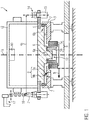
- the rotary machine 1 for the treatment of containers 2 comprises a stationary underframe 3, a rotatable container table 4 for receiving the container 2 on a pitch circle 4a and a motor 5 designed as an internal rotor for direct drive of the container table 4. This can thereby around a central axis 1a of the rotary machine 1 can in particular be rotated continuously.
- the motor 5 is in particular a torque motor with an external stator 5a and an internal rotor 5b.
- the motor 5 is connected to the container table 4 by means of a support structure 6.
- the support structure 6 comprises, for example, a central connecting section 6a for the rotationally fixed coupling to the rotor 5b.
- the support structure 6 preferably comprises an outer support section 6b for the non-rotatable coupling and support of the container table 4.
- the support structure 6 is supported on the stationary subframe 3 by means of an annular bearing 7.
- the bearing 7 is in particular an axial-radial bearing for absorbing axial forces and radial forces during the treatment of the container 2.
- the bearing 7 supports the container table 4 and / or the support structure 6 in a region 8 lying radially outside the motor 5, which is defined, for example, with respect to the outer circumference of the stator 5a.
- the rotary encoder 9 preferably comprises a stationary sensor 9a connected to the subframe 3 and a measuring standard 9b for the sensor 9a which is formed / fastened on the container table 4 or on the support structure 6.
- the material measure 9a is a fully developed length / angle scale with an origin recognizable by the sensor 9a and is scanned by the sensor 9a, preferably without contact.
- the sensor 9a is connected to a schematically indicated controller 10 for the transmission of rotational position data of the container table 4. This can be done wirelessly or wired.
- the rotor 5b of the motor 5 preferably comprises and / or encloses a central channel 13 which is in the Fig. 1 is only indicated schematically.
- the central channel 13 is suitable for the media supply of the container table 4 and / or the upper part of the machine 12.
- media lines, data lines or the like can be routed from the stationary to the rotating part of the rotary machine 1.
- FIG. 1 are also shown schematically turntable 14 for receiving the container 2, individual drive motors 15 for the turntable 14 and centering bells 16 for clamping the container 2 on the turntable 14 and a lifting curve 17 for lowering the centering bells 16 on the container 2.
- the Fig. 2 illustrates a specific embodiment of a drive unit 18 of the rotary machine 1 with the container table 4, the motor 5 with stator 5a and rotor 5b, the support structure 6, the bearing 7 and the rotary encoder 9.
- the drive motors 15 for the turntable 14 can also be seen.
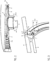
- the area of the bearing 7 and the rotary encoder 9 can be seen in detail. Accordingly, the rotary encoder 9 is preferably arranged on the bearing 7, in particular at a radial distance 19 from the center of the bearing cross-section of at most 0.2 m.
- the sensor 9a is preferably arranged in a stationary manner, for example on an outer bearing ring 7a which is connected to the frame 3.
- An associated measuring standard 9b for scanning by the sensor 9a is then formed on the support structure 6 or on an inner bearing ring 7b of the bearing 7 connected to it.
- the material measure 9b is preferably arranged on an outwardly facing cylinder jacket surface. Due to the arrangement of the rotary encoder 9 in the area 8 lying radially outside of the motor 5, the material measure 9b enables a comparatively fine angular resolution for determining the rotational position of the container table 4.
- the bearing 7 is preferably an axial-radial bearing and in particular a preloadable crossed roller bearing. During operation, the bearing 7 absorbs, for example, the clamping force transmitted from the centering bells 16 to the container 2 and the turntable 14.
- the rotary encoder 9 is preferably a so-called single-turn absolute encoder.
- the rotary encoder 9 preferably works on the principle of an inductive encoder or a capacitive encoder. Depending on the installation position of the rotary encoder 9, it can also work according to the principle of an optical encoder.
- the sensor 9a of the rotary encoder 9 is preferably accessible from below for maintenance measures, in particular for an exchange.
- the material measure 9b is preferably also accessible from below for maintenance measures, such as, for example, for checking and / or cleaning, and, in a preferred embodiment, can also be exchanged.
- the accuracy of the rotary encoder 9 is preferably ⁇ 20 ⁇ m absolute or better, that is, based on the origin of the measuring standard 9b.
- the pitch circle 4a preferably has a diameter of at least 1.5 m and in particular at least 1.8 m.
- the rotary encoder 9 By arranging the rotary encoder 9 in the area 8 radially outside the motor 5 and in particular in the area of the bearing 7, for example with a radial distance 19 of at most 0.2 m, the rotary encoder 9 can be connected close to the load.
- the lowest natural load frequency in the range of up to 10 Hz can be effectively suppressed.
- the motor 5, which is designed as an internal rotor enables a suppression of resonance frequencies in the range above 100 Hz due to the comparatively low motor inertia.
- Control loops for suppressing natural resonances in the drive unit 18 of the rotary machine 1 can therefore work more effectively, for example by giving priority to a range from 10 Hz to 100 Hz is amplitude controlled.
- the rotary encoder 9 is arranged directly on the bearing 7, as in FIG Fig. 3 is shown, particularly advantageous.
- the fastening of the sensor 9a to the stationary frame 3 simplifies both its electrical energy supply and the transmission of measurement signals.
- the stationary / circumferential fastening of the sensor 9a / the measuring standard 9b could also be interchanged.
- the motor 5 is preferably suspended from the frame 3 or the support structure 6 of the container table 4 in such a way that it is accessible from below for maintenance measures and can be removed downwards as a whole and / or in individual parts, for example the rotor 5b. A dismantling of the overlying container table 4 and / or its support structure 6 is then not necessary.
- Additional units for container handling which are docked in a stationary manner on the sub-frame 3, for example, are not shown for the sake of simplicity.
- the drive unit 18 described and the associated rotational position determination for the container table 4 can be used flexibly for different rotary machines for container treatment, for example for a direct printing machine, a labeling machine, a closer, a filler, a stretch blow molding machine, a rinser or an inspection machine.
- the internal rotor direct drive of the container table 4, so without an interposed gear or the like, allows with the radially outer rotary encoder 9 both with regard to the concentricity, the concentricity, the axial run-out and the parallelism to the Frame 3 advantageous mechanical running properties as well as a precise, control-technically simple and easy-to-maintain rotational position determination.
Landscapes
- Engineering & Computer Science (AREA)
- General Physics & Mathematics (AREA)
- Physics & Mathematics (AREA)
- Power Engineering (AREA)
- Mechanical Engineering (AREA)
- Health & Medical Sciences (AREA)
- Chemical & Material Sciences (AREA)
- Analytical Chemistry (AREA)
- Biochemistry (AREA)
- General Health & Medical Sciences (AREA)
- Immunology (AREA)
- Pathology (AREA)
- Life Sciences & Earth Sciences (AREA)
- Manufacturing & Machinery (AREA)
- Specific Conveyance Elements (AREA)
- Labeling Devices (AREA)
- Blow-Moulding Or Thermoforming Of Plastics Or The Like (AREA)
- Rolling Contact Bearings (AREA)
Description
- Die Erfindung betrifft eine Rundläufermaschine gemäß Oberbegriff des Anspruchs 1 bzw. 2.
- Gattungsgemäße Rundläufermaschinen zur Behandlung von Behältern sind aus der
DE 10 2013 218438 A1 bekannt. Zur direkten Drehlagenbestimmung des Behältertisches, also ohne indirekte Drehzahlmessung am Antriebsmotor und/oder einem zwischengeschalteten Getriebe, dient dabei ein zentral an der Mittelachse der Rundläufermaschine angeordneter Drehgeber. Der Antriebsmotor reicht in radialer Richtung über den Drehgeber hinaus. - Aus der
DE 2008 038 146 A1 ist ferner eine Rundläufermaschine bekannt, die mit Ausnahme einer radial innenliegenden Lagerung des Behältertisches bzw. seiner Tragstruktur gattungsgemäß ausgebildet ist. Der Drehgeber ist zweckmäßigerweise entweder direkt an einem unteren im Motor zugänglich platzierten Ende der Zentralwelle oder direkt am oberen Wellenende installiert. Es kann sich dabei um einen Drehimpulsgeber, einen Absolutwertgeber und/oder einen Mittendrehgeber handeln. Das Gebersystem kann jedoch auch seitlich am oder neben dem Motor angeordnet und mit dem Wellenende über einen Zahnriemen gekoppelt sein. - Da Rundläufermaschinen mit immer größeren Teilkreisdurchmessern benötigt werden und Drehgeber für Instandhaltungsmaßnahmen gut zugänglich sein sollen, besteht zunehmend Bedarf für eine präzisere Drehlagenbestimmung und einen verbesserten Zugang zu Antriebskomponenten und Drehgebern des Behältertisches.
- Die gestellte Aufgabe wird mit einer Rundläufermaschine zur Behandlung von Behältern gemäß Anspruch 1 bzw. 2 gelöst. Demnach umfasst die Rundläufermaschine ein feststehendes Untergestell, einen drehbaren Behältertisch zur Aufnahme der Behälter, einen als Innenläufer ausgebildeten Motor zum Direktantrieb des Behältertisches, ein Lager zum Abstützen des Behältertisches und/oder einer drehfest mit dem Behältertisch verbundenen Tragstruktur am Untergestell radial außerhalb des Motors, und einen Drehgeber zur Drehlagenbestimmung des Behältertisches.
- Dadurch, dass der Drehgeber radial außerhalb des Motors angeordnet ist, lässt sich sowohl die Genauigkeit des Drehgebers, insbesondere dessen Winkelauflösung, als auch die Zugänglichkeit des Drehgebers für Instandhaltungsmaßnahmen gegenüber einem zentral in dem Bereich des Motors angeordneten Drehgeber verbessern.
- Der Drehgeber besteht aus wenigstens einem Sensor und wenigstens einer vom Sensor abgetasteten Maßverkörperung.
- Unter einer Anordnung radial außerhalb des Motors ist zu verstehen, dass sowohl Sensor als auch Maßverkörperung radial außerhalb des Stators und des Rotors des Motors angeordnet sind.
- Der Drehgeber umfasst demnach entweder: einen feststehenden und mit dem Untergestell verbundenen Sensor und eine am Behältertisch oder an der Tragstruktur ausgebildete / befestigte Maßverkörperung für den Sensor; oder einen am Behältertisch oder an der Tragstruktur ausgebildeten / befestigten Sensor und eine feststehende und mit dem Untergestell verbundene Maßverkörperung für den Sensor.
- Bei einem Innenläufer sind der Behältertisch und/oder seine Tragstruktur mit dem innen liegenden Rotor des Motors verbunden.
- Das Lager ist zur Aufnahme der im Arbeitsbetrieb auftretenden Axialkräfte und Radialkräfte ausgebildet.
- Vorzugsweise ist der Drehgeber im Bereich des Behältertisches und/oder der Tragstruktur in einem radialen Abstand von weniger als 0,2 m vom Lager angeordnet. Dies ermöglicht eine schwingungsarme und damit genauere Messung der Drehlage infolge einer erhöhten mechanischen Stabilität in der Nachbarschaft des Lagers. Die radiale Position des Lagers wird beispielsweise durch den Mittelpunkt des Lagerquerschnitts vorgegeben.
- Umfasst der Drehgeber einen feststehenden Sensor, so werden die elektrische Stromversorgung und das Auslesen von Messdaten vereinfacht.
- Umfasst der Drehgeber eine am Behältertisch und/oder Tragstruktur ausgebildete und/oder befestigte Maßverkörperung für den Sensor, so lässt sich die Maßverkörperung in geeignetem radialen Abstand von der Mittelachse des Behältertisches anordnen.
- Vorzugsweise ist die Maßverkörperung unterhalb und/oder radial außerhalb des Lagers angeordnet. Dies erhöht die Präzision der Drehlagenbestimmung und erleichtert den Zugang zum Drehgeber für Instandhaltungsmaßnahmen.
- Vorzugsweise ist der Motor ein Torquemotor. Vorzugsweise ist das Lager ein Axial-Radial-Lager und insbesondere ein Kreuzrollenlager. Dies ermöglicht beispielsweise ein Vorspannen des Lagers zur Minimierung von Planlauf-Abweichungen des Behältertisches und/oder Parallelität-Abweichungen zwischen Behältertisch und Untergestell.
- Vorzugsweise weist das Lager eine Planlauf-Abweichung von höchstens 0,015 mm zum Behältertisch hin auf und/oder eine Parallelitäts-Abweichung von höchstens 0,15 mm zum Behältertisch und zum Untergestellt hin auf. Damit lässt sich eine präzise Behälterbehandlung auch bei Teilkreisdurchmessern von wenigstens 1,5 m erzielen.
- Vorzugsweise hat der Behältertisch einen Teilkreisdurchmesser von 1,5 bis 2,5 m. Damit lassen sich Behälter mit vergleichsweise hoher Maschinenleistung behandeln. Eine Drehlagenmessung radial außerhalb des Motors ist dann besonders vorteilhaft für eine präzise Behandlung.
- Vorzugsweise ist das Lager radial zwischen dem Motor und dem Teilkreis des Behältertisches angeordnet. Das Lager liegt dann insbesondere radial innerhalb von Antriebsmotoren für Drehteller zur Aufnahme der Behälter. Dies begünstigt eine mechanisch stabile und dennoch kompakte Bauweise der Rundläufermaschine.
- Vorzugsweise ist die Rundläufermaschine als Direktdruckmaschine, Etikettiermaschine, Verschließer, Füller, Streckblasmaschine, Rinser, Inspektionsmaschine oder andere Behälterbehandlungsmaschine ausgebildet. Die präzise Drehlagenbestimmung des zugehörigen Behältertisches dient einem präzisen Zusammenwirken mit den jeweils an der Rundläufermaschine vorhandenen Behandlungsaggregaten. Diese können beispielsweise stationär angedockt sein und/oder am Behältertisch umlaufen. Zudem ist der Zugang zum Drehgeber beispielsweise für Kontrolle und/oder Ersatz der Sensoren und/oder der Maßverkörperung je nach Instandhaltungsintervallen erleichtert.
- Vorzugsweise ist der Stator des Motors hängend und nach unten hin lösbar am Untergestell befestigt. Dies erleichtert Instandhaltungsmaßnahmen am Motor.
- Vorzugsweise ist der Rotor des Motors als Hohlwelle ausgebildet und/oder umgibt eine Hohlwelle. Die Hohlwelle kann dann für Medienverbindungen zwischen dem feststehenden Teil und dem rotierenden Teil der Rundläufermaschine verwendet werden.
- Vorzugsweise sind dann innerhalb der Hohlwelle Leitungen zur Medienversorgung, insbesondere zur Energieversorgung, Druckgasversorgung oder dergleichen, des Behältertisches und/oder eines mit dem Behältertisch drehfest verbundenen Maschinenoberteils angeordnet.
- Bevorzugte Ausführungsformen der Erfindung sind zeichnerisch dargestellt. Es zeigen:
- Fig. 1
- einen schematischen Längsschnitt durch eine Rundläufermaschine;
- Fig. 2
- eine mögliche Ausgestaltung eines Behältertisches mit Lager und Motor; und
- Fig. 3
- eine Detailansicht des Behältertisches der
Fig. 2 mit einem Drehgeber. - Wie die
Fig. 1 erkennen lässt, umfasst die Rundläufermaschine 1 zur Behandlung von Behältern 2 ein feststehendes Untergestell 3, einen drehbaren Behältertisch 4 zur Aufnahme der Behälter 2 auf einem Teilkreis 4a und einen als Innenläufer ausgebildeten Motor 5 zum Direktantrieb des Behältertisches 4. Dieser kann dadurch um eine zentrale Mittelachse 1a der Rundläufermaschine 1 insbesondere kontinuierlich gedreht werden. - Der Motor 5 ist insbesondere ein Torquemotor mit einem außenliegenden Stator 5a und einem innenliegenden Rotor 5b.
- Der Motor 5 ist mit dem Behältertisch 4 mittels einer Tragstruktur 6 verbunden. Dies ist in der
Fig. 1 lediglich schematisch angedeutet. Die Tragstruktur 6 umfasst beispielsweise einen zentralen Verbindungsabschnitt 6a zur drehfesten Ankopplung an den Rotor 5b. Ferner umfasst die Tragstruktur 6 vorzugsweise einen äußeren Tragabschnitt 6b zur drehfesten Ankopplung und Abstützung des Behältertisches 4. - Die Tragstruktur 6 stützt sich mittels eines ringförmigen Lagers 7 auf dem stationären Untergestell 3 ab. Das Lager 7 ist insbesondere ein Axial-Radial-Lager zur Aufnahme von Axialkräften und Radialkräften während der Behandlung der Behälter 2.
- Das Lager 7 stützt den Behältertisch 4 und/oder die Tragstruktur 6 in einem radial außerhalb des Motors 5 liegenden Bereich 8 ab, der beispielsweise bezüglich des Außenumfangs des Stators 5a definiert ist.
- Im radial außenliegenden Bereich 8 ist ferner ein Drehgeber 9 für den Behältertisch 4 vorhanden. Der Drehgeber 9 umfasst vorzugsweise einen feststehenden / mit dem Untergestell 3 verbundenen Sensor 9a und eine am Behältertisch 4 oder an der Tragstruktur 6 ausgebildete / befestigte Maßverkörperung 9b für den Sensor 9a. Die Maßverkörperung 9a ist ein vollumfänglich ausgebildeter Längenmaßstab / Winkelmaßstab mit einem vom Sensor 9a erkennbaren Ursprung und wird vom Sensor 9a vorzugsweise berührungslos abgetastet.
- Der Sensors 9a ist zur Übertragung von Drehlagendaten des Behältertisches 4 mit einer schematisch angedeuteten Steuerung 10 verbunden. Dies ist drahtlos oder drahtgebunden möglich.
- Zur vereinfachten Medienanbindung eines schematisch angedeuteten Maschinenoberteils 12 der Rundläufermaschine 1 umfasst und/oder umschließt der Rotor 5b des Motors 5 vorzugsweise einen zentralen Kanal 13, der in der
Fig. 1 lediglich schematisch angedeutet ist. Der zentrale Kanal 13 eignet sich für die Medienversorgung des Behältertisches 4 und/oder des Maschinenoberteils 12. Im Kanal 13 können Medienleitungen, Datenleitungen oder dergleichen vom stationären zum rotierenden Teil der Rundläufermaschine 1 geführt werden. - In der
Fig. 1 sind schematisch ferner Drehteller 14 zur Aufnahme der Behälter 2, individuelle Antriebsmotoren 15 für die Drehteller 14 und Zentrierglocken 16 zum Einspannen der Behälter 2 auf den Drehtellern 14 dargestellt sowie eine Hubkurve 17 zum Absenken der Zentrierglocken 16 auf die Behälter 2. - Die
Fig. 2 verdeutlicht eine konkrete Ausgestaltung einer Antriebseinheit 18 der Rundläufermaschine 1 mit dem Behältertisch 4, dem Motor 5 mit Stator 5a und Rotor 5b, der Tragstruktur 6, dem Lager 7 und dem Drehgeber 9. Zu erkennen sind ferner die Antriebsmotoren 15 für die Drehteller 14. - In der
Fig. 3 ist der Bereich des Lagers 7 und des Drehgebers 9 im Detail zu erkennen. Demnach ist der Drehgeber 9 vorzugsweise am Lager 7 angeordnet, insbesondere in einem radialen Abstand 19 vom Mittelpunkt des Lagerquerschnitts von höchstens 0,2 m. - Der Sensor 9a ist vorzugsweise feststehend angeordnet, beispielsweise an einem äußeren Lagerring 7a, der mit dem Gestell 3 verbunden ist. An der Tragstruktur 6 oder einem damit verbundenen inneren Lagerring 7b des Lagers 7 ist dann eine zugehörige Maßverkörperung 9b zur Abtastung durch den Sensor 9a ausgebildet.
- Die Maßverkörperung 9b ist vorzugsweise auf einer nach außen weisenden Zylindermantelfläche angeordnet. Aufgrund der Anordnung des Drehgebers 9 in dem radial außerhalb des Motors 5 liegenden Bereich 8 ermöglicht die Maßverkörperung 9b eine vergleichsweise feine Winkelauflösung zur Drehlagenbestimmung des Behältertisches 4.
- Wie insbesondere in der
Fig. 3 zu erkennen ist, ist das Lager 7 vorzugsweise ein Axial-Radial-Lager und insbesondere ein vorspannbares Kreuzrollenlager. Das Lager 7 nimmt im Arbeitsbetrieb beispielsweise die von den Zentrierglocken 16 an die Behälter 2 und die Drehteller 14 übertragene Einspannkraft auf. - Der Drehgeber 9 ist vorzugsweise ein sogenannter Singleturn-Absolutwertgeber. Der Drehgeber 9 arbeitet vorzugsweise nach dem Prinzip eines induktiven Gebers oder eines kapazitiven Gebers. Je nach Einbaulage des Drehgebers 9 kann dieser aber auch nach dem Prinzip eines optischen Gebers arbeiten.
- Der Sensor 9a des Drehgebers 9 ist vorzugsweise von unten her für Instandhaltungsmaßnahme, insbesondere für einen Austausch zugänglich.
- Die Maßverkörperung 9b ist vorzugsweise ebenso von unten her für Instandhaltungsmaßnahmen, wie beispielsweise zur Kontrolle und/oder Reinigung, von unten her zugänglich und in einer bevorzugten Ausführungsform zudem austauschbar.
- Die Genauigkeit des Drehgebers 9 beträgt vorzugsweise ± 20 µm absolut oder besser, also bezogen auf den Ursprung der Maßverkörperung 9b.
- Der Teilkreis 4a hat vorzugsweise einen Durchmesser von wenigstens 1,5 m und insbesondere wenigstens 1,8 m.
- Durch eine Anordnung des Drehgebers 9 im Bereich 8 radial außerhalb des Motors 5 und insbesondere im Bereich des Lagers 7, wie beispielsweise mit einem radialen Abstand 19 von höchstens 0,2 m, kann eine lastnahe Anbindung des Drehgebers 9 verwirklicht werden.
- Dadurch lässt sich beispielsweise die niedrigste Lasteigenfrequenz im Bereich bis 10 Hz wirksam unterdrücken. Ferner ermöglicht der als Innenläufer ausgebildete Motor 5 aufgrund vergleichsweise geringer Motorträgheit eine Unterdrückung von Resonanzfrequenzen im Bereich oberhalb 100 Hz. Regelkreise zur Unterdrückung von Eigenresonanzen in der Antriebseinheit 18 der Rundläufermaschine 1 können daher effektiver arbeiten, beispielsweise indem vorrangig ein Bereich von 10 Hz bis 100 Hz amplitudengeregelt wird.
- Auch aus diesem Grund ist eine Anordnung des Drehgebers 9 direkt am Lager 7, wie in der
Fig. 3 dargestellt ist, besonders vorteilhaft. Hierbei vereinfacht die Befestigung des Sensors 9a am feststehenden Gestell 3 sowohl dessen elektrische Energieversorgung als auch die Übermittlung von Messsignalen. Prinzipiell könnte man die stationäre / umlaufende Befestigung des Sensors 9a / der Maßverkörperung 9b aber auch miteinander vertauschen. - Der Motor 5 ist vorzugsweise so am Gestell 3 bzw. der Tragstruktur 6 des Behältertisches 4 aufgehängt, dass er für Instandhaltungsmaßnahmen von unten her zugänglich ist und sich als Ganzes und/oder in Einzelteilen, beispielsweise der Rotor 5b, nach unten hin ausbauen lässt. Eine Demontage des darüber liegenden Behältertisches 4 und/oder seiner Tragstruktur 6 ist dann dafür nicht nötig.
- Zusätzliche Aggregate für die Behälterbehandlung, die beispielsweise stationär am Untergestellt 3 angedockt werden, sind der Einfachheit halber nicht dargestellt. Die beschriebene Antriebseinheit 18und die zugehörige Drehlagenbestimmung für den Behältertisch 4 können flexibel für unterschiedliche Rundläufermaschinen zur Behälterbehandlung eingesetzt werden, beispielsweise für eine Direktdruckmaschine, eine Etikettiermaschine, einen Verschließer, einen Füller, eine Streckblasmaschine, einen Rinser oder eine Inspektionsmaschine.
- Der Innenläufer-Direktantrieb des Behältertisches 4, also ohne zwischengeschaltetes Getriebe oder dergleichen, ermöglicht mit dem radial außen liegenden Drehgeber 9 sowohl hinsichtlich der Konzentrizität, der Rundlaufgenauigkeit, des Planlaufs und der Parallelität zum Gestell 3 vorteilhafte mechanische Laufeigenschaften als auch eine präzise, regelungstechnisch einfache und gut zu wartende Drehlagenbestimmung.
Claims (13)
- Rundläufermaschine (1) zur Behandlung von Behältern (2), umfassend: ein feststehendes Untergestell (3); einen drehbaren Behältertisch (4) zur Aufnahme der Behälter (2); einen als Innenläufer ausgebildeten Motor (5) zum Direktantrieb des Behältertisches (4); ein Lager (7) zum Abstützen des Behältertisches (4) und/oder einer drehfest damit verbundenen Tragstruktur (6) am Untergestell (3) radial außerhalb des Motors (5); und einen Drehgeber (9) zur Drehlagenbestimmung des Behältertisches (4), dadurch gekennzeichnet, dass der Drehgeber (9) einen feststehenden und mit dem Untergestell (3) verbundenen Sensor (9a) und eine am Behältertisch (4) oder an der Tragstruktur (6) ausgebildete / befestigte Maßverkörperung (9b) für den Sensor (9a) umfasst und radial außerhalb des Motors (5) angeordnet ist.
- Rundläufermaschine (1) zur Behandlung von Behältern (2), umfassend: ein feststehendes Untergestell (3); einen drehbaren Behältertisch (4) zur Aufnahme der Behälter (2); einen als Innenläufer ausgebildeten Motor (5) zum Direktantrieb des Behältertisches (4); ein Lager (7) zum Abstützen des Behältertisches (4) und/oder einer drehfest damit verbundenen Tragstruktur (6) am Untergestell (3) radial außerhalb des Motors (5); und einen Drehgeber (9) zur Drehlagenbestimmung des Behältertisches (4), dadurch gekennzeichnet, dass der Drehgeber (9) einen am Behältertisch (4) oder an der Tragstruktur (6) ausgebildeten / befestigten Sensor (9a) und eine feststehende und mit dem Untergestell (3) verbundene Maßverkörperung (9b) für den Sensor (9a) umfasst und radial außerhalb des Motors (5) angeordnet ist.
- Rundläufermaschine nach Anspruch 1 oder 2, wobei der Drehgeber (9) im Bereich des Behältertisches (4) und/oder der Tragstruktur (6) in einem radialen Abstand (19) von weniger als 0,2 m vom Lager (7) angeordnet ist.
- Rundläufermaschine nach Anspruch 1, wobei die Maßverkörperung (9b) unterhalb und/oder radial außerhalb des Lagers (7) angeordnet ist.
- Rundläufermaschine nach wenigstens einem der vorigen Ansprüche, wobei der Motor (5) ein Torquemotor ist.
- Rundläufermaschine nach wenigstens einem der vorigen Ansprüche, wobei das Lager (7) ein Axial-Radial-Lager und insbesondere ein Kreuzrollenlager ist.
- Rundläufermaschine nach wenigstens einem der vorigen Ansprüche, wobei das Lager (7) eine Planlauf-Abweichung von höchstens 0,015 mm zum Behältertisch (4) hin aufweist und/oder eine Parallelität-Abweichung von höchstens 0,15 mm zum Behältertisch (4) und zum Untergestell (3) hin.
- Rundläufermaschine nach wenigstens einem der vorigen Ansprüche, wobei der Behältertisch (4) einen Teilkreisdurchmesser (4a) von 1,5 bis 2,5 m hat.
- Rundläufermaschine nach wenigstens einem der vorigen Ansprüche, wobei das Lager (7) radial zwischen dem Motor (5) und dem Teilkreis (4a) des Behältertisches (4) angeordnet ist.
- Rundläufermaschine nach wenigstens einem der vorigen Ansprüche, die als Direktdruckmaschine, Etikettiermaschine, Verschließer, Füller, Streckblasmaschine, Rinser oder Inspektionsmaschine ausgebildet ist.
- Rundläufermaschine nach wenigstens einem der vorigen Ansprüche, wobei der Stator (5a) des Motors (5) hängend und nach unten hin lösbar am Untergestell (3) befestigt ist.
- Rundläufermaschine nach wenigstens einem der vorigen Ansprüche, wobei der Rotor (5b) des Motors (5) einen zentralen Kanal (13) umfasst und/oder umgibt.
- Rundläufermaschine nach Anspruch 12, wobei innerhalb des Kanals (13) Leitungen zur Medienversorgung, insbesondere Energieversorgung, des Behältertisches (4) und/oder eines mit dem Behältertisch (4) drehfest verbundenen Maschinenoberteils (12) angeordnet sind.
Applications Claiming Priority (1)
| Application Number | Priority Date | Filing Date | Title |
|---|---|---|---|
| DE102017215443.8A DE102017215443A1 (de) | 2017-09-04 | 2017-09-04 | Rundläufermaschine zur Behandlung von Behältern |
Publications (2)
| Publication Number | Publication Date |
|---|---|
| EP3451513A1 EP3451513A1 (de) | 2019-03-06 |
| EP3451513B1 true EP3451513B1 (de) | 2021-06-23 |
Family
ID=62104178
Family Applications (1)
| Application Number | Title | Priority Date | Filing Date |
|---|---|---|---|
| EP18170332.3A Active EP3451513B1 (de) | 2017-09-04 | 2018-05-02 | Rundläufermaschine zur behandlung von behältern |
Country Status (4)
| Country | Link |
|---|---|
| US (1) | US11117699B2 (de) |
| EP (1) | EP3451513B1 (de) |
| CN (1) | CN109421975B (de) |
| DE (1) | DE102017215443A1 (de) |
Families Citing this family (1)
| Publication number | Priority date | Publication date | Assignee | Title |
|---|---|---|---|---|
| DE102023110378A1 (de) | 2023-04-24 | 2024-10-24 | Gasti Verpackungsmaschinen Gmbh | Vorrichtung vom rundläufer-typ zum abfüllen von einem füllmedium in eine vielzahl von behälter |
Family Cites Families (19)
| Publication number | Priority date | Publication date | Assignee | Title |
|---|---|---|---|---|
| JP2000344477A (ja) * | 1999-06-02 | 2000-12-12 | Ebara Corp | 水圧駆動式昇降割出装置 |
| US8261631B2 (en) * | 2002-09-23 | 2012-09-11 | Computrol, Inc. | Rotary machine with separately controllable stations |
| DE102004054891A1 (de) * | 2004-11-12 | 2006-05-24 | Khs Ag | Flaschenteller |
| ES2387036T3 (es) * | 2006-06-06 | 2012-09-12 | Sidel Holdings & Technology S.A. | Máquina etiquetadora |
| DE102007031218B4 (de) * | 2006-07-05 | 2020-10-29 | Sew-Eurodrive Gmbh & Co Kg | Vorrichtung, Etikettiermaschine und Verfahren zum Betreiben einer Vorrichtung |
| US8439338B2 (en) * | 2008-02-29 | 2013-05-14 | Thk Co., Ltd. | Rotary table device provided with cooling structure and rotary bearing provided with cooling structure |
| DE102008012757A1 (de) * | 2008-03-05 | 2009-09-10 | Krones Ag | Vorrichtung zum Erzeugen von Kunststoffbehältnissen |
| DE102008038146A1 (de) * | 2008-08-18 | 2010-02-25 | Krones Ag | Vorrichtung zum Behandeln von Behältern |
| DE102008062064A1 (de) * | 2008-12-12 | 2010-06-17 | Krones Ag | Verfahren zur Steuerung einer Maschine zur Behandlung von Behältern |
| DE102009005180A1 (de) * | 2009-01-15 | 2010-07-22 | Khs Ag | Behälterbehandlungsmaschine |
| JP5294016B2 (ja) * | 2009-01-30 | 2013-09-18 | 株式会社ニイガタマシンテクノ | 回転テーブルの振れ制御装置及びこれを備えた工作機械、回転テーブルの振れ制御方法 |
| DE102009035880B4 (de) * | 2009-08-03 | 2012-02-02 | Khs Gmbh | Behandlungsmaschine zum Behandeln von Packmitteln und Verfahren zum ausgerichteten Andocken eines Behandlungsmoduls an eine Behandlungsmaschine |
| EP2648982A1 (de) * | 2010-12-10 | 2013-10-16 | Sidel S.p.A. | Maschine für artikelhandhabung |
| DE102012204721A1 (de) * | 2012-03-23 | 2013-09-26 | Schaeffler Technologies AG & Co. KG | Direktantrieb für eine Rotationsmaschine, insbesondere für eine Behälterbehandlungsmaschine |
| DE102012213080A1 (de) * | 2012-07-25 | 2014-01-30 | Krones Ag | Vorrichtung und Verfahren zum Ausstattung von Behältern - Basismaschine |
| DE102013208065A1 (de) * | 2013-05-02 | 2013-07-04 | Krones Ag | Rundläufermaschine zur Bedruckung von Behältern |
| DE202013008100U1 (de) * | 2013-09-12 | 2013-10-22 | Krones Ag | Etikettiermaschine |
| DE102013218438A1 (de) * | 2013-09-13 | 2015-03-19 | Krones Ag | Rundläufermaschine mit Direktantrieb |
| DE102014000690A1 (de) * | 2014-01-17 | 2015-07-23 | Kienle + Spiess Gmbh | Ringförmiges Lamellenpaket aus Einzelzahnpaketen sowie Verfahren zur Herstellung eines Lamellenpaketes |
-
2017
- 2017-09-04 DE DE102017215443.8A patent/DE102017215443A1/de not_active Withdrawn
-
2018
- 2018-05-02 EP EP18170332.3A patent/EP3451513B1/de active Active
- 2018-08-09 US US16/059,894 patent/US11117699B2/en active Active
- 2018-08-16 CN CN201810935980.2A patent/CN109421975B/zh active Active
Non-Patent Citations (1)
| Title |
|---|
| None * |
Also Published As
| Publication number | Publication date |
|---|---|
| CN109421975A (zh) | 2019-03-05 |
| DE102017215443A1 (de) | 2019-03-07 |
| US20190071203A1 (en) | 2019-03-07 |
| CN109421975B (zh) | 2022-02-15 |
| EP3451513A1 (de) | 2019-03-06 |
| US11117699B2 (en) | 2021-09-14 |
Similar Documents
| Publication | Publication Date | Title |
|---|---|---|
| DE4219318C2 (de) | Verfahren und Vorrichtung zum Bestimmen des Kontaktwinkels von Kugellagern | |
| DE4444992C2 (de) | Vorrichtung zum Unwuchtausgleich von Rotationskörpern, insbesondere von Schleifscheiben | |
| DE202014011033U1 (de) | Messvorrichtung | |
| DE102006039090A1 (de) | Antrieb für Rotationsmaschinen | |
| EP3293495A1 (de) | Maschine mit gekühlter hohlwelle und konzentrischem drehgeber | |
| EP2581553B9 (de) | Verfahren und Vorrichtung zum dynamischen Messen der Unwucht des Rotors einer Turbolader-Rumpfgruppe | |
| EP3451513A1 (de) | Rundläufermaschine zur behandlung von behältern | |
| WO1987002148A1 (fr) | Systeme d'entrainement pour un miroir pivotant rotatif | |
| DE102010036954B4 (de) | Verfahren und Vorrichtung zum dynamischen Messen der Unwucht des Rotors einer Turbolader-Rumpfgruppe | |
| EP2463646A1 (de) | Inspektionsträger für Behälter | |
| JP2003528302A (ja) | 距離測定方法及び装置 | |
| DE102021114443B4 (de) | Prüfkopf für einen Fingertester sowie Fingertester mit mehreren solcher Prüfköpfe und Verfahren zum Testen von Leiterplatten | |
| DE102014212822A1 (de) | Reifenprüfmaschine | |
| EP2755790B1 (de) | Honverfahren mit einmittung eines werkstücks an einer wälzprüfstation | |
| US20090266112A1 (en) | Circular knitting machine with a rotatably disposed dial | |
| EP0406720A1 (de) | Spindel mit Elektromotorischen Einzelantrieb | |
| JP5937952B2 (ja) | 綱車主索溝摩耗測定方法 | |
| JP5748052B2 (ja) | 長尺ノズル内面加工装置 | |
| WO2017005472A1 (de) | Antriebsanordnung für eine schwenkbrücke | |
| EP1129847A1 (de) | Antrieb für Zylinder einer Druckmaschine | |
| DE102008025027B4 (de) | Verfahren und Vorrichtung zur Kompensierung von Rundlauffehlern eines Drehwinkel erfassenden Sensors | |
| WO2015169823A1 (de) | Vorrichtung zur drehbaren lagerung von werkstücken, insbesondere kurbelwellen | |
| CN108489670B (zh) | 离心叶轮静平衡自动调试机 | |
| EP3387406B1 (de) | Radkraftdynamometer zur messung von reifenkräften | |
| DE102024105651A1 (de) | System, umfassend ein Zahnrad und eine Prüfmaschine |
Legal Events
| Date | Code | Title | Description |
|---|---|---|---|
| PUAI | Public reference made under article 153(3) epc to a published international application that has entered the european phase |
Free format text: ORIGINAL CODE: 0009012 |
|
| STAA | Information on the status of an ep patent application or granted ep patent |
Free format text: STATUS: THE APPLICATION HAS BEEN PUBLISHED |
|
| AK | Designated contracting states |
Kind code of ref document: A1 Designated state(s): AL AT BE BG CH CY CZ DE DK EE ES FI FR GB GR HR HU IE IS IT LI LT LU LV MC MK MT NL NO PL PT RO RS SE SI SK SM TR |
|
| AX | Request for extension of the european patent |
Extension state: BA ME |
|
| STAA | Information on the status of an ep patent application or granted ep patent |
Free format text: STATUS: REQUEST FOR EXAMINATION WAS MADE |
|
| 17P | Request for examination filed |
Effective date: 20190808 |
|
| RBV | Designated contracting states (corrected) |
Designated state(s): AL AT BE BG CH CY CZ DE DK EE ES FI FR GB GR HR HU IE IS IT LI LT LU LV MC MK MT NL NO PL PT RO RS SE SI SK SM TR |
|
| STAA | Information on the status of an ep patent application or granted ep patent |
Free format text: STATUS: EXAMINATION IS IN PROGRESS |
|
| 17Q | First examination report despatched |
Effective date: 20200603 |
|
| GRAP | Despatch of communication of intention to grant a patent |
Free format text: ORIGINAL CODE: EPIDOSNIGR1 |
|
| STAA | Information on the status of an ep patent application or granted ep patent |
Free format text: STATUS: GRANT OF PATENT IS INTENDED |
|
| INTG | Intention to grant announced |
Effective date: 20210201 |
|
| GRAS | Grant fee paid |
Free format text: ORIGINAL CODE: EPIDOSNIGR3 |
|
| GRAA | (expected) grant |
Free format text: ORIGINAL CODE: 0009210 |
|
| STAA | Information on the status of an ep patent application or granted ep patent |
Free format text: STATUS: THE PATENT HAS BEEN GRANTED |
|
| AK | Designated contracting states |
Kind code of ref document: B1 Designated state(s): AL AT BE BG CH CY CZ DE DK EE ES FI FR GB GR HR HU IE IS IT LI LT LU LV MC MK MT NL NO PL PT RO RS SE SI SK SM TR |
|
| REG | Reference to a national code |
Ref country code: GB Ref legal event code: FG4D Free format text: NOT ENGLISH |
|
| REG | Reference to a national code |
Ref country code: CH Ref legal event code: EP |
|
| REG | Reference to a national code |
Ref country code: DE Ref legal event code: R096 Ref document number: 502018005788 Country of ref document: DE Ref country code: AT Ref legal event code: REF Ref document number: 1405165 Country of ref document: AT Kind code of ref document: T Effective date: 20210715 |
|
| REG | Reference to a national code |
Ref country code: IE Ref legal event code: FG4D Free format text: LANGUAGE OF EP DOCUMENT: GERMAN |
|
| REG | Reference to a national code |
Ref country code: LT Ref legal event code: MG9D |
|
| PG25 | Lapsed in a contracting state [announced via postgrant information from national office to epo] |
Ref country code: BG Free format text: LAPSE BECAUSE OF FAILURE TO SUBMIT A TRANSLATION OF THE DESCRIPTION OR TO PAY THE FEE WITHIN THE PRESCRIBED TIME-LIMIT Effective date: 20210923 Ref country code: LT Free format text: LAPSE BECAUSE OF FAILURE TO SUBMIT A TRANSLATION OF THE DESCRIPTION OR TO PAY THE FEE WITHIN THE PRESCRIBED TIME-LIMIT Effective date: 20210623 Ref country code: HR Free format text: LAPSE BECAUSE OF FAILURE TO SUBMIT A TRANSLATION OF THE DESCRIPTION OR TO PAY THE FEE WITHIN THE PRESCRIBED TIME-LIMIT Effective date: 20210623 Ref country code: FI Free format text: LAPSE BECAUSE OF FAILURE TO SUBMIT A TRANSLATION OF THE DESCRIPTION OR TO PAY THE FEE WITHIN THE PRESCRIBED TIME-LIMIT Effective date: 20210623 |
|
| PG25 | Lapsed in a contracting state [announced via postgrant information from national office to epo] |
Ref country code: LV Free format text: LAPSE BECAUSE OF FAILURE TO SUBMIT A TRANSLATION OF THE DESCRIPTION OR TO PAY THE FEE WITHIN THE PRESCRIBED TIME-LIMIT Effective date: 20210623 Ref country code: NO Free format text: LAPSE BECAUSE OF FAILURE TO SUBMIT A TRANSLATION OF THE DESCRIPTION OR TO PAY THE FEE WITHIN THE PRESCRIBED TIME-LIMIT Effective date: 20210923 Ref country code: SE Free format text: LAPSE BECAUSE OF FAILURE TO SUBMIT A TRANSLATION OF THE DESCRIPTION OR TO PAY THE FEE WITHIN THE PRESCRIBED TIME-LIMIT Effective date: 20210623 Ref country code: RS Free format text: LAPSE BECAUSE OF FAILURE TO SUBMIT A TRANSLATION OF THE DESCRIPTION OR TO PAY THE FEE WITHIN THE PRESCRIBED TIME-LIMIT Effective date: 20210623 Ref country code: GR Free format text: LAPSE BECAUSE OF FAILURE TO SUBMIT A TRANSLATION OF THE DESCRIPTION OR TO PAY THE FEE WITHIN THE PRESCRIBED TIME-LIMIT Effective date: 20210924 |
|
| REG | Reference to a national code |
Ref country code: NL Ref legal event code: MP Effective date: 20210623 |
|
| PG25 | Lapsed in a contracting state [announced via postgrant information from national office to epo] |
Ref country code: PT Free format text: LAPSE BECAUSE OF FAILURE TO SUBMIT A TRANSLATION OF THE DESCRIPTION OR TO PAY THE FEE WITHIN THE PRESCRIBED TIME-LIMIT Effective date: 20211025 Ref country code: NL Free format text: LAPSE BECAUSE OF FAILURE TO SUBMIT A TRANSLATION OF THE DESCRIPTION OR TO PAY THE FEE WITHIN THE PRESCRIBED TIME-LIMIT Effective date: 20210623 Ref country code: RO Free format text: LAPSE BECAUSE OF FAILURE TO SUBMIT A TRANSLATION OF THE DESCRIPTION OR TO PAY THE FEE WITHIN THE PRESCRIBED TIME-LIMIT Effective date: 20210623 Ref country code: CZ Free format text: LAPSE BECAUSE OF FAILURE TO SUBMIT A TRANSLATION OF THE DESCRIPTION OR TO PAY THE FEE WITHIN THE PRESCRIBED TIME-LIMIT Effective date: 20210623 Ref country code: SM Free format text: LAPSE BECAUSE OF FAILURE TO SUBMIT A TRANSLATION OF THE DESCRIPTION OR TO PAY THE FEE WITHIN THE PRESCRIBED TIME-LIMIT Effective date: 20210623 Ref country code: SK Free format text: LAPSE BECAUSE OF FAILURE TO SUBMIT A TRANSLATION OF THE DESCRIPTION OR TO PAY THE FEE WITHIN THE PRESCRIBED TIME-LIMIT Effective date: 20210623 Ref country code: ES Free format text: LAPSE BECAUSE OF FAILURE TO SUBMIT A TRANSLATION OF THE DESCRIPTION OR TO PAY THE FEE WITHIN THE PRESCRIBED TIME-LIMIT Effective date: 20210623 Ref country code: EE Free format text: LAPSE BECAUSE OF FAILURE TO SUBMIT A TRANSLATION OF THE DESCRIPTION OR TO PAY THE FEE WITHIN THE PRESCRIBED TIME-LIMIT Effective date: 20210623 |
|
| PG25 | Lapsed in a contracting state [announced via postgrant information from national office to epo] |
Ref country code: PL Free format text: LAPSE BECAUSE OF FAILURE TO SUBMIT A TRANSLATION OF THE DESCRIPTION OR TO PAY THE FEE WITHIN THE PRESCRIBED TIME-LIMIT Effective date: 20210623 |
|
| REG | Reference to a national code |
Ref country code: DE Ref legal event code: R097 Ref document number: 502018005788 Country of ref document: DE |
|
| PG25 | Lapsed in a contracting state [announced via postgrant information from national office to epo] |
Ref country code: DK Free format text: LAPSE BECAUSE OF FAILURE TO SUBMIT A TRANSLATION OF THE DESCRIPTION OR TO PAY THE FEE WITHIN THE PRESCRIBED TIME-LIMIT Effective date: 20210623 |
|
| PLBE | No opposition filed within time limit |
Free format text: ORIGINAL CODE: 0009261 |
|
| STAA | Information on the status of an ep patent application or granted ep patent |
Free format text: STATUS: NO OPPOSITION FILED WITHIN TIME LIMIT |
|
| 26N | No opposition filed |
Effective date: 20220324 |
|
| PG25 | Lapsed in a contracting state [announced via postgrant information from national office to epo] |
Ref country code: AL Free format text: LAPSE BECAUSE OF FAILURE TO SUBMIT A TRANSLATION OF THE DESCRIPTION OR TO PAY THE FEE WITHIN THE PRESCRIBED TIME-LIMIT Effective date: 20210623 |
|
| REG | Reference to a national code |
Ref country code: CH Ref legal event code: PL |
|
| REG | Reference to a national code |
Ref country code: BE Ref legal event code: MM Effective date: 20220531 |
|
| GBPC | Gb: european patent ceased through non-payment of renewal fee |
Effective date: 20220502 |
|
| PG25 | Lapsed in a contracting state [announced via postgrant information from national office to epo] |
Ref country code: MC Free format text: LAPSE BECAUSE OF FAILURE TO SUBMIT A TRANSLATION OF THE DESCRIPTION OR TO PAY THE FEE WITHIN THE PRESCRIBED TIME-LIMIT Effective date: 20210623 Ref country code: LU Free format text: LAPSE BECAUSE OF NON-PAYMENT OF DUE FEES Effective date: 20220502 Ref country code: LI Free format text: LAPSE BECAUSE OF NON-PAYMENT OF DUE FEES Effective date: 20220531 Ref country code: CH Free format text: LAPSE BECAUSE OF NON-PAYMENT OF DUE FEES Effective date: 20220531 |
|
| PG25 | Lapsed in a contracting state [announced via postgrant information from national office to epo] |
Ref country code: IE Free format text: LAPSE BECAUSE OF NON-PAYMENT OF DUE FEES Effective date: 20220502 |
|
| PG25 | Lapsed in a contracting state [announced via postgrant information from national office to epo] |
Ref country code: GB Free format text: LAPSE BECAUSE OF NON-PAYMENT OF DUE FEES Effective date: 20220502 Ref country code: BE Free format text: LAPSE BECAUSE OF NON-PAYMENT OF DUE FEES Effective date: 20220531 |
|
| P01 | Opt-out of the competence of the unified patent court (upc) registered |
Effective date: 20230523 |
|
| PG25 | Lapsed in a contracting state [announced via postgrant information from national office to epo] |
Ref country code: HU Free format text: LAPSE BECAUSE OF FAILURE TO SUBMIT A TRANSLATION OF THE DESCRIPTION OR TO PAY THE FEE WITHIN THE PRESCRIBED TIME-LIMIT; INVALID AB INITIO Effective date: 20180502 |
|
| PG25 | Lapsed in a contracting state [announced via postgrant information from national office to epo] |
Ref country code: MK Free format text: LAPSE BECAUSE OF FAILURE TO SUBMIT A TRANSLATION OF THE DESCRIPTION OR TO PAY THE FEE WITHIN THE PRESCRIBED TIME-LIMIT Effective date: 20210623 Ref country code: CY Free format text: LAPSE BECAUSE OF FAILURE TO SUBMIT A TRANSLATION OF THE DESCRIPTION OR TO PAY THE FEE WITHIN THE PRESCRIBED TIME-LIMIT Effective date: 20210623 |
|
| PG25 | Lapsed in a contracting state [announced via postgrant information from national office to epo] |
Ref country code: TR Free format text: LAPSE BECAUSE OF FAILURE TO SUBMIT A TRANSLATION OF THE DESCRIPTION OR TO PAY THE FEE WITHIN THE PRESCRIBED TIME-LIMIT Effective date: 20210623 |
|
| REG | Reference to a national code |
Ref country code: AT Ref legal event code: MM01 Ref document number: 1405165 Country of ref document: AT Kind code of ref document: T Effective date: 20230502 |
|
| PG25 | Lapsed in a contracting state [announced via postgrant information from national office to epo] |
Ref country code: AT Free format text: LAPSE BECAUSE OF NON-PAYMENT OF DUE FEES Effective date: 20230502 |
|
| PG25 | Lapsed in a contracting state [announced via postgrant information from national office to epo] |
Ref country code: AT Free format text: LAPSE BECAUSE OF NON-PAYMENT OF DUE FEES Effective date: 20230502 |
|
| PG25 | Lapsed in a contracting state [announced via postgrant information from national office to epo] |
Ref country code: MT Free format text: LAPSE BECAUSE OF FAILURE TO SUBMIT A TRANSLATION OF THE DESCRIPTION OR TO PAY THE FEE WITHIN THE PRESCRIBED TIME-LIMIT Effective date: 20210623 |
|
| PGFP | Annual fee paid to national office [announced via postgrant information from national office to epo] |
Ref country code: DE Payment date: 20250402 Year of fee payment: 8 |
|
| PGFP | Annual fee paid to national office [announced via postgrant information from national office to epo] |
Ref country code: IT Payment date: 20250422 Year of fee payment: 8 |
|
| PGFP | Annual fee paid to national office [announced via postgrant information from national office to epo] |
Ref country code: FR Payment date: 20250401 Year of fee payment: 8 |
|
| PGFP | Annual fee paid to national office [announced via postgrant information from national office to epo] |
Ref country code: AT Payment date: 20260410 Year of fee payment: 5 |