EP3450873B1 - Luftzufuhrvorrichtung - Google Patents
Luftzufuhrvorrichtung Download PDFInfo
- Publication number
- EP3450873B1 EP3450873B1 EP17189048.6A EP17189048A EP3450873B1 EP 3450873 B1 EP3450873 B1 EP 3450873B1 EP 17189048 A EP17189048 A EP 17189048A EP 3450873 B1 EP3450873 B1 EP 3450873B1
- Authority
- EP
- European Patent Office
- Prior art keywords
- air
- supply device
- supply
- channel
- air channel
- Prior art date
- Legal status (The legal status is an assumption and is not a legal conclusion. Google has not performed a legal analysis and makes no representation as to the accuracy of the status listed.)
- Active
Links
Images
Classifications
-
- F—MECHANICAL ENGINEERING; LIGHTING; HEATING; WEAPONS; BLASTING
- F24—HEATING; RANGES; VENTILATING
- F24F—AIR-CONDITIONING; AIR-HUMIDIFICATION; VENTILATION; USE OF AIR CURRENTS FOR SCREENING
- F24F13/00—Details common to, or for air-conditioning, air-humidification, ventilation or use of air currents for screening
- F24F13/20—Casings or covers
-
- F—MECHANICAL ENGINEERING; LIGHTING; HEATING; WEAPONS; BLASTING
- F24—HEATING; RANGES; VENTILATING
- F24F—AIR-CONDITIONING; AIR-HUMIDIFICATION; VENTILATION; USE OF AIR CURRENTS FOR SCREENING
- F24F12/00—Use of energy recovery systems in air conditioning, ventilation or screening
- F24F12/001—Use of energy recovery systems in air conditioning, ventilation or screening with heat-exchange between supplied and exhausted air
- F24F12/006—Use of energy recovery systems in air conditioning, ventilation or screening with heat-exchange between supplied and exhausted air using an air-to-air heat exchanger
-
- F—MECHANICAL ENGINEERING; LIGHTING; HEATING; WEAPONS; BLASTING
- F24—HEATING; RANGES; VENTILATING
- F24F—AIR-CONDITIONING; AIR-HUMIDIFICATION; VENTILATION; USE OF AIR CURRENTS FOR SCREENING
- F24F2221/00—Details or features not otherwise provided for
- F24F2221/36—Modules, e.g. for an easy mounting or transport
-
- Y—GENERAL TAGGING OF NEW TECHNOLOGICAL DEVELOPMENTS; GENERAL TAGGING OF CROSS-SECTIONAL TECHNOLOGIES SPANNING OVER SEVERAL SECTIONS OF THE IPC; TECHNICAL SUBJECTS COVERED BY FORMER USPC CROSS-REFERENCE ART COLLECTIONS [XRACs] AND DIGESTS
- Y02—TECHNOLOGIES OR APPLICATIONS FOR MITIGATION OR ADAPTATION AGAINST CLIMATE CHANGE
- Y02B—CLIMATE CHANGE MITIGATION TECHNOLOGIES RELATED TO BUILDINGS, e.g. HOUSING, HOUSE APPLIANCES OR RELATED END-USER APPLICATIONS
- Y02B30/00—Energy efficient heating, ventilation or air conditioning [HVAC]
- Y02B30/56—Heat recovery units
Definitions
- the application introduces an air supply device for extracting exhaust air from a room and leading fresh supply air into the room.
- Air supply devices are designed for and assembled into buildings which have exhaust air ducts, for removing exhaust air out of the building, and supply air ducts, for conducting fresh supply air into the building, in certain order. Previously this order is needed to know before a supply air device has been ordered or bought. The order of the ducts inside the building is important for the air supply device because the air supply device may comprise different kind of heat exchangers and filters inside its air channels. Therefore, it is important to connect right duct of the building to the right inlet of the air supply device.
- Known air supply devices are disclosed for example in documents FR 2533682 A1 and WO 2009/106854 A1 .
- the objective of the present invention is to provide an air supply device which may be connected to different kinds of duct systems of buildings without knowing the order of the ducts beforehand.
- the present invention provides an air supply device according to claim 1.
- the air supply device comprises an exhaust air channel and a supply air channel arranged inside the body.
- the frame comprises an exhaust air inlet and an exhaust air outlet connected to the exhaust air channel, and a supply air inlet and a supply air outlet connected to the supply air channel.
- the order of the inlets and outlets may differ in some embodiments.
- the exhaust air inlet, the exhaust air outlet, and the supply air inlet and the supply air outlet are facing upwards.
- the exhaust air inlet, the exhaust air outlet, and the supply air inlet and the supply air outlet extend through the casing.
- the internal part comprises a first half and a second half arranged side by side in horizontal plane, wherein the first half is connected to the supply air outlet and the exhaust air inlet, and the second half is connected to the supply air inlet and the exhaust air outlet.
- the cooker hood air channel comprises a cooker hood air opening.
- the cooker hood air channel is arranged between the first half and the second half.
- the cooker hood channel is connected to the exhaust air channel.
- the cooker hood air channel comprises removable lid.
- the removable lid is arranged to be installed in the same position regardless the position of the internal part.
- the cooker hood air inlet in the first position is between the supply air inlet and the supply air outlet, and in the second position the cooker hood air inlet is between the exhaust air inlet and the exhaust air outlet.
- the internal part may be first rotated in the first position or in the second position and then the removable lid is put in place to cover the cooker hood air channel. This way the cooker hood air inlet may be always in same location in the air supply device.
- the air supply device comprises at least one heat exchanger arranged inside the exhaust air channel or the supply air channel.
- the heat exchanger may be used for heating or cooling the air flowing inside supply air channel or the exhaust air channel.
- the air supply device comprises heat exchangers arranged inside the exhaust air channel and the supply air channel.
- the air supply device comprises a supply air fan inside the supply air channel.
- the supply air fan may be used for boosting the supply air flow inside the supply air channel.
- the air supply device comprises an exhaust air fan inside the exhaust air channel.
- the exhaust air fan may be used for boosting the exhaust air flow inside the exhaust air channel.
- the frame and the internal part are made of the same elastic material as the body.
- the elastic material is expanded polypropylene (EPP).
- EPP has good thermal insulation properties and its elasticity is suitable for squeezing parts made of EPP together. It is also light material and, therefore, the weight of the body parts is lower than in air supply devices with metal parts.
- the elastic material of the body may also be expanded polystyrene (EPS) but EPP is more elastic and less brittle.
- EPS expanded polystyrene
- a heat transfer unit is arranged inside the lower part of the body, and within the exhaust air channel and the supply air channel to transfer thermal energy between exhaust air flowing in the exhaust air channel, and supply air flowing in the supply air channel.
- the heat transfer unit may be fixed or replaced by removing the lower part only from the air supply device.
- the heat transfer unit may be installed inside the lower part before the lower part is brought to the installation plant.
- the heat transfer unit comprises a rotating heat transfer element.
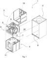
- Figure 1 shows an air supply device 1 having components ready to be assembled together.
- the air supply unit comprises a casing 2 further comprising a separate bottom sheet 8.
- the air supply device 1 comprises a body which comprises two parts, an upper part 3 and a lower part 4 where the body and thus both of the upper part 3 and the lower part 4 are made of elastic material.
- the body further comprises an exhaust air channel 5 and a supply air channel 6.
- the exhaust air channel 5 is arranged to receive exhaust air from a room into the air supply device and conduct the exhaust air out of the air supply device and further out of the building, and the supply air channel is arranged to receive fresh supply air into the air supply device and conduct the supply air further out of the air supply device into the room.
- the exhaust air channel 5 and the supply air channel 6 run inside the air supply device 1 in parallel and forms a shape of U so that the each exhaust air channel 5 and the supply air channel 6 comprise two vertical portions and a horizontal portion between the vertical portions.
- the exhaust air and the supply air inside the respective channels flow in opposite directions.
- the upper part 3 comprises a frame 10 and an internal part 9, which internal part 9 is arranged to be installed inside the frame 10.
- the internal part 9 is in first position and ready to be installed inside the frame 10. However, it is possible to rotate the internal part 9 180° in horizontal plane before installing it inside the frame 10. This rotated position is a second position in which the internal part is possible to be installed inside the frame 10.
- the lower part 4 comprises a heat transfer unit 7 as illustrated in figure 1 .
- the heat transfer unit 7 comprises a rotating heat transfer element 11.
- the rotating heat transfer element 11 is arranged to rotate in vertical position around a horizontal axis, and to transfer thermal energy from one air flow into the other.
- the rotating heat transfer element 11 is arranged to rotate in horizontal position around a vertical axis and to transfer thermal energy from one air flow into the other.
- the heat transfer unit 7 is arranged within the horizontal portions of the exhaust air channel 5 and the supply air channel 6.
- the upper part 3 (with all the components inside) is installed on top of the lower part 4. Thereafter the body with the upper and lower part on top of each other is installed inside the casing 2 e.g. by sliding the body into the casing 2 through a front door opening of the casing 2. Alternatively the lower part 4 is slid into the casing 2 first and the upper part 3 is thereafter carefully slid onto the lower part 4.
- the inner part 9 is made of the same elastic material as the body.
- the inner part 9 forms the exhaust air channel 5 and the supply air channel 6 inside the upper part.
- the frame 10 is made of the same elastic material as the body.
- the inner part 9 comprises vertical sealing surfaces 22 which seal the inner part 9 against side walls of the upper part 3.
- the vertical sealing surfaces 22 may comprise seals e.g. weather stripes.
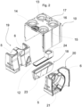
- FIG. 2 shows an exploded view of the upper part 3 of the air supply device 1 according to one embodiment.
- the exhaust air channel 5 comprises an exhaust air inlet 14 and an exhaust air outlet 15, and the supply air channel 6 comprises a supply air inlet 16 and a supply air outlet 13.
- the internal part 9 comprises a first half 19 and a second half 20 which are arranged side by side in horizontal plane.
- the first half 19 and the second half 20 may be connected together by squeezing them against each other or they may be connected by using glue or some adhesive compound.
- the supply air outlet 13 and the exhaust air inlet 14 are located in the first half 19, and the supply air inlet 16 and the exhaust air outlet 15 are located second half 20. If the internal part 9 is rotated 180° in horizontal plane, the position of the inlets and outlets changes as illustrated in figures 3 and 4 later.
- the exhaust air channel 5 and the supply air channel 6 may have larger chambers near the outlets or inlets. These chambers may comprise an air fan or fans for accelerating the air flows inside the air channels. It is possible that only one air channel exhaust air channel 5 or the supply air channel 6 comprise said air fan.
- the internal part 9 comprises a cooker hood air channel 18 arranged inside the frame 10. Buildings may have a separate cooker hood air duct for removing cooker hood air out of the rooms and further out of the building.
- the cooker hood air channel 18 is a separate component which may be installed to the air supply device 1.
- the cooker hood air channel 18 comprises a cooker hood air opening 24.
- the cooker hood air opening 24 is connected to the cooker hood air inlet 17, which is further connected to the cooker hood air duct of the building.
- the cooker hood air is extracted from the building into the air supply device 1 through the cooker hood air inlet 17.
- the cooker hood air channel 18 is arranged between the first half 19 and the second half 20.
- the cooker hood air channel 18 may be connected to the first half 19 and the second half 20 by squeezing it between the first half 19 and the second half 20 or it may be glued or connected by some adhesive compound.
- the cooker hood channel 18 is connected to the exhaust air channel 5.
- the cooker hood channel 18 comprises an opening 23, through which the cooker hood air is conducted from the cooker hood air channel 18 into the exhaust air channel 5, which comprises another opening in the corresponding location.
- the extracted cooker hood air is further conducted into the exhaust air channel 5 and further outside of the building.
- the cooker hood air channel 18 comprises removable lid 12 having a cooker hood air opening 24 connected to the cooker hood air inlet 17.
- the cooker hood air opening 24 is arranged at one end of the removable lid 12.
- the removable lid 12 comprises electrical components which are used to operate the air supply device 1.
- the electrical components are arranged on top of the removable lid and at the opposite end than the cooker hood air opening 24.
- the removable lid 12 is arranged to be installed in the same position regardless the position of the internal part 9. Therefore, the electrical components and the cooker hood air opening 24 are always in the same location inside the air supply device 1.
- the cooker hood air inlet 17 in the first position is between the supply air inlet 16 and the supply air outlet 13, and in the second position the cooker hood air inlet 17 is between the exhaust air inlet 14 and the exhaust air outlet 15.
- the air supply device comprises at least one heat exchanger 21 arranged inside the exhaust air channel 5 or the supply air channel 6.
- the heat exchanger may be used for heating or cooling the air flow inside the air channel.
- the air supply device comprises heat exchangers 21 arranged inside the exhaust air channel 5 and the supply air channel 6.
- the elastic material is expanded polypropylene (EPP).
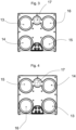
- Figure 3 shows a detailed view of the air supply device 1 from above wherein the internal part 9 is installed in a first position.
- the supply air inlet 16 is located in the top right corner and the supply air outlet 13 is located in the top left corner.
- the exhaust air inlet 14 is located in the bottom left corner and the exhaust air outlet 15 is located in the bottom right corner.
- the supply air inlet 16 and the supply air outlet 13 may change places, and at the same time, the exhaust air inlet 14 and the exhaust air outlet 15 change places also.
- Figure 4 shows a detailed view of the air supply device from above wherein the internal part is installed in a second position.
- the supply air inlet 16 is located in the bottom left corner and the supply air outlet 13 is located in the bottom right corner.
- the exhaust air inlet 14 is located in the top right corner and the exhaust air outlet 15 is located in the top left corner.
- the supply air inlet 16 and the supply air outlet 13 may change places, and at the same time, the exhaust air inlet 14 and the exhaust air outlet 15 change places also.
- the cooker hood air inlet 17 is always located in the same place. However, it is possible that the air supply device 1 does not comprise the cooker hood air inlet 17 at all.
Landscapes
- Engineering & Computer Science (AREA)
- Chemical & Material Sciences (AREA)
- Combustion & Propulsion (AREA)
- Mechanical Engineering (AREA)
- General Engineering & Computer Science (AREA)
- Ventilation (AREA)
Claims (15)
- Luftversorgungsgerät (1) zum Extrahieren von Abluft aus einem Raum und zum Leiten von frischer Zuluft in den Raum, umfassend- ein Gehäuse (2), das eine äußere Schicht des Luftversorgungsgeräts (1) bildet, und- einen Körper aus elastischem Material, der innerhalb des Gehäuses (2) eingerichtet ist, wobei- der Körper in mindestens einen oberen Teil (3) und einen unteren Teil (4) geteilt ist, die aufeinander eingerichtet sind,- der obere Teil (3) einen inneren Teil (9) und einen Rahmen (10) umfasst, wobei der innere Teil (9) innerhalb des Rahmens (10) eingerichtet ist, und- der innere Teil (9) dazu eingerichtet ist, innerhalb des Rahmens (10) in einer ersten Position oder in einer zweiten Position installiert zu werden, wobei in der zweiten Position der innere Teil (9) um 180° in einer horizontalen Ebene im Vergleich zu der ersten Position rotiert worden ist, der innere Teil (9) einen Dunstabzugshauben-Luftkanal (18) umfasst, der innerhalb des Rahmens (10) eingerichtet ist.
- Luftversorgungsgerät gemäß Anspruch 1,
dadurch gekennzeichnet, dass das Luftversorgungsgerät (1) einen Abluftkanal (5) und einen Zuluftkanal (6) umfasst, die innerhalb des Gehäuses eingerichtet sind. - Luftversorgungsgerät gemäß Anspruch 2,
dadurch gekennzeichnet, dass der Rahmen (10) Folgendes umfasst- einen Ablufteinlass (14) und einen Abluftauslass (15), die mit dem Abluftkanal (5) verbunden sind, und- einen Zulufteinlass (16) und einen Zuluftauslass (13), die mit dem Zuluftkanal (6) verbunden sind. - Luftversorgungsgerät gemäß Anspruch 3,
dadurch gekennzeichnet, dass der innere Teil (9) eine erste Hälfte (19) und eine zweite Hälfte (20) umfasst, die Seite an Seite in einer horizontalen Ebene eingerichtet sind, wobei die erste Hälfte (19) mit dem Zuluftauslass (13) und dem Ablufteinlass (14) verbunden ist, und die zweite Hälfte (20) mit dem Zulufteinlass (16) und dem Abluftauslass (15) verbunden ist. - Luftversorgungsgerät gemäß einem der Ansprüche 1 bis 4,
dadurch gekennzeichnet, dass der Rahmen 10 einen Dunstabzugshauben-Lufteinlass (17) umfasst, der mit dem Dunstabzugshauben-Luftkanal (18) verbunden ist. - Luftversorgungsgerät gemäß Anspruch 4 oder Anspruch 5, wenn abhängig von Anspruch 4,
dadurch gekennzeichnet, dass der Dunstabzugshauben-Luftkanal (18) zwischen der ersten Hälfte (19) und der zweiten Hälfte (20) eingerichtet ist. - Luftversorgungsgerät gemäß einem der Ansprüche 2 bis 6,
dadurch gekennzeichnet, dass der Dunstabzugshauben-Luftkanal (18) mit dem Abluftkanal (5) verbunden ist. - Luftversorgungsgerät gemäß einem der Ansprüche 1 bis 7,
dadurch gekennzeichnet, dass der Dunstabzugshauben-Luftkanal (18) einen abnehmbaren Deckel (12) mit einer Dunstabzugshauben-Luftkanalöffnung (24) umfasst. - Luftversorgungsgerät gemäß Anspruch 8,
dadurch gekennzeichnet, dass der abnehmbare Deckel (12) dazu eingerichtet ist, in derselben Position installiert zu werden, ungeachtet der Position des inneren Teils (9). - Luftversorgungsgerät gemäß Anspruch 9,
dadurch gekennzeichnet, dass sich in der ersten Position der Dunstabzugshauben-Lufteinlass (17) zwischen dem Zulufteinlass (16) und dem Zuluftauslass (13) befindet und sich in der zweiten Position der Dunstabzugshauben-Lufteinlass (17) zwischen dem Ablufteinlass (14) und dem Abluftauslass (15) befindet. - Luftversorgungsgerät gemäß einem der Ansprüche 2 bis 10,
dadurch gekennzeichnet, dass das Luftversorgungsgerät mindestens einen Wärmetauscher (21) umfasst, der innerhalb des Abluftkanals (5) oder des Zuluftkanals (6) eingerichtet ist. - Luftversorgungsgerät gemäß einem der Ansprüche 2 bis 10,
dadurch gekennzeichnet, dass das Luftversorgungsgerät Wärmetauscher (21) umfasst, die innerhalb des Abluftkanals (5) und des Zuluftkanals (6) eingerichtet sind. - Luftversorgungsgerät gemäß einem der vorangehenden Ansprüche,
dadurch gekennzeichnet, dass das elastische Material expandiertes Polypropylen (EPP) ist. - Luftversorgungsgerät gemäß einem der vorangehenden Ansprüche,
dadurch gekennzeichnet, dass eine Wärmeübertragungseinheit (7) innerhalb des unteren Teils (4) des Körpers eingerichtet ist, und in dem Abluftkanal (5) und dem Zuluftkanal (6), um Wärmeenergie zwischen Abluft, die in dem Abluftkanal (5) strömt, und Zuluft, die in dem Zuluftkanal strömt, zu übertragen. - Luftversorgungsgerät gemäß Anspruch 14,
dadurch gekennzeichnet, dass die Wärmeübertragungseinheit (7) ein rotierendes Wärmeübertragungselement (11) umfasst.
Priority Applications (2)
| Application Number | Priority Date | Filing Date | Title |
|---|---|---|---|
| PL17189048.6T PL3450873T3 (pl) | 2017-09-01 | 2017-09-01 | Urządzenie doprowadzające powietrze |
| EP17189048.6A EP3450873B1 (de) | 2017-09-01 | 2017-09-01 | Luftzufuhrvorrichtung |
Applications Claiming Priority (1)
| Application Number | Priority Date | Filing Date | Title |
|---|---|---|---|
| EP17189048.6A EP3450873B1 (de) | 2017-09-01 | 2017-09-01 | Luftzufuhrvorrichtung |
Publications (3)
| Publication Number | Publication Date |
|---|---|
| EP3450873A1 EP3450873A1 (de) | 2019-03-06 |
| EP3450873B1 true EP3450873B1 (de) | 2024-12-25 |
| EP3450873C0 EP3450873C0 (de) | 2024-12-25 |
Family
ID=59772468
Family Applications (1)
| Application Number | Title | Priority Date | Filing Date |
|---|---|---|---|
| EP17189048.6A Active EP3450873B1 (de) | 2017-09-01 | 2017-09-01 | Luftzufuhrvorrichtung |
Country Status (2)
| Country | Link |
|---|---|
| EP (1) | EP3450873B1 (de) |
| PL (1) | PL3450873T3 (de) |
Family Cites Families (5)
| Publication number | Priority date | Publication date | Assignee | Title |
|---|---|---|---|---|
| FR2533682A1 (fr) * | 1982-09-24 | 1984-03-30 | Fimec | Perfectionnements aux echangeurs de temperature a flux croises, notamment pour systemes de ventilation mecanique pour locaux |
| NO20034036L (no) * | 2003-09-12 | 2005-03-14 | Systemair As | Ventilasjonsaggregat kombinert med varmegjenvinner og separat tilkopling til kjokkenavtrekk |
| WO2008018361A1 (fr) * | 2006-08-11 | 2008-02-14 | Daikin Industries, Ltd. | Mécanisme de ventilation |
| GB0803674D0 (en) * | 2008-02-28 | 2008-04-09 | Hendrickson Thor | Ventilation system |
| KR101640411B1 (ko) * | 2009-10-16 | 2016-07-18 | 엘지전자 주식회사 | 공기조화기 |
-
2017
- 2017-09-01 PL PL17189048.6T patent/PL3450873T3/pl unknown
- 2017-09-01 EP EP17189048.6A patent/EP3450873B1/de active Active
Also Published As
| Publication number | Publication date |
|---|---|
| PL3450873T3 (pl) | 2025-04-22 |
| EP3450873A1 (de) | 2019-03-06 |
| EP3450873C0 (de) | 2024-12-25 |
Similar Documents
| Publication | Publication Date | Title |
|---|---|---|
| US9845959B2 (en) | Ventilation device for ventilation of rooms in buildings | |
| HRP20170829T1 (hr) | Četvrtastog oblika, posebno kubičnog, kućište za održavanje komponenti klime i/ili sustava kontrole sobnog zraka | |
| US11209104B2 (en) | Fastening system for a pipe passing through a panel of an air handling unit, and air handling unit comprising such a system | |
| US20140196495A1 (en) | Adaptable hvac unit base | |
| EP2700884A1 (de) | Wärmespeicherstrahlung-Klimaanlage mit Wärmepumpenklimaanlage | |
| CN107036223A (zh) | 多功能室内新风空调设备 | |
| CN107429940B (zh) | 用于空气处理单元的面板、用于组装这种面板的方法以及包括这种面板的空气处理单元 | |
| EP2754972B1 (de) | Belüftungsvorrichtung für Gebäude mit einem Ventil zum Öffnen und Verschließen einer Öffnung für den Durchgang einer Luftströmung | |
| EP3450873B1 (de) | Luftzufuhrvorrichtung | |
| US20080311839A1 (en) | Heat exchanging ventilator | |
| CN206055765U (zh) | 空调机的室内机 | |
| CN107208923A (zh) | 推挽式逆流热交换器 | |
| CN210889276U (zh) | 气缸、空气输送装置和空调系统 | |
| CN104499736A (zh) | 一种恒温控制实验室 | |
| JP2016223679A (ja) | ダクト型空気調和機 | |
| EP3450863B1 (de) | Luftzufuhrvorrichtung | |
| CN106574780A (zh) | 管道换气装置 | |
| US10101040B2 (en) | Packaged terminal air conditioner unit | |
| EP2439353A2 (de) | Wärmeerfassungssystem | |
| EP3450872B1 (de) | Luftzufuhrvorrichtung | |
| US20150013251A1 (en) | Methods and apparatus for accessing hvac coil | |
| CN106931580B (zh) | 一种管道式换气装置 | |
| KR101742532B1 (ko) | 열회수용 환기장치 | |
| CN104236135A (zh) | 开口位置能变更的处理单元 | |
| GB2536428A (en) | Building ventilator |
Legal Events
| Date | Code | Title | Description |
|---|---|---|---|
| PUAI | Public reference made under article 153(3) epc to a published international application that has entered the european phase |
Free format text: ORIGINAL CODE: 0009012 |
|
| STAA | Information on the status of an ep patent application or granted ep patent |
Free format text: STATUS: THE APPLICATION HAS BEEN PUBLISHED |
|
| AK | Designated contracting states |
Kind code of ref document: A1 Designated state(s): AL AT BE BG CH CY CZ DE DK EE ES FI FR GB GR HR HU IE IS IT LI LT LU LV MC MK MT NL NO PL PT RO RS SE SI SK SM TR |
|
| AX | Request for extension of the european patent |
Extension state: BA ME |
|
| STAA | Information on the status of an ep patent application or granted ep patent |
Free format text: STATUS: REQUEST FOR EXAMINATION WAS MADE |
|
| 17P | Request for examination filed |
Effective date: 20190903 |
|
| RBV | Designated contracting states (corrected) |
Designated state(s): AL AT BE BG CH CY CZ DE DK EE ES FI FR GB GR HR HU IE IS IT LI LT LU LV MC MK MT NL NO PL PT RO RS SE SI SK SM TR |
|
| STAA | Information on the status of an ep patent application or granted ep patent |
Free format text: STATUS: EXAMINATION IS IN PROGRESS |
|
| 17Q | First examination report despatched |
Effective date: 20200724 |
|
| GRAP | Despatch of communication of intention to grant a patent |
Free format text: ORIGINAL CODE: EPIDOSNIGR1 |
|
| STAA | Information on the status of an ep patent application or granted ep patent |
Free format text: STATUS: GRANT OF PATENT IS INTENDED |
|
| RIC1 | Information provided on ipc code assigned before grant |
Ipc: F24F 12/00 20060101ALN20240710BHEP Ipc: F24F 13/20 20060101AFI20240710BHEP |
|
| INTG | Intention to grant announced |
Effective date: 20240723 |
|
| GRAS | Grant fee paid |
Free format text: ORIGINAL CODE: EPIDOSNIGR3 |
|
| GRAA | (expected) grant |
Free format text: ORIGINAL CODE: 0009210 |
|
| STAA | Information on the status of an ep patent application or granted ep patent |
Free format text: STATUS: THE PATENT HAS BEEN GRANTED |
|
| AK | Designated contracting states |
Kind code of ref document: B1 Designated state(s): AL AT BE BG CH CY CZ DE DK EE ES FI FR GB GR HR HU IE IS IT LI LT LU LV MC MK MT NL NO PL PT RO RS SE SI SK SM TR |
|
| REG | Reference to a national code |
Ref country code: GB Ref legal event code: FG4D |
|
| REG | Reference to a national code |
Ref country code: CH Ref legal event code: EP |
|
| REG | Reference to a national code |
Ref country code: DE Ref legal event code: R096 Ref document number: 602017086925 Country of ref document: DE |
|
| REG | Reference to a national code |
Ref country code: IE Ref legal event code: FG4D |
|
| U01 | Request for unitary effect filed |
Effective date: 20250122 |
|
| U07 | Unitary effect registered |
Designated state(s): AT BE BG DE DK EE FI FR IT LT LU LV MT NL PT RO SE SI Effective date: 20250128 |
|
| PG25 | Lapsed in a contracting state [announced via postgrant information from national office to epo] |
Ref country code: HR Free format text: LAPSE BECAUSE OF FAILURE TO SUBMIT A TRANSLATION OF THE DESCRIPTION OR TO PAY THE FEE WITHIN THE PRESCRIBED TIME-LIMIT Effective date: 20241225 |
|
| PG25 | Lapsed in a contracting state [announced via postgrant information from national office to epo] |
Ref country code: GR Free format text: LAPSE BECAUSE OF FAILURE TO SUBMIT A TRANSLATION OF THE DESCRIPTION OR TO PAY THE FEE WITHIN THE PRESCRIBED TIME-LIMIT Effective date: 20250326 |
|
| PG25 | Lapsed in a contracting state [announced via postgrant information from national office to epo] |
Ref country code: RS Free format text: LAPSE BECAUSE OF FAILURE TO SUBMIT A TRANSLATION OF THE DESCRIPTION OR TO PAY THE FEE WITHIN THE PRESCRIBED TIME-LIMIT Effective date: 20250325 |
|
| PG25 | Lapsed in a contracting state [announced via postgrant information from national office to epo] |
Ref country code: SM Free format text: LAPSE BECAUSE OF FAILURE TO SUBMIT A TRANSLATION OF THE DESCRIPTION OR TO PAY THE FEE WITHIN THE PRESCRIBED TIME-LIMIT Effective date: 20241225 |
|
| PG25 | Lapsed in a contracting state [announced via postgrant information from national office to epo] |
Ref country code: ES Free format text: LAPSE BECAUSE OF FAILURE TO SUBMIT A TRANSLATION OF THE DESCRIPTION OR TO PAY THE FEE WITHIN THE PRESCRIBED TIME-LIMIT Effective date: 20241225 |
|
| PG25 | Lapsed in a contracting state [announced via postgrant information from national office to epo] |
Ref country code: IS Free format text: LAPSE BECAUSE OF FAILURE TO SUBMIT A TRANSLATION OF THE DESCRIPTION OR TO PAY THE FEE WITHIN THE PRESCRIBED TIME-LIMIT Effective date: 20250425 |
|
| PG25 | Lapsed in a contracting state [announced via postgrant information from national office to epo] |
Ref country code: SK Free format text: LAPSE BECAUSE OF FAILURE TO SUBMIT A TRANSLATION OF THE DESCRIPTION OR TO PAY THE FEE WITHIN THE PRESCRIBED TIME-LIMIT Effective date: 20241225 |
|
| PG25 | Lapsed in a contracting state [announced via postgrant information from national office to epo] |
Ref country code: CZ Free format text: LAPSE BECAUSE OF FAILURE TO SUBMIT A TRANSLATION OF THE DESCRIPTION OR TO PAY THE FEE WITHIN THE PRESCRIBED TIME-LIMIT Effective date: 20241225 |
|
| REG | Reference to a national code |
Ref country code: CH Ref legal event code: U11 Free format text: ST27 STATUS EVENT CODE: U-0-0-U10-U11 (AS PROVIDED BY THE NATIONAL OFFICE) Effective date: 20251001 |
|
| PGFP | Annual fee paid to national office [announced via postgrant information from national office to epo] |
Ref country code: NO Payment date: 20250923 Year of fee payment: 9 |
|
| PGFP | Annual fee paid to national office [announced via postgrant information from national office to epo] |
Ref country code: PL Payment date: 20250821 Year of fee payment: 9 |
|
| U20 | Renewal fee for the european patent with unitary effect paid |
Year of fee payment: 9 Effective date: 20250924 |
|
| PLBE | No opposition filed within time limit |
Free format text: ORIGINAL CODE: 0009261 |
|
| STAA | Information on the status of an ep patent application or granted ep patent |
Free format text: STATUS: NO OPPOSITION FILED WITHIN TIME LIMIT |
|
| 26N | No opposition filed |
Effective date: 20250926 |