EP3450871B1 - Luftzufuhrvorrichtung - Google Patents
Luftzufuhrvorrichtung Download PDFInfo
- Publication number
- EP3450871B1 EP3450871B1 EP17189042.9A EP17189042A EP3450871B1 EP 3450871 B1 EP3450871 B1 EP 3450871B1 EP 17189042 A EP17189042 A EP 17189042A EP 3450871 B1 EP3450871 B1 EP 3450871B1
- Authority
- EP
- European Patent Office
- Prior art keywords
- air
- supply device
- air channel
- air supply
- exhaust air
- Prior art date
- Legal status (The legal status is an assumption and is not a legal conclusion. Google has not performed a legal analysis and makes no representation as to the accuracy of the status listed.)
- Active
Links
Images


Classifications
-
- F—MECHANICAL ENGINEERING; LIGHTING; HEATING; WEAPONS; BLASTING
- F24—HEATING; RANGES; VENTILATING
- F24F—AIR-CONDITIONING; AIR-HUMIDIFICATION; VENTILATION; USE OF AIR CURRENTS FOR SCREENING
- F24F13/00—Details common to, or for air-conditioning, air-humidification, ventilation or use of air currents for screening
- F24F13/20—Casings or covers
-
- F—MECHANICAL ENGINEERING; LIGHTING; HEATING; WEAPONS; BLASTING
- F24—HEATING; RANGES; VENTILATING
- F24F—AIR-CONDITIONING; AIR-HUMIDIFICATION; VENTILATION; USE OF AIR CURRENTS FOR SCREENING
- F24F12/00—Use of energy recovery systems in air conditioning, ventilation or screening
- F24F12/001—Use of energy recovery systems in air conditioning, ventilation or screening with heat-exchange between supplied and exhausted air
-
- F—MECHANICAL ENGINEERING; LIGHTING; HEATING; WEAPONS; BLASTING
- F24—HEATING; RANGES; VENTILATING
- F24F—AIR-CONDITIONING; AIR-HUMIDIFICATION; VENTILATION; USE OF AIR CURRENTS FOR SCREENING
- F24F2203/00—Devices or apparatus used for air treatment
- F24F2203/10—Rotary wheel
- F24F2203/104—Heat exchanger wheel
-
- Y—GENERAL TAGGING OF NEW TECHNOLOGICAL DEVELOPMENTS; GENERAL TAGGING OF CROSS-SECTIONAL TECHNOLOGIES SPANNING OVER SEVERAL SECTIONS OF THE IPC; TECHNICAL SUBJECTS COVERED BY FORMER USPC CROSS-REFERENCE ART COLLECTIONS [XRACs] AND DIGESTS
- Y02—TECHNOLOGIES OR APPLICATIONS FOR MITIGATION OR ADAPTATION AGAINST CLIMATE CHANGE
- Y02B—CLIMATE CHANGE MITIGATION TECHNOLOGIES RELATED TO BUILDINGS, e.g. HOUSING, HOUSE APPLIANCES OR RELATED END-USER APPLICATIONS
- Y02B30/00—Energy efficient heating, ventilation or air conditioning [HVAC]
- Y02B30/56—Heat recovery units
Definitions
- the present invention relates to an air supply device for extracting exhaust air from a room and leading fresh air into the room.
- Objective of the present invention is to provide an air supply device which is possible to dismantle without damaging any parts of it.
- an air supply device according to claim 1 is provided.
- the upper part and the lower part are arranged to be squeezed against each other in vertical direction when the bottom sheet is lifted.
- the casing may be made of for example metal, plastic or wood so that it protects internal parts of the device.
- the adjusting means for adjusting the vertical position of the bottom sheet may comprise a screw or screws which are tightened underneath the air supply device. Some of the tightening screws may be located at the back portion of the bottom sheet. Therefore, there may be difficulties to adjust these screws when the air supply device is installed inside a cabin or between cabins in a building. However, the screw(s) at the back portion of the bottom sheet may comprise an extra lever which extends from underneath the air supply device to the front side of the air supply device.
- the lower part and the upper part are squeezed together and against the casing.
- Contacting surfaces between the lower part and the upper part are pushed together and contacting surfaces are deformed and, therefore, sealing the body more air tight.
- only the contacting surfaces of the upper part or the lower part are deformed.
- a sufficient deformation of the contacting surfaces is a squeeze of 0,1-3 mm of the elastic material at the contacting surfaces.
- the contacting surfaces between the body and the casing may be sealed together by regular seals (e.g. weather strip).
- the upper part of the body is a wedge shape so that the upper part narrows upwards.
- the narrowing upper part is squeezed more together when the bottom sheet is lifted upwards.
- the upper part is narrowed upwards so that the angle ⁇ between side walls of the upper part is 10° or less.
- the upper part is narrowed upwards so that the angle ⁇ between side walls of the upper part is 5° or less.
- the upper part is narrowed upwards so that the angle ⁇ between side walls of the upper part is 2° or less.
- contacting surfaces between the upper part and the lower part comprises a tongue and groove joint.
- the tongue and the groove may be positioned on either of the upper part or the lower part but not so that both are positioned on the same part.
- the other one of the upper part and the lower part comprises a tongue at the contacting surface and the other one has a flat contacting surface.
- the tongue may have a shape of triangle, square, rectangle, trapezoid etc.
- the shape of the tongue narrows while extending outward from the upper part of lower part.
- the groove on the opposite contacting surface opposite the tongue has corresponding shape in order to make a good contact, e.g. a triangular groove with a wide opening and a narrow end so as to fit a triangular tongue within the groove.
- a heat transfer unit is arranged inside the lower part of the body and within the exhaust air channel and the supply air channel to transfer thermal energy between exhaust air flowing in the exhaust air channel, and supply air flowing in the supply air channel.
- the heat transfer unit may be fixed or replaced by removing the lower part only from the air supply device.
- the heat transfer unit may be installed inside the lower part before the lower part is brought to the installation plant.
- the upper part comprises the air supply channel and a supply air fan inside the supply air channel for boosting the flow of the supply air into the room.
- the supply air fan in the upper part of the body and above the heat transfer unit, the casing of the air supply device may have smaller surface area.
- the upper part of the body comprises the exhaust air channel and an exhaust air fan inside the exhaust air channel for boosting the flow of the exhaust air from the room.
- the casing of the air supply device may have smaller surface area.
- the upper part of the body comprises an exhaust air inlet and an exhaust air outlet, and a supply air inlet and a supply air outlet.
- the inlets and outlets are used to connect exhaust air and supply air ducts to the air supply device.
- Each of said inlets and outlets are made of the elastic material.
- the upper part of the body comprises a cooker hood air channel connected to the exhaust air channel and having a closed cooker hood air inlet.
- the cooker hood air channel and the closed cooker hood air inlet are made of the elastic material.
- Air supply devices according to this embodiment are intended to be installed inside buildings which may have a separate cooker hood duct for extracting cooker hood exhaust air from the building. By default, the cooker hood inlet of the cooker hood air channel is closed. However, there is an option to cut it open if the building comprises a cooker hood duct which is to be connected to the air supply device for extracting the cooker hood air from the building.
- the cooker hood air inlet for the cooker hood air channel is a continuous part of the body of the upper part.
- the elastic material is expanded polypropylene (EPP).
- EPP has good thermal insulation properties and its elasticity is suitable for squeezing parts made of EPP together. It is also light material and, therefore, the weight of the body parts is lower than in air supply devices with metal parts.
- the elastic material of the body may also be expanded polystyrene (EPS) but EPP is more elastic and less brittle.
- EPS expanded polystyrene
- the heat transfer unit comprises a rotating heat transfer element.
- the rotating heat transfer element rotates around horizontal axis.
- the lower part of the body comprises at least one air filter inside an air channel.
- the air filter may be inside the exhaust air channel or it may be inside the supply air channel.
- An alternative is also to have separate air filters inside both of these air channels.
- the lower part and the upper part are detachably squeezed against each other, wherein the lower part of the body is configured to loosen from the upper part of the body. Because the upper part and the lower part of the body are not fastened to each other by any fastening compound such as a sealing compound or glue, it is possible to detach these body parts from each other without causing any damages to the parts and/or their contacting surfaces.
- any fastening compound such as a sealing compound or glue
- the lower part of the body is configured to loosen from the upper part of the body when the bottom sheet is lowered.
- the lower part and the upper part are pre-assembled modules.
- the upper part and the lower part may comprise different parts arranged inside the body.
- Inside the lower part there is a heat exchanger unit and also there may be air filter or filters for cleaning the air that flows inside the device and through such filter of filters.
- the upper part and the lower part may be pre-assembled for example in a factory when manufacturing the air supply device in order to avoid having to assemble these parts when installing the air supply device in the building where it will be used. This way the person installing the air supply device only needs to install the upper part and the lower part into the casing of the air supply device and to connect the air supply device to a power supply.
- the casing has the shape of a rectangular solid that has a rectangular front door via which the upper part and the lower part may be inserted and removed by sliding the upper part and/or lower part horizontally transversely to a front opening when the front door is open.
- the upper part and the lower part are configured to be squeezed against each other with sufficient pressure to achieve a tightness in contact surfaces of the upper part and lower part so that the leakage air flow per surface area of the device in the contact surfaces is 0,27 x p s 0,65 or lower, wherein p s is a test pressure.
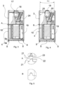
- Figure 1 shows an air supply device 1 having components ready to be assembled together.
- the air supply unit comprises a casing 2 further comprising a separate bottom sheet 8.
- the air supply device 1 comprises a body which comprises two parts, an upper part 3 and a lower part 4 where the body and thus both of the upper part 3 and the lower part 4 are made of elastic material.
- the body further comprises an exhaust air channel 5 and a supply air channel 6.
- the exhaust air channel 5 is arranged to receive exhaust air from a room into the air supply device and conduct the exhaust air out of the air supply device and further out of the building, and the supply air channel is arranged to receive fresh supply air into the air supply device and conduct the supply air further out of the air supply device into the room.
- the exhaust air channel 5 and the supply air channel 6 run inside the air supply device 1 in parallel and forms a shape of U so that the each exhaust air channel 5 and the supply air channel 6 comprise two vertical portions and a horizontal portion between the vertical portions.
- the exhaust air and the supply air inside the respective channels flow in opposite directions.
- the air supply device comprises a heat transfer unit 7 within the exhaust air channel 5 and the supply air channel 6, which heat transfer unit 7 transfers thermal energy between the exhaust air and the supply air before the exhaust air is blown out of the building and the supply air into the room.
- the heat transfer unit comprises a rotating heat transfer element 11.
- the rotating heat transfer element 11 is arranged to rotate in vertical position around a horizontal axis and to transfer thermal energy from one air flow into the other.
- the rotating heat transfer element 11 is arranged to rotate in horizontal position around a vertical axis and to transfer thermal energy from one air flow into the other.
- the heat transfer unit 7 is arranged within the horizontal portions of the exhaust air channel 5 and the supply air channel 6.
- the heat transfer unit 7 comprises vertical dividing elements 10 to separate the exhaust air channel 5 and the supply air channel 6 from each other.
- the heat transfer unit 7 comprises horizontal dividing elements to divide the exhaust air channel 5 and the supply air channel 6 from each other.
- the dividing elements 10 are removable elements, which may be removed and installed again.
- the casing 2 is made of metal, plastic or wood.
- the upper part 3 (with all the components inside) is installed on top of the lower part 4. Thereafter the body with the upper and lower part on top of each other is installed inside the casing 2 e.g. by sliding the body into the casing 2 through a front door opening of the casing 2. Alternatively the lower part 4 is slid into the casing 2 first and the upper part 3 is thereafter carefully slid onto the lower part 4.
- the upper part 3 comprises a separate inner part 25, which is made of the same elastic material as the body.
- the inner part 25 forms the exhaust air channel 5 and the supply air channel 6 inside the upper part.
- the inner part 25 comprises vertical sealing surfaces 26 which seal the inner part 25 against side walls of the upper part 3.
- the vertical sealing surfaces 26 may comprise seals e.g. weather stripes.
- the heat transfer unit comprises the rotating heat transfer element 11.
- the lower part 4 comprises dividing elements 10, which separate the exhaust air channel and the supply air channel inside the lower part 4 so that the supply air flow and the exhaust air flow do not mix.
- Figure 2 shows an air supply device 1 seen from outside its casing 2.
- the casing 2 comprises a wall 25 comprising a hatch or front door 12, which may be opened for maintenance.
- the upper end of the air supply device 1 comprises a supply air outlet 13, an exhaust air inlet 14, an exhaust air outlet 15 and a supply air inlet 16.
- the order of the inlets and outlets may differ in some embodiments.
- the supply air inlet 16 and outlet 13 may be closer to the wall 25 comprising the front door 12, and the exhaust air inlet 14 and outlet 15 may be farther from the wall comprising the front door 12.
- the air supply device 1 comprises a cooker hood air inlet 17 for cooker hood exhaust air.
- the cooker hood air inlet 17, in figure 2 is made of same material as the body.
- the cooker hood air inlet 17 is closed with a cap 17a that is integral with the body when manufacturing the body.
- the cooker hood air inlet 17 may be opened at the installation site if the building comprises a duct for cooker hood exhaust air and the air supply device 1 is to be connected to it. This may be done by sawing the cap 17a with a saw or cutting the cap 17a with a knife.
- the elastic material such as EPP, can easily be cut or sawed and thus removing the cap 17a can be done rather quickly.
- Figures 3 and 4 show a cross sectional front view of the air supply device.
- the bottom sheet 8 is in its lowest position and the lower part 4 and the upper part 3 are in a resting position, wherein no pressure is yet affected on them.
- the lower part 4 and the upper part 5 may even have a little gap between them, as seen in figure 3 .
- the bottom sheet 8 is lifted and the lower part 4 and the upper part 3 of the body are squeezed together, and against the casing to bring them into an installed position. In the installed position, it is possible to keep leakage air level out of the device lower.
- the upper part 3 and the lower part 4 are arranged to be squeezed against each other in vertical direction when the bottom sheet 8 is lifted.
- the upper part 3 and the lower part 4 are configured to be squeezed against each other with sufficient pressure to achieve a tightness in contact surfaces of the upper part and lower part so that the leakage air flow per surface area of the device in the contact surfaces is 0,27 x p s 0,65 or lower, wherein p s is a test pressure.
- Figures 3 and 4 show also a cooker hood exhaust air channel 18, arranged inside the upper part 3, which connects the cooker hood air inlet 17 to the exhaust air channel 5.
- the lower part 4 comprises an air filter 19 for removing impurities or some unwanted particles from the flowing air.
- the air filter 19 is located inside the exhaust air channel 5 or the supply air channel 6.
- both of the exhaust air channel and the supply air channel have an air filter 19 inside.
- the adjusting means 9 for adjusting the vertical position of the bottom sheet 8 are seen in at the bottom of the air supply device 1.
- the adjusting means 9 are illustrated by a bolt 9a and nut 9b but may as well be screws with nuts 9b, or instead of nuts corresponding internal threads in the casing 2, which are tightened (see figure 4 ) for lifting the bottom sheet 8, and untightened (see figure 3 ) for lowering the bottom sheet 8.
- the bottom sheet comprises tightening screws, as adjusting means 9, on every corner of the square or rectangular shaped bottom sheet 8.
- the adjusting means 9 may, however, comprise extra lever or levers connected to these screws, located at the back portion of the bottom sheet 8, which lever extends from underneath the air supply device 1 to the front side of the air supply device 1. This lever is used to adjust the screws at the back portion of the bottom sheet 8.
- the upper part 3 is wedge shaped so that it narrows upwards.
- An angle ⁇ between inner sides of side walls 20 is 10° or smaller.
- the angle ⁇ between inner sides of side walls 20 is between 5° or smaller.
- the angle ⁇ between inner sides of side walls 20 is between 2° or smaller.
- the supply air channel 6 or the exhaust air channel may comprise a fan 24.
- the fan in the supply air channel is a supply air fan and the fan inside the exhaust air channel is an exhaust air fan.
- both of the supply air channel and the exhaust air channel comprises fans 24.
- Figure 5 shows detailed view of sections A and B (see figures 3 and 4 .
- section A the upper part 3 and the lower part 4 are in the resting position and no pressure is yet affected on them, and contacting surfaces 21 of the upper part 3 and the lower part 4 do not touch each other.
- section B the upper part 3 and the lower part 4 are in the installed position, and the contacting surfaces 21 of the upper part 3 and the lower part 4 are tightly pushed together. When squeezing together, the contacting surfaces 21 are deformed.
- only the contacting surface 21 of the upper part 3 or the lower part 4 is deformed when they are squeezed together.
- the contacting surfaces 21 of the upper part 3 and/or the lower part 4 are squeezed together so as to cause a 0,1-3 mm deformation of the contacting surfaces.
- Figures 3-5 show the contacting surface 21 of the lower part 4 and the upper part 3 comprising a tongue and groove joint so that the upper part 3 comprises a groove 23 and the lower part comprises tongue 22.
- the contacting surface 21 of the upper part 3 comprises tongue and the lower part comprises groove.
- the contacting surface 21 of one of the lower part 4 or the upper part 3 comprises tongue and the contacting surface 21 of the other one of these parts is flat.
- the contacting surface 21 of both the upper part 3 and the lower part 4 comprises a tongue.
- the cross-sectional shape of tongue 22 is trapezoidal and the groove has corresponding shape.
- the tongue 22 may a shape of a triangle, a square, a rectangle etc. and the grooves of same embodiments have corresponding shape.
Landscapes
- Engineering & Computer Science (AREA)
- Chemical & Material Sciences (AREA)
- Combustion & Propulsion (AREA)
- Mechanical Engineering (AREA)
- General Engineering & Computer Science (AREA)
- Ventilation (AREA)
Claims (15)
- Luftzufuhrvorrichtung (1) zum Absaugen von Abluft aus einem Raum und zum Einleiten von frischer Zuluft in den Raum, bestehend aus- ein Gehäuse (2), das eine Außenschicht der Luftzufuhrvorrichtung (1) bildet,- einen Körper aus elastischem Material, der im Inneren des Gehäuses (2) angeordnet ist, wobei der Körper in mindestens einen oberen Teil (3) und einen unteren Teil (4) unterteilt ist, die übereinander angeordnet sind,- einem im Inneren des Gehäuses angeordneten Abluftkanal (5) zum Absaugen der Abluft aus dem Raum, und- einem im Inneren des Gehäuses angeordneten Zuluftkanal (6) zur Führung der Zuluft in den Raum, wobei- die Luftzufuhrvorrichtung (1) umfasst außerdem Einstellmittel (9),
dadurch gekennzeichnet, dass- der obere Teil (3) und der untere Teil (4) des Gehäuses so angeordnet sind, dass sie durch die Einstellmittel (9) gegeneinander und gegen das Gehäuse (2) gepresst werden, wodurch der Zuluftkanal (6) und der Abluftkanal (5) abgedichtet werden ,- das Gehäuse (2) eine separate Bodenplatte (8) umfasst, und wobei die Einstellmittel (9) so angeordnet sind, dass sie die vertikale Position der Bodenplatte (8) einstellen, wobei die Bodenplatte (8) so angeordnet ist, dass sie den oberen Teil (3) und den unteren Teil (4) gegeneinander und das Gehäuse (2) drückt, wenn die Bodenplatte (8) angehoben wird. - Luftzufuhrvorrichtung nach Anspruch 1, dadurch gekennzeichnet, dass der obere Teil (3) des Körpers keilförmig ist, so dass sich der obere Teil (3) nach oben hin verengt.
- Luftzufuhrvorrichtung nach einem der vorhergehenden Ansprüche, dadurch gekennzeichnet, dass die Kontaktflächen (21) zwischen dem oberen Teil (3) und dem unteren Teil (4) eine Nut- (22) und Federverbindung (23) aufweisen.
- Luftzufuhrvorrichtung nach einem der vorhergehenden Ansprüche, dadurch gekennzeichnet, dass eine Wärmeübertragungseinheit (7) innerhalb des unteren Teils (4) des Gehäuses und innerhalb des Abluftkanals (5) und des Zuluftkanals (6) angeordnet ist, um Wärmeenergie zwischen der im Abluftkanal strömenden Abluft und der im Zuluftkanal strömenden Zuluft zu übertragen.
- Luftzufuhrvorrichtung nach einem der vorhergehenden Ansprüche, dadurch gekennzeichnet, dass das Oberteil (3) den Zuluftkanal und ein Zuluftgebläse innerhalb des Zuluftkanals (6) zur Verstärkung des Zuluftstroms in den Raum umfasst.
- Luftzufuhrvorrichtung nach einem der vorhergehenden Ansprüche, dadurch gekennzeichnet, dass der obere Teil (3) des Gehäuses den Abluftkanal und ein Abluftgebläse innerhalb des Abluftkanals (5) zur Verstärkung des Abluftstroms aus dem Raum umfasst.
- Luftzufuhrvorrichtung nach einem der vorhergehenden Ansprüche, dadurch gekennzeichnet, dass der obere Teil des Körpers einen Ablufteinlass (14) und einen Abluftauslass (15) sowie einen Zulufteinlass (16) und einen Zuluftauslass (13) für die Zuluft aufweist, wobei jeder Einlass und jeder Auslass aus dem elastischen Material hergestellt ist.
- Luftzufuhrvorrichtung nach einem der vorhergehenden Ansprüche, dadurch gekennzeichnet, dass der obere Teil (3) des Körpers einen Dunstabzugshauben-Luftkanal (18) umfasst, der mit dem Abluftkanal (5) verbunden ist und einen geschlossenen Dunstabzugshauben-Lufteinlass (17) aufweist, wobei der Dunstabzugshauben-Kanal (18) und der geschlossene Dunstabzugshauben-Lufteinlass (17) aus dem elastischen Material hergestellt sind.
- Luftzufuhrvorrichtung nach Anspruch 8, dadurch gekennzeichnet, dass der Dunstabzugshaubenlufteinlass (17) des Dunstabzugshaubenluftkanals (18) ein durchgehender Teil des Körpers ist.
- Luftzufuhrvorrichtung nach einem der vorhergehenden Ansprüche, dadurch gekennzeichnet, dass das elastische Material expandiertes Polypropylen ist.
- Luftzufuhrvorrichtung nach Anspruch 4 oder einem der Ansprüche 5-10 in Abhängigkeit von Anspruch 4, dadurch gekennzeichnet, dass die Wärmeübertragungseinheit (7) ein rotierendes Wärmeübertragungselement (11) umfasst.
- Luftzufuhrvorrichtung nach einem der vorhergehenden Ansprüche, dadurch gekennzeichnet, dass der untere Teil (4) des Körpers mindestens einen Luftfilter (19) innerhalb eines Luftkanals aufweist.
- Luftzufuhrvorrichtung nach einem der vorhergehenden Ansprüche, dadurch gekennzeichnet, dass der untere Teil (4) und der obere Teil (3) lösbar gegeneinander gepresst sind, wobei der untere Teil (4) des Körpers so konfiguriert ist, dass er sich vom oberen Teil (3) des Körpers löst.
- Luftzufuhrvorrichtung nach einem der vorhergehenden Ansprüche, dadurch gekennzeichnet, dass das Gehäuse (2) die Form eines rechteckigen Körpers hat, der eine rechteckige Fronttür (12) aufweist, durch die das Oberteil (3) und das Unterteil (4) eingesetzt und entnommen werden können, indem das Oberteil (3) und/oder das Unterteil (4) bei geöffneter Fronttür (12) horizontal quer zu einer Frontöffnung verschoben wird.
- Luftzuführungsvorrichtung nach einem der vorhergehenden Ansprüche, dadurch gekennzeichnet, dass der obere Teil (3) und der untere Teil (4) so konfiguriert sind, dass sie mit ausreichendem Druck gegeneinander gepresst werden, um eine Dichtheit in den Kontaktflächen des oberen Teils und des unteren Teils zu erreichen, so dass der Leckluftstrom pro Oberfläche der Vorrichtung in den Kontaktflächen 0,27 X ps0' 65 oder weniger beträgt, wobei ps ein Prüfdruck ist.
Priority Applications (2)
| Application Number | Priority Date | Filing Date | Title |
|---|---|---|---|
| PL17189042.9T PL3450871T3 (pl) | 2017-09-01 | 2017-09-01 | Urządzenie doprowadzające powietrze |
| EP17189042.9A EP3450871B1 (de) | 2017-09-01 | 2017-09-01 | Luftzufuhrvorrichtung |
Applications Claiming Priority (1)
| Application Number | Priority Date | Filing Date | Title |
|---|---|---|---|
| EP17189042.9A EP3450871B1 (de) | 2017-09-01 | 2017-09-01 | Luftzufuhrvorrichtung |
Publications (3)
| Publication Number | Publication Date |
|---|---|
| EP3450871A1 EP3450871A1 (de) | 2019-03-06 |
| EP3450871C0 EP3450871C0 (de) | 2023-06-07 |
| EP3450871B1 true EP3450871B1 (de) | 2023-06-07 |
Family
ID=59772465
Family Applications (1)
| Application Number | Title | Priority Date | Filing Date |
|---|---|---|---|
| EP17189042.9A Active EP3450871B1 (de) | 2017-09-01 | 2017-09-01 | Luftzufuhrvorrichtung |
Country Status (2)
| Country | Link |
|---|---|
| EP (1) | EP3450871B1 (de) |
| PL (1) | PL3450871T3 (de) |
Family Cites Families (3)
| Publication number | Priority date | Publication date | Assignee | Title |
|---|---|---|---|---|
| DK177457B1 (en) * | 2011-11-24 | 2013-06-17 | Airmaster As | An element based ventilation unit with energy recovery |
| KR101217605B1 (ko) * | 2012-08-07 | 2013-01-02 | (주)진성이알브이 | 유로 라인에 따른 유동적 설치가 용이한 발포 폴리프로필렌 수지형 전열교환기 |
| KR101522934B1 (ko) * | 2014-08-18 | 2015-05-28 | 주식회사 이지하임 | 전열교환장치 |
-
2017
- 2017-09-01 EP EP17189042.9A patent/EP3450871B1/de active Active
- 2017-09-01 PL PL17189042.9T patent/PL3450871T3/pl unknown
Also Published As
| Publication number | Publication date |
|---|---|
| EP3450871C0 (de) | 2023-06-07 |
| PL3450871T3 (pl) | 2023-10-16 |
| EP3450871A1 (de) | 2019-03-06 |
Similar Documents
| Publication | Publication Date | Title |
|---|---|---|
| US10892606B2 (en) | Ventilation unit for electrical enclosure | |
| US9945579B2 (en) | Icing protection for a heat pump | |
| RU2012146841A (ru) | Внутренний блок кондиционера воздуха | |
| KR101309163B1 (ko) | 공기조화용 디퓨져 | |
| CN1311195C (zh) | 用于热气通过的结构部件的热防护装置 | |
| EP3450871B1 (de) | Luftzufuhrvorrichtung | |
| EP2524172A1 (de) | Wärmeübertrageranordnung | |
| CN206347168U (zh) | 机翼型双叶排烟防火阀 | |
| CN217057790U (zh) | 一种一体式风冷恒温恒湿洁净空调机组 | |
| CN204461161U (zh) | 一种过滤式板式热交换器 | |
| DE4238595C2 (de) | Modulare Lüftungseinheit mit integriertem Ventilator und angeschlossenem Filterrahmen, insbesondere für reinraumtechnische Zwecke | |
| CN204552922U (zh) | 吹风式动力舱散热结构及动力舱 | |
| DE202016003295U1 (de) | Gehäuse für den Luftraum einer in einem lnnenraum aufgestellten Wärmepumpe | |
| EP3751216B1 (de) | Luftbehandlungseinheit sowie verfahren zur montage solch einer einheit | |
| CN102538158B (zh) | 用于空气处理系统的蒸汽分配器 | |
| DE102011002605B4 (de) | Dezentrale Raumlüftungsvorrichtung mit Wärmerückgewinnung | |
| TWM509829U (zh) | 通風罩 | |
| CN211925946U (zh) | 一种散热通道装配件、隔板散热组件和空调器 | |
| CN223451416U (zh) | 一种电力设备预制舱集成风道 | |
| KR102197170B1 (ko) | 실외기-외부 창 구조물 연결조립체 | |
| CN210441372U (zh) | 用于高大洁净厂房分层空调净化系统的高效过滤送风装置 | |
| CN206160614U (zh) | 一种断冷桥结构 | |
| FR3048489B1 (fr) | Systeme de ventilation d'un batiment | |
| CN216624970U (zh) | 户外型电气控制柜 | |
| TW201702467A (zh) | 通風罩 |
Legal Events
| Date | Code | Title | Description |
|---|---|---|---|
| PUAI | Public reference made under article 153(3) epc to a published international application that has entered the european phase |
Free format text: ORIGINAL CODE: 0009012 |
|
| STAA | Information on the status of an ep patent application or granted ep patent |
Free format text: STATUS: THE APPLICATION HAS BEEN PUBLISHED |
|
| AK | Designated contracting states |
Kind code of ref document: A1 Designated state(s): AL AT BE BG CH CY CZ DE DK EE ES FI FR GB GR HR HU IE IS IT LI LT LU LV MC MK MT NL NO PL PT RO RS SE SI SK SM TR |
|
| AX | Request for extension of the european patent |
Extension state: BA ME |
|
| STAA | Information on the status of an ep patent application or granted ep patent |
Free format text: STATUS: REQUEST FOR EXAMINATION WAS MADE |
|
| 17P | Request for examination filed |
Effective date: 20190903 |
|
| RBV | Designated contracting states (corrected) |
Designated state(s): AL AT BE BG CH CY CZ DE DK EE ES FI FR GB GR HR HU IE IS IT LI LT LU LV MC MK MT NL NO PL PT RO RS SE SI SK SM TR |
|
| STAA | Information on the status of an ep patent application or granted ep patent |
Free format text: STATUS: EXAMINATION IS IN PROGRESS |
|
| 17Q | First examination report despatched |
Effective date: 20210331 |
|
| GRAP | Despatch of communication of intention to grant a patent |
Free format text: ORIGINAL CODE: EPIDOSNIGR1 |
|
| STAA | Information on the status of an ep patent application or granted ep patent |
Free format text: STATUS: GRANT OF PATENT IS INTENDED |
|
| INTG | Intention to grant announced |
Effective date: 20230102 |
|
| GRAS | Grant fee paid |
Free format text: ORIGINAL CODE: EPIDOSNIGR3 |
|
| GRAA | (expected) grant |
Free format text: ORIGINAL CODE: 0009210 |
|
| STAA | Information on the status of an ep patent application or granted ep patent |
Free format text: STATUS: THE PATENT HAS BEEN GRANTED |
|
| AK | Designated contracting states |
Kind code of ref document: B1 Designated state(s): AL AT BE BG CH CY CZ DE DK EE ES FI FR GB GR HR HU IE IS IT LI LT LU LV MC MK MT NL NO PL PT RO RS SE SI SK SM TR |
|
| REG | Reference to a national code |
Ref country code: GB Ref legal event code: FG4D |
|
| REG | Reference to a national code |
Ref country code: CH Ref legal event code: EP Ref country code: AT Ref legal event code: REF Ref document number: 1576184 Country of ref document: AT Kind code of ref document: T Effective date: 20230615 |
|
| REG | Reference to a national code |
Ref country code: DE Ref legal event code: R096 Ref document number: 602017069376 Country of ref document: DE |
|
| U01 | Request for unitary effect filed |
Effective date: 20230707 |
|
| U07 | Unitary effect registered |
Designated state(s): AT BE BG DE DK EE FI FR IT LT LU LV MT NL PT SE SI Effective date: 20230719 |
|
| REG | Reference to a national code |
Ref country code: NO Ref legal event code: T2 Effective date: 20230607 |
|
| REG | Reference to a national code |
Ref country code: LT Ref legal event code: MG9D |
|
| PG25 | Lapsed in a contracting state [announced via postgrant information from national office to epo] |
Ref country code: ES Free format text: LAPSE BECAUSE OF FAILURE TO SUBMIT A TRANSLATION OF THE DESCRIPTION OR TO PAY THE FEE WITHIN THE PRESCRIBED TIME-LIMIT Effective date: 20230607 |
|
| U20 | Renewal fee for the european patent with unitary effect paid |
Year of fee payment: 7 Effective date: 20230925 |
|
| PG25 | Lapsed in a contracting state [announced via postgrant information from national office to epo] |
Ref country code: RS Free format text: LAPSE BECAUSE OF FAILURE TO SUBMIT A TRANSLATION OF THE DESCRIPTION OR TO PAY THE FEE WITHIN THE PRESCRIBED TIME-LIMIT Effective date: 20230607 Ref country code: HR Free format text: LAPSE BECAUSE OF FAILURE TO SUBMIT A TRANSLATION OF THE DESCRIPTION OR TO PAY THE FEE WITHIN THE PRESCRIBED TIME-LIMIT Effective date: 20230607 Ref country code: GR Free format text: LAPSE BECAUSE OF FAILURE TO SUBMIT A TRANSLATION OF THE DESCRIPTION OR TO PAY THE FEE WITHIN THE PRESCRIBED TIME-LIMIT Effective date: 20230908 |
|
| PG25 | Lapsed in a contracting state [announced via postgrant information from national office to epo] |
Ref country code: SK Free format text: LAPSE BECAUSE OF FAILURE TO SUBMIT A TRANSLATION OF THE DESCRIPTION OR TO PAY THE FEE WITHIN THE PRESCRIBED TIME-LIMIT Effective date: 20230607 |
|
| PG25 | Lapsed in a contracting state [announced via postgrant information from national office to epo] |
Ref country code: IS Free format text: LAPSE BECAUSE OF FAILURE TO SUBMIT A TRANSLATION OF THE DESCRIPTION OR TO PAY THE FEE WITHIN THE PRESCRIBED TIME-LIMIT Effective date: 20231007 |
|
| PG25 | Lapsed in a contracting state [announced via postgrant information from national office to epo] |
Ref country code: SM Free format text: LAPSE BECAUSE OF FAILURE TO SUBMIT A TRANSLATION OF THE DESCRIPTION OR TO PAY THE FEE WITHIN THE PRESCRIBED TIME-LIMIT Effective date: 20230607 Ref country code: SK Free format text: LAPSE BECAUSE OF FAILURE TO SUBMIT A TRANSLATION OF THE DESCRIPTION OR TO PAY THE FEE WITHIN THE PRESCRIBED TIME-LIMIT Effective date: 20230607 Ref country code: RO Free format text: LAPSE BECAUSE OF FAILURE TO SUBMIT A TRANSLATION OF THE DESCRIPTION OR TO PAY THE FEE WITHIN THE PRESCRIBED TIME-LIMIT Effective date: 20230607 Ref country code: IS Free format text: LAPSE BECAUSE OF FAILURE TO SUBMIT A TRANSLATION OF THE DESCRIPTION OR TO PAY THE FEE WITHIN THE PRESCRIBED TIME-LIMIT Effective date: 20231007 Ref country code: CZ Free format text: LAPSE BECAUSE OF FAILURE TO SUBMIT A TRANSLATION OF THE DESCRIPTION OR TO PAY THE FEE WITHIN THE PRESCRIBED TIME-LIMIT Effective date: 20230607 |
|
| REG | Reference to a national code |
Ref country code: DE Ref legal event code: R097 Ref document number: 602017069376 Country of ref document: DE |
|
| PLBE | No opposition filed within time limit |
Free format text: ORIGINAL CODE: 0009261 |
|
| STAA | Information on the status of an ep patent application or granted ep patent |
Free format text: STATUS: NO OPPOSITION FILED WITHIN TIME LIMIT |
|
| 26N | No opposition filed |
Effective date: 20240308 |
|
| GBPC | Gb: european patent ceased through non-payment of renewal fee |
Effective date: 20230907 |
|
| PG25 | Lapsed in a contracting state [announced via postgrant information from national office to epo] |
Ref country code: MC Free format text: LAPSE BECAUSE OF FAILURE TO SUBMIT A TRANSLATION OF THE DESCRIPTION OR TO PAY THE FEE WITHIN THE PRESCRIBED TIME-LIMIT Effective date: 20230607 |
|
| REG | Reference to a national code |
Ref country code: IE Ref legal event code: MM4A |
|
| PG25 | Lapsed in a contracting state [announced via postgrant information from national office to epo] |
Ref country code: IE Free format text: LAPSE BECAUSE OF NON-PAYMENT OF DUE FEES Effective date: 20230901 |
|
| PG25 | Lapsed in a contracting state [announced via postgrant information from national office to epo] |
Ref country code: GB Free format text: LAPSE BECAUSE OF NON-PAYMENT OF DUE FEES Effective date: 20230907 |
|
| PG25 | Lapsed in a contracting state [announced via postgrant information from national office to epo] |
Ref country code: IE Free format text: LAPSE BECAUSE OF NON-PAYMENT OF DUE FEES Effective date: 20230901 Ref country code: GB Free format text: LAPSE BECAUSE OF NON-PAYMENT OF DUE FEES Effective date: 20230907 |
|
| U20 | Renewal fee for the european patent with unitary effect paid |
Year of fee payment: 8 Effective date: 20240925 |
|
| PGFP | Annual fee paid to national office [announced via postgrant information from national office to epo] |
Ref country code: CH Payment date: 20241001 Year of fee payment: 8 |
|
| PG25 | Lapsed in a contracting state [announced via postgrant information from national office to epo] |
Ref country code: CY Free format text: LAPSE BECAUSE OF FAILURE TO SUBMIT A TRANSLATION OF THE DESCRIPTION OR TO PAY THE FEE WITHIN THE PRESCRIBED TIME-LIMIT; INVALID AB INITIO Effective date: 20170901 |
|
| PG25 | Lapsed in a contracting state [announced via postgrant information from national office to epo] |
Ref country code: HU Free format text: LAPSE BECAUSE OF FAILURE TO SUBMIT A TRANSLATION OF THE DESCRIPTION OR TO PAY THE FEE WITHIN THE PRESCRIBED TIME-LIMIT; INVALID AB INITIO Effective date: 20170901 |
|
| REG | Reference to a national code |
Ref country code: CH Ref legal event code: U11 Free format text: ST27 STATUS EVENT CODE: U-0-0-U10-U11 (AS PROVIDED BY THE NATIONAL OFFICE) Effective date: 20251001 |
|
| PGFP | Annual fee paid to national office [announced via postgrant information from national office to epo] |
Ref country code: NO Payment date: 20250923 Year of fee payment: 9 |
|
| PGFP | Annual fee paid to national office [announced via postgrant information from national office to epo] |
Ref country code: PL Payment date: 20250821 Year of fee payment: 9 |
|
| U20 | Renewal fee for the european patent with unitary effect paid |
Year of fee payment: 9 Effective date: 20250924 |