EP3450641B1 - Verfahren zur prüfung der dichtheit eines bituminösen belags - Google Patents
Verfahren zur prüfung der dichtheit eines bituminösen belags Download PDFInfo
- Publication number
- EP3450641B1 EP3450641B1 EP18189495.7A EP18189495A EP3450641B1 EP 3450641 B1 EP3450641 B1 EP 3450641B1 EP 18189495 A EP18189495 A EP 18189495A EP 3450641 B1 EP3450641 B1 EP 3450641B1
- Authority
- EP
- European Patent Office
- Prior art keywords
- membrane
- tube
- test
- channel
- tightness
- Prior art date
- Legal status (The legal status is an assumption and is not a legal conclusion. Google has not performed a legal analysis and makes no representation as to the accuracy of the status listed.)
- Active
Links
Images
Classifications
-
- E—FIXED CONSTRUCTIONS
- E04—BUILDING
- E04B—GENERAL BUILDING CONSTRUCTIONS; WALLS, e.g. PARTITIONS; ROOFS; FLOORS; CEILINGS; INSULATION OR OTHER PROTECTION OF BUILDINGS
- E04B1/00—Constructions in general; Structures which are not restricted either to walls, e.g. partitions, or floors or ceilings or roofs
- E04B1/62—Insulation or other protection; Elements or use of specified material therefor
- E04B1/66—Sealings
- E04B1/665—Sheets or foils impervious to water and water vapor
-
- G—PHYSICS
- G01—MEASURING; TESTING
- G01M—TESTING STATIC OR DYNAMIC BALANCE OF MACHINES OR STRUCTURES; TESTING OF STRUCTURES OR APPARATUS, NOT OTHERWISE PROVIDED FOR
- G01M3/00—Investigating fluid-tightness of structures
- G01M3/02—Investigating fluid-tightness of structures by using fluid or vacuum
- G01M3/04—Investigating fluid-tightness of structures by using fluid or vacuum by detecting the presence of fluid at the leakage point
- G01M3/20—Investigating fluid-tightness of structures by using fluid or vacuum by detecting the presence of fluid at the leakage point using special tracer materials, e.g. dye, fluorescent material, radioactive material
Definitions
- the invention relates to a method for testing the tightness of a bituminous pavement, which consists of at least two bituminous sealing membranes, at least one of which has at least one of its edges on one side of the membrane an element that, when the membrane is on a surface to be sealed has been laid, forms a channel, wherein the element is gas-permeable and at least partially consists of a flexible material impermeable to molten bitumen, the two membranes being laid at one of their edges with an overlap area and the element between the two membranes in the overlap area is arranged, the test being carried out by blowing gas into the channel.
- bituminous membrane is understood to mean a bitumen-based membrane or a bitumen-based geomembrane.
- Such membranes are generally designed as strips or flexible webs with a length of 5 to 100 m and a width between 0.2 and 6 m and wound on rolls.
- the prefabricated bituminous sealing strips or sheets are tightly joined together by laying two strips on top of each other over a width of 5 to 20 cm and welding them with a propane or hot air welding device, whereby these overlapping areas, also called overlapping joints, must have a tightness that the The tightness of the entire strip is equivalent.
- bituminous sealing membrane which comprises at least one of its edges on one side of the membrane an integrated element which, when the membrane has been laid on a surface to be sealed, forms a channel.
- This element is gas-permeable and consists at least partly of a flexible material impervious to molten bitumen and is attached to one side of the membrane.
- a method for testing the tightness of a bituminous pavement consisting of at least two bituminous sealing membranes, which are laid on one of their edges with an overlap joint, is carried out by blowing pressurized gas, preferably air, into the channel a pressure between 1 and 4 bar.
- pressurized gas preferably air
- the element is placed between the two membranes in the lap joint and the pressurized gas is blown into the duct at one point of the lap joint, the pressure of the gas being checked and a decrease in pressure revealing a problem with the tightness in the lap joint.
- the pressure of the blown air causes the overlap joint to deform relatively strongly, which can lead to the joint, especially if the ambient temperature is relatively high, tearing due to the pressure and the two membranes partially break away from each other.
- JP 2004/137880 A a procedure for checking the tightness of overlapping roofing membranes can be found.
- a tube made of fibers is arranged, which has openings through which air escapes when the tube is pressurized with compressed air. If there are leaks in the overlap area, this is indicated by corresponding deformations in the weld seam.
- the object of the present invention is to avoid the disadvantages of the prior art and to be able to test a method for checking the tightness of the sealing bituminous layers without this having a disadvantageous effect on the coverings and in particular the overlap area.
- the invention solves this problem and is effective in doing so Method according to claim 1 and a use according to claim 6.
- the tightness of overlapping membranes or roofing membranes in their weld seams can be determined with simple measures. Since the gas is sniffed, the location of the leak can also be precisely determined and a repair can then be carried out.
- the test or tracer gas can consist of 95.5% nitrogen and 4.5% hydrogen or helium.
- test or tracer gas is preferably blown into the channel at a pressure of 0.001 to 0.1 bar and advantageously at a pressure of substantially 0.01 bar above atmospheric pressure.
- the invention also relates to a bituminous sealing membrane for implementing such a method, the element being a hose, in particular a cylindrical hose, made of glass fiber braid or fabric.
- the tube can advantageously have an inside diameter of 10 to 12 millimeters.
- the diameter of the glass fibers is preferably greater than or equal to 6 micrometers.
- the wall thickness of the hose is advantageously essentially 0.25 millimeters.
- the integrated hose is preferably arranged on only one longitudinal edge of the membrane.
- the integrated hose is preferably arranged on the upper side of the membrane, i.e. on the side of the installed membrane which runs away from the building to be sealed.
- the membrane is preferably prefabricated, with the hose being attached to one side of the membrane before it is laid on the surface to be sealed.
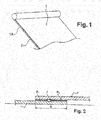
- a bituminous sealing membrane 1 designed as a sheet or strip, preferably comprises an integrated element 2 on one of its longitudinal edges 1A on an upper side of the membrane, which when the membrane 1 is laid on a surface 3 to be sealed next to another membrane 1 ' forms a canal.
- this element 2 can also be arranged on a non-longitudinally aligned edge or on two longitudinal edges of the membrane 1. It can also be arranged on the underside of the membrane 1.
- the membrane 1 is prefabricated here, the element 2 being attached to one side of the membrane before it is laid on the surface 3 to be sealed.
- This element 2 is gas-permeable and consists of a flexible material which is impervious to molten bitumen and is preferably attached during the manufacture of the membrane 1 by fusing the bitumen on one side of the membrane.
- the material is preferably refractory at a temperature of at least 300 ° C., which corresponds to the laying and welding temperature of a lap joint.
- the first membrane 1 is laid on the surface 3 to be sealed and has its integrated element 2 on the upper side essentially on the central axis of the overlap region D.
- the second membrane 1 ' is laid next to the first membrane 1 in such a way that the overlap area D results.
- the two membranes 1, 1 ' are welded with a welding device or hot air by fusing their bitumen B1, B2 on the top of the first membrane 1 and the bottom of the second membrane 1'.
- the integrated element 2 which consists essentially of a material which is resistant to temperatures of at least 300 ° C. and impervious to molten bitumen, is neither damaged nor destroyed during the fusion. To one To form a complete covering, a large number of such membranes are arranged "like scales". A plurality of corresponding overlapping areas D with integrated elements are formed.
- the integrated element 2 can also be arranged on two longitudinal edges of the membrane 1.
- the first membrane 1 is a membrane according to the invention with two integrated elements 2 and the second membrane 1 'is a conventional membrane without an integrated element 2. To form a complete covering, a large number of such membranes are arranged alternately.
- the integrated element 2 can be arranged on the underside of the membrane and according to the arrangement in FIG Figure 2 the edge of the first membrane 1 can be provided without an integrated element 2 and the edge of the second membrane 1 'can be provided with an integrated element 2.
- the integrated element 2 is preferably a cylindrical tube made of glass fiber braid or fabric. These glass fibers can be continuous or textured and twisted.
- the hose that is to say the element 2 has an inside diameter of 6 to 15 millimeters and advantageously of 10 to 12 millimeters.
- the diameter of the glass fibers is preferably greater than or equal to 6 micrometers.
- the wall thickness of the hose is advantageously essentially 0.25 millimeters.
- bituminous pavement consisting of at least two prefabricated bituminous sealing membranes 1, 1 ', which as in the Figure 2 shown are laid at one of their edges with an overlap area D, therein to blow tracer gas into the integrated element 2 forming the channel.
- the integrated element 2 is arranged between two membranes 1, 1 'in the overlap area D and a test or tracer gas, preferably a mixture of 95.5% nitrogen and 4.5% hydrogen - such as a gas called Nidron - or off Helium, is released at a pressure of 0.001 to 0.1 bar above ambient pressure or
- Atmospheric pressure and advantageously at a pressure of substantially 0.01 bar at a point of the overlap joint or region D is blown into the channel, at least one end of the channel being closed and along the overlap joint a test for the presence of certain molecules of the tracer gas in the ambient air takes place, whereby a problem with the tightness in the overlap joint or area D can be recognized by the presence of the molecules exceeding a normal threshold.
- This point can be an opening at the end of the channel, at the edge of the membrane 1 provided with an integrated element 2 or any point of the overlap joint or area D, the gas then passing through one of the strips 2A of the integrated element 2 is blown through it, for example by means of a needle.
- a rolling device for detecting the molecules in question for example nitrogen or helium, is moved along the overlap joint to detect an exit point.
- detection can take place from a threshold of 50 ppm (parts per million).
Landscapes
- Physics & Mathematics (AREA)
- Engineering & Computer Science (AREA)
- Architecture (AREA)
- General Physics & Mathematics (AREA)
- Electromagnetism (AREA)
- Civil Engineering (AREA)
- Structural Engineering (AREA)
- Revetment (AREA)
- Examining Or Testing Airtightness (AREA)
Description
- Die Erfindung betrifft ein Verfahren zur Prüfung der Dichtheit eines bituminösen Belags, der aus zumindest zwei bituminösen Abdichtungs-Membranen besteht, von denen zumindest eine zumindest an einem ihrer Ränder auf einer Seite der Membran ein Element aufweist, das, wenn die Membran auf einer abzudichtenden Fläche verlegt wurde, einen Kanal bildet, wobei das Element gasdurchlässig ist und zumindest zum Teil aus einem flexiblen und gegenüber geschmolzenem Bitumen dichten Material besteht, wobei die beiden Membranen an einem ihrer Ränder mit einem Überlappungsbereich verlegt werden und das Element zwischen den beiden Membranen in dem Überlappungsbereich angeordnet ist, wobei die Prüfung durch Einblasen von Gas in den Kanal erfolgt.
- Im Folgenden wird unter bituminöser Membran eine auf Bitumen basierende Membran oder eine auf Bitumen basierende Geomembran verstanden. Derartige Membranen sind im Allgemeinen als Streifen oder flexible Bahnen mit einer Länge von 5 bis 100 m und einer Breite zwischen 0,2 und 6 m ausgebildet und auf Rollen aufgewickelt.
- Die vorgefertigten bituminösen Abdichtungs-Streifen oder -Bahnen werden dicht zusammengefügt, indem zwei Streifen auf einer Breite von 5 bis 20 cm übereinandergelegt und mit einem Propan- oder Heißluftschweißgerät verschweißt werden, wobei diese Überlappungsbereiche, auch Überlappungsstöße genannt, eine Dichtheit aufweisen müssen, die der Dichtheit des gesamten Streifens gleichwertig ist.
- Aus der
FR 2 998 313 A1 - Gemäß dieser Schrift erfolgt ein Verfahren zur Prüfung der Dichtheit eines bituminösen Belags, bestehend aus zumindest zwei bituminösen Abdichtungs-Membranen, die an einem ihrer Ränder mit einem Überlappungsstoß verlegt sind, durch das Einblasen in den Kanal von unter Druck stehendem Gas, vorzugsweise von Luft mit einem Druck zwischen 1 und 4 bar. Das Element wird zwischen den beiden Membranen im Überlappungsstoß angeordnet und an einem Punkt des Überlappungsstoßes das unter Druck stehende Gas in den Kanal eingeblasen, wobei der Druck des Gases geprüft wird und eine Abnahme des Drucks ein Problem mit der Dichtheit im Überlappungsstoß erkennen lässt.
- Bei diesem Prüfungsverfahren tritt folgendes technische Problem auf: Der Druck der eingeblasenen Luft bewirkt, dass sich der Überlappungsstoß relativ stark verformt, was dazu führen kann, dass der Stoß, insbesondere, wenn die Umgebungstemperatur relativ hoch ist, durch den Druck reißt und die beiden Membranen sich teilweise voneinander lösen.
- Der
US 5 143 568 ist ein Verfahren zur Dichtigkeitsprüfung von sich überlappenden Dachbahnen zu entnehmen. Hierzu sind die Dachbahnen im Überlappungsbereich derart miteinander verbunden, dass sich ein Hohlraum bildet, der mit Druckluft beaufschlagt wird, um anhand der Berandung des druckbeaufschlagten Hohlraums Rückschlüsse über die Dichtheit zu ziehen. - Der
JP 2004/137880 A - Aufgabe der vorliegenden Erfindung ist es, die Nachteile des Standes der Technik zu vermeiden und ein Verfahren zur Überprüfung der Dichtheit des von abdichtenden bituminösen Lagen prüfen zu können, ohne dass sich dies nachteilig auf die Beläge und insbesondere den Überlappungsbereich auswirkt.
- Die Erfindung löst dieses Problem und schlägt dazu ein Verfahren gemäß Anspruch 1 und eine Verwendung gemäß Anspruch 6 vor.
- Auf Grund der erfindungsgemäßen Lehre kann mit einfachen Maßnahmen die Dichtheit von sich überlappenden Membranen bzw. Dachbahnen in ihren Schweißnähten ermittelt werden. Da das Gas erschnüffelt wird, kann zudem präzise die Stelle der Undichtheit ermittelt und sodann eine Reparatur vorgenommen werden.
- Das Test- oder Spürgas kann aus 95,5 % Stickstoff und 4,5 % Wasserstoff oder Helium bestehen.
- Das Test- oder Spürgas wird vorzugsweise mit einem Druck von 0,001 bis 0,1 bar und vorteilhafterweise mit einem Druck von im Wesentlichen 0,01 bar über Atmosphärendruck in den Kanal eingeblasen.
- Die Erfindung betrifft darüber hinaus eine bituminöse Abdichtungsmembran für die Umsetzung eines derartigen Verfahrens, wobei das Element ein Schlauch, insbesondere zylindrischer Schlauch, aus Glasfasergeflecht oder -gewebe ist.
- Der Schlauch kann einen Innendurchmesser von vorteilhafterweise 10 bis 12 Millimeter aufweisen.
- Der Durchmesser der Glasfasern ist vorzugsweise größer oder gleich 6 Mikrometer.
- Die Wanddicke des Schlauchs beträgt vorteilhafterweise im Wesentlichen 0,25 Millimeter.
- Dank dieser Abmessungen wird sichergestellt, dass das durch die Flamme des Brenners geschmolzene und in den flüssigen Zustand gebrachte Bitumen während des Verschweißens des Überlappungsstoßes nicht in das Element wie den Schlauch gelangt, dieser jedoch das Gas durchlässt.
- Der integrierte Schlauch ist vorzugsweise an nur einem Längsrand der Membran angeordnet.
- Der integrierte Schlauch ist vorzugsweise auf der Oberseite der Membran angeordnet, d.h. auf der Seite der verlegten Membran, die zu dem abzudichtenden Bauwerk abgewandt verläuft.
- Die Membran ist vorzugsweise vorgefertigt, wobei der Schlauch auf der einen Seite der Membran befestigt wurde, bevor diese auf der abzudichtenden Fläche verlegt wird.
- Weitere Einzelheiten, Vorteile und Merkmale der Erfindung ergeben sich nicht nur aus den Ansprüchen, den diesen zu entnehmenden Merkmalen -für sich und/oder in Kombination-, sondern auch aus der nachfolgenden Beschreibung von der Zeichnung zu entnehmenden bevorzugten Ausführungsbeispielen.
- Die Erfindung wird nachstehend anhand der Figuren, die nur eine bevorzugte Ausführungsform der Erfindung zeigen, detaillierter beschrieben.
- Die
Figur 1 zeigt eine Ansicht einer erfindungsgemäßen Membran. - Die
Figur 2 zeigt eine Teilansicht eines Querschnitts zweier erfindungsgemäßer Membranen, die auf einer abzudichtenden Fläche verlegt werden, wie z.B. Dach, insbesondere Flachdach, bekiestes Dach, Terrasse, Balkon. Die Membrane können aber auch z.B. zur Abdichtung von Deponien benutzt werden. - Wie in der
Figur 1 gezeigt, umfasst eine erfindungsgemäße, als Bahn oder Streifen ausgebildete bituminöse Abdichtungs-Membran 1 vorzugsweise an einem ihrer Längsränder 1A auf einer Oberseite der Membran ein integriertes Element 2, das, wenn die Membran 1 auf einer abzudichtenden Fläche 3 neben einer anderen Membran 1' verlegt wurde, einen Kanal bildet. - Ebenfalls erfindungsgemäß kann dieses Element 2 auch an einem nicht längs ausgerichteten Rand oder an zwei Längsrändem der Membran 1 angeordnet werden. Es kann auch auf der Unterseite der Membran 1 angeordnet werden.
- Die Membran 1 ist hier vorgefertigt, wobei das Element 2 auf der einen Seite der Membran befestigt wurde, bevor diese auf der abzudichtenden Fläche 3 verlegt wird.
- Dieses Element 2 ist gasdurchlässig und besteht aus einem flexiblen und gegenüber geschmolzenem Bitumen dichten Material und wird vorzugsweise während der Herstellung der Membran 1 durch Verschmelzen des Bitumens auf der einen Seite der Membran befestigt. Das Material ist vorzugsweise bei einer Temperatur von mindestens 300 °C, die der Auslege- und Verschweißtemperatur eines Überlappungsstoßes entspricht, feuerfest.
- Das Verlegen derartiger Membranen auf einer abzudichtenden Fläche wird in der
Figur 2 dargestellt, in der zwei erfindungsgemäße Membranen 1, 1' teilweise dargestellt sind. - Die erste Membran 1 wird auf der abzudichtenden Fläche 3 verlegt und weist sein integriertes Element 2 auf der Oberseite im Wesentlichen auf der Mittelachse des Überlappungsbereiches D auf. Um den Belag zum Abdichten zu bilden, wird die zweite Membran 1' neben der ersten Membran 1 derart verlegt, dass sich der Überlappungsbereich D ergibt. In diesem Überlappungsbereich D werden die beiden Membranen 1, 1' mit einem Schweißgerät oder heißer Luft durch das Verschmelzen ihres Bitumens B1, B2 auf der Oberseite der ersten Membran 1 und der Unterseite der zweiten Membran 1' verschweißt.
- Das integrierte Element 2, das im Wesentlichen aus einem bei Temperaturen bis zu mindestens 300 °C beständigen und gegenüber geschmolzenem Bitumen dichten Material besteht, wird während des Verschmelzens weder beschädigt noch zerstört. Um einen kompletten Belag zu bilden, wird eine Vielzahl derartiger Membranen »schuppenartig« angeordnet. Eine Vielzahl von entsprechenden Überlappungsbereichen D mit integrierten Elementen werden gebildet.
- Wie vorstehend ausgeführt, kann das integrierte Element 2 auch an zwei Längsrändern der Membran 1 angeordnet sein. In diesem Fall ist die erste Membran 1 eine erfindungsgemäße Membran mit zwei integrierten Elementen 2 und die zweite Membran 1' ist eine konventionelle Membran ohne integriertes Element 2. Um einen kompletten Belag zu bilden, wird eine Vielzahl derartiger Membranen abwechselnd angeordnet.
- Wie ebenfalls vorstehend ausgeführt, kann das integrierte Element 2 auf der Unterseite der Membran angeordnet sein und gemäß der Anordnung in
Figur 2 der Rand der ersten Membran 1 ohne ein integriertes Element 2 und der Rand der zweiten Membran 1' mit einem integrierten Element 2 versehen sein. - Das integrierte Element 2 ist vorzugsweise ein zylindrischer Schlauch aus Glasfasergeflecht bzw. -gewebe. Diese Glasfasern können durchgehend oder texturiert und verdrillt sein.
- Der Schlauch, also das Element 2, weist einen Innendurchmesser von 6 bis 15 Millimeter und vorteilhafterweise von 10 bis 12 Millimeter auf. Der Durchmesser der Glasfasern ist vorzugsweise größer oder gleich 6 Mikrometer. Die Wanddicke des Schlauchs beträgt vorteilhafterweise im Wesentlichen 0,25 Millimeter.
- Gemäß der Erfindung besteht ein Verfahren zur Prüfung der Dichtheit eines bituminösen Belags bestehend aus zumindest zwei vorgefertigten bituminösen Abdichtungs-Membranen 1, 1', die wie in der
Figur 2 dargestellt an einem ihrer Ränder mit einem Überlappungsbereich D verlegt sind, darin, Spürgas in das den Kanal bildende integrierte Element 2 einzublasen. - Das integrierte Element 2 ist zwischen zwei Membranen 1, 1' in dem Überlappungsbereich D angeordnet und ein Test- oder Spürgas, vorzugsweise eine Mischung aus 95,5 % Stickstoff und 4,5 % Wasserstoff - wie ein Gas mit der Bezeichnung Nidron - oder aus Helium, wird bei einem Druck von 0,001 bis 0,1 bar über Umgebungsdruck bzw.
- Atmosphärendruck und vorteilhafterweise bei einem Druck von im Wesentlichen 0,01 bar an einem Punkt des Überlappungsstoßes bzw. -bereiches D in den Kanal eingeblasen, wobei zumindest ein Ende des Kanals verschlossen ist und entlang des Überlappungsstoßes eine Prüfung auf das Vorhandensein bestimmter Moleküle des Spürgases in der Umgebungsluft stattfindet, wobei durch das eine normale Schwelle übersteigende Vorhandensein der Moleküle ein Problem mit der Dichtheit im Überlappungsstoß bzw. -bereich D erkannt werden kann.
- Bei diesem Punkt kann es sich um eine Öffnung am Endes des Kanals, am Rand der mit einem integrierten Element 2 versehenen Membran 1 oder einen beliebigen Punkt des Überlappungsstoßes bzw. -bereiches D handeln, wobei das Gas dann durch einen der Streifen 2A des integrierten Elements 2 hindurch, zum Beispiel mittels einer Nadel, eingeblasen wird.
- Eine zum Beispiel rollende Vorrichtung zur Erkennung der betreffenden Moleküle, zum Beispiel Stickstoff oder Helium, wird zur Erkennung einer Austrittstelle entlang des Überlappungsstoßes bewegt. So kann beispielsweise ab einer Schwelle von 50 ppm (Anteile pro Millionen) eine Erkennung stattfinden.
Claims (12)
- Verfahren zur Prüfung der Dichtheit eines bituminösen Belags, der aus zumindest zwei bituminösen Abdichtungs-Membranen (1, 1') besteht, von denen zumindest eine zumindest an einem ihrer Ränder (1A) auf einer Seite der Membran ein Element (2) aufweist, das, wenn die Membran auf einer abzudichtenden Fläche verlegt wurde, einen Kanal bildet, wobei das Element gasdurchlässig ist und zumindest zum Teil aus einem flexiblen und gegenüber geschmolzenem Bitumen dichten Material besteht, wobei die beiden Membranen an einem ihrer Ränder mit einem Überlappungsbereich (D) verlegt werden und das Element zwischen den beiden Membranen in dem Überlappungsbereich (D) angeordnet ist, wobei die Prüfung durch Einblasen von Gas in den Kanal erfolgt, wobei das Element (2) ein Schlauch aus Glasfasergeflecht oder -gewebe ist, dadurch gekennzeichnet,
dass der Schlauch einen Innendurchmesser von 6 mm bis 15 mm aufweist, und dass in den Kanal an einem Punkt des Überlappungsbereiches D ein Test- oder Spürgas eingeblasen wird und entlang des Überlappungsbereiches (D) eine Prüfung auf das Vorhandensein bestimmter Moleküle des Test- oder Spürgases in der Umgebungsluft stattfindet, wobei durch das eine normale Schwelle übersteigende Vorhandensein der Moleküle ein Problem mit der Dichtheit im Überlappungsbereich erkennen lässt. - Verfahren nach Anspruch 1,
dadurch gekennzeichnet,
dass das Test- oder Spürgas aus 95,5 % Stickstoff und 4,5 % Wasserstoff besteht. - Verfahren nach Anspruch 1,
dadurch gekennzeichnet,
dass das Test- oder Spürgas Helium enthält oder aus Helium besteht. - Verfahren nach einem der voranstehenden Ansprüche,
dadurch gekennzeichnet,
dass das Test- oder Spürgas mit einem Druck von 0,001 bis 0,1 bar über Atmosphärendruck in den Kanal eingeblasen wird. - Verfahren nach dem voranstehenden Anspruch,
dadurch gekennzeichnet,
dass das Test- oder Spürgas mit einem Druck von im Wesentlichen 0,01 bar über Atmosphärendruck in den Kanal eingeblasen wird. - Verwendung eines Schlauchs aus Glasfasergeflecht oder -gewebe mit einem Innendurchmesser von 6 mm bis 15 mm zur Durchführung des Verfahrens nach zumindest Anspruch 1 zur Prüfung der Dichtheit eines bituminösen Belags.
- Verwendung nach Anspruch 6,
dadurch gekennzeichnet,
dass der Schlauch einen Innendurchmesser von 10 bis 12 Millimeter aufweist. - Verwendung nach einem der Ansprüche 6 und 7,
dadurch gekennzeichnet,
dass der Durchmesser der Glasfaser größer oder gleich 6 Mikrometer ist. - Verwendung nach Anspruch 6,
dadurch gekennzeichnet,
dass die Wanddicke des Schlauchs im Wesentlichen 0,25 Millimeter beträgt. - Verwendung nach einem der Ansprüche 6 bis 9,
dadurch gekennzeichnet,
dass der Schlauch an nur einem Längsrand (1A) der Membran (1) angeordnet ist. - Verwendung nach einem der Ansprüche 6 bis 10,
dadurch gekennzeichnet,
dass der Schlauch auf der Oberseite der Membran (1) angeordnet ist. - Verwendung nach einem der Ansprüche 6 bis 11,
dadurch gekennzeichnet,
dass die Membran (1) vorgefertigt ist, wobei der Schlauch auf der einen Seite der Membran (1) befestigt wurde, bevor diese auf der abzudichtenden Fläche verlegt wird.
Priority Applications (1)
| Application Number | Priority Date | Filing Date | Title |
|---|---|---|---|
| PL18189495T PL3450641T3 (pl) | 2017-08-28 | 2018-08-17 | Sposób sprawdzania szczelności powłoki bitumicznej |
Applications Claiming Priority (1)
| Application Number | Priority Date | Filing Date | Title |
|---|---|---|---|
| FR1757923A FR3070488B1 (fr) | 2017-08-28 | 2017-08-28 | Procede de controle de l'etancheite d'un revetement bitumineux et membrane ou geomembrane d'etancheite bitumineuse pour sa mise en oeuvre |
Publications (2)
| Publication Number | Publication Date |
|---|---|
| EP3450641A1 EP3450641A1 (de) | 2019-03-06 |
| EP3450641B1 true EP3450641B1 (de) | 2021-03-24 |
Family
ID=60020169
Family Applications (1)
| Application Number | Title | Priority Date | Filing Date |
|---|---|---|---|
| EP18189495.7A Active EP3450641B1 (de) | 2017-08-28 | 2018-08-17 | Verfahren zur prüfung der dichtheit eines bituminösen belags |
Country Status (3)
| Country | Link |
|---|---|
| EP (1) | EP3450641B1 (de) |
| FR (1) | FR3070488B1 (de) |
| PL (1) | PL3450641T3 (de) |
Family Cites Families (3)
| Publication number | Priority date | Publication date | Assignee | Title |
|---|---|---|---|---|
| US5143568A (en) * | 1989-10-25 | 1992-09-01 | J.P. Sheahan & Associates | Method for leak detection and non-destructive quality control testing for roofing seams |
| JP2004137880A (ja) * | 2002-09-27 | 2004-05-13 | Mitsuboshi Belting Ltd | 遮水シートの接合方法および接合構造 |
| FR2998313B1 (fr) * | 2012-11-19 | 2015-03-20 | Icopal Sas | Membrane ou geomembrane d'etancheite bitumineuse prefabriquee |
-
2017
- 2017-08-28 FR FR1757923A patent/FR3070488B1/fr not_active Expired - Fee Related
-
2018
- 2018-08-17 PL PL18189495T patent/PL3450641T3/pl unknown
- 2018-08-17 EP EP18189495.7A patent/EP3450641B1/de active Active
Non-Patent Citations (1)
| Title |
|---|
| None * |
Also Published As
| Publication number | Publication date |
|---|---|
| FR3070488A1 (fr) | 2019-03-01 |
| FR3070488B1 (fr) | 2020-05-29 |
| PL3450641T3 (pl) | 2021-10-04 |
| EP3450641A1 (de) | 2019-03-06 |
Similar Documents
| Publication | Publication Date | Title |
|---|---|---|
| DE3706869C2 (de) | ||
| WO1993021399A1 (de) | System und verfahren zum relining von kanalrohrabschnitten | |
| DE2921707A1 (de) | Leckdetektionseinrichtung | |
| DE4302027A1 (de) | ||
| DE2832146C2 (de) | Verfahren zum Verbinden der Ränder von zwei flächigen Gegenständen, insbesondere Bahnen, aus thermoplastischem Werkstoff | |
| WO2018206247A1 (de) | Nageldichte unterdachbahn | |
| EP2339088A2 (de) | Dampfbremse oder Dampfsperre zur Ausbildung als Manschettenvorrichtung für eine luftdichte Abdichtung einer bereits verlegten Dampfbremse oder Dampfsperre und Verfahren zum Herstellen einer Manschettenvorrichtung | |
| EP2612549A2 (de) | Abdichtungssystem für Innenflächen von Betonseitenwänden von Siloanlagen, Siloanlage mit demselben, Verfahren zur Herstellung des Abdichtungssystems und Verfahren zum Überprüfen des Dichtigkeitszustands einer derartigen Siloanlage | |
| DE102007017206B3 (de) | Mehrschicht-Paneel zur Auskleidung von Flüssig-Gas-Behältern, Verwendung des Paneels und hieraus aufgebaute Auskleidung | |
| EP3450641A1 (de) | Verfahren zur prüfung der dichtheit eines bituminösen belags und eine bituminöse abdichtungs-membran oder geomembran zur umsetzung des verfahrens | |
| DE202015004236U1 (de) | Bituminöse Dachabdichtungsbahn | |
| DE19650883A1 (de) | Verfahren zum berührungslosen und zerstörungsfreien Prüfen von Schweißnähten an bewegten Bahnen | |
| DE102009044261A1 (de) | Verfahren zur Herstellung eines mehrlagigen Dichtungsaufbaus aus Bitumenschweißbahnen mit elektrisch leitfähiger Innenschicht und Bitumenschweißbahnen für einen solchen Dichtungsaufbau | |
| DE4104705C2 (de) | Mehrlagige Abdichtung für Tunnel | |
| DE10197184T5 (de) | Folienschweißvorrichtung und Schweißverfahren dafür | |
| EP2527530B2 (de) | Bituminöse Dachbahn | |
| DE102021134432A1 (de) | Selbstklebendes dichtungsband mit hilfslinien | |
| EP4050176A1 (de) | Verfahren zum herstellen einer durchführung durch einen dachbelag | |
| CH675850A5 (de) | ||
| EP0359988A2 (de) | Fugenverbindung zweier gekrümmter Flächen mit Übergang zu einer geraden Fläche | |
| DE10318724B4 (de) | Mess-Vorrichtung und ein Verfahren zur Qualitätssicherung von mehrschichtigen textilen Halbzeugen für die Herstellung von Kunststoffbauteilen | |
| DE4411745C1 (de) | Wärmetauscher | |
| EP0240596B1 (de) | Thermoplastische Abdichtungsbahn | |
| DE3624573A1 (de) | Verfahren zum kontinuierlichen ueberlappungsverschweissen von grossflaechigen kunststoff-folien oder -platten | |
| DE3717586C2 (de) | Deponieabdichtung |
Legal Events
| Date | Code | Title | Description |
|---|---|---|---|
| PUAI | Public reference made under article 153(3) epc to a published international application that has entered the european phase |
Free format text: ORIGINAL CODE: 0009012 |
|
| STAA | Information on the status of an ep patent application or granted ep patent |
Free format text: STATUS: THE APPLICATION HAS BEEN PUBLISHED |
|
| STAA | Information on the status of an ep patent application or granted ep patent |
Free format text: STATUS: REQUEST FOR EXAMINATION WAS MADE |
|
| AK | Designated contracting states |
Kind code of ref document: A1 Designated state(s): AL AT BE BG CH CY CZ DE DK EE ES FI FR GB GR HR HU IE IS IT LI LT LU LV MC MK MT NL NO PL PT RO RS SE SI SK SM TR |
|
| AX | Request for extension of the european patent |
Extension state: BA ME |
|
| 17P | Request for examination filed |
Effective date: 20190225 |
|
| RBV | Designated contracting states (corrected) |
Designated state(s): AL AT BE BG CH CY CZ DE DK EE ES FI FR GB GR HR HU IE IS IT LI LT LU LV MC MK MT NL NO PL PT RO RS SE SI SK SM TR |
|
| STAA | Information on the status of an ep patent application or granted ep patent |
Free format text: STATUS: EXAMINATION IS IN PROGRESS |
|
| 17Q | First examination report despatched |
Effective date: 20190821 |
|
| GRAP | Despatch of communication of intention to grant a patent |
Free format text: ORIGINAL CODE: EPIDOSNIGR1 |
|
| STAA | Information on the status of an ep patent application or granted ep patent |
Free format text: STATUS: GRANT OF PATENT IS INTENDED |
|
| INTG | Intention to grant announced |
Effective date: 20201005 |
|
| GRAS | Grant fee paid |
Free format text: ORIGINAL CODE: EPIDOSNIGR3 |
|
| GRAA | (expected) grant |
Free format text: ORIGINAL CODE: 0009210 |
|
| STAA | Information on the status of an ep patent application or granted ep patent |
Free format text: STATUS: THE PATENT HAS BEEN GRANTED |
|
| AK | Designated contracting states |
Kind code of ref document: B1 Designated state(s): AL AT BE BG CH CY CZ DE DK EE ES FI FR GB GR HR HU IE IS IT LI LT LU LV MC MK MT NL NO PL PT RO RS SE SI SK SM TR |
|
| REG | Reference to a national code |
Ref country code: GB Ref legal event code: FG4D Free format text: NOT ENGLISH |
|
| REG | Reference to a national code |
Ref country code: CH Ref legal event code: EP |
|
| REG | Reference to a national code |
Ref country code: IE Ref legal event code: FG4D Free format text: LANGUAGE OF EP DOCUMENT: GERMAN |
|
| REG | Reference to a national code |
Ref country code: AT Ref legal event code: REF Ref document number: 1374647 Country of ref document: AT Kind code of ref document: T Effective date: 20210415 Ref country code: DE Ref legal event code: R096 Ref document number: 502018004412 Country of ref document: DE |
|
| REG | Reference to a national code |
Ref country code: NL Ref legal event code: FP |
|
| REG | Reference to a national code |
Ref country code: SE Ref legal event code: TRGR |
|
| REG | Reference to a national code |
Ref country code: LT Ref legal event code: MG9D |
|
| PG25 | Lapsed in a contracting state [announced via postgrant information from national office to epo] |
Ref country code: NO Free format text: LAPSE BECAUSE OF FAILURE TO SUBMIT A TRANSLATION OF THE DESCRIPTION OR TO PAY THE FEE WITHIN THE PRESCRIBED TIME-LIMIT Effective date: 20210624 Ref country code: GR Free format text: LAPSE BECAUSE OF FAILURE TO SUBMIT A TRANSLATION OF THE DESCRIPTION OR TO PAY THE FEE WITHIN THE PRESCRIBED TIME-LIMIT Effective date: 20210625 Ref country code: HR Free format text: LAPSE BECAUSE OF FAILURE TO SUBMIT A TRANSLATION OF THE DESCRIPTION OR TO PAY THE FEE WITHIN THE PRESCRIBED TIME-LIMIT Effective date: 20210324 Ref country code: FI Free format text: LAPSE BECAUSE OF FAILURE TO SUBMIT A TRANSLATION OF THE DESCRIPTION OR TO PAY THE FEE WITHIN THE PRESCRIBED TIME-LIMIT Effective date: 20210324 Ref country code: BG Free format text: LAPSE BECAUSE OF FAILURE TO SUBMIT A TRANSLATION OF THE DESCRIPTION OR TO PAY THE FEE WITHIN THE PRESCRIBED TIME-LIMIT Effective date: 20210624 |
|
| PG25 | Lapsed in a contracting state [announced via postgrant information from national office to epo] |
Ref country code: RS Free format text: LAPSE BECAUSE OF FAILURE TO SUBMIT A TRANSLATION OF THE DESCRIPTION OR TO PAY THE FEE WITHIN THE PRESCRIBED TIME-LIMIT Effective date: 20210324 Ref country code: LV Free format text: LAPSE BECAUSE OF FAILURE TO SUBMIT A TRANSLATION OF THE DESCRIPTION OR TO PAY THE FEE WITHIN THE PRESCRIBED TIME-LIMIT Effective date: 20210324 |
|
| PG25 | Lapsed in a contracting state [announced via postgrant information from national office to epo] |
Ref country code: SM Free format text: LAPSE BECAUSE OF FAILURE TO SUBMIT A TRANSLATION OF THE DESCRIPTION OR TO PAY THE FEE WITHIN THE PRESCRIBED TIME-LIMIT Effective date: 20210324 Ref country code: CZ Free format text: LAPSE BECAUSE OF FAILURE TO SUBMIT A TRANSLATION OF THE DESCRIPTION OR TO PAY THE FEE WITHIN THE PRESCRIBED TIME-LIMIT Effective date: 20210324 Ref country code: EE Free format text: LAPSE BECAUSE OF FAILURE TO SUBMIT A TRANSLATION OF THE DESCRIPTION OR TO PAY THE FEE WITHIN THE PRESCRIBED TIME-LIMIT Effective date: 20210324 Ref country code: LT Free format text: LAPSE BECAUSE OF FAILURE TO SUBMIT A TRANSLATION OF THE DESCRIPTION OR TO PAY THE FEE WITHIN THE PRESCRIBED TIME-LIMIT Effective date: 20210324 |
|
| PG25 | Lapsed in a contracting state [announced via postgrant information from national office to epo] |
Ref country code: IS Free format text: LAPSE BECAUSE OF FAILURE TO SUBMIT A TRANSLATION OF THE DESCRIPTION OR TO PAY THE FEE WITHIN THE PRESCRIBED TIME-LIMIT Effective date: 20210724 Ref country code: PT Free format text: LAPSE BECAUSE OF FAILURE TO SUBMIT A TRANSLATION OF THE DESCRIPTION OR TO PAY THE FEE WITHIN THE PRESCRIBED TIME-LIMIT Effective date: 20210726 Ref country code: RO Free format text: LAPSE BECAUSE OF FAILURE TO SUBMIT A TRANSLATION OF THE DESCRIPTION OR TO PAY THE FEE WITHIN THE PRESCRIBED TIME-LIMIT Effective date: 20210324 Ref country code: SK Free format text: LAPSE BECAUSE OF FAILURE TO SUBMIT A TRANSLATION OF THE DESCRIPTION OR TO PAY THE FEE WITHIN THE PRESCRIBED TIME-LIMIT Effective date: 20210324 |
|
| REG | Reference to a national code |
Ref country code: DE Ref legal event code: R097 Ref document number: 502018004412 Country of ref document: DE |
|
| PG25 | Lapsed in a contracting state [announced via postgrant information from national office to epo] |
Ref country code: ES Free format text: LAPSE BECAUSE OF FAILURE TO SUBMIT A TRANSLATION OF THE DESCRIPTION OR TO PAY THE FEE WITHIN THE PRESCRIBED TIME-LIMIT Effective date: 20210324 Ref country code: AL Free format text: LAPSE BECAUSE OF FAILURE TO SUBMIT A TRANSLATION OF THE DESCRIPTION OR TO PAY THE FEE WITHIN THE PRESCRIBED TIME-LIMIT Effective date: 20210324 Ref country code: DK Free format text: LAPSE BECAUSE OF FAILURE TO SUBMIT A TRANSLATION OF THE DESCRIPTION OR TO PAY THE FEE WITHIN THE PRESCRIBED TIME-LIMIT Effective date: 20210324 |
|
| PLBE | No opposition filed within time limit |
Free format text: ORIGINAL CODE: 0009261 |
|
| STAA | Information on the status of an ep patent application or granted ep patent |
Free format text: STATUS: NO OPPOSITION FILED WITHIN TIME LIMIT |
|
| PG25 | Lapsed in a contracting state [announced via postgrant information from national office to epo] |
Ref country code: SI Free format text: LAPSE BECAUSE OF FAILURE TO SUBMIT A TRANSLATION OF THE DESCRIPTION OR TO PAY THE FEE WITHIN THE PRESCRIBED TIME-LIMIT Effective date: 20210324 |
|
| 26N | No opposition filed |
Effective date: 20220104 |
|
| REG | Reference to a national code |
Ref country code: CH Ref legal event code: PL |
|
| PG25 | Lapsed in a contracting state [announced via postgrant information from national office to epo] |
Ref country code: MC Free format text: LAPSE BECAUSE OF FAILURE TO SUBMIT A TRANSLATION OF THE DESCRIPTION OR TO PAY THE FEE WITHIN THE PRESCRIBED TIME-LIMIT Effective date: 20210324 |
|
| PG25 | Lapsed in a contracting state [announced via postgrant information from national office to epo] |
Ref country code: LI Free format text: LAPSE BECAUSE OF NON-PAYMENT OF DUE FEES Effective date: 20210831 Ref country code: CH Free format text: LAPSE BECAUSE OF NON-PAYMENT OF DUE FEES Effective date: 20210831 |
|
| PG25 | Lapsed in a contracting state [announced via postgrant information from national office to epo] |
Ref country code: IS Free format text: LAPSE BECAUSE OF FAILURE TO SUBMIT A TRANSLATION OF THE DESCRIPTION OR TO PAY THE FEE WITHIN THE PRESCRIBED TIME-LIMIT Effective date: 20210724 Ref country code: LU Free format text: LAPSE BECAUSE OF NON-PAYMENT OF DUE FEES Effective date: 20210817 |
|
| PG25 | Lapsed in a contracting state [announced via postgrant information from national office to epo] |
Ref country code: IE Free format text: LAPSE BECAUSE OF NON-PAYMENT OF DUE FEES Effective date: 20210817 |
|
| PG25 | Lapsed in a contracting state [announced via postgrant information from national office to epo] |
Ref country code: IT Free format text: LAPSE BECAUSE OF FAILURE TO SUBMIT A TRANSLATION OF THE DESCRIPTION OR TO PAY THE FEE WITHIN THE PRESCRIBED TIME-LIMIT Effective date: 20210324 |
|
| PG25 | Lapsed in a contracting state [announced via postgrant information from national office to epo] |
Ref country code: CY Free format text: LAPSE BECAUSE OF FAILURE TO SUBMIT A TRANSLATION OF THE DESCRIPTION OR TO PAY THE FEE WITHIN THE PRESCRIBED TIME-LIMIT Effective date: 20210324 |
|
| P01 | Opt-out of the competence of the unified patent court (upc) registered |
Effective date: 20230527 |
|
| PG25 | Lapsed in a contracting state [announced via postgrant information from national office to epo] |
Ref country code: HU Free format text: LAPSE BECAUSE OF FAILURE TO SUBMIT A TRANSLATION OF THE DESCRIPTION OR TO PAY THE FEE WITHIN THE PRESCRIBED TIME-LIMIT; INVALID AB INITIO Effective date: 20180817 |
|
| PG25 | Lapsed in a contracting state [announced via postgrant information from national office to epo] |
Ref country code: MK Free format text: LAPSE BECAUSE OF FAILURE TO SUBMIT A TRANSLATION OF THE DESCRIPTION OR TO PAY THE FEE WITHIN THE PRESCRIBED TIME-LIMIT Effective date: 20210324 |
|
| PG25 | Lapsed in a contracting state [announced via postgrant information from national office to epo] |
Ref country code: TR Free format text: LAPSE BECAUSE OF FAILURE TO SUBMIT A TRANSLATION OF THE DESCRIPTION OR TO PAY THE FEE WITHIN THE PRESCRIBED TIME-LIMIT Effective date: 20210324 |
|
| PG25 | Lapsed in a contracting state [announced via postgrant information from national office to epo] |
Ref country code: MT Free format text: LAPSE BECAUSE OF FAILURE TO SUBMIT A TRANSLATION OF THE DESCRIPTION OR TO PAY THE FEE WITHIN THE PRESCRIBED TIME-LIMIT Effective date: 20210324 |
|
| REG | Reference to a national code |
Ref country code: AT Ref legal event code: MM01 Ref document number: 1374647 Country of ref document: AT Kind code of ref document: T Effective date: 20230817 |
|
| PG25 | Lapsed in a contracting state [announced via postgrant information from national office to epo] |
Ref country code: AT Free format text: LAPSE BECAUSE OF NON-PAYMENT OF DUE FEES Effective date: 20230817 |
|
| PG25 | Lapsed in a contracting state [announced via postgrant information from national office to epo] |
Ref country code: AT Free format text: LAPSE BECAUSE OF NON-PAYMENT OF DUE FEES Effective date: 20230817 |
|
| PGFP | Annual fee paid to national office [announced via postgrant information from national office to epo] |
Ref country code: NL Payment date: 20250821 Year of fee payment: 8 |
|
| PGFP | Annual fee paid to national office [announced via postgrant information from national office to epo] |
Ref country code: DE Payment date: 20250819 Year of fee payment: 8 |
|
| PGFP | Annual fee paid to national office [announced via postgrant information from national office to epo] |
Ref country code: PL Payment date: 20250804 Year of fee payment: 8 |
|
| PGFP | Annual fee paid to national office [announced via postgrant information from national office to epo] |
Ref country code: BE Payment date: 20250820 Year of fee payment: 8 Ref country code: GB Payment date: 20250822 Year of fee payment: 8 |
|
| PGFP | Annual fee paid to national office [announced via postgrant information from national office to epo] |
Ref country code: FR Payment date: 20250821 Year of fee payment: 8 |
|
| PGFP | Annual fee paid to national office [announced via postgrant information from national office to epo] |
Ref country code: SE Payment date: 20250821 Year of fee payment: 8 |
|
| PGFP | Annual fee paid to national office [announced via postgrant information from national office to epo] |
Ref country code: AT Payment date: 20260410 Year of fee payment: 5 |