EP3450638A1 - Commande d'un réseau de distribution d'eau - Google Patents
Commande d'un réseau de distribution d'eau Download PDFInfo
- Publication number
- EP3450638A1 EP3450638A1 EP17188473.7A EP17188473A EP3450638A1 EP 3450638 A1 EP3450638 A1 EP 3450638A1 EP 17188473 A EP17188473 A EP 17188473A EP 3450638 A1 EP3450638 A1 EP 3450638A1
- Authority
- EP
- European Patent Office
- Prior art keywords
- water
- components
- edge
- time
- supply network
- Prior art date
- Legal status (The legal status is an assumption and is not a legal conclusion. Google has not performed a legal analysis and makes no representation as to the accuracy of the status listed.)
- Ceased
Links
Images
Classifications
-
- G—PHYSICS
- G05—CONTROLLING; REGULATING
- G05B—CONTROL OR REGULATING SYSTEMS IN GENERAL; FUNCTIONAL ELEMENTS OF SUCH SYSTEMS; MONITORING OR TESTING ARRANGEMENTS FOR SUCH SYSTEMS OR ELEMENTS
- G05B19/00—Programme-control systems
- G05B19/02—Programme-control systems electric
- G05B19/04—Programme control other than numerical control, i.e. in sequence controllers or logic controllers
- G05B19/042—Programme control other than numerical control, i.e. in sequence controllers or logic controllers using digital processors
-
- E—FIXED CONSTRUCTIONS
- E03—WATER SUPPLY; SEWERAGE
- E03B—INSTALLATIONS OR METHODS FOR OBTAINING, COLLECTING, OR DISTRIBUTING WATER
- E03B7/00—Water main or service pipe systems
-
- E—FIXED CONSTRUCTIONS
- E03—WATER SUPPLY; SEWERAGE
- E03B—INSTALLATIONS OR METHODS FOR OBTAINING, COLLECTING, OR DISTRIBUTING WATER
- E03B7/00—Water main or service pipe systems
- E03B7/07—Arrangement of devices, e.g. filters, flow controls, measuring devices, siphons, valves, in the pipe systems
-
- G—PHYSICS
- G05—CONTROLLING; REGULATING
- G05B—CONTROL OR REGULATING SYSTEMS IN GENERAL; FUNCTIONAL ELEMENTS OF SUCH SYSTEMS; MONITORING OR TESTING ARRANGEMENTS FOR SUCH SYSTEMS OR ELEMENTS
- G05B15/00—Systems controlled by a computer
- G05B15/02—Systems controlled by a computer electric
-
- G—PHYSICS
- G06—COMPUTING; CALCULATING OR COUNTING
- G06Q—INFORMATION AND COMMUNICATION TECHNOLOGY [ICT] SPECIALLY ADAPTED FOR ADMINISTRATIVE, COMMERCIAL, FINANCIAL, MANAGERIAL OR SUPERVISORY PURPOSES; SYSTEMS OR METHODS SPECIALLY ADAPTED FOR ADMINISTRATIVE, COMMERCIAL, FINANCIAL, MANAGERIAL OR SUPERVISORY PURPOSES, NOT OTHERWISE PROVIDED FOR
- G06Q10/00—Administration; Management
- G06Q10/06—Resources, workflows, human or project management; Enterprise or organisation planning; Enterprise or organisation modelling
- G06Q10/063—Operations research, analysis or management
- G06Q10/0631—Resource planning, allocation, distributing or scheduling for enterprises or organisations
-
- G—PHYSICS
- G06—COMPUTING; CALCULATING OR COUNTING
- G06Q—INFORMATION AND COMMUNICATION TECHNOLOGY [ICT] SPECIALLY ADAPTED FOR ADMINISTRATIVE, COMMERCIAL, FINANCIAL, MANAGERIAL OR SUPERVISORY PURPOSES; SYSTEMS OR METHODS SPECIALLY ADAPTED FOR ADMINISTRATIVE, COMMERCIAL, FINANCIAL, MANAGERIAL OR SUPERVISORY PURPOSES, NOT OTHERWISE PROVIDED FOR
- G06Q10/00—Administration; Management
- G06Q10/06—Resources, workflows, human or project management; Enterprise or organisation planning; Enterprise or organisation modelling
- G06Q10/063—Operations research, analysis or management
- G06Q10/0637—Strategic management or analysis, e.g. setting a goal or target of an organisation; Planning actions based on goals; Analysis or evaluation of effectiveness of goals
-
- G—PHYSICS
- G06—COMPUTING; CALCULATING OR COUNTING
- G06Q—INFORMATION AND COMMUNICATION TECHNOLOGY [ICT] SPECIALLY ADAPTED FOR ADMINISTRATIVE, COMMERCIAL, FINANCIAL, MANAGERIAL OR SUPERVISORY PURPOSES; SYSTEMS OR METHODS SPECIALLY ADAPTED FOR ADMINISTRATIVE, COMMERCIAL, FINANCIAL, MANAGERIAL OR SUPERVISORY PURPOSES, NOT OTHERWISE PROVIDED FOR
- G06Q50/00—Systems or methods specially adapted for specific business sectors, e.g. utilities or tourism
- G06Q50/06—Electricity, gas or water supply
-
- E—FIXED CONSTRUCTIONS
- E03—WATER SUPPLY; SEWERAGE
- E03B—INSTALLATIONS OR METHODS FOR OBTAINING, COLLECTING, OR DISTRIBUTING WATER
- E03B7/00—Water main or service pipe systems
- E03B7/02—Public or like main pipe systems
-
- G—PHYSICS
- G05—CONTROLLING; REGULATING
- G05B—CONTROL OR REGULATING SYSTEMS IN GENERAL; FUNCTIONAL ELEMENTS OF SUCH SYSTEMS; MONITORING OR TESTING ARRANGEMENTS FOR SUCH SYSTEMS OR ELEMENTS
- G05B2219/00—Program-control systems
- G05B2219/20—Pc systems
- G05B2219/25—Pc structure of the system
- G05B2219/25257—Microcontroller
Definitions
- the present invention relates to a water supply network.
- the invention relates to the control of components of a water supply network.
- a water supply network is set up to provide water to a large number of private and / or commercial users.
- the water supply network can be modeled by distinguishing between node and edge components, where water transport is via the edge components between node components.
- Nodal components can be feeders such as wells, wells, or external water suppliers; Water consumers; Water tanks, such as tanks or basins; and water collection points.
- Edge components may be represented by pipes, pumps or valves.
- the water supply network is controlled by influencing the flow of water through the individual components.
- a control of the components is generally advantageous. For example, an energy demand may be minimized if a medium speed pump is operated continuously, rather than periodically operating at high speed and then off again. In particular, it is therefore necessary to minimize overall costs, which include energy costs and switching costs, while at the same time ensuring the supply of water to consumers.
- An object underlying the invention is to provide an improved technique for controlling a water supply network.
- the invention solves this problem by means of the subjects of the independent claims. Subclaims give preferred embodiments again.
- a water supply network includes nodal components and edge components, with the edge components carrying water between the nodal components. At least one of the edge components is controllable with respect to their flow behavior for water.
- a method for controlling the water supply network includes steps of determining a planning horizon comprising a number of time slices; determining upper and lower limits for feeds of water into the water supply network in the time slices; determining probable withdrawals of water from the water supply network in the time slices; determining possible operating configurations of the at least one edge component; determining energy costs for driving the at least one controllable edge component in the time slices; determining allowed states of node components of the water supply network; determining current states (initial states) of components of the water supply network; and determining a control plan for the at least one controllable edge component on the basis of the determined information such that a predetermined water balance of the water supply network is maintained in each time slice in the time average.
- the control plan comprises a time sequence of activations of the at least one edge component.
- the control plan allows a transition between different activations of the at least one edge component only once in each time slice and once at a transition from one time slice to the next time slice.
- the transition may include switching or changing an operating configuration of an edge element.
- An operating configuration preferably includes the configuration of an edge component of the water supply network.
- the configuration may include an activation state of a controllable component and further an energy absorption of the edge component or a flow through the edge component.
- the operating configuration of the water supply network may include operating configurations of all edge components.
- a controllable edge component may be active, being driven and receiving energy, or not active or passive, being uncontrolled and not consuming energy.
- a transition from the active to the passive state or vice versa is called switching or switching operation.
- a circuit may also include a transition between two active operating configurations, which are associated in particular with different sized energy inputs.
- the invention is based on the recognition that it is not only necessary to ensure the supply of consumers with water for efficient and economic control of the water supply network and to minimize energy consumption for a controllable component, but also advantageously to protect an edge component as much as possible, by minimizing their switching operations.
- the component may comprise, for example, an electric drive and in particular comprise a pump or similar device.
- the electric drive may comprise, for example, an asynchronous motor having a considerable power, for example in the range of several tens or several hundred kilowatts.
- the electrical drive of the component can therefore be thermally stressed each time it is switched on, so that its life can be reduced. By minimizing switching operations, the life of the edge element can be significantly increased.
- the method may provide a rough planning in the form of the control plan, wherein an actual control of the water supply network in dependence on technical parameters, in particular an actual inflow or outflow of water and optionally from a water level of a water tank, can be performed.
- the planning horizon can be one or more days, and a timeslice can be one hour, for example.
- edge components preferably take place simultaneously.
- ancillary conditions can be met, which is predetermined by the configuration or architecture of the water supply network.
- the switching on of a pump can cause a flow of water into a node component, which is connected to a further controllable edge component and thus should also be controlled.
- the control plan can be created for several controllable edge components, with the time sequences of the controls of the edge component being matched to one another. This allows the movement of water through the water supply network by controlling the controllable edge components to be reflected better.
- the control plan may be determined such that an amount of water stored in a timeslice at a nodal component corresponds to the amount of water stored in a preceding time slice in the nodal component, plus an inflowing amount of water and minus a draining amount of water.
- the possible states or state combinations of the edge and / or node components may model physical conditions or limits within which the water supply network can be operated.
- barriers may be coupled to the flow rates of the pumps in each state and the associated energy consumptions, or barriers to the tank levels for each time slice.
- An operating configuration preferably includes an allowable flow rate of water and allowable power consumption of a controllable edge component.
- the node components may include a tank, and a state of the tank may relate to an interval of allowable levels.
- the storage function of a tank can thus be modeled or exploited in an improved way.
- the at least one edge component may comprise an active device whose energy consumption is dependent on its activation, wherein the control plan is determined such that the sum of the energy recordings of all edge components over the entire planning horizon is as small as possible. So Operating costs of the edge components can be further reduced.
- the control plan may be determined such that costs associated with circuits of an edge component are minimized as much as possible. Maintenance costs for the controlled edge component can thus be further reduced.
- the at least one edge component may comprise an active device whose energy consumption is dependent on its activation.
- the control plan can be determined in such a way that the sum of the energy recordings of all edge components over the entire planning horizon is as small as possible.
- the economy of the water supply network can be increased.
- the life of an edge component can also be increased by a gentle operation with few circuits.
- Multiple controllable edge components may include active devices, and the timing of the edge component drives may be determined so that a total power of the active edge components does not exceed a predetermined power. As a result, it can be considered that a power supply usually allows the simultaneous operation of only a subset of the edge components. If the connected load of the power supply network were exceeded, then a shutdown could take place, so that the connected edge components can no longer be operated.
- the at least one controllable edge component may comprise an active device whose energy intake may be negative. Such a device may in particular comprise a turbine. Other node or edge elements can also be easily modeled based on the given definitions. The method can thus also be used on a complex or extraordinary water supply network.
- the control plan can be determined in particular by means of a mixed integer linear program.
- a mixed integer linear program has powerful solvers that typically run as a program on a commercial computer.
- the solvers allow a quick and efficient search of an optimized solution within a very large search space. Any optimization criteria or constraints that can be described in the form of linear functions can be taken into account. If non-linear constraints are to be used, the solver must be selected appropriately (MINLP: Mixed Integer Nonlinear Programming), which, however, may require considerably more computing power or a correspondingly longer search time, so that in practice this is often impractical.
- MINLP Mixed Integer Nonlinear Programming
- a device for controlling the water supply network described above comprises a processing device that is configured to perform a method described herein.
- the device can be advantageously used to provide a control plan on the basis of which the water supply network can then be controlled.
- the determination of the control plan can be made independently of an operation control of the water supply network. Different control devices can thereby be better adapted to their respective purposes.
- the device may further comprise an interface for connection to the at least one edge component, wherein the processing device is adapted to control the edge component in dependence on the particular control plan.
- the device can also take over the actual control of the water supply network, wherein usually not only the control plan is processed, but in the context of the specifications of the control plan and in dependence on current parameters of the water supply network, the control is performed. Effectively, a cost and wear-optimized control of the network can be effected.
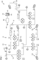
- FIG. 1 shows a water supply network 100, which may be, for example, a municipal supply network for the supply of drinking or service water.
- the water supply network 100 comprises node components 105 and edge components 110, wherein an edge component 110 transports water between two node components 105.
- Exemplary nodal components 105 include a tank 115, a water feeder 120, a water consumer 125, and a water distribution point 130.
- the water feeder 120 also referred to simply as feeder 120, typically includes a well, a source, or a delivery point other water network.
- a volume of water that flows from a feeder 120 into the water supply network 100 per time can usually not be influenced or only between predetermined limits.
- a water consumer 125 typically involves an end user, such as a private household, a commercial facility, or a public tapping point. How much water is withdrawn by the water consumer 125 from the water distribution network 100 can be at least approximately predicted, but an actual withdrawal can always deviate from a prognosis.
- a water distribution point 130 has n ports for edge components 110 and is also called an n-manifold or n-piece, where n is usually ⁇ 2.
- a T-shaped water distribution point 130 may also be called 3-manifold or 3-piece.
- An edge component 110 may be controllable and in particular comprise a valve 135, a pump 140 or a turbine 145, or may not be controllable and may comprise approximately a pipeline 150.
- controllable edge components 110 there are usually those which receive energy depending on their driving, in particular a pump 140, and those which absorb energy only during an adjustment, such as a valve 135, or are completely passive like the conduit 150.
- a pump 140 can only be switchable, so it can either be driven in a first operating configuration so that it operates and consumes energy, or it can not be driven in a second operating configuration so that it does not work and does not consume energy. It can also be a multi-stage or analog controllable in their performance pump 140 may be provided.
- the pump 140 may have more than two operating configurations.
- the performance of the pump can be done by controlling a particular electric drive or, for example, via the control of a coupling element such as a hydrodynamic torque converter.
- Infinitely controllable pumps 140 may also be provided by interval specifications for flow rate and Energy consumption in any number of different operating configurations are modeled and controlled.
- a pump 140 may be powered by a utility 155, which typically includes a connection or transfer point of a utility grid.
- the utility 155 may also include, for example, a local generator or other energy converter.
- a plurality of pumps 140 may be combined in a pumping station 160.
- the pumps 140 may be of a similar design, that is to say with the same pumping direction and pumping capacity, or different pumps 140 may be logically or physically enclosed.
- a turbine 145 operates substantially inversely with a pump 140, thus converting water flow into mechanical or electrical energy.
- Several turbines 145 may be combined in a turbine station 165, which may be formed analogous to a pumping station 160.
- a controller 168 is provided to determine a control plan 170.
- the control device 168 preferably comprises a processing device, which may be designed in particular as a programmable microcomputer.
- the control plan 170 comprises a chronological sequence of activations of at least one controllable edge component 110 of the water supply network 100, in particular an edge component 110, which receives energy as a pump 140 depending on its activation.
- the control plan 170 is preferably a rough planning, ie does not lay down all aspects of Control of the water supply network in advance, but initially creates only a framework on the basis of which a control can be performed depending on current parameters of the water supply network 100, in particular on the basis of actual withdrawals, actual inflows and actual water levels in tanks 115th
- the control plan 170 preferably relates to a predetermined planning horizon 175 that may be divided into individual time slices 180.
- the planning horizon 175 may be, for example one or more days, wherein a timeslice 180 may be, for example, one hour.
- the time slices 180 are preferably the same length and completely fill the planning horizon 175.
- the planning horizon 175 always extends into the future, so that with the advent of a time slice 180, a new time slice 180 can emerge in the farthest future within the planning horizon 175.
- the control plan 170 can only be determined for the newly added timeslice 180 or always for all time slices 180 of the planning horizon 175.
- the water supply network 100 may be controlled based on a particular control plan 170.
- one or more dedicated control devices are provided for this purpose, which may be arranged in particular in a decentralized manner, and to which preferably at least a part of the particular control plan is provided.
- the controller 168 includes an interface 185 for connection to at least one of the controllable edge components 110 and is configured to provide a matching control signal to the edge component 110 via the interface 185.
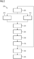
- FIG. 2 shows a flow chart of a method 200 for controlling a water supply network 100, such as that of FIG. 1 .
- Individual steps of the method 200 may be performed in a sequence other than that indicated.
- the method 200 may be executed, in whole or in part, on the controller 168.
- the control device 168 may comprise a programmable microcomputer or microcontroller and the method 200 may be present at least partially in the form of a computer program product with program code means.
- the method 200 is tightly coupled to the controller 168 so that features or benefits may be transferred from the method 200 to the apparatus 168, or vice versa.
- a step 205 the planning horizon 175 and the time slices 180 are preferably determined. This provision may be repeated on subsequent runs of the method 200 or the previously determined result be adopted.
- feed limits of the water feeders 120 are preferably determined.
- an upper and a lower limit can be determined, either for all water feeders 120 or for a group or a single water feed 120.
- withdrawals by water consumers 125 are preferably determined or predicted.
- the prediction can be determined based on historical values or parameters such as an expected temperature or.
- the determinations of steps 210 and 215 are preferably performed for each of the time slices 180.
- an operating configuration preferably comprises the configuration of an edge component 110 of the water supply network 100.
- the configuration may in particular comprise an activation state of a controllable edge component 110 and also an energy absorption of the edge component 110 or a flow through the edge component 110.
- the total of all possible operating configurations of all node components 110 may include Structure or architecture of the water supply network 100 logically reflect.
- energy costs may be determined. These may be dependent on a point in time, so that they can be determined individually for the time slices 180. Optionally, energy costs can also be determined by different providers, so that later a cheaper provider can be selected. The energy cost is relevant to the energy received by, for example, a pump 140 when it is energized to deliver water between node devices 105 of the water service network 100.
- states of node components 105 per time slice may be determined.
- the node components 105 may in particular comprise a tank 105 and the state of the tank may relate to admissibility barriers at its filling or water level, z. B. maximum container volume or minimum level.
- initial states of components of the water supply network 100 may be determined. As a result, an operating state of the water supply network 100 can be reflected.
- the initial states may include, for example, controls of components, positions of valves, or levels of tanks 115.
- Steps 205-230 generally involve determining information necessary for the actual deployment of a control plan 170.
- the steps 205 to 230 can also be carried out in parallel or in any order.
- control plan 170 may be determined.
- the control plan 170 preferably includes all previously determined time slices 180.
- the specific determination of the control plan 170 is preferably carried out as an optimization within a search space which is predetermined by the restrictions described above. The optimization can be carried out in particular by means of a mixed-integer program, as will be explained in more detail below.
- the particular control plan 170 may be provided, for example by being forwarded in parts or completely to a control device for controlling the water supply network 100.
- the control plan 170 may also be output to a person for control or reference, for example in numerical or graphical form.
- control plan 170 in particular in the context of a current time slice 180, can be performed by controlling the water supply network on the basis of the control plan 170.
- the control may be by means of the device 165 or other device.
- a further rough planning can be carried out by repeating the method 200.
- a mathematical notation is used, which is particularly suitable for implementation by means of a mixed integer program, which, for example, with the aid of a commercial solver such.
- B. Scip, CPLEX or Gurobi can be solved in order to obtain optimized as a planning result values for the variables of the model.
- Mixed integer linear programs can be easily extended and adjusted, for example by additional constraints.
- T ⁇ t 1 , t 2 , ..., t n ⁇ set of overlap-free and immediately adjacent time slices into which the planning horizon is divided; the indices correspond to the associated temporal sorting of these time slices, ie t 1 denotes the first time slice, t n the last one.
- V Quantity of node components v in the water network ie, the amount of all tanks, water feeders, water consumers, water distribution points, etc.
- E Amount of edge components e in the water network ie amount of all pumps, valves, piping etc.
- a configuration defines a lower and an upper limit for the permissible flow rates (see parameters introduced below)
- c min Minimum water flow rate (measured, for example, in m 3 / s) by the edge component e in the operating configuration c (negative values indicate a flow of water contrary to the orientation of the edge orientation; ⁇ e . c min consequently not negatively selected) ⁇ e . c Max Maximum water flow rate (measured, for example, in m 3 / s) by the edge component e in the operating configuration c ⁇ e sw Cost rate per circuit of the edge component e ( ⁇ 0 only for pumps) ⁇ e . t s Cost rate per kWh of energy consumed during operation of the edge component e during the time slice t ⁇ e .
- Variables (identifier: Latin lowercase letters) 0 ⁇ d e . t . c 1 ⁇ ⁇ t Variable for the duration (measured in s), in which the edge component e is operated before the potential switching operation of the component in time slice t in the state configuration c ( e ⁇ E, t ⁇ T, c ⁇ C e ) 0 ⁇ d e . t .
- c 1 Variable for the water flow (measured, for example, in m 3 ) by the edge component e before the potential switching operation of the component in time slice t in the operating state configuration c ( e E, t E T, c E C e ) f e . t . c 2
- Variable for the water flow (measured, for example, in m 3 ) by the edge component e after a possible switching operation of the component in time slice t in the operating state configuration c ( e E, t E T, c E C e ) G e . t .
- the energy consumption G e . t . c 1 is with the associated water flow f e . t . c 1 correlated G e . t . c 2 Variable for the energy consumption (measured in kWh) of the edge component e after the potential switching operation of the component in time slice t in the operating state configuration c ( e ⁇ E, t ⁇ T, c ⁇ C e ); the energy consumption G e . t .
- t 1 Variable for water consumption (measured eg in m 3 ) in the node component v before the potential switching time during the time slice t ( v ⁇ V, t ⁇ T ); a negative value for u v . t 1 thus corresponds de facto to a water feed.
- u v . t 2 Variable for the water consumption (measured eg in m 3 ) in the node component v after the potential switching time during the time slice t ( v ⁇ V, t ⁇ T ); a negative value for u v . t 2 thus corresponds de facto to a water feed.
- t end Variable for the stored volume of water (measured, for example, in m 3 ) in the node component v at the end of the time slice t ( v ⁇ V , t ⁇ T ) w v . t s Variable for the stored water volume (measured eg in m 3 ) in the node component v at the time of the potential switching time point during the time slice t ( v ⁇ V, t ⁇ T )
- Secondary condition (1) defines for all end times of the time slices t a lower and an upper bound for the amount of water stored in the node component v .
- Condition (1) ensures that only in tanks can water actually be stored.
- a lower barrier usually corresponds to a minimum or safety level and an upper bound of physical capacity.
- Secondary condition (2) analogously to (1) defines for all potential switching times of the edge components within all time slices t a lower and an upper limit for the amount of water stored in the node component v . These barriers correspond in our model without limitation of generality to those for the end times. ⁇ v . t min ⁇ s t ⁇ u v . t 1 ⁇ ⁇ v . t Max ⁇ s t v ⁇ V . t ⁇ T
- Secondary condition (3) defines for all time slices t and all node components v a lower and an upper bound for the water consumption averaged from the time step start to the potential switching time of the edge components in this node.
- the water consumption is measured on the basis of a product of rate and duration, for example in cubic meters.
- the water consumption can be fixed to zero by the parameter specifications.
- the upper and lower bounds can be fixed to the respective predicted water consumption rates in the respective time step. Only with the feeders can thus result in real interval conditions that reflect the minimum and maximum water output of a water source.
- Secondary condition (4) analogously to (3) defines for all time slices t and all node components v a lower and an upper bound for the water consumption averaged from the potential switching time of the edge components up to the time step end in this node.
- Secondary condition (5) defines for all time slices t , each edge component e and each associated operating configuration c a lower and upper bound for the respective water flow averaged by e from the time step beginning to the potential switching time of the edge components within the time step.
- the water flow is measured on the basis of a product of rate and duration, for example in cubic meters.
- pumps z. B. off operating state "pump off"
- the flow for this configuration using the barrier parameters is preferably fixed to zero.
- Secondary condition (7) describes the water balance equation for all node components v from the start of the planning horizon (first time step) to the first potential switching time, which is usually within the first time slice.
- the volume of water stored in v at this first potential switching instant results from the initial volume ⁇ v ini . up to this point in time, and by the water consumption of the node and the flow rates through the outgoing v out edge components until this time is reduced by the flow rates through the incoming edge components in v .
- the water consumption can also be negative, for example, in a feeder. The same may also apply to the flow of water through the edge components.
- the respective Sign ensures that the associated amounts of water contribute correctly to the water balance equation.
- the secondary conditions (10), (13) and (5) can ensure that, when summing over all operating states, there can only be at most one non-zero summand, since each edge component can only be in a single operating state by the first switching time.
- w v . t end w v . t s - u v . t 2 + ⁇ e ⁇ e v + ⁇ e ⁇ C e f e . t . c 2 - ⁇ e ⁇ e v - ⁇ e ⁇ C e f e . t . c 2 v ⁇ V . t ⁇ T
- Secondary condition (8) has the same balancing logic as constraint (7). However, it describes for all node components v and all time slices t the transition of the volume of water stored in v from the time of the potential switching time within the time slice to the end of the associated time slice.
- w v . t s w v . ⁇ t - 1 end - u v . t 1 + ⁇ e ⁇ e v + ⁇ e ⁇ C e f e . t . c 1 - ⁇ e ⁇ e v - ⁇ e ⁇ C e f e . t . c 1 v ⁇ V . t ⁇ T ⁇ t 1
- variables k e . t . c 1 are binary variables that can only take the value 0 or 1, constraint (11) implies that there must always be exactly one clearly defined operating configuration c for each edge component e , from the respective beginning of a time slice t to the associated potential switching time within the time slice is active. All other possible operating configurations of the edge component e thus remain inactive during this period.
- ⁇ c ⁇ C e k e . t . c 2 1 e ⁇ e . t ⁇ T
- Secondary condition (12) is analogous to secondary condition (11), but deals with the time period from the potential switching time to the end of the respective time slice. Together with (11), (12) thus implies that in each time slice at most two operating configurations can be active, one each before and one after the potential switching time. If this is the same configuration, it can not effectively be switched and there is only one active configuration in that time slice. d e . t . c 1 ⁇ ⁇ t ⁇ k e . t . c 1 e ⁇ e . t ⁇ T . c ⁇ C e
- Secondary condition (14) is formulated analogously to secondary condition (13) and treats the respective second portion of each time slice t , that is to say from the potential switching time point to the end of the time slice.
- ⁇ c ⁇ C e d e . t . c 1 + d e . t . c 2 ⁇ t e ⁇ e . t ⁇ T
- Secondary condition (16) serves to determine the potential switching time for each time slice t . Because of (10) and (13), only a single one of the summands can be unequal to zero.
- the duration associated with this summation for the active time of the corresponding operating configuration corresponds to the switching time within the time slice, measured since the start of the time slice.
- the constraints (17) and (18) in combination represent a lower bound for the number of circuits within a time slice, ie, it is checked whether the edge component e at the potential switching time within the time slice t actually a circuit took place or not. If there was no circuit, then the variables have k e . t . c 1 and k e . t . c 2 For all operating configurations, c has the same value and the lower limit has the value 0. However, if a circuit was used, the values differ for the variables k e . t . c 1 and k e . t . c 2 exactly for the two active operating configurations.
- the values of the variables m e, t in the calculated solution are preferably always chosen to be minimal, ie identical to the associated lower limit.
- the variables m e, t in the optimal solution always assume the value 0 or the value 1, without being explicitly declared as binary.
- the constraint pair (19) and (20) have the same logic as the constraint pair (17) and (18). The difference lies in the fact that not the circuits within the time slices are checked, but the transition from the predecessor time slice to its successor time slice. Since an immediate switching of the initial operating configuration at time 0 is usually not provided (at most as a circuit "within" the time slice), the first time slice in the constraints (19) and (20) is respectively excluded.
- Secondary condition (21) defines for each time slice t the energy consumption up to the potential switching time associated with the operation of the edge component e in the operating configuration c , if c prescribes a unique operating point, in particular with regard to a flow rate and thus also with respect to a performance. This is calculated from the product of the service belonging to c and the activity duration of this operating configuration. It should also be noted that the time unit must be converted from seconds to hours to indicate the energy in kWh.
- G e . t . c 1 ⁇ e . c min ⁇ d e . t . c 1 + ⁇ e . c Max - ⁇ e . c min ⁇ e . c Max - ⁇ e .
- Secondary condition (22) defines for each time slice t the energy consumption up to the potential switching time associated with the operation of the edge component e in the operating configuration c , if c instead of a unique operating point a true interval of possible operating points, in particular with respect to a flow rate and thus also with regard to a service.
- Secondary condition (23) is the analogue to secondary condition (21) for the period from the potential switching time to the end of the associated time slice t .
- G e . t . c 2 ⁇ e . c min ⁇ d e . t . c 2 + ⁇ e . c Max - ⁇ e . c min ⁇ e . c Max - ⁇ e . c min ⁇ f e . t . c 2 - ⁇ e . c min ⁇ d e . t . c 2 ⁇ ⁇ 1 3600 ⁇ H s e ⁇ e . t ⁇ T . c ⁇ C e : ⁇ e . c min ⁇ ⁇ e . c Max
- Secondary condition (24) is the analog of constraint (22) for the period from the potential switching time to the end of the associated time slice t .
- the objective function is based on a cost function that is to be minimized. ⁇ e ⁇ e ⁇ e sw ⁇ ⁇ t ⁇ T m e . t + ⁇ t ⁇ T ⁇ t 1 n e . t
- Formula (25) describes the costs associated with the circuits of all edge components e .
- the number of all circuits determined with the variables m e, t and n e, t with the associated cost set ⁇ e sw multiplied and then formed the sum over all edge components.
- ⁇ e sw 0 for all edge components that are not pumps or turbines.
- Formula (26) describes the energy costs resulting from the operating strategy of the edge components.
- the energy consumption of each edge component e in each possible operating configuration c and in each time step t is calculated (this corresponds G e . t . c 1 + G e . t . c 2 ) and then with the corresponding one Energy cost rate ⁇ e . t s multiplied. Subsequently, the sum over all individual costs in the respective time steps and for all edge components is formed in order to obtain the total energy costs.
- a concrete operating configuration of the edge components can also be summarized in a condition class.
- condition class "exactly one pump is active” could be introduced, in which the three concrete operating configurations "only pump A is on”, “only pump B is on” and " only pump C is to be summarized. This can also be very helpful in the definition of the technically meaningful combinations of operating configurations of the edge components for the reduction of the combinatorics.
- a fixation or partial fixation In some scheduling instances, it may be desirable not to give the optimizer full discretion over certain aspects of the solution. Instead, it may be desirable to predetermine some decisions already by a fixation or partial fixation.
- An example of this would be a maintenance of a pumping station, where all pumps must be switched off. In this case, the maintenance can be placed on one or more corresponding time slices and there operating configurations of all pumps can be predefined on "pump off". The same can be done for the condition classes described above. For example, it could simply be required for a pumping station that the status class "all pumps off" must be active in the time slices belonging to the maintenance. The associated state fixes or state fixes can then be given to the optimizer as additional constraints, so that these specifications must be taken into account in the optimization.
- the water consumption in the node components can be evaluated by means of a cost function and integrated into the target function, so that the costs associated with the flow of water are also included in the optimization.
- This requires on the input side of data corresponding cost rates for water per volume at the different feeders. It also time series can be supported if the prices are not constant in time.
- the total capacity for the water delivery of feeders which is valid in the considered planning horizon, can also be modeled and included in the optimization, for B. by the specification of a maximum daily total delivery.
- the energy required to operate the pumps is assumed to be unlimited.
- upper limits for energy consumption can also be integrated into the model.
- the presented model is a possibility for the rough planning of the water supply network or its control. Nevertheless, other physical conditions can be integrated into this model, the absence of which could otherwise lead to unrealistic planning results.
- An example of this are tanks that are connected to each other exclusively via pipes. In this case, additional conditions may be introduced to ensure that the level of these tanks must always be at the same level above sea level.
- the described mathematical model includes many upper and lower bounds that set the value ranges for the variables. It is therefore easy to create instances which do not have an acceptable solution because the chosen barriers do not match. In this case, so-called soft constraints can be made of the hard, ie unchangeable constraints by allowing a violation of the barriers, but this excess is charged at very high cost in the objective function. In this way it is possible, when planning a water supply network, a subnetwork or a component, to obtain a statement about which manipulated variables should be rotated in order, in the case of an inadmissible instance, to adapt to an operational system with as few adaptations as possible. To get architecture.
Priority Applications (3)
| Application Number | Priority Date | Filing Date | Title |
|---|---|---|---|
| EP17188473.7A EP3450638A1 (fr) | 2017-08-30 | 2017-08-30 | Commande d'un réseau de distribution d'eau |
| US16/109,850 US10782663B2 (en) | 2017-08-30 | 2018-08-23 | Control of a water supply network |
| CN201811004609.0A CN109426923B (zh) | 2017-08-30 | 2018-08-30 | 供水网络的控制 |
Applications Claiming Priority (1)
| Application Number | Priority Date | Filing Date | Title |
|---|---|---|---|
| EP17188473.7A EP3450638A1 (fr) | 2017-08-30 | 2017-08-30 | Commande d'un réseau de distribution d'eau |
Publications (1)
| Publication Number | Publication Date |
|---|---|
| EP3450638A1 true EP3450638A1 (fr) | 2019-03-06 |
Family
ID=59846327
Family Applications (1)
| Application Number | Title | Priority Date | Filing Date |
|---|---|---|---|
| EP17188473.7A Ceased EP3450638A1 (fr) | 2017-08-30 | 2017-08-30 | Commande d'un réseau de distribution d'eau |
Country Status (3)
| Country | Link |
|---|---|
| US (1) | US10782663B2 (fr) |
| EP (1) | EP3450638A1 (fr) |
| CN (1) | CN109426923B (fr) |
Cited By (2)
| Publication number | Priority date | Publication date | Assignee | Title |
|---|---|---|---|---|
| WO2020192944A1 (fr) | 2019-03-28 | 2020-10-01 | Siemens Aktiengesellschaft | Procédé et dispositif de commande d'un réseau d'adduction d'eau |
| CN113449993A (zh) * | 2021-06-29 | 2021-09-28 | 中国水利水电科学研究院 | 一种城市水源供水调度方法 |
Families Citing this family (3)
| Publication number | Priority date | Publication date | Assignee | Title |
|---|---|---|---|---|
| CN113780972B (zh) * | 2021-08-04 | 2022-08-02 | 广州云硕科技发展有限公司 | 一种智慧园区的一体化管理方法及系统 |
| CN115017666B (zh) * | 2022-08-08 | 2022-11-01 | 廊坊市清泉供水有限责任公司 | 地下水源地智能化运行方法及系统 |
| CN116720712B (zh) * | 2023-08-07 | 2023-12-29 | 泰能天然气有限公司 | 一种燃气应急调度数据管理系统 |
Citations (2)
| Publication number | Priority date | Publication date | Assignee | Title |
|---|---|---|---|---|
| US20070130093A1 (en) * | 2005-12-07 | 2007-06-07 | Alireza Haji-Valizadeh | Utility management system and method |
| US20170090440A1 (en) * | 2015-09-29 | 2017-03-30 | International Business Machines Corporation | Multi-objective scheduling for on/off equipment |
Family Cites Families (5)
| Publication number | Priority date | Publication date | Assignee | Title |
|---|---|---|---|---|
| US4674279A (en) * | 1984-09-12 | 1987-06-23 | Acres International Corporation | Control system for run-of-river hydroelectric plant |
| WO2009020402A1 (fr) | 2007-08-03 | 2009-02-12 | Derceto Limited | Distribution d'eau |
| AU2009315897B2 (en) * | 2008-11-14 | 2014-03-13 | Abb Schweiz Ag | System and method for optimized decision-making in water supply networks and/or water supply operations |
| CN102629106B (zh) * | 2012-04-11 | 2014-10-08 | 广州东芝白云自动化系统有限公司 | 供水控制方法及系统 |
| US20170159270A1 (en) * | 2014-07-21 | 2017-06-08 | Neotech Systems Pvt. Ltd. | Method for monitoring, communicating and controlling water consumption and availability and system thereof |
-
2017
- 2017-08-30 EP EP17188473.7A patent/EP3450638A1/fr not_active Ceased
-
2018
- 2018-08-23 US US16/109,850 patent/US10782663B2/en active Active
- 2018-08-30 CN CN201811004609.0A patent/CN109426923B/zh active Active
Patent Citations (2)
| Publication number | Priority date | Publication date | Assignee | Title |
|---|---|---|---|---|
| US20070130093A1 (en) * | 2005-12-07 | 2007-06-07 | Alireza Haji-Valizadeh | Utility management system and method |
| US20170090440A1 (en) * | 2015-09-29 | 2017-03-30 | International Business Machines Corporation | Multi-objective scheduling for on/off equipment |
Non-Patent Citations (1)
| Title |
|---|
| BENE JÓZSEF GERGELY: "Pump Schedule Optimisation Techniques For Water Distribution Systems", ACTA UNIVERSITATIS OULUENSIS TECHNICA C 472, 18 November 2013 (2013-11-18), http://jultika.oulu.fi/Record/isbn978-952-62-0266-2, XP055415987, ISBN: 978-952-6202-66-2, Retrieved from the Internet <URL:http://jultika.oulu.fi/files/isbn9789526202662.pdf> [retrieved on 20171016] * |
Cited By (2)
| Publication number | Priority date | Publication date | Assignee | Title |
|---|---|---|---|---|
| WO2020192944A1 (fr) | 2019-03-28 | 2020-10-01 | Siemens Aktiengesellschaft | Procédé et dispositif de commande d'un réseau d'adduction d'eau |
| CN113449993A (zh) * | 2021-06-29 | 2021-09-28 | 中国水利水电科学研究院 | 一种城市水源供水调度方法 |
Also Published As
| Publication number | Publication date |
|---|---|
| CN109426923A (zh) | 2019-03-05 |
| US10782663B2 (en) | 2020-09-22 |
| US20190064761A1 (en) | 2019-02-28 |
| CN109426923B (zh) | 2022-11-29 |
Similar Documents
| Publication | Publication Date | Title |
|---|---|---|
| EP3450638A1 (fr) | Commande d'un réseau de distribution d'eau | |
| EP1748529B1 (fr) | Procédé et système pour le pronostic des quantités d'énergie demandées par un consommateur, en particulier un consommateur industriel, à un producteur ou fournisseur d'énergie, et dispositif pour le pronostic de ces besoins en énergie | |
| WO2011092012A2 (fr) | Installation et procédé d'optimisation du mode de fonctionnement d'un réseau de distribution | |
| DE112013007295T5 (de) | Elektroleistungssystem-Steuervorrichtung, Elektroleistungssystem und Elektroleistungssystem-Steuerverfahren | |
| DE102007018313A1 (de) | Optimierendes Steuerverfahren und Steuersystem, Gesamt-Steuervorrichtung und lokale Steuervorrichtung | |
| WO2013124302A2 (fr) | Système de fourniture de chaleur et procédé permettant de faire fonctionner ledit système | |
| DE102015101738A1 (de) | Verfahren zum Betrieb einer Energieerzeugungsanlage und Energieerzeugungsanlage | |
| DE102017205968A1 (de) | Verfahren zum Koordinieren eines Leistungsaustauschs zwischen einer Vielzahl von technischen Kleineinheiten und einem elektrischen Übertragungsnetz | |
| DE102018221156A1 (de) | Vorrichtung und Verfahren zur Steuerung von Energieflüssen zwischen Komponenten eines Energiesystems | |
| EP3635651B1 (fr) | Procédé pour faire fonctionner une pluralité d'unités techniques en tant qu'ensemble sur un réseau de distribution électrique, ainsi que dispositif de commande et dispositif électrique | |
| WO2010057516A1 (fr) | Procédé de détermination de flux de charge électrique dans un réseau d'alimentation en énergie électrique | |
| EP4012871B1 (fr) | Procédé de transfert dirigé de l'énergie sous forme de paquets énergie | |
| EP3664243B1 (fr) | Planification de fonctionnement prédictive dans un micro-réseau en fonction des fenêtres temporelles de charge élevé d'un réseau électrique principal | |
| EP1764562A1 (fr) | Procédé d'exploitation d'une cellule de combustion dans un système de chauffage | |
| EP4047533A1 (fr) | Procédé de génération automatique d'une feuille de route non cyclique | |
| DE102013208744A1 (de) | Verfahren zum automatischen Ermitteln des Energiebedarfs und/oder des Belegungsbedarfs einer Elektrotankstelle und zugehörige DV-Anlagen | |
| DE102014010019B4 (de) | Verfahren zum Schalten von dezentralen Energiewandlern | |
| EP3267039B1 (fr) | Procédé et système de réglage d'une installation de pompage | |
| WO2019096424A1 (fr) | Commande de micro-réseaux | |
| EP3101749B1 (fr) | Procédé de commande d'un consommateur de courant local | |
| EP3311460B1 (fr) | Système distribué de conversion d'énergie | |
| DE19510343A1 (de) | Verfahren zur sequentiellen Vorsteuerung eines Prozesses | |
| DE102016000117B4 (de) | Verfahren zur Sicherung der Energiestabilität in einem HGÜ-Netz | |
| DE102009008033B3 (de) | Versorgung von energietechnischen Objekten mit Energie verschiedener Energiearten | |
| CH708504A1 (de) | Verfahren zur Bestimmung einer optimalen Betriebsweise und zum Betrieb eines Portfolios technischer Anlagen. |
Legal Events
| Date | Code | Title | Description |
|---|---|---|---|
| PUAI | Public reference made under article 153(3) epc to a published international application that has entered the european phase |
Free format text: ORIGINAL CODE: 0009012 |
|
| STAA | Information on the status of an ep patent application or granted ep patent |
Free format text: STATUS: THE APPLICATION HAS BEEN PUBLISHED |
|
| AK | Designated contracting states |
Kind code of ref document: A1 Designated state(s): AL AT BE BG CH CY CZ DE DK EE ES FI FR GB GR HR HU IE IS IT LI LT LU LV MC MK MT NL NO PL PT RO RS SE SI SK SM TR |
|
| AX | Request for extension of the european patent |
Extension state: BA ME |
|
| STAA | Information on the status of an ep patent application or granted ep patent |
Free format text: STATUS: REQUEST FOR EXAMINATION WAS MADE |
|
| 17P | Request for examination filed |
Effective date: 20190319 |
|
| RBV | Designated contracting states (corrected) |
Designated state(s): AL AT BE BG CH CY CZ DE DK EE ES FI FR GB GR HR HU IE IS IT LI LT LU LV MC MK MT NL NO PL PT RO RS SE SI SK SM TR |
|
| STAA | Information on the status of an ep patent application or granted ep patent |
Free format text: STATUS: EXAMINATION IS IN PROGRESS |
|
| 17Q | First examination report despatched |
Effective date: 20200204 |
|
| STAA | Information on the status of an ep patent application or granted ep patent |
Free format text: STATUS: EXAMINATION IS IN PROGRESS |
|
| STAA | Information on the status of an ep patent application or granted ep patent |
Free format text: STATUS: THE APPLICATION HAS BEEN REFUSED |
|
| 18R | Application refused |
Effective date: 20210723 |