EP3311460B1 - Système distribué de conversion d'énergie - Google Patents
Système distribué de conversion d'énergie Download PDFInfo
- Publication number
- EP3311460B1 EP3311460B1 EP16731092.9A EP16731092A EP3311460B1 EP 3311460 B1 EP3311460 B1 EP 3311460B1 EP 16731092 A EP16731092 A EP 16731092A EP 3311460 B1 EP3311460 B1 EP 3311460B1
- Authority
- EP
- European Patent Office
- Prior art keywords
- energy
- ewe
- energy conversion
- entity
- evaluation
- Prior art date
- Legal status (The legal status is an assumption and is not a legal conclusion. Google has not performed a legal analysis and makes no representation as to the accuracy of the status listed.)
- Active
Links
- 238000006243 chemical reaction Methods 0.000 title claims description 118
- 238000011156 evaluation Methods 0.000 claims description 96
- 238000000034 method Methods 0.000 claims description 70
- 230000008569 process Effects 0.000 claims description 48
- 238000003860 storage Methods 0.000 claims description 28
- 230000002776 aggregation Effects 0.000 claims description 25
- 238000004220 aggregation Methods 0.000 claims description 25
- 238000004891 communication Methods 0.000 claims description 15
- 239000000969 carrier Substances 0.000 claims description 7
- 238000005265 energy consumption Methods 0.000 claims description 4
- 230000007613 environmental effect Effects 0.000 claims description 4
- 239000003344 environmental pollutant Substances 0.000 claims description 2
- 238000004519 manufacturing process Methods 0.000 claims description 2
- 231100000719 pollutant Toxicity 0.000 claims description 2
- 238000013459 approach Methods 0.000 description 37
- 238000005457 optimization Methods 0.000 description 14
- 230000001419 dependent effect Effects 0.000 description 13
- 230000006870 function Effects 0.000 description 13
- 239000007789 gas Substances 0.000 description 11
- 239000003795 chemical substances by application Substances 0.000 description 10
- 238000004364 calculation method Methods 0.000 description 9
- 238000013209 evaluation strategy Methods 0.000 description 9
- 230000005611 electricity Effects 0.000 description 8
- 230000003068 static effect Effects 0.000 description 8
- 238000009826 distribution Methods 0.000 description 6
- 238000012854 evaluation process Methods 0.000 description 6
- 238000013439 planning Methods 0.000 description 6
- 230000002123 temporal effect Effects 0.000 description 6
- 230000008859 change Effects 0.000 description 5
- 238000011161 development Methods 0.000 description 5
- 230000018109 developmental process Effects 0.000 description 5
- 238000007726 management method Methods 0.000 description 5
- 238000005406 washing Methods 0.000 description 5
- 230000004931 aggregating effect Effects 0.000 description 4
- 230000006399 behavior Effects 0.000 description 4
- 238000013499 data model Methods 0.000 description 4
- 238000005516 engineering process Methods 0.000 description 4
- 238000010438 heat treatment Methods 0.000 description 4
- 230000036961 partial effect Effects 0.000 description 4
- 230000003044 adaptive effect Effects 0.000 description 3
- 230000033228 biological regulation Effects 0.000 description 3
- 238000005259 measurement Methods 0.000 description 3
- 238000002360 preparation method Methods 0.000 description 3
- 238000012545 processing Methods 0.000 description 3
- 230000006641 stabilisation Effects 0.000 description 3
- 238000011105 stabilization Methods 0.000 description 3
- 230000009897 systematic effect Effects 0.000 description 3
- 230000036962 time dependent Effects 0.000 description 3
- 238000012546 transfer Methods 0.000 description 3
- 230000007704 transition Effects 0.000 description 3
- CURLTUGMZLYLDI-UHFFFAOYSA-N Carbon dioxide Chemical compound O=C=O CURLTUGMZLYLDI-UHFFFAOYSA-N 0.000 description 2
- 230000009471 action Effects 0.000 description 2
- 230000005540 biological transmission Effects 0.000 description 2
- 238000013461 design Methods 0.000 description 2
- 230000004069 differentiation Effects 0.000 description 2
- 238000005538 encapsulation Methods 0.000 description 2
- 238000012423 maintenance Methods 0.000 description 2
- 238000013507 mapping Methods 0.000 description 2
- VNWKTOKETHGBQD-UHFFFAOYSA-N methane Chemical compound C VNWKTOKETHGBQD-UHFFFAOYSA-N 0.000 description 2
- 238000012544 monitoring process Methods 0.000 description 2
- 230000002829 reductive effect Effects 0.000 description 2
- 230000004044 response Effects 0.000 description 2
- 230000007306 turnover Effects 0.000 description 2
- 238000011144 upstream manufacturing Methods 0.000 description 2
- 241001136792 Alle Species 0.000 description 1
- 238000011511 automated evaluation Methods 0.000 description 1
- 229910002092 carbon dioxide Inorganic materials 0.000 description 1
- 239000001569 carbon dioxide Substances 0.000 description 1
- 238000002485 combustion reaction Methods 0.000 description 1
- 238000005094 computer simulation Methods 0.000 description 1
- 230000001186 cumulative effect Effects 0.000 description 1
- 230000007423 decrease Effects 0.000 description 1
- 238000001035 drying Methods 0.000 description 1
- 238000004146 energy storage Methods 0.000 description 1
- 238000003912 environmental pollution Methods 0.000 description 1
- 238000000605 extraction Methods 0.000 description 1
- 238000001914 filtration Methods 0.000 description 1
- 230000036541 health Effects 0.000 description 1
- 238000009434 installation Methods 0.000 description 1
- 230000003993 interaction Effects 0.000 description 1
- 238000012432 intermediate storage Methods 0.000 description 1
- 230000004807 localization Effects 0.000 description 1
- 230000007774 longterm Effects 0.000 description 1
- 238000010327 methods by industry Methods 0.000 description 1
- 239000003345 natural gas Substances 0.000 description 1
- 238000004393 prognosis Methods 0.000 description 1
- 238000011158 quantitative evaluation Methods 0.000 description 1
- 230000009467 reduction Effects 0.000 description 1
- 230000003252 repetitive effect Effects 0.000 description 1
- 230000000717 retained effect Effects 0.000 description 1
- 238000000926 separation method Methods 0.000 description 1
- 238000004088 simulation Methods 0.000 description 1
- 239000000344 soap Substances 0.000 description 1
- 210000002023 somite Anatomy 0.000 description 1
- 230000000087 stabilizing effect Effects 0.000 description 1
- 238000012144 step-by-step procedure Methods 0.000 description 1
- 230000009885 systemic effect Effects 0.000 description 1
- 238000012384 transportation and delivery Methods 0.000 description 1
- 239000002918 waste heat Substances 0.000 description 1
- 238000005303 weighing Methods 0.000 description 1
Images

Classifications
-
- H—ELECTRICITY
- H02—GENERATION; CONVERSION OR DISTRIBUTION OF ELECTRIC POWER
- H02J—CIRCUIT ARRANGEMENTS OR SYSTEMS FOR SUPPLYING OR DISTRIBUTING ELECTRIC POWER; SYSTEMS FOR STORING ELECTRIC ENERGY
- H02J3/00—Circuit arrangements for ac mains or ac distribution networks
- H02J3/38—Arrangements for parallely feeding a single network by two or more generators, converters or transformers
- H02J3/381—Dispersed generators
-
- H—ELECTRICITY
- H02—GENERATION; CONVERSION OR DISTRIBUTION OF ELECTRIC POWER
- H02J—CIRCUIT ARRANGEMENTS OR SYSTEMS FOR SUPPLYING OR DISTRIBUTING ELECTRIC POWER; SYSTEMS FOR STORING ELECTRIC ENERGY
- H02J3/00—Circuit arrangements for ac mains or ac distribution networks
- H02J3/003—Load forecast, e.g. methods or systems for forecasting future load demand
-
- H—ELECTRICITY
- H02—GENERATION; CONVERSION OR DISTRIBUTION OF ELECTRIC POWER
- H02J—CIRCUIT ARRANGEMENTS OR SYSTEMS FOR SUPPLYING OR DISTRIBUTING ELECTRIC POWER; SYSTEMS FOR STORING ELECTRIC ENERGY
- H02J3/00—Circuit arrangements for ac mains or ac distribution networks
- H02J3/12—Circuit arrangements for ac mains or ac distribution networks for adjusting voltage in ac networks by changing a characteristic of the network load
- H02J3/14—Circuit arrangements for ac mains or ac distribution networks for adjusting voltage in ac networks by changing a characteristic of the network load by switching loads on to, or off from, network, e.g. progressively balanced loading
-
- H—ELECTRICITY
- H02—GENERATION; CONVERSION OR DISTRIBUTION OF ELECTRIC POWER
- H02J—CIRCUIT ARRANGEMENTS OR SYSTEMS FOR SUPPLYING OR DISTRIBUTING ELECTRIC POWER; SYSTEMS FOR STORING ELECTRIC ENERGY
- H02J3/00—Circuit arrangements for ac mains or ac distribution networks
- H02J3/28—Arrangements for balancing of the load in a network by storage of energy
- H02J3/32—Arrangements for balancing of the load in a network by storage of energy using batteries with converting means
-
- H—ELECTRICITY
- H02—GENERATION; CONVERSION OR DISTRIBUTION OF ELECTRIC POWER
- H02J—CIRCUIT ARRANGEMENTS OR SYSTEMS FOR SUPPLYING OR DISTRIBUTING ELECTRIC POWER; SYSTEMS FOR STORING ELECTRIC ENERGY
- H02J2300/00—Systems for supplying or distributing electric power characterised by decentralized, dispersed, or local generation
- H02J2300/10—The dispersed energy generation being of fossil origin, e.g. diesel generators
-
- H—ELECTRICITY
- H02—GENERATION; CONVERSION OR DISTRIBUTION OF ELECTRIC POWER
- H02J—CIRCUIT ARRANGEMENTS OR SYSTEMS FOR SUPPLYING OR DISTRIBUTING ELECTRIC POWER; SYSTEMS FOR STORING ELECTRIC ENERGY
- H02J2310/00—The network for supplying or distributing electric power characterised by its spatial reach or by the load
- H02J2310/10—The network having a local or delimited stationary reach
- H02J2310/12—The local stationary network supplying a household or a building
- H02J2310/14—The load or loads being home appliances
-
- H—ELECTRICITY
- H02—GENERATION; CONVERSION OR DISTRIBUTION OF ELECTRIC POWER
- H02J—CIRCUIT ARRANGEMENTS OR SYSTEMS FOR SUPPLYING OR DISTRIBUTING ELECTRIC POWER; SYSTEMS FOR STORING ELECTRIC ENERGY
- H02J2310/00—The network for supplying or distributing electric power characterised by its spatial reach or by the load
- H02J2310/50—The network for supplying or distributing electric power characterised by its spatial reach or by the load for selectively controlling the operation of the loads
- H02J2310/56—The network for supplying or distributing electric power characterised by its spatial reach or by the load for selectively controlling the operation of the loads characterised by the condition upon which the selective controlling is based
- H02J2310/62—The condition being non-electrical, e.g. temperature
- H02J2310/64—The condition being economic, e.g. tariff based load management
-
- H—ELECTRICITY
- H02—GENERATION; CONVERSION OR DISTRIBUTION OF ELECTRIC POWER
- H02J—CIRCUIT ARRANGEMENTS OR SYSTEMS FOR SUPPLYING OR DISTRIBUTING ELECTRIC POWER; SYSTEMS FOR STORING ELECTRIC ENERGY
- H02J3/00—Circuit arrangements for ac mains or ac distribution networks
- H02J3/28—Arrangements for balancing of the load in a network by storage of energy
- H02J3/32—Arrangements for balancing of the load in a network by storage of energy using batteries with converting means
- H02J3/322—Arrangements for balancing of the load in a network by storage of energy using batteries with converting means the battery being on-board an electric or hybrid vehicle, e.g. vehicle to grid arrangements [V2G], power aggregation, use of the battery for network load balancing, coordinated or cooperative battery charging
-
- Y—GENERAL TAGGING OF NEW TECHNOLOGICAL DEVELOPMENTS; GENERAL TAGGING OF CROSS-SECTIONAL TECHNOLOGIES SPANNING OVER SEVERAL SECTIONS OF THE IPC; TECHNICAL SUBJECTS COVERED BY FORMER USPC CROSS-REFERENCE ART COLLECTIONS [XRACs] AND DIGESTS
- Y02—TECHNOLOGIES OR APPLICATIONS FOR MITIGATION OR ADAPTATION AGAINST CLIMATE CHANGE
- Y02B—CLIMATE CHANGE MITIGATION TECHNOLOGIES RELATED TO BUILDINGS, e.g. HOUSING, HOUSE APPLIANCES OR RELATED END-USER APPLICATIONS
- Y02B70/00—Technologies for an efficient end-user side electric power management and consumption
- Y02B70/30—Systems integrating technologies related to power network operation and communication or information technologies for improving the carbon footprint of the management of residential or tertiary loads, i.e. smart grids as climate change mitigation technology in the buildings sector, including also the last stages of power distribution and the control, monitoring or operating management systems at local level
- Y02B70/3225—Demand response systems, e.g. load shedding, peak shaving
-
- Y—GENERAL TAGGING OF NEW TECHNOLOGICAL DEVELOPMENTS; GENERAL TAGGING OF CROSS-SECTIONAL TECHNOLOGIES SPANNING OVER SEVERAL SECTIONS OF THE IPC; TECHNICAL SUBJECTS COVERED BY FORMER USPC CROSS-REFERENCE ART COLLECTIONS [XRACs] AND DIGESTS
- Y04—INFORMATION OR COMMUNICATION TECHNOLOGIES HAVING AN IMPACT ON OTHER TECHNOLOGY AREAS
- Y04S—SYSTEMS INTEGRATING TECHNOLOGIES RELATED TO POWER NETWORK OPERATION, COMMUNICATION OR INFORMATION TECHNOLOGIES FOR IMPROVING THE ELECTRICAL POWER GENERATION, TRANSMISSION, DISTRIBUTION, MANAGEMENT OR USAGE, i.e. SMART GRIDS
- Y04S20/00—Management or operation of end-user stationary applications or the last stages of power distribution; Controlling, monitoring or operating thereof
- Y04S20/20—End-user application control systems
- Y04S20/222—Demand response systems, e.g. load shedding, peak shaving
-
- Y—GENERAL TAGGING OF NEW TECHNOLOGICAL DEVELOPMENTS; GENERAL TAGGING OF CROSS-SECTIONAL TECHNOLOGIES SPANNING OVER SEVERAL SECTIONS OF THE IPC; TECHNICAL SUBJECTS COVERED BY FORMER USPC CROSS-REFERENCE ART COLLECTIONS [XRACs] AND DIGESTS
- Y04—INFORMATION OR COMMUNICATION TECHNOLOGIES HAVING AN IMPACT ON OTHER TECHNOLOGY AREAS
- Y04S—SYSTEMS INTEGRATING TECHNOLOGIES RELATED TO POWER NETWORK OPERATION, COMMUNICATION OR INFORMATION TECHNOLOGIES FOR IMPROVING THE ELECTRICAL POWER GENERATION, TRANSMISSION, DISTRIBUTION, MANAGEMENT OR USAGE, i.e. SMART GRIDS
- Y04S20/00—Management or operation of end-user stationary applications or the last stages of power distribution; Controlling, monitoring or operating thereof
- Y04S20/20—End-user application control systems
- Y04S20/242—Home appliances
-
- Y—GENERAL TAGGING OF NEW TECHNOLOGICAL DEVELOPMENTS; GENERAL TAGGING OF CROSS-SECTIONAL TECHNOLOGIES SPANNING OVER SEVERAL SECTIONS OF THE IPC; TECHNICAL SUBJECTS COVERED BY FORMER USPC CROSS-REFERENCE ART COLLECTIONS [XRACs] AND DIGESTS
- Y04—INFORMATION OR COMMUNICATION TECHNOLOGIES HAVING AN IMPACT ON OTHER TECHNOLOGY AREAS
- Y04S—SYSTEMS INTEGRATING TECHNOLOGIES RELATED TO POWER NETWORK OPERATION, COMMUNICATION OR INFORMATION TECHNOLOGIES FOR IMPROVING THE ELECTRICAL POWER GENERATION, TRANSMISSION, DISTRIBUTION, MANAGEMENT OR USAGE, i.e. SMART GRIDS
- Y04S50/00—Market activities related to the operation of systems integrating technologies related to power network operation or related to communication or information technologies
- Y04S50/10—Energy trading, including energy flowing from end-user application to grid
Definitions
- the invention relates to a distributed energy conversion system.
- the main focus of the control tasks is on maintaining the frequency in order to be able to guarantee the stability of the networks, while in the medium and distribution network area the focus is on maintaining voltage ranges so that there are no unwanted overvoltages or undervoltage in the Consumers who could be harmed as a result.
- focal points that can represent a control basis for energy conversion and storage systems are aspects such as the energy-efficient use of a system, the reduction of environmental pollution (e.g. CO 2 emissions) and others
- control structures in which a number of spatially distributed systems are connected by a communication network in order to make all the necessary control decisions for the systems involved from a central point.
- a control approach is, for example, more of a planning nature.
- Other, alternative control approaches relate more to short-term or real-time control.
- the load management is only insufficiently suited to the challenge of controlling different energy sources in an efficient manner.
- the system proves to be inflexible and only allows changes to the network within narrow limits. Due to the necessary user interventions, the system turns out to be cumbersome. In addition, the system is particularly suitable for dynamic changes the demand and / or the supply is problematic because it is based solely on costs.
- a control task (e.g. for optimization) can therefore only be carried out if the corresponding parameters are in the unit exercising control are known and translated accordingly.
- the type of system to be controlled and the flexibility options associated with it in terms of energy generation, consumption and storage must be known so that these can be controlled in accordance with the target specifications.
- the invention allows a compact, software-based, standardized, comprehensive, adaptive and cost-effective system to be made available that is able to initially control individual hybrid (multimodal) energy conversion processes and additionally to fulfill individual optimization tasks.
- the invention can be used not only for electrical energy, but also for other energy carriers and forms. This enables cross-energy (multimodal) flexibility features of energy conversion systems to be used in order to meet or achieve a wide variety of control requirements and goals (technically, economically or ecologically).
- a uniform description of systems provides a basic adaptivity that allows a wide variety of energy conversion processes and systems to be combined with one another without the a priori of the energy-related capabilities of individual systems must be integrated into a (central) energy management system.
- the invention also enables individual or multiple systems to be dynamically inserted or removed from aggregations (e.g. within a virtual power plant or within so-called “smart house” applications).
- the uniform or similar description of energy conversion systems by the invention provides a control approach that allows an energy conversion process to be made completely self-describing.
- the variation and flexibility options that an energy conversion process offers can arise Similar parameters are reduced, which are essentially limited to a systematic selection of operating states and the specific application of so-called setpoint variations.
- the system states resulting from this can be described both energetically, qualitatively, and quantitatively with the aid of the invention.
- overarching optimization algorithms and approaches can also be developed with the help of evaluation or cost functions, which can even be independent of the specific energy conversion process or system.
- the invention also allows the individual systems under consideration or also aggregations of several individual systems to be made available to a new organizational affiliation. That is, the invention enables energy-consuming systems to be dynamically assigned to a new supplier on the one hand, or energy-producing systems to be dynamically included in the planning of a supplier.
- system properties that are useful for the network can also be determined so that network stabilizing services that are available under certain circumstances can be made available by systems of the organizing unit of network operation.
- the modeling and control approach can not only be used in the area of parallel systems, as is the case, for example, in the area of electrical power supply
- the control decision for example, is usually made at the same time, so that specific, time-dependent control objectives can be pursued (stability, energy efficiency, cost optimization, etc.).
- the invention also allows sequentially operated system constellations to be described and controlled.
- problems can be found, for example, in industrial or process engineering processes as well as in the area of gas and heating networks, in which the state of upstream systems has a direct impact on the following systems.
- the alternative schedules generated by the invention can be used by the software components used on site (e.g. by so-called energy agents) in order to choose the best alternative for the situation from the various options.
- the knowledge and action model provided by the invention in relation to individual energy conversion processes and systems also becomes an artificial one Description created that can also be used outside of real system environments.
- the invention allows a corresponding model of a system to be made available in the context of dynamic simulations, so that the technical behavior can be modeled or simulated realistically and adequately.
- an aggregation can be modeled as a real "system of systems". This includes the natural aggregation of an energy network - such as an electrical distribution network.
- the invention offers a basis for the possibility of comparing central, hierarchically decentralized and completely decentralized control approaches. Due to the modular structure of the invention, which is focused on individual systems, different control approaches can be implemented on the basis of similar and reusable models, so that developed control approaches can be contrasted and compared. This form of use is particularly suitable for simulations, but also for use in real systems.
- the invention also allows the systematic and sustainable development of the most varied of control approaches and, at the same time, a cost saving to be realized, since systems that have already been modeled and their control approaches can be reused.
- the invention can also be viewed as a decision support system. Starting from a specific system state, the invention shows the possible consequences of a control decision (energy-related, quantitative and qualitative) so that decisions can be made on the basis of specific numerical values and / or system states.
- the application of the invention is possible both in the area of planning as well as in the area of real-time control.
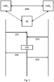
- An exemplary distributed energy conversion system has at least a first energy conversion entity EWE 1 and a second energy conversion entity EWE 2 .
- EWE 1 first energy conversion entity
- EWE 2 second energy conversion entity
- the concept of energy for the modeling in the following includes every carrier, i.e. electrical energy as well as chemically stored energy such as gas or oil, thermal energy, such as geothermal / solar district heating, etc.
- the term energy conversion entity is broadly defined.
- the term includes both energy consumers and energy suppliers.
- Typical energy consumers are “consumption elements" such as engines, while typical energy suppliers are gas generators, electricity generators, and heat generators.
- Storage systems can therefore act both as an energy supplier in the discharge cycle and as an energy consumer in the charge cycle.
- it can be assumed that at a certain point in time when an energy flow occurs, there is at least one consumer and at least one supplier. That is to say, with the invention it is also possible to control different energy sources in a substitute manner for one another. That means, depending on the parameters / data, a certain energy source can make more sense than another at one point in time. The system thus allows unrivaled flexibility.
- the energy can be exchanged between the individual energy conversion entities via one or more energy exchange networks EAN.
- At least one evaluation entity BE is also provided, which can communicate with the energy conversion entities EWE 1 , EWE 2.
- Communication is broadly defined and can include both “internal communication", for example in the case of an integrated structure - more on this later - or more generally also “external communication" with a physically separate unit.
- internal communication for example in the case of an integrated structure - more on this later - or more generally also “external communication” with a physically separate unit.
- the approach described here is due to the underlying logical model. Communication can take place via any suitable medium and is not tied to a specific means of communication. In particular, however, it can be provided that the individual energy conversion entities as well as the evaluation entity BE over the energy exchange network EAN can communicate, for example using technologies such as Powerline.
- first energy conversion entity EWE 1 acts as an energy supply element at a first point in time
- second energy conversion entity EWE 2 acts as an energy consumption element.
- this can be different, as already described, ie the first energy conversion entity EWE 1 act as an energy consumption element at a further point in time and the second energy conversion entity EWE 2 act as an energy supply element .
- the first energy conversion entity EWE 1 provides data relating to the provision of energy to the evaluation entity BE in a step 100, the data comprising one or more of the: availability period, availability amount, costs / energy unit, amount of pollutants / Unit of energy, storage status for one or more future periods.
- the type and selection of the data that can be transmitted is of course dependent on the respective energy conversion entity and / or the carrier used in the energy exchange network.
- the temporal flow rate e.g. m 3 / s
- the flow quantity calorific value / time e.g. kWh / s or kW
- the state number and environmental parameters are known.
- data relating to a period of availability are exchanged, e.g. offer 30 kWh in a period of 1 h with a maximum flow rate of 500 W.
- other data such as measured values on the device, setpoint values of the device, user inputs, etc. can of course also be transferred .
- the second energy conversion entity EWE 2 provides data relating to the purchase and / or use and / or storage of energy to the evaluation entity BE in a step 150, the data having one or more of the following: Acceptance period, acceptance quantity, storage status for one, two or more future periods.
- the type and selection of the data that can be transmitted is of course dependent on the respective energy conversion entity and / or the carrier used in the energy exchange network.
- the temporal flow rate eg m 3 / s
- the flow variable calorific value / time eg kWh / s or kW
- the state number and environmental parameters are known.
- data relating to the acceptance period e.g. required 30 kWh in a period of 1 hour with a maximum flow rate of 500 W, can be exchanged.
- other data such as measured values on the device, user inputs, etc., can of course also be transmitted.
- certain data can of course also be stored in a memory device or database (not shown) and additionally received or queried from the evaluation entity in relation to an energy conversion entity.
- the evaluation entity BE After receiving the data, which of course can arrive at the evaluation entity BE in any order or in parallel, the evaluation entity BE can carry out an evaluation of the data made available in a step 200 in order to create a schedule for the consumption of energy.
- This schedule can then be made available to the participating energy conversion entities EWE 1 , EWE 2 at the same time or one after the other in a step 300 or a step 350.
- the logical functionality of the energy conversion entities EWE 1 , EWE 2 as well as the evaluation entity BE can be implemented, for example, by energy agents that are in the respective "physical" devices, ie the energy conversion entities EWE 1 , EWE 2 is included or is assigned to them. That is to say, to the extent that energy agents are used below, this means an exemplary implementation of the logic concerned.
- the schedule of energy use and provision can now be influenced by influencing the system-inherent parameters of the purchase and / or use and / or storage of energy, for example of the second energy conversion entity EWE 2 , through the schedule will.
- the energy conversion system presented not only allows demand control, but in principle also integrates a generator control.
- the invention thus turns its back on previous systems that have attempted either only by means of demand control or only by means of demand control and allows a far more efficient and complex control not only of one energy source, but also of a large number of energy sources.
- the first energy conversion entity EWE 1 is a power source, for example a wind turbine. This can, for example, provide a certain amount of energy with certain parameters in the time up to sunset, since experience has shown that other energy consumers (e.g. lamps) then take the energy. From midnight, however, the consumption of these consumers decreases, so that the energy is available again for others.
- a power source for example a wind turbine.
- the second energy conversion entity EWE 2 is a washing machine that can spread the individual washing steps over time, for example a first wash cycle at a temperature X corresponding to a first power consumption over a first period of time Z 1 , followed by a spin cycle corresponding to a second power consumption over a second period of time Z 2 , followed by a wash cycle corresponding to a third power consumption over a third period of time Z 3 .
- the evaluation entity BE can now create a schedule with knowledge of this data, for example the period Z 1 should start at the point in time ZP 1 , so that the period Z 1 ends in good time before sunset.
- the spin cycle (second period Z 2 ) can then begin after midnight. This schedule can then be made available to both the EWE 2 washing machine and the EWE 1 wind turbine generator.
- a tumble dryer could be operated with both electricity and waste heat from a solar thermal system.
- the electricity supply as well as the gas supply it can now be decided which energy carrier is used when. For example, at the beginning of a drying process, there can be strong wind, so that there is a high supply of electricity, while a high level of solar irradiation then leads to a corresponding thermal supply.
- the respective energy carrier or the respective usage periods can now be determined depending on the supply and the expected demand.
- the type of energy conversion can be very different.
- the type of energy conversion can be categorized into the following (non-exhaustive) properties: Energy consumption, generation or storage Examples working constantly Light bulbs, devices in standby mode, batteries, special types of (small) power plants tasks dependent White goods (such as washing machines, dishwashers, etc.), Industrial companies (e.g. for start-up and shutdown processes) etc. depending on the environment Wind power and photovoltaic systems repetitive Refrigerators, central heating, ⁇ KWK systems dynamically adjustable Storage power plants, gas power plants, gas turbines, compressors, gas storage, etc.
- Energy flows can depend on external conditions or specific system settings. This applies, for example, to environment-dependent systems such as wind power or photovoltaic systems, which generate energy depending on the current weather conditions and the position of the sun. However, this also applies to dynamically controllable systems that generate or consume energy depending on the corresponding set points.
- Another exemplary task is to transform the individual, system-specific parameters of technical systems into a uniform database in order to be able to determine the resulting energy flows.
- time-dependent energy flows and the resulting amounts of energy form a suitable basis for this, which, however, must be differentiated and evaluated according to the type of energy carrier used, such as electricity or gas. It is crucial that the resulting model is able to map the behavior over time and thus the inherent dynamics of the technical systems.
- This logical model can now also be embodied in that the evaluation entity BE, as in Figure 1 represented logically, also physically separated from the energy conversion entities EWE 1 , EWE 2 .
- the evaluation entity can be in its own control center of a house or machine control or it can also be part of so-called smart devices or facilities such as smart meters.
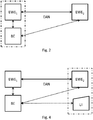
- the evaluation entity BE shown for example, be integrated into the energy conversion entities EWE 1 .
- the data exchange between the logical energy conversion entity EWE 1 ie between the energy agent of the energy conversion entity EWE 1 and the evaluation entity BE can then take place, for example, via an (internal) communication interface.
- the evaluation entity BE is part of the first energy conversion entity EWE 1 and / or part of the second energy conversion entity EWE 2 , because the logical model does not require a clear localization of an evaluation entity.
- an energy conversion entity EWE 1 , EWE 2 can certainly also be connected to several evaluation entities BE and can also exchange data with several evaluation entities BE.
- the evaluation entity can also be made, for example, for the evaluation entity to provide alternatives, ie alternative (execution) timetables. Then it can make sense for the respective energy conversion entity EWE 1 , EWE 2 to decide on the basis of other criteria whether it chooses one or none of the alternatives. This decision can then be communicated to the evaluation entities BE.
- data or information sources for further processing or for controlling a system can be differentiated as follows:
- This type can include the information that can be influenced by an external intervention in the technical system and that thus change the energy flows at the limits of the system.
- these can be the setpoints of the system control, which are generated by an external control unit (such as the energy agent) and can be changed automatically with the aid of appropriate communication protocols.
- an external control unit such as the energy agent
- this type usually cannot allow any changes to be made by an end-user.
- the information that can be changed or specified by an end user can be summarized in this group. This can be, for example, a desired room temperature or a predefined room temperature profile for a day. In contrast to the flexibility information described above, the information in this group cannot initially be changed by automated control processes.
- This group can initially include the system-specific sensor information and thus the measured values that are available on a technical system. This group can also include the current setpoints of the system control and, if there is a related dependency, corresponding information about the surroundings. Typically, read-only access to the information providers and sources is used to record this information.
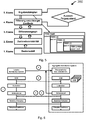
- topology data and / or system states of the energy exchange network EAN are also made available to the evaluation entity BE, the topology data and / or system states also being taken into account in the evaluation.
- This topology data can either be made available externally (push) and / or from a database DB and / or by means of other services such as a web service - as in Figure 3 indicated - be queried (pull).
- a user of an energy conversion entity can enter data relating to this energy conversion entity EWE 1 , EWE 2 .
- input means that the user specifies the data himself, e.g. a desired setpoint temperature, a desired duration, etc.
- Input includes any form of input, e.g. direct input to the relevant or another energy conversion entity EWE 1 , EWE 2 , a direct input to the evaluation entity BE, or an input via a remote application, for example a telephone app or a web service.
- Such an input can, for example, as in Figure 3 indicated by means of a user interface UI in a step 160. This data can then be taken into account in the same way in the assessment.
- the user interface UI can also be used as in Figure 4 shown as part of an energy conversion entity, here energy conversion entity EWE 1 .
- forecast data is made available externally to the evaluation entity BE in a step 170 (push) and / or from one or more databases DB - as in FIG Figure 3 indicated - be queried (pull).
- forecast data represent information from system variables that have already been defined, directed forward in time.
- the invention offers two options, by way of example, for making forecast data available for the evaluation.
- static forecast measurement series can be stored here.
- cost unit must first be defined, with the help of which these costs are to be summarized. Monetary units come into consideration here. In addition, however, other cost units are also conceivable that can describe the operational use of a system in an equivalent manner. For example, the quantities of carbon dioxide (CO 2 ) produced or saved can be used here, which could be used with appropriately formulated cost functions to evaluate the quantities of energy converted by a technical system accordingly. Cost or conversion units can thus be specified, for example, in “euros per kWh” or in "tons of CO 2 per MWh".
- the amounts of energy converted over time by a technical system can form the basis for its operational evaluation.
- different and sometimes time-dependent cost functions can be used depending on the energy source used and the system-related flow direction. Examples include demand response approaches, the differing rates of remuneration for the extraction or supply of electrical energy to a prosumer, or the connection of a technical system to different networks.
- the system for calculating the costs or income for an operating state defined by the model is designed to combine and add up the partial results of various calculation steps and methods.
- the basis for this can be a description of the state of a technical system, which records the energy-carrier-dependent energy flows at the network connections of a technical system for a defined period of time.
- individually defined cost functions can be used to evaluate the price of the energy turnover in an operating state.
- the sum of the expenses or income related to the energy flows can represent the first aspect for the operational evaluation of individual, time-limited operating and system states.
- forecast data relating to at least one of the energy conversion entities EWE 1 , EWE 2 are made available to the evaluation entity BE, the data having one or more of the following: energy generation or use, storage volume and state for one or more future time periods.
- both the time spans to be considered and the evaluation criteria for the amount of energy converted can differ.
- both short-term decisions e.g. for the "fast" stabilization of a local network in the seconds and minutes range
- medium and long-term plans that extend over a period of several hours or days.
- the model can support the pursuit of different objectives.
- certain information that can be used in the context of a state space evaluation can be advantageous. In accordance with the objectives made possible by the invention, this particular information is identified and briefly explained below:
- the invention offers the information required for this about the input and output information, the basic model and the possibility of describing the state of a technical system over time. With the help of the accumulated energy expenditure, the amount of energy transported at an interface and over time can be updated. In addition to this, the energy loss that results from the current efficiency of a system can also be of interest. For this purpose, there is also the option of adding up these values over time in the course of the evaluation process. Analogous to the explanations about the short-term stabilization of system connections, forecasts of measurement and default values can also be advantageous for these optimization goals.
- This optimization goal too, first of all requires a consideration of the current operating status and a determination of the amounts of energy that have accumulated over time.
- an optimization geared towards costs additionally requires the definition of a suitable cost model that summarizes the amounts of energy consumed or generated over time with the aid of suitable cost functions under a common cost unit. Analogous to forecast values, this information can also be available for the optimization period under consideration and can also change over time.
- evaluation unit BE can also pursue more than one goal, it being possible for the goals to be weighted, which in turn can be dependent on user specifications or other parameters.
- step 200 If the evaluation process in step 200 is viewed as a forward-looking, systematic search for an optimized schedule, the most varied of states of a technical system can be determined with the aid of the time steps described by the operating states.
- the first level represents a basic model that can include all parameters describing the system. This can include the internal and external information sources mentioned as well as connection configurations, network connections, energy carriers involved, operating states, operating state transitions and energy-carrier-dependent energy flows, etc. All other levels use the information provided here.
- the second level offers answers regarding the possible flexibility of a technical energy conversion process. Depending on the current state of a system, this can answer the question of which system states could be set as subsequent states by definition.
- the system can provide a search graph that makes it possible to map the state space that has already been determined and to reuse determined energy flows and the corresponding costs.
- the fourth level offers support with regard to time restrictions as well as possible storage states, so that the final, fifth level can represent the completed result schedules. The levels, which are only briefly described here, are explained in more detail below.
- G ZV (V, E) describes a directed graph for the state variability of a technical system, where the node V describes the finite set of all operating state and setpoint-dependent states of a system and E, the edges of the graph, the finite set of all possible Transitions between these states.
- the initial state of the system defined for the evaluation is first used to create the first node of the graph.
- possible subsequent states are then determined. It should be noted that a variation of setpoints can lead to a multiplication of the possible subsequent states.
- the possible subsequent values can easily be determined for individual target values. In the combination of several setpoints, however, the total amount of possible subsequent states results from the cross product of all individual setpoint variations.
- the subsequent states Once the subsequent states have been determined for a state, corresponding nodes are created for this. This procedure can then be applied recursively to one or more subsequent states until the associated operating state and setpoint variations of the technical system have been determined and mapped.
- a simple hash process can be used, which uses the current operating status and the current setpoint values as a basis. The resulting number of nodes is highly dependent on the system under consideration, but does not pose any major challenges in terms of memory load or performance. In the next level of the basic system, however, it can save the need to re-instantiate and carry out the procedure described here for determining subsequent states.
- the solution approach designed for this problem is addressed by the third level of the basic system described here.
- the basis for this is the already described clear identification of the state of a technical system.
- This can be used at this level to build a difference graph that describes the possible states of a technical system over time.
- the nodes of this graph can contain the temporal system states with all input and output values as well as the energy flows present at the network connections of the technical system at this point in time.
- the initial or initial state can first be identified. In a real system, this can be done, for example, by recording current measured values and energy flows. In the context, this is generally specified by the settings in preparation for the evaluation. With the defined initial status, a complete and precise description of all status values is available. This can include (all) input and output information (including updated forecast values), all energy flows present at the specific point in time at the connection points and, if available, the storage states of the energy storage devices in the system. Cumulative amounts of energy, resulting costs and energy flows are 0 at this point in time.
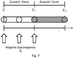
- the model can, for example, at the same time also describe the time period for an operating state for which it is defined.
- the specific starting time for an initial state Z S can be, for example, directly at the beginning, in the middle or at the end of a defined operating state, see in this regard Figure 7 .
- the resulting state Z i + 1 thus represents the first state in which a decision regarding the flexibility of a system can be made.
- the task of the edges of the graph is to describe the changes that are produced by a selected subsequent state. Based on the duration and the energy flows of an operating state (including losses), these changes can initially include the amounts of energy that are transferred via the individual network connections of the technical system. This can also include the energy carrier-dependent costs or income generated. Based on this, the determine the further course of the balanced resulting energy turnover and the corresponding change in relation to the total costs.
- the calculation steps used here essentially correspond to the method presented in the context of the cost model for determining the total costs, but according to the model assumptions can only apply to a selected operating state and a variant of the possible target value combinations. In addition, the information about the converted energy flows and quantities can be retained for reuse.
- the difference graph does not generally have to be created. Rather, it can be used, for example, if the basic system of the energy option model described here is applied. However, the graph is not created directly and in full over the entire evaluation period, but can only be created at the points where a search process is currently located. Starting from a previous state, the graph of the state variability can initially be used to determine all possible changes for the operating state and setpoint values. Based on this, all of the changes that correspond to this, as well as the resulting subsequent states, can then be determined. There is no need to expand the graph behind unvisited nodes or system states.
- the difference graph can already take concrete system states into account, but it only focuses on the energy flows at the limits of a technical system. This results from the approach to the unambiguous identification of a system state, which also makes the nodes identifiable in the difference graph.
- the system parameters can be specified that have a direct or indirect influence on the energy flows at the limits of the technical system.
- the specific memory states of a technical system have not yet been taken into account. Furthermore, the time restrictions that can be defined with minimum and maximum dwell times for individual operating states have not yet been taken into account. In addition, the control values controlled by the controller of a system should also be kept within the specified limits.
- the outgoing edges of the difference graph can be used to check how large possible changes can be in relation to the fill levels of a memory. If the status resulting from a change is less than 0 or greater than the specified storage capacity, this subsequent status is excluded from further considerations.
- the monitoring and filtering to comply with the minimum and maximum time restrictions for an operating state may require the prior operating states to be taken into account.
- For the minimum duration an operating state may only be exited if the defined minimum dwell time has been exceeded. Accordingly, the decision as to which subsequent state may be adopted at a specific point in time can depend on this. If the defined minimum time in the series of previous states has not yet been reached, this reduces the list of possible next operating states accordingly.
- For the maximum duration an operating state should be exited when the maximum period of time for an operating state is exceeded.
- a backward-looking search process can be used to check this restriction and to reduce the list of possible subsequent states if necessary.
- the last aspect, which can be checked in the 4th level, is the regulation of the technical system, given limit values of specific measured values. If a calculated new measured value exceeds or falls below the specified control range, the new system status resulting from the changes can be filtered out.
- the result of an evaluation and thus the schedule for a technical system is represented in the model by the state that was determined for the end of the evaluation period.
- the system states upstream in time can be stored recursively.
- a subsequent state can thus be determined or selected step by step.
- the reference to the current status can then be saved in the storage of the subsequent status.
- the evaluation run can be continued in this way.
- the search for creating an individual schedule in step 200 can proceed in such a way that, based on the initially defined system state, which can be within the period of an operating state, it can first be ensured that this is calculated until the end of the operating state will. This means that the converted energy quantities and costs are determined up to the end of the current operating state and thus the first edge in the difference graph is also generated.
- the subsequent node and the state of the technical system that corresponds to it represent the starting point for the cyclical search process that uses the described auxiliary levels 2 to 4 for this purpose.
- the difference graph can be used to query which variation of subsequent statuses exist for the current system status. If these have not yet been determined for the requested time and the associated system status, they can be generated on request.
- the graph of the state variability can first be used to determine which changes are possible in relation to operating states and setpoints by definition in the basic model. From this, the possible changes in relation to energy flows and quantities, the corresponding costs and the subsequent states can be determined - the latter can be mapped at the same time by new nodes in the difference graph.
- the 4th level of the basic system can check and filter the admissibility of the possible changes.
- the subsequent states identified by the difference graph can be checked with regard to memory states and time restrictions to be observed, so that only validated and applicable subsequent states are returned to the result level. After that it can be the job of one Decision-making process to determine the next system state.
- the Figure 5 graphically depicts the context of the assessment in step 200 as well as a structural structure of a result timetable, whereby the result timetable is then in the context of the assessment as TSSE (final) from the intermediate timetables TSSE (initial), TSSE (2nd level) determined in each case ) ... TSSE (4) results.
- step 200 it is also possible to parallelize the partial steps within step 200.
- the sub-steps and levels presented are only examples of a model.
- the parallelization of evaluation strategies which is basically possible by executing several evaluation threads, can also be implemented for the step-by-step basic system presented here.
- the simultaneous creation of nodes for a system state is the main problem, as it can lead to inconsistent or even overwritten node instances within the graph.
- a locking procedure was developed that prevents the simultaneous creation of nodes for one and the same system state.
- the simultaneous creation of state nodes can be prevented.
- the created node can be assigned a lock that can only be released again by the thread creating the node.
- the model enables several systems to be viewed at the same time.
- the system concept and thus the encapsulation of individual systems is used as the basis for describing a system of systems.
- the aggregation itself can represent its own system, while all subsystems to be taken into account can still be handled in the manner described above. Any complex combinations of systems can thus be configured, for example as a tree-like structure, in which individual systems are used in the form described above or can be represented by alternative or individual timetables.
- the concept of the step-by-step approach to evaluating individual systems can be expanded and adapted will.
- network status calculations can be carried out within the framework of the application of an individual evaluation strategy. Analogous to individual systems, individual strategies can also be developed and implemented here.
- the model is also suitable for add-hoc decision-making processes that can be used, for example, in the area of technical control.
- the continuously updated system states of the systems involved can be used to determine current options for action for each energy conversion process.
- An evaluation process based on the current time could run ahead of the current time and pre-evaluate the possible subsequent states. Since these evaluation results are stored in the difference graph of the relevant system, this also leads to an accelerated response time behavior, which is of enormous importance for time-critical applications.
- One aim of the invention is to first describe the flexibility of a technical one and to make it usable or controllable in the sense of a higher-level objective.
- the structure of the model enables the description of any energy conversion processes as well as the consideration of different energy sources, such as electricity and natural gas.
- This hybrid approach is not limited to the mapping of the existing flexibility in terms of operating states, setpoint variations and the resulting energy flows, but rather supports the development of new, as yet non-existent operating and system states.
- the point of contact for the control of individual technical systems is thus initially the information technology interface that is offered by the control of a system.
- One aim of the invention is to be able to functionally map the relationship between this information and the corresponding energy flows in order to be able to serve as a basis for realistic and thus reliable forecasting, monitoring and optimization processes.
- So-called system variables are defined in the model as a description of the measured values, control setpoints and user specifications available on the system.
- the model also allows the definition of static data models and the definition of system variables that cannot be determined directly on the technical system, but only via external information services. In this way, for example, static maps of systems on the one hand or external weather information on the other hand can be defined and used in the energy option model. All system variables together serve the purpose of describing the basic, input and output information that influences the energy flows occurring in an energy conversion process.
- the basic model of the model of the invention includes first of all the definition of the system boundaries that connect a single system with one or more energy networks and the corresponding energy sources, as well as the possible connection variations.
- the different connection options of an electric car can be described (see e.g. IEC 62196 ) or the different ways of using a system (e.g. for different programs for white goods devices).
- the modeling of the operating states of a system can be made possible by a directed graph.
- the nodes of the graph represent the individual, time-limited operating states, while the directed edges describe the possible sequence of these states.
- the length of stay in an operating state can also be limited, for example to protect a system or to take into account the memory status of a system.
- corresponding energy flows can be defined for each operating state.
- functions for the minimum and maximum dwell time in an operating state possible energy flow gradients or calculation methods that can be used to determine loss energies can be defined.
- temporal system states are first defined, which at the same time define the evaluation period to be considered.
- forecast functions for the period under consideration can be defined in different ways. In this way, for example, weather information can be made available for the period under consideration, which can be used in the context of corresponding calculations to determine the amount of electricity produced by a photovoltaic system.
- the model also offers an open approach for evaluating the operational use of energy conversion processes.
- individual cost functions can be defined, which on the one hand can evaluate the energy flows occurring in the system, but on the other hand also the specific operating states of a system. This can be used, for example, to define evaluation parameters in € / kWh or kg - CO 2 / MWh , which can be applied to the specific conditions, performance parameters and time periods as part of the system evaluation.
- the model In addition to using the open interface to create a system timetable, the model also offers a special, step-by-step procedure for generating timetables, which can also be used as part of individual evaluation strategies.
- mapping the system states in a difference graph system states and possible subsequent states can be mapped.
- control decisions can be qualified by quantifying parameters such as performance and storage sizes, which makes making control decisions well-founded and thus considerably simpler.
- a detailed result schedule can be made available, which can represent a detailed description of the temporal system states. This can contain both the basic, input and output information of the system, as well as the resulting energy flows, which can depend on these parameters.
- the result schedule can also represent a serializable element so that it can be communicated via an exchange of messages if necessary.
- the model of the invention enables the simultaneous consideration of several technical systems that represent a grid-connected energy conversion process.
- the system concept and thus the encapsulation individual systems are used as the basis to describe a system of systems.
- the aggregation itself can represent its own system, while all subsystems to be taken into account can still be handled in the manner described above. Any complex combinations of systems can thus be configured as a tree-like structure in which individual systems are used in the form described above or can be represented by alternative or individual timetables.
- the concept of the step-by-step approach to evaluating individual systems can be expanded and adapted.
- network status calculations can be carried out within the framework of the application of an individual evaluation strategy. Analogous to individual systems, however, individual strategies can also be developed and implemented here. The flexibility resulting from the approach with regard to the location of decision-making processes was made possible by Figure 6 . presented.
- the data in a certain structure, for example an XML format.
- techniques such as SOAP or REST can also be used to query data.
Landscapes
- Engineering & Computer Science (AREA)
- Power Engineering (AREA)
- Management, Administration, Business Operations System, And Electronic Commerce (AREA)
Claims (9)
- Système distribué de conversion d'énergie, dans lequel le système distribué de conversion d'énergie présente :• au moins une première entité de conversion d'énergie (EWE1), une deuxième entité de conversion d'énergie (EWE2), et une troisième entité de conversion d'énergie (EWE3),• dans lequel les entités de conversion d'énergie (EWE1, EWE2, EWE3) sont reliées entre elles via un réseau d'échange d'énergie (EAN),• dans lequel le système distribué de conversion d'énergie est étudié pour intégrer au moins l'une des entités de conversion d'énergie (EWE1, EWE2, EWE3) du groupe présentant la première entité de conversion d'énergie (EWE1), la deuxième entité de conversion d'énergie (EWE2), et la troisième entité de conversion d'énergie (EWE3), de manière dynamique dans une agrégation, ou pour la retirer de manière dynamique de celle-ci, du système distribué de conversion d'énergie,• présentant en outre une entité d'évaluation (BE),• dans lequel les entités de conversion d'énergie (EWE1, EWE2, EWE3) et l'entité d'évaluation (BE) disposent respectivement d'une unité de communication,• dans lequel l'unité de communication de l'entité d'évaluation (BE) est étudiée pour communiquer avec les entités de conversion d'énergie (EWE1, EWE2, EWE3),• dans lequel la première entité de conversion d'énergie (EWE1) présente, à un premier moment, la propriété d'un élément d'alimentation en énergie et la deuxième entité de conversion d'énergie (EWE2) présente la propriété d'un élément de consommation d'énergie,
caractérisé en ce que• la première entité de conversion d'énergie (EWE1) est étudiée pour fournir des données concernant la fourniture d'énergie à l'entité d'évaluation (BE), dans lequel les données présentent l'un(e) ou plusieurs parmi ce qui suit : période de disponibilité, quantité disponible, coûts/unité d'énergie, quantité de polluants/unité d'énergie, état d'accumulation pour une ou plusieurs périodes futures,• la deuxième entité de conversion d'énergie (EWE2) est étudiée pour fournir des données concernant la consommation et/ou l'emploi et/ou l'accumulation d'énergie à l'entité d'évaluation (BE), dans lequel les données présentent l'un(e) ou plusieurs parmi ce qui suit : période de consommation, quantité consommée, quantité accumulée pour deux ou plusieurs périodes futures,• l'entité d'évaluation (BE) est étudiée pour ensuite procéder à une évaluation des données fournies pour établir une feuille de route pour la consommation d'énergie, dans lequel l'entité d'évaluation (BE) est un élément constitutif de la première entité de conversion d'énergie (EWE1) et/ou un élément constitutif de la deuxième entité de conversion d'énergie (EWE2). - Système distribué de conversion d'énergie selon la revendication 1, caractérisé en ce que, grâce à la feuille de route, une influence s'exerce sur les paramètres inhérents au système de la consommation et/ou l'emploi et/ou l'accumulation d'énergie de la deuxième entité de conversion d'énergie (EWE2).
- Système distribué de conversion d'énergie selon l'une des revendications précédentes, caractérisé en ce que l'entité d'évaluation est étudiée pour obtenir des données de topologie et/ou des états de système du réseau d'échange d'énergie (EAN), dans lequel les données de topologie et/ou états du système sont pris en compte lors de l'évaluation.
- Système distribué de conversion d'énergie selon l'une des revendications précédentes, caractérisé en ce que l'entité d'évaluation est en outre étudiée pour obtenir des données concernant l'une des entités de conversion d'énergie (EWE1, EWE2) d'un utilisateur de l'unité de conversion d'énergie (EWE1, EWE2), dans lequel les données manuelles sont prises en compte lors de l'évaluation.
- Système distribué de conversion d'énergie selon l'une des revendications précédentes, caractérisé en ce que l'entité d'évaluation (BE) est étudiée pour obtenir des données sur l'environnement.
- Système distribué de conversion d'énergie selon l'une des revendications précédentes, caractérisé en ce que la deuxième entité de conversion d'énergie (EWE2) est étudiée pour fournir des données d'utilisateur par rapport à la deuxième entité de conversion d'énergie (EWE2) à l'entité d'évaluation (BE), dans lequel les données présentent des préférences utilisateur, pour une ou plusieurs périodes futures.
- Système distribué de conversion d'énergie selon l'une des revendications précédentes, caractérisé en ce que la première entité de conversion d'énergie (EWE1) est étudiée pour fournir des données d'utilisateur par rapport à la première entité de conversion d'énergie (EWE1) à l'entité d'évaluation (BE), dans lequel les données présentent des préférences utilisateur pour une ou plusieurs périodes futures.
- Système distribué de conversion d'énergie selon l'une des revendications précédentes, caractérisé en ce que l'entité d'évaluation (BE) est étudiée pour obtenir des données de prévision par rapport à au moins l'une des entités de conversion d'énergie (EWE1, EWE2), dans lequel les données présentent l'un(e) ou plusieurs parmi ce qui suit : production d'énergie, volume d'accumulation pour une ou plusieurs périodes futures.
- Système distribué de conversion d'énergie selon l'une des revendications précédentes, caractérisé en ce que l'entité d'évaluation (BE) est étudiée pour traiter des données concernant une pluralité de sources d'énergie, dans lequel les sources d'énergie sont sélectionnées dans un groupe présentant de l'énergie électrique, de l'énergie stockée sous forme chimique, de l'énergie thermique.
Applications Claiming Priority (2)
| Application Number | Priority Date | Filing Date | Title |
|---|---|---|---|
| LU92742A LU92742B1 (de) | 2015-06-16 | 2015-06-16 | Verteiltes energie-wandlungs-system |
| PCT/EP2016/063834 WO2016202903A1 (fr) | 2015-06-16 | 2016-06-16 | Système distribué de conversion d'énergie |
Publications (2)
| Publication Number | Publication Date |
|---|---|
| EP3311460A1 EP3311460A1 (fr) | 2018-04-25 |
| EP3311460B1 true EP3311460B1 (fr) | 2022-01-05 |
Family
ID=53724420
Family Applications (1)
| Application Number | Title | Priority Date | Filing Date |
|---|---|---|---|
| EP16731092.9A Active EP3311460B1 (fr) | 2015-06-16 | 2016-06-16 | Système distribué de conversion d'énergie |
Country Status (4)
| Country | Link |
|---|---|
| US (1) | US11056887B2 (fr) |
| EP (1) | EP3311460B1 (fr) |
| LU (1) | LU92742B1 (fr) |
| WO (1) | WO2016202903A1 (fr) |
Families Citing this family (1)
| Publication number | Priority date | Publication date | Assignee | Title |
|---|---|---|---|---|
| US11244410B2 (en) * | 2020-02-24 | 2022-02-08 | Leading Edge Power Solutions, Llc | Technologies for dynamically dispatching generator power |
Family Cites Families (7)
| Publication number | Priority date | Publication date | Assignee | Title |
|---|---|---|---|---|
| US9494993B2 (en) * | 2010-06-26 | 2016-11-15 | Lg Electronics Inc. | Washing machine capable of communicating with a network system |
| WO2012129675A1 (fr) * | 2011-03-31 | 2012-10-04 | Energent Incorporated | Système et procédé de gestion d'un concentrateur d'énergie électrique assisté par ordinateur |
| EP2695270B1 (fr) * | 2011-04-08 | 2014-12-31 | SMA Solar Technology AG | Gestion de puissance de charge |
| JP6178045B2 (ja) * | 2012-04-16 | 2017-08-09 | 株式会社東芝 | エネルギー管理システム、エネルギー管理方法、プログラムおよびサーバ装置 |
| JP6192907B2 (ja) * | 2012-08-06 | 2017-09-06 | 京セラ株式会社 | エネルギー管理装置、エネルギー管理システムおよびエネルギー管理方法 |
| DE102013222277A1 (de) * | 2013-03-15 | 2014-09-18 | Cbb Software Gmbh | Steuerung von dezentralen Energieerzeugern und/oder Verbrauchern in einem elektrischen Verbundnetz |
| US20150112500A1 (en) * | 2013-10-17 | 2015-04-23 | Honeywell International Inc. | Demand response system having a renewable energy source |
-
2015
- 2015-06-16 LU LU92742A patent/LU92742B1/de active
-
2016
- 2016-06-16 EP EP16731092.9A patent/EP3311460B1/fr active Active
- 2016-06-16 US US15/737,029 patent/US11056887B2/en active Active
- 2016-06-16 WO PCT/EP2016/063834 patent/WO2016202903A1/fr active Application Filing
Non-Patent Citations (1)
| Title |
|---|
| REDDY S. YOGENDRA ET AL: "A modular power electronic transformer for medium voltage application", ELECTRICAL ENGINEERING. PNC & VIET, 30 September 2012 (2012-09-30), XP055296199, Retrieved from the Internet <URL:https://www.researchgate.net/profile/Yogendra_Reddy/publication/230918050_A_modular_power_electronic_transformer_for_medium_voltage_application/links/0fcfd506069047985c000000.pdf?origin=publication_detail> [retrieved on 20160818] * |
Also Published As
| Publication number | Publication date |
|---|---|
| US11056887B2 (en) | 2021-07-06 |
| US20180159332A1 (en) | 2018-06-07 |
| WO2016202903A1 (fr) | 2016-12-22 |
| LU92742B1 (de) | 2016-12-19 |
| EP3311460A1 (fr) | 2018-04-25 |
Similar Documents
| Publication | Publication Date | Title |
|---|---|---|
| DE102016214332B4 (de) | Aggregierte und optimierte virtuelles-kraftwerk-steuerung | |
| DE102011051673A1 (de) | Energieverwaltungssystem | |
| DE102011051671A1 (de) | Optimierungssystem unter Verwendung einer iterativen Experten-Engine | |
| EP3469680B1 (fr) | Procédé, produit programme informatique, dispositif et système de 'service de cluster énergétique' pour gérer des objectifs de régulation, notamment de compensation de charge, lors de la commande de l'approvisionnement, de la conversion, du stockage, de l'alimentation, de la distribution et/ou de la consommation d'énergie dans un réseau d'énergie | |
| EP2633600B1 (fr) | Procédé de détection de données à cycle court, pour la surveillance de l'énergie et pour la commande de réseau dans le système de compteur intelligent/réseau électrique intelligent à l'aide d'un logiciel médiateur intelligent distribué | |
| EP3251076A1 (fr) | Procédé d'amélioration de la charge d'un réseau à basse tension | |
| CH713282A1 (de) | Verfahren zur Strukturierung eines vorhandenen Netzes zur Verteilung von elektrischer Energie. | |
| WO2008125171A1 (fr) | Procédé pour l'optimisation, la planification et/ou le contrôle de développement systématiques d'un système | |
| Capitanescu | AC OPF-based methodology for exploiting flexibility provision at TSO/DSO interface via OLTC-controlled demand reduction | |
| DE102014217929A1 (de) | Energiemanagementsystem zur Steuerung einer Einrichtung, Computersoftwareprodukt und Verfahren zur Steuerung einer Einrichtung | |
| WO2020043522A1 (fr) | Procédé de commande d'un échange d'énergie entre des sous-systèmes énergétiques dans des conditions harmonisées ; centrale de commande ; système énergétique ; programme informatique et support d'enregistrement | |
| EP3311460B1 (fr) | Système distribué de conversion d'énergie | |
| WO2016120248A1 (fr) | Procédé d'amélioration de la répartition des charges d'un réseau basse tension | |
| EP1072081A1 (fr) | Procede de reglage de la puissance totale d'installations techniques de production d'energie | |
| EP3664243A1 (fr) | Planification de fonctionnement prédictive dans un micro-réseau en fonction des fenêtres temporelles de charge élevé d'un réseau électrique principal | |
| EP3871178B1 (fr) | Procédé mis en oeuvre par ordinateur pour la gestion décentralisée d'un réseau énergétique | |
| DE102009008033B3 (de) | Versorgung von energietechnischen Objekten mit Energie verschiedener Energiearten | |
| DE10244469B4 (de) | Verfahren zur Bildung physikalischer und struktureller Modelle verteilter Kraft-Wärmekopplungsanlagen | |
| EP4014295A1 (fr) | Procédé pour modéliser une ou plusieurs installations de conversion d'énergie dans un système de gestion d'énergie | |
| EP4012514A1 (fr) | Procédé de génération d'un plan opérationnel de commande des composants énergétiques d'une infrastructure de bâtiment | |
| DE102023109749A1 (de) | Vorhersage der verbrauchernachfrage nach einem angebot in einergeografischen zone auf der grundlage unzuverlässiger undnichtstationärer daten | |
| EP4176504A1 (fr) | Réseau de distribution d'énergie électrique | |
| WO2021219265A1 (fr) | Procédé de commande d'échanges thermiques et dispositif de commande associé | |
| EP4222567A1 (fr) | Procédé d'intégration d'un composant d'installation industrielle dans un système d'installation industrielle | |
| EP3961980A1 (fr) | Système et procédé de commande d'une pompe à chaleur |
Legal Events
| Date | Code | Title | Description |
|---|---|---|---|
| STAA | Information on the status of an ep patent application or granted ep patent |
Free format text: STATUS: THE INTERNATIONAL PUBLICATION HAS BEEN MADE |
|
| PUAI | Public reference made under article 153(3) epc to a published international application that has entered the european phase |
Free format text: ORIGINAL CODE: 0009012 |
|
| STAA | Information on the status of an ep patent application or granted ep patent |
Free format text: STATUS: REQUEST FOR EXAMINATION WAS MADE |
|
| 17P | Request for examination filed |
Effective date: 20180111 |
|
| AK | Designated contracting states |
Kind code of ref document: A1 Designated state(s): AL AT BE BG CH CY CZ DE DK EE ES FI FR GB GR HR HU IE IS IT LI LT LU LV MC MK MT NL NO PL PT RO RS SE SI SK SM TR |
|
| AX | Request for extension of the european patent |
Extension state: BA ME |
|
| DAV | Request for validation of the european patent (deleted) | ||
| DAX | Request for extension of the european patent (deleted) | ||
| STAA | Information on the status of an ep patent application or granted ep patent |
Free format text: STATUS: EXAMINATION IS IN PROGRESS |
|
| 17Q | First examination report despatched |
Effective date: 20190812 |
|
| STAA | Information on the status of an ep patent application or granted ep patent |
Free format text: STATUS: EXAMINATION IS IN PROGRESS |
|
| GRAP | Despatch of communication of intention to grant a patent |
Free format text: ORIGINAL CODE: EPIDOSNIGR1 |
|
| STAA | Information on the status of an ep patent application or granted ep patent |
Free format text: STATUS: GRANT OF PATENT IS INTENDED |
|
| INTG | Intention to grant announced |
Effective date: 20210817 |
|
| GRAS | Grant fee paid |
Free format text: ORIGINAL CODE: EPIDOSNIGR3 |
|
| GRAA | (expected) grant |
Free format text: ORIGINAL CODE: 0009210 |
|
| STAA | Information on the status of an ep patent application or granted ep patent |
Free format text: STATUS: THE PATENT HAS BEEN GRANTED |
|
| AK | Designated contracting states |
Kind code of ref document: B1 Designated state(s): AL AT BE BG CH CY CZ DE DK EE ES FI FR GB GR HR HU IE IS IT LI LT LU LV MC MK MT NL NO PL PT RO RS SE SI SK SM TR |
|
| REG | Reference to a national code |
Ref country code: GB Ref legal event code: FG4D Free format text: NOT ENGLISH |
|
| REG | Reference to a national code |
Ref country code: CH Ref legal event code: EP |
|
| REG | Reference to a national code |
Ref country code: AT Ref legal event code: REF Ref document number: 1461439 Country of ref document: AT Kind code of ref document: T Effective date: 20220115 |
|
| REG | Reference to a national code |
Ref country code: DE Ref legal event code: R096 Ref document number: 502016014355 Country of ref document: DE |
|
| REG | Reference to a national code |
Ref country code: IE Ref legal event code: FG4D Free format text: LANGUAGE OF EP DOCUMENT: GERMAN |
|
| REG | Reference to a national code |
Ref country code: LT Ref legal event code: MG9D |
|
| REG | Reference to a national code |
Ref country code: NL Ref legal event code: MP Effective date: 20220105 |
|
| PG25 | Lapsed in a contracting state [announced via postgrant information from national office to epo] |
Ref country code: NL Free format text: LAPSE BECAUSE OF FAILURE TO SUBMIT A TRANSLATION OF THE DESCRIPTION OR TO PAY THE FEE WITHIN THE PRESCRIBED TIME-LIMIT Effective date: 20220105 |
|
| PG25 | Lapsed in a contracting state [announced via postgrant information from national office to epo] |
Ref country code: SE Free format text: LAPSE BECAUSE OF FAILURE TO SUBMIT A TRANSLATION OF THE DESCRIPTION OR TO PAY THE FEE WITHIN THE PRESCRIBED TIME-LIMIT Effective date: 20220105 Ref country code: RS Free format text: LAPSE BECAUSE OF FAILURE TO SUBMIT A TRANSLATION OF THE DESCRIPTION OR TO PAY THE FEE WITHIN THE PRESCRIBED TIME-LIMIT Effective date: 20220105 Ref country code: PT Free format text: LAPSE BECAUSE OF FAILURE TO SUBMIT A TRANSLATION OF THE DESCRIPTION OR TO PAY THE FEE WITHIN THE PRESCRIBED TIME-LIMIT Effective date: 20220505 Ref country code: NO Free format text: LAPSE BECAUSE OF FAILURE TO SUBMIT A TRANSLATION OF THE DESCRIPTION OR TO PAY THE FEE WITHIN THE PRESCRIBED TIME-LIMIT Effective date: 20220405 Ref country code: LT Free format text: LAPSE BECAUSE OF FAILURE TO SUBMIT A TRANSLATION OF THE DESCRIPTION OR TO PAY THE FEE WITHIN THE PRESCRIBED TIME-LIMIT Effective date: 20220105 Ref country code: HR Free format text: LAPSE BECAUSE OF FAILURE TO SUBMIT A TRANSLATION OF THE DESCRIPTION OR TO PAY THE FEE WITHIN THE PRESCRIBED TIME-LIMIT Effective date: 20220105 Ref country code: ES Free format text: LAPSE BECAUSE OF FAILURE TO SUBMIT A TRANSLATION OF THE DESCRIPTION OR TO PAY THE FEE WITHIN THE PRESCRIBED TIME-LIMIT Effective date: 20220105 Ref country code: BG Free format text: LAPSE BECAUSE OF FAILURE TO SUBMIT A TRANSLATION OF THE DESCRIPTION OR TO PAY THE FEE WITHIN THE PRESCRIBED TIME-LIMIT Effective date: 20220405 |
|
| PG25 | Lapsed in a contracting state [announced via postgrant information from national office to epo] |
Ref country code: PL Free format text: LAPSE BECAUSE OF FAILURE TO SUBMIT A TRANSLATION OF THE DESCRIPTION OR TO PAY THE FEE WITHIN THE PRESCRIBED TIME-LIMIT Effective date: 20220105 Ref country code: LV Free format text: LAPSE BECAUSE OF FAILURE TO SUBMIT A TRANSLATION OF THE DESCRIPTION OR TO PAY THE FEE WITHIN THE PRESCRIBED TIME-LIMIT Effective date: 20220105 Ref country code: GR Free format text: LAPSE BECAUSE OF FAILURE TO SUBMIT A TRANSLATION OF THE DESCRIPTION OR TO PAY THE FEE WITHIN THE PRESCRIBED TIME-LIMIT Effective date: 20220406 Ref country code: FI Free format text: LAPSE BECAUSE OF FAILURE TO SUBMIT A TRANSLATION OF THE DESCRIPTION OR TO PAY THE FEE WITHIN THE PRESCRIBED TIME-LIMIT Effective date: 20220105 |
|
| PG25 | Lapsed in a contracting state [announced via postgrant information from national office to epo] |
Ref country code: IS Free format text: LAPSE BECAUSE OF FAILURE TO SUBMIT A TRANSLATION OF THE DESCRIPTION OR TO PAY THE FEE WITHIN THE PRESCRIBED TIME-LIMIT Effective date: 20220505 |
|
| REG | Reference to a national code |
Ref country code: DE Ref legal event code: R097 Ref document number: 502016014355 Country of ref document: DE |
|
| PG25 | Lapsed in a contracting state [announced via postgrant information from national office to epo] |
Ref country code: SM Free format text: LAPSE BECAUSE OF FAILURE TO SUBMIT A TRANSLATION OF THE DESCRIPTION OR TO PAY THE FEE WITHIN THE PRESCRIBED TIME-LIMIT Effective date: 20220105 Ref country code: SK Free format text: LAPSE BECAUSE OF FAILURE TO SUBMIT A TRANSLATION OF THE DESCRIPTION OR TO PAY THE FEE WITHIN THE PRESCRIBED TIME-LIMIT Effective date: 20220105 Ref country code: RO Free format text: LAPSE BECAUSE OF FAILURE TO SUBMIT A TRANSLATION OF THE DESCRIPTION OR TO PAY THE FEE WITHIN THE PRESCRIBED TIME-LIMIT Effective date: 20220105 Ref country code: EE Free format text: LAPSE BECAUSE OF FAILURE TO SUBMIT A TRANSLATION OF THE DESCRIPTION OR TO PAY THE FEE WITHIN THE PRESCRIBED TIME-LIMIT Effective date: 20220105 Ref country code: DK Free format text: LAPSE BECAUSE OF FAILURE TO SUBMIT A TRANSLATION OF THE DESCRIPTION OR TO PAY THE FEE WITHIN THE PRESCRIBED TIME-LIMIT Effective date: 20220105 Ref country code: CZ Free format text: LAPSE BECAUSE OF FAILURE TO SUBMIT A TRANSLATION OF THE DESCRIPTION OR TO PAY THE FEE WITHIN THE PRESCRIBED TIME-LIMIT Effective date: 20220105 |
|
| PLBE | No opposition filed within time limit |
Free format text: ORIGINAL CODE: 0009261 |
|
| STAA | Information on the status of an ep patent application or granted ep patent |
Free format text: STATUS: NO OPPOSITION FILED WITHIN TIME LIMIT |
|
| PG25 | Lapsed in a contracting state [announced via postgrant information from national office to epo] |
Ref country code: AL Free format text: LAPSE BECAUSE OF FAILURE TO SUBMIT A TRANSLATION OF THE DESCRIPTION OR TO PAY THE FEE WITHIN THE PRESCRIBED TIME-LIMIT Effective date: 20220105 |
|
| 26N | No opposition filed |
Effective date: 20221006 |
|
| PG25 | Lapsed in a contracting state [announced via postgrant information from national office to epo] |
Ref country code: MC Free format text: LAPSE BECAUSE OF FAILURE TO SUBMIT A TRANSLATION OF THE DESCRIPTION OR TO PAY THE FEE WITHIN THE PRESCRIBED TIME-LIMIT Effective date: 20220105 |
|
| REG | Reference to a national code |
Ref country code: CH Ref legal event code: PL |
|
| REG | Reference to a national code |
Ref country code: BE Ref legal event code: MM Effective date: 20220630 |
|
| PG25 | Lapsed in a contracting state [announced via postgrant information from national office to epo] |
Ref country code: SI Free format text: LAPSE BECAUSE OF FAILURE TO SUBMIT A TRANSLATION OF THE DESCRIPTION OR TO PAY THE FEE WITHIN THE PRESCRIBED TIME-LIMIT Effective date: 20220105 |
|
| PG25 | Lapsed in a contracting state [announced via postgrant information from national office to epo] |
Ref country code: LU Free format text: LAPSE BECAUSE OF NON-PAYMENT OF DUE FEES Effective date: 20220616 Ref country code: LI Free format text: LAPSE BECAUSE OF NON-PAYMENT OF DUE FEES Effective date: 20220630 Ref country code: IE Free format text: LAPSE BECAUSE OF NON-PAYMENT OF DUE FEES Effective date: 20220616 Ref country code: CH Free format text: LAPSE BECAUSE OF NON-PAYMENT OF DUE FEES Effective date: 20220630 |
|
| PG25 | Lapsed in a contracting state [announced via postgrant information from national office to epo] |
Ref country code: BE Free format text: LAPSE BECAUSE OF NON-PAYMENT OF DUE FEES Effective date: 20220630 |
|
| PG25 | Lapsed in a contracting state [announced via postgrant information from national office to epo] |
Ref country code: IT Free format text: LAPSE BECAUSE OF FAILURE TO SUBMIT A TRANSLATION OF THE DESCRIPTION OR TO PAY THE FEE WITHIN THE PRESCRIBED TIME-LIMIT Effective date: 20220105 |
|
| PGFP | Annual fee paid to national office [announced via postgrant information from national office to epo] |
Ref country code: FR Payment date: 20230405 Year of fee payment: 8 Ref country code: DE Payment date: 20230630 Year of fee payment: 8 |
|
| REG | Reference to a national code |
Ref country code: AT Ref legal event code: MM01 Ref document number: 1461439 Country of ref document: AT Kind code of ref document: T Effective date: 20220616 |
|
| PG25 | Lapsed in a contracting state [announced via postgrant information from national office to epo] |
Ref country code: AT Free format text: LAPSE BECAUSE OF NON-PAYMENT OF DUE FEES Effective date: 20220616 |
|
| PGFP | Annual fee paid to national office [announced via postgrant information from national office to epo] |
Ref country code: GB Payment date: 20230405 Year of fee payment: 8 |
|
| PG25 | Lapsed in a contracting state [announced via postgrant information from national office to epo] |
Ref country code: HU Free format text: LAPSE BECAUSE OF FAILURE TO SUBMIT A TRANSLATION OF THE DESCRIPTION OR TO PAY THE FEE WITHIN THE PRESCRIBED TIME-LIMIT; INVALID AB INITIO Effective date: 20160616 |