EP3311460B1 - Distributed energy conversion system - Google Patents
Distributed energy conversion system Download PDFInfo
- Publication number
- EP3311460B1 EP3311460B1 EP16731092.9A EP16731092A EP3311460B1 EP 3311460 B1 EP3311460 B1 EP 3311460B1 EP 16731092 A EP16731092 A EP 16731092A EP 3311460 B1 EP3311460 B1 EP 3311460B1
- Authority
- EP
- European Patent Office
- Prior art keywords
- energy
- ewe
- energy conversion
- entity
- evaluation
- Prior art date
- Legal status (The legal status is an assumption and is not a legal conclusion. Google has not performed a legal analysis and makes no representation as to the accuracy of the status listed.)
- Active
Links
- 238000006243 chemical reaction Methods 0.000 title claims description 118
- 238000011156 evaluation Methods 0.000 claims description 96
- 238000000034 method Methods 0.000 claims description 70
- 230000008569 process Effects 0.000 claims description 48
- 238000003860 storage Methods 0.000 claims description 28
- 230000002776 aggregation Effects 0.000 claims description 25
- 238000004220 aggregation Methods 0.000 claims description 25
- 238000004891 communication Methods 0.000 claims description 15
- 239000000969 carrier Substances 0.000 claims description 7
- 238000005265 energy consumption Methods 0.000 claims description 4
- 230000007613 environmental effect Effects 0.000 claims description 4
- 239000003344 environmental pollutant Substances 0.000 claims description 2
- 238000004519 manufacturing process Methods 0.000 claims description 2
- 231100000719 pollutant Toxicity 0.000 claims description 2
- 238000013459 approach Methods 0.000 description 37
- 238000005457 optimization Methods 0.000 description 14
- 230000001419 dependent effect Effects 0.000 description 13
- 230000006870 function Effects 0.000 description 13
- 239000007789 gas Substances 0.000 description 11
- 239000003795 chemical substances by application Substances 0.000 description 10
- 238000004364 calculation method Methods 0.000 description 9
- 238000013209 evaluation strategy Methods 0.000 description 9
- 230000005611 electricity Effects 0.000 description 8
- 230000003068 static effect Effects 0.000 description 8
- 238000009826 distribution Methods 0.000 description 6
- 238000012854 evaluation process Methods 0.000 description 6
- 238000013439 planning Methods 0.000 description 6
- 230000002123 temporal effect Effects 0.000 description 6
- 230000008859 change Effects 0.000 description 5
- 238000011161 development Methods 0.000 description 5
- 230000018109 developmental process Effects 0.000 description 5
- 238000007726 management method Methods 0.000 description 5
- 238000005406 washing Methods 0.000 description 5
- 230000004931 aggregating effect Effects 0.000 description 4
- 230000006399 behavior Effects 0.000 description 4
- 238000013499 data model Methods 0.000 description 4
- 238000005516 engineering process Methods 0.000 description 4
- 238000010438 heat treatment Methods 0.000 description 4
- 230000036961 partial effect Effects 0.000 description 4
- 230000003044 adaptive effect Effects 0.000 description 3
- 230000033228 biological regulation Effects 0.000 description 3
- 238000005259 measurement Methods 0.000 description 3
- 238000002360 preparation method Methods 0.000 description 3
- 238000012545 processing Methods 0.000 description 3
- 230000006641 stabilisation Effects 0.000 description 3
- 238000011105 stabilization Methods 0.000 description 3
- 230000009897 systematic effect Effects 0.000 description 3
- 230000036962 time dependent Effects 0.000 description 3
- 238000012546 transfer Methods 0.000 description 3
- 230000007704 transition Effects 0.000 description 3
- CURLTUGMZLYLDI-UHFFFAOYSA-N Carbon dioxide Chemical compound O=C=O CURLTUGMZLYLDI-UHFFFAOYSA-N 0.000 description 2
- 230000009471 action Effects 0.000 description 2
- 230000005540 biological transmission Effects 0.000 description 2
- 238000013461 design Methods 0.000 description 2
- 230000004069 differentiation Effects 0.000 description 2
- 238000005538 encapsulation Methods 0.000 description 2
- 238000012423 maintenance Methods 0.000 description 2
- 238000013507 mapping Methods 0.000 description 2
- VNWKTOKETHGBQD-UHFFFAOYSA-N methane Chemical compound C VNWKTOKETHGBQD-UHFFFAOYSA-N 0.000 description 2
- 238000012544 monitoring process Methods 0.000 description 2
- 230000002829 reductive effect Effects 0.000 description 2
- 230000004044 response Effects 0.000 description 2
- 230000007306 turnover Effects 0.000 description 2
- 238000011144 upstream manufacturing Methods 0.000 description 2
- 241001136792 Alle Species 0.000 description 1
- 238000011511 automated evaluation Methods 0.000 description 1
- 229910002092 carbon dioxide Inorganic materials 0.000 description 1
- 239000001569 carbon dioxide Substances 0.000 description 1
- 238000002485 combustion reaction Methods 0.000 description 1
- 238000005094 computer simulation Methods 0.000 description 1
- 230000001186 cumulative effect Effects 0.000 description 1
- 230000007423 decrease Effects 0.000 description 1
- 238000001035 drying Methods 0.000 description 1
- 238000004146 energy storage Methods 0.000 description 1
- 238000003912 environmental pollution Methods 0.000 description 1
- 238000000605 extraction Methods 0.000 description 1
- 238000001914 filtration Methods 0.000 description 1
- 230000036541 health Effects 0.000 description 1
- 238000009434 installation Methods 0.000 description 1
- 230000003993 interaction Effects 0.000 description 1
- 238000012432 intermediate storage Methods 0.000 description 1
- 230000004807 localization Effects 0.000 description 1
- 230000007774 longterm Effects 0.000 description 1
- 238000010327 methods by industry Methods 0.000 description 1
- 239000003345 natural gas Substances 0.000 description 1
- 238000004393 prognosis Methods 0.000 description 1
- 238000011158 quantitative evaluation Methods 0.000 description 1
- 230000009467 reduction Effects 0.000 description 1
- 230000003252 repetitive effect Effects 0.000 description 1
- 230000000717 retained effect Effects 0.000 description 1
- 238000000926 separation method Methods 0.000 description 1
- 238000004088 simulation Methods 0.000 description 1
- 239000000344 soap Substances 0.000 description 1
- 210000002023 somite Anatomy 0.000 description 1
- 230000000087 stabilizing effect Effects 0.000 description 1
- 238000012144 step-by-step procedure Methods 0.000 description 1
- 230000009885 systemic effect Effects 0.000 description 1
- 238000012384 transportation and delivery Methods 0.000 description 1
- 239000002918 waste heat Substances 0.000 description 1
- 238000005303 weighing Methods 0.000 description 1
Images

Classifications
-
- H—ELECTRICITY
- H02—GENERATION; CONVERSION OR DISTRIBUTION OF ELECTRIC POWER
- H02J—CIRCUIT ARRANGEMENTS OR SYSTEMS FOR SUPPLYING OR DISTRIBUTING ELECTRIC POWER; SYSTEMS FOR STORING ELECTRIC ENERGY
- H02J3/00—Circuit arrangements for ac mains or ac distribution networks
- H02J3/38—Arrangements for parallely feeding a single network by two or more generators, converters or transformers
- H02J3/381—Dispersed generators
-
- H—ELECTRICITY
- H02—GENERATION; CONVERSION OR DISTRIBUTION OF ELECTRIC POWER
- H02J—CIRCUIT ARRANGEMENTS OR SYSTEMS FOR SUPPLYING OR DISTRIBUTING ELECTRIC POWER; SYSTEMS FOR STORING ELECTRIC ENERGY
- H02J3/00—Circuit arrangements for ac mains or ac distribution networks
- H02J3/003—Load forecast, e.g. methods or systems for forecasting future load demand
-
- H—ELECTRICITY
- H02—GENERATION; CONVERSION OR DISTRIBUTION OF ELECTRIC POWER
- H02J—CIRCUIT ARRANGEMENTS OR SYSTEMS FOR SUPPLYING OR DISTRIBUTING ELECTRIC POWER; SYSTEMS FOR STORING ELECTRIC ENERGY
- H02J3/00—Circuit arrangements for ac mains or ac distribution networks
- H02J3/12—Circuit arrangements for ac mains or ac distribution networks for adjusting voltage in ac networks by changing a characteristic of the network load
- H02J3/14—Circuit arrangements for ac mains or ac distribution networks for adjusting voltage in ac networks by changing a characteristic of the network load by switching loads on to, or off from, network, e.g. progressively balanced loading
-
- H—ELECTRICITY
- H02—GENERATION; CONVERSION OR DISTRIBUTION OF ELECTRIC POWER
- H02J—CIRCUIT ARRANGEMENTS OR SYSTEMS FOR SUPPLYING OR DISTRIBUTING ELECTRIC POWER; SYSTEMS FOR STORING ELECTRIC ENERGY
- H02J3/00—Circuit arrangements for ac mains or ac distribution networks
- H02J3/28—Arrangements for balancing of the load in a network by storage of energy
- H02J3/32—Arrangements for balancing of the load in a network by storage of energy using batteries with converting means
-
- H—ELECTRICITY
- H02—GENERATION; CONVERSION OR DISTRIBUTION OF ELECTRIC POWER
- H02J—CIRCUIT ARRANGEMENTS OR SYSTEMS FOR SUPPLYING OR DISTRIBUTING ELECTRIC POWER; SYSTEMS FOR STORING ELECTRIC ENERGY
- H02J2300/00—Systems for supplying or distributing electric power characterised by decentralized, dispersed, or local generation
- H02J2300/10—The dispersed energy generation being of fossil origin, e.g. diesel generators
-
- H—ELECTRICITY
- H02—GENERATION; CONVERSION OR DISTRIBUTION OF ELECTRIC POWER
- H02J—CIRCUIT ARRANGEMENTS OR SYSTEMS FOR SUPPLYING OR DISTRIBUTING ELECTRIC POWER; SYSTEMS FOR STORING ELECTRIC ENERGY
- H02J2310/00—The network for supplying or distributing electric power characterised by its spatial reach or by the load
- H02J2310/10—The network having a local or delimited stationary reach
- H02J2310/12—The local stationary network supplying a household or a building
- H02J2310/14—The load or loads being home appliances
-
- H—ELECTRICITY
- H02—GENERATION; CONVERSION OR DISTRIBUTION OF ELECTRIC POWER
- H02J—CIRCUIT ARRANGEMENTS OR SYSTEMS FOR SUPPLYING OR DISTRIBUTING ELECTRIC POWER; SYSTEMS FOR STORING ELECTRIC ENERGY
- H02J2310/00—The network for supplying or distributing electric power characterised by its spatial reach or by the load
- H02J2310/50—The network for supplying or distributing electric power characterised by its spatial reach or by the load for selectively controlling the operation of the loads
- H02J2310/56—The network for supplying or distributing electric power characterised by its spatial reach or by the load for selectively controlling the operation of the loads characterised by the condition upon which the selective controlling is based
- H02J2310/62—The condition being non-electrical, e.g. temperature
- H02J2310/64—The condition being economic, e.g. tariff based load management
-
- H—ELECTRICITY
- H02—GENERATION; CONVERSION OR DISTRIBUTION OF ELECTRIC POWER
- H02J—CIRCUIT ARRANGEMENTS OR SYSTEMS FOR SUPPLYING OR DISTRIBUTING ELECTRIC POWER; SYSTEMS FOR STORING ELECTRIC ENERGY
- H02J3/00—Circuit arrangements for ac mains or ac distribution networks
- H02J3/28—Arrangements for balancing of the load in a network by storage of energy
- H02J3/32—Arrangements for balancing of the load in a network by storage of energy using batteries with converting means
- H02J3/322—Arrangements for balancing of the load in a network by storage of energy using batteries with converting means the battery being on-board an electric or hybrid vehicle, e.g. vehicle to grid arrangements [V2G], power aggregation, use of the battery for network load balancing, coordinated or cooperative battery charging
-
- Y—GENERAL TAGGING OF NEW TECHNOLOGICAL DEVELOPMENTS; GENERAL TAGGING OF CROSS-SECTIONAL TECHNOLOGIES SPANNING OVER SEVERAL SECTIONS OF THE IPC; TECHNICAL SUBJECTS COVERED BY FORMER USPC CROSS-REFERENCE ART COLLECTIONS [XRACs] AND DIGESTS
- Y02—TECHNOLOGIES OR APPLICATIONS FOR MITIGATION OR ADAPTATION AGAINST CLIMATE CHANGE
- Y02B—CLIMATE CHANGE MITIGATION TECHNOLOGIES RELATED TO BUILDINGS, e.g. HOUSING, HOUSE APPLIANCES OR RELATED END-USER APPLICATIONS
- Y02B70/00—Technologies for an efficient end-user side electric power management and consumption
- Y02B70/30—Systems integrating technologies related to power network operation and communication or information technologies for improving the carbon footprint of the management of residential or tertiary loads, i.e. smart grids as climate change mitigation technology in the buildings sector, including also the last stages of power distribution and the control, monitoring or operating management systems at local level
- Y02B70/3225—Demand response systems, e.g. load shedding, peak shaving
-
- Y—GENERAL TAGGING OF NEW TECHNOLOGICAL DEVELOPMENTS; GENERAL TAGGING OF CROSS-SECTIONAL TECHNOLOGIES SPANNING OVER SEVERAL SECTIONS OF THE IPC; TECHNICAL SUBJECTS COVERED BY FORMER USPC CROSS-REFERENCE ART COLLECTIONS [XRACs] AND DIGESTS
- Y04—INFORMATION OR COMMUNICATION TECHNOLOGIES HAVING AN IMPACT ON OTHER TECHNOLOGY AREAS
- Y04S—SYSTEMS INTEGRATING TECHNOLOGIES RELATED TO POWER NETWORK OPERATION, COMMUNICATION OR INFORMATION TECHNOLOGIES FOR IMPROVING THE ELECTRICAL POWER GENERATION, TRANSMISSION, DISTRIBUTION, MANAGEMENT OR USAGE, i.e. SMART GRIDS
- Y04S20/00—Management or operation of end-user stationary applications or the last stages of power distribution; Controlling, monitoring or operating thereof
- Y04S20/20—End-user application control systems
- Y04S20/222—Demand response systems, e.g. load shedding, peak shaving
-
- Y—GENERAL TAGGING OF NEW TECHNOLOGICAL DEVELOPMENTS; GENERAL TAGGING OF CROSS-SECTIONAL TECHNOLOGIES SPANNING OVER SEVERAL SECTIONS OF THE IPC; TECHNICAL SUBJECTS COVERED BY FORMER USPC CROSS-REFERENCE ART COLLECTIONS [XRACs] AND DIGESTS
- Y04—INFORMATION OR COMMUNICATION TECHNOLOGIES HAVING AN IMPACT ON OTHER TECHNOLOGY AREAS
- Y04S—SYSTEMS INTEGRATING TECHNOLOGIES RELATED TO POWER NETWORK OPERATION, COMMUNICATION OR INFORMATION TECHNOLOGIES FOR IMPROVING THE ELECTRICAL POWER GENERATION, TRANSMISSION, DISTRIBUTION, MANAGEMENT OR USAGE, i.e. SMART GRIDS
- Y04S20/00—Management or operation of end-user stationary applications or the last stages of power distribution; Controlling, monitoring or operating thereof
- Y04S20/20—End-user application control systems
- Y04S20/242—Home appliances
-
- Y—GENERAL TAGGING OF NEW TECHNOLOGICAL DEVELOPMENTS; GENERAL TAGGING OF CROSS-SECTIONAL TECHNOLOGIES SPANNING OVER SEVERAL SECTIONS OF THE IPC; TECHNICAL SUBJECTS COVERED BY FORMER USPC CROSS-REFERENCE ART COLLECTIONS [XRACs] AND DIGESTS
- Y04—INFORMATION OR COMMUNICATION TECHNOLOGIES HAVING AN IMPACT ON OTHER TECHNOLOGY AREAS
- Y04S—SYSTEMS INTEGRATING TECHNOLOGIES RELATED TO POWER NETWORK OPERATION, COMMUNICATION OR INFORMATION TECHNOLOGIES FOR IMPROVING THE ELECTRICAL POWER GENERATION, TRANSMISSION, DISTRIBUTION, MANAGEMENT OR USAGE, i.e. SMART GRIDS
- Y04S50/00—Market activities related to the operation of systems integrating technologies related to power network operation or related to communication or information technologies
- Y04S50/10—Energy trading, including energy flowing from end-user application to grid
Definitions
- the invention relates to a distributed energy conversion system.
- the main focus of the control tasks is on maintaining the frequency in order to be able to guarantee the stability of the networks, while in the medium and distribution network area the focus is on maintaining voltage ranges so that there are no unwanted overvoltages or undervoltage in the Consumers who could be harmed as a result.
- focal points that can represent a control basis for energy conversion and storage systems are aspects such as the energy-efficient use of a system, the reduction of environmental pollution (e.g. CO 2 emissions) and others
- control structures in which a number of spatially distributed systems are connected by a communication network in order to make all the necessary control decisions for the systems involved from a central point.
- a control approach is, for example, more of a planning nature.
- Other, alternative control approaches relate more to short-term or real-time control.
- the load management is only insufficiently suited to the challenge of controlling different energy sources in an efficient manner.
- the system proves to be inflexible and only allows changes to the network within narrow limits. Due to the necessary user interventions, the system turns out to be cumbersome. In addition, the system is particularly suitable for dynamic changes the demand and / or the supply is problematic because it is based solely on costs.
- a control task (e.g. for optimization) can therefore only be carried out if the corresponding parameters are in the unit exercising control are known and translated accordingly.
- the type of system to be controlled and the flexibility options associated with it in terms of energy generation, consumption and storage must be known so that these can be controlled in accordance with the target specifications.
- the invention allows a compact, software-based, standardized, comprehensive, adaptive and cost-effective system to be made available that is able to initially control individual hybrid (multimodal) energy conversion processes and additionally to fulfill individual optimization tasks.
- the invention can be used not only for electrical energy, but also for other energy carriers and forms. This enables cross-energy (multimodal) flexibility features of energy conversion systems to be used in order to meet or achieve a wide variety of control requirements and goals (technically, economically or ecologically).
- a uniform description of systems provides a basic adaptivity that allows a wide variety of energy conversion processes and systems to be combined with one another without the a priori of the energy-related capabilities of individual systems must be integrated into a (central) energy management system.
- the invention also enables individual or multiple systems to be dynamically inserted or removed from aggregations (e.g. within a virtual power plant or within so-called “smart house” applications).
- the uniform or similar description of energy conversion systems by the invention provides a control approach that allows an energy conversion process to be made completely self-describing.
- the variation and flexibility options that an energy conversion process offers can arise Similar parameters are reduced, which are essentially limited to a systematic selection of operating states and the specific application of so-called setpoint variations.
- the system states resulting from this can be described both energetically, qualitatively, and quantitatively with the aid of the invention.
- overarching optimization algorithms and approaches can also be developed with the help of evaluation or cost functions, which can even be independent of the specific energy conversion process or system.
- the invention also allows the individual systems under consideration or also aggregations of several individual systems to be made available to a new organizational affiliation. That is, the invention enables energy-consuming systems to be dynamically assigned to a new supplier on the one hand, or energy-producing systems to be dynamically included in the planning of a supplier.
- system properties that are useful for the network can also be determined so that network stabilizing services that are available under certain circumstances can be made available by systems of the organizing unit of network operation.
- the modeling and control approach can not only be used in the area of parallel systems, as is the case, for example, in the area of electrical power supply
- the control decision for example, is usually made at the same time, so that specific, time-dependent control objectives can be pursued (stability, energy efficiency, cost optimization, etc.).
- the invention also allows sequentially operated system constellations to be described and controlled.
- problems can be found, for example, in industrial or process engineering processes as well as in the area of gas and heating networks, in which the state of upstream systems has a direct impact on the following systems.
- the alternative schedules generated by the invention can be used by the software components used on site (e.g. by so-called energy agents) in order to choose the best alternative for the situation from the various options.
- the knowledge and action model provided by the invention in relation to individual energy conversion processes and systems also becomes an artificial one Description created that can also be used outside of real system environments.
- the invention allows a corresponding model of a system to be made available in the context of dynamic simulations, so that the technical behavior can be modeled or simulated realistically and adequately.
- an aggregation can be modeled as a real "system of systems". This includes the natural aggregation of an energy network - such as an electrical distribution network.
- the invention offers a basis for the possibility of comparing central, hierarchically decentralized and completely decentralized control approaches. Due to the modular structure of the invention, which is focused on individual systems, different control approaches can be implemented on the basis of similar and reusable models, so that developed control approaches can be contrasted and compared. This form of use is particularly suitable for simulations, but also for use in real systems.
- the invention also allows the systematic and sustainable development of the most varied of control approaches and, at the same time, a cost saving to be realized, since systems that have already been modeled and their control approaches can be reused.
- the invention can also be viewed as a decision support system. Starting from a specific system state, the invention shows the possible consequences of a control decision (energy-related, quantitative and qualitative) so that decisions can be made on the basis of specific numerical values and / or system states.
- the application of the invention is possible both in the area of planning as well as in the area of real-time control.
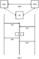
- An exemplary distributed energy conversion system has at least a first energy conversion entity EWE 1 and a second energy conversion entity EWE 2 .
- EWE 1 first energy conversion entity
- EWE 2 second energy conversion entity
- the concept of energy for the modeling in the following includes every carrier, i.e. electrical energy as well as chemically stored energy such as gas or oil, thermal energy, such as geothermal / solar district heating, etc.
- the term energy conversion entity is broadly defined.
- the term includes both energy consumers and energy suppliers.
- Typical energy consumers are “consumption elements" such as engines, while typical energy suppliers are gas generators, electricity generators, and heat generators.
- Storage systems can therefore act both as an energy supplier in the discharge cycle and as an energy consumer in the charge cycle.
- it can be assumed that at a certain point in time when an energy flow occurs, there is at least one consumer and at least one supplier. That is to say, with the invention it is also possible to control different energy sources in a substitute manner for one another. That means, depending on the parameters / data, a certain energy source can make more sense than another at one point in time. The system thus allows unrivaled flexibility.
- the energy can be exchanged between the individual energy conversion entities via one or more energy exchange networks EAN.
- At least one evaluation entity BE is also provided, which can communicate with the energy conversion entities EWE 1 , EWE 2.
- Communication is broadly defined and can include both “internal communication", for example in the case of an integrated structure - more on this later - or more generally also “external communication" with a physically separate unit.
- internal communication for example in the case of an integrated structure - more on this later - or more generally also “external communication” with a physically separate unit.
- the approach described here is due to the underlying logical model. Communication can take place via any suitable medium and is not tied to a specific means of communication. In particular, however, it can be provided that the individual energy conversion entities as well as the evaluation entity BE over the energy exchange network EAN can communicate, for example using technologies such as Powerline.
- first energy conversion entity EWE 1 acts as an energy supply element at a first point in time
- second energy conversion entity EWE 2 acts as an energy consumption element.
- this can be different, as already described, ie the first energy conversion entity EWE 1 act as an energy consumption element at a further point in time and the second energy conversion entity EWE 2 act as an energy supply element .
- the first energy conversion entity EWE 1 provides data relating to the provision of energy to the evaluation entity BE in a step 100, the data comprising one or more of the: availability period, availability amount, costs / energy unit, amount of pollutants / Unit of energy, storage status for one or more future periods.
- the type and selection of the data that can be transmitted is of course dependent on the respective energy conversion entity and / or the carrier used in the energy exchange network.
- the temporal flow rate e.g. m 3 / s
- the flow quantity calorific value / time e.g. kWh / s or kW
- the state number and environmental parameters are known.
- data relating to a period of availability are exchanged, e.g. offer 30 kWh in a period of 1 h with a maximum flow rate of 500 W.
- other data such as measured values on the device, setpoint values of the device, user inputs, etc. can of course also be transferred .
- the second energy conversion entity EWE 2 provides data relating to the purchase and / or use and / or storage of energy to the evaluation entity BE in a step 150, the data having one or more of the following: Acceptance period, acceptance quantity, storage status for one, two or more future periods.
- the type and selection of the data that can be transmitted is of course dependent on the respective energy conversion entity and / or the carrier used in the energy exchange network.
- the temporal flow rate eg m 3 / s
- the flow variable calorific value / time eg kWh / s or kW
- the state number and environmental parameters are known.
- data relating to the acceptance period e.g. required 30 kWh in a period of 1 hour with a maximum flow rate of 500 W, can be exchanged.
- other data such as measured values on the device, user inputs, etc., can of course also be transmitted.
- certain data can of course also be stored in a memory device or database (not shown) and additionally received or queried from the evaluation entity in relation to an energy conversion entity.
- the evaluation entity BE After receiving the data, which of course can arrive at the evaluation entity BE in any order or in parallel, the evaluation entity BE can carry out an evaluation of the data made available in a step 200 in order to create a schedule for the consumption of energy.
- This schedule can then be made available to the participating energy conversion entities EWE 1 , EWE 2 at the same time or one after the other in a step 300 or a step 350.
- the logical functionality of the energy conversion entities EWE 1 , EWE 2 as well as the evaluation entity BE can be implemented, for example, by energy agents that are in the respective "physical" devices, ie the energy conversion entities EWE 1 , EWE 2 is included or is assigned to them. That is to say, to the extent that energy agents are used below, this means an exemplary implementation of the logic concerned.
- the schedule of energy use and provision can now be influenced by influencing the system-inherent parameters of the purchase and / or use and / or storage of energy, for example of the second energy conversion entity EWE 2 , through the schedule will.
- the energy conversion system presented not only allows demand control, but in principle also integrates a generator control.
- the invention thus turns its back on previous systems that have attempted either only by means of demand control or only by means of demand control and allows a far more efficient and complex control not only of one energy source, but also of a large number of energy sources.
- the first energy conversion entity EWE 1 is a power source, for example a wind turbine. This can, for example, provide a certain amount of energy with certain parameters in the time up to sunset, since experience has shown that other energy consumers (e.g. lamps) then take the energy. From midnight, however, the consumption of these consumers decreases, so that the energy is available again for others.
- a power source for example a wind turbine.
- the second energy conversion entity EWE 2 is a washing machine that can spread the individual washing steps over time, for example a first wash cycle at a temperature X corresponding to a first power consumption over a first period of time Z 1 , followed by a spin cycle corresponding to a second power consumption over a second period of time Z 2 , followed by a wash cycle corresponding to a third power consumption over a third period of time Z 3 .
- the evaluation entity BE can now create a schedule with knowledge of this data, for example the period Z 1 should start at the point in time ZP 1 , so that the period Z 1 ends in good time before sunset.
- the spin cycle (second period Z 2 ) can then begin after midnight. This schedule can then be made available to both the EWE 2 washing machine and the EWE 1 wind turbine generator.
- a tumble dryer could be operated with both electricity and waste heat from a solar thermal system.
- the electricity supply as well as the gas supply it can now be decided which energy carrier is used when. For example, at the beginning of a drying process, there can be strong wind, so that there is a high supply of electricity, while a high level of solar irradiation then leads to a corresponding thermal supply.
- the respective energy carrier or the respective usage periods can now be determined depending on the supply and the expected demand.
- the type of energy conversion can be very different.
- the type of energy conversion can be categorized into the following (non-exhaustive) properties: Energy consumption, generation or storage Examples working constantly Light bulbs, devices in standby mode, batteries, special types of (small) power plants tasks dependent White goods (such as washing machines, dishwashers, etc.), Industrial companies (e.g. for start-up and shutdown processes) etc. depending on the environment Wind power and photovoltaic systems repetitive Refrigerators, central heating, ⁇ KWK systems dynamically adjustable Storage power plants, gas power plants, gas turbines, compressors, gas storage, etc.
- Energy flows can depend on external conditions or specific system settings. This applies, for example, to environment-dependent systems such as wind power or photovoltaic systems, which generate energy depending on the current weather conditions and the position of the sun. However, this also applies to dynamically controllable systems that generate or consume energy depending on the corresponding set points.
- Another exemplary task is to transform the individual, system-specific parameters of technical systems into a uniform database in order to be able to determine the resulting energy flows.
- time-dependent energy flows and the resulting amounts of energy form a suitable basis for this, which, however, must be differentiated and evaluated according to the type of energy carrier used, such as electricity or gas. It is crucial that the resulting model is able to map the behavior over time and thus the inherent dynamics of the technical systems.
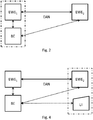
- This logical model can now also be embodied in that the evaluation entity BE, as in Figure 1 represented logically, also physically separated from the energy conversion entities EWE 1 , EWE 2 .
- the evaluation entity can be in its own control center of a house or machine control or it can also be part of so-called smart devices or facilities such as smart meters.
- the evaluation entity BE shown for example, be integrated into the energy conversion entities EWE 1 .
- the data exchange between the logical energy conversion entity EWE 1 ie between the energy agent of the energy conversion entity EWE 1 and the evaluation entity BE can then take place, for example, via an (internal) communication interface.
- the evaluation entity BE is part of the first energy conversion entity EWE 1 and / or part of the second energy conversion entity EWE 2 , because the logical model does not require a clear localization of an evaluation entity.
- an energy conversion entity EWE 1 , EWE 2 can certainly also be connected to several evaluation entities BE and can also exchange data with several evaluation entities BE.
- the evaluation entity can also be made, for example, for the evaluation entity to provide alternatives, ie alternative (execution) timetables. Then it can make sense for the respective energy conversion entity EWE 1 , EWE 2 to decide on the basis of other criteria whether it chooses one or none of the alternatives. This decision can then be communicated to the evaluation entities BE.
- data or information sources for further processing or for controlling a system can be differentiated as follows:
- This type can include the information that can be influenced by an external intervention in the technical system and that thus change the energy flows at the limits of the system.
- these can be the setpoints of the system control, which are generated by an external control unit (such as the energy agent) and can be changed automatically with the aid of appropriate communication protocols.
- an external control unit such as the energy agent
- this type usually cannot allow any changes to be made by an end-user.
- the information that can be changed or specified by an end user can be summarized in this group. This can be, for example, a desired room temperature or a predefined room temperature profile for a day. In contrast to the flexibility information described above, the information in this group cannot initially be changed by automated control processes.
- This group can initially include the system-specific sensor information and thus the measured values that are available on a technical system. This group can also include the current setpoints of the system control and, if there is a related dependency, corresponding information about the surroundings. Typically, read-only access to the information providers and sources is used to record this information.
- topology data and / or system states of the energy exchange network EAN are also made available to the evaluation entity BE, the topology data and / or system states also being taken into account in the evaluation.
- This topology data can either be made available externally (push) and / or from a database DB and / or by means of other services such as a web service - as in Figure 3 indicated - be queried (pull).
- a user of an energy conversion entity can enter data relating to this energy conversion entity EWE 1 , EWE 2 .
- input means that the user specifies the data himself, e.g. a desired setpoint temperature, a desired duration, etc.
- Input includes any form of input, e.g. direct input to the relevant or another energy conversion entity EWE 1 , EWE 2 , a direct input to the evaluation entity BE, or an input via a remote application, for example a telephone app or a web service.
- Such an input can, for example, as in Figure 3 indicated by means of a user interface UI in a step 160. This data can then be taken into account in the same way in the assessment.
- the user interface UI can also be used as in Figure 4 shown as part of an energy conversion entity, here energy conversion entity EWE 1 .
- forecast data is made available externally to the evaluation entity BE in a step 170 (push) and / or from one or more databases DB - as in FIG Figure 3 indicated - be queried (pull).
- forecast data represent information from system variables that have already been defined, directed forward in time.
- the invention offers two options, by way of example, for making forecast data available for the evaluation.
- static forecast measurement series can be stored here.
- cost unit must first be defined, with the help of which these costs are to be summarized. Monetary units come into consideration here. In addition, however, other cost units are also conceivable that can describe the operational use of a system in an equivalent manner. For example, the quantities of carbon dioxide (CO 2 ) produced or saved can be used here, which could be used with appropriately formulated cost functions to evaluate the quantities of energy converted by a technical system accordingly. Cost or conversion units can thus be specified, for example, in “euros per kWh” or in "tons of CO 2 per MWh".
- the amounts of energy converted over time by a technical system can form the basis for its operational evaluation.
- different and sometimes time-dependent cost functions can be used depending on the energy source used and the system-related flow direction. Examples include demand response approaches, the differing rates of remuneration for the extraction or supply of electrical energy to a prosumer, or the connection of a technical system to different networks.
- the system for calculating the costs or income for an operating state defined by the model is designed to combine and add up the partial results of various calculation steps and methods.
- the basis for this can be a description of the state of a technical system, which records the energy-carrier-dependent energy flows at the network connections of a technical system for a defined period of time.
- individually defined cost functions can be used to evaluate the price of the energy turnover in an operating state.
- the sum of the expenses or income related to the energy flows can represent the first aspect for the operational evaluation of individual, time-limited operating and system states.
- forecast data relating to at least one of the energy conversion entities EWE 1 , EWE 2 are made available to the evaluation entity BE, the data having one or more of the following: energy generation or use, storage volume and state for one or more future time periods.
- both the time spans to be considered and the evaluation criteria for the amount of energy converted can differ.
- both short-term decisions e.g. for the "fast" stabilization of a local network in the seconds and minutes range
- medium and long-term plans that extend over a period of several hours or days.
- the model can support the pursuit of different objectives.
- certain information that can be used in the context of a state space evaluation can be advantageous. In accordance with the objectives made possible by the invention, this particular information is identified and briefly explained below:
- the invention offers the information required for this about the input and output information, the basic model and the possibility of describing the state of a technical system over time. With the help of the accumulated energy expenditure, the amount of energy transported at an interface and over time can be updated. In addition to this, the energy loss that results from the current efficiency of a system can also be of interest. For this purpose, there is also the option of adding up these values over time in the course of the evaluation process. Analogous to the explanations about the short-term stabilization of system connections, forecasts of measurement and default values can also be advantageous for these optimization goals.
- This optimization goal too, first of all requires a consideration of the current operating status and a determination of the amounts of energy that have accumulated over time.
- an optimization geared towards costs additionally requires the definition of a suitable cost model that summarizes the amounts of energy consumed or generated over time with the aid of suitable cost functions under a common cost unit. Analogous to forecast values, this information can also be available for the optimization period under consideration and can also change over time.
- evaluation unit BE can also pursue more than one goal, it being possible for the goals to be weighted, which in turn can be dependent on user specifications or other parameters.
- step 200 If the evaluation process in step 200 is viewed as a forward-looking, systematic search for an optimized schedule, the most varied of states of a technical system can be determined with the aid of the time steps described by the operating states.
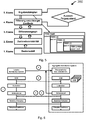
- the first level represents a basic model that can include all parameters describing the system. This can include the internal and external information sources mentioned as well as connection configurations, network connections, energy carriers involved, operating states, operating state transitions and energy-carrier-dependent energy flows, etc. All other levels use the information provided here.
- the second level offers answers regarding the possible flexibility of a technical energy conversion process. Depending on the current state of a system, this can answer the question of which system states could be set as subsequent states by definition.
- the system can provide a search graph that makes it possible to map the state space that has already been determined and to reuse determined energy flows and the corresponding costs.
- the fourth level offers support with regard to time restrictions as well as possible storage states, so that the final, fifth level can represent the completed result schedules. The levels, which are only briefly described here, are explained in more detail below.
- G ZV (V, E) describes a directed graph for the state variability of a technical system, where the node V describes the finite set of all operating state and setpoint-dependent states of a system and E, the edges of the graph, the finite set of all possible Transitions between these states.
- the initial state of the system defined for the evaluation is first used to create the first node of the graph.
- possible subsequent states are then determined. It should be noted that a variation of setpoints can lead to a multiplication of the possible subsequent states.
- the possible subsequent values can easily be determined for individual target values. In the combination of several setpoints, however, the total amount of possible subsequent states results from the cross product of all individual setpoint variations.
- the subsequent states Once the subsequent states have been determined for a state, corresponding nodes are created for this. This procedure can then be applied recursively to one or more subsequent states until the associated operating state and setpoint variations of the technical system have been determined and mapped.
- a simple hash process can be used, which uses the current operating status and the current setpoint values as a basis. The resulting number of nodes is highly dependent on the system under consideration, but does not pose any major challenges in terms of memory load or performance. In the next level of the basic system, however, it can save the need to re-instantiate and carry out the procedure described here for determining subsequent states.
- the solution approach designed for this problem is addressed by the third level of the basic system described here.
- the basis for this is the already described clear identification of the state of a technical system.
- This can be used at this level to build a difference graph that describes the possible states of a technical system over time.
- the nodes of this graph can contain the temporal system states with all input and output values as well as the energy flows present at the network connections of the technical system at this point in time.
- the initial or initial state can first be identified. In a real system, this can be done, for example, by recording current measured values and energy flows. In the context, this is generally specified by the settings in preparation for the evaluation. With the defined initial status, a complete and precise description of all status values is available. This can include (all) input and output information (including updated forecast values), all energy flows present at the specific point in time at the connection points and, if available, the storage states of the energy storage devices in the system. Cumulative amounts of energy, resulting costs and energy flows are 0 at this point in time.
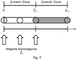
- the model can, for example, at the same time also describe the time period for an operating state for which it is defined.
- the specific starting time for an initial state Z S can be, for example, directly at the beginning, in the middle or at the end of a defined operating state, see in this regard Figure 7 .
- the resulting state Z i + 1 thus represents the first state in which a decision regarding the flexibility of a system can be made.
- the task of the edges of the graph is to describe the changes that are produced by a selected subsequent state. Based on the duration and the energy flows of an operating state (including losses), these changes can initially include the amounts of energy that are transferred via the individual network connections of the technical system. This can also include the energy carrier-dependent costs or income generated. Based on this, the determine the further course of the balanced resulting energy turnover and the corresponding change in relation to the total costs.
- the calculation steps used here essentially correspond to the method presented in the context of the cost model for determining the total costs, but according to the model assumptions can only apply to a selected operating state and a variant of the possible target value combinations. In addition, the information about the converted energy flows and quantities can be retained for reuse.
- the difference graph does not generally have to be created. Rather, it can be used, for example, if the basic system of the energy option model described here is applied. However, the graph is not created directly and in full over the entire evaluation period, but can only be created at the points where a search process is currently located. Starting from a previous state, the graph of the state variability can initially be used to determine all possible changes for the operating state and setpoint values. Based on this, all of the changes that correspond to this, as well as the resulting subsequent states, can then be determined. There is no need to expand the graph behind unvisited nodes or system states.
- the difference graph can already take concrete system states into account, but it only focuses on the energy flows at the limits of a technical system. This results from the approach to the unambiguous identification of a system state, which also makes the nodes identifiable in the difference graph.
- the system parameters can be specified that have a direct or indirect influence on the energy flows at the limits of the technical system.
- the specific memory states of a technical system have not yet been taken into account. Furthermore, the time restrictions that can be defined with minimum and maximum dwell times for individual operating states have not yet been taken into account. In addition, the control values controlled by the controller of a system should also be kept within the specified limits.
- the outgoing edges of the difference graph can be used to check how large possible changes can be in relation to the fill levels of a memory. If the status resulting from a change is less than 0 or greater than the specified storage capacity, this subsequent status is excluded from further considerations.
- the monitoring and filtering to comply with the minimum and maximum time restrictions for an operating state may require the prior operating states to be taken into account.
- For the minimum duration an operating state may only be exited if the defined minimum dwell time has been exceeded. Accordingly, the decision as to which subsequent state may be adopted at a specific point in time can depend on this. If the defined minimum time in the series of previous states has not yet been reached, this reduces the list of possible next operating states accordingly.
- For the maximum duration an operating state should be exited when the maximum period of time for an operating state is exceeded.
- a backward-looking search process can be used to check this restriction and to reduce the list of possible subsequent states if necessary.
- the last aspect, which can be checked in the 4th level, is the regulation of the technical system, given limit values of specific measured values. If a calculated new measured value exceeds or falls below the specified control range, the new system status resulting from the changes can be filtered out.
- the result of an evaluation and thus the schedule for a technical system is represented in the model by the state that was determined for the end of the evaluation period.
- the system states upstream in time can be stored recursively.
- a subsequent state can thus be determined or selected step by step.
- the reference to the current status can then be saved in the storage of the subsequent status.
- the evaluation run can be continued in this way.
- the search for creating an individual schedule in step 200 can proceed in such a way that, based on the initially defined system state, which can be within the period of an operating state, it can first be ensured that this is calculated until the end of the operating state will. This means that the converted energy quantities and costs are determined up to the end of the current operating state and thus the first edge in the difference graph is also generated.
- the subsequent node and the state of the technical system that corresponds to it represent the starting point for the cyclical search process that uses the described auxiliary levels 2 to 4 for this purpose.
- the difference graph can be used to query which variation of subsequent statuses exist for the current system status. If these have not yet been determined for the requested time and the associated system status, they can be generated on request.
- the graph of the state variability can first be used to determine which changes are possible in relation to operating states and setpoints by definition in the basic model. From this, the possible changes in relation to energy flows and quantities, the corresponding costs and the subsequent states can be determined - the latter can be mapped at the same time by new nodes in the difference graph.
- the 4th level of the basic system can check and filter the admissibility of the possible changes.
- the subsequent states identified by the difference graph can be checked with regard to memory states and time restrictions to be observed, so that only validated and applicable subsequent states are returned to the result level. After that it can be the job of one Decision-making process to determine the next system state.
- the Figure 5 graphically depicts the context of the assessment in step 200 as well as a structural structure of a result timetable, whereby the result timetable is then in the context of the assessment as TSSE (final) from the intermediate timetables TSSE (initial), TSSE (2nd level) determined in each case ) ... TSSE (4) results.
- step 200 it is also possible to parallelize the partial steps within step 200.
- the sub-steps and levels presented are only examples of a model.
- the parallelization of evaluation strategies which is basically possible by executing several evaluation threads, can also be implemented for the step-by-step basic system presented here.
- the simultaneous creation of nodes for a system state is the main problem, as it can lead to inconsistent or even overwritten node instances within the graph.
- a locking procedure was developed that prevents the simultaneous creation of nodes for one and the same system state.
- the simultaneous creation of state nodes can be prevented.
- the created node can be assigned a lock that can only be released again by the thread creating the node.
- the model enables several systems to be viewed at the same time.
- the system concept and thus the encapsulation of individual systems is used as the basis for describing a system of systems.
- the aggregation itself can represent its own system, while all subsystems to be taken into account can still be handled in the manner described above. Any complex combinations of systems can thus be configured, for example as a tree-like structure, in which individual systems are used in the form described above or can be represented by alternative or individual timetables.
- the concept of the step-by-step approach to evaluating individual systems can be expanded and adapted will.
- network status calculations can be carried out within the framework of the application of an individual evaluation strategy. Analogous to individual systems, individual strategies can also be developed and implemented here.
- the model is also suitable for add-hoc decision-making processes that can be used, for example, in the area of technical control.
- the continuously updated system states of the systems involved can be used to determine current options for action for each energy conversion process.
- An evaluation process based on the current time could run ahead of the current time and pre-evaluate the possible subsequent states. Since these evaluation results are stored in the difference graph of the relevant system, this also leads to an accelerated response time behavior, which is of enormous importance for time-critical applications.
- One aim of the invention is to first describe the flexibility of a technical one and to make it usable or controllable in the sense of a higher-level objective.
- the structure of the model enables the description of any energy conversion processes as well as the consideration of different energy sources, such as electricity and natural gas.
- This hybrid approach is not limited to the mapping of the existing flexibility in terms of operating states, setpoint variations and the resulting energy flows, but rather supports the development of new, as yet non-existent operating and system states.
- the point of contact for the control of individual technical systems is thus initially the information technology interface that is offered by the control of a system.
- One aim of the invention is to be able to functionally map the relationship between this information and the corresponding energy flows in order to be able to serve as a basis for realistic and thus reliable forecasting, monitoring and optimization processes.
- So-called system variables are defined in the model as a description of the measured values, control setpoints and user specifications available on the system.
- the model also allows the definition of static data models and the definition of system variables that cannot be determined directly on the technical system, but only via external information services. In this way, for example, static maps of systems on the one hand or external weather information on the other hand can be defined and used in the energy option model. All system variables together serve the purpose of describing the basic, input and output information that influences the energy flows occurring in an energy conversion process.
- the basic model of the model of the invention includes first of all the definition of the system boundaries that connect a single system with one or more energy networks and the corresponding energy sources, as well as the possible connection variations.
- the different connection options of an electric car can be described (see e.g. IEC 62196 ) or the different ways of using a system (e.g. for different programs for white goods devices).
- the modeling of the operating states of a system can be made possible by a directed graph.
- the nodes of the graph represent the individual, time-limited operating states, while the directed edges describe the possible sequence of these states.
- the length of stay in an operating state can also be limited, for example to protect a system or to take into account the memory status of a system.
- corresponding energy flows can be defined for each operating state.
- functions for the minimum and maximum dwell time in an operating state possible energy flow gradients or calculation methods that can be used to determine loss energies can be defined.
- temporal system states are first defined, which at the same time define the evaluation period to be considered.
- forecast functions for the period under consideration can be defined in different ways. In this way, for example, weather information can be made available for the period under consideration, which can be used in the context of corresponding calculations to determine the amount of electricity produced by a photovoltaic system.
- the model also offers an open approach for evaluating the operational use of energy conversion processes.
- individual cost functions can be defined, which on the one hand can evaluate the energy flows occurring in the system, but on the other hand also the specific operating states of a system. This can be used, for example, to define evaluation parameters in € / kWh or kg - CO 2 / MWh , which can be applied to the specific conditions, performance parameters and time periods as part of the system evaluation.
- the model In addition to using the open interface to create a system timetable, the model also offers a special, step-by-step procedure for generating timetables, which can also be used as part of individual evaluation strategies.
- mapping the system states in a difference graph system states and possible subsequent states can be mapped.
- control decisions can be qualified by quantifying parameters such as performance and storage sizes, which makes making control decisions well-founded and thus considerably simpler.
- a detailed result schedule can be made available, which can represent a detailed description of the temporal system states. This can contain both the basic, input and output information of the system, as well as the resulting energy flows, which can depend on these parameters.
- the result schedule can also represent a serializable element so that it can be communicated via an exchange of messages if necessary.
- the model of the invention enables the simultaneous consideration of several technical systems that represent a grid-connected energy conversion process.
- the system concept and thus the encapsulation individual systems are used as the basis to describe a system of systems.
- the aggregation itself can represent its own system, while all subsystems to be taken into account can still be handled in the manner described above. Any complex combinations of systems can thus be configured as a tree-like structure in which individual systems are used in the form described above or can be represented by alternative or individual timetables.
- the concept of the step-by-step approach to evaluating individual systems can be expanded and adapted.
- network status calculations can be carried out within the framework of the application of an individual evaluation strategy. Analogous to individual systems, however, individual strategies can also be developed and implemented here. The flexibility resulting from the approach with regard to the location of decision-making processes was made possible by Figure 6 . presented.
- the data in a certain structure, for example an XML format.
- techniques such as SOAP or REST can also be used to query data.
Description
Die Erfindung betrifft ein verteiltes Energie-Wandlungs-System.The invention relates to a distributed energy conversion system.
Die Erzeugung, Verteilung und der Verbrauch unterschiedlicher Energieträger ist bekannt. Allerdings werden die Erzeugung, die Verteilung und auch der Verbrauch zunehmend komplexer.The generation, distribution and consumption of different energy sources is known. However, generation, distribution and consumption are becoming increasingly complex.
Beispielsweise kann es durch die zunehmende Verwendung volatiler Energieerzeugungsanlagen (am Beispiel der Stromerzeugung), wie beispielsweise Wind- oder Photovoltaik-Anlagen, zu einer Über- oder Unterproduktion elektrischer Energie kommen, die durch die Kapazität oder die Speicherfähigkeit eines elektrischen Netzes nicht abgedeckt werden kann. Dieses Problem wird häufig als Speicherlücke des elektrischen Netzes bezeichnet.For example, the increasing use of volatile energy generation systems (using the example of electricity generation), such as wind or photovoltaic systems, can lead to an over- or under-production of electrical energy that cannot be covered by the capacity or storage capacity of an electrical network. This problem is often referred to as an electrical network memory gap.
Um diesem zu begegnen werden sogenannte "Smart Grids" vorgeschlagen. Die Vielzahl der aktuellen Smart Grid-Anwendungen und Entwicklungen konzentrieren sich in diesem Zusammenhang im Wesentlichen auf die alleinige Kontrolle von elektrischer Energieerzeugung und -verbrauch.So-called "smart grids" are proposed to counter this. In this context, the large number of current smart grid applications and developments essentially focus on the sole control of electrical energy generation and consumption.
Im technisch übergeordneten Bereich (elektrisch) liegt das Hauptaugenmerk der Kontrollaufgaben auf der Frequenzhaltung, um die Stabilität der Netze gewährleisten zu können, während im Mittel- und Verteilnetzbereich auf die Einhaltung von Spannungsbändern fokussiert wird, sodass es nicht zu ungewollten Über- oder Unterspannungen bei den Verbrauchern kommt, die hierdurch geschädigt werden könnten. Hinzu kommen in der Regel ökonomische Aspekte, die eine Kontrolle von Energieerzeugung und -verbrauch (inklusive Speicherung) unter Marktaspekten vorsehen, wie z.B. im Bereich der Regelenergie oder bei der Einhaltung vertraglich zugesicherter Abgabe- oder Verbrauchsmengen.In the technically higher-level area (electrical), the main focus of the control tasks is on maintaining the frequency in order to be able to guarantee the stability of the networks, while in the medium and distribution network area the focus is on maintaining voltage ranges so that there are no unwanted overvoltages or undervoltage in the Consumers who could be harmed as a result. In addition, there are usually economic aspects that provide for a control of energy generation and consumption (including storage) under market aspects, such as in the area of control energy or compliance with contractually guaranteed delivery or consumption quantities.
Weitere Schwerpunkte die eine Kontrollbasis für Energiewandlungs- und Speichersystemen darstellen können, sind Aspekte wie die energieeffiziente Nutzung eines Systems, die Reduktion von Umweltbelastungen (z.B. CO2-Emmissionen) u.a.Other focal points that can represent a control basis for energy conversion and storage systems are aspects such as the energy-efficient use of a system, the reduction of environmental pollution ( e.g. CO 2 emissions) and others
Aktuelle Entwicklungen im Bereich der sog. Smart Grids fokussieren auf zentral ausgerichtete Kontrollstrukturen. Damit sind solche Kontrollstrukturen gemeint, in denen eine Reihe räumlich verteilter Systeme durch ein Kommunikationsnetzwerk verbunden werden, um von einem zentralen Punkt aus alle notwendigen Kontrollentscheidungen für die beteiligten Systeme zu treffen.Current developments in the area of so-called smart grids focus on centrally aligned control structures. This means control structures in which a number of spatially distributed systems are connected by a communication network in order to make all the necessary control decisions for the systems involved from a central point.
Ein Kontrollansatz dabei ist z.B. eher planerischer Natur. Andere, alternative Kontrollansätze betreffen eher kurzfristige bzw. Realtime Kontrolle.A control approach is, for example, more of a planning nature. Other, alternative control approaches relate more to short-term or real-time control.
Aus dem Stand der Technik sind konventionelle Energie-Wandlungs-Systeme bekannt.Conventional energy conversion systems are known from the prior art.
Dabei kann als eine Grundannahme angenommen werden, dass alle Energie-Wandlungs-Systeme auf dem ersten Hauptsatz der Thermodynamik und dem Energieerhaltungssatz basieren. Demnach werden spezifische Energieformen in technischen Systemen immer nur umgewandelt, eine Bilanzierung der dem System zu- und abgeführten Energiemengen ist stets 0.It can be assumed as a basic assumption that all energy conversion systems are based on the first law of thermodynamics and the law of conservation of energy. According to this, specific forms of energy are only ever converted in technical systems, a balance of the amounts of energy supplied to and removed from the system is always 0.
Eine Vielzahl bisheriger Energie- bzw. Lastmanagementsysteme erlauben zwar eine zentral organisierte Energiefluss-Optimierung verteilter Systeme, eine übergeordnete und wahlweise zentral oder verteilt organisierte Optimierung von unterschiedlichen Energieformen, Energieträgern, Energiequellen und Energiesenken ist mit den bisherigen Ansätzen jedoch nicht oder nur unzureichend möglich.Although a large number of previous energy and load management systems allow a centrally organized energy flow optimization of distributed systems, a higher-level and optionally centrally or distributed optimization of different forms of energy, energy carriers, energy sources and energy sinks is not or only inadequately possible with the previous approaches.
Aus der US Patentanmeldung
Allerdings ist das Lastmanagement nur unzureichend geeignet die Herausforderung der Steuerung unterschiedlicher Energieträger in effizienter Weise bereitzustellen. Ähnliches gilt auch für das Erzeugersteuerungssystems.However, the load management is only insufficiently suited to the challenge of controlling different energy sources in an efficient manner. The same applies to the producer control system.
Aus der
Das System erweist sich jedoch als unflexibel und erlaubt nur in engen Grenzen eine Änderung des Netzes. Aufgrund der notwendigen Benutzereingriffe stellt sich das System als umständlich heraus. Zudem stellt sich das System insbesondere für dynamische Wechsel der Nachfrage und/oder des Angebotes als problematisch dar, da es ausschließlich auf Kosten basiert.However, the system proves to be inflexible and only allows changes to the network within narrow limits. Due to the necessary user interventions, the system turns out to be cumbersome. In addition, the system is particularly suitable for dynamic changes the demand and / or the supply is problematic because it is based solely on costs.
Die bisherigen zentralen Ansätze weisen Nachteile auf, die im Folgenden kurz skizziert werden sollen. So sind die bisherigen Kontrollansätze nicht Ausfall- oder Fehlertolerant. Insbesondere kann z.B. der (Teil-) Ausfall der Datenkommunikation zu einem Kontrollverlust über die beteiligten (Teil-) Systeme führen (single point of failure). Zudem steig mit der Anzahl der zu kontrollierenden Systeme die Komplexität der Kontrollaufgaben, die kaum oder nicht mehr zu beherrschen ist. Dabei ist festzustellen, dass der notwendige Datenverkehr zunehmend steigt und neben Kapazitätsproblemen auch zu einer zunehmenden Nutzung von Energie für die Kommunikation und die Verarbeitung der Daten führt. Somit ist insbesondere bei großen Anlagenaggregationen eine Echtzeit-Steuerung nicht mehr möglich. Korrespondierend hierzu steigt der Investitionsbedarf in die Datenübertragung- / Datenverarbeitungsinfrastruktur.The previous central approaches have disadvantages, which are briefly outlined below. So the previous control approaches are not failure or fault tolerant. In particular, the (partial) failure of data communication can lead to a loss of control over the (partial) systems involved (single point of failure). In addition, with the number of systems to be controlled, the complexity of the control tasks, which can hardly or no longer be controlled, increases. It should be noted that the necessary data traffic is increasing and, in addition to capacity problems, also leads to an increasing use of energy for communication and processing of the data. This means that real-time control is no longer possible, especially with large system aggregations. Correspondingly, the need for investment in the data transmission / data processing infrastructure increases.
Zudem fehlt es aktuellen Kontrollansätzen an einer grundsätzlichen, automatisierbaren Adaptivität. Damit ist die Fähigkeit gemeint, ein zu kontrollierendes Energiewandlungssystem dynamisch unter die Kontrolle einer kontrollausübenden Einheit zu stellen (z.B. im Rahmen der Systemaggregation in einem verteilten virtuellen Kraftwerk), ohne dass das kontrollausübende System das konkret einzubindende System vorab "kennen" muss. Die Ursachen hierfür sind, dass für die Ausübung der Kontrolle (Informationsaustausch in Bezug auf Systemzustände / Messwerte, Übergabe von Vorgabewerten an ein System) in aller Regel auf Grundlage spezifischer, ggf. anwendungsbezogener und z.T. standardisierter Protokolle erfolgt (z.B. Modbus RTU, Profibus, OPC UA, MBus, EEbus, IEC 61850, IEC 60870 u.v.m.). In ihrer Form fokussiert ein Teil der genannten Protokolle lediglich auf eine serielle Übertragung von Mess- und Vorgabewerten. Dies erfordert sowohl bei den Sendern, als auch bei den Empfängern von Nachrichtenpaketen eine Abstimmung und Konfiguration in Bezug auf die Reihenfolge und das Format der übertragenen Informationen. Andere der genannten Protokolle stellen einen Standard für die Kommunikation in spezifischen Anwendungsgebieten dar, wie z.B. die IEC 60870-5-104 ("Anwendungsbezogene Norm für Fernwirkaufgaben in IP-Netzen"), das im Rahmen der Fernwirktechnik im Bereich der Infrastrukturautomation eingesetzt wird. Auch hier erfolgt in der Regel eine individuelle Konfiguration, so dass wiederum Sender und Empfänger von Nachrichten aufeinander abgestimmt werden müssen.In addition, current control approaches lack a fundamental, automatable adaptivity. This means the ability to dynamically place an energy conversion system to be controlled under the control of a unit exercising control (e.g. within the framework of system aggregation in a distributed virtual power plant) without the system exercising control having to "know" the specific system to be integrated in advance. The reasons for this are that the exercise of control (exchange of information with regard to system states / measured values, transfer of default values to a system) is usually based on specific, possibly application-related and partly standardized protocols (e.g. Modbus RTU, Profibus, OPC UA, MBus, EEbus, IEC 61850 , IEC 60870 and many more). In terms of their form, some of the protocols mentioned focus only on the serial transmission of measurement and default values. This requires both the senders and the recipients of message packets to coordinate and configure the sequence and format of the information transmitted. Others of the protocols mentioned represent a standard for communication in specific application areas, such as IEC 60870-5-104 ("Application-related standard for telecontrol tasks in IP networks"), which is used in the context of telecontrol technology in the field of infrastructure automation. Here, too, there is usually an individual configuration so that the sender and recipient of messages have to be coordinated with one another.
Im standardisierten, wie auch im nicht standardisierten Fall kann eine Kontrollaufgabe (z.B. zur Optimierung) demnach nur dann erfolgen, wenn die entsprechenden Parameter an der kontrollausübenden Einheit bekannt und entsprechend übersetzt werden. Darüber hinaus muss die Art des zu kontrollierenden Systems und die damit im Grundsatz verbundenen Flexibilisierungsmöglichkeiten in Bezug auf Energieerzeugung, -verbrauch und -speicherung bekannt sein, so dass diese entsprechend der Zielvorgaben gesteuert werden können.In the standardized as well as in the non-standardized case, a control task (e.g. for optimization) can therefore only be carried out if the corresponding parameters are in the unit exercising control are known and translated accordingly. In addition, the type of system to be controlled and the flexibility options associated with it in terms of energy generation, consumption and storage must be known so that these can be controlled in accordance with the target specifications.
Aktuelle Kontrollansätze erfordern hierzu einen nicht unerheblichen, manuellen (und somit im Sinne der Erfindung nicht adaptiven) Konfigurationsaufwand, der in der Regel in Bezug auf die Systemzusammensetzung statisch ist.Current control approaches require a not inconsiderable, manual (and thus not adaptive in the sense of the invention) configuration effort, which is usually static with regard to the system composition.
Es ist daher Aufgabe der Erfindung ein verbessertes verteiltes Energie-Wandlungs-System und dessen Komponenten bereitzustellen, das/die einen Nachteil oder mehrere Nachteile aus dem Stand der Technik vermeiden.It is therefore the object of the invention to provide an improved distributed energy conversion system and its components which avoid one or more disadvantages from the prior art.
Die Aufgabe wird gelöst durch ein verteiltes Energie-Wandlungs-System gemäß Anspruch 1. Vorteilhafte Ausgestaltungen der Erfindung sind in den Unteransprüchen angegeben.The object is achieved by a distributed energy conversion system according to
Nachfolgend wird die Erfindung unter Bezugnahme auf die anliegende Zeichnung anhand bevorzugter Ausführungsformen näher erläutert.The invention is explained in more detail below with reference to the attached drawing on the basis of preferred embodiments.
- Fig. 1Fig. 1
- eine schematische Darstellung von Ausführungsformen der Erfindung nebst einem typischen Kommunikationsablauf,a schematic representation of embodiments of the invention along with a typical communication sequence,
- Fig. 2Fig. 2
- eine weitere schematische Darstellung von Ausführungsformen der Erfindung,a further schematic representation of embodiments of the invention,
- Fig. 3Fig. 3
- eine zweite weitere schematische Darstellung von Ausführungsformen der Erfindung,a second further schematic representation of embodiments of the invention,
- Fig. 4Fig. 4
- eine dritte weitere schematische Darstellung von Ausführungsformen der Erfindung,a third further schematic representation of embodiments of the invention,
- Fig. 5Fig. 5
- eine mögliche Modellierung von Bewertungsebenen in einer Ausführungsform der Erfindung,a possible modeling of assessment levels in one embodiment of the invention,
- Fig. 6Fig. 6
- Varianten von Einsatzmöglichkeiten der Erfindung, undVariants of possible uses of the invention, and
- Fig. 7Fig. 7
- Zusammenhänge zwischen Zuständen und Folgezuständen gemäß einer Ausführungsform der Erfindung.Relationships between states and subsequent states according to an embodiment of the invention.
Soweit nachfolgend in der Beschreibung der Figuren "ein" verwendet wird ist damit der unbestimmte Artikel jeweils gemeint und keine Festlegung auf genau einen Gegenstand. D.h. soweit nicht explizit angegeben ist mit "ein" auch immer der Plural umfasst.Insofar as "a" is used in the description of the figures below, this refers to the indefinite article in each case and does not refer to exactly one object. That is, unless explicitly stated, "a" always includes the plural.
Soweit nachfolgend Aspekte der Erfindung beschrieben werden, können diese wechselseitig in den unterschiedlichen Ausführungsformen verwendet werden, soweit nicht explizit nur als Alternative dargestellt.Insofar as aspects of the invention are described below, these can be used alternately in the different embodiments, unless explicitly shown only as an alternative.
Im Gegensatz zu bekannten Energie-Managementsystemen, die aufgrund Ihrer zentral ausgerichteten Kontrollstrukturen mit einem großen und kostenintensiven Systemaufbau und entsprechend vielen Teilkomponenten versehen werden müssen, erlaubt die Erfindung ein kompaktes, softwaretechnisches, standardisiertes, umfassendes, adaptives und kostengünstiges System zur Verfügung zu stellen, dass in der Lage ist, zunächst einzelne hybride (multimodale) Energiewandlungsprozesse zu steuern und dabei zusätzlich individuelle Optimierungsaufgaben zu erfüllen.In contrast to known energy management systems, which have to be provided with a large and cost-intensive system structure and a corresponding number of sub-components due to their centrally aligned control structures, the invention allows a compact, software-based, standardized, comprehensive, adaptive and cost-effective system to be made available that is able to initially control individual hybrid (multimodal) energy conversion processes and additionally to fulfill individual optimization tasks.
Auf Grundlage eines generellen, leistungs- und energiemengen-orientierten Ansatz kann die Erfindung sowohl für elektrische Energie, aber auch für andere Energieträger und -formen eingesetzt werden können. Hierdurch wird es ermöglicht, dass energieträgerübergreifende (multimodale) Flexibilisierungsmerkmale von Energiewandlungssystemen genutzt werden können, um unterschiedlichste Kontrollanforderungen und Ziele erfüllen bzw. erreichen zu können (technisch, ökonomisch oder ökologisch).On the basis of a general, performance and energy quantity-oriented approach, the invention can be used not only for electrical energy, but also for other energy carriers and forms. This enables cross-energy (multimodal) flexibility features of energy conversion systems to be used in order to meet or achieve a wide variety of control requirements and goals (technically, economically or ecologically).
Durch eine einheitliche Beschreibung von Systemen, der Möglichkeit diese Beschreibung in Form einzelner Beschreibungsdateien zu speichern und somit automatisiert austauschen zu können, wird eine grundlegende Adaptivität bereitgestellt, die es erlaubt unterschiedlichste Energiewandlungsprozesse und Systeme miteinander zu kombinieren, ohne das die energietechnischen Fähigkeiten einzelner System a priori in ein (zentrales) Energiemanagementsystem integriert werden müssen.A uniform description of systems, the possibility of saving this description in the form of individual description files and thus being able to exchange them automatically, provides a basic adaptivity that allows a wide variety of energy conversion processes and systems to be combined with one another without the a priori of the energy-related capabilities of individual systems must be integrated into a (central) energy management system.
Die Erfindung ermöglicht zudem, dass einzelne oder mehrere Systeme dynamisch in Aggregationen eingefügt oder entfernt werden können (z.B. innerhalb eines virtuellen Kraftwerks oder innerhalb sog. "Smart House"-Anwendungen).The invention also enables individual or multiple systems to be dynamically inserted or removed from aggregations (e.g. within a virtual power plant or within so-called "smart house" applications).
Durch die einheitliche bzw. gleichartige Beschreibung von Energiewandlungssystemen durch die Erfindung wird ein Kontrollansatz geboten, der es erlaubt einen Energiewandlungsprozess vollends selbstbeschreibend zu machen. Dabei können die Variations- und Flexibilisierungsoptionen, die ein Energiewandlungsprozess bietet, auf gleichartige Parameter reduziert werden, die sich im Wesentlichen auf eine systematische Auswahl von Betriebszuständen und der konkreten Anwendung sog. Sollwertvariationen beschränken. Dabei können die hieraus resultierenden Systemzustände mit Hilfe der Erfindung sowohl energetisch qualitativ, als auch quantitativ beschrieben werden. Darauf basierend und unabhängig vom zu steuernden System, können darüber hinaus mithilfe von Bewertungs- oder Kostenfunktionen übergeordnete Optimierungsalgorithmen und -ansätze entwickelt werden, die sogar unabhängig vom konkreten Energiewandlungsprozess bzw. -system sein können.The uniform or similar description of energy conversion systems by the invention provides a control approach that allows an energy conversion process to be made completely self-describing. The variation and flexibility options that an energy conversion process offers can arise Similar parameters are reduced, which are essentially limited to a systematic selection of operating states and the specific application of so-called setpoint variations. The system states resulting from this can be described both energetically, qualitatively, and quantitatively with the aid of the invention. Based on this and independent of the system to be controlled, overarching optimization algorithms and approaches can also be developed with the help of evaluation or cost functions, which can even be independent of the specific energy conversion process or system.
Die Erfindung erlaubt aber auch die betrachteten Einzelsysteme oder auch Aggregationen von mehreren Einzelsystemen einer neuen organisatorischen Zugehörigkeit zur Verfügung stellen zu können. D.h., die Erfindung ermöglicht es, dass energiekonsumierende Systeme einerseits einem neuen Lieferanten dynamisch zugeordnet oder das energieproduzierende Systeme in die Planung eines Lieferanten dynamisch mit einbezogen werden können. Darüber hinaus können gleichfalls netzdienliche Systemeigenschaften ermittelbar sein, so dass unter Umständen verfügbare, netzstabilisierende Dienstleistungen von Systemen der organisierenden Einheit des Netzbetriebs zur Verfügung gestellt werden können.However, the invention also allows the individual systems under consideration or also aggregations of several individual systems to be made available to a new organizational affiliation. That is, the invention enables energy-consuming systems to be dynamically assigned to a new supplier on the one hand, or energy-producing systems to be dynamically included in the planning of a supplier. In addition, system properties that are useful for the network can also be determined so that network stabilizing services that are available under certain circumstances can be made available by systems of the organizing unit of network operation.
Auf Basis des atomaren bzw. singulären Modellierungs- und Steuerungsansatz, der durch die Erfindung ermöglich wird, kann der Modellierungs- und Steuerungsansatz nicht nur im Bereich von parallel geführten Systemen zum Einsatz kommen, wie es z.B. im Bereich der elektrischen Stromversorgung der Fall ist, bei der z.B. Kontrollentscheidung in der Regel zeitlich parallel getroffen werden, so dass spezifische, zeitabhängige Kontrollziele verfolgt werden können (Stabilität, Energieeffizienz, Kostenoptimierung u.a.).Based on the atomic or singular modeling and control approach made possible by the invention, the modeling and control approach can not only be used in the area of parallel systems, as is the case, for example, in the area of electrical power supply The control decision, for example, is usually made at the same time, so that specific, time-dependent control objectives can be pursued (stability, energy efficiency, cost optimization, etc.).
Im Gegensatz hierzu erlaubt es die Erfindung auch sequentiell betriebene Systemkonstellationen beschreiben und steuern zu können. Derartige Problemstellungen finden sich beispielsweise in industriellen oder verfahrenstechnischen Prozessen sowie im Bereich von Gas- und Wärmenetzen, bei denen der Zustand vorgelagerter Systeme direkte Auswirkungen auf die folgenden Systeme haben.In contrast to this, the invention also allows sequentially operated system constellations to be described and controlled. Such problems can be found, for example, in industrial or process engineering processes as well as in the area of gas and heating networks, in which the state of upstream systems has a direct impact on the following systems.
Durch die Möglichkeit verschiedene sog. Evaluationsstrategien zeitgleich und kompetitiv zueinander für ein einzelnes System Vorort auszuführen, können bereits Einzelsysteme dazu befähigt werden, um in einer "intelligenten" und flexiblen Weise auf verschiedenartige Optimierungsanforderung hin zu operieren. Die durch die Erfindung generierten Fahrplanalternativen können von den vor Ort eingesetzten Softwarekomponenten (z.B. von sog. Energie-Agenten) dazu genutzt werden, um aus den verschiedenen Möglichkeiten die situativ beste Alternative zu wählen.Due to the possibility of executing different so-called evaluation strategies simultaneously and competitively with one another for a single system on site, even single systems can be enabled to operate in an "intelligent" and flexible manner on different optimization requirements. The alternative schedules generated by the invention can be used by the software components used on site (e.g. by so-called energy agents) in order to choose the best alternative for the situation from the various options.
Durch das durch die Erfindung bereitgestellte Wissens- und Handlungsmodel in Bezug auf einzelne Energiewandlungsprozesse und -systeme, wird gleichfalls eine künstliche Beschreibung geschaffen, die auch außerhalb realer Systemumgebungen verwendet werden kann. So erlaubt es die Erfindung im Rahmen von dynamischen Simulationen ein entsprechendes Modell eines Systems zur Verfügung zu stellen, so dass die technische Verhaltensweise realitätsnah und adäquat nachgebildet bzw. simuliert werden kann.The knowledge and action model provided by the invention in relation to individual energy conversion processes and systems also becomes an artificial one Description created that can also be used outside of real system environments. Thus, the invention allows a corresponding model of a system to be made available in the context of dynamic simulations, so that the technical behavior can be modeled or simulated realistically and adequately.
Weiterhin erlaubt die Erfindung neben einer umfassenden und atomar zu nutzenden Kontrollmöglichkeit für Einzelsysteme, gleichfalls die Möglichkeit komplexe Systemaggregationen zu beschreiben. Durch eine hierarchisierte und strikt gleichartige Modellierung der beteiligten Systeme (inkl. des zusammenfassenden bzw. übergeordneten Systems), kann eine Aggregation als echtes "System von Systemen" modelliert werden. Dies schließt die natürliche Aggregation eines Energienetzwerkes - wie z.B. ein elektrisches Verteilnetz mit ein.In addition to a comprehensive control option for individual systems that can be used atomically, the invention also enables complex system aggregations to be described. Through hierarchical and strictly similar modeling of the systems involved (including the summarizing or superordinate system), an aggregation can be modeled as a real "system of systems". This includes the natural aggregation of an energy network - such as an electrical distribution network.
Sämtliche Aspekte, wie die energetisch qualitative und quantitative Bewertung von Systemzuständen sowie die Anwendung anforderungsspezifischer Bewertungsfunktionen stehen durch die Erfindung analog zu Einzelsystemen gleichfalls zur Verfügung. Auch können mehrere Evaluationsstrategien parallelisiert und kompetitiv ausgeführt werden, so dass aus den resultierenden Ausführungsfahrplänen der situativ beste Fahrplan ausgewählt werden kann.All aspects, such as the energetic, qualitative and quantitative evaluation of system states as well as the application of requirement-specific evaluation functions, are also available through the invention analogously to individual systems. Several evaluation strategies can also be carried out in parallel and competitively, so that the best timetable can be selected from the resulting implementation timetables.
Zudem bietet die Erfindung eine Basis für Vergleichsmöglichkeit von zentralen, hierarchischdezentralen und vollends dezentralen Kontrollansätzen. Durch den modularen und auf Einzelsysteme fokussierten Aufbau der Erfindung, lassen sich unterschiedliche Kontrollansätze auf Basis gleichartiger und wiederverwendbarer Modelle realisieren, so dass entwickelte Kontrollansätze gegenübergestellt und verglichen werden können. Diese Form der Nutzung eignet sich besonders für Simulationen, aber auch für eine Anwendung in realen Systemen.In addition, the invention offers a basis for the possibility of comparing central, hierarchically decentralized and completely decentralized control approaches. Due to the modular structure of the invention, which is focused on individual systems, different control approaches can be implemented on the basis of similar and reusable models, so that developed control approaches can be contrasted and compared. This form of use is particularly suitable for simulations, but also for use in real systems.
Demnach erlaubt die Erfindung auch die systematische und nachhaltige Entwicklung unterschiedlichster Kontrollansätze und dabei eine Kostenersparnis zu realisieren, da bereits modellierte Systeme und deren Kontrollansätze wiederverwendet werden können.Accordingly, the invention also allows the systematic and sustainable development of the most varied of control approaches and, at the same time, a cost saving to be realized, since systems that have already been modeled and their control approaches can be reused.
Zudem kann aufgrund seines systemischen Ansatzes und der hieraus resultierenden Charakteristik, die Erfindung gleichfalls als Entscheidungsunterstützungssystem betrachtet werden. Ausgehend von einem konkreten Systemzustand, zeigt die Erfindung die möglichen Konsequenzen einer Kontrollentscheidung auf (energietechnisch, quantitativ und qualitativ), so dass Entscheidungen aufgrund konkreter Zahlenwerte und/oder Systemzustände getroffen werden können. Dabei ist die Anwendung der Erfindung sowohl im Bereich von planerischen, als auch im Bereich einer Echtzeitkontrolle möglich.In addition, due to its systemic approach and the characteristics resulting therefrom, the invention can also be viewed as a decision support system. Starting from a specific system state, the invention shows the possible consequences of a control decision (energy-related, quantitative and qualitative) so that decisions can be made on the basis of specific numerical values and / or system states. The application of the invention is possible both in the area of planning as well as in the area of real-time control.
In allgemeinster Form soll nun das verteilte Energie-Wandlungs-System an Hand der
Zudem ist der Begriff Energie-Wandlungs-Entität weit gefasst. Im Prinzip fallen unter den Begriff sowohl Energie-Abnehmer als auch Energie-Versorger. Typische Energie-Abnehmer sind "Verbrauchselemente" wie z.B. Motoren während typische Energie-Versorger Gaserzeuger, Stromerzeuger, Wärmeerzeuger sind. Speicher können daher sowohl als Energie-Versorger im Entladezyklus agieren als auch als Energie-Abnehmer im Ladezyklus erscheinen. Ohne Beschränkung der Allgemeinheit kann aber angenommen werden, dass zu einem bestimmten Zeitpunkt, wenn ein Energiefluss auftritt, zumindest ein Abnehmer und zumindest ein Versorger vorhanden ist. D.h. mit der Erfindung ist es auch möglich unterschiedliche Energieträger substituierend füreinander zu steuern. D.h. abhängig von den Parametern / Daten kann zu einem Zeitpunkt ein bestimmter Energieträger sinnvoller sein als ein anderer. Somit erlaubt das System eine unerreichte Flexibilität.In addition, the term energy conversion entity is broadly defined. In principle, the term includes both energy consumers and energy suppliers. Typical energy consumers are "consumption elements" such as engines, while typical energy suppliers are gas generators, electricity generators, and heat generators. Storage systems can therefore act both as an energy supplier in the discharge cycle and as an energy consumer in the charge cycle. Without loss of generality, however, it can be assumed that at a certain point in time when an energy flow occurs, there is at least one consumer and at least one supplier. That is to say, with the invention it is also possible to control different energy sources in a substitute manner for one another. That means, depending on the parameters / data, a certain energy source can make more sense than another at one point in time. The system thus allows unrivaled flexibility.
Für die Erfindung wird weiter vorausgesetzt, dass die Energie zwischen den einzelnen Energie-Wandlungs-Entitäten über ein oder mehrere Energie-Austausch-Netze EAN ausgetauscht werden kann.For the invention it is also assumed that the energy can be exchanged between the individual energy conversion entities via one or more energy exchange networks EAN.
Obwohl die Erfindung für unterschiedliche Energieträger und/oder unterschiedliche Energie-Austausch-Netze für gleiche und unterschiedliche Energieträger Verwendung finden kann, wird nachfolgend zunächst nur der einfachste Fall beleuchtet werden.Although the invention can be used for different energy carriers and / or different energy exchange networks for the same and different energy carriers, only the simplest case will initially be examined below.
In dem erfindungsgemäßen Energie-Wandlungs-System ist zudem mindestens eine Bewertungsentität BE vorgesehen, die mit den Energie-Wandlungs-Entitäten EWE1, EWE2 kommunizieren kann.In the energy conversion system according to the invention, at least one evaluation entity BE is also provided, which can communicate with the energy conversion entities EWE 1 , EWE 2.
Kommunikation ist dabei weit gefasst und kann sowohl "interne Kommunikation" z.B. bei einem integrierten Aufbau - hierzu später mehr - oder ganz allgemein auch "externe Kommunikation" mit einer physikalisch getrennten Einheit umfassen. Insofern ist der hier beschriebene Ansatz eher dem zu Grunde liegenden logischen Modell geschuldet. Kommunikation kann dabei über jedes geeignete Medium stattfinden und ist nicht an ein bestimmtes Kommunikationsmittel gebunden. Insbesondere kann jedoch vorgesehen sein, dass die einzelnen Energie-Wandlungs-Entitäten als auch die Bewertungsentität BE über das Energie-Austausch-Netz EAN kommunizieren können, z.B. mittels Techniken wie Powerline.Communication is broadly defined and can include both "internal communication", for example in the case of an integrated structure - more on this later - or more generally also "external communication" with a physically separate unit. In this respect, the approach described here is due to the underlying logical model. Communication can take place via any suitable medium and is not tied to a specific means of communication. In particular, however, it can be provided that the individual energy conversion entities as well as the evaluation entity BE over the energy exchange network EAN can communicate, for example using technologies such as Powerline.
Im Folgenden wird angenommen, dass die erste Energie-Wandlungs-Entität EWE1 zu einem ersten Zeitpunkt als Energie-Versorgungs-Element, und die zweite Energie-Wandlungs-Entität EWE2 als Energie-Abnahme-Element agieren. Zu einem weiteren Zeitpunkt kann dies wie bereits beschrieben anders sein, d.h. die erste Energie-Wandlungs-Entität EWE1 zu einem weiteren Zeitpunkt als Energie- Abnahme-Element, und die zweite Energie-Wandlungs-Entität EWE2 als Energie- Versorgungs-Element agieren.It is assumed below that the first energy conversion entity EWE 1 acts as an energy supply element at a first point in time, and the second energy conversion entity EWE 2 acts as an energy consumption element. At a further point in time this can be different, as already described, ie the first energy conversion entity EWE 1 act as an energy consumption element at a further point in time and the second energy conversion entity EWE 2 act as an energy supply element .
Für die Planung werden nunmehr Daten der Energie-Wandlungs-Entitäten EWE1, EWE2 an die Bewertungsentität übermittelt. In aller Regel werden diese vor dem Beginn der Tatsächlichen Wandlung von Energie übermittelt. Es können jedoch auch aktuelle Daten und/oder Prognose-Daten übermittelt werden.For the planning, data from the energy conversion entities EWE 1 , EWE 2 are now transmitted to the evaluation entity. As a rule, these are transmitted before the actual conversion of energy begins. However, current data and / or forecast data can also be transmitted.
Nachfolgend wird angenommen, dass die erste Energie-Wandlungs-Entität EWE1 Daten bezüglich der Bereitstellung von Energie der Bewertungsentität BE in einem Schritt 100 zur Verfügung stellt, wobei die Daten ein oder mehr aus dem aufweisen: Verfügbarkeitszeitraum, Verfügbarkeitsmenge, Kosten/Energieeinheit Schadstoffmenge/Energieeinheit, Speicherzustand für einen oder mehrere zukünftige Zeiträume.It is assumed below that the first energy conversion entity EWE 1 provides data relating to the provision of energy to the evaluation entity BE in a
Dabei ist die Art und Auswahl der Daten, die übermittelt werden kann, natürlich abhängig von der jeweiligen Energie-Wandlungs-Entität und/oder dem im Energie-Austausch-Netz verwendetem Träger. Beispielsweise könnte in einem Gas-Netz die zeitliche Durchflussmenge (z.B. m3/s) oder aber die Flussgröße Heizwert / Zeit (z.B. kWh/s bzw. kW) austauschbar übermittelt werden, sofern z.B. die Zustandszahl und Umgebungsparameter bekannt sind. Ausgetauscht werden z.B. Daten bezüglich eines Verfügungszeitraums, z.B. biete 30 kWh in einem Zeitraum von 1 h mit einer maximalen Flussmenge von 500 W. Zudem können natürlich auch weitere Daten, wie z.B. Messwerte am Gerät, Sollwerte des Gerätes, Anwendereingaben, etc. gleichfalls übertragen werden.The type and selection of the data that can be transmitted is of course dependent on the respective energy conversion entity and / or the carrier used in the energy exchange network. For example, the temporal flow rate (e.g. m 3 / s) or the flow quantity calorific value / time (e.g. kWh / s or kW) could be exchanged in a gas network, provided, for example, the state number and environmental parameters are known. For example, data relating to a period of availability are exchanged, e.g. offer 30 kWh in a period of 1 h with a maximum flow rate of 500 W. In addition, other data, such as measured values on the device, setpoint values of the device, user inputs, etc. can of course also be transferred .
Nachfolgend wird angenommen, dass die zweite Energie-Wandlungs-Entität EWE2 Daten bezüglich der Abnahme und/oder Verwendung und/oder Speicherung von Energie der Bewertungsentität BE in einem Schritt 150 zur Verfügung stellt, wobei die Daten ein oder mehr aus dem nachfolgenden aufweisen: Abnahmezeitraum, Abnahmemenge, Speicherzustand für ein, zwei oder mehr zukünftige Zeiträume.It is assumed below that the second energy conversion entity EWE 2 provides data relating to the purchase and / or use and / or storage of energy to the evaluation entity BE in a
Dabei ist die Art und Auswahl der Daten, die übermittelt werden kann, natürlich wiederum abhängig von der jeweiligen Energie-Wandlungs-Entität und/oder dem im Energie-Austausch-Netz verwendetem Träger. Beispielsweise könnte in einem Gas-Netz die zeitliche Durchflussmenge (z.B. m3/s) oder aber die Flussgröße Heizwert / Zeit (z.B. kWh/s bzw. kW) austauschbar übermittelt werden, sofern z.B. die Zustandszahl und Umgebungsparameter bekannt sind. Z.B. können Daten bezüglich des Abnahmezeitraums, z.B. benötige 30 kWh in einem Zeitraum von 1 h mit einer maximalen Flussmenge von 500 W ausgetauscht werden. Zudem können natürlich auch weitere Daten, wie z.B. Messwerte am Gerät, Anwendereingaben, etc. gleichfalls übertragen werden.The type and selection of the data that can be transmitted is of course dependent on the respective energy conversion entity and / or the carrier used in the energy exchange network. For example, in a gas network, the temporal flow rate (eg m 3 / s) or the flow variable calorific value / time (eg kWh / s or kW) could be transmitted interchangeably, provided, for example, the state number and environmental parameters are known. For example, data relating to the acceptance period, e.g. required 30 kWh in a period of 1 hour with a maximum flow rate of 500 W, can be exchanged. In addition, other data, such as measured values on the device, user inputs, etc., can of course also be transmitted.
Ohne Beschränkung der Allgemeinheit können natürlich auch bestimmte Daten, wie z.B. Kennlinien, etc., in einer (nicht dargestellten) Speichereinrichtung oder Datenbank hinterlegt sein und ergänzend in Bezug auf eine Energie-Wandlungs-Entität von der Bewertungsentität erhalten oder abgefragt werden.Without restricting the generality, certain data, such as characteristic curves, etc., can of course also be stored in a memory device or database (not shown) and additionally received or queried from the evaluation entity in relation to an energy conversion entity.
Nach Erhalt der Daten, die natürlich in jeder beliebigen Reihenfolge oder auch parallel bei der Bewertungsentität BE eintreffen können kann die Bewertungsentität BE eine Bewertung der zur Verfügung gestellten Daten in einem Schritt 200 vornehmen, um einen Fahrplan für die Abnahme von Energie zu erstellen.After receiving the data, which of course can arrive at the evaluation entity BE in any order or in parallel, the evaluation entity BE can carry out an evaluation of the data made available in a
Dieser Fahrplan kann dann in einem Schritt 300 bzw. einem Schritt 350 zeitgleich oder zeitlich nacheinander den beteiligten Energie-Wandlungs-Entitäten EWE1, EWE2 zur Verfügung gestellt werden. This schedule can then be made available to the participating energy conversion entities EWE 1 , EWE 2 at the same time or one after the other in a
Die vorbeschriebenen Funktionalitäten auf Seiten der Bewertungsentität BE als auch auf Seite der Energie-Wandlungs-Entitäten EWE1, EWE2 können jeweils rein in Software, Hardware oder kombinierter Soft-/Hardware verkörpert sein.The above-described functionalities on the side of the evaluation entity BE and on the side of the energy conversion entities EWE 1 , EWE 2 can each be embodied purely in software, hardware or combined software / hardware.
Insofern kann die logische Funktionalität der Energie-Wandlungs-Entitäten EWE1, EWE2 als auch der Bewertungsentität BE z.B. durch Energie-Agenten realisiert werden, die in den jeweiligen "physikalischen" Geräten, d.h. den Energie-Wandlungs-Entitäten EWE1, EWE2 enthalten ist, oder diesen zugeordnet ist. D.h. soweit nachfolgend auf Energie-Agenten abgestellt werde wird ist damit eine beispielhafte Implementierung der betreffenden Logik gemeint.In this respect, the logical functionality of the energy conversion entities EWE 1 , EWE 2 as well as the evaluation entity BE can be implemented, for example, by energy agents that are in the respective "physical" devices, ie the energy conversion entities EWE 1 , EWE 2 is included or is assigned to them. That is to say, to the extent that energy agents are used below, this means an exemplary implementation of the logic concerned.
Mittels der Erfindung kann nunmehr auf den Fahrplan der Energienutzung und - Bereitstellung Einfluss genommen werden, in dem durch den Fahrplan Einfluss auf die systemimmanenten Parameter der Abnahme und/oder Verwendung und/oder Speicherung von Energie beispielsweise der zweiten Energie-Wandlungs-Entität EWE2 genommen wird.By means of the invention, the schedule of energy use and provision can now be influenced by influencing the system-inherent parameters of the purchase and / or use and / or storage of energy, for example of the second energy conversion entity EWE 2 , through the schedule will.
D.h. das vorgestellte Energie-Wandlungs-System erlaubt nicht nur eine Nachfragesteuerung sondern prinzipiell integriert sie dazu auch eine Erzeugersteuerung. Damit kehrt die Erfindung bisherigen Systemen, die entweder nur mittels einer Nachfragsteuerung oder nur mittels einer Nachfragesteuerung versucht haben, den Rücken und erlaubt eine weitaus effizientere und vielschichtigere Steuerung nicht nur eines Energieträgers, sondern einer Vielzahl von Energieträgern.In other words, the energy conversion system presented not only allows demand control, but in principle also integrates a generator control. The invention thus turns its back on previous systems that have attempted either only by means of demand control or only by means of demand control and allows a far more efficient and complex control not only of one energy source, but also of a large number of energy sources.
Am nachfolgenden Beispiel soll dies kurz erläutert werden.This is to be explained briefly using the following example.
Angenommen die erste Energie-Wandlungs-Entität EWE1 sei eine Stromquelle, z.B. eine Windkraftanlage. Diese kann z.B. eine gewisse Energiemenge mit bestimmten Parametern in der Zeit bis Sonnenuntergang bereitstellen, da dann erfahrungsgemäß andere Energieabnehmer (z.B. Lampen) die Energie abnehmen. Ab Mitternacht sinkt jedoch die Abnahme dieser Verbraucher, sodass die Energie wieder für andere zur Verfügung steht.Assume that the first energy conversion entity EWE 1 is a power source, for example a wind turbine. This can, for example, provide a certain amount of energy with certain parameters in the time up to sunset, since experience has shown that other energy consumers (e.g. lamps) then take the energy. From midnight, however, the consumption of these consumers decreases, so that the energy is available again for others.
Weiter angenommen die zweite Energie-Wandlungs-Entität EWE2 sei eine Waschmaschine, die die einzelnen Waschschritte zeitlich verteilt strecken kann, beispielsweise ein erster Waschgang bei einer Temperatur X entsprechend einem ersten Stromverbrauch über einen ersten Zeitraum Z1, nachfolgend einen Schleudergang entsprechend einem zweiten Stromverbrauch über einen zweiten Zeitraum Z2, darauf folgend einen Spülgang entsprechend einem dritten Stromverbrauch über einen dritten Zeitraum Z3.Furthermore, assume the second energy conversion entity EWE 2 is a washing machine that can spread the individual washing steps over time, for example a first wash cycle at a temperature X corresponding to a first power consumption over a first period of time Z 1 , followed by a spin cycle corresponding to a second power consumption over a second period of time Z 2 , followed by a wash cycle corresponding to a third power consumption over a third period of time Z 3 .
Nunmehr kann die Bewertungsentität BE in Kenntnis dieser Daten einen Fahrplan erstellen, z.B. der Zeitraum Z1 soll zum Zeitpunkt ZP1 starten, sodass der Zeitraum Z1 rechtzeitig vor Sonnenuntergang endet. Nach Mitternacht kann dann der Schleudergang (zweiter Zeitraum Z2) beginnen. Dieser Fahrplan kann dann sowohl der Waschmaschine EWE2 als auch der Windkraftanlage EWE1 zur Verfügung gestellt werden.The evaluation entity BE can now create a schedule with knowledge of this data, for example the period Z 1 should start at the point in time ZP 1 , so that the period Z 1 ends in good time before sunset. The spin cycle (second period Z 2 ) can then begin after midnight. This schedule can then be made available to both the EWE 2 washing machine and the EWE 1 wind turbine generator.
In einem anderen Beispiel sei angenommen, dass ein Wäschetrockner sowohl mit Strom als auch Abwärme einer thermischen Solaranlage betrieben werden könnte.In another example it is assumed that a tumble dryer could be operated with both electricity and waste heat from a solar thermal system.
Nunmehr kann z.B. abhängig vom (zu erwartenden) thermischen Angebot, vom Stromangebot als auch vom Gasangebot entschieden werden, welcher Energie-Träger wann verwendet wird. Z.B. kann zu Beginn eines Trockenvorganges starker Wind herrschen, sodass ein hohes Stromangebot vorhanden ist während anschließend eine hohe Solareinstrahlung zu einem entsprechenden thermischen Angebot führt. Nunmehr kann abhängig vom Angebot und der zu erwartenden Nachfrage der jeweilige Energie-Träger bzw. die jeweiligen Nutzungszeiträume bestimmt werden.Now, depending on the (expected) thermal supply, the electricity supply as well as the gas supply, it can now be decided which energy carrier is used when. For example, at the beginning of a drying process, there can be strong wind, so that there is a high supply of electricity, while a high level of solar irradiation then leads to a corresponding thermal supply. The respective energy carrier or the respective usage periods can now be determined depending on the supply and the expected demand.
Dabei ist anzumerken, dass die Art der Energiewandlung sehr unterschiedlich sein kann. Grundsätzlich kann die Art der Energiewandlung in folgende (nicht-abschließende) Eigenschaften kategorisiert werden:
Dabei ist weiter anzumerken, dass technische Systeme nicht ausschließlich auf eine einzige Art und Weise Energie nutzen oder erzeugen können. Vielmehr können, abhängig vom aktuellen Betriebszustand eines Systems, mehrere Arten der Energienutzung bereits in einem einzigen System auftreten. Entsprechend ist eine Differenzierung nach möglichen Betriebszuständen unerlässlich.It should also be noted that technical systems cannot only use or generate energy in a single way. Rather, depending on the current operating status of a system, several types of energy use can already occur in a single system. Accordingly, a differentiation according to possible operating states is essential.
Energieflüsse können von äußeren Gegebenheiten oder spezifischen Systemeinstellungen abhängen. Dies gilt beispielsweise für umgebungsabhängige Systeme wie Windkraft- oder Photovoltaikanlagen, die abhängig von der aktuellen Wetterlage und der Position der Sonne Energie erzeugen. Dies trifft aber auch auf dynamisch regelbare Systeme zu, die abhängig von entsprechenden Vorgabewerten (Set Points) Energie erzeugen oder verbrauchen. Eine weitere beispielhafte Aufgabe ist es somit die individuellen, systemspezifischen Parameter technischer Systeme auf eine einheitliche Datenbasis zu transformieren, um hieraus resultierende Energieflüsse bestimmen zu können. Wie bereits erwähnt, bilden zeitabhängige Energieflüsse und die daraus resultierenden Energiemengen hierzu eine geeignete Grundlage, die jedoch nach Art des verwendeten Energieträgers, wie z.B. Strom oder Gas, differenziert und bewertet werden müssen. Entscheidend ist dabei, dass das resultierende Modell in der Lage ist, das zeitliche Verhalten und somit die inhärente Dynamik der technischen Systeme abbilden zu können.Energy flows can depend on external conditions or specific system settings. This applies, for example, to environment-dependent systems such as wind power or photovoltaic systems, which generate energy depending on the current weather conditions and the position of the sun. However, this also applies to dynamically controllable systems that generate or consume energy depending on the corresponding set points. Another exemplary task is to transform the individual, system-specific parameters of technical systems into a uniform database in order to be able to determine the resulting energy flows. As already mentioned, time-dependent energy flows and the resulting amounts of energy form a suitable basis for this, which, however, must be differentiated and evaluated according to the type of energy carrier used, such as electricity or gas. It is crucial that the resulting model is able to map the behavior over time and thus the inherent dynamics of the technical systems.
Dieses logische Modell kann nunmehr auch dadurch verkörpert sein, dass die Bewertungsentität BE, wie in
Es kann jedoch auch sein, dass die Bewertungsentität BE Bestandteil der ersten Energie-Wandlungs-Entität EWE1 und/oder Bestandteil der zweiten Energie- Wandlungs-Entität EWE2 ist, denn das logische Modell setzt keine klare Lokalisierung einer Bewertungsentität voraus. Darüber hinaus sollte auch verstanden sein, dass eine Energie-Wandlungs-Entität EWE1, EWE2 durchaus auch mit mehreren Bewertungsentitäten BE verbunden sein kann und auch mit mehreren Bewertungsentitäten BE Daten austauschen kann.However, it can also be that the evaluation entity BE is part of the first energy conversion entity EWE 1 and / or part of the second energy conversion entity EWE 2 , because the logical model does not require a clear localization of an evaluation entity. In addition, it should also be understood that an energy conversion entity EWE 1 , EWE 2 can certainly also be connected to several evaluation entities BE and can also exchange data with several evaluation entities BE.
Ohne Beschränkung der Allgemeinheit können in einem Energie-Austausch-Netz EAN auch mehrere Bewertungsentitäten vorgesehen werden. Zudem kann auch wie in
Je nach Ausgestaltung der Energie-Wandlungs-Entitäten EWE1, EWE2 kann z.B. auch vorgesehen sein, dass von der Bewertungsentität Alternativen, d.h. alternative (Ausführungs-) Fahrpläne, zur Verfügung gestellt werden. Dann kann es sinnvoll sein, dass die jeweilige Energie-Wandlungs-Entität EWE1, EWE2 an Hand anderer Kriterien entscheidet, ob sie eine oder keine der Alternativen wählt. Diese Entscheidung kann anschließend der Bewertungsentitäten BE mitgeteilt werden.Depending on the design of the energy conversion entities EWE 1 , EWE 2 , provision can also be made, for example, for the evaluation entity to provide alternatives, ie alternative (execution) timetables. Then it can make sense for the respective energy conversion entity EWE 1 , EWE 2 to decide on the basis of other criteria whether it chooses one or none of the alternatives. This decision can then be communicated to the evaluation entities BE.
Unabhängig von der Art des betrachteten Systems, können Daten oder Informationsquellen für die weitere Verarbeitung oder zur Steuerung eines Systems wie folgt differenziert werden:Regardless of the type of system under consideration, data or information sources for further processing or for controlling a system can be differentiated as follows:
Mit dieser Kategorie können individuelle Informationen bzw. Datenmodelle erfasst werden, die ausschließlich für einzelne Systeme oder für einen Typus von System relevant sind. Hierzu könnten in einem einfachen Fall zum Beispiel die programmabhängigen Verbrauchsdaten einzelner Waschmaschine oder eines Trockners gehören. Denkbar sind aber auch weitaus komplexere Datenmodelle, wie beispielsweise Kennfelder und weitere Parametersätze, die Systeme wie Generator-Dampfturbinen, Kompressoren oder Verbrennungsmotoren beschreiben. Die informationstechnische Gemeinsamkeit liegt dabei darin, dass die für eine weitere Berechnung notwendigen Grundinformationen zu einem technischen System durch statische Modelle erfasst werden können.With this category, individual information or data models can be recorded that are only relevant for individual systems or for a type of system. In a simple case, this could include, for example, the program-dependent consumption data for individual washing machines or a dryer. However, much more complex data models are also conceivable, such as characteristic maps and other parameter sets that describe systems such as generator steam turbines, compressors or internal combustion engines. What they have in common in terms of information technology is that the basic information about a technical system required for a further calculation can be recorded using static models.
Dieser Typus kann die Informationen umfassen, die über einen externen Eingriff am technischen System beeinflusst werden können und die somit die Energieflüsse an den Grenzen des Systems verändern. In der praktischen Anwendung können dies die Sollwerte der Systemreglung sein, die durch eine externe Kontrolleinheit (wie z.B. dem Energie-Agenten) und unter Zuhilfenahme entsprechender Kommunikationsprotokolle automatisiert verändert werden können. In Abgrenzung zur nächsten Gruppe der End-Benutzer-Daten, kann dieser Typus in der Regel keine Veränderungen durch einen End-Anwender zulassen.This type can include the information that can be influenced by an external intervention in the technical system and that thus change the energy flows at the limits of the system. In practical application, these can be the setpoints of the system control, which are generated by an external control unit (such as the energy agent) and can be changed automatically with the aid of appropriate communication protocols. In contrast to the next group of end-user data, this type usually cannot allow any changes to be made by an end-user.
In dieser Gruppe können die Informationen zusammengefasst werden, die von einem End-Anwender verändert oder vorgegeben werden können. Dies kann beispielsweise eine gewünschte Raumtemperatur oder ein vorgegebenes Raumtemperaturprofil für einen Tag sein. Im Gegensatz zu den vorab beschriebenen Flexibilitätsinformationen, können die Informationen dieser Gruppe zunächst nicht durch automatisierte Kontrollprozesse veränderbar sein.The information that can be changed or specified by an end user can be summarized in this group. This can be, for example, a desired room temperature or a predefined room temperature profile for a day. In contrast to the flexibility information described above, the information in this group cannot initially be changed by automated control processes.
Viele technische Systeme, wie z.B. Windkraft- und Photovoltaik-Anlagen, hängen von der aktuellen Wettersituation und somit von Ihrer Umgebung ab. Diese sind unter Umständen jedoch nicht über die Sensorik des technischen Systems selbst erfassbar, so dass die Konsultierung externe Datenquellen und Dienste notwendig sein kann, um die Informationen systemintern zu nutzen.Many technical systems, such as wind power and photovoltaic systems, depend on the current weather situation and thus on your environment. Under certain circumstances, however, these cannot be recorded by the sensors of the technical system itself, so that consultation of external data sources and services may be necessary in order to use the information within the system.
Diese Gruppe kann zunächst die systemspezifischen Sensorinformationen und somit die Messwerte umfassen, die an einem technischen System verfügbar sind. Weiter können in diese Gruppe die aktuellen Sollwerte der Systemreglung und, insofern eine diesbezügliche Abhängigkeit besteht, entsprechende Umgebungsinformationen, gehören. Typischerweise erfolgt zur Erfassung dieser Informationen ein rein lesender Zugriff auf die Informationsgeber und -quellen.This group can initially include the system-specific sensor information and thus the measured values that are available on a technical system. This group can also include the current setpoints of the system control and, if there is a related dependency, corresponding information about the surroundings. Typically, read-only access to the information providers and sources is used to record this information.
Insbesondere kann in einer Weiterbildung der Erfindung vorgesehen sein, dass auch Topologie-Daten und/oder Systemzustände des Energie-Austausch-Netz EAN der Bewertungsentität BE zur Verfügung gestellt werden, wobei die Topologie-Daten und/oder Systemzustände bei der Bewertung mitberücksichtigt werden. Diese Topologie-Daten können entweder extern zur Verfügung gestellt werden (Push) und/oder aus einer Datenbank DB und/oder mittels anderer Dienste wie z.B. einem Web-Service - wie in
Dies ist z.B. dann besonders wertvoll, wenn die Leitungskapazitäten beschränkt sind, sodass zwar im Prinzip z.B. mehrere Quellen Energie einspeisen oder Senken Energie abnehmen könnten, jedoch das Energie-Austausch-Netz z.B. stark in der Kapazität schwankt.This is particularly valuable, for example, if the line capacities are limited, so that in principle, for example, several sources could feed in energy or sinks could take off energy, but the energy exchange network, for example, fluctuates greatly in capacity.
Zudem kann hiermit auch sichergestellt werden, dass z.B. die Frequenz in einem Wechselspannungsnetz stabil innerhalb von Vorgabeparametern gehalten wird.It can also be used to ensure that, for example, the frequency in an AC voltage network is kept stable within the specified parameters.
Dies ist aber auch dann besonders wertvoll, wenn Energie-Senken EWE1, EWE2 oder Energie-Quellen EWE1, EWE2 in Bezug auf das Energie-Austausch-Netz EAN ortsvariabel sind. Beispielsweise wird gegenwärtig immer wieder diskutiert die Speicher von Elektrofahrzeugen als Zwischenspeicher zu verwenden.However, this is also particularly valuable when energy sinks EWE 1 , EWE 2 or energy sources EWE 1 , EWE 2 are variable in location in relation to the energy exchange network EAN. For example, it is currently being discussed again and again to use the storage of electric vehicles as intermediate storage.
Zudem kann vorgesehen sein, dass ein Benutzer einer Energie-Wandlungs-Entität Daten in Bezug auf diese Energie-Wandlungs-Entität EWE1, EWE2 eingeben kann. Eingeben bedeutet in diesem Zusammenhang, dass der Benutzer selbst die Daten vorgibt, z.B. eine gewünschte Solltemperatur, eine gewünschte Dauer, etc. Eingabe umfasst dabei jegliche Form einer Eingabe, z.B. eine direkte Eingabe an der betroffenen oder einer anderen Energie-Wandlungs-Entität EWE1, EWE2, eine direkte Eingabe an der Bewertungsentität BE, oder aber eine Eingabe über eine entfernte Anwendung, z.B. eine Telefon-App oder einen Web-Dienst. Eine derartige Eingabe kann z.B. wie in
Bereits zuvor wurde auf die Möglichkeit der Einflussnahme durch Sensordaten verwiesen. So kann auch vorgesehen sein, dass Umgebungsdaten der Bewertungsentität BE in einem Schritt 180 entweder extern zur Verfügung gestellt werden (Push) und/oder von einem oder mehreren Sensoren SEN - wie in
Zudem kann vorgesehen sein, dass Prognose-Daten in einem Schritt 170 extern der Bewertungsentität BE zur Verfügung gestellt werden (Push) und/oder von einem oder mehreren Datenbanken DB - wie in
Prognosedaten stellen in aller Regel zeitlich vorwärts gerichtet Informationen von bereits definierten Systemvariablen dar. Die Erfindung bietet für einzelne Systemvariablen beispielhaft zwei Möglichkeiten an, um Prognosedaten für die Evaluation zur Verfügung zu stellen. Hier lassen sich einerseits statische Prognose-Messreihen hinterlegen. Alternativ oder zusätzlich kann jedoch auch vorgesehen sein, Prognosedaten mathematisch zu bestimmen oder von einem externer Dienstleister, wie z.B. einem Wetterdienst, abzufragen.As a rule, forecast data represent information from system variables that have already been defined, directed forward in time. For individual system variables, the invention offers two options, by way of example, for making forecast data available for the evaluation. On the one hand, static forecast measurement series can be stored here. Alternatively or additionally, however, it is also possible to mathematically determine forecast data or to query it from an external service provider, such as a weather service.
Obwohl bisher die Effizienz der Energieverteilung im Vordergrund gestanden hat kann es zusätzlich vorgesehen sein, dass zu Kontrollzwecken und/oder Abrechnungszwecken auch Nutzerdaten bzw. Identifikationsdaten einer Energie-Wandlungs-Entität EWE1, EWE2 mit ausgetauscht werden. Hierdurch kann z.B. auch die Funktionalität für eine Abrechnung von Energieflüssen verwirklicht werden, wobei hier der Begriff der Abrechnung weit zu fassen ist und z.B. Emissionswerte oder dergleichen mit umfassen kann. Ohne weiteres kann daher die Bewertungsentität BE daher auch als Ziel haben die Kosten im Sinne der Abrechnung zu optimieren.Although the focus has hitherto been on the efficiency of the energy distribution, provision can also be made for user data or identification data of an energy conversion entity EWE 1 , EWE 2 to be exchanged for control purposes and / or billing purposes. In this way, for example, the functionality for billing energy flows can also be implemented, the term billing here being to be understood broadly and including, for example, emission values or the like. Without further ado, therefore the evaluation entity BE therefore also aim to optimize costs in terms of billing.
Werden allgemein formuliert "Kosten" zur Ermittlung eines operationalen Optimums gewählt, ist zunächst die Kosteneinheit zu definieren, mit dessen Hilfe diese Kosten zusammengefasst werden sollen. Hier kommen zu einen monetäre Einheiten in Betracht. Darüber hinaus sind jedoch auch andere Kosteneinheiten denkbar, die die operationale Nutzung eines Systems äquivalent beschreiben können. Anwendbar sind hier beispielsweise die produzierten oder eingesparten Mengen an Kohlendioxid (CO2), die mit entsprechend formulierten Kostenfunktionen dazu genutzt werden könnten, um die umgesetzten Energiemengen eines technischen Systems entsprechend zu bewerten. Kosten- bzw. Umrechnungseinheiten können somit beispielsweise in "Euro je kWh" oder in "Tonnen CO2 je MWh" angegeben werden. Entsprechend der gewählten Kosteneinheit und den Ausführungen zum 1. Hauptsatz der Thermodynamik, können demnach die durch ein technisches System zeitlich umgesetzten Energiemengen, die Grundlage für dessen operationale Bewertung bilden. Entsprechend des genutzten Energieträgers und der systembezogenen Flussrichtung, sind hier jedoch unterschiedliche und z.T. zeitlich abhängige Kostenfunktionen anwendbar. Als Beispiele seien an dieser Stelle Demand Response-Ansätze, die sich unterscheidenden Vergütungssätze für die Entnahme oder die Einspeisung der elektrischen Energie eines Prosumers oder die Anbindung eines technischen Systems an unterschiedliche Netze genannt.If, in general terms, "costs" are selected to determine an operational optimum, the cost unit must first be defined, with the help of which these costs are to be summarized. Monetary units come into consideration here. In addition, however, other cost units are also conceivable that can describe the operational use of a system in an equivalent manner. For example, the quantities of carbon dioxide (CO 2 ) produced or saved can be used here, which could be used with appropriately formulated cost functions to evaluate the quantities of energy converted by a technical system accordingly. Cost or conversion units can thus be specified, for example, in "euros per kWh" or in "tons of CO 2 per MWh". According to the selected cost unit and the explanations of the 1st law of thermodynamics, the amounts of energy converted over time by a technical system can form the basis for its operational evaluation. However, depending on the energy source used and the system-related flow direction, different and sometimes time-dependent cost functions can be used. Examples include demand response approaches, the differing rates of remuneration for the extraction or supply of electrical energy to a prosumer, or the connection of a technical system to different networks.
Ergänzend zu einer auf Energieträger und -mengen bezogenen Bewertung, können für die operationale Optimierung eines technischen Systems jedoch auch weitergehende Zusammenhänge relevant sein. So ist es beispielsweise denkbar, dass auch Installations- oder Wartungskosten sowie Abschreibungen in die Bewertungen einfließen oder dass Betriebszustände, wie Stillstand, An- und Abfahrvorgänge, spezifisch bewertet werden müssen. Die hieraus resultierenden Kosten oder Erträge sind folglich den Energiemengenbezogenen Kosten hinzuzurechnen.In addition to an evaluation based on energy sources and quantities, further relationships can also be relevant for the operational optimization of a technical system. For example, it is conceivable that installation or maintenance costs as well as depreciation are included in the evaluations or that operating conditions such as standstill, start-up and shutdown processes have to be specifically evaluated. The resulting costs or income must therefore be added to the costs related to the amount of energy.
Trotz der hieraus resultierenden hohen und unter Umständen stark differierenden Anforderungen an eine Kostenmodellierung zur operationalen Bewertung technischer Systeme, ist es ein Ziel der durch die Erfindung angebotenen Struktur, größtmögliche Flexibilität zu bieten, um die Anwendung unterschiedlicher Bewertungsansätze zu unterstützen. Entsprechend ist die Systematik zur Berechnung der Kosten oder Erträge für einen durch das Modell definierten Betriebszustand darauf ausgelegt, die Teilergebnisse verschiedener Berechnungsschritte und -verfahren miteinander zu kombinieren und aufzusummieren. Die Grundlage hierzu kann eine Zustandsbeschreibung eines technischen Systems bilden, die die Energieträger-abhängigen Energieflüsse an den Netzanschlüssen eines technischen Systems für einen definierten Zeitraum erfasst. Differenziert nach einströmender bzw. ausströmender Nutzenergie und nach der Art des Energieträgers, können jeweils einzeln definierte Kostenfunktionen dazu verwendet werden, um den Energieumsatz in einen Betriebszustand preislich zu bewerten. Die Summe der auf die Energieflüsse bezogenen Aufwendungen oder Erträge kann dabei den ersten Aspekt zur operationalen Bewertung einzelner, zeitlich begrenzter Betriebs- und Systemzustände darstellen.Despite the resulting high and, under certain circumstances, strongly differing requirements for cost modeling for the operational evaluation of technical systems, one aim of the structure offered by the invention is to offer the greatest possible flexibility in order to support the use of different evaluation approaches. Accordingly, the system for calculating the costs or income for an operating state defined by the model is designed to combine and add up the partial results of various calculation steps and methods. The basis for this can be a description of the state of a technical system, which records the energy-carrier-dependent energy flows at the network connections of a technical system for a defined period of time. Differentiated according to the inflowing or outflowing useful energy and the type of energy carrier, individually defined cost functions can be used to evaluate the price of the energy turnover in an operating state. The sum of the expenses or income related to the energy flows can represent the first aspect for the operational evaluation of individual, time-limited operating and system states.
Ohne weiteres kann in dem System der Erfindung auch vorgesehen sein, dass Nutzerdaten bezogen auf die zweite Energie-Wandlungs-Entität EWE2 der Bewertungsentität BE zur Verfügung gestellt werden, wobei die Daten Benutzervorgaben, für einen oder mehrere zukünftige Zeiträume aufweisen. Beispielsweise kann damit realisiert werden, dass ein Benutzer angibt, dass ein bestimmter Vorgang bis zu einem bestimmten Termin erledigt ist, z.B. Autobatterie / Laptop-Akku bis morgen früh 6 h laden.In the system of the invention, provision can readily be made for user data relating to the second energy conversion entity EWE 2 to be made available to the evaluation entity BE, the data having user specifications for one or more future periods of time. For example, it can be realized with this that a user indicates that a certain process has been completed by a certain date, for example charge the car battery / laptop battery until 6 am tomorrow morning.
Ohne weiteres kann in dem System der Erfindung auch vorgesehen sein, dass Nutzerdaten bezogen auf die erste Energie-Wandlungs-Entität EWE1 der Bewertungsentität BE zur Verfügung gestellt werden, wobei die Daten Benutzervorgaben für einen oder mehrere zukünftige Zeiträume aufweisen. Beispielsweise können so Wartungsintervalle mitgeteilt werden.In the system of the invention, provision can readily be made for user data relating to the first energy conversion entity EWE 1 to be made available to the evaluation entity BE, the data having user specifications for one or more future periods of time. For example, maintenance intervals can be communicated in this way.
Zudem kann vorgesehen sein, dass Prognose-Daten bezogen auf zumindest eine der Energie-Wandlungs-Entitäten EWE1, EWE2 der Bewertungsentität BE zur Verfügung gestellt werden, wobei die Daten ein oder mehr aus dem nachfolgenden aufweisen: Energieerzeugung bzw. -nutzung, Speichervolumen und -zustand für einen oder mehrere zukünftige Zeiträume.In addition, it can be provided that forecast data relating to at least one of the energy conversion entities EWE 1 , EWE 2 are made available to the evaluation entity BE, the data having one or more of the following: energy generation or use, storage volume and state for one or more future time periods.
Die Ziele für die Steuerung eines verteilten Energie-Wandlungs-Systems bzw. eines oder mehrerer einzelner Energie-Wandlungs-System können unterschiedlicher Natur sein. So können sowohl die zu betrachtenden Zeitspannen als auch die Bewertungsmaßstäbe für die umgesetzten Energiemengen differieren. Mit dem hier vorgestellten Ansatz der Erfindung können sowohl kurzfristige Entscheidungen, z.B. für die "schnelle" Stabilisierung eines Ortsnetzes im Sekunden- und Minutenbereich herbeigeführt werden können, aber auch mittel und längerfristige Planungen, die über einen Zeitraum von mehrere Stunden oder Tagen reichen. Dabei kann das Modell im Prinzip die Verfolgung unterschiedlicher Zielsetzungen unterstützen. Abhängig von diesen Zielen können bestimmte Informationen vorteilhaft sein, die im Rahmen einer Zustandsraumevaluation Anwendung finden können. Entsprechend der durch die Erfindung ermöglichten Zielsetzungen, werden diese bestimmten Informationen nachfolgend identifiziert und kurz erläutert:The goals for the control of a distributed energy conversion system or one or more individual energy conversion systems can be of different nature. Thus, both the time spans to be considered and the evaluation criteria for the amount of energy converted can differ. With the approach of the invention presented here, both short-term decisions, e.g. for the "fast" stabilization of a local network in the seconds and minutes range, can be brought about, but also medium and long-term plans that extend over a period of several hours or days. In principle, the model can support the pursuit of different objectives. Depending on these goals, certain information that can be used in the context of a state space evaluation can be advantageous. In accordance with the objectives made possible by the invention, this particular information is identified and briefly explained below:
Um rein technisch auf kurzfristige Ereignisse reagieren zu können und dabei die Energieflüsse eines Systems anzupassen, werden idealerweise nur die Informationen benötigt, die bereits erfasst werden. Abhängig vom aktuellen Systemzustand, der ebenfalls die aktuellen Energieflüsse umfasst, und den Flexibilisierungsmöglichkeiten, die durch das Basismodell beschreiben werden, können alternative Ausführungsfahrpläne ggf. direkt erstellt werden. Im Falle umgebungsabhängiger Systeme, können jedoch zusätzliche Prognose-Informationen vorteilhaft sein, die es so beispielsweise erlauben die Energieerzeugung von Photovoltaik- und Windkraftanlagen vorherzubestimmen. Gleiches gilt aber auch für Sollwerte, die durch den Benutzer eines Systems vorgegeben werden können, wie z.B. ein Tagestemperaturprofil für eine Heizungsanlage. Demnach ergibt sich die Vorteilhaftigkeit zur Bereitstellung von Prognosen immer dann, wenn im Modell (definierte) Messwerte oder Benutzervorgaben als Ausgang- und Berechnungsparameter für die Bestimmung von Energieflüssen dienen; entsprechend können diese Prognosen evaluationsvorbereitend für den betrachteten Zeitraum zur Verfügung stehen.In order to be able to react purely technically to short-term events and to adapt the energy flows of a system, ideally only the information that is already recorded is required. Depending on the current system status, which also includes the current energy flows, and the flexibility options described by the basic model, alternative implementation schedules can be created directly if necessary. In the case of environment-dependent systems, however, additional prognosis information can be advantageous which, for example, allow the energy generation of photovoltaic and wind power plants to be determined in advance. The same also applies to setpoints that can be specified by the user of a system, such as a daytime temperature profile for a heating system. Accordingly, it is advantageous to provide forecasts whenever (defined) measured values or user specifications are used as starting and calculation parameters for the determination of energy flows in the model; accordingly, these prognoses can be available in preparation for the evaluation for the period under consideration.
Richten sich die Planungen zu einem technischen System auf die Erreichung eines Ziels mit minimalem Energieaufwand, bietet die Erfindung die hierzu benötigten Informationen über die Ein- und Ausgangsinformationen, das Basismodell sowie der Möglichkeit der zeitlichen Zustandsbeschreibung eines technischen Systems an. Mit Hilfe der kumulierten Energieaufwände lässt sich die an einer Schnittstelle und über die Zeit transportierte Energiemenge fortschreiben. Ergänzend hierzu kann aber auch der Energieverlust von Interesse sein, der sich aus dem aktuellen Wirkungsgrad eines Systems ergibt. Hierzu bietet sich im Laufe des Evaluationsprozesses die Möglichkeit auch diese Werte über die Zeit zu summieren. Analog zu den Ausführungen zur kurzfristigen Stabilisierung von Systemzusammenschlüssen, können für diese Optimierungsziele ebenfalls Prognosen von Mess- und Vorgabewerten vorteilhaft sein.If the planning for a technical system is aimed at achieving a goal with minimal expenditure of energy, the invention offers the information required for this about the input and output information, the basic model and the possibility of describing the state of a technical system over time. With the help of the accumulated energy expenditure, the amount of energy transported at an interface and over time can be updated. In addition to this, the energy loss that results from the current efficiency of a system can also be of interest. For this purpose, there is also the option of adding up these values over time in the course of the evaluation process. Analogous to the explanations about the short-term stabilization of system connections, forecasts of measurement and default values can also be advantageous for these optimization goals.
Auch dieses Optimierungsziel erfordert zunächst eine Betrachtung des aktuellen Betriebszustandes sowie eine Bestimmung der zeitlich kumulierten Energiemengen. Allgemein formuliert erfordert eine auf Kosten ausgerichtete Optimierung jedoch zusätzlich die Definition eines geeigneten Kostenmodells, das die zeitlich verbrauchten oder erzeugten Energiemengen unter Zuhilfenahme geeigneter Kostenfunktionen unterhalb einer gemeinsamen Kosteneinheit zusammenfasst. Analog zu Prognosewerten können auch diese Informationen für den betrachteten Optimierungszeitraum zur Verfügung stehen und können sich dabei ebenfalls über die Zeit hinweg ändern.This optimization goal, too, first of all requires a consideration of the current operating status and a determination of the amounts of energy that have accumulated over time. In general terms, however, an optimization geared towards costs additionally requires the definition of a suitable cost model that summarizes the amounts of energy consumed or generated over time with the aid of suitable cost functions under a common cost unit. Analogous to forecast values, this information can also be available for the optimization period under consideration and can also change over time.
Es bleibt anzumerken, dass die Bewertungseinheit BE auch mehr als ein Ziel verfolgen kann, wobei es dabei zu einer Gewichtung der Ziele kommen kann, die wiederum abhängig sein kann von Benutzervorgaben oder aber anderen Parametern.It should be noted that the evaluation unit BE can also pursue more than one goal, it being possible for the goals to be weighted, which in turn can be dependent on user specifications or other parameters.
Abhängig vom beschriebenen System, können unterschiedliche Betriebszustände sowie die hierin enthaltenen Variationen von Sollwerten dazu führen, dass sich für einen Zeitpunkt eine Vielzahl unterschiedlicher Systemzustände einstellen.Depending on the system described, different operating states and the variations of setpoint values contained therein can result in a large number of different system states being set for one point in time.
Betrachtet man den Evaluationsprozess im Schritt 200 als zeitlich vorwärts gerichtete, systematische Suche nach einem optimierten Fahrplan, können mit Hilfe der durch die Betriebszustände beschriebenen Zeitschritte, verschiedenste Zustände eines technischen Systems ermittelt werden.If the evaluation process in
Zur besseren Differenzierung können hier insgesamt fünf Ebenen unterschieden werden, die innerhalb einer Evaluationsstrategie ihre Anwendung finden können.For better differentiation, a total of five levels can be distinguished that can be used within an evaluation strategy.
Dabei sei angemerkt, dass der nachfolgende Bewertungsprozess 200 lediglich beispielhaft beschrieben ist und Variationen und Änderungen ohne weiteres möglich sind.It should be noted that the
Die erste Ebene stellt ein Basismodell dar, das alle systembeschreibenden Parameter umfassen kann. Hierzu können die genannten internen und externen Informationsquellen sowie Anschlusskonfigurationen, Netzanschlüsse, involvierte Energieträger, Betriebszustände Betriebszustandsübergänge und Energieträger-abhängige Energieflüsse, usw. gehören. Alle weiteren Ebenen bedienen sich der hier zur Verfügung gestellten Informationen. Die zweite Ebene bietet Antworten in Bezug auf die mögliche Flexibilität eines technischen Energiewandlungsprozesses. Abhängig vom augenblicklichen Zustand eines Systems, kann hiermit die Frage beantwortet werden, welche Systemzustände sich per Definition als Folgezustände einstellen lassen könnten. Mit der dritten Ebene kann die Systematik einen Suchgraphen zur Verfügung stellen, der es ermöglicht den bereits ermittelten Zustandsraum abzubilden und dabei ermittelte Energieflüsse und hierzu korrespondierende Kosten wiederzuverwenden. Die vierte Ebene bietet Unterstützung in Bezug auf zeitliche Restriktionen sowie auf mögliche Speicherzustände, so dass die finale, fünfte Ebene die fertiggestellten Ergebnisfahrpläne repräsentieren kann. Im Folgenden werden die hier nur kurz umschriebenen Ebenen ausführlicher erläutert.The first level represents a basic model that can include all parameters describing the system. This can include the internal and external information sources mentioned as well as connection configurations, network connections, energy carriers involved, operating states, operating state transitions and energy-carrier-dependent energy flows, etc. All other levels use the information provided here. The second level offers answers regarding the possible flexibility of a technical energy conversion process. Depending on the current state of a system, this can answer the question of which system states could be set as subsequent states by definition. With the third level, the system can provide a search graph that makes it possible to map the state space that has already been determined and to reuse determined energy flows and the corresponding costs. The fourth level offers support with regard to time restrictions as well as possible storage states, so that the final, fifth level can represent the completed result schedules. The levels, which are only briefly described here, are explained in more detail below.
Auf Grundlage des Basismodells und der definierten Ein- und Ausgangsinformationen, kann sich die Frage, welche Flexibilität ein technisches System zur Verfügung stellt und wie diese im Rahmen einer automatisierten Evaluation genutzt werden kann, auf im Wesentlichen zwei Aspekte reduziert werden. Dies ist auf der einen Seite ein möglicher Wechsel des Betriebszustands, der über den entsprechenden Graphen des Basismodells beschrieben wird. Auf der anderen Seite können in einem Betriebszustand aber auch die Vorgabe- bzw. Sollwerte der Reglung des Systems änderbar sein, so dass sich hierüber weitere Zustandsänderungen am System herbeiführen lassen. Zusammenfassend können diese beiden Aspekte hier als "Zustandsvariabilität" bezeichnet werden.On the basis of the basic model and the defined input and output information, the question of what flexibility a technical system provides and how this can be used in an automated evaluation can essentially be reduced to two aspects. On the one hand, this is a possible change in the Operating status, which is described via the corresponding graph of the basic model. On the other hand, the default or setpoint values of the regulation of the system can also be changed in an operating state, so that further state changes can be brought about in the system. In summary, these two aspects can be referred to here as "state variability".
Die Beschreibung dieser Variabilität kann an dieser Stelle der Grundsystematik unabhängig vom konkreten Zeitpunkt in dem das System betrachtet wird, aber auch unabhängig von zeitlichen Restriktionen oder maximal möglichen Speicherzuständen betrachtet werden. Da sich die Frage, welche möglichen Zustände ein System im nächsten Zeitschritt annehmen kann, über den kompletten Evaluationszeitraum immer wieder stellen kann, kann direkt zu Beginn einer Evaluation ein entsprechender Graph erstellt werden, der im Laufe des Evaluationsprozesses und entsprechend des aktuellen Systemzustands abgefragt werden kann. Dabei lässt sich der gerichte Graph für die Zustandsvariabilität wie folgt beschreiben:
GZV = (V, E) beschreibt einen gerichteten Graphen für die Zustandsvariabilität eines technischen Systems, wobei die Knoten V die endliche Menge aller Betriebszustands- und Sollwert-abhängigen Zustände eines Systems beschreibt und E, die Kanten des Graphen, die endliche Menge aller möglichen Übergänge zwischen diesen Zuständen. Zur Konstruktion dieses Graphen wird zunächst der für die Evaluation definierte Initialzustand des Systems genutzt, um den ersten Knoten des Graphen zu erstellen. Mit Hilfe der in einem Basismodell definierten Betriebszustandsübergänge werden anschließend mögliche Folgezustände ermittelt. Dabei ist zu beachten, dass es durch eine Variation von Sollwerten zu einer Multiplikation der möglichen Folgezustände kommen kann. Ausgehend von einem aktuellen Sollwert, der für diese Systemvariable definierten Diskretisierung und des dafür festgelegten Gradienten, können für einzelne Sollwerte die möglichen Folgewerte leicht bestimmt werden. In der Kombination mehrerer Sollwerte ergibt sich die Gesamtmenge an möglichen Folgezuständen jedoch aus dem Kreuzprodukt aller einzelnen Sollwertvariationen. Sind die Folgezustände für einen Zustand ermittelt, werden hierzu korrespondierende Knoten erstellt. Im weiteren Verlauf kann diese Vorgehensweise rekursiv auf einen oder mehrere Folgezustände angewendet werden, bis die zugehörigen Betriebszustands- und Sollwertvariationen des technischen Systems ermittelt und abgebildet worden sind. Zur Wiedererkennung bereits ermittelter Knoten, kann ein einfaches Hashverfahren angewendet werden, das als Grundlage den aktuellen Betriebszustand sowie die aktuellen Sollwerte verwendet. Die daraus resultierende Menge an Knoten ist stark abhängig vom betrachteten System, stellt jedoch keine größeren Herausforderungen in Bezug auf Speicherbelastung oder Performance dar. Sie kann in der nächsten Ebene der Grundsystematik jedoch die erneute Instanziierung und Durchführung der hier beschriebenen Vorgehensweis zur Bestimmung von Folgezuständen ersparen.The description of this variability at this point in the basic system can be viewed independently of the specific point in time at which the system is viewed, but also independently of time restrictions or the maximum possible storage states. Since the question of which possible states a system can assume in the next time step can arise again and again over the entire evaluation period, a corresponding graph can be created right at the beginning of an evaluation, which can be queried in the course of the evaluation process and according to the current system state . The directional graph for the state variability can be described as follows:
G ZV = (V, E) describes a directed graph for the state variability of a technical system, where the node V describes the finite set of all operating state and setpoint-dependent states of a system and E, the edges of the graph, the finite set of all possible Transitions between these states. To construct this graph, the initial state of the system defined for the evaluation is first used to create the first node of the graph. With the help of the operating state transitions defined in a basic model, possible subsequent states are then determined. It should be noted that a variation of setpoints can lead to a multiplication of the possible subsequent states. Starting from a current target value, the discretization defined for this system variable and the gradient established for it, the possible subsequent values can easily be determined for individual target values. In the combination of several setpoints, however, the total amount of possible subsequent states results from the cross product of all individual setpoint variations. Once the subsequent states have been determined for a state, corresponding nodes are created for this. This procedure can then be applied recursively to one or more subsequent states until the associated operating state and setpoint variations of the technical system have been determined and mapped. To recognize nodes that have already been identified, a simple hash process can be used, which uses the current operating status and the current setpoint values as a basis. The resulting number of nodes is highly dependent on the system under consideration, but does not pose any major challenges in terms of memory load or performance. In the next level of the basic system, however, it can save the need to re-instantiate and carry out the procedure described here for determining subsequent states.
Im weiteren Verlauf der Evaluation, könnten Systemabfolgen nun analog zur beschriebenen Vorgehensweise gewählt und der Gesamtsystemverlauf entsprechend fortgeschrieben werden. Der Nachteil dieser Vorgehensweise ist jedoch, dass eine Entscheidung, die ausschließlich auf Grundlage des möglichen Betriebszustands und der möglichen Sollwerte getroffen wird, keine Informationen über die Konsequenzen dieser Entscheidung enthält. Entsprechend sind zielgerichtete Entscheidungen an dieser Stelle nur sehr schwer oder gar nicht zu treffen und erfordern letzten Endes eine sehr zeitaufwändige Suche nach einem geeigneten bzw. optimierten Fahrplan für ein technisches System. Besonders in Fällen in denen die Berechnungsprozesse zu einem System aufwändig sind und ein hohes Maß an Flexibilität vorhanden ist, wird die kurzfristige Suche nach einem geeigneten alternativen Ausführungsplan den zeitlichen Anforderungen höchstwahrscheinlich nur schwer gerecht werden können.In the further course of the evaluation, system sequences could now be selected analogously to the procedure described and the overall system course updated accordingly. The disadvantage of this procedure, however, is that a decision that is made exclusively on the basis of the possible operating state and the possible setpoint values does not contain any information about the consequences of this decision. Accordingly, targeted decisions are very difficult or impossible to make at this point and ultimately require a very time-consuming search for a suitable or optimized schedule for a technical system. Especially in cases in which the calculation processes for a system are complex and a high degree of flexibility is available, the short-term search for a suitable alternative execution plan will most likely be difficult to meet the time requirements.
Der zu diesem Problem entworfene Lösungsansatz wird durch die hier beschriebene 3. Ebene der Grundsystematik adressiert. Grundlage hierzu bildet die bereits beschriebene eindeutige Identifikation des Zustands eines technischen Systems. Diese kann in dieser Ebene dazu verwendet werden, um einen Differenzengraphen aufzubauen, der die möglichen Zustände eines technischen Systems über die Zeit beschreibt. Die Knoten dieses Graphen können dabei die zeitlichen Systemzustände mit allen Ein- und Ausgabewerten sowie die zu diesem Zeitpunkt anliegenden Energieflüsse an den Netzanschlüssen des technischen Systems beinhalten.The solution approach designed for this problem is addressed by the third level of the basic system described here. The basis for this is the already described clear identification of the state of a technical system. This can be used at this level to build a difference graph that describes the possible states of a technical system over time. The nodes of this graph can contain the temporal system states with all input and output values as well as the energy flows present at the network connections of the technical system at this point in time.
Ist das zeitliche Verhalten eines technischen Systems auf Grundlage des Modells zu beschreiben, kann zunächst der Anfangs- bzw. Ausgangszustand zu identifizieren sein. In einem realen System kann dies beispielsweise durch die Erfassung aktueller Messwerte und Energieflüsse erfolgen. Im Kontext wird dies allgemein durch die evaluationsvorbereitenden Einstellungen vorgegeben. Mit dem definierten Ausgangszustand steht eine zeitpunktgenaue und vollständige Beschreibung aller Zustandswerte zur Verfügung. Hierzu können (alle) Ein- und Ausgangsinformationen (inklusive aktualisierter Prognosewerte), alle zum konkreten Zeitpunkt anliegenden Energieflüsse an den Anschlussstellen sowie, falls vorhanden, die Speicherzustände der im System befindlichen Energiespeicher gehören. Kumulierte Energiemengen, resultierende Kosten und Energieflüsse sind zu diesem Zeitpunkt 0.If the temporal behavior of a technical system is to be described on the basis of the model, the initial or initial state can first be identified. In a real system, this can be done, for example, by recording current measured values and energy flows. In the context, this is generally specified by the settings in preparation for the evaluation. With the defined initial status, a complete and precise description of all status values is available. This can include (all) input and output information (including updated forecast values), all energy flows present at the specific point in time at the connection points and, if available, the storage states of the energy storage devices in the system. Cumulative amounts of energy, resulting costs and energy flows are 0 at this point in time.
Ausgehend von einem Ausgangszustand kann in der Folge eine Entscheidung getroffen werden, die den nächsten Systemzustand festlegt. Hierzu steht der zuvor beschriebene Graph der Zustandsvariabilität zur Verfügung, der die Flexibilität und somit die möglichen Entscheidungen beschreibt. Trifft man die Entscheidung zunächst willkürlich, so stehen nun der nächste Betriebszustand sowie die konkreten Sollwerte für den nächsten Systemzustand fest, nicht jedoch die daraus resultierenden Zustandswerte für Energieflüsse oder Kosten. Entsprechend sind ergänzend die benötigten Informationen zu ermitteln, um die daraus resultierenden Energieflüsse und hierzu korrespondierende Energiemengen zu bestimmen. Darauf basierend, kann anschließend eine Bewertung des Folgezustands auf Grundlage geeigneter Kostenfunktionen und/oder anhand von Energieverlusten erfolgen. Dies kann z.B. einen oder mehrere der nachfolgenden Schritte enthalten:
- Ermittlung / Update der Systemvariablen (inklusive Prognosen)
- Bestimmung der Energieflüsse an den Anschlussstellen des technischen Systems sowie Bestimmung von Energieverlusten
- Bestimmung der Energieträger-spezifischen Energiemengen für die Zeit des Betriebszustands
- Update der Kostenfunktionen
- Bestimmung / Summierung der Energieträge-spezifischen sowie der Zustandskosten
- Summation von Energiemengen, Verlusten, und Kosten in Bezug auf den Vorgängerzustand
- Determination / update of the system variables (including forecasts)
- Determination of the energy flows at the connection points of the technical system as well as determination of energy losses
- Determination of the energy carrier-specific amounts of energy for the time of the operating state
- Update of the cost functions
- Determination / summation of energy-specific and condition costs
- Summation of energy quantities, losses and costs in relation to the previous state
Das Modell kann beispielsweise zugleich auch den Zeitraum für einen Betriebszustand beschreiben, für den er definiert ist. Entsprechend kann der konkrete Startzeitpunkt für einen Ausgangszustand ZS beispielsweise sowohl direkt am Anfang, in Mitten oder am Ende eines definierten Betriebszustandes liegen, siehe hierzu
Die Aufgabe der Kanten des Graphen ist es, die Veränderungen zu beschreiben, die durch einen gewählten Folgezustand erzeugt werden. Basierend auf der Dauer und den Energieflüssen eines Betriebszustands (inkl. Verluste), können zu diesen Veränderungen zunächst die Energiemengen gehören, die über die einzelnen Netzanschlüsse des technischen Systems transferieret werden. Weiter können hierzu die dabei entstehenden, energieträgerabhängigen Kosten oder Erträge gehören. Darauf basierend lassen sich im weiteren Verlauf der bilanzierte resultierende Energieumsatz sowie die hierzu korrespondierende Veränderung in Bezug auf die Gesamtkosten ermitteln. Die hier angewendeten Berechnungsschritte entsprechen dabei im Wesentlichen dem im Rahmen des Kostenmodells vorgestellten Verfahren zur Ermittlung der Gesamtkosten, können aber entsprechend der Modellannahmen nur für einen gewählten Betriebszustand und eine Variante der möglichen Sollwertkombinationen gelten. Darüber hinaus können die Informationen über die umgesetzten Energieflüsse und -mengen für eine erneute Verwendung erhalten bleiben.The task of the edges of the graph is to describe the changes that are produced by a selected subsequent state. Based on the duration and the energy flows of an operating state (including losses), these changes can initially include the amounts of energy that are transferred via the individual network connections of the technical system. This can also include the energy carrier-dependent costs or income generated. Based on this, the determine the further course of the balanced resulting energy turnover and the corresponding change in relation to the total costs. The calculation steps used here essentially correspond to the method presented in the context of the cost model for determining the total costs, but according to the model assumptions can only apply to a selected operating state and a variant of the possible target value combinations. In addition, the information about the converted energy flows and quantities can be retained for reuse.
Im Rahmen eines Evaluationsprozesses muss der Differenzengraph nicht grundsätzlich erstellt werden. Vielmehr kann er z.B. dann zum Einsatz kommen, wenn man die hier beschriebene Grundsystematik des Energie-Optionsmodells anwendet. Dabei wird der Graph jedoch nicht direkt und vollumfänglich über den kompletten Evaluationszeitraum erstellt, sondern kann immer nur an den Stellen, an denen sich ein Suchprozess gerade befindet, erstellt werden. Ausgehend von einem Vorgängerzustand, kann dabei zunächst der Graph der Zustandsvariabilität dazu verwendet werden, um alle möglichen Veränderungen für Betriebszustand und Sollwerte zu ermitteln. Darauf basierend können anschließend alle hierzu korrespondierenden Veränderungen, sowie die sich hieraus ergebenden Folgezustände, ermittelt werden. Eine Erweiterung des Graphen hinter nicht besuchten Knoten bzw. Systemzuständen braucht nicht zu erfolgen.As part of an evaluation process, the difference graph does not generally have to be created. Rather, it can be used, for example, if the basic system of the energy option model described here is applied. However, the graph is not created directly and in full over the entire evaluation period, but can only be created at the points where a search process is currently located. Starting from a previous state, the graph of the state variability can initially be used to determine all possible changes for the operating state and setpoint values. Based on this, all of the changes that correspond to this, as well as the resulting subsequent states, can then be determined. There is no need to expand the graph behind unvisited nodes or system states.
Fasst man das Ziel der dritten Ebene zusammen, besteht ihre Hauptaufgabe darin, auf Grundlage eines aktuellen Systemzustands und auf Basis der dem System innewohnenden Flexibilität, alle erreichbaren Folgezustände zu ermitteln. Die dadurch am System auftretenden Veränderungen in Bezug auf Energiemengen und hierzu korrespondierenden Kosten können dabei quantifiziert werden. Der Differenzengraph kann dabei bereits konkrete Systemzustände berücksichtigen, jedoch fokussiert er nur auf die Energieflüsse an den Grenzen eines technischen Systems. Dies resultiert aus dem Ansatz zur eindeutigen Identifikation eines Systemzustands, der im Differenzengraphen ebenfalls die Knoten identifizierbar macht. Hierzu können die Systemparameter spezifiziert werden, die einen direkten oder indirekten Einfluss auf die Energieflüsse an den Grenzen des technischen Systems haben. Nur in speziellen Fällen müssen an dieser Stelle bereits die Speicherzustände eines technischen Systems in Betracht gezogen werden - ein Beispiel für ein solches System kann z.B. ein Gasspeicher sein, denn hier hängen die am Ein- bzw. Austritt des Speichers auftretenden Energieflüsse vom Innendruck und somit von der bereits im Speicher befindlichen Energiemenge ab.If you summarize the goal of the third level, its main task is to determine all achievable subsequent states on the basis of a current system status and on the basis of the flexibility inherent in the system. The resulting changes in the system with regard to the amount of energy and the corresponding costs can be quantified. The difference graph can already take concrete system states into account, but it only focuses on the energy flows at the limits of a technical system. This results from the approach to the unambiguous identification of a system state, which also makes the nodes identifiable in the difference graph. For this purpose, the system parameters can be specified that have a direct or indirect influence on the energy flows at the limits of the technical system. Only in special cases do the storage states of a technical system have to be taken into account at this point - an example of such a system can be a gas storage, because here the energy flows occurring at the inlet and outlet of the storage depend on the internal pressure and thus on the amount of energy already in the memory.
Entsprechend der abschließenden Bemerkung zum Differenzengraphen, blieben die konkreten Speicherzustände eines technischen Systems bisher noch unberücksichtigt. Weiter wurden die zeitlichen Restriktionen, die mit minimalen und maximalen Verweilzeiten für einzelne Betriebszustände definiert werden können bisher noch nicht beachtet. Darüber hinaus sollen auch die durch den Regler eines Systems kontrollierten Regelwerte innerhalb der vorgegebenen Grenzen gehalten werden.According to the concluding remark on the difference graph, the specific memory states of a technical system have not yet been taken into account. Furthermore, the time restrictions that can be defined with minimum and maximum dwell times for individual operating states have not yet been taken into account. In addition, the control values controlled by the controller of a system should also be kept within the specified limits.
Die Berücksichtigung dieser Aspekte, ist Aufgabe der hier vorgestellten vierten Ebene, die die in der 3. Ebene ermittelten Folgezustände filtert und anschließend an die Ergebnisschicht weitergeben kann.Taking these aspects into account is the task of the fourth level presented here, which filters the subsequent states determined in the third level and can then pass them on to the result layer.
Ausgehend von einem aktuellen Systemzustand, der an dieser Stelle jedoch einen realistischen Speicherstand enthält, kann anhand der ausgehenden Kanten des Differenzengraphen überprüft werden, wie groß mögliche Veränderungen in Bezug auf die Füllstände eines Speichers sein können. Ist der Zustand, der sich aus einer Veränderung ergibt kleiner 0 oder größer als die angegebene Speicherkapazität, wird dieser Folgezustand von den weiteren Betrachtungen ausgeschlossen.Starting from a current system state, which at this point contains a realistic memory level, the outgoing edges of the difference graph can be used to check how large possible changes can be in relation to the fill levels of a memory. If the status resulting from a change is less than 0 or greater than the specified storage capacity, this subsequent status is excluded from further considerations.
Die Überwachung und Filterung zur Einhaltung der minimalen und maximalen zeitlichen Restriktionen für einen Betriebszustand, kann eine Beachtung der zeitlich vorgelagerten Betriebszustände erfordern. Für die minimale Dauer gilt, dass ein Betriebszustand erst wieder verlassen werden darf, wenn die definierte minimale Aufenthaltszeit überschritten wurde. Entsprechend kann die Entscheidung, welcher Folgezustand zu einem konkreten Zeitpunkt eingenommen werden darf hiervon abhängig sein. Wurde die definierte minimale Zeit in der Reihe der Vorgängerzustände noch nicht erreicht, reduziert dies entsprechend die Liste der möglichen nächsten Betriebszustände. Analog gilt für die maximale Dauer, dass ein Betriebszustand dann verlassen werden soll, wenn die maximale Zeitspanne für einen Betriebszustand überschritten wird. Auch hier kann ein rückwärtsgewandter Suchprozess dazu verwendet werden, um diese Restriktion zu überprüfen und die Liste der möglichen Folgezustände bei Bedarf zu reduzieren.The monitoring and filtering to comply with the minimum and maximum time restrictions for an operating state may require the prior operating states to be taken into account. For the minimum duration, an operating state may only be exited if the defined minimum dwell time has been exceeded. Accordingly, the decision as to which subsequent state may be adopted at a specific point in time can depend on this. If the defined minimum time in the series of previous states has not yet been reached, this reduces the list of possible next operating states accordingly. Similarly, for the maximum duration, an operating state should be exited when the maximum period of time for an operating state is exceeded. Here, too, a backward-looking search process can be used to check this restriction and to reduce the list of possible subsequent states if necessary.
Als letzter Aspekt, der in der 4. Ebene überprüft werden kann, sind durch die Reglung des technischen Systems vorgegebener Grenzwerte spezifischer Messwerte. Über- oder unterschreitet ein berechneter neuer Messwert den vorgegebenen Reglungsbereich kann der aus den Veränderungen resultierende neue Systemzustand herausgefiltert werden.The last aspect, which can be checked in the 4th level, is the regulation of the technical system, given limit values of specific measured values. If a calculated new measured value exceeds or falls below the specified control range, the new system status resulting from the changes can be filtered out.
Die hier unter Umständen etwas abstrakt wirkenden Ausführungen zu Speicherzustand und zeitlichen Restriktionen, werden anschaulicher, sobald der Gesamtprozess der schrittweisen Grundsystematik betrachtet wird. Zur Erstellung eines einzelnen Fahrplans wird dabei auf alle Ebenen zugegriffen, so dass die nachfolgend beschriebene Ergebnisebene aufgebaut werden kann.The remarks on memory status and time restrictions, which may appear somewhat abstract here, become clearer as soon as the overall process of the step-by-step basic system is considered. To create a single timetable, all levels are accessed so that the result level described below can be built up.
Das Ergebnis einer Evaluation und somit der Fahrplan für ein technisches System, wird im Modell durch den Zustand repräsentiert, der für das Ende des Evaluationszeitraums bestimmt wurde. Die zeitlich vorgelagerten Systemzustände können dabei rekursiv hinterlegt sein. Im Rahmen einer zeitlich vorwärts-gerichteten Evaluation, kann ein Folgezustand somit schrittweise ermittelt bzw. gewählt werden. Anschließend kann der Verweis des aktuellen Zustands in die Hinterlegung des Folgezustands gespeichert werden. So lange der durch die evaluationsvorbereitenden Einstellungen definierte Endzeitpunkt oder Endzustand nicht erreicht wurde, kann der Evaluationslauf auf diese Weise fortgeführt werden.The result of an evaluation and thus the schedule for a technical system is represented in the model by the state that was determined for the end of the evaluation period. The system states upstream in time can be stored recursively. As part of a forward-looking evaluation, a subsequent state can thus be determined or selected step by step. The reference to the current status can then be saved in the storage of the subsequent status. As long as the end time or end state defined by the settings in preparation for the evaluation has not been reached, the evaluation run can be continued in this way.
Mit Hilfe der zuvor beschriebenen Hilfsebenen, kann der Suchlauf zur Erstellung eines einzelnen Fahrplans in Schritt 200 so verlaufen, dass ausgehend vom initial festgelegten Systemzustand, der innerhalb des Zeitraums eines Betriebszustands liegen kann, zunächst sichergestellt werden kann, dass dieser bis zum Ende des Betriebszustands berechnet wird. D.h., dass zunächst die umgesetzten Energiemengen und Kosten bis zum Ende des aktuellen Betriebszustands bestimmt werden und somit auch die erste Kante im Differenzengraph erzeugt wird. Der sich anschließende Knoten und der hierzu korrespondierende Zustand des technischen Systems, stellen nachfolgend die Ausgangsbasis für den zyklisch verlaufenden Suchprozess dar, der hierzu die beschriebenen Hilfsebenen 2 bis 4 nutzt.With the help of the auxiliary levels described above, the search for creating an individual schedule in
Auf Grundlage des für die Evaluation aktuellen Systemzustands kann im Differenzengraph angefragt werden, welche Variation von Folgezuständen für den aktuellen Systemzustand bestehen. Falls diese für den angefragten Zeitpunkt und den hierzugehörigen Systemzustand noch nicht bestimmt sind, können diese bei Anfrage erzeugt werden. Zur Erzeugung der Folgezustände kann zunächst mit Hilfe des Graphen der Zustandsvariabilität ermittelt werden, welche Veränderungen in Bezug auf Betriebszustände und Sollwerte per Definition im Basismodell möglich sind. Hieraus können anschließend die möglichen Veränderungen in Bezug auf Energieflüsse und -mengen, die hierzu korrespondierenden Kosten und die Folgezustände, bestimmt werden - letztere können gleichzeitig durch neue Knoten im Differenzengraph abgebildet werden. Bevor dieses Zwischenergebnis in der Ergebnisebene angewendet werden kann, kann die 4. Ebene der Grundsystematik die Zulässigkeit der möglichen Veränderungen überprüfen und filtern. Abhängig vom Zustandsverlauf und vom aktuellen Systemzustand, können die vom Differenzengraphen ausgewiesenen Folgezustände hinsichtlich Speicherzustände und einzuhaltender zeitlicher Restriktionen überprüft werden, so dass in die Ergebnisebene nur validierte und anwendbare Folgezustände zurückgegeben werden. Danach kann es die Aufgabe eines Entscheidungsprozesses sein den nächsten Systemzustand festzulegen. Die
Natürlich ist es auch möglich die Teilschritte innerhalb Schritt 200 zu parallelisieren. Insofern stellen die vorgestellten Teilschritte und Ebenen nur Beispiele eines Modells dar.Of course, it is also possible to parallelize the partial steps within
Die im Grundsatz mögliche Parallelisierung von Evaluations-Strategien durch die Ausführung mehrerer Evaluations-Threads, kann auch für die hier vorgestellte schrittweise Grundsystematik umgesetzt werden. Im Differenzengraphen stellte dabei die gleichzeitige Erstellung von Knoten für einen Systemzustand das Hauptproblem dar, da sie zu inkonsistenten oder sogar überschriebenen Knoteninstanzen innerhalb des Graphen führen kann. Zur Umgehung dieses Problems wurde hierfür ein Sperrverfahren entwickelt, dass die gleichzeitige Erstellung von Knoten für ein und denselben Systemzustand verhindert. Mit einer entsprechenden Synchronisation im Differenzengraphen kann dabei die gleichzeitige Erstellung von Zustandsknoten verhindert werden. Gleichzeitig kann der erstellte Knoten mit einer Sperre belegt werden, die nur durch den Knoten-erstellenden Thread wieder gelöst werden kann. Andere Threads müssen in solchen Fällen die Bearbeitung des Zustandsknotens und seiner Folgezustände abwarten, können aber anschließend lesend und somit schneller auf die entsprechenden Informationen zugreifen. Abhängig von der Variabilität eines technischen Systems und der hierzu korrespondierenden Größe des Zustandsraumes kann eine Parallelisierung unter Umständen von Vorteil sein, um schneller zu einem Ergebnis zu gelangen.The parallelization of evaluation strategies, which is basically possible by executing several evaluation threads, can also be implemented for the step-by-step basic system presented here. In the difference graph, the simultaneous creation of nodes for a system state is the main problem, as it can lead to inconsistent or even overwritten node instances within the graph. To circumvent this problem, a locking procedure was developed that prevents the simultaneous creation of nodes for one and the same system state. With a corresponding synchronization in the difference graph, the simultaneous creation of state nodes can be prevented. At the same time, the created node can be assigned a lock that can only be released again by the thread creating the node. In such cases, other threads have to wait for the status node and its subsequent statuses to be processed, but can then read the relevant information and thus access it more quickly. Depending on the variability of a technical system and the corresponding size of the state space, a parallelization can under certain circumstances be advantageous in order to arrive at a result more quickly.
Bereits im Rahmen einer einzelnen Evaluations-Strategie besteht die Möglichkeit mehrere Ergebnisse zu erstellen, so dass zum Abschluss einer Evaluation mehrere alternative Fahrpläne zur Verfügung stehen und weiterverwendet können.As part of a single evaluation strategy, it is possible to create several results so that several alternative timetables are available and can be used further at the end of an evaluation.
Mit der Aggregation von technischen Systemen, ermöglicht das Modell die gleichzeitige Betrachtung mehrerer Systeme. Der Systemgedanke und somit die Kapselung einzelner Systeme wird dabei als Grundlage verwendet, um ein System von Systemen zu beschreiben. Die Aggregation selbst kann dabei ein eigenes System darstellen, während alle zu berücksichtigenden Subsysteme weiterhin in der zuvor beschriebenen Art und Weise gehandhabt werden können. Somit lassen sich beliebig komplexe Kombinationen von Systemen, z.B. als baumartige Struktur, konfigurieren, in der Einzelsysteme in der vorab beschriebenen Form verwendet werden oder durch alternative bzw. einzelne Fahrpläne repräsentiert werden können. Zur Evaluation von Aggregationen kann das Konzept der schrittweisen Vorgehensweise zur Evaluation einzelner Systeme erweitert und angepasst werden. Ergänzend können im Rahmen der Anwendung einer individuellen Evaluations-Strategie zusätzlich Netzzustandsberechnungen durchgeführt werden. Analog zu einzelnen Systemen können auch hier individuelle Strategien entwickelt und eingesetzt werden.With the aggregation of technical systems, the model enables several systems to be viewed at the same time. The system concept and thus the encapsulation of individual systems is used as the basis for describing a system of systems. The aggregation itself can represent its own system, while all subsystems to be taken into account can still be handled in the manner described above. Any complex combinations of systems can thus be configured, for example as a tree-like structure, in which individual systems are used in the form described above or can be represented by alternative or individual timetables. To evaluate aggregations, the concept of the step-by-step approach to evaluating individual systems can be expanded and adapted will. In addition, network status calculations can be carried out within the framework of the application of an individual evaluation strategy. Analogous to individual systems, individual strategies can also be developed and implemented here.
Nachfolgend wird kurz noch einmal die auf der Struktur basierenden Möglichkeiten zur Anwendung des Modells dargestellt werden. Dabei können das Modell sowie das Konzept der einzelnen oder alternativen Fahrpläne die Grundlage für die unterschiedlichen Anwendungsarten darstellen. Die
Wie zuvor dargestellt, erlauben die Struktur des zugrundeliegenden Datenmodells sowie das Frameworks des Modells sowohl die Beschreibung und Evaluation von einzelnen, wie auch von mehreren technischen Systemen. Entscheidungen in Bezug auf Betriebszustandswechsel und Sollwertkonfigurationen können auf dieser Grundlage einheitlich dargestellt und verwendet werden. Die Entscheidungsprozesse selbst sind dabei in Kontrollprozesse einzubetten, die entsprechend der beschriebenen Ansätze einerseits lokal, andererseits aber auch zentral verortet sein können. Dabei kann die Verwendung des Energie-Optionsmodells innerhalb eines Energie-Agenten den Standardfall darstellen, sie ist jedoch nicht allein auf diese Nutzungsart beschränkt. Bezüglich der Vorgehensweise, um von der Definition eines technischen Systems zu einem ausführbaren Fahrplan zu gelangen, lassen sich auf Grundlage des Modells prinzipiell die folgenden Evaluations- und hierzu korrespondierenden, verteilten Interaktionssystematiken realisieren:
- 1. Der in der
Figur 6 mit 1 gekennzeichnete Anwendungsfall stellt die Nutzung des Modells in einer rein lokalen Anwendung dar und entspricht somit der Evaluationssystematik für einzelne Energiewandlungsprozesse. In diesem Fall wird im Wesentlichen nur die linke Hälfte derFigur 6 betrachtet. Der Vor-Ort eingesetzte Energie-Agent nutzt die zur Verfügung stehenden Grundinformationen des Modells sowie den aktuellen Systemzustand und ggf. notwendige Prognosen, um für einen bestimmten Evaluationszeitraum einen "optimierten" Fahrplan zu entwerfen und ihn anschließend an den Prozess der Fahrplanausführung zu übergeben. D.h. es findet lediglich Kommunikation zwischen einer Energie-Wandlungsentität und der zugehörigen Bewertungsentität BE statt, z.B. ein Verbraucher wird auf Grund lokaler Parameter optimiert. - 2. Ausgehend von einem einzelnen, dezentral verorteten System, wird die zugehörige Definition des Modells (EOM) an einen aggregierenden Energie-Agenten übergeben. Ergänzend hierzu werden bei Bedarf aktuelle Systemzustände an diesen übergeordneten Prozess übermittelt, so dass diese im Rahmen einer Fahrplanerstellung berücksichtigt werden können. In diesem Verfahren werden alle notwenigen Entscheidungen zentral getroffen und nur der resultierende Fahrplan an den Vor-Ort befindlichen Prozess zur Fahrplanausführung übergeben.
- 3. In dieser Systematik wird die Evaluation des Systems zunächst lokal durchgeführt. Dabei werden auch hier alternative Fahrpläne erzeugt, die im Anschluss dem aggregierenden Prozess übermittelt werden. Im Rahmen der Gruppen-Evaluation wird ein alternativer Fahrplan selektiert und anschließend an das lokale System zurückgegeben. Für den Fall, dass durch den lokalen Prozess keine Alternativen sondern nur ein einzelner Fahrplan übermittelt wird, kann der aggregierende Prozess den mit einer Systemprognose gleichzusetzenden Fahrplan innerhalb der Aggregation berücksichtigen.
- 4.
Der mit 4 gekennzeichnete Weg verläuft zunächst analog zu dem in 2 vorgestellten Verfahren, jedoch werden hier alternative Fahrpläne an den lokalen Prozess übermittelt. Die Entscheidung welcher Fahrplan zur Anwendung kommt, wird dem lokalen Prozess überlassen, der den gewählten Fahrplan einerseits dem Prozess der Fahrplanausführung übergibt, andererseits aber den gewählten Fahrplan als Prognose an das aggregierende technische System zurücksendet. Werden durch die Aggregation keine alternativen Fahrpläne erzeugt, kann dieser direkt an den Prozess zur Fahrplanausführung übergeben werden. - 5. Bei dem
mit der Nummer 5 angedeuteten Verfahren handelt es sich um einen komplett dezentralen Ansatz zur Kontrolle von mehreren Energiewandlungsprozessen, der mit Hilfe des Modells der Erfindung umgesetzt werden kann. Der Ansatz kann dabei beispielswiese ein rundenbasiertes Verfahren verwenden, in dem jedes beteiligte System eine Evaluation auf Grundlage einer Aggregation ausführt, wobei sich die Aggregation dann aus mindestens einem technischen System und einem Fahrplan zusammensetzt. Der statische Fahrplan beschreibt hier die Summe der Energieumsätze der Vorgängersysteme, während das technische System das aktuelle System repräsentiert, für das ein Fahrplan zu erstellen ist. Durch die Verwendung dieser beiden Beschreibungen innerhalb einer Aggregation können einerseits die notwendigen Kontrollentscheidungen für das aktuelle System festgelegt, d.h. der Fahrplan erstellt werden. Andererseits wird automatisch die daraus resultierende neue Summe der Energieumsätze ermittelt, die anschließend an das Folgesystem übermittelt werden kann um das Verfahren dort fortzusetzen.
- 1. The in the
Figure 6 Use case marked with 1 represents the use of the model in a purely local application and thus corresponds to the evaluation system for individual energy conversion processes. In this case, essentially only the left half of theFigure 6 considered. The on-site energy agent uses the available basic information of the model as well as the current system status and any necessary forecasts to design an "optimized" schedule for a specific evaluation period and then to transfer it to the schedule execution process. In other words, there is only communication between an energy conversion entity and the associated evaluation entity BE, for example a consumer is optimized on the basis of local parameters. - 2. Based on a single, decentralized system, the associated definition of the model (EOM) is transferred to an aggregating energy agent. In addition to this, current system states are transmitted to this higher-level process if required so that they can be taken into account when creating a timetable. In this process, all necessary decisions become central and only the resulting schedule is transferred to the on-site schedule execution process.
- 3. In this system, the evaluation of the system is initially carried out locally. Here, too, alternative timetables are generated, which are then transmitted to the aggregating process. As part of the group evaluation, an alternative schedule is selected and then returned to the local system. In the event that the local process does not transmit alternatives but rather only a single schedule, the aggregating process can take into account the schedule within the aggregation, which can be equated with a system forecast.
- 4. The route marked 4 initially runs analogously to the method presented in FIG. 2, but here alternative timetables are transmitted to the local process. The decision as to which schedule is used is left to the local process, which on the one hand transfers the selected schedule to the schedule execution process, but on the other hand sends the selected schedule back to the aggregating technical system as a forecast. If no alternative timetables are generated by the aggregation, this can be transferred directly to the process for timetable execution.
- 5. The method indicated by
number 5 is a completely decentralized approach to the control of several energy conversion processes, which can be implemented with the aid of the model of the invention. The approach can, for example, use a round-based method in which each system involved carries out an evaluation on the basis of an aggregation, the aggregation then being composed of at least one technical system and a timetable. The static schedule describes the sum of the energy sales of the previous systems, while the technical system represents the current system for which a schedule is to be created. By using these two descriptions within an aggregation, on the one hand the necessary control decisions for the current system can be determined, ie the timetable can be created. On the other hand, the resulting new sum of energy sales is automatically determined, which can then be transmitted to the downstream system in order to continue the process there.
Die oben vorgestellten Ansätze zur Verwendung des Modells erheben keinen Anspruch auf Vollständigkeit. Mit Hilfe von weiteren Variationen, die für die einzelnen genannten Verwendungsarten denkbar sind, lassen sich hier eine Vielzahl von Sub-Varianten entwickeln.The approaches to using the model presented above do not claim to be complete. With the help of further variations that are conceivable for the individual types of use mentioned, a large number of sub-variants can be developed here.
Ohne Beschränkung der Allgemeinheit können verschiedene Ansätze auch in einem Energie-Austausch-Netz nebeneinander vorhanden sein. Insbesondere sei angemerkt, dass es zudem möglich ist die Erfindung in laufende Systeme zu integrieren, da z.B. Systeme, die den Ansatz der Erfindung noch nicht unterstützen, über die Funktion von Messwerten ermittelt durch Sensoren und/oder Prognosedaten im System mitberücksichtigt werden können.Without loss of generality, different approaches can also be present side by side in an energy exchange network. In particular, it should be noted that it is also possible to integrate the invention into running systems, since, for example, systems that do not yet support the approach of the invention can also be taken into account via the function of measured values determined by sensors and / or forecast data in the system.
Neben der Anwendung für planerische Zwecke, bei der im Rahmen der Evaluation ein vorgegebener Zeitraum betrachtet wird, eignet sich das Modell darüber hinaus auch für Addhoc-Entscheidungsprozesse, die beispielsweise im Bereich der regelungstechnischen Kontrolle angewendet werden können. Im Rahmen einer Aggregation, die z.B. ein einzelnes Haus oder ein Verteilnetz darstellt, können die kontinuierlich fortgeschriebenen Systemzustände der beteiligten Systeme dazu verwendet werden, um für jeden Energiewandlungsprozess zeitlich aktuelle Handlungsoptionen zu ermitteln. Dabei könnte ein sich an der aktuellen Zeit orientierender Evaluationsprozess, der aktuellen Zeit vorauseilen und dabei die möglichen Folgezustände vorevaluieren. Da diese Evaluationsergebnisse im Differenzengraphen des betreffenden Systems hinterlegt werden, führt dies gleichzeitig zu einem beschleunigten Antwortzeitverhalten, was für zeitkritische Anwendungen von enormer Bedeutung ist.In addition to being used for planning purposes, in which a specified period of time is considered as part of the evaluation, the model is also suitable for add-hoc decision-making processes that can be used, for example, in the area of technical control. As part of an aggregation, which e.g. represents a single house or a distribution network, the continuously updated system states of the systems involved can be used to determine current options for action for each energy conversion process. An evaluation process based on the current time could run ahead of the current time and pre-evaluate the possible subsequent states. Since these evaluation results are stored in the difference graph of the relevant system, this also leads to an accelerated response time behavior, which is of enormous importance for time-critical applications.
Ein Ziel der Erfindung ist es, zunächst die Flexibilität eines technischen zu beschreiben und im Sinne einer übergeordneten Zielsetzung nutzbar bzw. kontrollierbar zu machen. Die Struktur des Modells ermöglicht dabei sowohl die Beschreibung beliebiger Energiewandlungsprozesse, wie auch die Berücksichtigung unterschiedlicher Energieträger, wie z.B. Strom und Erdgas. Dabei beschränkt sich dieser hybride Ansatz nicht allein auf die Abbildung der vorhandenen Flexibilität in Bezug auf Betriebszustände, Sollwertvariationen und hieraus resultierenden Energieflüssen, sondern unterstützt durch seinen Ansatz insbesondere die Entwicklung neuer, heute noch nicht vorhandener Betriebs- und Systemzustände.One aim of the invention is to first describe the flexibility of a technical one and to make it usable or controllable in the sense of a higher-level objective. The structure of the model enables the description of any energy conversion processes as well as the consideration of different energy sources, such as electricity and natural gas. This hybrid approach is not limited to the mapping of the existing flexibility in terms of operating states, setpoint variations and the resulting energy flows, but rather supports the development of new, as yet non-existent operating and system states.
Durch eine grundsätzliche Trennung von der in einem technischen System verorteten Regelung und einem ergänzenden, externen Abwägungs- und Kontrollprozess der z.B. von einem Energie-Agenten verwaltet wird, entsteht auf Basis der Erfindung ein neuer adaptiver Ansatz, der Entscheidungs- und Kontrollstrukturen zunächst einheitlich beschreiben kann und es damit ermöglicht die Verortung des bzw. der eigentlichen Entscheidungsprozesse(s) flexibel zu gestalten. Der Anknüpfungspunkt zur Kontrolle einzelner technischer Systeme ist somit zunächst die informationstechnologische Schnittstelle, die durch die Regelung eines Systems angeboten wird.A fundamental separation of the regulation located in a technical system and a supplementary, external weighing and control process that is managed by an energy agent, for example, creates a new adaptive approach based on the invention that can initially describe decision and control structures in a uniform manner and it thus enables the location of the actual decision-making process (s) to be designed flexibly. The point of contact for the control of individual technical systems is thus initially the information technology interface that is offered by the control of a system.
Ein Ziel der Erfindung ist es, den Zusammenhang zwischen diesen Informationen und den hierzu korrespondierenden Energieflüssen funktional abbilden zu können, um so als Grundlage für realistische und somit zuverlässige Prognose-, Überwachungs- und Optimierungsprozesse dienen zu können.One aim of the invention is to be able to functionally map the relationship between this information and the corresponding energy flows in order to be able to serve as a basis for realistic and thus reliable forecasting, monitoring and optimization processes.
Als Beschreibung der am System verfügbaren Messwerte, Regel-Sollwerte und Benutzervorgaben, werden im Modell sog. Systemvariablen definiert. Ergänzend zu den genannten Variablentypen erlaubt das Modell (EOM) zusätzlich die Definition statischer Datenmodelle sowie die Definition von Systemvariablen, die nicht direkt am technischen System, sondern nur über externe Informationsdienste ermittelt werden können. Somit können z.B. einerseits statische Kennfelder von Systemen oder andererseits externe Wetterinformationen im Energie-Optionsmodell definiert und verwendet werden. Alle Systemvariablen zusammen dienen dabei dem Zweck, die Basis-, Ein- und Ausgangsinformationen zu beschreiben, die Einfluss auf die an einem Energiewandlungsprozess auftretenden Energieflüsse haben.So-called system variables are defined in the model as a description of the measured values, control setpoints and user specifications available on the system. In addition to the variable types mentioned, the model (EOM) also allows the definition of static data models and the definition of system variables that cannot be determined directly on the technical system, but only via external information services. In this way, for example, static maps of systems on the one hand or external weather information on the other hand can be defined and used in the energy option model. All system variables together serve the purpose of describing the basic, input and output information that influences the energy flows occurring in an energy conversion process.
In Bezug auf einen einzelnen Energiewandlungsprozess bzw. ein einzelnes technisches System, werden darüber hinaus weitere Informationen erfasst, die zusammenfassend als Basismodell des Modells der Erfindung bezeichnet werden. Hierzu gehören zunächst die Definition der Systemgrenzen, die ein einzelnes System mit einem oder mehreren Energienetzen und hierzu korrespondierenden Energieträgern verbindet sowie die dabei möglichen Anschlussvariationen. Beispielsweise lassen sich somit die unterschiedlichen Anschlussmöglichkeiten eines Elektroautos beschreiben (siehe z.B. IEC 62196) oder die unterschiedlichen Arten ein System zu nutzen (z.B. für unterschiedliche Programme bei Geräten der weißen Ware).In relation to an individual energy conversion process or an individual technical system, further information is also recorded, which is collectively referred to as the basic model of the model of the invention. This includes first of all the definition of the system boundaries that connect a single system with one or more energy networks and the corresponding energy sources, as well as the possible connection variations. For example, the different connection options of an electric car can be described (see e.g. IEC 62196 ) or the different ways of using a system (e.g. for different programs for white goods devices).
Die Modellierung der Betriebszustände eines Systems kann durch einen gerichteten Graphen ermöglicht werden. Hierbei stellen die Knoten des Graphen die einzelnen, zeitlich beschränkten Betriebszustände dar, während die gerichteten Kanten die mögliche Abfolge dieser Zustände beschreibt. Über die Definition von minimalen und maximalen Grenzen lässt sich zusätzlich die Verweildauer in einem Betriebszustand beschränken, um so beispielsweise ein System zu schützen oder den Speicherzustand eines Systems zu berücksichtigen.The modeling of the operating states of a system can be made possible by a directed graph. The nodes of the graph represent the individual, time-limited operating states, while the directed edges describe the possible sequence of these states. By defining minimum and maximum limits, the length of stay in an operating state can also be limited, for example to protect a system or to take into account the memory status of a system.
Abhängig von den Energieträger-abhängigen Netzschnittstellen eines Energiewandlungsprozesses lassen sich für jeden Betriebszustand entsprechende Energieflüsse definieren. Darüber hinaus lassen sich unter anderem Funktionen für die minimale und maximale Verweildauer in einem Betriebszustand definieren, mögliche Energiefluss-Gradienten oder Berechnungsverfahren, die zur Bestimmung von Verlustenergien verwendet werden können.Depending on the energy carrier-dependent network interfaces of an energy conversion process, corresponding energy flows can be defined for each operating state. In addition, functions for the minimum and maximum dwell time in an operating state, possible energy flow gradients or calculation methods that can be used to determine loss energies can be defined.
Auf Grundlage des Modells wird ein genereller Ansatz geboten, der es erlaubt detaillierte Ausführungsfahrpläne für einzelne Systeme zu erstellen. Dies geschieht mit Hilfe einer sog. Evaluations-Strategie. Zur Vorbereitung der Evaluation werden zunächst zeitliche Systemzustände definiert, die somit gleichzeitig den zu betrachtenden Evaluationszeitraum definieren. Weiter können hier auf unterschiedliche Weisen Prognosefunktionen für den betrachteten Zeitraum definiert werden. Auf diese Weise lassen sich beispielsweise Wetterinformationen für den betrachteten Zeitraum zur Verfügung stellen, die im Rahmen von entsprechenden Berechnungen zur Bestimmung der produzierten Strommenge einer Photovoltaikanlage genutzt werden können.On the basis of the model, a general approach is offered that allows detailed implementation schedules to be drawn up for individual systems. This is done with the help of a so-called evaluation strategy. To prepare for the evaluation, temporal system states are first defined, which at the same time define the evaluation period to be considered. Furthermore, forecast functions for the period under consideration can be defined in different ways. In this way, for example, weather information can be made available for the period under consideration, which can be used in the context of corresponding calculations to determine the amount of electricity produced by a photovoltaic system.
Da die Zielsetzungen zur Kontrolle eines technischen Systems unterschiedlicher Natur sein können, bietet das Modell auch hier einen offenen Ansatz zur Bewertung der operationalen Nutzung von Energiewandlungsprozessen. Auf Grundlage einer Energiemengen-basierten Kenngröße, können individuelle Kostenfunktionen definiert werden, die einerseits die am System auftretenden Energieflüsse, andererseits aber auch die konkreten Betriebszustände eines Systems bewerten können. Hiermit lassen sich beispielswiese Bewertungsgrößen in € / kWh oder kg-CO2 / MWh definieren, die im Rahmen der Systemevaluation auf die konkreten Zustände, Leistungskenngrößen und Zeiträume angewendet werden können.Since the objectives for controlling a technical system can be of different nature, the model also offers an open approach for evaluating the operational use of energy conversion processes. On the basis of a parameter based on the amount of energy, individual cost functions can be defined, which on the one hand can evaluate the energy flows occurring in the system, but on the other hand also the specific operating states of a system. This can be used, for example, to define evaluation parameters in € / kWh or kg - CO 2 / MWh , which can be applied to the specific conditions, performance parameters and time periods as part of the system evaluation.
Neben der Nutzung der offenen Schnittstelle zur Erstellung eines Systemfahrplans, bietet das Modell gleichfalls eine spezielle, schrittweise Vorgehensweise zur Fahrplangenerierung an, die auch im Rahmen individueller Evaluations-Strategien genutzt werden kann. Über die Abbildung der Systemzustände in einem Differenzengraphen, können Systemzustände und hierzu mögliche Folgezustände abgebildet werden. Auf dieser Grundlage können Kontrollentscheidungen durch quantifizierende Parameter wie Leistungs- und Speichergrößen qualifiziert werden, was das Treffen von Kontrollentscheidungen fundiert und somit erheblich vereinfacht. Als Ergebnis der Evaluation eines einzelnen Systems kann ein detaillierter Ergebnisfahrplan zur Verfügung gestellt werden, der eine ausführliche Beschreibung der zeitlichen Systemzustände darstellen kann. Hierin enthalten können sowohl die Basis-, Ein- und Ausgangsinformationen des Systems, wie auch die resultierenden Energieflüsse, die von diesen Parametern abhängen können, sein. Hinzu können Speicherzustände, Energieflüsse sowie die auf Basis der Bewertungsgrößen bestimmten "Kosten" kommen. Auch der Ergebnisfahrplan kann ein serialisierbares Element darstellen, so dass dieser bei Bedarf über einen Nachrichtenaustausch kommuniziert werden kann.In addition to using the open interface to create a system timetable, the model also offers a special, step-by-step procedure for generating timetables, which can also be used as part of individual evaluation strategies. By mapping the system states in a difference graph, system states and possible subsequent states can be mapped. On this basis, control decisions can be qualified by quantifying parameters such as performance and storage sizes, which makes making control decisions well-founded and thus considerably simpler. As a result of the evaluation of an individual system, a detailed result schedule can be made available, which can represent a detailed description of the temporal system states. This can contain both the basic, input and output information of the system, as well as the resulting energy flows, which can depend on these parameters. In addition, there can be storage states, energy flows and the "costs" determined on the basis of the assessment parameters. The result schedule can also represent a serializable element so that it can be communicated via an exchange of messages if necessary.
Mit der Aggregation von technischen Systemen, ermöglicht das Modell der Erfindung die gleichzeitige Betrachtung mehrerer technischer Systeme, die einen netzgekoppelten Energiewandlungsprozess darstellen. Der Systemgedanke und somit die Kapselung einzelner Systeme wird dabei als Grundlage verwendet, um ein System von Systemen zu beschreiben. Die Aggregation selbst kann dabei ein eigenes System darstellen, während alle zu berücksichtigenden Subsysteme weiterhin in der zuvor beschriebenen Art und Weise gehandhabt werden können. Somit lassen sich beliebig komplexe Kombinationen von Systemen als baumartige Struktur konfigurieren, in der Einzelsysteme in der vorab beschriebenen Form verwendet werden oder durch alternative oder einzelne Fahrpläne repräsentiert werden können. Zur Evaluation von Aggregationen kann das Konzept der schrittweisen Vorgehensweise zur Evaluation einzelner Systeme erweitert und angepasst werden. Ergänzend können im Rahmen der Anwendung einer individuellen Evaluations-Strategie zusätzlich Netzzustandsberechnungen durchgeführt werden. Analog zu einzelnen Systemen können jedoch auch hier individuelle Strategien entwickelt und eingesetzt werden. Die aus dem Ansatz resultierende Flexibilität in Bezug auf die Verortung von Entscheidungsprozessen wurde durch
Obwohl zuvor nur eher statische Beispiele beschrieben wurden ist es ohne weiteres möglich auch im laufenden Betrieb aktuelle Daten zwischen den Energie-Wandlungs-Entitäten EWE1, EWE2 und der Bewertungsentität BE auszutauschen. Insbesondere kann es vorgesehen sein auch Fahrpläne auf Basis aktualisierter Daten neu zu erstellen oder zu optimieren und diese dann in gleicher Weise zur Verfügung zu stellen.Although only more static examples were described above, it is easily possible to exchange current data between the energy conversion entities EWE 1 , EWE 2 and the evaluation entity BE even during operation. In particular, it can also be provided to create new timetables on the basis of updated data or to optimize them and then make them available in the same way.
Um den Datenaustausch zwischen den einzelnen Entitäten, d.h. zwischen den Energie-Wandlungs-Entitäten EWE1, EWE2 und der Bewertungsentität BE, aber auch den Benutzerschnittstellen UI, Sensoren SEN und/oder Datenbanken DB zu erleichtern, kann vorgesehen sein, dass die Daten in einer bestimmten Struktur, beispielsweise einem XML-Format ausgetauscht werden. Insbesondere können aber auch Techniken wie SOAP oder REST zur Abfrage von Daten zum Einsatz kommen.In order to facilitate the data exchange between the individual entities, ie between the energy conversion entities EWE 1 , EWE 2 and the evaluation entity BE, but also the user interfaces UI, sensors SEN and / or databases DB, it can be provided that the data in a certain structure, for example an XML format. In particular, techniques such as SOAP or REST can also be used to query data.
Claims (9)
- A distributed energy conversion system, wherein the distributed energy conversion system comprises:• at least a first energy conversion entity (EWE1), a second energy conversion entity (EWE2), a third energy conversion entity (EWE3),• with the energy conversion entities (EWE1, EWE2, EWE3) being interconnected via an energy exchange network (EAN),• wherein the distributed energy conversion system is arranged to add or remove dynamically at least one of the energy conversion entities out of the group comprising the first energy conversion entity (EWE1), the second energy conversion entity (EWE2) and the third energy conversion entity (EWE3) to / from an aggregation of the energy conversion system,• further comprising an evaluation entity (BE),• wherein the energy conversion entities (EWE1, EWE2, EWE3) and the evaluation entity (BE) each comprise a communication unit,• wherein the communication unit of the evaluation entity (BE) is arranged to communicate with the energy conversion entities (EWE1, EWE2, EWE3),• wherein the first energy conversion entity (EWE1) comprises the properties of an energy supply element at a first point in time and the second energy conversion entity (EWE2) comprises the properties of an energy consumption element, characterized in that• the first energy conversion entity (EWE1) is arranged to make data concerning the provision of energy available to the evaluation entity (BE), and wherein the data includes one or more of the following: availability period, available quantity, cost/unit of energy, amount of pollutant/unit of energy, and storage state for one or more future time periods,• the second energy conversion entity (EWE2) is arranged to makes data concerning the consumption and/or use and/or storage of energy available to the evaluation entity (BE), and wherein the data includes one or more of the following: consumption period, consumed quantity, and stored quantity for two or more future time periods,• the evaluation unit (BE) being arranged to subsequently perform an evaluation of the data that are made available in order to create a roadmap for the consumption of energy, and with the evaluation entity (BE) being a component of the first energy conversion entity (EWE1) and/or a component of the second energy conversion entity (EWE2).
- The distributed energy conversion system as set forth in claim 1, characterized in that influence is exercised on the system-inherent parameters of the consumption and/or use and/or storage of energy of the energy conversion entity (EWE2).
- The distributed energy conversion system as set forth in any one of the preceding claims, characterized in that the evaluation unit (BE) being arranged to receive topological data and/or system states of the energy exchange network (EAN), whereby the topological data and/or system states are also taken into account in the evaluation.
- The distributed energy conversion system as set forth in any one of the preceding claims, characterized in that the evaluation unit (BE) is arranged to receive data concerning one of the energy conversion entities (EWE1, EWE2) by a user of the energy conversion entity (EWE1, EWE2), whereby the manual data also being taken into account in the evaluation.
- The distributed energy conversion system as set forth in any one of the preceding claims, characterized in that the evaluation unit (BE) is arranged to receive environmental data.
- The distributed energy conversion system as set forth in any one of the preceding claims, characterized in that the second energy conversion entity (EWE2) is arranged to provide user data in relation to the second energy conversion entity (EWE2) to the evaluation entity (BE), whereby the data includes user specifications for one or more future time periods.
- The distributed energy conversion system as set forth in any one of the preceding claims, characterized in that to the first energy conversion entity (EWE1) is arranged to provide user data in relation to the first energy conversion entity (EWE1) to the evaluation entity (BE), whereby the data includes user specifications for one or more future time periods.
- The distributed energy conversion system as set forth in any one of the preceding claims, characterized in that the evaluation entity (BE) is arranged to receive prognostic data pertaining to at least one of the energy conversion entities (EWE1, EWE2), whereby the data includes one or more of the following: energy production, storage volume for one or more future time periods.
- The distributed energy conversion system as set forth in any one of the preceding claims, characterized in that the evaluation entity (BE) is arranged to process data concerning a plurality of energy carriers, with the energy carriers being selected from a group which includes electrical energy, chemically stored energy, thermal energy.
Applications Claiming Priority (2)
| Application Number | Priority Date | Filing Date | Title |
|---|---|---|---|
| LU92742A LU92742B1 (en) | 2015-06-16 | 2015-06-16 | DISTRIBUTED ENERGY CONVERSION SYSTEM |
| PCT/EP2016/063834 WO2016202903A1 (en) | 2015-06-16 | 2016-06-16 | Distributed energy conversion system |
Publications (2)
| Publication Number | Publication Date |
|---|---|
| EP3311460A1 EP3311460A1 (en) | 2018-04-25 |
| EP3311460B1 true EP3311460B1 (en) | 2022-01-05 |
Family
ID=53724420
Family Applications (1)
| Application Number | Title | Priority Date | Filing Date |
|---|---|---|---|
| EP16731092.9A Active EP3311460B1 (en) | 2015-06-16 | 2016-06-16 | Distributed energy conversion system |
Country Status (4)
| Country | Link |
|---|---|
| US (1) | US11056887B2 (en) |
| EP (1) | EP3311460B1 (en) |
| LU (1) | LU92742B1 (en) |
| WO (1) | WO2016202903A1 (en) |
Families Citing this family (1)
| Publication number | Priority date | Publication date | Assignee | Title |
|---|---|---|---|---|
| US11244410B2 (en) * | 2020-02-24 | 2022-02-08 | Leading Edge Power Solutions, Llc | Technologies for dynamically dispatching generator power |
Family Cites Families (7)
| Publication number | Priority date | Publication date | Assignee | Title |
|---|---|---|---|---|
| WO2011162578A2 (en) * | 2010-06-26 | 2011-12-29 | 엘지전자 주식회사 | Network system |
| US9671843B2 (en) * | 2011-03-31 | 2017-06-06 | Energent Incorporated | Computer implemented electrical energy hub management system and method |
| CN103597690A (en) * | 2011-04-08 | 2014-02-19 | 艾思玛太阳能技术股份公司 | Optimized load management |
| JP6178045B2 (en) * | 2012-04-16 | 2017-08-09 | 株式会社東芝 | Energy management system, energy management method, program, and server device |
| JP6192907B2 (en) * | 2012-08-06 | 2017-09-06 | 京セラ株式会社 | Energy management device, energy management system, and energy management method |
| DE102013222277A1 (en) * | 2013-03-15 | 2014-09-18 | Cbb Software Gmbh | Control of decentralized energy producers and / or consumers in an electrical interconnected network |
| US20150112500A1 (en) * | 2013-10-17 | 2015-04-23 | Honeywell International Inc. | Demand response system having a renewable energy source |
-
2015
- 2015-06-16 LU LU92742A patent/LU92742B1/en active
-
2016
- 2016-06-16 US US15/737,029 patent/US11056887B2/en active Active
- 2016-06-16 WO PCT/EP2016/063834 patent/WO2016202903A1/en active Application Filing
- 2016-06-16 EP EP16731092.9A patent/EP3311460B1/en active Active
Non-Patent Citations (1)
| Title |
|---|
| REDDY S. YOGENDRA ET AL: "A modular power electronic transformer for medium voltage application", ELECTRICAL ENGINEERING. PNC & VIET, 30 September 2012 (2012-09-30), XP055296199, Retrieved from the Internet <URL:https://www.researchgate.net/profile/Yogendra_Reddy/publication/230918050_A_modular_power_electronic_transformer_for_medium_voltage_application/links/0fcfd506069047985c000000.pdf?origin=publication_detail> [retrieved on 20160818] * |
Also Published As
| Publication number | Publication date |
|---|---|
| EP3311460A1 (en) | 2018-04-25 |
| LU92742B1 (en) | 2016-12-19 |
| US11056887B2 (en) | 2021-07-06 |
| WO2016202903A1 (en) | 2016-12-22 |
| US20180159332A1 (en) | 2018-06-07 |
Similar Documents
| Publication | Publication Date | Title |
|---|---|---|
| DE102011051673A1 (en) | Power Management System | |
| DE102011051671A1 (en) | Optimization system using an iterative expert engine | |
| DE102016214332A1 (en) | AGGREGATED AND OPTIMIZED VIRTUAL POWER PLANT CONTROL | |
| EP3469680B1 (en) | Method, computer program product, device, and energy cluster service system for managing control targets, in particular load balancing processes, when controlling the supply, conversion, storage, feed, distribution, and/or use of energy in an energy network | |
| EP2633600B1 (en) | Method for short-cyclic data capture, for energy monitoring and for system control in the smart metering/smart grid using a piece of distributed, intelligent middleware | |
| WO2016120240A1 (en) | Method for improving the capacity utilization of a low-voltage network | |
| CH713282A1 (en) | Method for structuring an existing network for distributing electrical energy. | |
| EP2684335A1 (en) | Power automation installation and method for operating a power automation installation | |
| WO2008125171A1 (en) | Method for systematic optimization, planning, and/or development monitoring of a system | |
| Capitanescu | AC OPF-based methodology for exploiting flexibility provision at TSO/DSO interface via OLTC-controlled demand reduction | |
| DE102014217929A1 (en) | An energy management system for controlling a device, computer software product and method for controlling a device | |
| WO2020043522A1 (en) | Method for controlling an exchange of energy between energy sub-systems in adjusted harmonised conditions; control centre; energy system; computer program; and storage medium | |
| EP3311460B1 (en) | Distributed energy conversion system | |
| EP3251077A1 (en) | Method for improving the capacity utilization of a low-voltage network | |
| EP1072081A1 (en) | Method for adjusting total output of power engineering installations | |
| EP3664243A1 (en) | Predictive planning in a micronetwork using high load time windows of a main power network | |
| EP3871178B1 (en) | Computer-implemented method for decentralised control of a power network | |
| DE102009008033B3 (en) | Supply unit for supplying energy e.g. heat, to energy-technical objects in airport infrastructure, has interfaces adapted to individual phases of life cycle, where objects provide information e.g. full load, with interruption objects supply | |
| DE10244469B4 (en) | Process for the formation of physical and structural models of distributed cogeneration plants | |
| EP4014295A1 (en) | Method for modelling one or more energy conversion installations in an energy management system | |
| EP4012514A1 (en) | Method for creating an operating plan for controlling energy components of a building infrastructure | |
| DE102023109749A1 (en) | PREDICTING CONSUMER DEMAND FOR AN OFFER IN A GEOGRAPHIC ZONE BASED ON UNRELIABLE AND NON-STATIONARY DATA | |
| EP4176504A1 (en) | Network for distributing electrical energy | |
| WO2021219265A1 (en) | Method for controlling heat exchanges and associated control device | |
| EP4222567A1 (en) | Method for integrating a plant component into a plant system |
Legal Events
| Date | Code | Title | Description |
|---|---|---|---|
| STAA | Information on the status of an ep patent application or granted ep patent |
Free format text: STATUS: THE INTERNATIONAL PUBLICATION HAS BEEN MADE |
|
| PUAI | Public reference made under article 153(3) epc to a published international application that has entered the european phase |
Free format text: ORIGINAL CODE: 0009012 |
|
| STAA | Information on the status of an ep patent application or granted ep patent |
Free format text: STATUS: REQUEST FOR EXAMINATION WAS MADE |
|
| 17P | Request for examination filed |
Effective date: 20180111 |
|
| AK | Designated contracting states |
Kind code of ref document: A1 Designated state(s): AL AT BE BG CH CY CZ DE DK EE ES FI FR GB GR HR HU IE IS IT LI LT LU LV MC MK MT NL NO PL PT RO RS SE SI SK SM TR |
|
| AX | Request for extension of the european patent |
Extension state: BA ME |
|
| DAV | Request for validation of the european patent (deleted) | ||
| DAX | Request for extension of the european patent (deleted) | ||
| STAA | Information on the status of an ep patent application or granted ep patent |
Free format text: STATUS: EXAMINATION IS IN PROGRESS |
|
| 17Q | First examination report despatched |
Effective date: 20190812 |
|
| STAA | Information on the status of an ep patent application or granted ep patent |
Free format text: STATUS: EXAMINATION IS IN PROGRESS |
|
| GRAP | Despatch of communication of intention to grant a patent |
Free format text: ORIGINAL CODE: EPIDOSNIGR1 |
|
| STAA | Information on the status of an ep patent application or granted ep patent |
Free format text: STATUS: GRANT OF PATENT IS INTENDED |
|
| INTG | Intention to grant announced |
Effective date: 20210817 |
|
| GRAS | Grant fee paid |
Free format text: ORIGINAL CODE: EPIDOSNIGR3 |
|
| GRAA | (expected) grant |
Free format text: ORIGINAL CODE: 0009210 |
|
| STAA | Information on the status of an ep patent application or granted ep patent |
Free format text: STATUS: THE PATENT HAS BEEN GRANTED |
|
| AK | Designated contracting states |
Kind code of ref document: B1 Designated state(s): AL AT BE BG CH CY CZ DE DK EE ES FI FR GB GR HR HU IE IS IT LI LT LU LV MC MK MT NL NO PL PT RO RS SE SI SK SM TR |
|
| REG | Reference to a national code |
Ref country code: GB Ref legal event code: FG4D Free format text: NOT ENGLISH |
|
| REG | Reference to a national code |
Ref country code: CH Ref legal event code: EP |
|
| REG | Reference to a national code |
Ref country code: AT Ref legal event code: REF Ref document number: 1461439 Country of ref document: AT Kind code of ref document: T Effective date: 20220115 |
|
| REG | Reference to a national code |
Ref country code: DE Ref legal event code: R096 Ref document number: 502016014355 Country of ref document: DE |
|
| REG | Reference to a national code |
Ref country code: IE Ref legal event code: FG4D Free format text: LANGUAGE OF EP DOCUMENT: GERMAN |
|
| REG | Reference to a national code |
Ref country code: LT Ref legal event code: MG9D |
|
| REG | Reference to a national code |
Ref country code: NL Ref legal event code: MP Effective date: 20220105 |
|
| PG25 | Lapsed in a contracting state [announced via postgrant information from national office to epo] |
Ref country code: NL Free format text: LAPSE BECAUSE OF FAILURE TO SUBMIT A TRANSLATION OF THE DESCRIPTION OR TO PAY THE FEE WITHIN THE PRESCRIBED TIME-LIMIT Effective date: 20220105 |
|
| PG25 | Lapsed in a contracting state [announced via postgrant information from national office to epo] |
Ref country code: SE Free format text: LAPSE BECAUSE OF FAILURE TO SUBMIT A TRANSLATION OF THE DESCRIPTION OR TO PAY THE FEE WITHIN THE PRESCRIBED TIME-LIMIT Effective date: 20220105 Ref country code: RS Free format text: LAPSE BECAUSE OF FAILURE TO SUBMIT A TRANSLATION OF THE DESCRIPTION OR TO PAY THE FEE WITHIN THE PRESCRIBED TIME-LIMIT Effective date: 20220105 Ref country code: PT Free format text: LAPSE BECAUSE OF FAILURE TO SUBMIT A TRANSLATION OF THE DESCRIPTION OR TO PAY THE FEE WITHIN THE PRESCRIBED TIME-LIMIT Effective date: 20220505 Ref country code: NO Free format text: LAPSE BECAUSE OF FAILURE TO SUBMIT A TRANSLATION OF THE DESCRIPTION OR TO PAY THE FEE WITHIN THE PRESCRIBED TIME-LIMIT Effective date: 20220405 Ref country code: LT Free format text: LAPSE BECAUSE OF FAILURE TO SUBMIT A TRANSLATION OF THE DESCRIPTION OR TO PAY THE FEE WITHIN THE PRESCRIBED TIME-LIMIT Effective date: 20220105 Ref country code: HR Free format text: LAPSE BECAUSE OF FAILURE TO SUBMIT A TRANSLATION OF THE DESCRIPTION OR TO PAY THE FEE WITHIN THE PRESCRIBED TIME-LIMIT Effective date: 20220105 Ref country code: ES Free format text: LAPSE BECAUSE OF FAILURE TO SUBMIT A TRANSLATION OF THE DESCRIPTION OR TO PAY THE FEE WITHIN THE PRESCRIBED TIME-LIMIT Effective date: 20220105 Ref country code: BG Free format text: LAPSE BECAUSE OF FAILURE TO SUBMIT A TRANSLATION OF THE DESCRIPTION OR TO PAY THE FEE WITHIN THE PRESCRIBED TIME-LIMIT Effective date: 20220405 |
|
| PG25 | Lapsed in a contracting state [announced via postgrant information from national office to epo] |
Ref country code: PL Free format text: LAPSE BECAUSE OF FAILURE TO SUBMIT A TRANSLATION OF THE DESCRIPTION OR TO PAY THE FEE WITHIN THE PRESCRIBED TIME-LIMIT Effective date: 20220105 Ref country code: LV Free format text: LAPSE BECAUSE OF FAILURE TO SUBMIT A TRANSLATION OF THE DESCRIPTION OR TO PAY THE FEE WITHIN THE PRESCRIBED TIME-LIMIT Effective date: 20220105 Ref country code: GR Free format text: LAPSE BECAUSE OF FAILURE TO SUBMIT A TRANSLATION OF THE DESCRIPTION OR TO PAY THE FEE WITHIN THE PRESCRIBED TIME-LIMIT Effective date: 20220406 Ref country code: FI Free format text: LAPSE BECAUSE OF FAILURE TO SUBMIT A TRANSLATION OF THE DESCRIPTION OR TO PAY THE FEE WITHIN THE PRESCRIBED TIME-LIMIT Effective date: 20220105 |
|
| PG25 | Lapsed in a contracting state [announced via postgrant information from national office to epo] |
Ref country code: IS Free format text: LAPSE BECAUSE OF FAILURE TO SUBMIT A TRANSLATION OF THE DESCRIPTION OR TO PAY THE FEE WITHIN THE PRESCRIBED TIME-LIMIT Effective date: 20220505 |
|
| REG | Reference to a national code |
Ref country code: DE Ref legal event code: R097 Ref document number: 502016014355 Country of ref document: DE |
|
| PG25 | Lapsed in a contracting state [announced via postgrant information from national office to epo] |
Ref country code: SM Free format text: LAPSE BECAUSE OF FAILURE TO SUBMIT A TRANSLATION OF THE DESCRIPTION OR TO PAY THE FEE WITHIN THE PRESCRIBED TIME-LIMIT Effective date: 20220105 Ref country code: SK Free format text: LAPSE BECAUSE OF FAILURE TO SUBMIT A TRANSLATION OF THE DESCRIPTION OR TO PAY THE FEE WITHIN THE PRESCRIBED TIME-LIMIT Effective date: 20220105 Ref country code: RO Free format text: LAPSE BECAUSE OF FAILURE TO SUBMIT A TRANSLATION OF THE DESCRIPTION OR TO PAY THE FEE WITHIN THE PRESCRIBED TIME-LIMIT Effective date: 20220105 Ref country code: EE Free format text: LAPSE BECAUSE OF FAILURE TO SUBMIT A TRANSLATION OF THE DESCRIPTION OR TO PAY THE FEE WITHIN THE PRESCRIBED TIME-LIMIT Effective date: 20220105 Ref country code: DK Free format text: LAPSE BECAUSE OF FAILURE TO SUBMIT A TRANSLATION OF THE DESCRIPTION OR TO PAY THE FEE WITHIN THE PRESCRIBED TIME-LIMIT Effective date: 20220105 Ref country code: CZ Free format text: LAPSE BECAUSE OF FAILURE TO SUBMIT A TRANSLATION OF THE DESCRIPTION OR TO PAY THE FEE WITHIN THE PRESCRIBED TIME-LIMIT Effective date: 20220105 |
|
| PLBE | No opposition filed within time limit |
Free format text: ORIGINAL CODE: 0009261 |
|
| STAA | Information on the status of an ep patent application or granted ep patent |
Free format text: STATUS: NO OPPOSITION FILED WITHIN TIME LIMIT |
|
| PG25 | Lapsed in a contracting state [announced via postgrant information from national office to epo] |
Ref country code: AL Free format text: LAPSE BECAUSE OF FAILURE TO SUBMIT A TRANSLATION OF THE DESCRIPTION OR TO PAY THE FEE WITHIN THE PRESCRIBED TIME-LIMIT Effective date: 20220105 |
|
| 26N | No opposition filed |
Effective date: 20221006 |
|
| PG25 | Lapsed in a contracting state [announced via postgrant information from national office to epo] |
Ref country code: MC Free format text: LAPSE BECAUSE OF FAILURE TO SUBMIT A TRANSLATION OF THE DESCRIPTION OR TO PAY THE FEE WITHIN THE PRESCRIBED TIME-LIMIT Effective date: 20220105 |
|
| REG | Reference to a national code |
Ref country code: CH Ref legal event code: PL |
|
| REG | Reference to a national code |
Ref country code: BE Ref legal event code: MM Effective date: 20220630 |
|
| PG25 | Lapsed in a contracting state [announced via postgrant information from national office to epo] |
Ref country code: SI Free format text: LAPSE BECAUSE OF FAILURE TO SUBMIT A TRANSLATION OF THE DESCRIPTION OR TO PAY THE FEE WITHIN THE PRESCRIBED TIME-LIMIT Effective date: 20220105 |
|
| PG25 | Lapsed in a contracting state [announced via postgrant information from national office to epo] |
Ref country code: LU Free format text: LAPSE BECAUSE OF NON-PAYMENT OF DUE FEES Effective date: 20220616 Ref country code: LI Free format text: LAPSE BECAUSE OF NON-PAYMENT OF DUE FEES Effective date: 20220630 Ref country code: IE Free format text: LAPSE BECAUSE OF NON-PAYMENT OF DUE FEES Effective date: 20220616 Ref country code: CH Free format text: LAPSE BECAUSE OF NON-PAYMENT OF DUE FEES Effective date: 20220630 |
|
| PG25 | Lapsed in a contracting state [announced via postgrant information from national office to epo] |
Ref country code: BE Free format text: LAPSE BECAUSE OF NON-PAYMENT OF DUE FEES Effective date: 20220630 |
|
| PG25 | Lapsed in a contracting state [announced via postgrant information from national office to epo] |
Ref country code: IT Free format text: LAPSE BECAUSE OF FAILURE TO SUBMIT A TRANSLATION OF THE DESCRIPTION OR TO PAY THE FEE WITHIN THE PRESCRIBED TIME-LIMIT Effective date: 20220105 |
|
| PGFP | Annual fee paid to national office [announced via postgrant information from national office to epo] |
Ref country code: FR Payment date: 20230405 Year of fee payment: 8 Ref country code: DE Payment date: 20230630 Year of fee payment: 8 |
|
| REG | Reference to a national code |
Ref country code: AT Ref legal event code: MM01 Ref document number: 1461439 Country of ref document: AT Kind code of ref document: T Effective date: 20220616 |
|
| PG25 | Lapsed in a contracting state [announced via postgrant information from national office to epo] |
Ref country code: AT Free format text: LAPSE BECAUSE OF NON-PAYMENT OF DUE FEES Effective date: 20220616 |
|
| PGFP | Annual fee paid to national office [announced via postgrant information from national office to epo] |
Ref country code: GB Payment date: 20230405 Year of fee payment: 8 |
|
| PG25 | Lapsed in a contracting state [announced via postgrant information from national office to epo] |
Ref country code: HU Free format text: LAPSE BECAUSE OF FAILURE TO SUBMIT A TRANSLATION OF THE DESCRIPTION OR TO PAY THE FEE WITHIN THE PRESCRIBED TIME-LIMIT; INVALID AB INITIO Effective date: 20160616 |