EP3450597A1 - Device for regulating a fibre flock stream in a cleaner - Google Patents
Device for regulating a fibre flock stream in a cleaner Download PDFInfo
- Publication number
- EP3450597A1 EP3450597A1 EP18189872.7A EP18189872A EP3450597A1 EP 3450597 A1 EP3450597 A1 EP 3450597A1 EP 18189872 A EP18189872 A EP 18189872A EP 3450597 A1 EP3450597 A1 EP 3450597A1
- Authority
- EP
- European Patent Office
- Prior art keywords
- cleaner
- transport line
- exhaust air
- inlet connection
- pressure
- Prior art date
- Legal status (The legal status is an assumption and is not a legal conclusion. Google has not performed a legal analysis and makes no representation as to the accuracy of the status listed.)
- Granted
Links
Images
Classifications
-
- D—TEXTILES; PAPER
- D01—NATURAL OR MAN-MADE THREADS OR FIBRES; SPINNING
- D01G—PRELIMINARY TREATMENT OF FIBRES, e.g. FOR SPINNING
- D01G23/00—Feeding fibres to machines; Conveying fibres between machines
- D01G23/08—Air draught or like pneumatic arrangements
-
- D—TEXTILES; PAPER
- D01—NATURAL OR MAN-MADE THREADS OR FIBRES; SPINNING
- D01G—PRELIMINARY TREATMENT OF FIBRES, e.g. FOR SPINNING
- D01G23/00—Feeding fibres to machines; Conveying fibres between machines
- D01G23/02—Hoppers; Delivery shoots
- D01G23/04—Hoppers; Delivery shoots with means for controlling the feed
-
- D—TEXTILES; PAPER
- D01—NATURAL OR MAN-MADE THREADS OR FIBRES; SPINNING
- D01G—PRELIMINARY TREATMENT OF FIBRES, e.g. FOR SPINNING
- D01G9/00—Opening or cleaning fibres, e.g. scutching cotton
- D01G9/08—Opening or cleaning fibres, e.g. scutching cotton by means of air draught arrangements
-
- D—TEXTILES; PAPER
- D01—NATURAL OR MAN-MADE THREADS OR FIBRES; SPINNING
- D01G—PRELIMINARY TREATMENT OF FIBRES, e.g. FOR SPINNING
- D01G9/00—Opening or cleaning fibres, e.g. scutching cotton
- D01G9/04—Opening or cleaning fibres, e.g. scutching cotton by means of beater arms
Definitions
- the invention relates to a method and a device for regulating a fiber flock stream in a cleaner in a spinning preparation system.
- Fiber processing machines such as intermediate storage devices, mixers and carding machines are used in spinning preparation systems, which serve to clean, mix and separate the fiber material into individual fibers and also to align the fibers in parallel. These machines have in common the fact that they have a flock feed.
- the fiber material to be processed is fed to the machines in the form of fiber flocks through a pneumatic conveyor.
- Cleaners used in a spinning preparation system are operated here in continuous operation. In doing so, the fiber flocks are sent to an inlet of the cleaner in a uniform fiber flock stream and transported through the cleaner with the help of a rotating cleaner roller.
- the fiber flock stream consisting of the fiber flocks to be cleaned, is guided to the cleaner by the necessary conveyor air with pneumatic conveyance around the fiber flocks. Conveyor air is transported together with fiber flocks through the cleaner. After leaving the cleaner through an outlet, the fiber flock stream is transported by means of a fan to the next machine downstream in the spinning preparation system, for example, a mixer.
- regulators and controllers may be provided to ensure the most uniform possible volume flow of conveyor air and therefore the fiber flock stream.
- CH 696 909 A5 discloses one such regulator.
- secondary air openings may be provided at the start of pneumatic conveyance, namely at the outlet of the mixer in the present case, to ensure regulation of the downstream fan.
- constant operating conditions must be ensured in order to achieve a high quality and uniform cleaning in the cleaner.
- the operating conditions in the cleaner are influenced by the pneumatic feed and pneumatic discharge of the fiber flocks as well as the secondary air openings or exhaust air openings that are provided.
- the mixture of fiber flocks and conveyor air to be processed is also not homogenous because the fiber flocks may come in different sizes. Volume flow and pressure conditions in the cleaner also play a role.
- One disadvantage of the known prior art is that the result to be achieved by cleaning the fiber flocks in the cleaner is determined not only by the volume flow of conveyor air and the rotational speed of the cleaner roller but also by the behavior of the fiber flocks inside the cleaner. For example, at a high volume flow, the fiber flocks are driven through the cleaner by the conveyor air, and the desired interaction with the cleaner roller fails to occur. The fiber flocks are compressed and therefore the cleaning effect is inferior due to an elevated pressure in the inlet of the cleaner.
- the object of the invention is thus to create a device for regulating the fiber flock stream in the cleaner, which will permit uniform cleaning of the fiber flocks in the cleaner, regardless of the pneumatic feed and pneumatic discharge of the fiber flocks.
- a novel device and a respective method for regulating a fiber flock stream in a cleaner in a spinning preparation system are proposed.
- the fiber flock stream is guided through a transport line to an inlet into the cleaner and through an outlet out of the cleaner, after passing through a cleaning chamber, such that the cleaner has an inlet connection for connecting the transport line.
- a static pressure measurement is provided in the fiber flock stream and in the transport line upstream from the inlet connection and the pressure measurement, and an exhaust air pipe connected to the transport line having a vent fan with a drive is provided in the inlet connection or in the transport line upstream from the inlet connection and the pressure measurement.
- a target value for the pressure is assigned to a predetermined operating state or a current operating state of the cleaner. Control of the drive for the exhaust air van is provided for regulating the target value for the pressure in the cleaner.
- the static pressure in the fiber flock stream is measured and regulated with the help of the exhaust air fan.
- a static pressure measurement may be carried out in the inlet connection of the cleaner or in the transport line upstream from the inlet connection. Since the static pressure is measured and the flow-dependent dynamic pressure is disregarded, the pressure measurement may take place at a readily accessible location, independently of the flow conditions prevailing at that location inside the transport line or the inlet connection. Alternatively, the pressure measurement may also be provided in the cleaning chamber of the cleaner.
- the cleaning chamber refers to the area of the cleaner, through which the fiber flock stream is guided between the inlet and the outlet.
- the measured static pressure is conveyed as an actual value of the pressure to a controller.
- the actual value is compared by the controller with the predetermined target value, and a control signal is output to the drive of the exhaust air fan according to the defined difference.
- the exhaust air fan supports the separation of fiber flocks and transport air in the inlet region of the cleaner, which contributes toward maintaining a relationship that is ideal for the desired operation between the transport air and the quantity of fiber flocks contained in the transport air in the cleaner.
- the connection of the exhaust air pipe to the transport line is provided upstream from the inlet connection into the cleaner and upstream from the pressure measurement, as seen in the direction of flow of the fiber flock stream.
- the tie-in of the exhaust air pipe to the transport line is equipped with a corresponding system for retaining the fiber flocks in the transport line. Gratings, screens, filter cloths or other devices known from the prior art may be used there.
- a drop in pressure caused by an additional control of the volume stream of conveyor air in the transport system thus has no influence on a pressure zero point or the volume flow in the cleaner.
- a pressure zero point is established between two fans. This pressure zero point migrates // travels as a function of the operating points of the fans between these fans and the transport path when there is no regulation of the pressure. In the cleaner the same conditions always prevail due to the pressure regulation and any shift in the pressure zero point into the cleaner is suppressed. Influences of a filter house which is usually tied into the exhaust air and transport system can also be compensated. Therefore the inefficient open transfers which are mounted behind each machine in the prior art are omitted in a cleaner. A controlled pressure difference between the inlet and outlet of the cleaner is ensured.
- the static pressure measurement is advantageously arranged in the inlet connection of the cleaner, which therefore yields stable conditions.
- Suitable pressure measurements are known from the prior art such as spring pressure pickups, piezoresistive or piezoelectric pressure sensors or both capacitive and inductive pressure sensors. Due to the arrangement of the pressure pickup in the inlet connection of the cleaner, the influences from transport of the fiber flocks in the transport line or in the cleaner are minimized.
- the prevailing operating state can be determined by the controller from the fiber flock stream. This function can be taken over from measurement results in the upstream components of the spinning preparation system, such as the bale opener or the transport line, for example. It is also conceivable for a measurement to be performed on the conveyor air steam or the quantities of fiber flocks in the transport air stream. Based on these parameters, the cleaner is adjusted (rotational speed, grating alignment, etc.) and the desired cleaning of the fiber flocks is achieved at a certain pressure. However, the reverse path is also conceivable, so that the cleaner is adjusted manually to a certain production and the operating state results from this and is used to determine the target value for the pressure.
- the operating state that is predetermined and therefore the target value for the pressure can be set manually on the controller. Therefore, empirical values can be input or an operation can be carried out at an altered pressure without changing other parameters.
- the exhaust air fan is preferably connected to an exhaust air system of the spinning preparation system.
- Spinning mills are usually equipped with a central exhaust air system, which filters the exhaust air before discharging it to the outside or feeding it back into the system.
- a method for regulating a fiber flock stream in a cleaner in a spinning preparation system is also proposed, wherein the fiber flock stream is conveyed through a transport line to an inlet into the cleaner, and after passing through a cleaning chamber, is discharged from the cleaner through an outlet, wherein the cleaner has an inlet connection for connection of the transport line.
- a static pressure is measured in the fiber flock stream in the inlet connection or in the transport line upstream from the inlet connection or in the cleaning chamber.
- An exhaust air pipe connected to the transport line with an exhaust air fan having a drive is provided in the transport line upstream from the inlet connection and upstream from the pressure measurement.
- a target value for the pressure in the cleaner is determined, predetermined or prevailing operating state of the cleaner.
- the pressure in the cleaner is regulated at the target value determined previously.
- the fiber flock stream is advantageously conveyed at a constant conveyor airflow rate through the inlet to the cleaner. Maintaining a constant conveyor air flow rate necessitates a measurement of the conveyor air stream and regulation of the fan in the transport line to the cleaner.
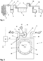
- FIG. 1 shows a simplified schematic diagram of a spinning preparation system.
- the sequence of machines in a spinning preparation system as described below and as illustrated in Figure 1 is given as an example and can also be implemented in other arrangements or with the other machines added.
- the fibers supplied in the form of fiber bales 1 to a spinning mill are broken up into fiber flocks using a bale opener 2.
- the fiber flocks removed from the fiber bales 1 using the bale opener 2 are transported as a fiber flock stream by means of transport fan 3 to a cleaner 5 with the help of transport air or conveyor air in a transport line 4.
- the fiber flock stream passes through the cleaner 5, wherein the fiber flocks are freed of contaminants.
- the fiber flocks are supplied from the cleaner 5 to a mixer 8 via a transport line 6 and with the help of an additional transport fan 7.
- the fiber flocks that have been introduced are mixed in the mixer 8 to obtain the most homogenous possible distribution of the various fiber components.
- the fiber flocks are taken from the mixer 8 and sent with the help of another transport fan 10 to a distributor 11 through a transport line 9.
- the fiber flocks then go from the distributor 11 to the carding machines 12, where the fiber flocks are broken up into individual fibers and the fibers are arranged in parallel, cleaned and supplied in the form of slivers for further processing.
- FIG. 2 shows a schematic diagram of one embodiment of the device.
- the fiber flock stream 24 is sent through transport line 4 to an inlet connection 17 of the cleaner 5.
- the cleaner 5 comprises a cleaner roller 13 which rotates in the direction 15 and is fitted with beater elements 14 on its circumference.
- the fiber flocks guided into the inlet connection 17 are passed, first, around the cleaner roller 13 by the entrained conveyor air and, second, by the rotating cleaner roller 13 and/or the beater elements 14. In doing so, the fiber flocks are conveyed over a grating 16, which removes the contaminants from the fiber flocks.
- the fiber flock stream 24 entering the cleaner 5 through the inlet connection 17 is passed several times around the cleaner roller 13 by means of baffles mounted in a spiral pattern accordingly above the cleaner roller 13 and then conveyed to an outlet 18.
- the space through which the fiber flocks are guided in a spiral pattern can be referred to as the cleaning chamber 30.
- the cleaned fiber flocks leave the cleaner 5 as a fiber flock stream 25, passing through the outlet 18 into an additional
- a static pressure measurement 23 is mounted in the inlet connection 17.
- the static pressure is sent as an actual value 27 to a controller 26, based on the pressure measurement 23.
- an exhaust air pipe 19 is connected to the transport line 4, with the air being guided by an exhaust air fan 20.
- the fan 20 is provided with a drive 21 for regulating the rotational speed of the exhaust air fan 20.
- the exhaust air pipe 19 carries the air withdrawn from the transport line 4 through the exhaust air fan 20 to an exhaust air 22 system (not shown) of a spinning preparation system.
- a control signal 29 in controller 26 is output to the drive 21 of the exhaust air fan 20 based on the difference between the actual value 27 of the pressure and the predetermined target value 28 for the pressure.
- the setpoint for the target value 28 can be received by the controller 26 via a measurement system upstream from the cleaner 5, or the target value may be input into the controller 26 by manual entry.
Landscapes
- Engineering & Computer Science (AREA)
- Textile Engineering (AREA)
- Spinning Or Twisting Of Yarns (AREA)
- Preliminary Treatment Of Fibers (AREA)
Abstract
Description
- The invention relates to a method and a device for regulating a fiber flock stream in a cleaner in a spinning preparation system.
- Fiber processing machines such as intermediate storage devices, mixers and carding machines are used in spinning preparation systems, which serve to clean, mix and separate the fiber material into individual fibers and also to align the fibers in parallel. These machines have in common the fact that they have a flock feed. The fiber material to be processed is fed to the machines in the form of fiber flocks through a pneumatic conveyor. Cleaners used in a spinning preparation system are operated here in continuous operation. In doing so, the fiber flocks are sent to an inlet of the cleaner in a uniform fiber flock stream and transported through the cleaner with the help of a rotating cleaner roller. The fiber flock stream, consisting of the fiber flocks to be cleaned, is guided to the cleaner by the necessary conveyor air with pneumatic conveyance around the fiber flocks. Conveyor air is transported together with fiber flocks through the cleaner. After leaving the cleaner through an outlet, the fiber flock stream is transported by means of a fan to the next machine downstream in the spinning preparation system, for example, a mixer.
- It is known from the prior art that regulators and controllers may be provided to ensure the most uniform possible volume flow of conveyor air and therefore the fiber flock stream. For example,
CH 696 909 A5 - One disadvantage of the known prior art is that the result to be achieved by cleaning the fiber flocks in the cleaner is determined not only by the volume flow of conveyor air and the rotational speed of the cleaner roller but also by the behavior of the fiber flocks inside the cleaner. For example, at a high volume flow, the fiber flocks are driven through the cleaner by the conveyor air, and the desired interaction with the cleaner roller fails to occur. The fiber flocks are compressed and therefore the cleaning effect is inferior due to an elevated pressure in the inlet of the cleaner.
- The object of the invention is thus to create a device for regulating the fiber flock stream in the cleaner, which will permit uniform cleaning of the fiber flocks in the cleaner, regardless of the pneumatic feed and pneumatic discharge of the fiber flocks.
- This object is achieved by the features in the characterizing part of the independent claims.
- To achieve this object, a novel device and a respective method for regulating a fiber flock stream in a cleaner in a spinning preparation system are proposed. The fiber flock stream is guided through a transport line to an inlet into the cleaner and through an outlet out of the cleaner, after passing through a cleaning chamber, such that the cleaner has an inlet connection for connecting the transport line. A static pressure measurement is provided in the fiber flock stream and in the transport line upstream from the inlet connection and the pressure measurement, and an exhaust air pipe connected to the transport line having a vent fan with a drive is provided in the inlet connection or in the transport line upstream from the inlet connection and the pressure measurement. A target value for the pressure is assigned to a predetermined operating state or a current operating state of the cleaner. Control of the drive for the exhaust air van is provided for regulating the target value for the pressure in the cleaner.
- Because of its heterogeneous composition, the influence of the fiber flock stream on operating conditions, in particular the pressure conditions in the cleaner, can be minimized by using this device.
- The static pressure in the fiber flock stream is measured and regulated with the help of the exhaust air fan. In doing so, a static pressure measurement may be carried out in the inlet connection of the cleaner or in the transport line upstream from the inlet connection. Since the static pressure is measured and the flow-dependent dynamic pressure is disregarded, the pressure measurement may take place at a readily accessible location, independently of the flow conditions prevailing at that location inside the transport line or the inlet connection. Alternatively, the pressure measurement may also be provided in the cleaning chamber of the cleaner. The cleaning chamber refers to the area of the cleaner, through which the fiber flock stream is guided between the inlet and the outlet. The measured static pressure is conveyed as an actual value of the pressure to a controller. The actual value is compared by the controller with the predetermined target value, and a control signal is output to the drive of the exhaust air fan according to the defined difference. The exhaust air fan supports the separation of fiber flocks and transport air in the inlet region of the cleaner, which contributes toward maintaining a relationship that is ideal for the desired operation between the transport air and the quantity of fiber flocks contained in the transport air in the cleaner. The connection of the exhaust air pipe to the transport line is provided upstream from the inlet connection into the cleaner and upstream from the pressure measurement, as seen in the direction of flow of the fiber flock stream. The tie-in of the exhaust air pipe to the transport line is equipped with a corresponding system for retaining the fiber flocks in the transport line. Gratings, screens, filter cloths or other devices known from the prior art may be used there.
- A drop in pressure caused by an additional control of the volume stream of conveyor air in the transport system thus has no influence on a pressure zero point or the volume flow in the cleaner. A pressure zero point is established between two fans. This pressure zero point migrates // travels as a function of the operating points of the fans between these fans and the transport path when there is no regulation of the pressure. In the cleaner the same conditions always prevail due to the pressure regulation and any shift in the pressure zero point into the cleaner is suppressed. Influences of a filter house which is usually tied into the exhaust air and transport system can also be compensated. Therefore the inefficient open transfers which are mounted behind each machine in the prior art are omitted in a cleaner. A controlled pressure difference between the inlet and outlet of the cleaner is ensured.
- The static pressure measurement is advantageously arranged in the inlet connection of the cleaner, which therefore yields stable conditions. Suitable pressure measurements are known from the prior art such as spring pressure pickups, piezoresistive or piezoelectric pressure sensors or both capacitive and inductive pressure sensors. Due to the arrangement of the pressure pickup in the inlet connection of the cleaner, the influences from transport of the fiber flocks in the transport line or in the cleaner are minimized.
- It is also advantageous if the prevailing operating state can be determined by the controller from the fiber flock stream. This function can be taken over from measurement results in the upstream components of the spinning preparation system, such as the bale opener or the transport line, for example. It is also conceivable for a measurement to be performed on the conveyor air steam or the quantities of fiber flocks in the transport air stream. Based on these parameters, the cleaner is adjusted (rotational speed, grating alignment, etc.) and the desired cleaning of the fiber flocks is achieved at a certain pressure. However, the reverse path is also conceivable, so that the cleaner is adjusted manually to a certain production and the operating state results from this and is used to determine the target value for the pressure.
- It is also advantageous if the operating state that is predetermined and therefore the target value for the pressure can be set manually on the controller. Therefore, empirical values can be input or an operation can be carried out at an altered pressure without changing other parameters.
- It is particularly advantageous if the regulation is adjusted so that the static pressure in the cleaner is constant. In doing so, fluctuations in the set target value are not taken into account in comparison with regulation based on varying operating parameters, and stable operation is made possible. As an alternative, minor fluctuations in the pressure regulation can be prevented through appropriate damping of the control or selective consideration of changes in target value.
- The exhaust air fan is preferably connected to an exhaust air system of the spinning preparation system. Spinning mills are usually equipped with a central exhaust air system, which filters the exhaust air before discharging it to the outside or feeding it back into the system.
- A method for regulating a fiber flock stream in a cleaner in a spinning preparation system is also proposed, wherein the fiber flock stream is conveyed through a transport line to an inlet into the cleaner, and after passing through a cleaning chamber, is discharged from the cleaner through an outlet, wherein the cleaner has an inlet connection for connection of the transport line. A static pressure is measured in the fiber flock stream in the inlet connection or in the transport line upstream from the inlet connection or in the cleaning chamber. An exhaust air pipe connected to the transport line with an exhaust air fan having a drive is provided in the transport line upstream from the inlet connection and upstream from the pressure measurement. A target value for the pressure in the cleaner is determined, predetermined or prevailing operating state of the cleaner. By controlling the drive of the exhaust air fan, the pressure in the cleaner is regulated at the target value determined previously. The fiber flock stream is advantageously conveyed at a constant conveyor airflow rate through the inlet to the cleaner. Maintaining a constant conveyor air flow rate necessitates a measurement of the conveyor air stream and regulation of the fan in the transport line to the cleaner.
- The invention is explained in greater detail below on the basis of an exemplary embodiment and is illustrated by figures, in which:
- Figure 1
- shows a simplified schematic diagram of a spinning preparation system according to the state of the art, and
- Figure 2
- shows a schematic diagram of one embodiment of the device.
-
Figure 1 shows a simplified schematic diagram of a spinning preparation system. The sequence of machines in a spinning preparation system as described below and as illustrated inFigure 1 is given as an example and can also be implemented in other arrangements or with the other machines added. The fibers supplied in the form offiber bales 1 to a spinning mill are broken up into fiber flocks using abale opener 2. The fiber flocks removed from thefiber bales 1 using thebale opener 2 are transported as a fiber flock stream by means oftransport fan 3 to acleaner 5 with the help of transport air or conveyor air in atransport line 4. The fiber flock stream passes through thecleaner 5, wherein the fiber flocks are freed of contaminants. The fiber flocks are supplied from thecleaner 5 to amixer 8 via atransport line 6 and with the help of anadditional transport fan 7. The fiber flocks that have been introduced are mixed in themixer 8 to obtain the most homogenous possible distribution of the various fiber components. The fiber flocks are taken from themixer 8 and sent with the help of anothertransport fan 10 to adistributor 11 through atransport line 9. The fiber flocks then go from thedistributor 11 to thecarding machines 12, where the fiber flocks are broken up into individual fibers and the fibers are arranged in parallel, cleaned and supplied in the form of slivers for further processing. -
Figure 2 shows a schematic diagram of one embodiment of the device. Thefiber flock stream 24 is sent throughtransport line 4 to aninlet connection 17 of thecleaner 5. Thecleaner 5 comprises acleaner roller 13 which rotates in thedirection 15 and is fitted withbeater elements 14 on its circumference. The fiber flocks guided into theinlet connection 17 are passed, first, around thecleaner roller 13 by the entrained conveyor air and, second, by the rotatingcleaner roller 13 and/or thebeater elements 14. In doing so, the fiber flocks are conveyed over a grating 16, which removes the contaminants from the fiber flocks. Thefiber flock stream 24 entering thecleaner 5 through theinlet connection 17 is passed several times around thecleaner roller 13 by means of baffles mounted in a spiral pattern accordingly above thecleaner roller 13 and then conveyed to anoutlet 18. The space through which the fiber flocks are guided in a spiral pattern can be referred to as the cleaningchamber 30. After passing through the cleaningchamber 30, the cleaned fiber flocks leave thecleaner 5 as afiber flock stream 25, passing through theoutlet 18 into anadditional transport line 6. - A
static pressure measurement 23 is mounted in theinlet connection 17. The static pressure is sent as anactual value 27 to acontroller 26, based on thepressure measurement 23. Upstream from theinlet connection 17, anexhaust air pipe 19 is connected to thetransport line 4, with the air being guided by anexhaust air fan 20. Thefan 20 is provided with adrive 21 for regulating the rotational speed of theexhaust air fan 20. Theexhaust air pipe 19 carries the air withdrawn from thetransport line 4 through theexhaust air fan 20 to anexhaust air 22 system (not shown) of a spinning preparation system. - A
control signal 29 incontroller 26 is output to thedrive 21 of theexhaust air fan 20 based on the difference between theactual value 27 of the pressure and thepredetermined target value 28 for the pressure. The setpoint for thetarget value 28 can be received by thecontroller 26 via a measurement system upstream from thecleaner 5, or the target value may be input into thecontroller 26 by manual entry. -
- 1
- Fiber bales
- 2
- Bale opener
- 3, 7, 10
- Transport fan
- 4, 6, 9
- Transport line
- 5
- Cleaner
- 8
- Mixer
- 11
- Distributor
- 12
- Carding machine
- 13
- Cleaner roller
- 14
- Beater elements
- 15
- Direction of rotation
- 16
- Grating
- 17
- Cleaner inlet
- 18
- Cleaner outlet
- 19
- Exhaust air pipe
- 20
- Exhaust air fan
- 21
- Drive
- 22
- Exhaust air
- 23
- Pressure measurement
- 24
- Fiber flock stream
- 25
- Fiber flock stream
- 26
- Controller
- 27
- Actual value of pressure
- 28
- Target value of pressure
- 29
- Control signal
- 30
- Cleaning chamber
Claims (8)
- A device for regulating a fiber flock stream (24, 25) in a cleaner (5) in a spinning preparation system, wherein the fiber flock stream (24, 25) is guided in a transport line (4) to an inlet into the cleaner (5) after passing through a cleaning chamber (30) via an outlet (18) from the cleaner (5), wherein the cleaner has an inlet connection (17) for connecting the transport line (4), characterized in that a static pressure measurement (23) is provided in the fiber flock stream (24) in the inlet connection (17) or in the transport line (4) upstream from the inlet connection (17) or in the cleaning chamber (30), and an exhaust air pipe (19) connected to the transport line (4) and having an exhaust air fan (20) with a drive (21) is provided upstream from the pressure measurement (23), wherein a target value for the pressure is assigned to a predetermined or prevailing operating state of the cleaner (5), and a controller of the drive (21) of the exhaust air fan (20) is provided for regulating the target pressure value in the cleaner (5).
- The device according to claim 1, characterized in that the static pressure measurement (23) is arranged in the inlet connection (17) of the cleaner (5).
- The device according to claim 1 or 2, characterized in that the prevailing operating state can be ascertained by the controller from the fiber flock stream (24).
- The device according to at least one of the preceding claims, characterized in that the predetermined operating state can be set manually on the controller.
- The device according to at least one of the preceding claims, characterized in that the static pressure in the cleaner (5) is constant.
- The device according to at least one of the preceding claims, characterized in that the exhaust air fan (20) is connected to an exhaust air system of the spinning preparation system.
- A method for regulating a fiber flock stream (24, 25) in a cleaner (5) in a spinning preparation system, wherein the fiber flock stream (24, 25) is conveyed to an inlet into the cleaner (5) via a transport line (4) and is removed from the cleaner (5) via an outlet (18), wherein the cleaner (5) has an inlet connection (17) for connecting the transport line (4), characterized in that a static pressure is measured in the fiber flock stream (24) in the inlet connection (17) or in the transport line (4) upstream from the inlet connection (17) or in the cleaning chamber (30), and an exhaust air pipe (19), which is connected to the transport line (4) and has an exhaust air fan (20) with a drive (21), is provided in the transport line (4) upstream from the inlet connection (17) and upstream from the pressure measurement (23), and a target value for the pressure in the cleaner (5) is determined from a predetermined or prevailing operating state of the cleaner (5), and the pressure in the cleaner (5) is regulated at the target value by control of the drive (21) of the exhaust air fan (20).
- The method according to claim 7, characterized in that the fiber flock stream (24) is conveyed at a constant conveyor air flow rate into the cleaner (5) via the inlet connection (17).
Applications Claiming Priority (1)
| Application Number | Priority Date | Filing Date | Title |
|---|---|---|---|
| CH01073/17A CH714101A1 (en) | 2017-08-30 | 2017-08-30 | Device for controlling a fiber fluff stream in a cleaner. |
Publications (2)
| Publication Number | Publication Date |
|---|---|
| EP3450597A1 true EP3450597A1 (en) | 2019-03-06 |
| EP3450597B1 EP3450597B1 (en) | 2021-10-06 |
Family
ID=63350371
Family Applications (1)
| Application Number | Title | Priority Date | Filing Date |
|---|---|---|---|
| EP18189872.7A Active EP3450597B1 (en) | 2017-08-30 | 2018-08-21 | Device for regulating a fibre flock stream in a cleaner |
Country Status (3)
| Country | Link |
|---|---|
| EP (1) | EP3450597B1 (en) |
| CN (1) | CN109423714B (en) |
| CH (1) | CH714101A1 (en) |
Cited By (1)
| Publication number | Priority date | Publication date | Assignee | Title |
|---|---|---|---|---|
| CZ308782B6 (en) * | 2020-05-22 | 2021-05-12 | Rieter Cz S.R.O. | Method of regulating the flow or pressure in a waste transport device when preparing fibre and equipment |
Citations (4)
| Publication number | Priority date | Publication date | Assignee | Title |
|---|---|---|---|---|
| US4701981A (en) * | 1983-11-24 | 1987-10-27 | Trutzschler Gmbh & Co. Kg | Apparatus for pneumatically feeding a plurality of carding machines |
| US5143485A (en) * | 1989-06-16 | 1992-09-01 | Maschinenfabrik Rieter Ag | Transport air control |
| US5224243A (en) * | 1990-08-20 | 1993-07-06 | Maschinenfabrik Rieter Ag | Cleaning line with false air infeed valve for regulating air flow therein |
| CH696909A5 (en) * | 2003-02-07 | 2008-01-31 | Truetzschler Gmbh & Co Kg | Device for pneumatic Food least a spinning preparation machine, for example, carding or cleaners. |
Family Cites Families (8)
| Publication number | Priority date | Publication date | Assignee | Title |
|---|---|---|---|---|
| DE3617526A1 (en) * | 1986-05-24 | 1987-11-26 | Truetzschler & Co | METHOD AND DEVICE FOR SUPPLYING A NUMBER OF CARDS, CRAWLS OR THE LIKE |
| DE3940524A1 (en) * | 1989-12-07 | 1991-06-13 | Rieter Ag Maschf | Carrier air control |
| DE9017760U1 (en) * | 1990-09-17 | 1991-12-05 | Trützschler GmbH & Co KG, 4050 Mönchengladbach | Device for separating foreign bodies, especially heavy parts such as metal, wood, cardboard parts, stones, etc., from cotton fibre flakes in spinning preparation |
| EP0548023A1 (en) * | 1991-12-17 | 1993-06-23 | Maschinenfabrik Rieter Ag | Flow control of a blow room line |
| DE19906148A1 (en) * | 1999-02-13 | 2000-08-17 | Truetzschler Gmbh & Co Kg | Device for filling a flake store, in particular a card, card, cleaner or the like, with fiber flakes |
| EP1807562B1 (en) * | 2004-11-04 | 2008-10-15 | Maschinenfabrik Rieter Ag | Cleansing device for fibre flocks |
| CH704918A2 (en) * | 2011-05-13 | 2012-11-15 | Rieter Ag Maschf | Device for separating transport air from transport air flow in spinning mill arrangement, has diverting channel for removing air flow, and head piece provided with lockable diverting opening for separating transport air from air flow |
| DE102015106415A1 (en) * | 2014-12-13 | 2016-06-16 | Trützschler GmbH + Co KG Textilmaschinenfabrik | Method and device for feeding a system with fibers |
-
2017
- 2017-08-30 CH CH01073/17A patent/CH714101A1/en not_active Application Discontinuation
-
2018
- 2018-08-21 EP EP18189872.7A patent/EP3450597B1/en active Active
- 2018-08-22 CN CN201810961587.0A patent/CN109423714B/en active Active
Patent Citations (4)
| Publication number | Priority date | Publication date | Assignee | Title |
|---|---|---|---|---|
| US4701981A (en) * | 1983-11-24 | 1987-10-27 | Trutzschler Gmbh & Co. Kg | Apparatus for pneumatically feeding a plurality of carding machines |
| US5143485A (en) * | 1989-06-16 | 1992-09-01 | Maschinenfabrik Rieter Ag | Transport air control |
| US5224243A (en) * | 1990-08-20 | 1993-07-06 | Maschinenfabrik Rieter Ag | Cleaning line with false air infeed valve for regulating air flow therein |
| CH696909A5 (en) * | 2003-02-07 | 2008-01-31 | Truetzschler Gmbh & Co Kg | Device for pneumatic Food least a spinning preparation machine, for example, carding or cleaners. |
Cited By (2)
| Publication number | Priority date | Publication date | Assignee | Title |
|---|---|---|---|---|
| CZ308782B6 (en) * | 2020-05-22 | 2021-05-12 | Rieter Cz S.R.O. | Method of regulating the flow or pressure in a waste transport device when preparing fibre and equipment |
| EP3913119A1 (en) * | 2020-05-22 | 2021-11-24 | Maschinenfabrik Rieter AG | Dispatch transport system in fibre preparation |
Also Published As
| Publication number | Publication date |
|---|---|
| CN109423714A (en) | 2019-03-05 |
| CH714101A1 (en) | 2019-03-15 |
| EP3450597B1 (en) | 2021-10-06 |
| CN109423714B (en) | 2022-06-24 |
Similar Documents
| Publication | Publication Date | Title |
|---|---|---|
| CN104379822B (en) | Method and device for adjusting fiber feed to carding machine | |
| CN110318124B (en) | Feeding device for carding machines | |
| JPH0213048B2 (en) | ||
| US6681450B2 (en) | Apparatus for regulating fiber tuft quantities supplied to a carding machine | |
| CN107002309B (en) | Method and apparatus for supplying fiber to equipment | |
| CN102209475A (en) | Device and method for feeding cut tobacco from a tobacco delivery unit to a tobacco processing machine | |
| US4527306A (en) | Spinning preparation system and method for air-conditioning the same | |
| US5121522A (en) | Humidity and temperature air conditioning in a textile processing line | |
| US4345356A (en) | Mechanism for eliminating impurities from fibrous material, in particular cotton | |
| US4864693A (en) | Flow-through fiber preparation feed system and method | |
| CN109023599B (en) | Production control in the blowroom | |
| CN1032822A (en) | Adjustment of processing section of fiber processing equipment | |
| US4701981A (en) | Apparatus for pneumatically feeding a plurality of carding machines | |
| EP3450597B1 (en) | Device for regulating a fibre flock stream in a cleaner | |
| CN110195273B (en) | Feeding equipment for cards | |
| EP3633086B1 (en) | Flock conveyance in a fiber preparation system | |
| US5143485A (en) | Transport air control | |
| US10793977B2 (en) | Pressure regulation in a flock feed | |
| JPH04245927A (en) | Transport duct mechanism of spinning factory | |
| CN1448556A (en) | Apparatus for separating transporting air in fibrous material transportation | |
| US4928353A (en) | Method and means for effecting a controllable change in the production of a fiber-processing machine | |
| US6907644B2 (en) | Apparatus for pneumatically feeding at least one spinning preparation machine, for example a carding machine or cleaner | |
| JPH04245928A (en) | Device for separating from cotton fiber mass in spinning preparatory device foreign matter particularly heavy material such as metal piece, wood piece, corrugated cardboard piece and stone | |
| GB930930A (en) | Improvements in or relating to automatic carding plants of textile spinning mills | |
| CN102125302A (en) | Production of filter cables and filter cable machine |
Legal Events
| Date | Code | Title | Description |
|---|---|---|---|
| PUAI | Public reference made under article 153(3) epc to a published international application that has entered the european phase |
Free format text: ORIGINAL CODE: 0009012 |
|
| STAA | Information on the status of an ep patent application or granted ep patent |
Free format text: STATUS: THE APPLICATION HAS BEEN PUBLISHED |
|
| AK | Designated contracting states |
Kind code of ref document: A1 Designated state(s): AL AT BE BG CH CY CZ DE DK EE ES FI FR GB GR HR HU IE IS IT LI LT LU LV MC MK MT NL NO PL PT RO RS SE SI SK SM TR |
|
| AX | Request for extension of the european patent |
Extension state: BA ME |
|
| STAA | Information on the status of an ep patent application or granted ep patent |
Free format text: STATUS: REQUEST FOR EXAMINATION WAS MADE |
|
| 17P | Request for examination filed |
Effective date: 20190830 |
|
| RBV | Designated contracting states (corrected) |
Designated state(s): AL AT BE BG CH CY CZ DE DK EE ES FI FR GB GR HR HU IE IS IT LI LT LU LV MC MK MT NL NO PL PT RO RS SE SI SK SM TR |
|
| GRAP | Despatch of communication of intention to grant a patent |
Free format text: ORIGINAL CODE: EPIDOSNIGR1 |
|
| STAA | Information on the status of an ep patent application or granted ep patent |
Free format text: STATUS: GRANT OF PATENT IS INTENDED |
|
| INTG | Intention to grant announced |
Effective date: 20210514 |
|
| GRAS | Grant fee paid |
Free format text: ORIGINAL CODE: EPIDOSNIGR3 |
|
| GRAA | (expected) grant |
Free format text: ORIGINAL CODE: 0009210 |
|
| STAA | Information on the status of an ep patent application or granted ep patent |
Free format text: STATUS: THE PATENT HAS BEEN GRANTED |
|
| AK | Designated contracting states |
Kind code of ref document: B1 Designated state(s): AL AT BE BG CH CY CZ DE DK EE ES FI FR GB GR HR HU IE IS IT LI LT LU LV MC MK MT NL NO PL PT RO RS SE SI SK SM TR |
|
| REG | Reference to a national code |
Ref country code: GB Ref legal event code: FG4D |
|
| REG | Reference to a national code |
Ref country code: CH Ref legal event code: EP Ref country code: AT Ref legal event code: REF Ref document number: 1436309 Country of ref document: AT Kind code of ref document: T Effective date: 20211015 |
|
| REG | Reference to a national code |
Ref country code: IE Ref legal event code: FG4D |
|
| REG | Reference to a national code |
Ref country code: DE Ref legal event code: R096 Ref document number: 602018024534 Country of ref document: DE |
|
| REG | Reference to a national code |
Ref country code: LT Ref legal event code: MG9D |
|
| REG | Reference to a national code |
Ref country code: NL Ref legal event code: MP Effective date: 20211006 |
|
| REG | Reference to a national code |
Ref country code: AT Ref legal event code: MK05 Ref document number: 1436309 Country of ref document: AT Kind code of ref document: T Effective date: 20211006 |
|
| PG25 | Lapsed in a contracting state [announced via postgrant information from national office to epo] |
Ref country code: RS Free format text: LAPSE BECAUSE OF FAILURE TO SUBMIT A TRANSLATION OF THE DESCRIPTION OR TO PAY THE FEE WITHIN THE PRESCRIBED TIME-LIMIT Effective date: 20211006 Ref country code: LT Free format text: LAPSE BECAUSE OF FAILURE TO SUBMIT A TRANSLATION OF THE DESCRIPTION OR TO PAY THE FEE WITHIN THE PRESCRIBED TIME-LIMIT Effective date: 20211006 Ref country code: FI Free format text: LAPSE BECAUSE OF FAILURE TO SUBMIT A TRANSLATION OF THE DESCRIPTION OR TO PAY THE FEE WITHIN THE PRESCRIBED TIME-LIMIT Effective date: 20211006 Ref country code: BG Free format text: LAPSE BECAUSE OF FAILURE TO SUBMIT A TRANSLATION OF THE DESCRIPTION OR TO PAY THE FEE WITHIN THE PRESCRIBED TIME-LIMIT Effective date: 20220106 Ref country code: AT Free format text: LAPSE BECAUSE OF FAILURE TO SUBMIT A TRANSLATION OF THE DESCRIPTION OR TO PAY THE FEE WITHIN THE PRESCRIBED TIME-LIMIT Effective date: 20211006 |
|
| PG25 | Lapsed in a contracting state [announced via postgrant information from national office to epo] |
Ref country code: IS Free format text: LAPSE BECAUSE OF FAILURE TO SUBMIT A TRANSLATION OF THE DESCRIPTION OR TO PAY THE FEE WITHIN THE PRESCRIBED TIME-LIMIT Effective date: 20220206 Ref country code: SE Free format text: LAPSE BECAUSE OF FAILURE TO SUBMIT A TRANSLATION OF THE DESCRIPTION OR TO PAY THE FEE WITHIN THE PRESCRIBED TIME-LIMIT Effective date: 20211006 Ref country code: PT Free format text: LAPSE BECAUSE OF FAILURE TO SUBMIT A TRANSLATION OF THE DESCRIPTION OR TO PAY THE FEE WITHIN THE PRESCRIBED TIME-LIMIT Effective date: 20220207 Ref country code: PL Free format text: LAPSE BECAUSE OF FAILURE TO SUBMIT A TRANSLATION OF THE DESCRIPTION OR TO PAY THE FEE WITHIN THE PRESCRIBED TIME-LIMIT Effective date: 20211006 Ref country code: NO Free format text: LAPSE BECAUSE OF FAILURE TO SUBMIT A TRANSLATION OF THE DESCRIPTION OR TO PAY THE FEE WITHIN THE PRESCRIBED TIME-LIMIT Effective date: 20220106 Ref country code: NL Free format text: LAPSE BECAUSE OF FAILURE TO SUBMIT A TRANSLATION OF THE DESCRIPTION OR TO PAY THE FEE WITHIN THE PRESCRIBED TIME-LIMIT Effective date: 20211006 Ref country code: LV Free format text: LAPSE BECAUSE OF FAILURE TO SUBMIT A TRANSLATION OF THE DESCRIPTION OR TO PAY THE FEE WITHIN THE PRESCRIBED TIME-LIMIT Effective date: 20211006 Ref country code: HR Free format text: LAPSE BECAUSE OF FAILURE TO SUBMIT A TRANSLATION OF THE DESCRIPTION OR TO PAY THE FEE WITHIN THE PRESCRIBED TIME-LIMIT Effective date: 20211006 Ref country code: GR Free format text: LAPSE BECAUSE OF FAILURE TO SUBMIT A TRANSLATION OF THE DESCRIPTION OR TO PAY THE FEE WITHIN THE PRESCRIBED TIME-LIMIT Effective date: 20220107 Ref country code: ES Free format text: LAPSE BECAUSE OF FAILURE TO SUBMIT A TRANSLATION OF THE DESCRIPTION OR TO PAY THE FEE WITHIN THE PRESCRIBED TIME-LIMIT Effective date: 20211006 |
|
| REG | Reference to a national code |
Ref country code: DE Ref legal event code: R097 Ref document number: 602018024534 Country of ref document: DE |
|
| PG25 | Lapsed in a contracting state [announced via postgrant information from national office to epo] |
Ref country code: SM Free format text: LAPSE BECAUSE OF FAILURE TO SUBMIT A TRANSLATION OF THE DESCRIPTION OR TO PAY THE FEE WITHIN THE PRESCRIBED TIME-LIMIT Effective date: 20211006 Ref country code: SK Free format text: LAPSE BECAUSE OF FAILURE TO SUBMIT A TRANSLATION OF THE DESCRIPTION OR TO PAY THE FEE WITHIN THE PRESCRIBED TIME-LIMIT Effective date: 20211006 Ref country code: RO Free format text: LAPSE BECAUSE OF FAILURE TO SUBMIT A TRANSLATION OF THE DESCRIPTION OR TO PAY THE FEE WITHIN THE PRESCRIBED TIME-LIMIT Effective date: 20211006 Ref country code: EE Free format text: LAPSE BECAUSE OF FAILURE TO SUBMIT A TRANSLATION OF THE DESCRIPTION OR TO PAY THE FEE WITHIN THE PRESCRIBED TIME-LIMIT Effective date: 20211006 Ref country code: DK Free format text: LAPSE BECAUSE OF FAILURE TO SUBMIT A TRANSLATION OF THE DESCRIPTION OR TO PAY THE FEE WITHIN THE PRESCRIBED TIME-LIMIT Effective date: 20211006 Ref country code: CZ Free format text: LAPSE BECAUSE OF FAILURE TO SUBMIT A TRANSLATION OF THE DESCRIPTION OR TO PAY THE FEE WITHIN THE PRESCRIBED TIME-LIMIT Effective date: 20211006 |
|
| PLBE | No opposition filed within time limit |
Free format text: ORIGINAL CODE: 0009261 |
|
| STAA | Information on the status of an ep patent application or granted ep patent |
Free format text: STATUS: NO OPPOSITION FILED WITHIN TIME LIMIT |
|
| 26N | No opposition filed |
Effective date: 20220707 |
|
| PG25 | Lapsed in a contracting state [announced via postgrant information from national office to epo] |
Ref country code: AL Free format text: LAPSE BECAUSE OF FAILURE TO SUBMIT A TRANSLATION OF THE DESCRIPTION OR TO PAY THE FEE WITHIN THE PRESCRIBED TIME-LIMIT Effective date: 20211006 |
|
| PG25 | Lapsed in a contracting state [announced via postgrant information from national office to epo] |
Ref country code: SI Free format text: LAPSE BECAUSE OF FAILURE TO SUBMIT A TRANSLATION OF THE DESCRIPTION OR TO PAY THE FEE WITHIN THE PRESCRIBED TIME-LIMIT Effective date: 20211006 |
|
| PG25 | Lapsed in a contracting state [announced via postgrant information from national office to epo] |
Ref country code: MC Free format text: LAPSE BECAUSE OF FAILURE TO SUBMIT A TRANSLATION OF THE DESCRIPTION OR TO PAY THE FEE WITHIN THE PRESCRIBED TIME-LIMIT Effective date: 20211006 |
|
| REG | Reference to a national code |
Ref country code: CH Ref legal event code: PL |
|
| GBPC | Gb: european patent ceased through non-payment of renewal fee |
Effective date: 20220821 |
|
| PG25 | Lapsed in a contracting state [announced via postgrant information from national office to epo] |
Ref country code: LU Free format text: LAPSE BECAUSE OF NON-PAYMENT OF DUE FEES Effective date: 20220821 Ref country code: LI Free format text: LAPSE BECAUSE OF NON-PAYMENT OF DUE FEES Effective date: 20220831 Ref country code: CH Free format text: LAPSE BECAUSE OF NON-PAYMENT OF DUE FEES Effective date: 20220831 |
|
| REG | Reference to a national code |
Ref country code: BE Ref legal event code: MM Effective date: 20220831 |
|
| PG25 | Lapsed in a contracting state [announced via postgrant information from national office to epo] |
Ref country code: IT Free format text: LAPSE BECAUSE OF FAILURE TO SUBMIT A TRANSLATION OF THE DESCRIPTION OR TO PAY THE FEE WITHIN THE PRESCRIBED TIME-LIMIT Effective date: 20211006 |
|
| P01 | Opt-out of the competence of the unified patent court (upc) registered |
Effective date: 20230519 |
|
| PG25 | Lapsed in a contracting state [announced via postgrant information from national office to epo] |
Ref country code: IE Free format text: LAPSE BECAUSE OF NON-PAYMENT OF DUE FEES Effective date: 20220821 Ref country code: FR Free format text: LAPSE BECAUSE OF NON-PAYMENT OF DUE FEES Effective date: 20220831 |
|
| PG25 | Lapsed in a contracting state [announced via postgrant information from national office to epo] |
Ref country code: BE Free format text: LAPSE BECAUSE OF NON-PAYMENT OF DUE FEES Effective date: 20220831 |
|
| PG25 | Lapsed in a contracting state [announced via postgrant information from national office to epo] |
Ref country code: GB Free format text: LAPSE BECAUSE OF NON-PAYMENT OF DUE FEES Effective date: 20220821 |
|
| PG25 | Lapsed in a contracting state [announced via postgrant information from national office to epo] |
Ref country code: HU Free format text: LAPSE BECAUSE OF FAILURE TO SUBMIT A TRANSLATION OF THE DESCRIPTION OR TO PAY THE FEE WITHIN THE PRESCRIBED TIME-LIMIT; INVALID AB INITIO Effective date: 20180821 |
|
| PG25 | Lapsed in a contracting state [announced via postgrant information from national office to epo] |
Ref country code: CY Free format text: LAPSE BECAUSE OF FAILURE TO SUBMIT A TRANSLATION OF THE DESCRIPTION OR TO PAY THE FEE WITHIN THE PRESCRIBED TIME-LIMIT Effective date: 20211006 |
|
| PG25 | Lapsed in a contracting state [announced via postgrant information from national office to epo] |
Ref country code: MK Free format text: LAPSE BECAUSE OF FAILURE TO SUBMIT A TRANSLATION OF THE DESCRIPTION OR TO PAY THE FEE WITHIN THE PRESCRIBED TIME-LIMIT Effective date: 20211006 |
|
| PG25 | Lapsed in a contracting state [announced via postgrant information from national office to epo] |
Ref country code: MT Free format text: LAPSE BECAUSE OF FAILURE TO SUBMIT A TRANSLATION OF THE DESCRIPTION OR TO PAY THE FEE WITHIN THE PRESCRIBED TIME-LIMIT Effective date: 20211006 |
|
| PGFP | Annual fee paid to national office [announced via postgrant information from national office to epo] |
Ref country code: DE Payment date: 20250819 Year of fee payment: 8 |
|
| PGFP | Annual fee paid to national office [announced via postgrant information from national office to epo] |
Ref country code: TR Payment date: 20250813 Year of fee payment: 8 |