EP3450270B1 - Landwirtschaftliches kraftfahrzeug - Google Patents
Landwirtschaftliches kraftfahrzeug Download PDFInfo
- Publication number
- EP3450270B1 EP3450270B1 EP18174604.1A EP18174604A EP3450270B1 EP 3450270 B1 EP3450270 B1 EP 3450270B1 EP 18174604 A EP18174604 A EP 18174604A EP 3450270 B1 EP3450270 B1 EP 3450270B1
- Authority
- EP
- European Patent Office
- Prior art keywords
- trailer
- agricultural vehicle
- vehicle combination
- brake
- agricultural
- Prior art date
- Legal status (The legal status is an assumption and is not a legal conclusion. Google has not performed a legal analysis and makes no representation as to the accuracy of the status listed.)
- Active
Links
Images


Classifications
-
- B—PERFORMING OPERATIONS; TRANSPORTING
- B60—VEHICLES IN GENERAL
- B60T—VEHICLE BRAKE CONTROL SYSTEMS OR PARTS THEREOF; BRAKE CONTROL SYSTEMS OR PARTS THEREOF, IN GENERAL; ARRANGEMENT OF BRAKING ELEMENTS ON VEHICLES IN GENERAL; PORTABLE DEVICES FOR PREVENTING UNWANTED MOVEMENT OF VEHICLES; VEHICLE MODIFICATIONS TO FACILITATE COOLING OF BRAKES
- B60T7/00—Brake-action initiating means
- B60T7/02—Brake-action initiating means for personal initiation
- B60T7/04—Brake-action initiating means for personal initiation foot actuated
-
- B—PERFORMING OPERATIONS; TRANSPORTING
- B60—VEHICLES IN GENERAL
- B60T—VEHICLE BRAKE CONTROL SYSTEMS OR PARTS THEREOF; BRAKE CONTROL SYSTEMS OR PARTS THEREOF, IN GENERAL; ARRANGEMENT OF BRAKING ELEMENTS ON VEHICLES IN GENERAL; PORTABLE DEVICES FOR PREVENTING UNWANTED MOVEMENT OF VEHICLES; VEHICLE MODIFICATIONS TO FACILITATE COOLING OF BRAKES
- B60T13/00—Transmitting braking action from initiating means to ultimate brake actuator with power assistance or drive; Brake systems incorporating such transmitting means, e.g. air-pressure brake systems
- B60T13/10—Transmitting braking action from initiating means to ultimate brake actuator with power assistance or drive; Brake systems incorporating such transmitting means, e.g. air-pressure brake systems with fluid assistance, drive, or release
- B60T13/66—Electrical control in fluid-pressure brake systems
-
- B—PERFORMING OPERATIONS; TRANSPORTING
- B60—VEHICLES IN GENERAL
- B60T—VEHICLE BRAKE CONTROL SYSTEMS OR PARTS THEREOF; BRAKE CONTROL SYSTEMS OR PARTS THEREOF, IN GENERAL; ARRANGEMENT OF BRAKING ELEMENTS ON VEHICLES IN GENERAL; PORTABLE DEVICES FOR PREVENTING UNWANTED MOVEMENT OF VEHICLES; VEHICLE MODIFICATIONS TO FACILITATE COOLING OF BRAKES
- B60T13/00—Transmitting braking action from initiating means to ultimate brake actuator with power assistance or drive; Brake systems incorporating such transmitting means, e.g. air-pressure brake systems
- B60T13/10—Transmitting braking action from initiating means to ultimate brake actuator with power assistance or drive; Brake systems incorporating such transmitting means, e.g. air-pressure brake systems with fluid assistance, drive, or release
- B60T13/66—Electrical control in fluid-pressure brake systems
- B60T13/662—Electrical control in fluid-pressure brake systems characterised by specified functions of the control system components
-
- B—PERFORMING OPERATIONS; TRANSPORTING
- B60—VEHICLES IN GENERAL
- B60T—VEHICLE BRAKE CONTROL SYSTEMS OR PARTS THEREOF; BRAKE CONTROL SYSTEMS OR PARTS THEREOF, IN GENERAL; ARRANGEMENT OF BRAKING ELEMENTS ON VEHICLES IN GENERAL; PORTABLE DEVICES FOR PREVENTING UNWANTED MOVEMENT OF VEHICLES; VEHICLE MODIFICATIONS TO FACILITATE COOLING OF BRAKES
- B60T13/00—Transmitting braking action from initiating means to ultimate brake actuator with power assistance or drive; Brake systems incorporating such transmitting means, e.g. air-pressure brake systems
- B60T13/74—Transmitting braking action from initiating means to ultimate brake actuator with power assistance or drive; Brake systems incorporating such transmitting means, e.g. air-pressure brake systems with electrical assistance or drive
-
- B—PERFORMING OPERATIONS; TRANSPORTING
- B60—VEHICLES IN GENERAL
- B60T—VEHICLE BRAKE CONTROL SYSTEMS OR PARTS THEREOF; BRAKE CONTROL SYSTEMS OR PARTS THEREOF, IN GENERAL; ARRANGEMENT OF BRAKING ELEMENTS ON VEHICLES IN GENERAL; PORTABLE DEVICES FOR PREVENTING UNWANTED MOVEMENT OF VEHICLES; VEHICLE MODIFICATIONS TO FACILITATE COOLING OF BRAKES
- B60T15/00—Construction arrangement, or operation of valves incorporated in power brake systems and not covered by groups B60T11/00 or B60T13/00
- B60T15/02—Application and release valves
- B60T15/18—Triple or other relay valves which allow step-wise application or release and which are actuated by brake-pipe pressure variation to connect brake cylinders or equivalent to compressed air or vacuum source or atmosphere
- B60T15/181—Trailer control valves
-
- B—PERFORMING OPERATIONS; TRANSPORTING
- B60—VEHICLES IN GENERAL
- B60T—VEHICLE BRAKE CONTROL SYSTEMS OR PARTS THEREOF; BRAKE CONTROL SYSTEMS OR PARTS THEREOF, IN GENERAL; ARRANGEMENT OF BRAKING ELEMENTS ON VEHICLES IN GENERAL; PORTABLE DEVICES FOR PREVENTING UNWANTED MOVEMENT OF VEHICLES; VEHICLE MODIFICATIONS TO FACILITATE COOLING OF BRAKES
- B60T15/00—Construction arrangement, or operation of valves incorporated in power brake systems and not covered by groups B60T11/00 or B60T13/00
- B60T15/02—Application and release valves
- B60T15/18—Triple or other relay valves which allow step-wise application or release and which are actuated by brake-pipe pressure variation to connect brake cylinders or equivalent to compressed air or vacuum source or atmosphere
- B60T15/182—Trailer brake valves
-
- B—PERFORMING OPERATIONS; TRANSPORTING
- B60—VEHICLES IN GENERAL
- B60T—VEHICLE BRAKE CONTROL SYSTEMS OR PARTS THEREOF; BRAKE CONTROL SYSTEMS OR PARTS THEREOF, IN GENERAL; ARRANGEMENT OF BRAKING ELEMENTS ON VEHICLES IN GENERAL; PORTABLE DEVICES FOR PREVENTING UNWANTED MOVEMENT OF VEHICLES; VEHICLE MODIFICATIONS TO FACILITATE COOLING OF BRAKES
- B60T15/00—Construction arrangement, or operation of valves incorporated in power brake systems and not covered by groups B60T11/00 or B60T13/00
- B60T15/02—Application and release valves
- B60T15/18—Triple or other relay valves which allow step-wise application or release and which are actuated by brake-pipe pressure variation to connect brake cylinders or equivalent to compressed air or vacuum source or atmosphere
- B60T15/20—Triple or other relay valves which allow step-wise application or release and which are actuated by brake-pipe pressure variation to connect brake cylinders or equivalent to compressed air or vacuum source or atmosphere controlled by two fluid pressures
-
- B—PERFORMING OPERATIONS; TRANSPORTING
- B60—VEHICLES IN GENERAL
- B60T—VEHICLE BRAKE CONTROL SYSTEMS OR PARTS THEREOF; BRAKE CONTROL SYSTEMS OR PARTS THEREOF, IN GENERAL; ARRANGEMENT OF BRAKING ELEMENTS ON VEHICLES IN GENERAL; PORTABLE DEVICES FOR PREVENTING UNWANTED MOVEMENT OF VEHICLES; VEHICLE MODIFICATIONS TO FACILITATE COOLING OF BRAKES
- B60T15/00—Construction arrangement, or operation of valves incorporated in power brake systems and not covered by groups B60T11/00 or B60T13/00
- B60T15/02—Application and release valves
- B60T15/18—Triple or other relay valves which allow step-wise application or release and which are actuated by brake-pipe pressure variation to connect brake cylinders or equivalent to compressed air or vacuum source or atmosphere
- B60T15/20—Triple or other relay valves which allow step-wise application or release and which are actuated by brake-pipe pressure variation to connect brake cylinders or equivalent to compressed air or vacuum source or atmosphere controlled by two fluid pressures
- B60T15/203—Trailer control valves
-
- B—PERFORMING OPERATIONS; TRANSPORTING
- B60—VEHICLES IN GENERAL
- B60T—VEHICLE BRAKE CONTROL SYSTEMS OR PARTS THEREOF; BRAKE CONTROL SYSTEMS OR PARTS THEREOF, IN GENERAL; ARRANGEMENT OF BRAKING ELEMENTS ON VEHICLES IN GENERAL; PORTABLE DEVICES FOR PREVENTING UNWANTED MOVEMENT OF VEHICLES; VEHICLE MODIFICATIONS TO FACILITATE COOLING OF BRAKES
- B60T15/00—Construction arrangement, or operation of valves incorporated in power brake systems and not covered by groups B60T11/00 or B60T13/00
- B60T15/02—Application and release valves
- B60T15/18—Triple or other relay valves which allow step-wise application or release and which are actuated by brake-pipe pressure variation to connect brake cylinders or equivalent to compressed air or vacuum source or atmosphere
- B60T15/20—Triple or other relay valves which allow step-wise application or release and which are actuated by brake-pipe pressure variation to connect brake cylinders or equivalent to compressed air or vacuum source or atmosphere controlled by two fluid pressures
- B60T15/206—Trailer brake valves
-
- B—PERFORMING OPERATIONS; TRANSPORTING
- B60—VEHICLES IN GENERAL
- B60T—VEHICLE BRAKE CONTROL SYSTEMS OR PARTS THEREOF; BRAKE CONTROL SYSTEMS OR PARTS THEREOF, IN GENERAL; ARRANGEMENT OF BRAKING ELEMENTS ON VEHICLES IN GENERAL; PORTABLE DEVICES FOR PREVENTING UNWANTED MOVEMENT OF VEHICLES; VEHICLE MODIFICATIONS TO FACILITATE COOLING OF BRAKES
- B60T15/00—Construction arrangement, or operation of valves incorporated in power brake systems and not covered by groups B60T11/00 or B60T13/00
- B60T15/02—Application and release valves
- B60T15/18—Triple or other relay valves which allow step-wise application or release and which are actuated by brake-pipe pressure variation to connect brake cylinders or equivalent to compressed air or vacuum source or atmosphere
- B60T15/20—Triple or other relay valves which allow step-wise application or release and which are actuated by brake-pipe pressure variation to connect brake cylinders or equivalent to compressed air or vacuum source or atmosphere controlled by two fluid pressures
- B60T15/22—Triple or other relay valves which allow step-wise application or release and which are actuated by brake-pipe pressure variation to connect brake cylinders or equivalent to compressed air or vacuum source or atmosphere controlled by two fluid pressures with one or more auxiliary valves, for braking, releasing, filling reservoirs
- B60T15/223—Trailer control valves
-
- B—PERFORMING OPERATIONS; TRANSPORTING
- B60—VEHICLES IN GENERAL
- B60T—VEHICLE BRAKE CONTROL SYSTEMS OR PARTS THEREOF; BRAKE CONTROL SYSTEMS OR PARTS THEREOF, IN GENERAL; ARRANGEMENT OF BRAKING ELEMENTS ON VEHICLES IN GENERAL; PORTABLE DEVICES FOR PREVENTING UNWANTED MOVEMENT OF VEHICLES; VEHICLE MODIFICATIONS TO FACILITATE COOLING OF BRAKES
- B60T15/00—Construction arrangement, or operation of valves incorporated in power brake systems and not covered by groups B60T11/00 or B60T13/00
- B60T15/02—Application and release valves
- B60T15/18—Triple or other relay valves which allow step-wise application or release and which are actuated by brake-pipe pressure variation to connect brake cylinders or equivalent to compressed air or vacuum source or atmosphere
- B60T15/20—Triple or other relay valves which allow step-wise application or release and which are actuated by brake-pipe pressure variation to connect brake cylinders or equivalent to compressed air or vacuum source or atmosphere controlled by two fluid pressures
- B60T15/22—Triple or other relay valves which allow step-wise application or release and which are actuated by brake-pipe pressure variation to connect brake cylinders or equivalent to compressed air or vacuum source or atmosphere controlled by two fluid pressures with one or more auxiliary valves, for braking, releasing, filling reservoirs
- B60T15/226—Trailer brake valves
-
- B—PERFORMING OPERATIONS; TRANSPORTING
- B60—VEHICLES IN GENERAL
- B60T—VEHICLE BRAKE CONTROL SYSTEMS OR PARTS THEREOF; BRAKE CONTROL SYSTEMS OR PARTS THEREOF, IN GENERAL; ARRANGEMENT OF BRAKING ELEMENTS ON VEHICLES IN GENERAL; PORTABLE DEVICES FOR PREVENTING UNWANTED MOVEMENT OF VEHICLES; VEHICLE MODIFICATIONS TO FACILITATE COOLING OF BRAKES
- B60T15/00—Construction arrangement, or operation of valves incorporated in power brake systems and not covered by groups B60T11/00 or B60T13/00
- B60T15/02—Application and release valves
- B60T15/36—Other control devices or valves characterised by definite functions
- B60T15/46—Other control devices or valves characterised by definite functions for retarding braking action to prevent rear vehicles of a vehicle train overtaking the forward ones
-
- B—PERFORMING OPERATIONS; TRANSPORTING
- B60—VEHICLES IN GENERAL
- B60T—VEHICLE BRAKE CONTROL SYSTEMS OR PARTS THEREOF; BRAKE CONTROL SYSTEMS OR PARTS THEREOF, IN GENERAL; ARRANGEMENT OF BRAKING ELEMENTS ON VEHICLES IN GENERAL; PORTABLE DEVICES FOR PREVENTING UNWANTED MOVEMENT OF VEHICLES; VEHICLE MODIFICATIONS TO FACILITATE COOLING OF BRAKES
- B60T17/00—Component parts, details, or accessories of power brake systems not covered by groups B60T8/00, B60T13/00 or B60T15/00, or presenting other characteristic features
- B60T17/18—Safety devices; Monitoring
- B60T17/22—Devices for monitoring or checking brake systems; Signal devices
- B60T17/221—Procedure or apparatus for checking or keeping in a correct functioning condition of brake systems
-
- B—PERFORMING OPERATIONS; TRANSPORTING
- B60—VEHICLES IN GENERAL
- B60T—VEHICLE BRAKE CONTROL SYSTEMS OR PARTS THEREOF; BRAKE CONTROL SYSTEMS OR PARTS THEREOF, IN GENERAL; ARRANGEMENT OF BRAKING ELEMENTS ON VEHICLES IN GENERAL; PORTABLE DEVICES FOR PREVENTING UNWANTED MOVEMENT OF VEHICLES; VEHICLE MODIFICATIONS TO FACILITATE COOLING OF BRAKES
- B60T7/00—Brake-action initiating means
- B60T7/02—Brake-action initiating means for personal initiation
- B60T7/04—Brake-action initiating means for personal initiation foot actuated
- B60T7/042—Brake-action initiating means for personal initiation foot actuated by electrical means, e.g. using travel or force sensors
-
- B—PERFORMING OPERATIONS; TRANSPORTING
- B60—VEHICLES IN GENERAL
- B60T—VEHICLE BRAKE CONTROL SYSTEMS OR PARTS THEREOF; BRAKE CONTROL SYSTEMS OR PARTS THEREOF, IN GENERAL; ARRANGEMENT OF BRAKING ELEMENTS ON VEHICLES IN GENERAL; PORTABLE DEVICES FOR PREVENTING UNWANTED MOVEMENT OF VEHICLES; VEHICLE MODIFICATIONS TO FACILITATE COOLING OF BRAKES
- B60T7/00—Brake-action initiating means
- B60T7/02—Brake-action initiating means for personal initiation
- B60T7/08—Brake-action initiating means for personal initiation hand actuated
- B60T7/085—Brake-action initiating means for personal initiation hand actuated by electrical means, e.g. travel, force sensors
-
- B—PERFORMING OPERATIONS; TRANSPORTING
- B60—VEHICLES IN GENERAL
- B60T—VEHICLE BRAKE CONTROL SYSTEMS OR PARTS THEREOF; BRAKE CONTROL SYSTEMS OR PARTS THEREOF, IN GENERAL; ARRANGEMENT OF BRAKING ELEMENTS ON VEHICLES IN GENERAL; PORTABLE DEVICES FOR PREVENTING UNWANTED MOVEMENT OF VEHICLES; VEHICLE MODIFICATIONS TO FACILITATE COOLING OF BRAKES
- B60T7/00—Brake-action initiating means
- B60T7/12—Brake-action initiating means for automatic initiation; for initiation not subject to will of driver or passenger
- B60T7/20—Brake-action initiating means for automatic initiation; for initiation not subject to will of driver or passenger specially for trailers, e.g. in case of uncoupling of or overrunning by trailer
-
- B—PERFORMING OPERATIONS; TRANSPORTING
- B60—VEHICLES IN GENERAL
- B60T—VEHICLE BRAKE CONTROL SYSTEMS OR PARTS THEREOF; BRAKE CONTROL SYSTEMS OR PARTS THEREOF, IN GENERAL; ARRANGEMENT OF BRAKING ELEMENTS ON VEHICLES IN GENERAL; PORTABLE DEVICES FOR PREVENTING UNWANTED MOVEMENT OF VEHICLES; VEHICLE MODIFICATIONS TO FACILITATE COOLING OF BRAKES
- B60T8/00—Arrangements for adjusting wheel-braking force to meet varying vehicular or ground-surface conditions, e.g. limiting or varying distribution of braking force
- B60T8/17—Using electrical or electronic regulation means to control braking
- B60T8/1701—Braking or traction control means specially adapted for particular types of vehicles
- B60T8/1708—Braking or traction control means specially adapted for particular types of vehicles for lorries or tractor-trailer combinations
-
- B—PERFORMING OPERATIONS; TRANSPORTING
- B60—VEHICLES IN GENERAL
- B60T—VEHICLE BRAKE CONTROL SYSTEMS OR PARTS THEREOF; BRAKE CONTROL SYSTEMS OR PARTS THEREOF, IN GENERAL; ARRANGEMENT OF BRAKING ELEMENTS ON VEHICLES IN GENERAL; PORTABLE DEVICES FOR PREVENTING UNWANTED MOVEMENT OF VEHICLES; VEHICLE MODIFICATIONS TO FACILITATE COOLING OF BRAKES
- B60T8/00—Arrangements for adjusting wheel-braking force to meet varying vehicular or ground-surface conditions, e.g. limiting or varying distribution of braking force
- B60T8/17—Using electrical or electronic regulation means to control braking
- B60T8/172—Determining control parameters used in the regulation, e.g. by calculations involving measured or detected parameters
-
- B—PERFORMING OPERATIONS; TRANSPORTING
- B60—VEHICLES IN GENERAL
- B60T—VEHICLE BRAKE CONTROL SYSTEMS OR PARTS THEREOF; BRAKE CONTROL SYSTEMS OR PARTS THEREOF, IN GENERAL; ARRANGEMENT OF BRAKING ELEMENTS ON VEHICLES IN GENERAL; PORTABLE DEVICES FOR PREVENTING UNWANTED MOVEMENT OF VEHICLES; VEHICLE MODIFICATIONS TO FACILITATE COOLING OF BRAKES
- B60T8/00—Arrangements for adjusting wheel-braking force to meet varying vehicular or ground-surface conditions, e.g. limiting or varying distribution of braking force
- B60T8/17—Using electrical or electronic regulation means to control braking
- B60T8/1755—Brake regulation specially adapted to control the stability of the vehicle, e.g. taking into account yaw rate or transverse acceleration in a curve
- B60T8/17551—Brake regulation specially adapted to control the stability of the vehicle, e.g. taking into account yaw rate or transverse acceleration in a curve determining control parameters related to vehicle stability used in the regulation, e.g. by calculations involving measured or detected parameters
-
- B—PERFORMING OPERATIONS; TRANSPORTING
- B60—VEHICLES IN GENERAL
- B60T—VEHICLE BRAKE CONTROL SYSTEMS OR PARTS THEREOF; BRAKE CONTROL SYSTEMS OR PARTS THEREOF, IN GENERAL; ARRANGEMENT OF BRAKING ELEMENTS ON VEHICLES IN GENERAL; PORTABLE DEVICES FOR PREVENTING UNWANTED MOVEMENT OF VEHICLES; VEHICLE MODIFICATIONS TO FACILITATE COOLING OF BRAKES
- B60T8/00—Arrangements for adjusting wheel-braking force to meet varying vehicular or ground-surface conditions, e.g. limiting or varying distribution of braking force
- B60T8/18—Arrangements for adjusting wheel-braking force to meet varying vehicular or ground-surface conditions, e.g. limiting or varying distribution of braking force responsive to vehicle weight or load, e.g. load distribution
- B60T8/1887—Arrangements for adjusting wheel-braking force to meet varying vehicular or ground-surface conditions, e.g. limiting or varying distribution of braking force responsive to vehicle weight or load, e.g. load distribution especially adapted for tractor-trailer combinations
-
- B—PERFORMING OPERATIONS; TRANSPORTING
- B60—VEHICLES IN GENERAL
- B60T—VEHICLE BRAKE CONTROL SYSTEMS OR PARTS THEREOF; BRAKE CONTROL SYSTEMS OR PARTS THEREOF, IN GENERAL; ARRANGEMENT OF BRAKING ELEMENTS ON VEHICLES IN GENERAL; PORTABLE DEVICES FOR PREVENTING UNWANTED MOVEMENT OF VEHICLES; VEHICLE MODIFICATIONS TO FACILITATE COOLING OF BRAKES
- B60T8/00—Arrangements for adjusting wheel-braking force to meet varying vehicular or ground-surface conditions, e.g. limiting or varying distribution of braking force
- B60T8/24—Arrangements for adjusting wheel-braking force to meet varying vehicular or ground-surface conditions, e.g. limiting or varying distribution of braking force responsive to vehicle inclination or change of direction, e.g. negotiating bends
- B60T8/248—Trailer sway, e.g. for preventing jackknifing
-
- B—PERFORMING OPERATIONS; TRANSPORTING
- B60—VEHICLES IN GENERAL
- B60T—VEHICLE BRAKE CONTROL SYSTEMS OR PARTS THEREOF; BRAKE CONTROL SYSTEMS OR PARTS THEREOF, IN GENERAL; ARRANGEMENT OF BRAKING ELEMENTS ON VEHICLES IN GENERAL; PORTABLE DEVICES FOR PREVENTING UNWANTED MOVEMENT OF VEHICLES; VEHICLE MODIFICATIONS TO FACILITATE COOLING OF BRAKES
- B60T8/00—Arrangements for adjusting wheel-braking force to meet varying vehicular or ground-surface conditions, e.g. limiting or varying distribution of braking force
- B60T8/32—Arrangements for adjusting wheel-braking force to meet varying vehicular or ground-surface conditions, e.g. limiting or varying distribution of braking force responsive to a speed condition, e.g. acceleration or deceleration
- B60T8/321—Arrangements for adjusting wheel-braking force to meet varying vehicular or ground-surface conditions, e.g. limiting or varying distribution of braking force responsive to a speed condition, e.g. acceleration or deceleration deceleration
- B60T8/323—Systems specially adapted for tractor-trailer combinations
-
- B—PERFORMING OPERATIONS; TRANSPORTING
- B60—VEHICLES IN GENERAL
- B60T—VEHICLE BRAKE CONTROL SYSTEMS OR PARTS THEREOF; BRAKE CONTROL SYSTEMS OR PARTS THEREOF, IN GENERAL; ARRANGEMENT OF BRAKING ELEMENTS ON VEHICLES IN GENERAL; PORTABLE DEVICES FOR PREVENTING UNWANTED MOVEMENT OF VEHICLES; VEHICLE MODIFICATIONS TO FACILITATE COOLING OF BRAKES
- B60T8/00—Arrangements for adjusting wheel-braking force to meet varying vehicular or ground-surface conditions, e.g. limiting or varying distribution of braking force
- B60T8/32—Arrangements for adjusting wheel-braking force to meet varying vehicular or ground-surface conditions, e.g. limiting or varying distribution of braking force responsive to a speed condition, e.g. acceleration or deceleration
- B60T8/321—Arrangements for adjusting wheel-braking force to meet varying vehicular or ground-surface conditions, e.g. limiting or varying distribution of braking force responsive to a speed condition, e.g. acceleration or deceleration deceleration
- B60T8/3255—Systems in which the braking action is dependent on brake pedal data
-
- B—PERFORMING OPERATIONS; TRANSPORTING
- B60—VEHICLES IN GENERAL
- B60T—VEHICLE BRAKE CONTROL SYSTEMS OR PARTS THEREOF; BRAKE CONTROL SYSTEMS OR PARTS THEREOF, IN GENERAL; ARRANGEMENT OF BRAKING ELEMENTS ON VEHICLES IN GENERAL; PORTABLE DEVICES FOR PREVENTING UNWANTED MOVEMENT OF VEHICLES; VEHICLE MODIFICATIONS TO FACILITATE COOLING OF BRAKES
- B60T2230/00—Monitoring, detecting special vehicle behaviour; Counteracting thereof
- B60T2230/06—Tractor-trailer swaying
-
- B—PERFORMING OPERATIONS; TRANSPORTING
- B60—VEHICLES IN GENERAL
- B60T—VEHICLE BRAKE CONTROL SYSTEMS OR PARTS THEREOF; BRAKE CONTROL SYSTEMS OR PARTS THEREOF, IN GENERAL; ARRANGEMENT OF BRAKING ELEMENTS ON VEHICLES IN GENERAL; PORTABLE DEVICES FOR PREVENTING UNWANTED MOVEMENT OF VEHICLES; VEHICLE MODIFICATIONS TO FACILITATE COOLING OF BRAKES
- B60T2260/00—Interaction of vehicle brake system with other systems
- B60T2260/04—Automatic transmission
Definitions
- the invention relates to an agricultural train according to the preamble of claim 1.
- Agricultural machines such as tractors are often used in addition to pure field work for transport tasks in which, for example, harvested crops are transported on trailers.
- One or more trailers are usually pulled by a towing vehicle and together with the towing vehicle form a so-called agricultural train.
- trailers often have a so-called overrun brake, which acts mechanically on one or more axles. In the case of the overrun brake, when the trailer runs into the towing vehicle, i.e.
- Jackknifing is also a problem on trains with pneumatic or hydraulic braking systems.
- the braking systems of the trailers can be adapted to the braking systems of the respective towing vehicle. This is done for the trailer-side Brake system on a brake valve, hereinafter referred to as trailer brake valve, a permanent control deviation (offset) is set, which means that when the agricultural train brakes, the trailer brake system responds before the towing vehicle's brake system responds.
- Control deviation or offset in this sense means that the trailer brake valve responds sooner than the brake valve (s) of the towing vehicle, so that the trailer brake system is actuated earlier than the towing vehicle brake system and / or that the trailer brake valve opens faster than the brake valve (s) of the towing vehicle, so that the brake pressure of the trailer brake system is initially higher than the brake pressure of the towing vehicle brake system.
- the invention is based on the problem of providing an agricultural train with a towing vehicle and at least one trailer, which in a simple manner ensures that the braking system functions reliably.
- An agricultural train comprises a towing vehicle, in particular a tractor, and at least one trailer which can be or is coupled to it.
- a trailer is understood to mean any vehicle pulled by an access vehicle without its own drive and with at least one axle, which, in addition to trailers for transporting a load, also includes agricultural work units that have at least one non-driven axle.
- the respective trailer has a trailer brake system for braking the respective trailer axle or axles.
- the towing vehicle which is driven in contrast to the trailer, has a separate towing vehicle brake system.
- the brake systems are controlled and / or regulated via a control device, which is in particular part of the towing vehicle, but can also be part of the respective trailer.
- the operating and / or status parameters are in particular those that specify the agricultural train and in particular the combination of towing vehicle and trailer or trailers, with special features such as the wear condition of the trailer brakes, the trailer weight, the response pressure and / or the response time of the brakes , the type of brake system or the like. Be taken into account.
- the control device automatically adapts the braking behavior of the towing vehicle and trailer or trailers optimally to the current conditions, so that the trailer or the trailer runs into the towing vehicle at the beginning of a Braking can be prevented. Since the control device automatically makes the necessary settings, when a trailer is changed or one or more trailers are coupled to the towing vehicle, no, or at least no noteworthy, adjustments or conversion measures are required required by an operator. There is also no longer any need for an operator to carefully familiarize himself with documentation for appropriate adjustments. The proposed agricultural train is therefore not only more user-friendly, but also increases road safety, since the risk of inadequate adaptation of the braking systems of the towing vehicle and trailer is minimized.
- At least one of the brake systems has a trailer brake valve, in particular electronically controllable, for actuating at least one brake of the respective trailer.
- the trailer brake valve is arranged in particular on the towing vehicle.
- the automatic setting of the at least one brake system, in particular the trailer brake system, by the control device includes the setting of a control deviation or an offset of the trailer brake valve.
- Setting a control deviation or an offset means that the trailer brake valve reacts differently in terms of time than the brake valve (s) of the towing vehicle, in particular in such a way that the trailer's brake system responds initially or this initially responds more strongly than the towing vehicle's brake system, which ultimately prevents the trailer from running into the towing vehicle and, in the worst case, so-called jackknifing.
- the setting of the control deviation causes, in particular, a higher brake pressure in the trailer brake system and / or an earlier actuation of this brake system.
- the braking behavior is adapted according to the embodiment according to the invention so that the trailer-side brakes respond sooner and more strongly than the towing vehicle-side brakes, whereby the trailer can be prevented from running into the towing vehicle at the beginning of a braking process.
- the braking behavior is adjusted accordingly so that the brakes of all trailers respond sooner and more strongly than the brakes on the towing vehicle, whereby all trailers can be prevented from running into the towing vehicle at the beginning of a braking process.
- control device can suggest or predefine the driver a suggestion for an optimal sequence of the trailers such that the brakes of the rear of two trailers respond sooner and / or more strongly than the brakes of the front of the two trailers.
- order of the trailers is suggested in this way or specified that the more and / or earlier braking trailer is arranged at the rear or at the end of the train.
- Claim 3 defines options for triggering or starting the automatic setting, in particular calibration, of the respective brake system by the control device.
- the automatic setting can take place after the respective trailer has been coupled to the respective towing vehicle and recognized or automatically identified by the control device, the automatic setting particularly preferably starting fully automatically, ie. H. without intervention by the operator.
- the operator makes at least one operator input that starts the automatic setting process and / or on which the automatic setting is based, the operator input including, for example, the input or selection of the trailer type.
- the operating and / or status parameters are determined during the operation of the agricultural train, in particular while driving, for example during acceleration and / or deceleration (claim 6) and transmitted to the control device.
- the control device retrieves the operating and / or status parameters from a database.
- the data can be stored in the database on a trailer-specific basis, i. H. for certain trailers and / or specific to the towing vehicle, d. H. for certain towing vehicles, be deposited (claim 5).
- Claims 7 and 8 relate to various preferred operating parameters. Preferred state parameters are listed in claim 9.
- Claim 10 defines the possibility that the control device can store determined operating and / or status parameters and / or a set or to be set control deviation of the respective trailer brake valve and / or can retrieve and / or update correspondingly stored data.
- the data can also be linked to further data in the database or in the memory of the control device, which claim 11 specifies in more detail.
- claims 12 to 16 relate to a set-up assistant for the agricultural train, which carries out the adjustment of the respective brake system or at least supports such an adjustment of the brake system.
- the control device Due to the preferably closed brake circuit, in particular the hydraulic or pneumatic brake circuit, the control device finally also allows the brake pressure of the trailer brake system (s) and / or the towing vehicle brake system to be monitored, with deviations from a predetermined target value or target value range being displayed (claim 17).
- FIG. 1 As an example of an agricultural train 1, a towing vehicle 2 in the form of a tractor with a single trailer 3 arranged thereon is shown in FIG Form of a baler shown in a schematic side view. In principle, however, the proposed train 1 can also have more than one trailer 3.
- a towing vehicle 2 in the proposed sense can be any agricultural machine such as a forage harvester, a combine harvester or a tractor with or without an attached working unit.
- attached, in particular saddled, attachments are to be understood as trailers 3 in the proposed sense.
- the towing vehicle 2 and trailer 3 are each equipped with their own brake system 4, 5, the braking system 4 of the trailer 3 being defined as a trailer braking system and the braking system 5 of the towing vehicle 2 being defined as the towing vehicle braking system.
- the agricultural train 1 has a control device 6 for controlling and / or regulating at least one of the brake systems 4, 5, which is configured to automatically control the respective brake system 4, 5 as a function of at least one operating parameter and / or at least one state parameter of the agricultural train 1 adjust.
- the control device 6 here and preferably has a processor 7 and a memory 8 with a database in which operating and / or status parameters or their values and / or standard values for operating and / or State parameters can be saved.
- the braking behavior of the agricultural train 1 can be optimally adapted to the existing combination of a specific towing vehicle 2 with a specific trailer 3, so that, in particular at the beginning of a braking process of the agricultural Train 1, the trailer 3 running onto the towing vehicle 2 is avoided.
- one of the brake systems 4, 5, here the trailer brake system 4 of the trailer 3 has an electronically controllable one for this purpose
- Trailer brake valve 9 for actuating at least one brake 10 of the trailer 3.
- the aforementioned automatic setting of the at least one brake system 4, 5, here and preferably both brake systems 4, 5, includes in particular the setting of a control deviation of the trailer brake valve 9, which is here and preferably part of the towing vehicle 2, such that the brakes 10 of the trailer 3 at the beginning of a braking process earlier and / or more strongly than the brakes 11 of the towing vehicle 2 are actuated.
- the setting of the at least one brake system 4, 5 is carried out here and preferably automatically by the control device 6 when the trailer 3 is or has been coupled to the towing vehicle 2.
- the trailer 3 is connected to the towing vehicle 2 via an interface 13, which not only connects the trailer brake system 4 with the towing vehicle brake system 5 to form a common brake circuit, represented here symbolically by the brake lines 14, but also also the trailer brake valve 9 via a control line 15 to the control device 6.
- connection via the interface 13 activates a signal generator or transmitter, which is provided here and preferably on the trailer 3, namely a so-called "beacon", whereupon a trailer 3 specifying Bluetooth code is transmitted to an assigned receiver (not shown), the control device 6 reading out correspondingly stored setting values from a database based on the received data and based on this the trailer braking system 4 and / or the towing vehicle braking system 5 optimally to the specific combination of towing vehicle 2 and trailer 3 adapts.
- the tag 3 can also be equipped with a barcode and / or RFID transponder, with which data specifying the tag 3 can also be generated and processed by the control device 6.
- Optical detection of the trailer 3 and / or towing vehicle 2 via a camera arrangement is also conceivable in order to specify the specific trailer 3 to be coupled or coupled and to transmit corresponding data to the control device 6.
- an operator input can be made, for example, via a terminal 17, in particular a vehicle-mounted terminal 17, or a smart device (wireless, mobile and networked electronic device such as a smartphone, tablet or the like).
- UI user interfaces
- MMI multimedia interfaces
- the operator can use special apps or farm management software to make the operator input.
- the operating and / or state parameters can be determined during operation, in particular driving operation, preferably during acceleration and / or deceleration, of the agricultural train 1 and transmitted to the control device 6.
- operator inputs are also possible.
- the control device 6 retrieves corresponding data from a database or a memory 8, which in particular is part of the control device 6.
- the operating and / or status parameters can be stored in the database on a trailer-specific and / or tractor-specific basis.
- the at least one operating parameter can be selected from the group comprising a load signal (air mass per stroke) of the vehicle drive, a hydraulic transmission pressure, a pneumatic or hydraulic brake pressure (pressure in the brake line), a tensile force and / or compressive force acting between the towing vehicle 2 and trailer 3 , a power take-off shaft and / or engine torque, a power take-off shaft and / or engine speed, an acceleration of the trailer 3 and / or towing vehicle 2 and an external pressure requirement, in particular hydraulic or pneumatic pressure requirement, for example a pressure requirement for the operation of a working unit such as a baling press
- a corresponding operating parameter is determined here and preferably based on sensor data of at least one sensor selected from the group comprising an air mass sensor, a hydraulic pressure sensor, a pneumatic pressure sensor, a tensile force sensor, a compressive force sensor, a rotation torque sensor, a speed sensor and an acceleration sensor.
- the at least one status parameter can in turn be selected from the group comprising the type of coupling between towing vehicle 2 and trailer 3 and / or between two trailers 3 (ball coupling, hook coupling, jaw coupling, etc.), the degree of wear of at least one of the brakes 10, 11 or all brakes 10 , 11 of the trailer 3 and / or the towing vehicle 2, the type and / or the weight of the trailer 3 and / or the towing vehicle 2 in the loaded or unloaded state, the type of the braking system 4, 5 of the trailer 3 and / or the towing vehicle 2 (hydraulic brake system, pneumatic brake system, number of brakes, brake type such as drum brakes or disc brakes etc.), the minimum response pressure of the brakes 10 of the respective trailer 3 and / or towing vehicle 2, the response time of the brakes 10 of the respective trailer 3 and / or towing vehicle 2 , and the braking power of the trailer 3 and / or the towing vehicle 2.
- the control device 6 has here and preferably as described a memory 8 which allows the at least one determined operating and / or status parameter and / or the set or to be set control deviation of the trailer brake valve 9 to be stored.
- a memory 8 which allows the at least one determined operating and / or status parameter and / or the set or to be set control deviation of the trailer brake valve 9 to be stored.
- control device 6 can here and preferably also use standard values for the operating and / or status parameters or retrieve them from the database.
- the standard values for the operating and / or status parameters can then be updated by the control device 6 in the further course, preferably automatically.
- the operating and / or status parameters and / or the control deviations of the trailer brake valve 9 can also be linked to further data.
- the link to a trailer stored in the database, the link to sequence management, the link to a GPS position, the link to an agricultural work order, are merely exemplary and not conclusive.
- the agricultural train 1, for example as a component of the control device 6, can also have a setup assistant 16 that carries out or supports the automatic setting of the at least one brake system 4, 5.
- Support can consist, for example, in the specification of certain setting options for the operator, from which the operator can make a selection and / or which the operator can confirm.
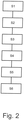
- the setup assistant 16 can according to a first exemplary embodiment ( Fig. 2 ) be configured to store in a first step S1 the transmission output torque that the agricultural train 1 requires while it accelerates up to a predetermined driving speed without actuating a brake 10, 11, in a second step S2 the agricultural train 1 after storing the Stop the transmission output torque, then build up a predetermined brake pressure in a third step S3, then set a transmission output torque in a fourth step S4 that corresponds to the transmission output torque during acceleration to the predetermined speed, plus a predetermined control deviation for the torque at the transmission output, the brake pressure is then reduced again in a fifth step S5, and in a sixth step S6, as soon as the agricultural train 1 starts moving again, the control deviation of the trailer brake valve 9 is determined for a predetermined or desired B. reming behavior is to be set.
- the setup assistant 16 can be configured to initially set a defined driving speed in a first step S1 ', then in a second step S2' when the accelerator pedal is actuated, in particular by a defined or maximum actuation, in particular by the driver, the brake pressure of the trailer brake system 4 until the beginning of braking of the trailer 3 is confirmed by an operator input (step S3a ') or is detected based on the sensor data of the at least one sensor (step S3b'), depending on the brake pressure at the point in time the beginning of the braking of the trailer 3 has been confirmed or detected, the control deviation of the trailer brake valve 9 is set in a fourth step S4 '.
- the setup assistant 16 can also be configured, in the case of an agricultural train 1 with more than one trailer 3, for example with two trailers 3 arranged one behind the other, a sequence of the trailers 3 within the agricultural train as a function of one or more of the state parameters described 1 and / or to check the order of the trailers 3 within the agricultural train 1.
- the setup assistant 16 takes into account the type of coupling, the type and / or weight of the trailer 3 and / or the towing vehicle 2 in the loaded or unloaded state and / or response pressure and / or response time of the brakes 10 of the trailer 3
- Setup wizard 16 also display or output a warning.
- the setup assistant 16 suggests that the first trailer as the front trailer 3 and the second trailer as the rear trailer in the event that the towing vehicle 2 is to be coupled with a first trailer and a second trailer to form an agricultural train 1 must be provided because, for example, the minimum response pressure of the brakes 10 of the first trailer is greater than that of the second trailer and / or the response time of the brakes 10 of the first trailer is longer than that of the second trailer, in other words at the beginning of a braking process of the agricultural train 1 the second trailer decelerates sooner and / or more than the first trailer.
- the setup assistant 16 particularly preferably allows the control deviation of the trailer brake valve 9 to be increased by a predetermined amount based on a standard control deviation as soon as During braking, an overrun mode of the trailer 3 is detected which exceeds a predetermined setpoint or setpoint range.
- the brake lines 14 of the brake system form, to monitor the brake pressure of the trailer brake system 4 and / or the towing vehicle brake system 5 and to detect a deviation from a predetermined target value or target value range, which can also be stored in memory 8 in the database.
- a display can take place, for example, optically and / or acoustically.
Landscapes
- Engineering & Computer Science (AREA)
- Transportation (AREA)
- Mechanical Engineering (AREA)
- Physics & Mathematics (AREA)
- Fluid Mechanics (AREA)
- Regulating Braking Force (AREA)
Description
- Die Erfindung betrifft einen landwirtschaftlichen Zug nach dem Oberbegriff des Anspruchs 1.
- Landwirtschaftliche Arbeitsmaschinen wie Traktoren werden neben der reinen Feldarbeit auch oft für Transportaufgaben eingesetzt, bei denen beispielsweise auf Anhänger verladenes Erntegut transportiert wird. Dabei werden üblicherweise ein oder mehrere Anhänger von einem Zugfahrzeug gezogen und bilden zusammen mit dem Zugfahrzeug einen sog. landwirtschaftlichen Zug. Mit der zunehmenden Größe und Leistungsfähigkeit der landwirtschaftlichen Arbeitsmaschinen steigt auch die Möglichkeit, größere und schwerer beladene Anhänger zu ziehen, wobei die zulässigen Höchstgeschwindigkeiten, die landwirtschaftliche Arbeitsmaschinen im öffentlichen Straßenverkehr fahren dürfen, ebenfalls ansteigen. Anhänger weisen oftmals eine sog. Auflaufbremse auf, welche mechanisch auf eine oder mehrere Achsen wirkt. Bei der Auflaufbremse wird bei einem Auflaufen des Anhängers auf das Zugfahrzeug, also bei einer Verzögerung des Zugfahrzeugs, automatisch die Bremsanlage des auflaufenden Anhängers betätigt, so dass dieser durch die anhängerseitigen Bremsen ebenfalls verzögert wird. Hierbei kann es bauartbedingt jedoch zu kurzen zeitlichen Verzögerungen bis zum Ansprechen der Auflaufbremse kommen, wodurch kritische Fahrsituationen entstehen können. So kann beispielsweise ein stark bremsendes Zugfahrzeug bis zum Ansprechen der Auflaufbremse des Anhängers durch diesen geschoben und bereits in einen instabilen Fahrzustand gebracht werden (z.B. Einknicken des Zuges, sog. "Jackknifing"). Das zuvor Gesagte gilt nicht nur für mit beispielsweise Erntegut beladbare Anhänger, sondern auch gezogene und somit zu bremsende landwirtschaftliche Arbeitsaggregate wie Ballenpressen, Ackerbearbeitungsaggregate o. dgl., die vorliegend ebenfalls Anhänger im vorschlagsgemäßen Sinne bilden.
- Die Problematik des Jackknifing besteht auch bei Zügen mit pneumatischer oder hydraulischer Bremsanlage. Um hierbei kritische Fahrsituationen durch Aufschieben des Anhängers auf das Zugfahrzeug zu verhindern, können Bremsanlagen der Anhänger an die Bremsanlage des jeweiligen Zugfahrzeugs angepasst werden. Hierzu wird für die anhängerseitige Bremsanlage an einem Bremsventil, im Folgenden Anhängerbremsventil genannt, eine bleibende Regelabweichung (Offset) eingestellt, die bewirkt, dass bei einem Abbremsen des landwirtschaftlichen Zuges zunächst die Bremsanlage des Anhängers anspricht, bevor die Bremsanlage des Zugfahrzeugs anspricht. Regelabweichung bzw. Offset bedeutet in diesem Sinne, dass das Anhängerbremsventil eher als das oder die Bremsventile des Zugfahrzeugs anspricht, so dass die Anhängerbremsanlage früher als die Zugfahrzeugbremsanlage betätigt wird, und/oder, dass das Anhängerbremsventil schneller als das oder die Bremsventile des Zugfahrzeugs öffnet, so dass der Bremsdruck der Anhängerbremsanlage zunächst höher als der Bremsdruck der Zugfahrzeugbremsanlage ist.
- Allerdings ist eine optimale Einstellung der Regelabweichung für jeden einzelnen Anhänger bzw. jede einzelne Kombination aus Zugfahrzeug und Anhänger für einen Fahrer des Zuges kaum möglich, da hier zu viele Parameter, beispielsweise der Verschleißzustand der Anhängerbremsen, das Anhängergewicht und/oder die Art der Bremsanlage, berücksichtigt werden müssen. Insbesondere sind hierzu auch eine Reihe von mechanischen Umbaumaßnahmen nötig, die nicht ohne entsprechendes Werkzeug durchgeführt werden können. Solche Anpassungen bzw. Umbaumaßnahmen werden daher oft nicht, zumindest nicht vollständig, durchgeführt, insbesondere bei häufigem Anhängerwechsel.
- Aus dem Stand der Technik sind unterschiedliche Bremseinrichtungen für landwirtschaftliche Züge bekannt. Aus der
DE 10 2014 220 686 A1 ist beispielsweise bekannt, bei einer Bremsbetätigung eine anhängerseitige Achse derart zu bremsen, dass ein Verzögerungs-Sollwert erreicht wird, der einem Verzögerungswert des Zugfahrzeugs ohne Anhänger bei einer entsprechenden Bremsbetätigung entspricht. Aus derWO 20157052293 A1 - Aus der
DE 10 2015 108 681 A1 ist ein Verfahren sowie eine Vorrichtung zur Stabilisierung einer Zugfahrzeug-Anhängerkombination während der Fahrt bekannt. - Der Erfindung liegt das Problem zugrunde, einen landwirtschaftlichen Zug mit einem Zugfahrzeug und mindestens einem Anhänger bereitzustellen, der auf einfache Weise eine sichere Funktion des Bremssystems gewährleistet.
- Das obige Problem wird bei einem landwirtschaftlichen Zug gemäß dem Oberbegriff von Anspruch 1 durch die Merkmale des kennzeichnenden Teils von Anspruch 1 gelöst.
- Ein landwirtschaftlicher Zug umfasst ein Zugfahrzeug, insbesondere einen Traktor, und mindestens einen damit koppelbaren oder gekoppelten Anhänger. Unter einem Anhänger wird jedwedes von einem Zufahrzeug gezogenes Fahrzeug ohne eigenen Antrieb und mit mindestens einer Achse verstanden, worunter neben Anhängern zum Transportieren einer Ladung auch landwirtschaftliche Arbeitsaggregate verstanden werden, die mindestens eine nicht angetriebene Achse aufweisen. Der jeweilige Anhänger verfügt über eine Anhängerbremsanlage zum Bremsen der jeweiligen Anhängerachse oder - achsen. Das Zugfahrzeug, welches im Unterschied zu dem Anhänger angetrieben ist, weist eine separate Zugfahrzeugbremsanlage auf. Die Bremsanlagen werden über eine Steuervorrichtung, die insbesondere Bestandteil des Zugfahrzeugs ist, aber auch Bestandteil des jeweiligen Anhängers sein kann, gesteuert und/oder geregelt.
- Wesentlich bei dem vorschlagsgemäßen landwirtschaftlichen Zug ist nun, dass über die Steuervorrichtung eine Einstellung, insbesondere eine bleibende Einstellung, mindestens einer der Bremsanlagen unter Berücksichtigung von Betriebs- und/oder Zustandsparametern des landwirtschaftlichen Zugs ermöglicht wird. Die Betriebs- und/oder Zustandsparameter sind insbesondere solche, die den landwirtschaftlichen Zug und insbesondere die Kombination aus Zugfahrzeug und Anhänger bzw. Anhängern spezifizieren, wobei vorzugsweise auch Besonderheiten wie der Verschleißzustand der Anhängerbremsen, das Anhängergewicht, der Ansprechdruck und/oder die Ansprechzeit der Bremsen, die Art der Bremsanlage o. dgl. berücksichtigt werden. Auf Basis entsprechender Parameter, die im Weiteren noch näher erläutert werden, passt die Steuervorrichtung damit automatisch das Bremsverhalten von Zugfahrzeug und Anhänger bzw. Anhängern optimal an die aktuellen Gegebenheiten an, so dass ein Auflaufen des Anhängers bzw. der Anhänger auf das Zugfahrzeug zu Beginn eines Bremsvorgangs verhindert werden kann. Da die Steuervorrichtung die notwendigen Einstellungen automatisch vornimmt, sind bei einem Anhängerwechsel bzw. Ankoppeln eines oder mehrerer Anhänger an das Zugfahrzeug keine oder zumindest keine nennenswerten Anpassungen oder Umbaumaßnahmen durch eine Bedienperson erforderlich. Auch besteht nicht mehr die Notwendigkeit, dass eine Bedienperson sich sorgfältig in eine Dokumentation für entsprechende Anpassungen einarbeitet. Der vorschlagsgemäße landwirtschaftliche Zug ist somit nicht nur bedienerfreundlicher, sondern erhöht auch die Verkehrssicherheit, da das Risiko einer unzureichenden Anpassung der Bremsanlagen von Zugfahrzeug und Anhänger minimiert wird.
- Bei der Ausgestaltung gemäß Anspruch 2 weist mindestens eine der Bremsanlagen ein, insbesondere elektronisch, ansteuerbares Anhängerbremsventil zur Betätigung mindestens einer Bremse des jeweiligen Anhängers auf. Das Anhängerbremsventil ist dabei insbesondere am Zugfahrzeug angeordnet. In diesem Fall umfasst die automatische Einstellung der mindestens einen Bremsanlage, insbesondere der Anhängerbremsanlage, durch die Steuervorrichtung die Einstellung einer Regelabweichung bzw. eines Offsets des Anhängerbremsventils. Einstellung einer Regelabweichung bzw. eines Offsets meint, dass das Anhängerbremsventil durch diese Einstellung insbesondere zeitlich anders als das oder die Bremsventile des Zugfahrzeugs reagiert, und zwar derart, dass zunächst die Bremsanlage des Anhängers anspricht bzw. diese zunächst stärker anspricht als die Bremsanlage des Zugfahrzeugs, wodurch letztlich ein Auflaufen des Anhängers auf das Zugfahrzeug und schlimmstenfalls das sog. Jackknifing verhindert wird. Die Einstellung der Regelabweichung bewirkt insbesondere einen höheren Bremsdruck in der Anhängerbremsanlage und/oder eine frühere Betätigung dieser Bremsanlage.
- Das Bremsverhalten wird nach der erfindungsgemäßen Ausgestaltung so angepasst, dass die anhängerseitigen Bremsen eher und stärker als die zugfahrzeugseitigen Bremsen ansprechen, wodurch ein Auflaufen des Anhängers auf das Zugfahrzeug zu Beginn eines Bremsvorgangs verhindert werden kann. Bei einem Zug mit mehr als einem Anhänger, beispielsweise mit zwei Anhängern, wird das Bremsverhalten entsprechend so angepasst, dass die Bremsen aller Anhänger eher und stärker als die zugfahrzeugseitigen Bremsen ansprechen, wodurch zu Beginn eines Bremsvorgangs ein Auflaufen aller Anhänger auf das Zugfahrzeugverhindert werden kann. Zusätzlich kann dem Fahrer von der Steuervorrichtung ein Vorschlag für eine optimale Reihenfolge der Anhänger vorgeschlagen bzw. vorgegeben werden, derart, dass die Bremsen des jeweils hinteren von zwei Anhängern eher und/oder stärker als die Bremsen des jeweils vorderen der zwei Anhänger ansprechen. Insbesondere wird die Reihenfolge der Anhänger derart vorgeschlagen bzw. vorgegeben, dass der stärker und/oder früher bremsende Anhänger hinten bzw. am Zugende angeordnet ist.
- Anspruch 3 definiert Möglichkeiten, die automatische Einstellung, insbesondere Kalibrierung, der jeweiligen Bremsanlage durch die Steuervorrichtung auszulösen bzw. zu starten. Beispielsweise kann die automatische Einstellung in einer bevorzugten Ausgestaltung erfolgen, nachdem der jeweilige Anhänger an das jeweilige Zugfahrzeug angekoppelt und von der Steuervorrichtung erkannt bzw. automatisch identifiziert worden ist, wobei die automatische Einstellung besonders bevorzugt vollautomatisch startet, d. h. ohne Eingriff durch die Bedienperson. Grundsätzlich ist es aber genauso denkbar, dass die Bedienperson mindestens eine Bedienereingabe macht, die den automatischen Einstellvorgang startet und/oder auf der die automatische Einstellung basiert, wobei die Bedienereingabe beispielsweise die Eingabe oder Auswahl des Anhängertyps umfasst.
- Bei der Ausgestaltung gemäß Anspruch 4 werden die Betriebs- und/oder Zustandsparameter während des Betriebs des landwirtschaftlichen Zuges, insbesondere während des Fahrbetriebs, beispielsweise während einer Beschleunigung und/oder Verzögerung (Anspruch 6), ermittelt und an die Steuervorrichtung übertragen. Es ist aber auch denkbar, der Steuervorrichtung durch eine Bedienereingabe die Betriebs- und/oder Zustandsparameter vorzugeben. Ebenso ist es denkbar, dass die Steuervorrichtung die Betriebs- und/oder Zustandsparameter aus einer Datenbank abruft. Die Daten können in der Datenbank anhängerspezifisch, d. h. für bestimmte Anhänger, und/oder zugfahrzeugspezifisch, d. h. für bestimmte Zugfahrzeuge, hinterlegt sein (Anspruch 5).
- Die Ansprüche 7 und 8 betreffen verschiedene bevorzugte Betriebsparameter. Bevorzugte Zustandsparameter sind in Anspruch 9 aufgezählt.
- In Anspruch 10 ist die Möglichkeit definiert, dass die Steuervorrichtung ermittelte Betriebs- und/oder Zustandsparameter und/oder eine eingestellte oder einzustellende Regelabweichung des jeweiligen Anhängerbremsventils speichern kann und/oder entsprechend gespeicherte Daten abrufen und/oder aktualisieren kann. Die Daten können in der Datenbank bzw. im Speicher der Steuervorrichtung auch mit weiteren Daten verknüpft sein, die Anspruch 11 näher spezifiziert.
- Die Ausgestaltungen der Ansprüche 12 bis 16 betreffen einen Einrichtungsassistenten des landwirtschaftlichen Zuges, der die Einstellung der jeweiligen Bremsanlage durchführt oder eine solche Einstellung der Bremsanlage zumindest unterstützt.
- Aufgrund des vorzugsweise geschlossenen Bremskreislaufs, insbesondere des hydraulischen oder pneumatischen Bremskreislaufs, erlaubt die Steuervorrichtung schließlich auch eine Überwachung des Bremsdrucks der Anhängerbremsanlage(n) und/oder der Zugfahrzeugbremsanlage, wobei Abweichungen von einem vorgegebenen Sollwert oder Sollwertebereich angezeigt werden können (Anspruch 17).
- Im Folgenden wird die Erfindung anhand einer lediglich ein Ausführungsbeispiel darstellenden Zeichnung näher erläutert. In der Zeichnung zeigt
- Fig. 1
- eine schematische Ansicht eines vorschlagsgemäßen landwirtschaftlichen Zuges mit einem Zugfahrzeug und einem Anhänger,
- Fig. 2
- ein Ablaufdiagramm zur schematischen Darstellung der Funktionsweise eines Einrichtungsassistenten des landwirtschaftlichen Zuges gemäß
Fig. 1 und - Fig. 3
- ein alternatives Ablaufdiagramm zur schematischen Darstellung der Funktions-weise eines Einrichtungsassistenten des landwirtschaftlichen Zuges gemäß
Fig. 1 . - In
Fig. 1 ist als Beispiel für einen landwirtschaftlichen Zug 1 ein Zugfahrzeug 2 in Form eines Traktors mit einem einzelnen daran angeordneten Anhänger 3 in Form einer Ballenpresse in einer schematischen Seitenansicht dargestellt. Grundsätzlich kann der vorschlagsgemäße Zug 1 aber auch mehr als einen Anhänger 3 aufweisen. - Ein Zugfahrzeug 2 im vorschlagsgemäßen Sinne kann jede landwirtschaftliche Arbeitsmaschine wie ein Feldhäcksler, ein Mähdrescher oder eben ein Traktor mit oder ohne angebautem Arbeitsaggregat sein. Dabei sind auch angehängte, insbesondere aufgesattelte, Anbaugeräte im vorschlagsgemäßen Sinne als Anhänger 3 zu verstehen.
- Zugfahrzeug 2 und Anhänger 3 sind jeweils mit einer eigenen Bremsanlage 4, 5 ausgestattet, wobei die Bremsanlage 4 des Anhängers 3 als Anhängerbremsanlage und die Bremsanlage 5 des Zugfahrzeugs 2 als Zugfahrzeugbremsanlage definiert ist.
- Ferner weist der landwirtschaftliche Zug 1 eine Steuervorrichtung 6 zur Steuerung und/oder Regelung zumindest einer der Bremsanlagen 4, 5 auf, die konfiguriert ist, die jeweilige Bremsanlage 4, 5 in Abhängigkeit mindestens eines Betriebsparameters und/oder mindestens eines Zustandsparameters des landwirtschaftlichen Zugs 1 automatisch einzustellen. Die Steuervorrichtung 6 weist hier und vorzugsweise einen Prozessor 7 und einen Speicher 8 mit einer Datenbank auf, in der insbesondere während des Betriebs des landwirtschaftlichen Zuges 1 ermittelte Betriebs- und/oder Zustandsparameter bzw. deren Werte und/oder Standardwerte für Betriebs- und/oder Zustandsparameter gespeichert sein können.
- Indem die Steuervorrichtung 6 Betriebsparameter und/oder Zustandsparameter des landwirtschaftlichen Zuges 1 berücksichtigt, kann das Bremsverhalten des landwirtschaftlichen Zuges 1 optimal auf die vorhandene Kombination eines bestimmten Zugfahrzeugs 2 mit einem bestimmten Anhänger 3 angepasst werden, derart, dass, insbesondere zu Beginn eines Bremsvorgangs des landwirtschaftlichen Zuges 1, ein Auflaufen des Anhängers 3 auf das Zugfahrzeug 2 vermieden wird.
- Hier und vorzugsweise weist zu diesem Zweck eine der Bremsanlagen 4, 5, hier die Anhängerbremsanlage 4 des Anhängers 3, ein elektronisch ansteuerbares Anhängerbremsventil 9 zur Betätigung mindestens einer Bremse 10 des Anhängers 3 auf. Die zuvor erwähnte automatische Einstellung der mindestens einen Bremsanlage 4, 5, hier und vorzugsweise beider Bremsanlagen 4, 5, umfasst insbesondere die Einstellung einer Regelabweichung des Anhängerbremsventils 9, das hier und vorzugsweise Bestandteil des Zugfahrzeugs 2 ist, derart, dass die Bremsen 10 des Anhängers 3 zu Beginn eines Bremsvorgangs früher und/oder stärker als die Bremsen 11 des Zugfahrzeugs 2 betätigt werden.
- Die Einstellung der mindestens einen Bremsanlage 4, 5 wird von der Steuervorrichtung 6 hier und vorzugsweise automatisch dann durchgeführt, wenn der Anhänger 3 an das Zugfahrzeug 2 angekoppelt wird bzw. worden ist. Bei dem Ankoppelvorgang des Anhängers 3 an das Zugfahrzeug 2 wird der Anhänger 3 mit dem Zugfahrzeug 2 über ein Interface 13 verbunden, welches nicht nur die Anhängerbremsanlage 4 mit der Zugfahrzeugbremsanlage 5 zu einem gemeinsamen Bremskreislauf, hier symbolisch durch die Bremsleitungen 14 dargestellt, verbindet, sondern auch das Anhängerbremsventil 9 über eine Steuerleitung 15 mit der Steuervorrichtung 6. Die Verbindung über das Interface 13 aktiviert einen Signalgeber bzw. Sender, der hier und vorzugsweise am Anhänger 3 vorgesehen ist, nämlich einen sog. "Beacon", woraufhin ein den Anhänger 3 spezifizierender Bluetoothcode an einen zugeordneten Empfänger (nicht dargestellt) übertragen wird, wobei die Steuervorrichtung 6 basierend auf den empfangenen Daten entsprechend hinterlegte Einstellwerte aus einer Datenbank ausliest und darauf basierend die Anhängerbremsanlage 4 und/oder Zugfahrzeugbremsanlage 5 optimal an die konkrete Kombination aus Zugfahrzeug 2 und Anhänger 3 anpasst. Zusätzlich oder alternativ kann der Anhänger 3 auch mit einem Barcode und/oder RFID-Transponder ausgestattet sein, womit ebenfalls den Anhänger 3 spezifizierende Daten generiert und von der Steuervorrichtung 6 verarbeitet werden können. Auch ist eine optische Erkennung des Anhängers 3 und/oder Zugfahrzeugs 2 über eine Kameraanordnung denkbar, um den konkreten anzukoppelnden oder angekoppelten Anhänger 3 zu spezifizieren und entsprechende Daten an die Steuervorrichtung 6 zu übertragen.
- Zusätzlich oder alternativ ist es vorschlagsgemäß auch denkbar, die automatische Einstellung der jeweiligen Bremsanlage 4, 5 basierend auf einer Bedienereingabe durchzuführen, vorzugsweise einer den Anhänger 3 und/oder die Regelabweichung des Anhängerbremsventils 9 spezifizierende Bedienereingabe. Eine Bedienereingabe kann beispielsweise über ein Endgerät 17, insbesondere fahrzeugseitiges Endgerät 17, oder ein Smart-Device (kabelloses, mobiles und vernetztes elektronisches Gerät wie z. B. Smartphone, Tablet o. dgl.) erfolgen. Auch Eingaben über andere Benutzerschnittstellen (UI), Multimedia Interfaces (MMI) sind denkbar, insbesondere unter Verwendung von Telematik zur Datenübertragung und -verarbeitung. Die Bedienperson kann hier auf spezielle Apps oder eine Farm Management Software zurückgreifen, um die Bedienereingabe vorzunehmen.
- Die Betriebs- und/oder Zustandsparameter können während des Betriebs, insbesondere Fahrbetriebs, vorzugsweise während einer Beschleunigung und/oder Verzögerung, des landwirtschaftlichen Zuges 1 ermittelt und an die Steuervorrichtung 6 übertragen werden. Wie gesagt sind aber auch Bedienereingaben möglich. Zusätzlich oder alternativ kann aber auch vorgesehen sein, dass die Steuervorrichtung 6 entsprechende Daten aus einer Datenbank bzw. einem Speicher 8, der insbesondere Bestandteil der Steuervorrichtung 6 ist, abruft. Die Betriebs- und/oder Zustandsparameter können in der Datenbank anhängerspezifisch und/oder zugfahrzeugspezifisch hinterlegt sein.
- Der mindestens eine Betriebsparameter kann gewählt sein aus der Gruppe umfassend ein Lastsignal (Luftmasse pro Hub) des Fahrzeugantriebs, einen hydraulischen Getriebedruck, einen pneumatischen oder hydraulischen Bremsdruck (Druck in der Bremsleitung), eine zwischen Zugfahrzeug 2 und Anhänger 3 wirkende Zugkraft und/oder Druckkraft, ein Zapfwellen- und/oder Motordrehmoment, eine Zapfwellen- und/oder Motordrehzahl, eine Beschleunigung des Anhängers 3 und/oder Zugfahrzeugs 2 und einen externen Druckbedarf, insbesondere hydraulischen oder pneumatischen Druckbedarf, beispielsweise einen Druckbedarf für den Betrieb eines Arbeitsaggregats wie beispielsweise einer Ballenpresse o. dgl.. Ein entsprechender Betriebsparameter wird hier und vorzugsweise ermittelt basierend auf Sensordaten mindestens eines Sensors, der gewählt ist aus der Gruppe umfassend einen Luftmassensensor, einen hydraulischen Drucksensor, einen pneumatischen Drucksensor, einen Zugkraftsensor, einen Druckkraftsensor, einen Drehmomentsensor, einen Drehzahlsensor und einen Beschleunigungssensor.
- Der mindestens eine Zustandsparameter kann wiederum gewählt sein aus der Gruppe umfassend die Kupplungsart zwischen Zugfahrzeug 2 und Anhänger 3 und/oder zwischen zwei Anhängern 3 (Kugelkupplung, Hakenkupplung, Maulkupplung etc.), den Verschleißgrad mindestens einer der Bremsen 10, 11 oder aller Bremsen 10, 11 des Anhängers 3 und/oder des Zugfahrzeugs 2, die Art und/oder das Gewicht des Anhängers 3 und/oder des Zugfahrzeugs 2 im beladenen oder unbeladenen Zustand, die Art der Bremsanlage 4, 5 des Anhängers 3 und/oder des Zugfahrzeugs 2 (hydraulische Bremsanlage, pneumatische Bremsanlage, Anzahl der Bremsen, Bremsentyp wie Trommelbremse oder Scheibenbremse etc.), den minimalen Ansprechdruck der Bremsen 10 des jeweiligen Anhängers 3 und/oder Zugfahrzeugs 2, die Ansprechzeit der Bremsen 10 des jeweiligen Anhängers 3 und/oder Zugfahrzeugs 2, und die Bremsleistung des Anhängers 3 und/oder des Zugfahrzeugs 2.
- Die Steuervorrichtung 6 weist hier und vorzugsweise wie beschrieben einen Speicher 8 auf, der es erlaubt, den mindestens einen ermittelten Betriebs- und/oder Zustandsparameter und/oder die eingestellte oder einzustellende Regelabweichung des Anhängerbremsventils 9 zu speichern. Es ist aber wie gesagt auch möglich, entsprechend gespeicherte Daten abzurufen und/oder zu aktualisieren. Eine Aktualisierung ist beispielsweise sinnvoll, um die Einstellung der jeweiligen Bremsanlage 4, 5 an neue Gegebenheiten anzupassen.
- Im Falle einer Funktionsstörung und/oder unbekannter Betriebs- und/oder Umgebungsbedingungen kann die Steuervorrichtung 6 hier und vorzugsweise auch auf Standardwerte für die Betriebs- und/oder Zustandsparameter zurückgreifen bzw. diese aus der Datenbank abrufen. Insbesondere können die Standardwerte für die Betriebs- und/oder Zustandsparameter dann im weiteren Verlauf, vorzugsweise automatisch, von der Steuervorrichtung 6 aktualisiert werden.
- In besagter Datenbank bzw. im Speicher 8 können die Betriebs- und/oder Zustandsparameter und/oder die Regelabweichungen des Anhängerbremsventils 9 auch mit weiteren Daten verknüpft sein. Lediglich beispielhaft und nicht abschließend seien hier die Verknüpfung mit einem in der Datenbank hinterlegten Anhänger, die Verknüpfung mit einem Sequenzmanagement, die Verknüpfung mit einer GPS-Position, die Verknüpfung mit einem landwirtschaftlichen Arbeitsauftrag, die Verknüpfung mit einem Bluetoothcode, die Verknüpfung mit einem Barcode, die Verknüpfung mit einem RFID-Code, die Verknüpfung mit einem Kamerabild des Anhängers, die Verknüpfung mit einem Smart Device, die Verknüpfung mit einem Endgerät 17 und/oder die Verknüpfung mit einem oder mehreren Sensorwerten genannt.
- Vorschlagsgemäß kann der landwirtschaftliche Zug 1, beispielsweise als Bestandteil der Steuervorrichtung 6, außerdem einen Einrichtungsassistenten 16 aufweisen, der die automatische Einstellung der mindestens einen Bremsanlage 4, 5 durchführt oder unterstützt. Eine Unterstützung kann beispielsweise in einer Vorgabe bestimmter Einstellmöglichkeiten für die Bedienperson bestehen, aus der die Bedienperson eine Auswahl treffen kann und/oder die die Bedienperson bestätigen kann.
- Zur automatischen Einstellung der mindestens einen Bremsanlage 4, 5 kann der Einrichtungsassistent 16 gemäß einem ersten Ausführungsbeispiel (
Fig. 2 ) konfiguriert sein, in einem ersten Schritt S1 das Getriebeausgangsmoment zu speichern, das der landwirtschaftliche Zug 1 benötigt, während er ohne Betätigung einer Bremse 10, 11 bis zu einer vorgegebenen Fahrgeschwindigkeit beschleunigt, in einem zweiten Schritt S2 den landwirtschaftlichen Zug 1 nach dem Speichern des Getriebeausgangsmoments anzuhalten, anschließend in einem dritte Schritt S3 einen vorgegebenen Bremsdruck aufzubauen, dann in einem vierten Schritt S4 ein Getriebeausgangsmoment einzustellen, das dem Getriebeausgangsmoment während des Beschleunigens auf die vorbestimmte Geschwindigkeit entspricht, zzgl. einer vorgegebenen Regelabweichung für das Drehmoment am Getriebeausgang, wobei der Bremsdruck anschließend in einem fünften Schritt S5 wieder reduziert wird und wobei in einem sechsten Schritt S6, sobald sich der landwirtschaftliche Zug 1 wieder in Bewegung setzt, die Regelabweichung des Anhängerbremsventils 9 festgelegt wird, die für ein vorgegebenes bzw. gewünschtes Bremsverhalten einzustellen ist. - Gemäß einem weiteren Ausführungsbeispiel (
Fig. 3 ) kann der Einrichtungsassistent 16 konfiguriert sein, zunächst in einem ersten Schritt S1' eine definierte Fahrgeschwindigkeit einzustellen, dann in einem zweiten Schritt S2' bei einer Betätigung, insbesondere einer definierten oder maximalen Betätigung, des Gaspedals, insbesondere durch den Fahrer, den Bremsdruck der Anhängerbremsanlage 4 solange zu erhöhen, bis der Beginn einer Bremsung des Anhängers 3 durch eine Bedienereingabe bestätigt (Schritt S3a') oder basierend auf den Sensordaten des mindestens einen Sensors erfasst wird (Schritt S3b'), wobei in Abhängigkeit von dem Bremsdruck zu dem Zeitpunkt, an dem der Beginn der Bremsung des Anhängers 3 bestätigt oder erfasst wurde, in einem vierten Schritt S4' die Regelabweichung des Anhängerbremsventils 9 eingestellt wird. - Gemäß noch einem weiteren Ausführungsbeispiel kann der Einrichtungsassistent 16 auch konfiguriert sein, bei einem landwirtschaftlichen Zug 1 mit mehr als einem Anhänger 3, beispielsweise mit zwei hintereinander angeordneten Anhängern 3, in Abhängigkeit eines oder mehrerer der beschriebenen Zustandsparameter eine Reihenfolge der Anhänger 3 innerhalb des landwirtschaftlichen Zugs 1 vorzugeben und/oder die Reihenfolge der Anhänger 3 innerhalb des landwirtschaftlichen Zugs 1 zu überprüfen. Insbesondere berücksichtigt der Einrichtungsassistent 16 die Kupplungsart, die Art und/oder das Gewicht der Anhänger 3 und/oder des Zugfahrzeugs 2 im beladenen oder unbeladenen Zustand und/oder Ansprechdruck und/oder Ansprechzeit der Bremsen 10 der Anhänger 3. Bei einer ungünstigen Reihenfolge kann der Einrichtungsassistent 16 auch eine Warnung anzeigen bzw. ausgeben.
- Beispielsweise ist es denkbar, dass der Einrichtungsassistent 16 in dem Fall, dass das Zugfahrzeug 2 mit einem ersten Anhänger und einem zweiten Anhänger zu einem landwirtschaftlichen Zug 1 gekoppelt werden soll, vorschlägt, den ersten Anhänger als vorderen Anhänger 3 und den zweiten Anhänger als hinteren Anhänger vorzusehen, da beispielsweise der minimale Ansprechdruck der Bremsen 10 des ersten Anhängers größer als bei dem zweiten Anhänger ist und/oder die Ansprechzeit der Bremsen 10 des ersten Anhängers länger als bei dem zweiten Anhänger ist, mit anderen Worten zu Beginn eines Bremsvorgangs des landwirtschaftlichen Zuges 1 der zweite Anhänger eher und/oder stärker als der erste Anhänger verzögert.
- Besonders bevorzugt erlaubt der Einrichtungsassistent 16 hier und vorzugsweise, die Regelabweichung des Anhängerbremsventils 9 ausgehend von einer Standard-Regelabweichung um einen vorgegebenen Betrag zu erhöhen, sobald während des Bremsens ein Schubbetrieb des Anhängers 3 erfasst wird, der einen vorgegebenen Sollwert oder Sollwertebereich überschreitet.
- Bei dem hier beispielhaft erläuterten landwirtschaftlichen Zug 1 ist es schließlich aufgrund des geschlossenen Kreislaufs, den die Bremsleitungen 14 des Bremssystems bilden, möglich, den Bremsdruck der Anhängerbremsanlage 4 und/oder der Zugfahrzeugbremsanlage 5 zu überwachen und eine Abweichung von einem vorgegebenen Sollwert oder Sollwertebereich, der ebenfalls im Speicher 8 in der Datenbank abgelegt sein kann, anzuzeigen. Eine Anzeige kann beispielsweise optisch und/oder akustisch erfolgen.
-
- 1
- Landwirtschaftlicher Zug
- 2
- Zugfahrzeug
- 3
- Anhänger
- 4
- Anhängerbremsanlage
- 5
- Zugfahrzeugbremsanlage
- 6
- Steuervorrichtung
- 7
- Prozessor
- 8
- Speicher
- 9
- Anhängerbremsventil
- 10
- Anhängerbremse(n)
- 11
- Zugfahrzeugbremse(n)
- 12
- Zugfahrzeugbremsventil
- 13
- Interface
- 14
- Bremskreislauf bzw. -leitungen
- 15
- Steuerleitung des Bremssystems
- 16
- Einrichtungsassistent
- 17
- Endgerät
- S1-S6
- Schritte erstes Ablaufdiagramm
- S1'-S4'
- Schritte zweites Ablaufdiagramm
Claims (17)
- Landwirtschaftlicher Zug mit einem Zugfahrzeug (2), insbesondere einem Traktor, und mindestens einem an das Zugfahrzeug (2) koppelbaren oder gekoppelten Anhänger (3), wobei der mindestens eine Anhänger (3) jeweils eine Anhängerbremsanlage (4) aufweist, wobei das Zugfahrzeug (2), welches einen Fahrantrieb aufweist, eine Zugfahrzeugbremsanlage (5) aufweist und wobei der landwirtschaftliche Zug (1) eine Steuervorrichtung (6) zur Steuerung und/oder Regelung mindestens einer der Bremsanlagen (4, 5) aufweist,
dadurch gekennzeichnet,
dass die Steuervorrichtung (6) konfiguriert ist, mindestens eine der Bremsanlagen (4, 5) des landwirtschaftlichen Zuges (1) in Abhängigkeit mindestens eines Zustandsparameters und/oder Betriebsparameters des landwirtschaftlichen Zuges (1) automatisch einzustellen, wobei die Steuervorrichtung (6) konfiguriert ist, das Bremsverhalten des landwirtschaftlichen Zuges (1) derart anzupassen, dass bei einem Zug (1) mit genau einem Anhänger (3) die anhängerseitigen Bremsen (10) eher und stärker als die zugfahrzeugseitigen Bremsen (11) ansprechen, und/oder bei einem Zug (1) mit mehr als einem Anhänger (3) die Bremsen (10) aller Anhänger (3) wiederum eher und stärker als die zugfahrzeugseitigen Bremsen (11) ansprechen. - Landwirtschaftlicher Zug nach Anspruch 1, dadurch gekennzeichnet, dass mindestens eine der Bremsanlagen (4, 5) ein ansteuerbares Anhängerbremsventil (9) zur Betätigung mindestens einer Bremse (10) des jeweiligen Anhängers (3) aufweist und die automatische Einstellung der mindestens einen Bremsanlage (4, 5) die Einstellung einer Regelabweichung des Anhängerbremsventils (9) umfasst.
- Landwirtschaftlicher Zug nach einem der vorhergehenden Ansprüche, dadurch gekennzeichnet, dass die Einstellung der mindestens einen Bremsanlage (4, 5) automatisch erfolgt, nachdem der mindestens eine Anhänger (3) an das Zugfahrzeug (2) angekoppelt worden ist, und/oder, nachdem eine den mindestens einen Anhänger (3) und/oder die Regelabweichung des jeweiligen Anhängerbremsventils (9) spezifizierende Bedienereingabe erfolgt ist.
- Landwirtschaftlicher Zug nach einem der vorhergehenden Ansprüche, dadurch gekennzeichnet, dass der mindestens eine Betriebsparameter und/oder Zustandsparameter während des Betriebs des landwirtschaftlichen Zuges (1) ermittelt und an die Steuervorrichtung (6) übertragen wird und/oder der Steuervorrichtung (6) durch eine Bedienereingabe vorgegeben wird und/oder von der Steuervorrichtung (6) aus einer Datenbank abgerufen wird.
- Landwirtschaftlicher Zug nach Anspruch 4, dadurch gekennzeichnet, dass der mindestens eine Betriebsparameter und/oder Zustandsparameter in der Datenbank anhängerspezifisch und/oder zugfahrzeugspezifisch hinterlegt ist.
- Landwirtschaftlicher Zug nach einem der vorhergehenden Ansprüche, dadurch gekennzeichnet, dass der mindestens eine Betriebsparameter und/oder Zustandsparamater während einer Beschleunigung und/oder Verzögerung des landwirtschaftlichen Zuges (1) ermittelt wird.
- Landwirtschaftlicher Zug nach einem der vorhergehenden Ansprüche, dadurch gekennzeichnet, dass der mindesten eine Betriebsparameter ermittelt wird basierend auf Sensordaten mindestens eines Sensors, der gewählt ist aus der Gruppe umfassend einen Luftmassensensor, einen hydraulischen Drucksensor, einen pneumatischen Drucksensor, einen Zugkraftsensor, einen Druckkraftsensor, einen Drehmomentsensor, einen Drehzahlsensor und einen Beschleunigungssensor.
- Landwirtschaftlicher Zug nach einem der vorhergehenden Ansprüche, dadurch gekennzeichnet, dass der mindestens eine Betriebsparameter gewählt ist aus der Gruppe umfassend ein Lastsignal, einen hydraulischen Getriebedruck, einen pneumatischen oder hydraulischen Bremsdruck, eine Zug- und/oder Druckkraft zwischen Anhänger (3) und Zugfahrzeug (2), eine Zug- und/oder Druckkraft zwischen zwei Anhängern (3), ein Zapfwellen- und/oder Motordrehmoment, eine Zapfwellen- und/oder Motordrehzahl, eine Beschleunigung des jeweiligen Anhängers (3) und/oder des Zugfahrzeugs (2) und einen externen Druckbedarf.
- Landwirtschaftlicher Zug nach einem der vorhergehenden Ansprüche, dadurch gekennzeichnet, dass der mindestens eine Zustandsparameter gewählt ist aus der Gruppe umfassend die Kupplungsart zwischen Zugfahrzeug (2) und Anhänger (3) und/oder zwischen zwei Anhängern (3), den Verschleißgrad mindestens einer der Bremsen (10, 11) oder aller Bremsen (10, 11) des jeweiligen Anhängers (3) und/oder Zugfahrzeugs (2), die Art und/oder das Gewicht des jeweiligen Anhängers (3) und/oder Zugfahrzeugs (2), die Art der Bremsanlage (4, 5) des jeweiligen Anhängers (3) und/oder Zugfahrzeugs (2), den minimalen Ansprechdruck der Bremsen (10) des jeweiligen Anhängers (3) und/oder Zugfahrzeugs (2), die Ansprechzeit der Bremsen (10) des jeweiligen Anhängers (3) und/oder Zugfahrzeugs (2), und die Bremsleistung des jeweiligen Anhängers (3) und/oder Zugfahrzeugs (2).
- Landwirtschaftlicher Zug nach einem der vorhergehenden Ansprüche, dadurch gekennzeichnet, dass die Steuervorrichtung (6) konfiguriert ist, den mindestens einen ermittelten Betriebsparameter und/oder Zustandsparameter und/oder die eingestellte oder einzustellende Regelabweichung zu speichern, und/oder, mindestens einen gespeicherten Betriebsparameter und/oder Zustandsparameter und/oder eine gespeicherte Regelabweichung abzurufen und/oder zu aktualisieren.
- Landwirtschaftlicher Zug nach einem der vorhergehenden Ansprüche, dadurch gekennzeichnet, dass die Steuervorrichtung (6) konfiguriert ist, den mindesten einen Betriebsparameter und/oder Zustandsparameter und/oder die Regelabweichung beim Speichern jeweils zu verknüpfen mit- einem in der Datenbank hinterlegten Anhänger (3),- einem Sequenzmanagement,- einer GPS-Position,- einem landwirtschaftlichen Arbeitsauftrag,- einem Bluetoothcode,- einem Barcode,- einem RFID-Code,- einem Kamerabild des jeweiligen Anhängers (3),- einem Smart Device,- einem Endgerät (17) und/oder- einem oder mehreren Sensorwerten.
- Landwirtschaftlicher Zug nach einem der vorhergehenden Ansprüche, dadurch gekennzeichnet, dass der landwirtschaftliche Zug (1) einen Einrichtungsassistenten (16) aufweist, der die automatische Einstellung der mindestens einen Bremsanlage (4, 5) durchführt oder unterstützt.
- Landwirtschaftlicher Zug nach Anspruch 12, dadurch gekennzeichnet, dass der Einrichtungsassistent (16) konfiguriert ist,- das Getriebeausgangsmoment zu speichern, das der landwirtschaftliche Zug (1) benötigt, während er ohne Betätigung einer Bremse (10, 11) bis zu einer vorgegebenen Fahrgeschwindigkeit beschleunigt,- den landwirtschaftlichen Zug (1) nach dem Speichern des Getriebeausgangsmoments anzuhalten,- anschließend einen vorgegebenen Bremsdruck aufzubauen,- ein Getriebeausgangsmoment einzustellen, das dem Getriebeausgangsmoment während des Beschleunigens auf die vorbestimmte Geschwindigkeit entspricht, zzgl. einer vorgegebenen Regelabweichung für das Drehmoment am Getriebeausgang,- wobei der Bremsdruck anschließend wieder reduziert wird und- wobei, sobald sich der landwirtschaftliche Zug (1) wieder in Bewegung setzt, die Regelabweichung des jeweiligen Anhängerbremsventils (9) berechnet wird, die für ein vorgegebenes Bremsverhalten einzustellen ist.
- Landwirtschaftlicher Zug nach Anspruch 12, dadurch gekennzeichnet, dass der Einrichtungsassistent (16) konfiguriert ist,- eine definierte Fahrgeschwindigkeit einzustellen,- anschließend bei einer Betätigung des Gaspedals den Bremsdruck der Anhängerbremsanlage(n) (4) solange zu erhöhen, bis der Beginn einer Bremsung des oder der Anhänger(s) (3) durch eine Bedienereingabe bestätigt oder basierend auf den Sensordaten des mindestens einen Sensors erfasst wird,- wobei in Abhängigkeit von dem Bremsdruck zu dem Zeitpunkt, an dem der Beginn der Bremsung des oder der Anhänger(s) (3) bestätigt oder erfasst wurde, die Regelabweichung des jeweiligen Anhängerbremsventils (9) eingestellt wird.
- Landwirtschaftlicher Zug nach einem der Ansprüche 12 bis 14, dadurch gekennzeichnet, dass der Einrichtungsassistent konfiguriert ist, bei einem landwirtschaftlichen Zug (1) mit mehr als einem Anhänger (3) in Abhängigkeit des mindestens einen Zustandsparameters eine Reihenfolge der Anhänger (3) innerhalb des landwirtschaftlichen Zugs (1) vorzugeben und/oder die Reihenfolge der Anhänger (3) innerhalb des landwirtschaftlichen Zugs (1) zu überprüfen.
- Landwirtschaftlicher Zug nach einem der Ansprüche 12 bis 15, dadurch gekennzeichnet, dass der Einrichtungsassistent (16) konfiguriert ist, die Regelabweichung des jeweiligen Anhängerbremsventils (9) ausgehend von einer Standard-Regelabweichung um einen vorgegebenen Betrag zu erhöhen, sobald während des Bremsens ein Schubbetrieb des oder der Anhänger(s) (3) erfasst wird, der einen vorgegebenen Sollwert oder Sollwertebereich überschreitet.
- Landwirtschaftlicher Zug nach einem der vorhergehenden Ansprüche, dadurch gekennzeichnet, dass die Steuervorrichtung (6) konfiguriert ist, den Bremsdruck der Anhängerbremsanlage(n) (4) und/oder der Zugfahrzeugbremsanlage (5) zu überwachen und eine Abweichung von einem Sollwert oder Sollwertebereich anzuzeigen.
Applications Claiming Priority (1)
| Application Number | Priority Date | Filing Date | Title |
|---|---|---|---|
| DE102017119637.4A DE102017119637A1 (de) | 2017-08-28 | 2017-08-28 | Landwirtschaftlicher Zug |
Publications (2)
| Publication Number | Publication Date |
|---|---|
| EP3450270A1 EP3450270A1 (de) | 2019-03-06 |
| EP3450270B1 true EP3450270B1 (de) | 2021-03-24 |
Family
ID=62620632
Family Applications (1)
| Application Number | Title | Priority Date | Filing Date |
|---|---|---|---|
| EP18174604.1A Active EP3450270B1 (de) | 2017-08-28 | 2018-05-28 | Landwirtschaftliches kraftfahrzeug |
Country Status (2)
| Country | Link |
|---|---|
| EP (1) | EP3450270B1 (de) |
| DE (1) | DE102017119637A1 (de) |
Families Citing this family (4)
| Publication number | Priority date | Publication date | Assignee | Title |
|---|---|---|---|---|
| DE102019133524A1 (de) * | 2019-12-09 | 2021-06-10 | Amazonen-Werke H. Dreyer SE & Co. KG | Landwirtschaftliches Anhängefahrzeug |
| DE102020106448A1 (de) * | 2020-03-10 | 2021-09-16 | Wabco Europe Bvba | Verfahren zur Bremssteuerung eines Fahrzeuggespanns |
| EP4281340B1 (de) | 2021-01-19 | 2025-05-21 | AGCO International GmbH | Anhängersteuergerät |
| DE102022203543B3 (de) | 2022-04-08 | 2023-08-24 | Zf Friedrichshafen Ag | Diagnose der Bremsanlage eines Anhängers anhand eines Beschleunigungssignals |
Family Cites Families (17)
| Publication number | Priority date | Publication date | Assignee | Title |
|---|---|---|---|---|
| US4804237A (en) * | 1987-04-27 | 1989-02-14 | Eaton Corporation | Tractor-trailer brake control system |
| GB8827101D0 (en) * | 1988-11-19 | 1988-12-21 | Lucas Ind Plc | Trailer brake control for towing vehicles having electronic brake control |
| GB8904365D0 (en) * | 1989-02-25 | 1989-04-12 | Lucas Ind Plc | Trailer brake control for towing vehicles having electronic brake control |
| SE512829C2 (sv) * | 1998-04-30 | 2000-05-22 | Scania Cv Ab | Anordning för att avvärja begynnande tipprörelse framåt hos ett fordon |
| US7522986B2 (en) * | 2003-09-02 | 2009-04-21 | Kitapini N Ton | Ride control system for articulated vehicles |
| GB0509346D0 (en) * | 2005-05-07 | 2005-06-15 | Wab Products Ltd | Ancillary controller for a vehicle trailer |
| SE530440C2 (sv) * | 2006-10-13 | 2008-06-10 | Volvo Lastvagnar Ab | Metod och inrättning för mätning och uppskattning av en bromsfaktor i ett fordons bromssystem |
| GB2450468B (en) * | 2007-03-22 | 2011-06-01 | Knorr Bremse Systeme F R Nutzfahrzeuge Gmbh | Trailer electronic braking system |
| US8068019B2 (en) * | 2008-12-23 | 2011-11-29 | Ford Global Technologies | Trailer identification system |
| DE102009031851B4 (de) * | 2009-07-03 | 2021-02-11 | Dipl. Ing. Tietjen Gmbh | Verfahren zur Abbremsung einer Zugfahrzeug-Anhänger-Kombination und Einrichtung |
| DE102011117882A1 (de) * | 2011-04-20 | 2012-10-25 | Robert Bosch Gmbh | Ventilanordnung und Verfahren zur Steuerung einer Ventilanordnung |
| JP5653956B2 (ja) * | 2012-03-30 | 2015-01-14 | 日信工業株式会社 | 連結車両の運動安定化装置 |
| DE102013103068A1 (de) * | 2013-03-26 | 2014-10-02 | Knorr-Bremse Systeme für Nutzfahrzeuge GmbH | Verfahren und Vorrichtung zur Abbremsung eines Anhängers einer Zugfahrzeug-Anhängerkombination |
| ITMO20130286A1 (it) | 2013-10-11 | 2015-04-11 | Cnh Italia Spa | Metodi di frenatura per un veicolo e relativi apparati. |
| DE102014105758A1 (de) * | 2014-04-24 | 2015-10-29 | Claas Tractor Sas | Landwirtschaftliches Nutzfahrzeug, insbesondere Traktor |
| DE102014220686A1 (de) * | 2014-10-13 | 2016-04-14 | Deere & Company | Verfahren zur Ansteuerung eines Bremssystems |
| DE102015108681A1 (de) * | 2015-06-02 | 2016-12-08 | Knorr-Bremse Systeme für Nutzfahrzeuge GmbH | Verfahren zur Stabilisierung einer Zugfahrzeug-Anhängerkombination während der Fahrt |
-
2017
- 2017-08-28 DE DE102017119637.4A patent/DE102017119637A1/de not_active Withdrawn
-
2018
- 2018-05-28 EP EP18174604.1A patent/EP3450270B1/de active Active
Non-Patent Citations (1)
| Title |
|---|
| None * |
Also Published As
| Publication number | Publication date |
|---|---|
| DE102017119637A1 (de) | 2019-02-28 |
| EP3450270A1 (de) | 2019-03-06 |
Similar Documents
| Publication | Publication Date | Title |
|---|---|---|
| EP1625455B1 (de) | Steuerungssystem für ein fahrzeug | |
| EP1219158B2 (de) | Einrichtung zur Optimierung der Überladung von Erntegut an landwirtschaftlichen Fahrzeugen | |
| EP1016572B1 (de) | Vorrichtung und Verfahren zur Stabilisierung eines aus einem Zugfahrzeug und einem Anhänger bzw. Auflieger bestehenden Fahrzeuggespannes | |
| EP3473509B1 (de) | Bremsmodul für ein hydraulisch gebremstes zugfahrzeug, welches mit einem pneumatisch gebremsten anhängefahrzeug koppelbar ist | |
| EP3533673B1 (de) | Verfahren zur bremssteuerung eines fahrzeugzuges | |
| DE102018001055A1 (de) | Verfahren zur Auslösung eines selbsttätigen Notbremsvorgangs bei einer Fahrzeugkolonne | |
| EP2913236A2 (de) | Bremsmodul für ein hydraulisch gebremstes Zugfahrzeug, welches mit einem pneumatisch gebremsten Anhängefahrzeug koppelbar ist | |
| EP3450270A1 (de) | Landwirtschaftliches kraftfahrzeug | |
| DE102016119117A1 (de) | Fahrzeugeinparkassistenzsystem | |
| DE102019132944A1 (de) | Verfahren zum Koordinieren von Fahrzeugen eines Fahrzeugverbundes sowie Steuereinheit | |
| EP1912835B1 (de) | Vorrichtung zur sicherstellung des stillstandes eines kraftfahrzeuges | |
| WO2017050406A1 (de) | Verfahren zum einstellen von bremsdrücken eines kraftfahrzeugs, bremsanlage zur durchführung des verfahrens sowie kraftfahrzeug | |
| DE102008002584A1 (de) | Verfahren zur Einstellung eines Bremssystems in einem Fahrzeuganhänger | |
| EP3256356B1 (de) | Elektropneumatische betriebsbremseinrichtung eines fahrzeugs mit geräuschreduzierung beim bremslösen sowie verfahren zu ihrer steuerung | |
| EP3920678A1 (de) | Vorrichtung und verfahren zum sicheren betreiben einer autonom betreibbaren landwirtschaftlichen maschine | |
| EP4330116B1 (de) | Verfahren und vorrichtung zum assistierten oder automatischen ankoppeln eines anhängerfahrzeuges an ein zugfahrzeug sowie zugfahrzeug, elektronische verarbeitungseinheit und computerprogramm | |
| DE102019000794A1 (de) | Vorrichtung und System zum Wechseln eines Betriebszustands einer autonom betreibbaren landwirtschaftlichen Maschine | |
| WO2005063521A1 (de) | Fahrassistenzvorrichtung, fahrzeug und verfahren zur fahrgeschwindigkeitsregelung eines fahrzeugs | |
| EP3802243B1 (de) | Verfahren und vorrichtung zum verhindern eines unerwünschten oder unkontrollierten losrollens oder losfahrens eines sich im stillstand befindenden fahrzeugs | |
| DE4341585A1 (de) | Verfahren und Vorrichtung zum Einhalten einer vorgegebenen Fahrgeschwindigkeit eines Fahrzeugs | |
| EP1473203B1 (de) | Gezogenes Gerät für den Strassen- und Geländebetrieb | |
| DE19737051B4 (de) | Verfahren und Vorrichtung zur Steuerung wenigstens einer Komponente einer pneumatischen Bremsanlage eines Fahrzeugs | |
| DE102022213831A1 (de) | Verfahren zur Bremssteuerung einer Fahrzeugkombination und Bremssteuersystem zum Betreiben dieses Verfahrens | |
| EP3771601B1 (de) | Verfahren zum betreiben eines bremssystems eines landwirtschaftlichen zuges | |
| DE102007025502A1 (de) | Bedien- und Fahrtregeleinrichtung für ein Kraftfahrzeug und Verfahren dazu |
Legal Events
| Date | Code | Title | Description |
|---|---|---|---|
| PUAI | Public reference made under article 153(3) epc to a published international application that has entered the european phase |
Free format text: ORIGINAL CODE: 0009012 |
|
| STAA | Information on the status of an ep patent application or granted ep patent |
Free format text: STATUS: THE APPLICATION HAS BEEN PUBLISHED |
|
| AK | Designated contracting states |
Kind code of ref document: A1 Designated state(s): AL AT BE BG CH CY CZ DE DK EE ES FI FR GB GR HR HU IE IS IT LI LT LU LV MC MK MT NL NO PL PT RO RS SE SI SK SM TR |
|
| AX | Request for extension of the european patent |
Extension state: BA ME |
|
| STAA | Information on the status of an ep patent application or granted ep patent |
Free format text: STATUS: REQUEST FOR EXAMINATION WAS MADE |
|
| 17P | Request for examination filed |
Effective date: 20190906 |
|
| RBV | Designated contracting states (corrected) |
Designated state(s): AL AT BE BG CH CY CZ DE DK EE ES FI FR GB GR HR HU IE IS IT LI LT LU LV MC MK MT NL NO PL PT RO RS SE SI SK SM TR |
|
| STAA | Information on the status of an ep patent application or granted ep patent |
Free format text: STATUS: EXAMINATION IS IN PROGRESS |
|
| 17Q | First examination report despatched |
Effective date: 20191025 |
|
| GRAP | Despatch of communication of intention to grant a patent |
Free format text: ORIGINAL CODE: EPIDOSNIGR1 |
|
| STAA | Information on the status of an ep patent application or granted ep patent |
Free format text: STATUS: GRANT OF PATENT IS INTENDED |
|
| INTG | Intention to grant announced |
Effective date: 20201117 |
|
| GRAS | Grant fee paid |
Free format text: ORIGINAL CODE: EPIDOSNIGR3 |
|
| GRAA | (expected) grant |
Free format text: ORIGINAL CODE: 0009210 |
|
| STAA | Information on the status of an ep patent application or granted ep patent |
Free format text: STATUS: THE PATENT HAS BEEN GRANTED |
|
| AK | Designated contracting states |
Kind code of ref document: B1 Designated state(s): AL AT BE BG CH CY CZ DE DK EE ES FI FR GB GR HR HU IE IS IT LI LT LU LV MC MK MT NL NO PL PT RO RS SE SI SK SM TR |
|
| REG | Reference to a national code |
Ref country code: GB Ref legal event code: FG4D Free format text: NOT ENGLISH |
|
| REG | Reference to a national code |
Ref country code: CH Ref legal event code: EP |
|
| REG | Reference to a national code |
Ref country code: DE Ref legal event code: R096 Ref document number: 502018004402 Country of ref document: DE |
|
| REG | Reference to a national code |
Ref country code: IE Ref legal event code: FG4D Free format text: LANGUAGE OF EP DOCUMENT: GERMAN |
|
| REG | Reference to a national code |
Ref country code: AT Ref legal event code: REF Ref document number: 1374186 Country of ref document: AT Kind code of ref document: T Effective date: 20210415 |
|
| REG | Reference to a national code |
Ref country code: LT Ref legal event code: MG9D |
|
| PG25 | Lapsed in a contracting state [announced via postgrant information from national office to epo] |
Ref country code: NO Free format text: LAPSE BECAUSE OF FAILURE TO SUBMIT A TRANSLATION OF THE DESCRIPTION OR TO PAY THE FEE WITHIN THE PRESCRIBED TIME-LIMIT Effective date: 20210624 Ref country code: GR Free format text: LAPSE BECAUSE OF FAILURE TO SUBMIT A TRANSLATION OF THE DESCRIPTION OR TO PAY THE FEE WITHIN THE PRESCRIBED TIME-LIMIT Effective date: 20210625 Ref country code: HR Free format text: LAPSE BECAUSE OF FAILURE TO SUBMIT A TRANSLATION OF THE DESCRIPTION OR TO PAY THE FEE WITHIN THE PRESCRIBED TIME-LIMIT Effective date: 20210324 Ref country code: FI Free format text: LAPSE BECAUSE OF FAILURE TO SUBMIT A TRANSLATION OF THE DESCRIPTION OR TO PAY THE FEE WITHIN THE PRESCRIBED TIME-LIMIT Effective date: 20210324 Ref country code: BG Free format text: LAPSE BECAUSE OF FAILURE TO SUBMIT A TRANSLATION OF THE DESCRIPTION OR TO PAY THE FEE WITHIN THE PRESCRIBED TIME-LIMIT Effective date: 20210624 |
|
| PG25 | Lapsed in a contracting state [announced via postgrant information from national office to epo] |
Ref country code: SE Free format text: LAPSE BECAUSE OF FAILURE TO SUBMIT A TRANSLATION OF THE DESCRIPTION OR TO PAY THE FEE WITHIN THE PRESCRIBED TIME-LIMIT Effective date: 20210324 Ref country code: RS Free format text: LAPSE BECAUSE OF FAILURE TO SUBMIT A TRANSLATION OF THE DESCRIPTION OR TO PAY THE FEE WITHIN THE PRESCRIBED TIME-LIMIT Effective date: 20210324 Ref country code: LV Free format text: LAPSE BECAUSE OF FAILURE TO SUBMIT A TRANSLATION OF THE DESCRIPTION OR TO PAY THE FEE WITHIN THE PRESCRIBED TIME-LIMIT Effective date: 20210324 |
|
| REG | Reference to a national code |
Ref country code: NL Ref legal event code: MP Effective date: 20210324 |
|
| PG25 | Lapsed in a contracting state [announced via postgrant information from national office to epo] |
Ref country code: NL Free format text: LAPSE BECAUSE OF FAILURE TO SUBMIT A TRANSLATION OF THE DESCRIPTION OR TO PAY THE FEE WITHIN THE PRESCRIBED TIME-LIMIT Effective date: 20210324 |
|
| PG25 | Lapsed in a contracting state [announced via postgrant information from national office to epo] |
Ref country code: SM Free format text: LAPSE BECAUSE OF FAILURE TO SUBMIT A TRANSLATION OF THE DESCRIPTION OR TO PAY THE FEE WITHIN THE PRESCRIBED TIME-LIMIT Effective date: 20210324 Ref country code: LT Free format text: LAPSE BECAUSE OF FAILURE TO SUBMIT A TRANSLATION OF THE DESCRIPTION OR TO PAY THE FEE WITHIN THE PRESCRIBED TIME-LIMIT Effective date: 20210324 Ref country code: EE Free format text: LAPSE BECAUSE OF FAILURE TO SUBMIT A TRANSLATION OF THE DESCRIPTION OR TO PAY THE FEE WITHIN THE PRESCRIBED TIME-LIMIT Effective date: 20210324 Ref country code: CZ Free format text: LAPSE BECAUSE OF FAILURE TO SUBMIT A TRANSLATION OF THE DESCRIPTION OR TO PAY THE FEE WITHIN THE PRESCRIBED TIME-LIMIT Effective date: 20210324 |
|
| PG25 | Lapsed in a contracting state [announced via postgrant information from national office to epo] |
Ref country code: SK Free format text: LAPSE BECAUSE OF FAILURE TO SUBMIT A TRANSLATION OF THE DESCRIPTION OR TO PAY THE FEE WITHIN THE PRESCRIBED TIME-LIMIT Effective date: 20210324 Ref country code: RO Free format text: LAPSE BECAUSE OF FAILURE TO SUBMIT A TRANSLATION OF THE DESCRIPTION OR TO PAY THE FEE WITHIN THE PRESCRIBED TIME-LIMIT Effective date: 20210324 Ref country code: PL Free format text: LAPSE BECAUSE OF FAILURE TO SUBMIT A TRANSLATION OF THE DESCRIPTION OR TO PAY THE FEE WITHIN THE PRESCRIBED TIME-LIMIT Effective date: 20210324 Ref country code: PT Free format text: LAPSE BECAUSE OF FAILURE TO SUBMIT A TRANSLATION OF THE DESCRIPTION OR TO PAY THE FEE WITHIN THE PRESCRIBED TIME-LIMIT Effective date: 20210726 Ref country code: IS Free format text: LAPSE BECAUSE OF FAILURE TO SUBMIT A TRANSLATION OF THE DESCRIPTION OR TO PAY THE FEE WITHIN THE PRESCRIBED TIME-LIMIT Effective date: 20210724 |
|
| REG | Reference to a national code |
Ref country code: CH Ref legal event code: PL |
|
| REG | Reference to a national code |
Ref country code: DE Ref legal event code: R097 Ref document number: 502018004402 Country of ref document: DE |
|
| PG25 | Lapsed in a contracting state [announced via postgrant information from national office to epo] |
Ref country code: ES Free format text: LAPSE BECAUSE OF FAILURE TO SUBMIT A TRANSLATION OF THE DESCRIPTION OR TO PAY THE FEE WITHIN THE PRESCRIBED TIME-LIMIT Effective date: 20210324 Ref country code: MC Free format text: LAPSE BECAUSE OF FAILURE TO SUBMIT A TRANSLATION OF THE DESCRIPTION OR TO PAY THE FEE WITHIN THE PRESCRIBED TIME-LIMIT Effective date: 20210324 Ref country code: LU Free format text: LAPSE BECAUSE OF NON-PAYMENT OF DUE FEES Effective date: 20210528 Ref country code: AL Free format text: LAPSE BECAUSE OF FAILURE TO SUBMIT A TRANSLATION OF THE DESCRIPTION OR TO PAY THE FEE WITHIN THE PRESCRIBED TIME-LIMIT Effective date: 20210324 Ref country code: CH Free format text: LAPSE BECAUSE OF NON-PAYMENT OF DUE FEES Effective date: 20210531 Ref country code: DK Free format text: LAPSE BECAUSE OF FAILURE TO SUBMIT A TRANSLATION OF THE DESCRIPTION OR TO PAY THE FEE WITHIN THE PRESCRIBED TIME-LIMIT Effective date: 20210324 Ref country code: LI Free format text: LAPSE BECAUSE OF NON-PAYMENT OF DUE FEES Effective date: 20210531 |
|
| PLBE | No opposition filed within time limit |
Free format text: ORIGINAL CODE: 0009261 |
|
| STAA | Information on the status of an ep patent application or granted ep patent |
Free format text: STATUS: NO OPPOSITION FILED WITHIN TIME LIMIT |
|
| PG25 | Lapsed in a contracting state [announced via postgrant information from national office to epo] |
Ref country code: SI Free format text: LAPSE BECAUSE OF FAILURE TO SUBMIT A TRANSLATION OF THE DESCRIPTION OR TO PAY THE FEE WITHIN THE PRESCRIBED TIME-LIMIT Effective date: 20210324 |
|
| 26N | No opposition filed |
Effective date: 20220104 |
|
| PG25 | Lapsed in a contracting state [announced via postgrant information from national office to epo] |
Ref country code: IE Free format text: LAPSE BECAUSE OF NON-PAYMENT OF DUE FEES Effective date: 20210528 |
|
| PG25 | Lapsed in a contracting state [announced via postgrant information from national office to epo] |
Ref country code: IS Free format text: LAPSE BECAUSE OF FAILURE TO SUBMIT A TRANSLATION OF THE DESCRIPTION OR TO PAY THE FEE WITHIN THE PRESCRIBED TIME-LIMIT Effective date: 20210724 |
|
| GBPC | Gb: european patent ceased through non-payment of renewal fee |
Effective date: 20220528 |
|
| PG25 | Lapsed in a contracting state [announced via postgrant information from national office to epo] |
Ref country code: IT Free format text: LAPSE BECAUSE OF FAILURE TO SUBMIT A TRANSLATION OF THE DESCRIPTION OR TO PAY THE FEE WITHIN THE PRESCRIBED TIME-LIMIT Effective date: 20210324 |
|
| PG25 | Lapsed in a contracting state [announced via postgrant information from national office to epo] |
Ref country code: GB Free format text: LAPSE BECAUSE OF NON-PAYMENT OF DUE FEES Effective date: 20220528 |
|
| P01 | Opt-out of the competence of the unified patent court (upc) registered |
Effective date: 20230516 |
|
| PG25 | Lapsed in a contracting state [announced via postgrant information from national office to epo] |
Ref country code: CY Free format text: LAPSE BECAUSE OF FAILURE TO SUBMIT A TRANSLATION OF THE DESCRIPTION OR TO PAY THE FEE WITHIN THE PRESCRIBED TIME-LIMIT Effective date: 20210324 |
|
| PG25 | Lapsed in a contracting state [announced via postgrant information from national office to epo] |
Ref country code: HU Free format text: LAPSE BECAUSE OF FAILURE TO SUBMIT A TRANSLATION OF THE DESCRIPTION OR TO PAY THE FEE WITHIN THE PRESCRIBED TIME-LIMIT; INVALID AB INITIO Effective date: 20180528 |
|
| PG25 | Lapsed in a contracting state [announced via postgrant information from national office to epo] |
Ref country code: MK Free format text: LAPSE BECAUSE OF FAILURE TO SUBMIT A TRANSLATION OF THE DESCRIPTION OR TO PAY THE FEE WITHIN THE PRESCRIBED TIME-LIMIT Effective date: 20210324 |
|
| PG25 | Lapsed in a contracting state [announced via postgrant information from national office to epo] |
Ref country code: TR Free format text: LAPSE BECAUSE OF FAILURE TO SUBMIT A TRANSLATION OF THE DESCRIPTION OR TO PAY THE FEE WITHIN THE PRESCRIBED TIME-LIMIT Effective date: 20210324 |
|
| REG | Reference to a national code |
Ref country code: AT Ref legal event code: MM01 Ref document number: 1374186 Country of ref document: AT Kind code of ref document: T Effective date: 20230528 |
|
| PG25 | Lapsed in a contracting state [announced via postgrant information from national office to epo] |
Ref country code: AT Free format text: LAPSE BECAUSE OF NON-PAYMENT OF DUE FEES Effective date: 20230528 |
|
| PG25 | Lapsed in a contracting state [announced via postgrant information from national office to epo] |
Ref country code: AT Free format text: LAPSE BECAUSE OF NON-PAYMENT OF DUE FEES Effective date: 20230528 |
|
| PG25 | Lapsed in a contracting state [announced via postgrant information from national office to epo] |
Ref country code: MT Free format text: LAPSE BECAUSE OF FAILURE TO SUBMIT A TRANSLATION OF THE DESCRIPTION OR TO PAY THE FEE WITHIN THE PRESCRIBED TIME-LIMIT Effective date: 20210324 |
|
| PGFP | Annual fee paid to national office [announced via postgrant information from national office to epo] |
Ref country code: DE Payment date: 20250521 Year of fee payment: 8 |
|
| PGFP | Annual fee paid to national office [announced via postgrant information from national office to epo] |
Ref country code: BE Payment date: 20250521 Year of fee payment: 8 |
|
| PGFP | Annual fee paid to national office [announced via postgrant information from national office to epo] |
Ref country code: FR Payment date: 20250528 Year of fee payment: 8 |
|
| PGFP | Annual fee paid to national office [announced via postgrant information from national office to epo] |
Ref country code: AT Payment date: 20260410 Year of fee payment: 5 |