EP3450237B1 - Ensemble d'alimentation de réservoirs de fluides et procédé de montage de cet ensemble - Google Patents
Ensemble d'alimentation de réservoirs de fluides et procédé de montage de cet ensemble Download PDFInfo
- Publication number
- EP3450237B1 EP3450237B1 EP18184895.3A EP18184895A EP3450237B1 EP 3450237 B1 EP3450237 B1 EP 3450237B1 EP 18184895 A EP18184895 A EP 18184895A EP 3450237 B1 EP3450237 B1 EP 3450237B1
- Authority
- EP
- European Patent Office
- Prior art keywords
- chute
- clamp
- extension
- ear
- fuel
- Prior art date
- Legal status (The legal status is an assumption and is not a legal conclusion. Google has not performed a legal analysis and makes no representation as to the accuracy of the status listed.)
- Active
Links
Images
Classifications
-
- B—PERFORMING OPERATIONS; TRANSPORTING
- B60—VEHICLES IN GENERAL
- B60K—ARRANGEMENT OR MOUNTING OF PROPULSION UNITS OR OF TRANSMISSIONS IN VEHICLES; ARRANGEMENT OR MOUNTING OF PLURAL DIVERSE PRIME-MOVERS IN VEHICLES; AUXILIARY DRIVES FOR VEHICLES; INSTRUMENTATION OR DASHBOARDS FOR VEHICLES; ARRANGEMENTS IN CONNECTION WITH COOLING, AIR INTAKE, GAS EXHAUST OR FUEL SUPPLY OF PROPULSION UNITS IN VEHICLES
- B60K15/00—Arrangement in connection with fuel supply of combustion engines or other fuel consuming energy converters, e.g. fuel cells; Mounting or construction of fuel tanks
- B60K15/03—Fuel tanks
- B60K15/04—Tank inlets
-
- F—MECHANICAL ENGINEERING; LIGHTING; HEATING; WEAPONS; BLASTING
- F01—MACHINES OR ENGINES IN GENERAL; ENGINE PLANTS IN GENERAL; STEAM ENGINES
- F01N—GAS-FLOW SILENCERS OR EXHAUST APPARATUS FOR MACHINES OR ENGINES IN GENERAL; GAS-FLOW SILENCERS OR EXHAUST APPARATUS FOR INTERNAL-COMBUSTION ENGINES
- F01N13/00—Exhaust or silencing apparatus characterised by constructional features
-
- F—MECHANICAL ENGINEERING; LIGHTING; HEATING; WEAPONS; BLASTING
- F01—MACHINES OR ENGINES IN GENERAL; ENGINE PLANTS IN GENERAL; STEAM ENGINES
- F01N—GAS-FLOW SILENCERS OR EXHAUST APPARATUS FOR MACHINES OR ENGINES IN GENERAL; GAS-FLOW SILENCERS OR EXHAUST APPARATUS FOR INTERNAL-COMBUSTION ENGINES
- F01N3/00—Exhaust or silencing apparatus having means for purifying, rendering innocuous, or otherwise treating exhaust
- F01N3/08—Exhaust or silencing apparatus having means for purifying, rendering innocuous, or otherwise treating exhaust for rendering innocuous
- F01N3/10—Exhaust or silencing apparatus having means for purifying, rendering innocuous, or otherwise treating exhaust for rendering innocuous by thermal or catalytic conversion of noxious components of exhaust
- F01N3/18—Exhaust or silencing apparatus having means for purifying, rendering innocuous, or otherwise treating exhaust for rendering innocuous by thermal or catalytic conversion of noxious components of exhaust characterised by methods of operation; Control
- F01N3/20—Exhaust or silencing apparatus having means for purifying, rendering innocuous, or otherwise treating exhaust for rendering innocuous by thermal or catalytic conversion of noxious components of exhaust characterised by methods of operation; Control specially adapted for catalytic conversion
- F01N3/206—Adding periodically or continuously substances to exhaust gases for promoting purification, e.g. catalytic material in liquid form, NOx reducing agents
- F01N3/2066—Selective catalytic reduction [SCR]
-
- B—PERFORMING OPERATIONS; TRANSPORTING
- B60—VEHICLES IN GENERAL
- B60K—ARRANGEMENT OR MOUNTING OF PROPULSION UNITS OR OF TRANSMISSIONS IN VEHICLES; ARRANGEMENT OR MOUNTING OF PLURAL DIVERSE PRIME-MOVERS IN VEHICLES; AUXILIARY DRIVES FOR VEHICLES; INSTRUMENTATION OR DASHBOARDS FOR VEHICLES; ARRANGEMENTS IN CONNECTION WITH COOLING, AIR INTAKE, GAS EXHAUST OR FUEL SUPPLY OF PROPULSION UNITS IN VEHICLES
- B60K15/00—Arrangement in connection with fuel supply of combustion engines or other fuel consuming energy converters, e.g. fuel cells; Mounting or construction of fuel tanks
- B60K15/03—Fuel tanks
- B60K2015/03118—Multiple tanks, i.e. two or more separate tanks
-
- B—PERFORMING OPERATIONS; TRANSPORTING
- B60—VEHICLES IN GENERAL
- B60K—ARRANGEMENT OR MOUNTING OF PROPULSION UNITS OR OF TRANSMISSIONS IN VEHICLES; ARRANGEMENT OR MOUNTING OF PLURAL DIVERSE PRIME-MOVERS IN VEHICLES; AUXILIARY DRIVES FOR VEHICLES; INSTRUMENTATION OR DASHBOARDS FOR VEHICLES; ARRANGEMENTS IN CONNECTION WITH COOLING, AIR INTAKE, GAS EXHAUST OR FUEL SUPPLY OF PROPULSION UNITS IN VEHICLES
- B60K15/00—Arrangement in connection with fuel supply of combustion engines or other fuel consuming energy converters, e.g. fuel cells; Mounting or construction of fuel tanks
- B60K15/03—Fuel tanks
- B60K2015/03118—Multiple tanks, i.e. two or more separate tanks
- B60K2015/03131—Systems for filling dual tanks
-
- B—PERFORMING OPERATIONS; TRANSPORTING
- B60—VEHICLES IN GENERAL
- B60K—ARRANGEMENT OR MOUNTING OF PROPULSION UNITS OR OF TRANSMISSIONS IN VEHICLES; ARRANGEMENT OR MOUNTING OF PLURAL DIVERSE PRIME-MOVERS IN VEHICLES; AUXILIARY DRIVES FOR VEHICLES; INSTRUMENTATION OR DASHBOARDS FOR VEHICLES; ARRANGEMENTS IN CONNECTION WITH COOLING, AIR INTAKE, GAS EXHAUST OR FUEL SUPPLY OF PROPULSION UNITS IN VEHICLES
- B60K15/00—Arrangement in connection with fuel supply of combustion engines or other fuel consuming energy converters, e.g. fuel cells; Mounting or construction of fuel tanks
- B60K15/03—Fuel tanks
- B60K2015/03328—Arrangements or special measures related to fuel tanks or fuel handling
- B60K2015/03453—Arrangements or special measures related to fuel tanks or fuel handling for fixing or mounting parts of the fuel tank together
- B60K2015/03467—Arrangements or special measures related to fuel tanks or fuel handling for fixing or mounting parts of the fuel tank together by clip or snap fit fittings
-
- B—PERFORMING OPERATIONS; TRANSPORTING
- B60—VEHICLES IN GENERAL
- B60K—ARRANGEMENT OR MOUNTING OF PROPULSION UNITS OR OF TRANSMISSIONS IN VEHICLES; ARRANGEMENT OR MOUNTING OF PLURAL DIVERSE PRIME-MOVERS IN VEHICLES; AUXILIARY DRIVES FOR VEHICLES; INSTRUMENTATION OR DASHBOARDS FOR VEHICLES; ARRANGEMENTS IN CONNECTION WITH COOLING, AIR INTAKE, GAS EXHAUST OR FUEL SUPPLY OF PROPULSION UNITS IN VEHICLES
- B60K15/00—Arrangement in connection with fuel supply of combustion engines or other fuel consuming energy converters, e.g. fuel cells; Mounting or construction of fuel tanks
- B60K15/03—Fuel tanks
- B60K15/04—Tank inlets
- B60K2015/0458—Details of the tank inlet
- B60K2015/0474—Arrangement of fuel filler pipes in relation to vehicle body
-
- F—MECHANICAL ENGINEERING; LIGHTING; HEATING; WEAPONS; BLASTING
- F01—MACHINES OR ENGINES IN GENERAL; ENGINE PLANTS IN GENERAL; STEAM ENGINES
- F01N—GAS-FLOW SILENCERS OR EXHAUST APPARATUS FOR MACHINES OR ENGINES IN GENERAL; GAS-FLOW SILENCERS OR EXHAUST APPARATUS FOR INTERNAL-COMBUSTION ENGINES
- F01N2260/00—Exhaust treating devices having provisions not otherwise provided for
- F01N2260/18—Exhaust treating devices having provisions not otherwise provided for for improving rigidity, e.g. by wings, ribs
-
- F—MECHANICAL ENGINEERING; LIGHTING; HEATING; WEAPONS; BLASTING
- F01—MACHINES OR ENGINES IN GENERAL; ENGINE PLANTS IN GENERAL; STEAM ENGINES
- F01N—GAS-FLOW SILENCERS OR EXHAUST APPARATUS FOR MACHINES OR ENGINES IN GENERAL; GAS-FLOW SILENCERS OR EXHAUST APPARATUS FOR INTERNAL-COMBUSTION ENGINES
- F01N2450/00—Methods or apparatus for fitting, inserting or repairing different elements
-
- F—MECHANICAL ENGINEERING; LIGHTING; HEATING; WEAPONS; BLASTING
- F01—MACHINES OR ENGINES IN GENERAL; ENGINE PLANTS IN GENERAL; STEAM ENGINES
- F01N—GAS-FLOW SILENCERS OR EXHAUST APPARATUS FOR MACHINES OR ENGINES IN GENERAL; GAS-FLOW SILENCERS OR EXHAUST APPARATUS FOR INTERNAL-COMBUSTION ENGINES
- F01N2610/00—Adding substances to exhaust gases
- F01N2610/02—Adding substances to exhaust gases the substance being ammonia or urea
-
- F—MECHANICAL ENGINEERING; LIGHTING; HEATING; WEAPONS; BLASTING
- F01—MACHINES OR ENGINES IN GENERAL; ENGINE PLANTS IN GENERAL; STEAM ENGINES
- F01N—GAS-FLOW SILENCERS OR EXHAUST APPARATUS FOR MACHINES OR ENGINES IN GENERAL; GAS-FLOW SILENCERS OR EXHAUST APPARATUS FOR INTERNAL-COMBUSTION ENGINES
- F01N2610/00—Adding substances to exhaust gases
- F01N2610/14—Arrangements for the supply of substances, e.g. conduits
- F01N2610/1406—Storage means for substances, e.g. tanks or reservoirs
- F01N2610/1413—Inlet and filling arrangements therefore
-
- Y—GENERAL TAGGING OF NEW TECHNOLOGICAL DEVELOPMENTS; GENERAL TAGGING OF CROSS-SECTIONAL TECHNOLOGIES SPANNING OVER SEVERAL SECTIONS OF THE IPC; TECHNICAL SUBJECTS COVERED BY FORMER USPC CROSS-REFERENCE ART COLLECTIONS [XRACs] AND DIGESTS
- Y02—TECHNOLOGIES OR APPLICATIONS FOR MITIGATION OR ADAPTATION AGAINST CLIMATE CHANGE
- Y02A—TECHNOLOGIES FOR ADAPTATION TO CLIMATE CHANGE
- Y02A50/00—TECHNOLOGIES FOR ADAPTATION TO CLIMATE CHANGE in human health protection, e.g. against extreme weather
- Y02A50/20—Air quality improvement or preservation, e.g. vehicle emission control or emission reduction by using catalytic converters
-
- Y—GENERAL TAGGING OF NEW TECHNOLOGICAL DEVELOPMENTS; GENERAL TAGGING OF CROSS-SECTIONAL TECHNOLOGIES SPANNING OVER SEVERAL SECTIONS OF THE IPC; TECHNICAL SUBJECTS COVERED BY FORMER USPC CROSS-REFERENCE ART COLLECTIONS [XRACs] AND DIGESTS
- Y02—TECHNOLOGIES OR APPLICATIONS FOR MITIGATION OR ADAPTATION AGAINST CLIMATE CHANGE
- Y02T—CLIMATE CHANGE MITIGATION TECHNOLOGIES RELATED TO TRANSPORTATION
- Y02T10/00—Road transport of goods or passengers
- Y02T10/10—Internal combustion engine [ICE] based vehicles
- Y02T10/12—Improving ICE efficiencies
Definitions
- the invention relates to a supply assembly for fluid reservoirs provided with integral filler chutes and to a method of mounting this assembly.
- the invention relates to reservoirs of consumable fluids in a motor vehicle, and more particularly to a fuel tank and a reducing agent reservoir for a catalytic reduction system known as SCR (acronym for “selective catalytic reduction” in English terminology).
- SCR catalytic reduction system
- SCR technology makes it possible to comply with the pollution control standards in force, which require a reduced rate of emissions of nitrogen oxides “NOX” close to that of gasoline engines.
- NOX nitrogen oxides
- Each of the fuel and reducing agent tanks has its own tubing connected to a filler neck.
- Each chute is arranged in a place of easy access for the user of the motor vehicle, in general in the filling hatch placed on a side facade of the body.
- the figure 1 presents an exemplary embodiment of such an “E1” assembly with a double reservoir.
- the fuel tank 1 is connected to the hatch 11 via the pipe 2
- the reducing agent tank 3 is connected to the hatch 11 via the pipe 4.
- the hatch 11 is placed on a lateral side of the body of a motor vehicle, above the formwork 10 of a rear wheel.
- the reducing agent filler flap is generally integrated into the flap 11 of the fuel chute, or constitutes a neighboring flap, because the anti-pollution standards becoming more and more restrictive, the reducing agent tank must be filled more and more frequently.
- the reducing agent tank 3 and its pipe 4 being generally smaller in size than the tank 1 and the fuel pipe 2 respectively, the reducing agent pipe 4 is sized accordingly.
- this pipe 4 is coupled to the pipe 2 of the fuel at the location, located near the hatch 11, where the two pipes 2 and 4 move closer to each other.
- the document FR 3 034 052 showing the preamble of claim 1, describes a set of two tank manifolds, in which a reducing agent manifold chute is connected to the fuel chute in the filling area by a "C" clamp mounted in force on the fuel chute.
- This makes it possible to facilitate the capping phase of this assembly, without the risk of collapsing on itself or of warping of the reducing agent chute which has the lowest mechanical strength.
- this "C" clamp insufficiently supports the lower resistance chute which then runs the risk of ripping or rotating by rotation during styling.
- Other solutions propose other types of coupling clamps, but none of them provide a significant improvement in maintaining the tubing of the reducing agent during styling, in particular to remedy the rotation of the tube. the clamp.
- the invention aims to overcome this drawback and, to do this, the invention provides for eliminating the degree of freedom of rotation around the chute of lower mechanical strength by a locking connection between the chutes.
- the present invention relates to a method for mounting the fuel and SCR agent channels of a supply assembly for fuel and agent tanks such that the supply assembly comprises pipes connecting the first fuel tank has a first filler neck and the second tank of SCR agent has a second filler neck, each spout being equipped with a bracket for fixing to an internal body wall of a motor vehicle, and a support part which integrates the second chute fixing lug and connects the second chute to the first chute by a clamp formed of two arms extending around the first chute in a plane perpendicular to this first chute, the fixing lug of the first chute being provided with an ear connected to an extension formed on an arm of the clamp by fixing means, the ear and the extension extending in the plane of the clamp, said method dice being such that it comprises the following steps: - the second SCR agent chute is fixed to the support part and the clamp of this support part is mounted by spacing its arms on a narrowing of the first fuel filler neck ; - the extension of the clamp arm is positioned in alignment with one
- the second chute can advantageously supply a reducing agent for an SCR catalytic reduction system in the context of the invention.
- a motor vehicle can be equipped with a supply assembly of at least two reservoirs of consumable fluids as defined above.
- the supply assembly of two reservoirs is installed in the motor vehicle by a capping operation.
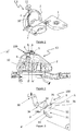
- the figure 2 presents an example of a supply assembly E2 according to the invention comprising chutes for filling fuel 5 and reducing agent 6 of the SCR catalytic reduction system (hereinafter “SCR agent”), these chutes 5 and 6 being connected together by a support piece 100 in greater detail with reference to figure 3 .
- the plane "P" in which the support part 100 extends overall, is perpendicular to the axes AA 'and BB' of the chutes 5 and 6 and is the section plane of the figure 4 .
- the support part 100 of the "W" profile comprises, as illustrated on figure 3 , a retaining plate 34 extended, on one side, by a fixing lug 30 of the SCR agent chute 6 (cf. figure 2 ) on an internal body wall (not visible) and, on an opposite side, by a "C” clip 31 for fixing the fuel channel 5.
- the plate 34 has screw holes 3V to hold the SCR agent chute 6 on the underside 34b of this plate 34 and the clamp 31 is formed of two arms 32 and 33, and extends in the plane " P ”around the fuel spout 5 (cf. figure 2 ) perpendicular to the axis A'A thereof, so that the axis of the clamp 31 coincides with the axis A'A.
- the arm 32 of the clamp 31 has on one end zone an extension in the form of a flat tongue 35, parallel to the “P” plane.
- the extension 35 is provided with a pin 51, of axis X'X parallel to the axis A'A of the clamp 31 (this axis X'X also being considered hereinafter as the axis of extension 35).
- the pin 51 is mounted on a circular support 36 and is intended to block the clamp 31, as will be explained in detail below.
- the support piece 100 is made of sheet metal and its thickness can vary from 1 mm to 3 mm between its fixing lug 30, the retaining plate 34 and the clamp 31.
- the arms 32 and 33 of the "C" clamp 31 are 1 to 1.5 mm thick, and the holding plate 34 is 2 mm thick.
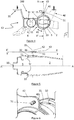
- the figure 4 shows a sectional view of the power supply assembly E2 along the plane P of the figure 2 .
- the SCR agent chute 6 is mounted on the plate 34 of the support part 100 and is equipped (respectively the fuel chute 5) with the lug 30 (respectively the lug 40) for fixing on the internal walls of the body of the motor vehicle (not shown).
- the fixing lug 40 is provided with a lug 42 provided with an orifice 43 which the pin 51 of the extension 35 formed at the end of the arm 32 of the clamp 31 passes through forcefully. said X'X and Y'Y of securing, respectively of the pin 51 and of the orifice 43, then come into coincidence.
- the figure 5 shows a sectional view of the power supply assembly E2 along the plane VV 'of the figure 4 .
- the plane VV ' contains the axis A'A of the fuel chute 5 and passes through the extension 35 of the arm 32, the lug 42 of the fixing lug 40 (cf. figure 4 ), the pin 51 of the extension 35 and its circular support 36.
- the fuel channel 5 is shown in section, with its plug 50 and its beginning of the pipe 2.
- the two arms 32 and 33 of the "C" clamp 31 enclose the chute 5 and the pin 51 of the extension 35 is inserted by force into the orifice 43 of the ear 42.
- the pin 51 is also glued in the orifice 43 to strengthen its connection with the ear 42 .
- the view of the figure 6 shows in perspective the detail of the connection between the lug 42 and the pin 51.
- the extension 35 of the clamp arm 32 (cf. figure 5 ) matches the circular contour portion 42c of the ear 42 and that the pin 51 is centered on this circular contour portion 42c.
- the SCR agent chute 6 is fixed to the plate 34 of the support part 100 and the clamp 31 of this support part 100 is mounted by spacing its arms 32, 33 on a constriction 5r ( figure 5 ) from the fuel filler neck 5.
- the clamp is then translated (arrow T1, figure 5 ) along the axis A'A of the fuel chute 5, until the extension 35 of the clamp arm 32 comes against the lug 42 to be secured to this lug 42 by the pin 51 along so-called X'X and Y'Y solidarization axes in coincidence.
- the invention is not limited to the embodiments described and shown. Thus it can concern more than two reservoirs.
- the support plate of the reducing agent chute can be flat or semi-cylindrical to adopt the shape of this chute.
- the fastening means integral with the ear and the extension as elements to be joined can be, in addition to the pin and the orifice, a means of clipping one element into an orifice of the other. element, a screw and threads formed in holes formed in the elements, a bolt passing through holes formed in the elements, or equivalent means.
- the clamp around the first chute has a hinge which closes with a locking means around the entire periphery of the first chute.
Landscapes
- Engineering & Computer Science (AREA)
- Chemical & Material Sciences (AREA)
- Combustion & Propulsion (AREA)
- Mechanical Engineering (AREA)
- Chemical Kinetics & Catalysis (AREA)
- General Engineering & Computer Science (AREA)
- Life Sciences & Earth Sciences (AREA)
- Sustainable Development (AREA)
- Sustainable Energy (AREA)
- Transportation (AREA)
- Health & Medical Sciences (AREA)
- Toxicology (AREA)
- Cooling, Air Intake And Gas Exhaust, And Fuel Tank Arrangements In Propulsion Units (AREA)
Description
- L'invention se rapporte à un ensemble d'alimentation de réservoirs de fluides muni de goulottes de remplissage solidarisées et à un procédé de montage de cet ensemble.
- L'invention concerne les réservoirs de fluides consommables dans un véhicule automobile, et plus particulièrement un réservoir de carburant et un réservoir d'agent réducteur pour un système de réduction catalytique dit SCR (acronyme de « selective catalytic réduction » en terminologie anglaise). La technologie SCR permet de respecter les normes de dépollution en vigueur, qui exigent un taux réduit d'émission des oxydes d'azote « NOX » proche de celui des moteurs à essence. Dans le cadre de cette technologie, une injection continue d'agent réducteur est effectuée dans la ligne d'échappement des NOX émis par le moteur et cette injection nécessite la mise en place d'un réservoir d'agent réducteur.
- Chacun des réservoirs de carburant et d'agent réducteur dispose de sa propre tubulure reliée à une goulotte de remplissage. Chaque goulotte est agencée dans un endroit d'accès facile pour l'utilisateur du véhicule automobile, en général dans la trappe de remplissage placée sur une façade latérale de la carrosserie.
- La
figure 1 présente un exemple de réalisation d'un tel ensemble « E1 » à double réservoir. Sur cettefigure 1 , le réservoir de carburant 1 est relié à la trappe 11 via la tubulure 2, et le réservoir d'agent réducteur 3 est relié à la trappe 11 via la tubulure 4. La trappe 11 est placée sur un côté latéral de la carrosserie d'un véhicule automobile, au-dessus du coffrage 10 d'une roue arrière. - La trappe de remplissage de l'agent réducteur est en général intégrée à la trappe 11 de la goulotte de carburant, ou constitue une trappe voisine, car les normes anti-pollution devenant de plus en plus contraignantes, le réservoir d'agent réducteur doit être rempli de plus en plus fréquemment. Le réservoir d'agent réducteur 3 et sa tubulure 4 étant en général de plus petite taille que respectivement le réservoir 1 et à la tubulure 2 du carburant, la tubulure d'agent réducteur 4 est dimensionnée en conséquence. Pour éviter un risque de casse au cours de l'opération de montage de l'ensemble d'alimentation des réservoirs dans le véhicule automobile appelée coiffage, cette tubulure 4 est couplée à la tubulure 2 du carburant à l'endroit, situé à proximité de la trappe 11, où les deux tubulures 2 et 4 se rapprochent l'une de l'autre.
- De nombreuses solutions ont contribué à améliorer cet ensemble de réservoirs et leur procédé de montage. Par exemple, le document
FR 3 034 052 - L'invention vise à s'affranchir de cet inconvénient et, pour ce faire, l'invention prévoit de supprimer le degré de liberté de rotation autour de la goulotte de plus faible résistance mécanique par une solidarisation de blocage entre les goulottes.
- A cet effet, la présente invention a pour objet un procédé de montage des goulottes de carburant et d'agent SCR d'un ensemble d'alimentation de réservoirs de carburant et d'agent tel que l'ensemble d'alimentation comporte des tubulures reliant le premier réservoir de carburant à une première goulotte de remplissage et le deuxième réservoir d'agent SCR à une deuxième goulotte de remplissage, chaque goulotte étant équipée d'une patte de fixation sur une paroi interne de carrosserie d'un véhicule automobile, et une pièce support qui intègre la patte de fixation de la deuxième goulotte et relie la deuxième goulotte à la première goulotte par une pince formée de deux bras s'étendant autour de la première goulotte dans un plan perpendiculaire à cette première goulotte, la patte de fixation de la première goulotte étant dotée d'une oreille reliée à une extension formée sur un bras de la pince par des moyens de fixation, l'oreille et l'extension s'étendant dans le plan de la pince, ledit procédé étant tel qu'il comporte les étapes suivantes :- la deuxième goulotte d'agent SCR est fixée à la pièce support et la pince de cette pièce support est montée par écartement de ses bras sur un rétrécissement de la première goulotte de remplissage de carburant ;- l'extension du bras de la pince est positionnée en alignement avec une oreille de la patte de fixation de la première goulotte par rotation de la pince de sorte que des axes de solidarisation de l'extension et de l'oreille viennent en coïncidence, ledit procédé étant caractérisé en ce qu'il comporte l'étape suivante: - la pince est translatée le long de l'axe de la première goulotte jusqu'à ce que l'extension du bras de pince vienne contre l'oreille de la patte de fixation de la première goulotte pour être solidarisée à cette oreille par des moyens de fixation le long des axes de solidarisation.
- Avantageusement, la deuxième goulotte peut avantageusement alimenter un agent réducteur pour un système de réduction catalytique SCR dans le cadre de l'invention.
- Selon un autre avantage:
- les moyens de fixation solidaires de l'oreille et de l'extension en tant qu'éléments à solidariser peuvent comporter un pion cylindrique venant d'un élément dans un orifice de l'autre élément;
- la pièce support peut être en matériau choisi entre une tôle, un acier et un alliage métallique, en particulier un alliage d'aluminium ou de titane ;
- l'épaisseur de la tôle peut être comprise entre 1 mm et 3 mm ;
- le pion cylindrique peut être en matériau plastique ;
- la pince autour de la première goulotte peut être une pince en « C » qui se clipse en force sur le pourtour de la première goulotte.
- Avantageusement, un véhicule automobile peut être équipé d'un ensemble d'alimentation d'au moins deux réservoirs de fluides consommables tel que défini ci-dessus.
- Après la dernière étape du procédé de l'invention ci-dessus, l'ensemble d'alimentation de deux réservoirs est installé dans le véhicule automobile par une opération de coiffage.
- Sur les figures, des éléments identiques ou analogues sont repérés par un même signe de référence qui renvoie au(x) passage(s) de la description qui le mentionne(nt).
- D'autres données, caractéristiques et avantages de la présente invention apparaîtront à la lecture de la description non limitée qui suit, en référence aux figures annexées qui représentent, respectivement :
- la
figure 1 , un ensemble d'alimentation de réservoirs de fluides selon l'état de la technique (déjà commentée) ; - la
figure 2 , la vue frontale d'un exemple d'ensemble d'alimentation de réservoirs de fluides selon l'invention ; - la
figure 3 , une vue en perspective de la pièce support des goulottes; - la
figure 4 , une vue en coupe de l'ensemble d'alimentation selon le plan « P » de lafigure 2 ; - la
figure 5 , une vue en coupe de l'ensemble d'alimentation selon le plan CC' de lafigures 4 ; et - la
figure 6 , un détail montrant, fixés par un pion, l'oreille de la patte de fixation de la première goulotte et l'extension formée sur un bras de la pince. - La
figure 2 présente un exemple d'ensemble d'alimentation E2 selon l'invention comportant des goulottes de remplissage de carburant 5 et d'agent réducteur 6 du système de réduction catalytique SCR (ci-après « agent SCR »), ces goulottes 5 et 6 étant reliées ensemble par une pièce support 100 plus amplement détaillée en référence à lafigure 3 . Le plan « P », dans lequel s'étend globalement la pièce support 100, est perpendiculaire aux axes AA' et BB' des goulottes 5 et 6 et est le plan de coupe de lafigure 4 . - En référence à la
figure 2 , il apparaît que les goulottes de carburant 5 et d'agent SCR 6 sont prolongées par des tubulures respectivement 2 et 4 qui relient les goulottes 5 et 6 aux réservoirs correspondants (non représentés) le long du coffrage de roue arrière 10. - La pièce support 100 de profil en « W » comporte, telle qu'illustrée à la
figure 3 , une plaque de maintien 34 prolongée, d'un côté, par une patte de fixation 30 de la goulotte d'agent SCR 6 (cf.figure 2 ) sur une paroi interne de carrosserie (non visible) et, d'un côté opposé, par une pince en « C » 31 de fixation de la goulotte de carburant 5. - La plaque 34 présente des orifices 3V de passage de vis pour maintenir la goulotte d'agent SCR 6 sur la face inférieure 34b de cette plaque 34 et la pince 31 est formée de deux bras 32 et 33, et s'étend dans le plan « P » autour de la goulotte de carburant 5 (cf.
figure 2 ) perpendiculairement à l'axe A'A de celle-ci, de sorte que l'axe de la pince 31 coïncide avec l'axe A'A. De plus, le bras 32 de la pince 31 présente sur une zone d'extrémité une extension en forme de langue plane 35, parallèle au plan « P ». En vue de la solidarisation des goulottes 5 et 6, l'extension 35 est munie d'un pion 51, d'axe X'X parallèle à l'axe A'A de la pince 31 (cet axe X'X étant également considéré ci-après comme l'axe de l'extension 35). Le pion 51 est monté sur un support circulaire 36 et est destiné à bloquer la pince 31, comme cela sera expliqué de manière détaillé ci-dessous. - La pièce support 100 est en tôle et son épaisseur peut varier de 1 mm à 3 mm entre sa patte de fixation 30, la plaque de maintien 34 et la pince 31. Dans cet exemple, les bras 32 et 33 de la pince en « C » 31 ont une épaisseur de 1 à 1,5 mm, et la plaque de maintien 34 une épaisseur de 2 mm.
- La
figure 4 présente une vue en coupe de l'ensemble d'alimentation E2 selon le plan P de lafigure 2 . La goulotte d'agent SCR 6 est montée sur la plaque 34 de la pièce support 100 et est équipée (respectivement la goulotte de carburant 5) de la patte 30 (respectivement de la patte 40) de fixation sur des parois internes de la carrosserie du véhicule automobile (non représentées). De plus, la patte de fixation 40 est munie d'une oreille 42 dotée d'un orifice 43 que traverse en force le pion 51 de l'extension 35 formée en extrémité du bras 32 de la pince 31. Les axes dits de solidarisation X'X et Y'Y, respectivement du pion 51 et de l'orifice 43, viennent alors en coïncidence. - Dans ces conditions, les tubulures 2 et 4 des goulottes 5 et 6 sont bien solidarisées entre elles avant l'opération de coiffage, par blocage des degrés de liberté de mouvement de la pince en « C » 31 que ce soit dans le plan « P » et/ou selon un axe A'A (cf.
figures 3 ou5 ) perpendiculaire à ce plan. Les risques d'affaissement ou de casse de la tubulure d'agent SCR 6, la plus fragile des deux tubulures, sont ainsi supprimés. - La
figure 5 présente une vue en coupe de l'ensemble d'alimentation E2 selon le plan V-V' de lafigure 4 . Le plan V-V' contient l'axe A'A de la goulotte de carburant 5 et traverse l'extension 35 du bras 32, l'oreille 42 de la patte de fixation 40 (cf.figure 4 ), le pion 51 de l'extension 35 et son support circulaire 36. La goulotte de carburant 5 est présentée en coupe, avec son bouchon 50 et son début de tubulure 2. Les deux bras 32 et 33 de la pince en « C » 31 enserrent la goulotte 5 et le pion 51 de l'extension 35 est inséré en force dans l'orifice 43 de l'oreille 42. Avantageusement le pion 51 est également collé dans l'orifice 43 pour renforcer sa liaison avec l'oreille 42. - Plus précisément, la vue de la
figure 6 présente en perspective le détail de la liaison entre l'oreille 42 et le pion 51. Sur cette figure, il apparaît que l'extension 35 du bras de pince 32 (cf.figure 5 ) épouse la portion de contour circulaire 42c de l'oreille 42 et que le pion 51 est centré sur cette portion de contour circulaire 42c. - Par ailleurs, le montage des goulottes de carburant 5 et d'agent SCR 6 de cet exemple d'ensemble d'alimentation peut être mis en œuvre selon les étapes suivantes, en référence aux
figures 4 et 5 . - La goulotte d'agent SCR 6 est fixée à la plaque 34 de la pièce support 100 et la pince 31 de cette pièce support 100 est montée par écartement de ses bras 32, 33 sur un rétrécissement 5r (
figure 5 ) de la goulotte de carburant 5. - Puis, par rotation (flèche double R1,
figure 4 ) de la pince 31 dans le rétrécissement 5r, l'axe X'X de l'extension de bras 35 est amenée en alignement et donc en coïncidence=avec l'axe Y'Y de l'orifice 43 de l'oreille 42 de la patte de fixation 40 de la goulotte de carburant 5. - La pince est alors translatée (flèche T1,
figure 5 ) le long de l'axe A'A de la goulotte de carburant 5, jusqu'à ce que l'extension 35 du bras de pince 32 vienne contre l'oreille 42 pour être solidarisée à cette oreille 42 par le pion 51 le long des axes dits de solidarisation X'X et Y'Y en coïncidence. - L'invention n'est pas limitée aux exemples de réalisation décrits et représentés. Ainsi elle peut concerner plus de deux réservoirs. La plaque support de la goulotte d'agent réducteur peut être plate ou semi-cylindrique pour adopter la forme de cette goulotte.
- En outre, les moyens de fixation solidaires de l'oreille et de l'extension en tant qu'éléments à solidariser peuvent être, outre le pion et l'orifice, un moyen de clipsage d'un élément dans un orifice de l'autre élément, une vis et des taraudages formés dans des orifices formés dans les éléments, un boulon traversant des orifices formés dans les éléments, ou des moyens équivalents.
- Par ailleurs, la pince autour de la première goulotte présente une charnière qui se referme avec un moyen de verrouillage sur le pourtour complet de la première goulotte.
Claims (2)
- Procédé de montage des goulottes (5, 6) de carburant et d'agent SCR d'un ensemble d'alimentation (E2) de réservoirs de carburant et d'agent SCR tel que l'ensemble d'alimentation (E2) comporte des tubulures (2, 4) reliant le premier réservoir de carburant (1) à une première goulotte de remplissage (5) et le deuxième réservoir d'agent SCR (3) à une deuxième goulotte de remplissage (6), chaque goulotte (5, 6) étant équipée d'une patte de fixation (30, 40) sur une paroi interne de carrosserie d'un véhicule automobile, et une pièce support (100) qui intègre la patte de fixation (30) de la deuxième goulotte (6) et relie la deuxième goulotte (6) à la première goulotte (5) par une pince (31) formée de deux bras (32, 33) s'étendant autour de la première goulotte (5) dans un plan perpendiculaire (P) à cette première goulotte (5), la patte de fixation (40) de la première goulotte (5) étant dotée d'une oreille (42) reliée à une extension (35) formée sur un bras (32) de la pince (31) par des moyens de fixation (51), l'oreille (42) et l'extension (35) s'étendant dans le plan (P) de la pince (31), ledit procédé étant tel qu'il comporte les étapes suivantes :- la deuxième goulotte d'agent SCR (6) est fixée à la pièce support (100) et la pince (31) de cette pièce support (100) est montée par écartement de ses bras (32, 33) sur un rétrécissement (5r) de la première goulotte de remplissage (5) de carburant ;- l'extension (35) du bras (32) de la pince (31) est positionnée en alignement avec une oreille (42) de la patte de fixation (40) de la première goulotte (5) par rotation (R1) de la pince (31) de sorte que des axes de solidarisation (X'X, Y'Y) de l'extension (35) et de l'oreille (42) viennent en coïncidence, ledit procédé étant caractérisé en ce qu'il comporte l'étape suivante:- la pince (31) est translatée le long de l'axe de la première goulotte (5) jusqu'à ce que l'extension (35) du bras (32) de pince (31) vienne contre l'oreille (42) de la patte de fixation (40) de la première goulotte (5) pour être solidarisée à cette oreille (42) par des moyens de fixation (51) le long des axes de solidarisation (X'X, Y'Y).
- Procédé de montage selon la revendication précédente, dans lequel l'ensemble d'alimentation (E2) est installé dans le véhicule automobile par une opération de coiffage.
Applications Claiming Priority (1)
| Application Number | Priority Date | Filing Date | Title |
|---|---|---|---|
| FR1757988A FR3070324B1 (fr) | 2017-08-30 | 2017-08-30 | Ensemble d’alimentation de reservoirs de fluides et procede de montage de cet ensemble |
Publications (2)
| Publication Number | Publication Date |
|---|---|
| EP3450237A1 EP3450237A1 (fr) | 2019-03-06 |
| EP3450237B1 true EP3450237B1 (fr) | 2021-02-24 |
Family
ID=59974686
Family Applications (1)
| Application Number | Title | Priority Date | Filing Date |
|---|---|---|---|
| EP18184895.3A Active EP3450237B1 (fr) | 2017-08-30 | 2018-07-23 | Ensemble d'alimentation de réservoirs de fluides et procédé de montage de cet ensemble |
Country Status (2)
| Country | Link |
|---|---|
| EP (1) | EP3450237B1 (fr) |
| FR (1) | FR3070324B1 (fr) |
Family Cites Families (3)
| Publication number | Priority date | Publication date | Assignee | Title |
|---|---|---|---|---|
| JPH10271646A (ja) * | 1997-03-21 | 1998-10-09 | Nissan Motor Co Ltd | ワイヤーハーネス固定用ホルダークリップ |
| DE102011115144A1 (de) * | 2011-09-27 | 2013-03-28 | Veritas Ag | Einfüllvorrichtung |
| FR3034052B1 (fr) * | 2015-03-27 | 2017-03-31 | Peugeot Citroen Automobiles Sa | Ensemble de reservoirs de fluides consommables pour vehicule automobile |
-
2017
- 2017-08-30 FR FR1757988A patent/FR3070324B1/fr not_active Expired - Fee Related
-
2018
- 2018-07-23 EP EP18184895.3A patent/EP3450237B1/fr active Active
Non-Patent Citations (1)
| Title |
|---|
| None * |
Also Published As
| Publication number | Publication date |
|---|---|
| FR3070324B1 (fr) | 2019-09-13 |
| EP3450237A1 (fr) | 2019-03-06 |
| FR3070324A1 (fr) | 2019-03-01 |
Similar Documents
| Publication | Publication Date | Title |
|---|---|---|
| EP3274206B1 (fr) | Ensemble de réservoirs de fluides consommables pour véhicule automobile | |
| FR3070324B1 (fr) | Ensemble d’alimentation de reservoirs de fluides et procede de montage de cet ensemble | |
| EP2062804B1 (fr) | Dispositif et procédé de fixation d'un ensemble d'aile sur une paroi de caisse d'un véhicule automobile | |
| EP2554481B1 (fr) | Dispositif de liaison plus particulièrement adapté pour assurer la liaison entre une entrée d'air et une motorisation d'une nacelle d'aéronef | |
| FR2925430A1 (fr) | Peau de pare-chocs amelioree | |
| WO2012117189A1 (fr) | Vehicule comportant un absorbeur de choc et absorbeur de choc correspondant | |
| FR3145738A1 (fr) | Mécanisme à crémaillère de direction, traverse transversale pour berceau, ensemble de véhicule automobile et véhicule automobile comportant un tel ensemble | |
| EP2289790B1 (fr) | Protège-main pour poignée de guidon de motocyclette | |
| EP2260226A2 (fr) | Joint imperdable pour raccord banjo et ensemble comportant un raccord banjo et un tel joint | |
| EP3609729B1 (fr) | Ensemble de deux reservoirs de fluide avec goulottes solidarisees | |
| WO2016038265A1 (fr) | Véhicule automobile a ligne d'échappement courte et écran de protection thermique du réservoir de carburant de ce véhicule | |
| WO2016038266A1 (fr) | Vehicule automobile a ligne d'echappement courte et ecran de protection thermique du reservoir de carburant de ce vehicule | |
| FR2957650A1 (fr) | Agrafe de fixation pour cables ou tubes | |
| WO2020157414A1 (fr) | Vehicule comprenant un support d'enjoliveur de vitre assemble par clinchage | |
| FR2882091A1 (fr) | Agencement d'un element de raccord coude comportant une plaque de fixation et une coquille dans un circuit d'echappement de moteur a combustion | |
| EP3299262B1 (fr) | Caisse de vehicule automobile a panier de rangement d'une roue de secours et pourvu d'un ecran de protection thermique | |
| EP1849664A2 (fr) | Dispositif de sécurité passif en cas de choc piéton avant d'un véhicule automobile et véhicule comprenant un tel dispositif | |
| EP3672822B1 (fr) | Ensemble d'une goulotte de carburant et d'une goulotte d'un agent liquide solidarisees ensemble | |
| FR2865990A1 (fr) | Traverse pour vehicule automobile comprenant un organe interieur de renfort. | |
| FR2981692A1 (fr) | Systeme d echappement d un vehicule automobile | |
| FR2926852A1 (fr) | Ensemble moteur pour un vehicule automobile et vehicule automobile comprenant un tel ensemble moteur | |
| EP1637747B1 (fr) | Agencement de fixation d'un élèment d'équipement pour véhicule automobile | |
| EP2375048B1 (fr) | Dispositif de répartiteur d'admission intégrant des platines et son procédé de montage sur un moteur | |
| EP3847049A1 (fr) | Dispositif de liaison entre tetes de tubulure de reservoirs et vehicule automobile equipe d'un tel dispositif | |
| EP1790561B1 (fr) | Structure d'un arbre d'une partie de pivotement d'un véhicule |
Legal Events
| Date | Code | Title | Description |
|---|---|---|---|
| PUAI | Public reference made under article 153(3) epc to a published international application that has entered the european phase |
Free format text: ORIGINAL CODE: 0009012 |
|
| STAA | Information on the status of an ep patent application or granted ep patent |
Free format text: STATUS: THE APPLICATION HAS BEEN PUBLISHED |
|
| AK | Designated contracting states |
Kind code of ref document: A1 Designated state(s): AL AT BE BG CH CY CZ DE DK EE ES FI FR GB GR HR HU IE IS IT LI LT LU LV MC MK MT NL NO PL PT RO RS SE SI SK SM TR |
|
| AX | Request for extension of the european patent |
Extension state: BA ME |
|
| STAA | Information on the status of an ep patent application or granted ep patent |
Free format text: STATUS: REQUEST FOR EXAMINATION WAS MADE |
|
| 17P | Request for examination filed |
Effective date: 20190902 |
|
| RBV | Designated contracting states (corrected) |
Designated state(s): AL AT BE BG CH CY CZ DE DK EE ES FI FR GB GR HR HU IE IS IT LI LT LU LV MC MK MT NL NO PL PT RO RS SE SI SK SM TR |
|
| GRAP | Despatch of communication of intention to grant a patent |
Free format text: ORIGINAL CODE: EPIDOSNIGR1 |
|
| STAA | Information on the status of an ep patent application or granted ep patent |
Free format text: STATUS: GRANT OF PATENT IS INTENDED |
|
| RAP1 | Party data changed (applicant data changed or rights of an application transferred) |
Owner name: PSA AUTOMOBILES SA |
|
| INTG | Intention to grant announced |
Effective date: 20201028 |
|
| GRAS | Grant fee paid |
Free format text: ORIGINAL CODE: EPIDOSNIGR3 |
|
| GRAA | (expected) grant |
Free format text: ORIGINAL CODE: 0009210 |
|
| STAA | Information on the status of an ep patent application or granted ep patent |
Free format text: STATUS: THE PATENT HAS BEEN GRANTED |
|
| AK | Designated contracting states |
Kind code of ref document: B1 Designated state(s): AL AT BE BG CH CY CZ DE DK EE ES FI FR GB GR HR HU IE IS IT LI LT LU LV MC MK MT NL NO PL PT RO RS SE SI SK SM TR |
|
| REG | Reference to a national code |
Ref country code: CH Ref legal event code: EP |
|
| REG | Reference to a national code |
Ref country code: DE Ref legal event code: R084 Ref document number: 602018012928 Country of ref document: DE |
|
| REG | Reference to a national code |
Ref country code: AT Ref legal event code: REF Ref document number: 1364006 Country of ref document: AT Kind code of ref document: T Effective date: 20210315 |
|
| REG | Reference to a national code |
Ref country code: IE Ref legal event code: FG4D Free format text: LANGUAGE OF EP DOCUMENT: FRENCH |
|
| REG | Reference to a national code |
Ref country code: DE Ref legal event code: R096 Ref document number: 602018012928 Country of ref document: DE |
|
| REG | Reference to a national code |
Ref country code: GB Ref legal event code: 746 Effective date: 20210614 |
|
| REG | Reference to a national code |
Ref country code: LT Ref legal event code: MG9D |
|
| REG | Reference to a national code |
Ref country code: NL Ref legal event code: MP Effective date: 20210224 |
|
| PG25 | Lapsed in a contracting state [announced via postgrant information from national office to epo] |
Ref country code: FI Free format text: LAPSE BECAUSE OF FAILURE TO SUBMIT A TRANSLATION OF THE DESCRIPTION OR TO PAY THE FEE WITHIN THE PRESCRIBED TIME-LIMIT Effective date: 20210224 Ref country code: GR Free format text: LAPSE BECAUSE OF FAILURE TO SUBMIT A TRANSLATION OF THE DESCRIPTION OR TO PAY THE FEE WITHIN THE PRESCRIBED TIME-LIMIT Effective date: 20210525 Ref country code: HR Free format text: LAPSE BECAUSE OF FAILURE TO SUBMIT A TRANSLATION OF THE DESCRIPTION OR TO PAY THE FEE WITHIN THE PRESCRIBED TIME-LIMIT Effective date: 20210224 Ref country code: BG Free format text: LAPSE BECAUSE OF FAILURE TO SUBMIT A TRANSLATION OF THE DESCRIPTION OR TO PAY THE FEE WITHIN THE PRESCRIBED TIME-LIMIT Effective date: 20210524 Ref country code: LT Free format text: LAPSE BECAUSE OF FAILURE TO SUBMIT A TRANSLATION OF THE DESCRIPTION OR TO PAY THE FEE WITHIN THE PRESCRIBED TIME-LIMIT Effective date: 20210224 Ref country code: PT Free format text: LAPSE BECAUSE OF FAILURE TO SUBMIT A TRANSLATION OF THE DESCRIPTION OR TO PAY THE FEE WITHIN THE PRESCRIBED TIME-LIMIT Effective date: 20210624 Ref country code: NO Free format text: LAPSE BECAUSE OF FAILURE TO SUBMIT A TRANSLATION OF THE DESCRIPTION OR TO PAY THE FEE WITHIN THE PRESCRIBED TIME-LIMIT Effective date: 20210524 |
|
| REG | Reference to a national code |
Ref country code: AT Ref legal event code: MK05 Ref document number: 1364006 Country of ref document: AT Kind code of ref document: T Effective date: 20210224 |
|
| PG25 | Lapsed in a contracting state [announced via postgrant information from national office to epo] |
Ref country code: RS Free format text: LAPSE BECAUSE OF FAILURE TO SUBMIT A TRANSLATION OF THE DESCRIPTION OR TO PAY THE FEE WITHIN THE PRESCRIBED TIME-LIMIT Effective date: 20210224 Ref country code: NL Free format text: LAPSE BECAUSE OF FAILURE TO SUBMIT A TRANSLATION OF THE DESCRIPTION OR TO PAY THE FEE WITHIN THE PRESCRIBED TIME-LIMIT Effective date: 20210224 Ref country code: LV Free format text: LAPSE BECAUSE OF FAILURE TO SUBMIT A TRANSLATION OF THE DESCRIPTION OR TO PAY THE FEE WITHIN THE PRESCRIBED TIME-LIMIT Effective date: 20210224 Ref country code: PL Free format text: LAPSE BECAUSE OF FAILURE TO SUBMIT A TRANSLATION OF THE DESCRIPTION OR TO PAY THE FEE WITHIN THE PRESCRIBED TIME-LIMIT Effective date: 20210224 Ref country code: SE Free format text: LAPSE BECAUSE OF FAILURE TO SUBMIT A TRANSLATION OF THE DESCRIPTION OR TO PAY THE FEE WITHIN THE PRESCRIBED TIME-LIMIT Effective date: 20210224 |
|
| PG25 | Lapsed in a contracting state [announced via postgrant information from national office to epo] |
Ref country code: IS Free format text: LAPSE BECAUSE OF FAILURE TO SUBMIT A TRANSLATION OF THE DESCRIPTION OR TO PAY THE FEE WITHIN THE PRESCRIBED TIME-LIMIT Effective date: 20210624 |
|
| PG25 | Lapsed in a contracting state [announced via postgrant information from national office to epo] |
Ref country code: EE Free format text: LAPSE BECAUSE OF FAILURE TO SUBMIT A TRANSLATION OF THE DESCRIPTION OR TO PAY THE FEE WITHIN THE PRESCRIBED TIME-LIMIT Effective date: 20210224 Ref country code: CZ Free format text: LAPSE BECAUSE OF FAILURE TO SUBMIT A TRANSLATION OF THE DESCRIPTION OR TO PAY THE FEE WITHIN THE PRESCRIBED TIME-LIMIT Effective date: 20210224 Ref country code: SM Free format text: LAPSE BECAUSE OF FAILURE TO SUBMIT A TRANSLATION OF THE DESCRIPTION OR TO PAY THE FEE WITHIN THE PRESCRIBED TIME-LIMIT Effective date: 20210224 Ref country code: AT Free format text: LAPSE BECAUSE OF FAILURE TO SUBMIT A TRANSLATION OF THE DESCRIPTION OR TO PAY THE FEE WITHIN THE PRESCRIBED TIME-LIMIT Effective date: 20210224 |
|
| REG | Reference to a national code |
Ref country code: DE Ref legal event code: R097 Ref document number: 602018012928 Country of ref document: DE |
|
| PG25 | Lapsed in a contracting state [announced via postgrant information from national office to epo] |
Ref country code: RO Free format text: LAPSE BECAUSE OF FAILURE TO SUBMIT A TRANSLATION OF THE DESCRIPTION OR TO PAY THE FEE WITHIN THE PRESCRIBED TIME-LIMIT Effective date: 20210224 Ref country code: DK Free format text: LAPSE BECAUSE OF FAILURE TO SUBMIT A TRANSLATION OF THE DESCRIPTION OR TO PAY THE FEE WITHIN THE PRESCRIBED TIME-LIMIT Effective date: 20210224 Ref country code: SK Free format text: LAPSE BECAUSE OF FAILURE TO SUBMIT A TRANSLATION OF THE DESCRIPTION OR TO PAY THE FEE WITHIN THE PRESCRIBED TIME-LIMIT Effective date: 20210224 |
|
| PLBE | No opposition filed within time limit |
Free format text: ORIGINAL CODE: 0009261 |
|
| STAA | Information on the status of an ep patent application or granted ep patent |
Free format text: STATUS: NO OPPOSITION FILED WITHIN TIME LIMIT |
|
| PG25 | Lapsed in a contracting state [announced via postgrant information from national office to epo] |
Ref country code: ES Free format text: LAPSE BECAUSE OF FAILURE TO SUBMIT A TRANSLATION OF THE DESCRIPTION OR TO PAY THE FEE WITHIN THE PRESCRIBED TIME-LIMIT Effective date: 20210224 Ref country code: AL Free format text: LAPSE BECAUSE OF FAILURE TO SUBMIT A TRANSLATION OF THE DESCRIPTION OR TO PAY THE FEE WITHIN THE PRESCRIBED TIME-LIMIT Effective date: 20210224 |
|
| 26N | No opposition filed |
Effective date: 20211125 |
|
| PG25 | Lapsed in a contracting state [announced via postgrant information from national office to epo] |
Ref country code: SI Free format text: LAPSE BECAUSE OF FAILURE TO SUBMIT A TRANSLATION OF THE DESCRIPTION OR TO PAY THE FEE WITHIN THE PRESCRIBED TIME-LIMIT Effective date: 20210224 |
|
| REG | Reference to a national code |
Ref country code: CH Ref legal event code: PL |
|
| PG25 | Lapsed in a contracting state [announced via postgrant information from national office to epo] |
Ref country code: MC Free format text: LAPSE BECAUSE OF FAILURE TO SUBMIT A TRANSLATION OF THE DESCRIPTION OR TO PAY THE FEE WITHIN THE PRESCRIBED TIME-LIMIT Effective date: 20210224 |
|
| REG | Reference to a national code |
Ref country code: BE Ref legal event code: MM Effective date: 20210731 |
|
| PG25 | Lapsed in a contracting state [announced via postgrant information from national office to epo] |
Ref country code: LI Free format text: LAPSE BECAUSE OF NON-PAYMENT OF DUE FEES Effective date: 20210731 Ref country code: IT Free format text: LAPSE BECAUSE OF FAILURE TO SUBMIT A TRANSLATION OF THE DESCRIPTION OR TO PAY THE FEE WITHIN THE PRESCRIBED TIME-LIMIT Effective date: 20210224 Ref country code: CH Free format text: LAPSE BECAUSE OF NON-PAYMENT OF DUE FEES Effective date: 20210731 |
|
| PG25 | Lapsed in a contracting state [announced via postgrant information from national office to epo] |
Ref country code: IS Free format text: LAPSE BECAUSE OF FAILURE TO SUBMIT A TRANSLATION OF THE DESCRIPTION OR TO PAY THE FEE WITHIN THE PRESCRIBED TIME-LIMIT Effective date: 20210624 Ref country code: LU Free format text: LAPSE BECAUSE OF NON-PAYMENT OF DUE FEES Effective date: 20210723 |
|
| PG25 | Lapsed in a contracting state [announced via postgrant information from national office to epo] |
Ref country code: IE Free format text: LAPSE BECAUSE OF NON-PAYMENT OF DUE FEES Effective date: 20210723 Ref country code: BE Free format text: LAPSE BECAUSE OF NON-PAYMENT OF DUE FEES Effective date: 20210731 |
|
| PG25 | Lapsed in a contracting state [announced via postgrant information from national office to epo] |
Ref country code: CY Free format text: LAPSE BECAUSE OF FAILURE TO SUBMIT A TRANSLATION OF THE DESCRIPTION OR TO PAY THE FEE WITHIN THE PRESCRIBED TIME-LIMIT Effective date: 20210224 |
|
| PG25 | Lapsed in a contracting state [announced via postgrant information from national office to epo] |
Ref country code: HU Free format text: LAPSE BECAUSE OF FAILURE TO SUBMIT A TRANSLATION OF THE DESCRIPTION OR TO PAY THE FEE WITHIN THE PRESCRIBED TIME-LIMIT; INVALID AB INITIO Effective date: 20180723 |
|
| REG | Reference to a national code |
Ref country code: DE Ref legal event code: R081 Ref document number: 602018012928 Country of ref document: DE Owner name: STELLANTIS AUTO SAS, FR Free format text: FORMER OWNER: PSA AUTOMOBILES SA, POISSY, FR |
|
| PG25 | Lapsed in a contracting state [announced via postgrant information from national office to epo] |
Ref country code: MK Free format text: LAPSE BECAUSE OF FAILURE TO SUBMIT A TRANSLATION OF THE DESCRIPTION OR TO PAY THE FEE WITHIN THE PRESCRIBED TIME-LIMIT Effective date: 20210224 |
|
| PG25 | Lapsed in a contracting state [announced via postgrant information from national office to epo] |
Ref country code: TR Free format text: LAPSE BECAUSE OF FAILURE TO SUBMIT A TRANSLATION OF THE DESCRIPTION OR TO PAY THE FEE WITHIN THE PRESCRIBED TIME-LIMIT Effective date: 20210224 |
|
| PG25 | Lapsed in a contracting state [announced via postgrant information from national office to epo] |
Ref country code: MT Free format text: LAPSE BECAUSE OF FAILURE TO SUBMIT A TRANSLATION OF THE DESCRIPTION OR TO PAY THE FEE WITHIN THE PRESCRIBED TIME-LIMIT Effective date: 20210224 |
|
| PGFP | Annual fee paid to national office [announced via postgrant information from national office to epo] |
Ref country code: GB Payment date: 20250619 Year of fee payment: 8 |
|
| PGFP | Annual fee paid to national office [announced via postgrant information from national office to epo] |
Ref country code: FR Payment date: 20250620 Year of fee payment: 8 |
|
| PGFP | Annual fee paid to national office [announced via postgrant information from national office to epo] |
Ref country code: DE Payment date: 20250620 Year of fee payment: 8 |