EP3450179B1 - Machine et procédé d'impression directe destinés à l'impression de récipients par impression directe - Google Patents
Machine et procédé d'impression directe destinés à l'impression de récipients par impression directe Download PDFInfo
- Publication number
- EP3450179B1 EP3450179B1 EP18182166.1A EP18182166A EP3450179B1 EP 3450179 B1 EP3450179 B1 EP 3450179B1 EP 18182166 A EP18182166 A EP 18182166A EP 3450179 B1 EP3450179 B1 EP 3450179B1
- Authority
- EP
- European Patent Office
- Prior art keywords
- direct
- print head
- printing
- ink
- direct print
- Prior art date
- Legal status (The legal status is an assumption and is not a legal conclusion. Google has not performed a legal analysis and makes no representation as to the accuracy of the status listed.)
- Active
Links
- 238000007639 printing Methods 0.000 title claims description 109
- 238000010017 direct printing Methods 0.000 title claims description 83
- 238000000034 method Methods 0.000 title claims description 13
- 230000008878 coupling Effects 0.000 claims description 21
- 238000010168 coupling process Methods 0.000 claims description 21
- 238000005859 coupling reaction Methods 0.000 claims description 21
- 238000003860 storage Methods 0.000 claims description 20
- 230000005499 meniscus Effects 0.000 claims description 17
- 238000012423 maintenance Methods 0.000 claims description 12
- 239000002245 particle Substances 0.000 claims description 7
- 238000007872 degassing Methods 0.000 claims description 5
- 238000009826 distribution Methods 0.000 claims description 5
- 230000001105 regulatory effect Effects 0.000 claims description 4
- 238000004062 sedimentation Methods 0.000 claims description 2
- 239000000976 ink Substances 0.000 description 156
- 238000010926 purge Methods 0.000 description 5
- 235000013361 beverage Nutrition 0.000 description 4
- 238000010586 diagram Methods 0.000 description 4
- 238000007641 inkjet printing Methods 0.000 description 4
- 238000004140 cleaning Methods 0.000 description 3
- 239000003086 colorant Substances 0.000 description 3
- 238000011010 flushing procedure Methods 0.000 description 3
- 239000007789 gas Substances 0.000 description 3
- 238000005259 measurement Methods 0.000 description 3
- 230000019612 pigmentation Effects 0.000 description 3
- 238000010438 heat treatment Methods 0.000 description 2
- 239000007788 liquid Substances 0.000 description 2
- 238000004519 manufacturing process Methods 0.000 description 2
- 238000012545 processing Methods 0.000 description 2
- MKYBYDHXWVHEJW-UHFFFAOYSA-N N-[1-oxo-1-(2,4,6,7-tetrahydrotriazolo[4,5-c]pyridin-5-yl)propan-2-yl]-2-[[3-(trifluoromethoxy)phenyl]methylamino]pyrimidine-5-carboxamide Chemical compound O=C(C(C)NC(=O)C=1C=NC(=NC=1)NCC1=CC(=CC=C1)OC(F)(F)F)N1CC2=C(CC1)NN=N2 MKYBYDHXWVHEJW-UHFFFAOYSA-N 0.000 description 1
- 230000001276 controlling effect Effects 0.000 description 1
- 238000001035 drying Methods 0.000 description 1
- 238000011156 evaluation Methods 0.000 description 1
- 239000000945 filler Substances 0.000 description 1
- 238000005429 filling process Methods 0.000 description 1
- 230000009969 flowable effect Effects 0.000 description 1
- 239000012530 fluid Substances 0.000 description 1
- 239000011521 glass Substances 0.000 description 1
- 238000002372 labelling Methods 0.000 description 1
- 230000007257 malfunction Effects 0.000 description 1
- 239000002184 metal Substances 0.000 description 1
- 239000000203 mixture Substances 0.000 description 1
- 238000004806 packaging method and process Methods 0.000 description 1
- 239000000825 pharmaceutical preparation Substances 0.000 description 1
- 229940127557 pharmaceutical product Drugs 0.000 description 1
- 239000000049 pigment Substances 0.000 description 1
- 230000003068 static effect Effects 0.000 description 1
- 239000000126 substance Substances 0.000 description 1
- 238000011144 upstream manufacturing Methods 0.000 description 1
Images

Classifications
-
- B—PERFORMING OPERATIONS; TRANSPORTING
- B41—PRINTING; LINING MACHINES; TYPEWRITERS; STAMPS
- B41J—TYPEWRITERS; SELECTIVE PRINTING MECHANISMS, i.e. MECHANISMS PRINTING OTHERWISE THAN FROM A FORME; CORRECTION OF TYPOGRAPHICAL ERRORS
- B41J2/00—Typewriters or selective printing mechanisms characterised by the printing or marking process for which they are designed
- B41J2/005—Typewriters or selective printing mechanisms characterised by the printing or marking process for which they are designed characterised by bringing liquid or particles selectively into contact with a printing material
- B41J2/01—Ink jet
- B41J2/17—Ink jet characterised by ink handling
- B41J2/175—Ink supply systems ; Circuit parts therefor
- B41J2/17596—Ink pumps, ink valves
-
- B—PERFORMING OPERATIONS; TRANSPORTING
- B41—PRINTING; LINING MACHINES; TYPEWRITERS; STAMPS
- B41J—TYPEWRITERS; SELECTIVE PRINTING MECHANISMS, i.e. MECHANISMS PRINTING OTHERWISE THAN FROM A FORME; CORRECTION OF TYPOGRAPHICAL ERRORS
- B41J2/00—Typewriters or selective printing mechanisms characterised by the printing or marking process for which they are designed
- B41J2/005—Typewriters or selective printing mechanisms characterised by the printing or marking process for which they are designed characterised by bringing liquid or particles selectively into contact with a printing material
- B41J2/01—Ink jet
- B41J2/17—Ink jet characterised by ink handling
- B41J2/175—Ink supply systems ; Circuit parts therefor
-
- B—PERFORMING OPERATIONS; TRANSPORTING
- B41—PRINTING; LINING MACHINES; TYPEWRITERS; STAMPS
- B41J—TYPEWRITERS; SELECTIVE PRINTING MECHANISMS, i.e. MECHANISMS PRINTING OTHERWISE THAN FROM A FORME; CORRECTION OF TYPOGRAPHICAL ERRORS
- B41J2/00—Typewriters or selective printing mechanisms characterised by the printing or marking process for which they are designed
- B41J2/005—Typewriters or selective printing mechanisms characterised by the printing or marking process for which they are designed characterised by bringing liquid or particles selectively into contact with a printing material
- B41J2/01—Ink jet
- B41J2/17—Ink jet characterised by ink handling
- B41J2/18—Ink recirculation systems
-
- B—PERFORMING OPERATIONS; TRANSPORTING
- B41—PRINTING; LINING MACHINES; TYPEWRITERS; STAMPS
- B41J—TYPEWRITERS; SELECTIVE PRINTING MECHANISMS, i.e. MECHANISMS PRINTING OTHERWISE THAN FROM A FORME; CORRECTION OF TYPOGRAPHICAL ERRORS
- B41J3/00—Typewriters or selective printing or marking mechanisms characterised by the purpose for which they are constructed
- B41J3/407—Typewriters or selective printing or marking mechanisms characterised by the purpose for which they are constructed for marking on special material
- B41J3/4073—Printing on three-dimensional objects not being in sheet or web form, e.g. spherical or cubic objects
Definitions
- the invention relates to a direct printing machine and a direct printing method for printing containers with direct printing according to the features of the preamble of claims 1 and 12, respectively.
- containers such as beverage containers are provided with a label in a labeling machine in order to identify and / or advertise the container contents.
- Such direct printing machines usually comprise at least one stationary direct printing station with a direct printing head and a conveyor for transporting the containers past the at least one direct printing station.
- the containers With the conveyor, the containers are received, for example, in container receptacles and transported to the at least one stationary direct printing station. There the containers are rotated by means of the container receptacles and, in the process, printed with printing ink from a large number of printing nozzles using the direct print head.
- the print nozzles are controlled in such a way that the ink droplets dispensed onto the container produce the desired print image. If multi-colored direct printing is required, the containers are transported past several direct printing stations and printed there sequentially with printing inks of different colors.
- such direct printing machines comprise an ink supply system with a supply line for the printing ink in order to produce a flow of ink from a storage tank to the direct print head.
- the ink supply system optionally includes a return line for the printing ink in order to establish a flow of ink from the direct print head back to the supply tank. This keeps the printing ink in a continuous flow so that particles cannot settle in the printing ink.
- the DE 10 2013 217 679 A1 discloses a printing machine for inkjet printing on containers, comprising at least one stationary printing unit for printing the container and a filling station for printing ink assigned to the printing unit.
- the DE 10 2009 020 702 A1 discloses a printing system for printing bottles, with a print head which can be moved along a transport path for the containers and operates according to the inkjet principle for printing the respective container arranged at a printing position, as well as with a supply system for the print head with printing ink. Since the print head is with moves the bottle to be printed, it is proposed to divide the supply system into a static part and a moving part, the moving part having an auxiliary tank for the printing ink in addition to the print head in order to ensure high print quality.
- the disadvantage here is that during maintenance of the direct print head or during commissioning, the forward and / or return of the ink supply system has to be disconnected and, as a result, it is time-consuming to subsequently restore a closed ink flow. In addition, no automatic flushing of the ink supply system or the direct print head is possible.
- the US 2016/221346 A1 discloses a printing system and a printing device for bottles or containers with a multi-part storage tank.
- the US 2013/100205 A1 discloses an inkjet printing apparatus and method for draining a transport ink.
- the object of the present invention is therefore to provide an ink supply system for a direct printing machine with at least one stationary direct printing station and a transporter, in which the production of a closed ink flow is simplified and an automated flushing of the ink supply system or the direct print head is possible. It is also an object of the invention to reduce the number of ink pumps without impairing the print quality.
- the invention provides a direct printing machine with the features of claim 1.
- Advantageous embodiments of the invention are specified in the subclaims.
- the ink supply system includes the at least one header tank arranged in the flow and / or return, a predefined meniscus pressure of the printing ink on the direct print head can be precisely set and the circulation can be controlled so that the print result has a particularly high quality.
- valve island is arranged between the at least one header tank and the direct print head, the flow of the printing ink can optionally be switched through the direct print head or via the bridging line. This makes it possible to automatically flush the ink supply system with printing ink during maintenance or commissioning and to remove bubbles or foreign bodies from it. It is also possible to open the valves in the valve terminal intermittently and thus a purge (intermittent cleaning) with increased pressure perform. As a result, the direct print head can be cleaned particularly well independently of other direct print heads connected to the ink supply system. For example, the air and / or air bubbles can thereby be removed from the printing system.
- the direct printing machine can be arranged in a beverage processing plant.
- the direct printing machine can be arranged downstream of a filling system for filling a product into the containers and / or a closer for closing the containers with closures.
- the direct printing machine can, however, also be connected upstream of the filling process and / or be connected directly downstream of a container production process. Apart from this, it can also be a direct printing press that is not assigned to any system, but works in so-called stand-alone mode.
- the containers can be provided to hold beverages, hygiene articles, pastes, chemical, biological and / or pharmaceutical products.
- the containers can be provided for any flowable or fillable media.
- the containers can consist of plastic, glass and / or metal, but hybrid containers with material mixtures are also conceivable.
- the containers can be bottles, cans, beverage containers and / or tubes. It is conceivable that the containers are shaped containers that deviate from the rotational symmetry.
- the transporter can comprise a carousel and / or container receptacles arranged concurrently thereon.
- the containers can be transported in a predetermined grid and rotated with respect to the direct printing station during printing.
- the transporter can be designed to transport the containers intermittently. During the printing process, the containers are briefly stopped opposite the at least one stationary direct printing station and then transported further. It is also conceivable that the conveyor is designed to transport the containers continuously, preferably if the containers are molded containers.
- the at least one stationary direct printing station can comprise at least one further direct printing head, each with a further valve terminal and each with at least one further header tank.
- a distributor unit can preferably be arranged after the storage tank in order to distribute the printing ink to the direct print head and to the at least one further direct print head, preferably via the header tank and the at least one further header tank and / or via the valve terminal and the at least one additional valve terminal.
- the direct print heads can be supplied with printing ink of one color from the same storage tank.
- the stationary direct printing station can also comprise several of the above-described direct print head or the direct print head according to claim 1, in order to print the containers in each case with several direct print heads simultaneously, wherein the ink supply system is designed to supply the direct print heads from the storage tank, the ink supply system the Distribution unit and, proceeding therefrom, for the direct print heads each comprises a supply line and a return line for the printing ink in order to produce an ink flow from the storage tank to the direct print heads and back.
- the ink supply system can supply a large number of direct print heads. The use of costly ink pumps is reduced to a minimum.
- the print area on the containers can be enlarged.
- the ink supply system can preferably comprise at least one header tank for each direct print head in its flow and / or return, in order to set a meniscus pressure of the printing ink towards the respective direct print head, and with a valve island in the flow and in the return between the header tank and the direct print head is to interrupt the flow of ink over the respective direct print head and to establish it in an assigned bypass line parallel to the respective direct print head.
- the valve islands can each be designed to be individually switchable. As a result, the supply lines or the direct print heads can each be rinsed individually.
- header tank can optionally include a heating device, with which better viscosity or better ink temperature control can take place.
- the direct print head can operate with a digital or inkjet printing process in which the ink is delivered to the containers by means of a plurality of printing nozzles.
- “Inkjet printing process” can mean here that a sudden increase in pressure is generated in the chambers of a pressure nozzle by means of piezo or thermocouples in such a way that a small amount of printing fluid is pressed through the pressure nozzle and delivered to the container as a pressure drop.
- the direct print head can each have a number of print nozzles in a range from 100 to 10,000, in particular in a range from 500 to 5000 nozzles.
- the pressure nozzles can be arranged in one or more rows of nozzles (for example 1-4), which are in particular arranged parallel to the container axis.
- the direct print head can comprise a flow connection and / or a return connection to the direct print head the printing ink supply or discharge. The flow can be connected to the flow connection and the return can be connected to the return connection of the direct print head.
- the direct printing machine can comprise a control unit for controlling the direct printing head and / or the transporter, preferably the container receptacles arranged thereon and / or the ink supply system, or can work together with or be connected to them.
- the control unit can comprise a CPU, a screen and / or an input unit.
- the ink supply system can each comprise an ink pump in the forward and / or in the return in order to produce the ink flow.
- the ink pump can preferably comprise a pressure relief valve in the supply line in order to prevent pressure peaks in the supply line.
- the ink supply system can comprise the distribution unit in order to distribute the printing ink from the storage tank to the direct print head and one or more further direct print heads.
- the distributor unit can preferably each comprise a plurality of controllable switching valves in the flow and in the return in order to control the flow of ink to the respective direct print heads.
- the valve terminal can preferably be arranged in the flow and / or return. It is also conceivable that the valve island is connected to a flow connection and / or return connection of the direct print head.
- the valve island comprises a switchable flow valve, a switchable return valve and a switchable bypass valve in the bypass line.
- the flow and return of the direct print head can be interrupted and the bridging line can be released in order to interrupt the flow of ink via the direct print head and establish it in the bridging line parallel to the direct print head.
- a back pressure can be built up in the flow and / or return for the purge.
- the flow and / or return of the direct print head is activated again by means of the valve terminal and the bridging line is interrupted so that the back pressure built up via the direct print head leads to an increased output of the printing ink.
- This cleaning the direct print head is particularly effective.
- the flow valve and the return valve can be arranged in the flow or return.
- the flow valve can preferably be connected to the flow connection and the return valve to the return connection of the direct print head, in particular directly via ink lines.
- At least one quick-release coupling can be arranged between the valve island and the direct print head in order to optionally connect the direct print head to the ink supply system or disconnect from it. This means that the direct print head can be changed quickly and easily. In addition, when changing the direct print head, it is possible to interrupt the ink flow by means of the valve island and to establish it via the bridging line parallel to the direct print head so that the ink flow is not hindered by changing the direct print head.
- the at least one quick coupling can preferably be arranged in the forward and / or in the return. In particular, a quick coupling can each be assigned to the flow connection or the return connection of the direct print head.
- a flow pressure sensor can be arranged in the flow and optionally a return pressure sensor can be arranged in the return in order to detect the meniscus pressure.
- the meniscus pressure can be detected by the aforementioned control unit and on the basis of this the pressure in the at least one header tank can be regulated.
- the meniscus pressure is set particularly precisely.
- the flow pressure sensor and / or the return pressure sensor can be arranged immediately before or after the direct print head in the flow or return. This makes the measurement of the meniscus pressure particularly accurate.
- the flow pressure sensor and optionally the return pressure sensor can be arranged between the respective quick coupling and the direct print head. As a result, the measurement of the meniscus pressure remains unaffected by pressure drops in the quick-release couplings and is therefore particularly accurate.
- a flow filter can be arranged in the flow and, optionally, a return filter for the printing ink in the return, in order to protect the print head from particles in the printing ink.
- the flow filter and optionally the return filter can preferably be arranged between the respective quick coupling and the direct print head. This filters out the particles from the printing ink that penetrate when opening and closing the quick-release couplings, for example, so that they cannot get stuck in the fine print nozzles of the direct print head.
- the direct print head, the valve island and the at least one header tank can be designed to be movable with a common adjustment unit.
- the height between the header tank and the direct print head does not change due to an adjustment, so that the meniscus pressure is kept constant regardless of the movement of the direct print head.
- the adjustment unit it is possible to adjust the position of the direct print head in relation to the containers adapt, for example when changing to a different container type.
- the adjustment unit can comprise a linear motor in order to move the direct print head, the valve island and the at least one header tank, preferably vertically.
- An exchangeable maintenance unit with an ink filter and a degassing cartridge which is designed to be exchangeable in particular by means of quick-release couplings, can be arranged between the storage tank and the valve terminal. This filters out particles, dissolved gases and gas bubbles in the printing ink so that they are not conveyed to the direct print head by the ink supply system.
- the quick-release couplings make it possible to exchange the maintenance unit particularly quickly. This results in a particularly low maintenance effort.
- a pneumatic unit can be assigned to the at least one header tank in order to regulate the pressure of an air poster in the at least one header tank, the pneumatic unit preferably comprising a piezo proportional valve. With the pressure of the air cushion in the at least one header tank, the meniscus pressure and the circulation can be regulated independently of a delivery pressure of the ink pump.
- the storage tank is preferably connected to the header tank by means of ink lines via the ink pump in the feed, the maintenance unit and / or the distributor unit, so that printing ink can be conveyed into the header tank continuously or at intervals.
- the pneumatic unit can comprise a proportional valve for an overpressure supply and / or a proportional valve for a vacuum supply in order to regulate the pressure of the air cushion in the header tank.
- the pneumatic unit can preferably comprise a collecting unit for backflowing printing ink from the direct printing head.
- the pneumatic unit is particularly well protected against the suction of printing ink from the at least one header tank in the event of a negative pressure due to a malfunction.
- the storage tank can include an agitator to avoid sedimentation of the printing ink.
- an agitator to avoid sedimentation of the printing ink.
- the invention provides a direct printing method for printing containers with a direct print according to the features of claim 12 to solve the problem.
- the meniscus pressure of the printing ink towards the direct print head is set with the at least one header tank arranged in the forward and / or return, it can be set so that the print result has a particularly high quality without the use of an additional ink pump.
- the fact that the ink flow is interrupted via the direct print head with the valve island and is established in the bridging line parallel to the direct print head means that the ink supply system can be automatically flushed with printing ink during maintenance or commissioning and bubbles or foreign bodies removed from it.
- the direct print head can be cleaned particularly well independently of other direct print heads connected to the ink supply system. For example, the air and / or air bubbles can thereby be removed from the printing system.
- the ink flow can preferably be established via the direct print head with the valve island arranged between the at least one header tank and the direct print head, and for this purpose the ink flow in the bridging line can be interrupted parallel to the direct print head. This means that normal printing can be used again with the direct print head.
- the direct printing method can include the features described above in relation to the direct printing machine, preferably according to one of claims 1-11, individually or in any combination.
- the direct printing process can be carried out with the direct printing machine described above, preferably according to one of claims 1-11.
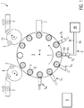
- FIG. 1 an exemplary embodiment according to the invention of a direct printing machine 1 for printing containers 2 with direct printing is shown in an overview. It can be seen that the containers 2, for example coming from a filler and a closer, are fed to the conveyor 3 with the feed star 9.
- the container receptacles 4 which are only shown schematically here, are arranged on the conveyor 3.
- the container receptacles 4 can comprise, for example, a turntable and a centering bell in order to accommodate the container base or the mouth area of the respective container 2.
- the conveyor 3 is designed, for example, as a carousel and rotates around the axis A so that the containers 2 in the container receptacles 4 are transported past the stationary direct printing stations 5 W , 5 C , 5 M , 5 Y , 5 K in the transport direction T.
- the stationary direct printing stations 5 W , 5 C , 5 M , 5 Y , 5 K are arranged around the circumference of the conveyor 3.
- the stationary direct printing stations 5 W , 5 C , 5 M , 5 Y , 5 K each comprise only one, two or more than three direct printing heads 50.
- the stationary direct printing stations 5 W , 5 C , 5 M , 5 Y , 5 K are designed for printing with printing inks of different colors, corresponding to the reference symbols 5 W , 5 C , 5 M , 5 Y , 5 K with white, cyan, magenta, Yellow and black.
- the printing inks are preferably UV-curable in order to enable a quick drying process.
- the conveyor 3 is designed for intermittent transport of the containers 2, the container receptacles 4 being stopped at printing positions opposite the stationary direct printing stations 5 W , 5 C , 5 M , 5 Y , 5 K.
- the containers 2 are rotated about their longitudinal axes by means of the container receptacles 4 and are printed by the direct print heads 50 according to the inkjet principle.
- the conveyor 3 is designed to continuously transport the containers 2, in particular when printing molded containers.
- the containers 2 with the container receptacles 4 are pivoted by an angle with respect to the direct print heads 50 in such a way that the printing distance varies in the smallest possible range.
- the direct print heads 50 each have at least one row of nozzles with a large number, for example 1000, print nozzles which are controlled by the control unit 8 in such a way that individual ink droplets are dispensed onto the container 2.
- the at least one row of nozzles is aligned essentially parallel to the container axes, so that a flat direct print is generated via the rotation by means of the container receptacles 4.
- the containers 2 are moved past the curing station 7 by means of the conveyor 3 and the printing ink is cured by means of UV light. It is also conceivable that further pinning stations are arranged between the individual stationary direct printing stations 5 W , 5 C , 5 M , 5 Y , 5 K in order to fix the individual colors.
- the containers 2 are transported by the conveyor 3 to the discharge star 10 and fed to further processing stations, for example a packaging machine.
- the direct printing machine 1 comprises the ink supply system 6 for supplying the direct printing heads 50 with printing ink from a storage tank. It goes without saying that a corresponding ink supply system is also attached to the stationary direct printing stations 5 W , 5 C , 5 M , 5 K.
- the ink supply system 6 consists of a part 6a directly attached to the direct print heads 50 and a second part 6b with the storage tank.
- the two parts 6a, 6b are connected to one another via sections of the flow 6v and the return 6r.
- the control unit 8 can also be seen, with which the direct printing machine 1, in particular the conveyor 3, the container receptacles 4, the stationary direct printing stations 5 W , 5 C , 5 M , 5 Y , 5 K , the ink supply system 6, the evaluation unit 7, the Infeed star 9 and the outlet star 10 are controlled.
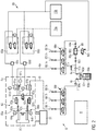
- FIG. 11 is a circulating variant of the ink supply system 6 from FIG Figure 1 shown as a diagram view.
- the ink supply system 6 is for supplying the direct print heads 50 from the Figure 1 formed with printing ink 60a from the storage tank 60.
- the distributor units 66v and 66r For the sake of clarity, only a single supply line to one of the direct print heads 50 is shown from the distributor units 66v and 66r. It goes without saying that two corresponding supply lines with the two remaining direct print heads 50 are attached to the distributor units 66v, 66r.
- the distribution units 66v and 66r can also be designed to distribute the printing ink to only two or more than three of the direct print heads 50.
- the storage tank 60 can be seen, in which there is a supply of printing ink 60a.
- the supply is constantly stirred with the agitator 60b in order to mix in printing ink 60a flowing back from the return 6r and thus to ensure a high degree of homogeneity. In addition, this generally prevents pigments from settling out of the printing ink 60a.
- the printing ink is removed from the storage tank 60 via the feed 6v and conveyed to the direct print heads 50 by means of the feed ink pump 67a.
- a pressure relief valve 67b is located parallel to the supply ink pump 67a in order to intercept pressure peaks.
- the replaceable maintenance unit 68 with the ink filter 68a and the degassing cartridge 68b which can be disconnected from the ink flow and exchanged by means of the quick-release couplings 68d, 68e, is located in the flow 6v after the supply ink pump 67a.
- the ink filter 68a removes particles and the degassing cartridge 68b removes bubbles and / or dissolved gases from the printing ink 60a.
- the degassing cartridge 68b is connected to the vacuum supply 70b via the valve 68c.
- the valve 68c is preferably only opened when the supply ink pump 67a is delivering the printing ink 60a. Thereby, the printing ink 60a is uniformly degassed.
- the printing ink is then distributed via the first distribution unit 66v to the direct print heads 50, which are each supplied with printing ink via the connections 66.1v, 66.2v and 66.3v.
- a switching valve is provided for each port 66.1v, 66.2v, 66.3v to control the flow of ink.
- the printing ink is fed with the flow 6v via the flow header tank 61a, the valve island 62 to the direct print head 50 and from there with the return 6r back via the valve island 62, the return header tank 61b to the second distributor unit 66r.
- the returning printing ink from the individual direct print heads 50 from the connections 66.1r, 66.2r or 66.3r is combined again and optionally conveyed back to the storage tank 60 via the return ink pump 71.
- a switching valve is provided for each connection 66.1r, 66.2r, 66.3r in order to control the flow of ink.
- the forward header tank 61a and the return header tank 61b serve to adjust the meniscus pressure and the circulation of the printing ink 60a through the direct print head 50.
- the first pneumatic unit 69a is assigned to the flow header tank 61a and the second pneumatic unit 69b is assigned to the return header tank 61b. They each include a pressure sensor to the To regulate pressure with two proportional valves from a compressed air supply 70a or a vacuum supply 70b so that an air cushion with the desired pressure is created in the respective header tank 61a, 61b.
- a pressure gradient is generated between the forward header tank 61a and the return header tank 61b, whereby the circulation through the direct print head 50 can be controlled.
- the meniscus print results from the mean value of the pressures in the forward and return header tanks 61a, 61b. As a result, the direct print is printed with a particularly high quality.
- the fill level sensors 61d are arranged on the flow header tank 61a and on the return header tank 61b, via which the fill levels are detected and regulated based thereon.
- the lead header tank 61a further comprises a heating unit 61c with which the printing ink is brought to the desired temperature for optimal direct printing.
- valve island 62 is arranged in the flow 6v and in the return 6r between the two header tanks 61a, 61b and the direct print head 50.
- the valve island 62 comprises a switchable flow valve 62a in the flow 6v, a switchable return valve 62b in the return 6r and a switchable bypass valve 62c in the bypass line 62d.
- a quick-release coupling 63a, 63b is arranged between the valve island 62 and the direct print head 50 in the flow 6v and in the return 6r, in order to connect the direct print head to the ink supply system 6 or to decouple it.
- valve island 62 and the quick-release couplings 63a, 63b it is possible to first interrupt the flow of ink via the direct print head 50 and to establish it in the bridging line 62d parallel to the direct print head 50. Consequently, the printing ink no longer flows via the direct print head 50 but via the bridging line 62d. At the same time, the quick-release couplings 63a, 63b can be released and the direct print head 50 exchanged for maintenance or replacement.
- bypass valve 62c is closed again and the supply valve 62a and the return valve 62b are opened again in order to establish the flow of ink via the direct print head 50.
- valve island 62 It is also possible with the valve island 62 to interrupt the flow of ink to the print head when the direct printing machine 1 is at a standstill, in order to use the time for flushing the ink supply system 6.
- valve island 62 can be used to interrupt the flow of ink via the direct print head 50 for a pressure build-up through the header tanks 61a, 61b, so that a particularly effective purge of the print nozzles in the direct print head 50 then takes place under increased pressure.
- the flow pressure sensor 64a is arranged between the valve island 62 and the direct print head 50 in the flow 6v and the return pressure sensor 64b in the return 6r.
- the pressure conditions are recorded via the direct print head 50 and thus the meniscus pressure can be recorded and set particularly precisely.
- the two pressure sensors 64a, 64b are each arranged between the quick coupling 63a, 63b and the direct print head 50, pressure losses through the quick couplings 63a, 63b cannot falsify the measurement result.
- a flow filter 65a can be arranged between the valve island 62 and the direct print head 50 in the flow 6v and a return filter 65b for the printing ink 60a in the return 6r in order to protect the print head 50 from particles in the printing ink 60a.
- These are arranged, for example, between the respective quick couplings 63a, 63b and the direct print head 50.
- the part 6a of the ink supply system 6 attached to the direct print head 50 comprises the two header tanks 61a, 61b, the valve island 62, the quick-release couplings 63a, 63b, the flow filter 65a, the return filter 65b, the flow pressure sensor 64a and the return pressure sensor 64b , and that the part 6a is designed to be movable together with the adjustment unit 51.
- the liquid level in the header tanks 61a, 61b does not change with respect to the direct print head 50, so that the printing conditions are not changed by the movement of the direct print head 50.
- the circulating variant of the ink supply 6 is particularly suitable for the use of white printing ink with higher pigmentation, which otherwise tends to settle.
- FIG. 6 is a further embodiment of the ink supply system 6 from FIG Figure 1 shown as a non-circulating variant in a diagram view. This points all previously in relation to the Figure 2 features described, but the agitator, the return ink pump, the switching valves in the second distributor unit 66r, the return header tank and the return pressure sensor on the direct print head 50 are omitted.
- the ink supply 6 can be constructed even more simply and is particularly suitable for use with colored printing inks with less pigmentation.
- the return 6r remains in FIG Figure 2 not used during regular printing. The filling of the ink supply system 6 with the printing ink 60a is only supported during commissioning. It is also conceivable that the ink supply system 6 is emptied via the return 6r.
- the direct printing machine 1 described and the ink supply system 6 are used in regular printing operations as follows:
- the containers 2 are transported past the stationary direct printing stations 5 W , 5 C , 5 M , 5 Y , 5 K with the conveyor 3, the containers 2 at the stationary direct printing stations 5 W, 5 C , 5 M , 5 Y , 5 K respectively can be printed by three direct print heads 50 with a direct print.
- the direct print heads 50 of one color are supplied with printing ink 60a from the supply tank 60 by means of the ink supply system 6, an ink flow being established from the supply tank 60 to the direct print head 50 via the feed line 6v of the ink supply system 6.
- an ink flow is established from the direct print head 50 back to the storage tank 60 via the return 6r.
- the meniscus pressure of the printing ink 60a to the direct print head 50 with the header tanks 61a, 61b arranged in the forward and optionally in the return 6v, 6r is set so that a particularly high print quality is achieved.
- the flow of ink via the direct print head 50 can be interrupted during commissioning, maintenance, standstill and when changing the print head with the valve island 62 arranged in the forward and return lines 6v, 6r between the header tanks 61a, 61b and the direct print head 50 and for this purpose are produced in the bypass line 62d parallel to the direct print head 50.
- valve island 62 it is possible to interrupt the flow of ink via the direct print head 50 by means of the valve island 62 in order to build up the pressure of the printing ink 60a with the two header tanks 61a, 61b for a subsequent purge.
Landscapes
- Engineering & Computer Science (AREA)
- Manufacturing & Machinery (AREA)
- Ink Jet (AREA)
Claims (12)
- Machine d'impression directe (1) permettant l'impression de récipients (2) au moyen d'une impression directe, avec- au moins une station d'impression directe fixe (5W, 5C 5M, 5Y, 5K) munie d'une tête d'impression directe (50) destinée à l'impression des récipients (2) au moyen de l'impression directe,- un système d'alimentation en encre (6) destiné à l'alimentation de la tête d'impression directe (50) en encre d'impression (60a) à partir d'un réservoir de stockage (60), et- avec un transporteur (3) destiné au transport des récipients (2) devant la au moins une station d'impression directe fixe (5W, 5C, 5M, 5Y, 5K),caractérisée en ce que
dans laquelle le système d'alimentation en encre (6) comprend une arrivée (6v) et un retour (6r) pour l'encre d'impression (60a) afin de générer un flux d'encre allant du réservoir de stockage (60) vers la tête d'impression directe (50) et revenant de celle-ci, et
dans laquelle le système d'alimentation en encre (6) comprend au moins un réservoir collecteur (61a, 61b) agencé au sein de l'arrivée (6v) et/ou du retour (6r) afin d'ajuster une pression de ménisque de l'encre d'impression (60a) par rapport à la tête d'impression directe (50),
un terminal de distributeurs (62) est agencé entre le au moins un réservoir collecteur (61a, 61b) et la tête d'impression directe (50) afin d'interrompre le flux d'encre passant par la tête d'impression directe (50) et, à cet effet, de le générer parallèlement à la tête d'impression directe (50) au sein d'une conduite de dérivation (62d), et
en ce que le terminal de distributeurs (62) comprend, au sein de l'arrivée (6v), une vanne d'arrivée (62a) commutable et, au sein du retour (6r), une vanne de retour (62b) commutable et, au sein de la conduite de dérivation (62d), une vanne de dérivation (62c) commutable. - Machine d'impression directe (1) selon la revendication 1, dans laquelle au moins un couplage rapide (63a, 63b) est agencé entre le terminal de distributeurs (62) et la tête d'impression directe (50) afin de connecter ou déconnecter de manière sélective la tête d'impression directe (50) par rapport au système d'alimentation en encre (6).
- Machine d'impression directe (1) selon la revendication 1 ou 2, dans laquelle un capteur de pression d'arrivée (64a) est agencé au sein de l'arrivée (6v) et éventuellement un capteur de pression de retour (64b) est agencé au sein du retour (6r), entre le terminal de distributeurs (62) et la tête d'impression directe (50), afin de mesurer la pression de ménisque.
- Machine d'impression directe (1) selon les revendications 2 et 3, dans laquelle le capteur de pression d'arrivée (64a) et éventuellement le capteur de pression de retour (64b) sont agencés entre le couplage rapide (63a, 63b) respectif et la tête d'impression directe (50).
- Machine d'impression directe (1) selon l'une quelconque des revendications précédentes, dans laquelle, entre le terminal de distributeurs (62) et la tête d'impression directe (50), un filtre d'arrivée (65a) est agencé au sein de l'arrivée (6v) et éventuellement un filtre de retour (65b) est agencé au sein du retour (6r), lesdits filtres étant destinés à l'encre d'impression (60a), afin de protéger la tête d'impression (50) des particules présentes dans l'encre d'impression (60a).
- Machine d'impression directe (1) selon les revendications 2 et 5, dans laquelle le filtre d'arrivée (65a) et éventuellement le filtre de retour (65b) sont agencés entre le couplage rapide (63a, 63b) respectif et la tête d'impression directe (50).
- Machine d'impression directe (1) selon l'une quelconque des revendications précédentes, dans laquelle la tête d'impression directe (50), le terminal de distributeurs (62) et le au moins un réservoir collecteur (61a, 61b) sont conçus de manière à pouvoir être déplacés grâce à une unité de réglage (51) commune.
- Machine d'impression directe (1) selon l'une quelconque des revendications précédentes, dans laquelle une unité de maintenance (68) interchangeable, munie d'un filtre à encre (68a) et d'une cartouche de dégazage (68b) et conçue de manière à pouvoir être échangée, en particulier au moyen de couplages rapides (68d, 68e), est agencée au sein de l'arrivée (6v) entre le réservoir de stockage (60) et le terminal de distributeurs (62).
- Machine d'impression directe (1) selon l'une quelconque des revendications précédentes, dans laquelle le au moins un réservoir collecteur (61a, 61b) est associé à une unité pneumatique (69a, 69b) afin de réguler la pression d'un coussin d'air dans le au moins un réservoir collecteur (61a, 61b), et dans laquelle l'unité pneumatique (69a, 69b) comprend de manière préférée une valve proportionnelle à commande piézoélectrique.
- Machine d'impression directe (1) selon l'une quelconque des revendications précédentes, dans laquelle le réservoir de stockage (60) comprend un agitateur (60b) afin d'éviter la sédimentation de l'encre d'impression (60a).
- Machine d'impression directe (1) selon l'une quelconque des revendications précédentes, dans laquelle la au moins une station d'impression directe fixe (5W, 5C, 5M, 5Y, 5K) comprend au moins une autre tête d'impression directe avec au moins un autre terminal de distributeurs et avec au moins un autre réservoir collecteur, et dans laquelle une unité de distribution (66w) est agencée après le réservoir de stockage afin de distribuer l'encre d'impression (60a) à la tête d'impression directe (50) et à la au moins une autre tête d'impression directe.
- Procédé d'impression directe permettant d'imprimer des récipients (2) au moyen d'une impression directe, dans lequel les récipients (2) sont transportés par un transporteur (3) devant au moins une station d'impression directe fixe (5W, 5C, 5M, 5Y, 5K), dans lequel les récipients (2) sont imprimés au moyen de l'impression directe au niveau de la au moins une station d'impression directe fixe (5W, 5C, 5M, 5Y, 5K) grâce à une tête d'impression directe (50), dans lequel la tête d'impression directe (50) est alimentée en encre d'impression (60a) à partir d'un réservoir de stockage (60) au moyen d'un système d'alimentation en encre (6), dans lequel un flux d'encre allant du réservoir de stockage (60) vers la tête d'impression directe (50) et revenant de celle-ci est généré à travers une arrivée (6v) et un retour (6r) du système d'alimentation en encre (6),
dans lequel une pression de ménisque de l'encre d'impression (60a) par rapport à la tête d'impression directe (50) est ajustée par au moins un réservoir collecteur (61a, 61b) agencé au sein de l'arrivée (6v) et/ou du retour (6r),
caractérisé en ce que
le flux d'encre est interrompu par un terminal de distributeurs (62) agencé au sein de l'arrivée (6v) et/ou du retour (6r) entre le au moins un réservoir collecteur (61a, 61b) et la tête d'impression directe (50) et, à cet effet, est généré parallèlement à la tête d'impression directe (50) au sein d'une conduite de dérivation (62d), et
en ce que le terminal de distributeurs (62) comprend, au sein de l'arrivée (6v), une vanne d'arrivée (62a) commutable et, au sein du retour (6r), une vanne de retour (62b) commutable et, au sein de la conduite de dérivation (62d), une vanne de dérivation (62c) commutable, dans lequel une pression dynamique est constituée au sein de l'arrivée (6v) et au sein du retour (6r) en vue d'une purge, et dans lequel l'arrivée (6v) et le retour (6r) de la tête d'impression directe (50) sont ensuite à nouveau ouvertes et la conduite de dérivation (62d) est fermée, au moyen du terminal de distributeurs (62), de sorte que la pression dynamique constituée entraine une éjection accrue de l'encre d'impression à travers la tête d'impression directe (50).
Applications Claiming Priority (1)
| Application Number | Priority Date | Filing Date | Title |
|---|---|---|---|
| DE102017215475.6A DE102017215475A1 (de) | 2017-09-04 | 2017-09-04 | Direktdruckmaschine und -verfahren zur Bedruckung von Behältern mit einem Direktdruck |
Publications (2)
| Publication Number | Publication Date |
|---|---|
| EP3450179A1 EP3450179A1 (fr) | 2019-03-06 |
| EP3450179B1 true EP3450179B1 (fr) | 2020-09-30 |
Family
ID=62874754
Family Applications (1)
| Application Number | Title | Priority Date | Filing Date |
|---|---|---|---|
| EP18182166.1A Active EP3450179B1 (fr) | 2017-09-04 | 2018-07-06 | Machine et procédé d'impression directe destinés à l'impression de récipients par impression directe |
Country Status (4)
| Country | Link |
|---|---|
| US (1) | US20190070861A1 (fr) |
| EP (1) | EP3450179B1 (fr) |
| CN (1) | CN209351083U (fr) |
| DE (1) | DE102017215475A1 (fr) |
Cited By (1)
| Publication number | Priority date | Publication date | Assignee | Title |
|---|---|---|---|---|
| DE102022122252A1 (de) | 2022-09-02 | 2024-03-07 | Dekron Gmbh | Tintenversorgungssystem und Tintenversorgungsverfahren für den Digitaldruck |
Families Citing this family (2)
| Publication number | Priority date | Publication date | Assignee | Title |
|---|---|---|---|---|
| US11969994B2 (en) * | 2020-09-14 | 2024-04-30 | Assa Abloy Ab | Ink jet nozzle health and printing reliability |
| JP2024042364A (ja) * | 2022-09-15 | 2024-03-28 | 株式会社Screenホールディングス | ヘッド交換方法、インクジェット印刷装置、およびヘッド交換支援プログラム |
Family Cites Families (19)
| Publication number | Priority date | Publication date | Assignee | Title |
|---|---|---|---|---|
| US6095572A (en) * | 1998-01-20 | 2000-08-01 | Optimize Technologies, Inc. | Quarter turn quick connect fitting |
| US7803221B2 (en) * | 2003-08-25 | 2010-09-28 | DIP Tech LTd.. | Ink for ceramic surfaces |
| US7350890B2 (en) * | 2004-08-26 | 2008-04-01 | The Boeing Company | Apparatus and methods for applying images to a surface |
| AT507445B1 (de) * | 2008-10-31 | 2011-09-15 | Durst Phototechnik Digital Technology Gmbh | Tintenversorgungssystem für einen tintenstrahldrucker |
| DE102009020702B4 (de) | 2009-05-11 | 2011-09-15 | Khs Gmbh | Drucksystem zum Bedrucken von Flaschen oder dergleichen Behältern sowie Druckvorrichtung oder -maschine mit einem solchen Drucksystem |
| DE102009033810A1 (de) * | 2009-07-18 | 2011-01-27 | Till, Volker, Dipl.-Ing. | Anlage zum Bedrucken von Behältern |
| JP5773584B2 (ja) * | 2010-06-18 | 2015-09-02 | キヤノン株式会社 | プリント装置及びそのインク供給方法 |
| DE102011122910B4 (de) * | 2011-09-02 | 2015-12-31 | Khs Gmbh | Vorrichtung zum Behandeln von Packmitteln unter Druckbeaufschlagung und Halte- und Zentriereinheit dazu |
| JP5921136B2 (ja) * | 2011-10-21 | 2016-05-24 | キヤノン株式会社 | インクジェット記録装置および物流インクの排出方法 |
| DE102013217679A1 (de) | 2013-09-04 | 2015-03-05 | Heidelberger Druckmaschinen Ag | Druckmaschine für den Tintenstrahldruck auf Behälter |
| DE102013110108A1 (de) * | 2013-09-13 | 2015-03-19 | Khs Gmbh | Drucksystem zum Bedrucken von Flaschen oder dergleichen Behältern sowie Druckvorrichtung oder –maschine mit einem solchen Drucksystem |
| DE102013110771A1 (de) * | 2013-09-30 | 2015-04-02 | Océ Printing Systems GmbH & Co. KG | Anordnung zur Versorgung einer mindestens einen Druckkopf aufweisenden Druckkopfeinheit mit Tinte bei einem Tintendruckgerät |
| US9168752B2 (en) * | 2013-10-18 | 2015-10-27 | Hewlett-Packard Development Company, L.P. | Print head priming systems |
| DE102014110520A1 (de) * | 2014-07-25 | 2016-01-28 | Krones Ag | Direktdruckmaschine mit Tintenversorgungssystem |
| DE102015215224A1 (de) * | 2015-08-10 | 2017-02-16 | Krones Ag | Behälterbehandlungsmaschine und Verfahren zur Bedruckung von Behältern |
| DE102016106011A1 (de) * | 2016-04-01 | 2017-10-05 | Till Gmbh | Vorrichtung und Verfahren zur Tintenversorgung beim Digitaldruck |
| JP6870229B2 (ja) * | 2016-07-22 | 2021-05-12 | ブラザー工業株式会社 | ヘッドモジュール、液体吐出装置、及び、ケース |
| DE102016217881A1 (de) * | 2016-09-19 | 2018-03-22 | Kba-Metronic Gmbh | Druckaggregat |
| US10112412B2 (en) * | 2017-04-03 | 2018-10-30 | Xerox Corporation | Object holder for a direct-to-object printer |
-
2017
- 2017-09-04 DE DE102017215475.6A patent/DE102017215475A1/de active Pending
-
2018
- 2018-07-06 EP EP18182166.1A patent/EP3450179B1/fr active Active
- 2018-09-03 CN CN201821433682.5U patent/CN209351083U/zh active Active
- 2018-09-04 US US16/120,976 patent/US20190070861A1/en not_active Abandoned
Non-Patent Citations (1)
| Title |
|---|
| None * |
Cited By (1)
| Publication number | Priority date | Publication date | Assignee | Title |
|---|---|---|---|---|
| DE102022122252A1 (de) | 2022-09-02 | 2024-03-07 | Dekron Gmbh | Tintenversorgungssystem und Tintenversorgungsverfahren für den Digitaldruck |
Also Published As
| Publication number | Publication date |
|---|---|
| US20190070861A1 (en) | 2019-03-07 |
| EP3450179A1 (fr) | 2019-03-06 |
| CN209351083U (zh) | 2019-09-06 |
| DE102017215475A1 (de) | 2019-03-07 |
Similar Documents
| Publication | Publication Date | Title |
|---|---|---|
| EP2429822B1 (fr) | Systeme d'impression pour realiser des impressions sur des bouteilles ou recipients analogues et dispositif ou machine d'impression dote d'un tel systeme | |
| EP3450179B1 (fr) | Machine et procédé d'impression directe destinés à l'impression de récipients par impression directe | |
| EP2153998B1 (fr) | Système d'alimentation en encre et procédé de nettoyage d'un tel système d'alimentation en encre | |
| DE102006013800B3 (de) | Transportsystem für Flaschen oder dergleichen Behälter sowie Anlage zum Behandeln von Flaschen oder dergleichen Behälter | |
| AT507445B1 (de) | Tintenversorgungssystem für einen tintenstrahldrucker | |
| EP2019809B1 (fr) | Procédé et dispositif de moussage commandé d'un produit mis en bouteilles ou dans des contenants similaires | |
| EP2512812B1 (fr) | Installation destinée à l'impression de récipients | |
| EP2292550A1 (fr) | Dispositif et procédé de fabrication de bouteilles en plastique | |
| DE102015215227A1 (de) | Behälterbehandlungsmaschine und Verfahren zur Bedruckung von Behältern | |
| EP3044001B1 (fr) | Système et dispositif d'impression de bouteilles ou de récipients comportant un réservoir d'alimentation en plusieurs parties et procédé | |
| EP2977212B1 (fr) | Machine d'impression directe dotée de système d'alimentation en encre | |
| DE102007061277A1 (de) | Etikettiermaschine | |
| EP3887265A1 (fr) | Procédé de pulvérisation d'une colle à froid sur des étiquettes et groupe d'étiquetage pour des contenants | |
| EP3838833A1 (fr) | Dispositif de remplissage d'un récipient d'un produit de remplissage | |
| EP3834954A1 (fr) | Appareil de remplissage de contenant avec nettoyage cip | |
| EP3558685B1 (fr) | Procédé et machine d'impression directe pour imprimer sur des récipients en différents types de matériau en impression directement | |
| EP3450183B1 (fr) | Machine et procédé d'impression directe destinés à l'impression de récipients par impression directe | |
| DE102021107727A1 (de) | Abfüllanlage und Verfahren zur aseptischen Abfüllung flüssiger Produkte in Flaschen | |
| WO2019042647A1 (fr) | Machine et procédé de traitement pour contenants | |
| EP3365176B1 (fr) | Procédé d'impression directe et machine de traitement de récipient permettant l'impression d'une pluralité de récipients de structure similaire | |
| EP3684620B1 (fr) | Machine et procédé d'impression directe pour effectuer une impression directe multicolore sur des contenants | |
| EP4304868A1 (fr) | Procédé de changement d'au moins un fluide d'impression et procédé de nettoyage et/ou d'entretien d'au moins un système d'alimentation en fluide d'impression, et machine d'impression |
Legal Events
| Date | Code | Title | Description |
|---|---|---|---|
| PUAI | Public reference made under article 153(3) epc to a published international application that has entered the european phase |
Free format text: ORIGINAL CODE: 0009012 |
|
| STAA | Information on the status of an ep patent application or granted ep patent |
Free format text: STATUS: THE APPLICATION HAS BEEN PUBLISHED |
|
| AK | Designated contracting states |
Kind code of ref document: A1 Designated state(s): AL AT BE BG CH CY CZ DE DK EE ES FI FR GB GR HR HU IE IS IT LI LT LU LV MC MK MT NL NO PL PT RO RS SE SI SK SM TR |
|
| AX | Request for extension of the european patent |
Extension state: BA ME |
|
| STAA | Information on the status of an ep patent application or granted ep patent |
Free format text: STATUS: REQUEST FOR EXAMINATION WAS MADE |
|
| 17P | Request for examination filed |
Effective date: 20190830 |
|
| RBV | Designated contracting states (corrected) |
Designated state(s): AL AT BE BG CH CY CZ DE DK EE ES FI FR GB GR HR HU IE IS IT LI LT LU LV MC MK MT NL NO PL PT RO RS SE SI SK SM TR |
|
| GRAP | Despatch of communication of intention to grant a patent |
Free format text: ORIGINAL CODE: EPIDOSNIGR1 |
|
| STAA | Information on the status of an ep patent application or granted ep patent |
Free format text: STATUS: GRANT OF PATENT IS INTENDED |
|
| INTG | Intention to grant announced |
Effective date: 20200428 |
|
| GRAS | Grant fee paid |
Free format text: ORIGINAL CODE: EPIDOSNIGR3 |
|
| GRAA | (expected) grant |
Free format text: ORIGINAL CODE: 0009210 |
|
| STAA | Information on the status of an ep patent application or granted ep patent |
Free format text: STATUS: THE PATENT HAS BEEN GRANTED |
|
| AK | Designated contracting states |
Kind code of ref document: B1 Designated state(s): AL AT BE BG CH CY CZ DE DK EE ES FI FR GB GR HR HU IE IS IT LI LT LU LV MC MK MT NL NO PL PT RO RS SE SI SK SM TR |
|
| REG | Reference to a national code |
Ref country code: CH Ref legal event code: EP Ref country code: GB Ref legal event code: FG4D Free format text: NOT ENGLISH |
|
| REG | Reference to a national code |
Ref country code: AT Ref legal event code: REF Ref document number: 1318404 Country of ref document: AT Kind code of ref document: T Effective date: 20201015 |
|
| REG | Reference to a national code |
Ref country code: DE Ref legal event code: R096 Ref document number: 502018002591 Country of ref document: DE |
|
| REG | Reference to a national code |
Ref country code: IE Ref legal event code: FG4D Free format text: LANGUAGE OF EP DOCUMENT: GERMAN |
|
| PG25 | Lapsed in a contracting state [announced via postgrant information from national office to epo] |
Ref country code: FI Free format text: LAPSE BECAUSE OF FAILURE TO SUBMIT A TRANSLATION OF THE DESCRIPTION OR TO PAY THE FEE WITHIN THE PRESCRIBED TIME-LIMIT Effective date: 20200930 Ref country code: SE Free format text: LAPSE BECAUSE OF FAILURE TO SUBMIT A TRANSLATION OF THE DESCRIPTION OR TO PAY THE FEE WITHIN THE PRESCRIBED TIME-LIMIT Effective date: 20200930 Ref country code: HR Free format text: LAPSE BECAUSE OF FAILURE TO SUBMIT A TRANSLATION OF THE DESCRIPTION OR TO PAY THE FEE WITHIN THE PRESCRIBED TIME-LIMIT Effective date: 20200930 Ref country code: GR Free format text: LAPSE BECAUSE OF FAILURE TO SUBMIT A TRANSLATION OF THE DESCRIPTION OR TO PAY THE FEE WITHIN THE PRESCRIBED TIME-LIMIT Effective date: 20201231 Ref country code: BG Free format text: LAPSE BECAUSE OF FAILURE TO SUBMIT A TRANSLATION OF THE DESCRIPTION OR TO PAY THE FEE WITHIN THE PRESCRIBED TIME-LIMIT Effective date: 20201230 Ref country code: NO Free format text: LAPSE BECAUSE OF FAILURE TO SUBMIT A TRANSLATION OF THE DESCRIPTION OR TO PAY THE FEE WITHIN THE PRESCRIBED TIME-LIMIT Effective date: 20201230 |
|
| PG25 | Lapsed in a contracting state [announced via postgrant information from national office to epo] |
Ref country code: RS Free format text: LAPSE BECAUSE OF FAILURE TO SUBMIT A TRANSLATION OF THE DESCRIPTION OR TO PAY THE FEE WITHIN THE PRESCRIBED TIME-LIMIT Effective date: 20200930 Ref country code: LV Free format text: LAPSE BECAUSE OF FAILURE TO SUBMIT A TRANSLATION OF THE DESCRIPTION OR TO PAY THE FEE WITHIN THE PRESCRIBED TIME-LIMIT Effective date: 20200930 |
|
| REG | Reference to a national code |
Ref country code: NL Ref legal event code: MP Effective date: 20200930 |
|
| REG | Reference to a national code |
Ref country code: LT Ref legal event code: MG4D |
|
| PG25 | Lapsed in a contracting state [announced via postgrant information from national office to epo] |
Ref country code: EE Free format text: LAPSE BECAUSE OF FAILURE TO SUBMIT A TRANSLATION OF THE DESCRIPTION OR TO PAY THE FEE WITHIN THE PRESCRIBED TIME-LIMIT Effective date: 20200930 Ref country code: RO Free format text: LAPSE BECAUSE OF FAILURE TO SUBMIT A TRANSLATION OF THE DESCRIPTION OR TO PAY THE FEE WITHIN THE PRESCRIBED TIME-LIMIT Effective date: 20200930 Ref country code: PT Free format text: LAPSE BECAUSE OF FAILURE TO SUBMIT A TRANSLATION OF THE DESCRIPTION OR TO PAY THE FEE WITHIN THE PRESCRIBED TIME-LIMIT Effective date: 20210201 Ref country code: CZ Free format text: LAPSE BECAUSE OF FAILURE TO SUBMIT A TRANSLATION OF THE DESCRIPTION OR TO PAY THE FEE WITHIN THE PRESCRIBED TIME-LIMIT Effective date: 20200930 Ref country code: LT Free format text: LAPSE BECAUSE OF FAILURE TO SUBMIT A TRANSLATION OF THE DESCRIPTION OR TO PAY THE FEE WITHIN THE PRESCRIBED TIME-LIMIT Effective date: 20200930 Ref country code: SM Free format text: LAPSE BECAUSE OF FAILURE TO SUBMIT A TRANSLATION OF THE DESCRIPTION OR TO PAY THE FEE WITHIN THE PRESCRIBED TIME-LIMIT Effective date: 20200930 |
|
| PG25 | Lapsed in a contracting state [announced via postgrant information from national office to epo] |
Ref country code: PL Free format text: LAPSE BECAUSE OF FAILURE TO SUBMIT A TRANSLATION OF THE DESCRIPTION OR TO PAY THE FEE WITHIN THE PRESCRIBED TIME-LIMIT Effective date: 20200930 Ref country code: IS Free format text: LAPSE BECAUSE OF FAILURE TO SUBMIT A TRANSLATION OF THE DESCRIPTION OR TO PAY THE FEE WITHIN THE PRESCRIBED TIME-LIMIT Effective date: 20210130 Ref country code: AL Free format text: LAPSE BECAUSE OF FAILURE TO SUBMIT A TRANSLATION OF THE DESCRIPTION OR TO PAY THE FEE WITHIN THE PRESCRIBED TIME-LIMIT Effective date: 20200930 Ref country code: ES Free format text: LAPSE BECAUSE OF FAILURE TO SUBMIT A TRANSLATION OF THE DESCRIPTION OR TO PAY THE FEE WITHIN THE PRESCRIBED TIME-LIMIT Effective date: 20200930 |
|
| PG25 | Lapsed in a contracting state [announced via postgrant information from national office to epo] |
Ref country code: NL Free format text: LAPSE BECAUSE OF FAILURE TO SUBMIT A TRANSLATION OF THE DESCRIPTION OR TO PAY THE FEE WITHIN THE PRESCRIBED TIME-LIMIT Effective date: 20200930 Ref country code: SK Free format text: LAPSE BECAUSE OF FAILURE TO SUBMIT A TRANSLATION OF THE DESCRIPTION OR TO PAY THE FEE WITHIN THE PRESCRIBED TIME-LIMIT Effective date: 20200930 |
|
| REG | Reference to a national code |
Ref country code: DE Ref legal event code: R097 Ref document number: 502018002591 Country of ref document: DE |
|
| PLBE | No opposition filed within time limit |
Free format text: ORIGINAL CODE: 0009261 |
|
| STAA | Information on the status of an ep patent application or granted ep patent |
Free format text: STATUS: NO OPPOSITION FILED WITHIN TIME LIMIT |
|
| PG25 | Lapsed in a contracting state [announced via postgrant information from national office to epo] |
Ref country code: DK Free format text: LAPSE BECAUSE OF FAILURE TO SUBMIT A TRANSLATION OF THE DESCRIPTION OR TO PAY THE FEE WITHIN THE PRESCRIBED TIME-LIMIT Effective date: 20200930 |
|
| 26N | No opposition filed |
Effective date: 20210701 |
|
| PG25 | Lapsed in a contracting state [announced via postgrant information from national office to epo] |
Ref country code: SI Free format text: LAPSE BECAUSE OF FAILURE TO SUBMIT A TRANSLATION OF THE DESCRIPTION OR TO PAY THE FEE WITHIN THE PRESCRIBED TIME-LIMIT Effective date: 20200930 |
|
| REG | Reference to a national code |
Ref country code: CH Ref legal event code: PL |
|
| PG25 | Lapsed in a contracting state [announced via postgrant information from national office to epo] |
Ref country code: MC Free format text: LAPSE BECAUSE OF FAILURE TO SUBMIT A TRANSLATION OF THE DESCRIPTION OR TO PAY THE FEE WITHIN THE PRESCRIBED TIME-LIMIT Effective date: 20200930 |
|
| REG | Reference to a national code |
Ref country code: BE Ref legal event code: MM Effective date: 20210731 |
|
| PG25 | Lapsed in a contracting state [announced via postgrant information from national office to epo] |
Ref country code: LI Free format text: LAPSE BECAUSE OF NON-PAYMENT OF DUE FEES Effective date: 20210731 Ref country code: CH Free format text: LAPSE BECAUSE OF NON-PAYMENT OF DUE FEES Effective date: 20210731 |
|
| PG25 | Lapsed in a contracting state [announced via postgrant information from national office to epo] |
Ref country code: IS Free format text: LAPSE BECAUSE OF FAILURE TO SUBMIT A TRANSLATION OF THE DESCRIPTION OR TO PAY THE FEE WITHIN THE PRESCRIBED TIME-LIMIT Effective date: 20210130 Ref country code: LU Free format text: LAPSE BECAUSE OF NON-PAYMENT OF DUE FEES Effective date: 20210706 |
|
| PG25 | Lapsed in a contracting state [announced via postgrant information from national office to epo] |
Ref country code: IE Free format text: LAPSE BECAUSE OF NON-PAYMENT OF DUE FEES Effective date: 20210706 Ref country code: BE Free format text: LAPSE BECAUSE OF NON-PAYMENT OF DUE FEES Effective date: 20210731 |
|
| GBPC | Gb: european patent ceased through non-payment of renewal fee |
Effective date: 20220706 |
|
| PG25 | Lapsed in a contracting state [announced via postgrant information from national office to epo] |
Ref country code: GB Free format text: LAPSE BECAUSE OF NON-PAYMENT OF DUE FEES Effective date: 20220706 |
|
| PG25 | Lapsed in a contracting state [announced via postgrant information from national office to epo] |
Ref country code: CY Free format text: LAPSE BECAUSE OF FAILURE TO SUBMIT A TRANSLATION OF THE DESCRIPTION OR TO PAY THE FEE WITHIN THE PRESCRIBED TIME-LIMIT Effective date: 20200930 |
|
| PG25 | Lapsed in a contracting state [announced via postgrant information from national office to epo] |
Ref country code: HU Free format text: LAPSE BECAUSE OF FAILURE TO SUBMIT A TRANSLATION OF THE DESCRIPTION OR TO PAY THE FEE WITHIN THE PRESCRIBED TIME-LIMIT; INVALID AB INITIO Effective date: 20180706 |
|
| PGFP | Annual fee paid to national office [announced via postgrant information from national office to epo] |
Ref country code: IT Payment date: 20230612 Year of fee payment: 6 Ref country code: FR Payment date: 20230620 Year of fee payment: 6 |
|
| PGFP | Annual fee paid to national office [announced via postgrant information from national office to epo] |
Ref country code: DE Payment date: 20230531 Year of fee payment: 6 |
|
| PG25 | Lapsed in a contracting state [announced via postgrant information from national office to epo] |
Ref country code: MK Free format text: LAPSE BECAUSE OF FAILURE TO SUBMIT A TRANSLATION OF THE DESCRIPTION OR TO PAY THE FEE WITHIN THE PRESCRIBED TIME-LIMIT Effective date: 20200930 |