EP3450104B1 - Method and apparatus for fluid cavitation abrasive surface finishing - Google Patents
Method and apparatus for fluid cavitation abrasive surface finishing Download PDFInfo
- Publication number
- EP3450104B1 EP3450104B1 EP18190086.1A EP18190086A EP3450104B1 EP 3450104 B1 EP3450104 B1 EP 3450104B1 EP 18190086 A EP18190086 A EP 18190086A EP 3450104 B1 EP3450104 B1 EP 3450104B1
- Authority
- EP
- European Patent Office
- Prior art keywords
- abrasive media
- liquid
- cavitation bubbles
- cavitation
- workpiece
- Prior art date
- Legal status (The legal status is an assumption and is not a legal conclusion. Google has not performed a legal analysis and makes no representation as to the accuracy of the status listed.)
- Active
Links
- 238000000034 method Methods 0.000 title claims description 32
- 239000012530 fluid Substances 0.000 title description 16
- 239000007788 liquid Substances 0.000 claims description 36
- XLYOFNOQVPJJNP-UHFFFAOYSA-N water Substances O XLYOFNOQVPJJNP-UHFFFAOYSA-N 0.000 claims description 32
- 239000000463 material Substances 0.000 claims description 17
- 239000002245 particle Substances 0.000 claims description 12
- VYPSYNLAJGMNEJ-UHFFFAOYSA-N Silicium dioxide Chemical compound O=[Si]=O VYPSYNLAJGMNEJ-UHFFFAOYSA-N 0.000 claims description 8
- 230000033001 locomotion Effects 0.000 claims description 8
- 239000003082 abrasive agent Substances 0.000 claims description 7
- 238000007599 discharging Methods 0.000 claims description 6
- 239000011521 glass Substances 0.000 claims description 4
- 229910052751 metal Inorganic materials 0.000 claims description 4
- 239000002184 metal Substances 0.000 claims description 4
- 239000008262 pumice Substances 0.000 claims description 4
- 239000000377 silicon dioxide Substances 0.000 claims description 4
- 235000005824 Zea mays ssp. parviglumis Nutrition 0.000 claims description 3
- 235000002017 Zea mays subsp mays Nutrition 0.000 claims description 3
- 239000000919 ceramic Substances 0.000 claims description 3
- 235000005822 corn Nutrition 0.000 claims description 3
- 230000003993 interaction Effects 0.000 claims description 3
- TWNQGVIAIRXVLR-UHFFFAOYSA-N oxo(oxoalumanyloxy)alumane Chemical compound O=[Al]O[Al]=O TWNQGVIAIRXVLR-UHFFFAOYSA-N 0.000 claims description 3
- 238000005086 pumping Methods 0.000 claims description 2
- 230000005465 channeling Effects 0.000 claims 3
- 240000008042 Zea mays Species 0.000 claims 1
- 238000004519 manufacturing process Methods 0.000 description 10
- 239000000654 additive Substances 0.000 description 7
- 230000000996 additive effect Effects 0.000 description 7
- 239000000203 mixture Substances 0.000 description 7
- 230000006835 compression Effects 0.000 description 6
- 238000007906 compression Methods 0.000 description 6
- 230000003746 surface roughness Effects 0.000 description 6
- 238000010586 diagram Methods 0.000 description 5
- 230000008569 process Effects 0.000 description 5
- 238000004140 cleaning Methods 0.000 description 4
- 238000003754 machining Methods 0.000 description 4
- 230000007246 mechanism Effects 0.000 description 3
- 230000001105 regulatory effect Effects 0.000 description 3
- 239000000126 substance Substances 0.000 description 3
- 230000007704 transition Effects 0.000 description 3
- 241000209149 Zea Species 0.000 description 2
- 230000007423 decrease Effects 0.000 description 2
- 238000007730 finishing process Methods 0.000 description 2
- 238000002844 melting Methods 0.000 description 2
- 230000008018 melting Effects 0.000 description 2
- 239000000843 powder Substances 0.000 description 2
- 230000000135 prohibitive effect Effects 0.000 description 2
- 239000002994 raw material Substances 0.000 description 2
- 238000005480 shot peening Methods 0.000 description 2
- 125000006850 spacer group Chemical group 0.000 description 2
- 241000238586 Cirripedia Species 0.000 description 1
- RTAQQCXQSZGOHL-UHFFFAOYSA-N Titanium Chemical compound [Ti] RTAQQCXQSZGOHL-UHFFFAOYSA-N 0.000 description 1
- 230000001154 acute effect Effects 0.000 description 1
- 238000005422 blasting Methods 0.000 description 1
- 230000008859 change Effects 0.000 description 1
- 230000003247 decreasing effect Effects 0.000 description 1
- 230000001419 dependent effect Effects 0.000 description 1
- 230000008021 deposition Effects 0.000 description 1
- 230000000694 effects Effects 0.000 description 1
- 238000010894 electron beam technology Methods 0.000 description 1
- 238000005516 engineering process Methods 0.000 description 1
- 239000006260 foam Substances 0.000 description 1
- 230000003116 impacting effect Effects 0.000 description 1
- 230000006872 improvement Effects 0.000 description 1
- 238000003801 milling Methods 0.000 description 1
- 238000010422 painting Methods 0.000 description 1
- 230000008439 repair process Effects 0.000 description 1
- 239000011369 resultant mixture Substances 0.000 description 1
- 239000000725 suspension Substances 0.000 description 1
- 239000010936 titanium Substances 0.000 description 1
- 229910052719 titanium Inorganic materials 0.000 description 1
- 230000001960 triggered effect Effects 0.000 description 1
Images

Classifications
-
- B—PERFORMING OPERATIONS; TRANSPORTING
- B24—GRINDING; POLISHING
- B24C—ABRASIVE OR RELATED BLASTING WITH PARTICULATE MATERIAL
- B24C1/00—Methods for use of abrasive blasting for producing particular effects; Use of auxiliary equipment in connection with such methods
- B24C1/10—Methods for use of abrasive blasting for producing particular effects; Use of auxiliary equipment in connection with such methods for compacting surfaces, e.g. shot-peening
-
- B—PERFORMING OPERATIONS; TRANSPORTING
- B24—GRINDING; POLISHING
- B24C—ABRASIVE OR RELATED BLASTING WITH PARTICULATE MATERIAL
- B24C1/00—Methods for use of abrasive blasting for producing particular effects; Use of auxiliary equipment in connection with such methods
- B24C1/08—Methods for use of abrasive blasting for producing particular effects; Use of auxiliary equipment in connection with such methods for polishing surfaces, e.g. smoothing a surface by making use of liquid-borne abrasives
-
- B—PERFORMING OPERATIONS; TRANSPORTING
- B05—SPRAYING OR ATOMISING IN GENERAL; APPLYING FLUENT MATERIALS TO SURFACES, IN GENERAL
- B05B—SPRAYING APPARATUS; ATOMISING APPARATUS; NOZZLES
- B05B12/00—Arrangements for controlling delivery; Arrangements for controlling the spray area
- B05B12/14—Arrangements for controlling delivery; Arrangements for controlling the spray area for supplying a selected one of a plurality of liquids or other fluent materials or several in selected proportions to a spray apparatus, e.g. to a single spray outlet
-
- B—PERFORMING OPERATIONS; TRANSPORTING
- B05—SPRAYING OR ATOMISING IN GENERAL; APPLYING FLUENT MATERIALS TO SURFACES, IN GENERAL
- B05B—SPRAYING APPARATUS; ATOMISING APPARATUS; NOZZLES
- B05B7/00—Spraying apparatus for discharge of liquids or other fluent materials from two or more sources, e.g. of liquid and air, of powder and gas
- B05B7/02—Spray pistols; Apparatus for discharge
- B05B7/10—Spray pistols; Apparatus for discharge producing a swirling discharge
-
- B—PERFORMING OPERATIONS; TRANSPORTING
- B05—SPRAYING OR ATOMISING IN GENERAL; APPLYING FLUENT MATERIALS TO SURFACES, IN GENERAL
- B05B—SPRAYING APPARATUS; ATOMISING APPARATUS; NOZZLES
- B05B7/00—Spraying apparatus for discharge of liquids or other fluent materials from two or more sources, e.g. of liquid and air, of powder and gas
- B05B7/14—Spraying apparatus for discharge of liquids or other fluent materials from two or more sources, e.g. of liquid and air, of powder and gas designed for spraying particulate materials
- B05B7/1404—Arrangements for supplying particulate material
- B05B7/1463—Arrangements for supplying particulate material the means for supplying particulate material comprising a gas inlet for pressurising or avoiding depressurisation of a powder container
-
- B—PERFORMING OPERATIONS; TRANSPORTING
- B05—SPRAYING OR ATOMISING IN GENERAL; APPLYING FLUENT MATERIALS TO SURFACES, IN GENERAL
- B05B—SPRAYING APPARATUS; ATOMISING APPARATUS; NOZZLES
- B05B7/00—Spraying apparatus for discharge of liquids or other fluent materials from two or more sources, e.g. of liquid and air, of powder and gas
- B05B7/14—Spraying apparatus for discharge of liquids or other fluent materials from two or more sources, e.g. of liquid and air, of powder and gas designed for spraying particulate materials
- B05B7/1481—Spray pistols or apparatus for discharging particulate material
- B05B7/149—Spray pistols or apparatus for discharging particulate material with separate inlets for a particulate material and a liquid to be sprayed
-
- B—PERFORMING OPERATIONS; TRANSPORTING
- B08—CLEANING
- B08B—CLEANING IN GENERAL; PREVENTION OF FOULING IN GENERAL
- B08B3/00—Cleaning by methods involving the use or presence of liquid or steam
- B08B3/02—Cleaning by the force of jets or sprays
- B08B3/026—Cleaning by making use of hand-held spray guns; Fluid preparations therefor
- B08B3/028—Spray guns
-
- B—PERFORMING OPERATIONS; TRANSPORTING
- B24—GRINDING; POLISHING
- B24C—ABRASIVE OR RELATED BLASTING WITH PARTICULATE MATERIAL
- B24C1/00—Methods for use of abrasive blasting for producing particular effects; Use of auxiliary equipment in connection with such methods
- B24C1/06—Methods for use of abrasive blasting for producing particular effects; Use of auxiliary equipment in connection with such methods for producing matt surfaces, e.g. on plastic materials, on glass
-
- B—PERFORMING OPERATIONS; TRANSPORTING
- B24—GRINDING; POLISHING
- B24C—ABRASIVE OR RELATED BLASTING WITH PARTICULATE MATERIAL
- B24C7/00—Equipment for feeding abrasive material; Controlling the flowability, constitution, or other physical characteristics of abrasive blasts
- B24C7/0007—Equipment for feeding abrasive material; Controlling the flowability, constitution, or other physical characteristics of abrasive blasts the abrasive material being fed in a liquid carrier
-
- B—PERFORMING OPERATIONS; TRANSPORTING
- B24—GRINDING; POLISHING
- B24C—ABRASIVE OR RELATED BLASTING WITH PARTICULATE MATERIAL
- B24C7/00—Equipment for feeding abrasive material; Controlling the flowability, constitution, or other physical characteristics of abrasive blasts
- B24C7/0092—Equipment for feeding abrasive material; Controlling the flowability, constitution, or other physical characteristics of abrasive blasts the abrasive material being fed by mechanical means, e.g. by screw conveyors
-
- B—PERFORMING OPERATIONS; TRANSPORTING
- B33—ADDITIVE MANUFACTURING TECHNOLOGY
- B33Y—ADDITIVE MANUFACTURING, i.e. MANUFACTURING OF THREE-DIMENSIONAL [3-D] OBJECTS BY ADDITIVE DEPOSITION, ADDITIVE AGGLOMERATION OR ADDITIVE LAYERING, e.g. BY 3-D PRINTING, STEREOLITHOGRAPHY OR SELECTIVE LASER SINTERING
- B33Y40/00—Auxiliary operations or equipment, e.g. for material handling
- B33Y40/20—Post-treatment, e.g. curing, coating or polishing
-
- Y—GENERAL TAGGING OF NEW TECHNOLOGICAL DEVELOPMENTS; GENERAL TAGGING OF CROSS-SECTIONAL TECHNOLOGIES SPANNING OVER SEVERAL SECTIONS OF THE IPC; TECHNICAL SUBJECTS COVERED BY FORMER USPC CROSS-REFERENCE ART COLLECTIONS [XRACs] AND DIGESTS
- Y02—TECHNOLOGIES OR APPLICATIONS FOR MITIGATION OR ADAPTATION AGAINST CLIMATE CHANGE
- Y02P—CLIMATE CHANGE MITIGATION TECHNOLOGIES IN THE PRODUCTION OR PROCESSING OF GOODS
- Y02P10/00—Technologies related to metal processing
- Y02P10/25—Process efficiency
Definitions
- This disclosure relates to surface finishing. More specifically, the disclosed examples relate to systems and methods for subtractive material finishing, cleaning, and peening with a cavitated fluid.
- Additive manufacturing methods such as directed energy deposition and powder bed melting have enabled efficient manufacturing of new components with complex shapes and features which are not practical or feasible to manufacture by previous methods.
- the resulting surface finish on products made by additive manufacturing is rougher than parts produced by traditional manufacturing methods.
- Electron beam powder bed melting can create a surface roughness average (Ra) over 1,000 ⁇ M, which is more than 10 times the smooth finish required for typical structural airplane components. Machining is cost-prohibitive or not possible for complex additive manufactured components, and surface finishing methods such as grit blasting, chemical milling, and shot peening do not sufficiently improve the surface roughness.
- Cavitation peening is a promising new method of mechanically treating a surface. Cavitation bubbles are formed in a fluid by a transition to gas phase resulting from an increase in flow velocity, then collapse as the flow velocity decreases. When a cavitation bubble collapses, a micro-jet is produced that can have a speed of 1,500 m/s in some examples. As disclosed in Soyama US6855208 B1 , injecting a high speed water jet, or cavitating jet into water produces a cavitation cloud. The cavitation bubbles move in a vortex and the multi-directional impacts of the resultant micro-jets harden a surface better than shot peening. However, while cavitation peening cleans and enhances fatigue strength, surface roughness is not improved sufficiently for many applications.
- US 2005/139697 A1 in the abstract states "A fluid discharge apparatus adapted to discharge a cavitating stream of pressurized liquid along with the selective discharge of a secondary material, such as an abrasive, for removing dirt, debris, barnacles, marine growth, and other substances from submerged surfaces is provided. More particularly, the invention contemplates a introducing a pressurized liquid into a cavitation generating chamber to create and discharge a cavitating stream, and a secondary inlet for injecting abrasive material, such as silica, into the chamber to improve cleaning effectiveness.
- abrasive material such as silica
- the combination of a secondary substance, such as an abrasive material, foam, or compressed gas enhances cleaning effectiveness.
- the invention further improves upon the control of such devices with controls, such as a pistol grip or rotational grip controllers, that allow the diver/operator to adjust flow rates and thrust without releasing his grasp.
- controls such as a pistol grip or rotational grip controllers, that allow the diver/operator to adjust flow rates and thrust without releasing his grasp.
- An improved hand-held apparatus is disclosed with a pistol grip and trigger actuator, and an improved wheeled vehicle is disclosed with improved control handles adapted to actuate valves and closure ports.”
- EP 2546026 A1 in the abstract states "A processing apparatus is provided to process a workpiece.
- the processing apparatus can have a low-profile nozzle system capable of navigating through spaces in order to process target regions with relatively small clearances.
- a fluid jet outputted from the nozzle system is used to cut, mill, or otherwise process the target region of the workpiece.”
- a surface finishing apparatus and/or its various components may, but are not required to, contain at least one of the structure, components, functionality, and/or variations described, illustrated, and/or incorporated herein.
- the structures, components, functionalities, and/or variations described, illustrated, and/or incorporated herein in connection with the present teachings may, but are not required to, be included in other surface finishing apparatuses.
- the following description of various embodiments is merely exemplary in nature and is in no way intended to limit the disclosure, its application, or uses. Additionally, the advantages provided by the embodiments, as described below, are illustrative in nature and not all embodiments provide the same advantages or the same degree of advantages.
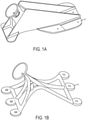
- Fig. 1a shows a jet engine nacelle compression pad 2 made by machining a block of titanium.
- Raw material for the pad may weigh about 15 pounds, while the pictured finished component may weight only 1.5 pounds.
- Fig. 1b shows a compression pad 4 for the same jet engine nacelle, produced by additive manufacturing. All raw material may be used in this design, and the design flexibility may allow a more structurally efficient configuration.
- the compression pad shown in Fig. 1b is not acceptable for use as a structural part in an engine.
- the additive manufacturing process produces a surface roughness average (Ra) of over 1,000 ⁇ M.
- Ra surface roughness average
- the compression pad has been designed with such complexity that machining may be cost prohibitive or even impossible.
- Example 1 (an example not part of the present invention as recited in the appended claims):
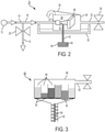
- Fig. 2 is a block diagram of an exemplary apparatus for fluid cavitation abrasive surface finishing, generally indicated at 10.
- a high-pressure pump 12 supplies pressurized water 14 along a conduit 16.
- a branching conduit 18 is regulated by a control valve 20.
- Such placement of the control valve allows precise control of the pressure and flow rate of water supplied along conduit 16 to a nozzle 22.
- Nozzle 22 is disposed in a pressurized tank 24 filled with water 26.
- Lid 28 of tank 24 may open to allow overflow from the tank into a catchment container 30.
- the lid may be coupled to tank 24 by a spring, or may be constrained by a weight, in order to maintain pressure in the tank.
- Water also drains from tank 24 along a conduit 32, regulated by a control valve 34.
- High pressure water 14 is injected by nozzle 22 into water 26 of tank 24 as a cavitating jet, which is directed toward a workpiece 36 submerged in tank 24.
- An interaction between the cavitating jet and water 26 form a swirling cavitation cloud 38, including a plurality of cavitation bubbles.
- Workpiece 36 may be disposed such that cavitation cloud 38 surrounds some or all of the workpiece, and collapsing cavitation bubbles impact a surface of the workpiece.
- the collapsing impact force of a cavitation bubble is determined in part by the pressure of injected water 14, the pressure of water 26 in tank 24, the ratio between the two pressures, and the temperature of water 14 and water 26 of tank 24.
- High pressure water 14 may be between 50 and 10,000 pounds per square inch, or any effective pressure. Preferably, water 14 may be at approximately 4,000 pounds per square inch when water 26 of tank 24 is at atmospheric pressure.
- a pressure and temperature sensor may be included in tank 24, or in any of conduits 12, 18, or 32.
- Control valves 20, 34 and lid 28 as well as high pressure pump 12 and a temperature control system may be connected to an electronic controller or other such component to allow precise, coordinated control of pressure and temperature conditions throughout apparatus 10.
- the cavitated fluid is water.
- any desired liquid may be used. Properties such as viscosity of the liquid used may affect collapsing force of cavitation bubbles and a liquid may be chosen to improve impact, or decrease the pressure required for a desired impact level.
- Any effective fluid flow device may be used to pump pressurized fluid through nozzle 22.
- an abrasive media 40 is introduced into cavitation cloud 38 between nozzle 22 and workpiece 36.
- the abrasive media is supplied by a conduit 42 from a hopper, or abrasive media source 44.
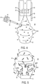
- An example of source 44 is shown in more detail in Fig. 3 .
- the source includes a sealed compartment 46 with multiple hoppers 48, each hopper housing a different type of abrasive media or abrading material.
- compartment 46 includes 6 hoppers with 6 abrasive media of decreasing grit size.
- Source 44 may include any desired types of media or number of types of media.
- the media may be of any grit size, preferably within a range of approximately 16 to 1200 ANSI grit size.
- Each hopper 48 includes a hopper door 50 that may be opened to introduce the desired media into conduit 42.
- Door 50 may be controlled manually, or may be actuated by an electronic controller integrated with other components of apparatus 10.
- Other simple switching mechanisms exist that may transition between delivery of different media, and any effective mechanism may be used.
- An air hose 52 is connected to source 44 to pressurize sealed compartment 46.
- Abrasive media 40 may thereby flow more freely and easily, and be urged into and along conduit 42.
- water or another liquid may be used in place of air to pressurize sealed compartment 46.
- a mechanism such as a push-rod may be used to induce abrasive media 40 to move through conduit 42.
- the abrasive media may be loose or may be in the form of a paste, or suspension.
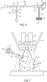
- Conduit 42 also includes a corkscrew structure 54, to induce a rotational or swirling motion to the media before the media is introduced to cavitation cloud 38, as shown in Fig. 4 .
- conduit 42 may be rotated other otherwise moved relative to cavitation cloud 38 while abrasive media 40 is being introduced to the cloud.
- Nozzle 22 is show in more detail in Fig. 4 , including a nozzle cap 56 disposed in a guide pipe 58.
- a cavitator 60 is spaced from a nozzle plate 62 by spacer 64, and positioned in nozzle cap 56 to alter flow of high pressure water 14 through nozzle 22.
- the change in flow rate of water 14 and interaction with tank water 26 may result in cavitation cloud 38.
- the plurality of cavitation bubbles comprising the cloud may swirl in a vortex, or tornado-like shape.
- Conduit 42 from abrasive media source 44 introduces a plurality of particles 66 of abrasive media 40 into cavitation cloud 38.
- Abrasive media 40 may gain speed, momentum, and kinetic energy from the cavitation cloud and mix with the cavitation bubbles.
- abrasive media 40 is introduced by a wide-angle nozzle 68, having at least a portion of outwardly diverging surfaces, at a distal end of conduit 42. As shown in Fig. 3 , abrasive media 40 is rotated by corkscrew 54 to facilitate mixing with cavitation cloud 38.
- Wide-angle nozzle 68 is disposed proximate an end of guide pipe 58 to saturate the greatest possible portion of cavitation cloud 38 with abrasive media 40.
- abrasive media 40 may be fed into cavitation cloud 38 by multiple conduits that are disposed at locations distributed around the cloud.
- nozzle 68 is shown oriented at an acute angle relative an axis defined by guide pipe 58. In other examples, nozzle 68 may be oriented perpendicular the axis or at an oblique angle. Any type of nozzle may be used with conduit 42.
- Source 44 may also include any appropriate delivery system or dispensing device for the abrasive media being used in apparatus 10.
- abrasive media 40 is introduced at an edge of cavitation cloud 38, into the swirling cavitation bubbles.
- abrasive media 40 may be introduced near a center of cavitation cloud 38, or into water 26 of tank 24 just outside of cavitation cloud 38, or at any point that promotes effective mixing of the abrasive media and the cavitation bubbles.
- Fig. 5 shows workpiece 36 supported by a stage 70, in a swirling mixture of cavitation bubbles and abrasive media 40.
- Nozzle 22, not shown in Fig. 5 may be directed toward stage 70.
- particles 66 of the media may be excited and energized.
- the micro-jets created by collapsing bubbles may collectively accelerate the motion of particles 66.
- particles 66 may impact the surface and remove material. That is, abrasive media 40 may be acted on by the high forces of the cavitation cloud to smooth rough surface 72.
- the swirling and multi-directional motion of cavitation cloud 38 may bring abrasive media 40 into contact with tight corners, crevices, and internal features of surface 72 as well as exposed upper areas.
- Normal cavitation peening may also occur, as the cavitation bubbles interact directly with surface 72 of workpiece 36.
- Surface 72 may be thereby peened, improving residual stress and fatigue strength, and cleaned, ready for painting or use.
- Fig. 6 is a block diagram of an exemplary apparatus of the current invention for fluid cavitation abrasive surface finishing, generally indicated at 110. Components similar to apparatus 10 as described above, are labeled with corresponding reference numbers. As shown, high-pressure pump 112 supplies pressurized water 114 along a conduit 116 to a nozzle 122. A branching conduit 118 is regulated by a control valve 120.
- Nozzle 122 is directed toward a workpiece 136 that is disposed in an air environment.
- the nozzle delivers two streams of water, a high pressure inner cavitation jet and a lower pressure outer jet.
- a cavitation cloud 138 may be thereby generated by nozzle 122, which may be referred to as a co-flow nozzle.
- Abrasive media 140 is introduced into cavitation cloud 138 between nozzle 122 and workpiece 136.
- the abrasive media is supplied by a conduit 142 from a source 144.
- Fig. 7 illustrates in more detail the resultant mixture of cavitation bubbles and abrasive media 140.
- co-flow nozzle 122 includes an inner nozzle 174 to generate inner cavitating jet 176 and an outer nozzle 178 to generate lower pressure outer jet 180.
- Inner nozzle 174 includes a cavitator 160, a spacer 164, and a nozzle plate 162 to alter the flow of high pressure water 114 and create cavitation cloud 138, while outer nozzle 178 has geometry appropriate to lower the pressure of water 114 for outer jet 180. That is, inner nozzle 174 defines an inner channel for cavitating jet 176, and an outer channel is for outer jet 180 defined between inner nozzle 174 and outer nozzle 178.
- co-flow nozzle 122 may be separately supplied with lower pressure water in addition to high pressure water 114 from pump 112 as shown in Fig. 6 .
- the outer jet forms a shell of water or liquid environment substantially surrounding the cavitation jet and resulting cavitation cloud 138.
- Abrasive media 140 is introduced by a wide-angle nozzle 168, and energized by the cloud.
- a portion of a rough surface 172 of workpiece 136 may be finished and peened by abrasive media 140 and cavitation cloud 138.
- apparatus 110 may be configured for use while fixed, or stationary.
- Workpiece 136 may be fully surrounded in cavitation cloud 138.
- workpiece 136 may be supported by a moving stage, to bring new portions of surface 72 into cavitation cloud 138 as surface finishing is completed.
- apparatus 110 may be integrated into a wand or other movable structure, to allow an operator to direct nozzle 122 as desired.
- apparatus 110 may be appropriate for spot-treatment, or finishing of repair work.
- the apparatus may be configured for transport to a work-site, may include an adaptor or connector to accept pressurized water from a variety of external systems, or may be otherwise made portable.
- apparatus 110 may be appropriate for use on large-scale projects, where it would be prohibitive to submerge workpieces in a tank of liquid.
- Figs. 8a-d illustrate a surface 210 undergoing a multi-stage fluid cavitation abrasive surface finishing process.
- a first abrasive media 212 energized by a cavitation cloud interacts with protruding peaks 214 of surface 210, removing material from the surface and lowering the peaks.
- Fig. 8b shows a second abrasive media 216 interacting with surface 210, which has been smoothed to some extent.
- Second media 214 has a smaller grit size than first media 212, allowing the energized media to further smooth surface 210 and reduce protruding peaks 214.
- a third abrasive media 218 removes additional material and further smooths surface 210, as shown in Fig. 8C .
- surface 210 has been finished to a desired level of smoothness. Any number of different media may be used for such a multi-stage process, in any number of stages.
- Abrasive media 212, 216, 218 may include particles of any effective material, of any grit size, or may include a mixture of materials.
- a media may include metal, glass, ceramic, silica oxide, aluminum oxide, pumice, nut shells, corn cob, or plastic abrasive particles.
- Each media may include particles preferably within a range of approximately 16 to 1200 ANSI grit size.
- abrasive media source 44 may be configured to deliver multiple abrasive media. Transition between media may be controlled by an operator or may be timed, actuated by a sensor, or otherwise triggered as part of an automatic multi-stage fluid cavitation abrasive surface finishing process.
- a most effective combination of media may be selected from a plurality of materials available in source 44 based on the material and roughness of a particular surface to be finished.
- source 44 may be stocked with appropriate media for a particular surface at time of processing. For example, a metal surface with Ra 100 ⁇ M may be finished with glass abrasives of 100 and 500 grit sizes while a plastic surface with Ra 1,000 ⁇ M may be finished with nut shell abrasives of 10 grit size, and then pumice abrasives of 50 and 100 grit sizes.
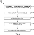
- Fig. 9 describes multiple steps of a method, generally indicated at 300, for surface finishing.
- Method 300 may be used in conjunction with any of the apparatuses, nozzles, or processes described in reference to Figs. 1-8 .
- steps of method 300 are described below and depicted in Fig. 9 , the steps need not necessarily all be performed, in some cases may be performed in a different order than the order shown, and in some cases may be performed simultaneously.
- First step 302 of method 300 includes discharging a flow of liquid toward a workpiece, in a liquid environment.
- the liquid may be discharged at a pressure and a flow rate that facilitates step 304, which includes forming a plurality of cavitation bubbles.
- the liquid may be discharged from a nozzle, configured to alter pressure and flow rate in a manner that generates a cloud of cavitation bubbles.
- the liquid may be discharged at a high pressure, preferably between 50 and 10,000 pounds per square inch. Either or both of the discharged liquid and the liquid environment may be water.
- Discharging the flow of liquid includes pumping a first liquid stream at a first pressure and a second liquid stream at a second, lower pressure.
- the first liquid stream is contained by the second liquid stream.
- Discharging the flow of liquid toward the workpiece may include surrounding the workpiece with the generated cloud of cavitation bubbles, or may include directing the flow to a portion of a surface of the workpiece.
- the workpiece may be supported by a stage, and the nozzle may be directed toward the stage or the workpiece.
- Step 306 of method 300 includes introducing abrasive media into the plurality of cavitation bubbles. Introducing the abrasive media may form a mixture of cavitation bubbles and abrasive media that is directed toward the workpiece.
- the abrasive media may be channeled through a conduit leading from a source, and may move through a corkscrew structure in the conduit. The media may then be dispersed through a wide-angle nozzle at a distal end of the conduit, the nozzle directed toward cavitation bubbles.
- the conduit may rotate or otherwise move as the abrasive media is introduced.
- the abrasive media source may be pressurized to induce movement of the abrasive media through the conduit.
- abrasive media may be channeled through multiple conduits from the abrasive media source or from multiple sources.
- the abrasive media may include particles of one or more of metal, glass, ceramic, silica oxide, aluminum oxide, pumice, nut shells, corn cob, and plastic abrasives.
- the included particles may be within a dimensional range of approximately 16 to 1200 ANSI grit size. Any effect abrasive media, combination of media, or mixture of media or particles may be used.
- step 306 of introducing abrasive media may be repeated for a series of abrasive media with descending grit sizes.
- Step 308 includes exciting the abrasive media with the cavitation bubbles.
- the cavitation cloud formed by the cavitation bubbles may have a swirling, vortex motion that imparts speed, momentum, and kinetic energy to the abrasive media.
- the cavitation bubbles may also collapse, collectively accelerating the motion of the abrasive media to achieve a high speed and sufficient kinetic energy to remove material from a surface of the workpiece upon impact, thereby facilitating step 310 of method 300 which includes removing material from the workpiece.
- cavitation cloud and bubbles impart a swirling and multi-directional motion to the abrasive media, material may be removed from tight corners, crevices, and internal features of the workpiece.
- the cavitation bubbles may further perform cavitation peening and cleaning of the surface of the workpiece.
Description
- This disclosure relates to surface finishing. More specifically, the disclosed examples relate to systems and methods for subtractive material finishing, cleaning, and peening with a cavitated fluid.
- Additive manufacturing methods such as directed energy deposition and powder bed melting have enabled efficient manufacturing of new components with complex shapes and features which are not practical or feasible to manufacture by previous methods. However, the resulting surface finish on products made by additive manufacturing is rougher than parts produced by traditional manufacturing methods. Electron beam powder bed melting can create a surface roughness average (Ra) over 1,000 µM, which is more than 10 times the smooth finish required for typical structural airplane components. Machining is cost-prohibitive or not possible for complex additive manufactured components, and surface finishing methods such as grit blasting, chemical milling, and shot peening do not sufficiently improve the surface roughness.
- Cavitation peening is a promising new method of mechanically treating a surface. Cavitation bubbles are formed in a fluid by a transition to gas phase resulting from an increase in flow velocity, then collapse as the flow velocity decreases. When a cavitation bubble collapses, a micro-jet is produced that can have a speed of 1,500 m/s in some examples. As disclosed in Soyama
US6855208 B1 , injecting a high speed water jet, or cavitating jet into water produces a cavitation cloud. The cavitation bubbles move in a vortex and the multi-directional impacts of the resultant micro-jets harden a surface better than shot peening. However, while cavitation peening cleans and enhances fatigue strength, surface roughness is not improved sufficiently for many applications. -
US 2005/139697 A1 in the abstract states "A fluid discharge apparatus adapted to discharge a cavitating stream of pressurized liquid along with the selective discharge of a secondary material, such as an abrasive, for removing dirt, debris, barnacles, marine growth, and other substances from submerged surfaces is provided. More particularly, the invention contemplates a introducing a pressurized liquid into a cavitation generating chamber to create and discharge a cavitating stream, and a secondary inlet for injecting abrasive material, such as silica, into the chamber to improve cleaning effectiveness. The gas bubbles within the cavitating liquid stream that essentially explode upon impacting debris resulting in tremendous pressure fluxuations provides improved effectiveness in removing debris and aquatic growth from the submerged surface. The combination of a secondary substance, such as an abrasive material, foam, or compressed gas enhances cleaning effectiveness. The invention further improves upon the control of such devices with controls, such as a pistol grip or rotational grip controllers, that allow the diver/operator to adjust flow rates and thrust without releasing his grasp. An improved hand-held apparatus is disclosed with a pistol grip and trigger actuator, and an improved wheeled vehicle is disclosed with improved control handles adapted to actuate valves and closure ports." -
EP 2546026 A1 in the abstract states "A processing apparatus is provided to process a workpiece. The processing apparatus can have a low-profile nozzle system capable of navigating through spaces in order to process target regions with relatively small clearances. A fluid jet outputted from the nozzle system is used to cut, mill, or otherwise process the target region of the workpiece." - The present invention is set out in the
independent claims 1 and 12, with some optional features set out in the claims dependent thereto. -
-
Fig. 1a is an isometric view of a jet engine nacelle compression pad created by a machining process. -
Fig. 1b is an isometric view of a jet engine nacelle compression pad created by an additive manufacturing process. -
Fig. 2 is a block diagram of an example of a fluid cavitation abrasive surface finishing apparatus, which example is not part of the present invention as recited in the appended claims. -
Fig. 3 is a diagrammatic illustration of an example of an abrasive media source. -
Fig. 4 is a diagrammatic illustration of the creation of an abrasive cavitation cloud, by an apparatus of the type shown inFig. 2 . -
Fig. 5 is a diagrammatic illustration of a workpiece undergoing surface finishing in the abrasive cavitation cloud ofFig. 4 . -
Fig. 6 is a block diagram of an example of a fluid cavitation abrasive surface finishing apparatus, the example being part of the present invention as recited in the appended claims. -
Fig. 7 is a diagrammatic illustration of a surface undergoing finishing by an apparatus of the type shown inFig. 6 . -
Figs. 8A-8D are schematic diagrams of abrasive media of different sizes being used to remove surface roughness from a surface of a work piece. -
Fig. 9 is a flow chart illustrating a method of material removal. - Various embodiments of a surface finishing method and apparatus having a fluid flow device and abrasive media are described below and illustrated in the associated drawings. Unless otherwise specified, a surface finishing apparatus and/or its various components may, but are not required to, contain at least one of the structure, components, functionality, and/or variations described, illustrated, and/or incorporated herein. Furthermore, the structures, components, functionalities, and/or variations described, illustrated, and/or incorporated herein in connection with the present teachings may, but are not required to, be included in other surface finishing apparatuses. The following description of various embodiments is merely exemplary in nature and is in no way intended to limit the disclosure, its application, or uses. Additionally, the advantages provided by the embodiments, as described below, are illustrative in nature and not all embodiments provide the same advantages or the same degree of advantages.
-
Fig. 1a shows a jet enginenacelle compression pad 2 made by machining a block of titanium. Raw material for the pad may weigh about 15 pounds, while the pictured finished component may weight only 1.5 pounds. By contrast,Fig. 1b shows a compression pad 4 for the same jet engine nacelle, produced by additive manufacturing. All raw material may be used in this design, and the design flexibility may allow a more structurally efficient configuration. - However, as built, the compression pad shown in
Fig. 1b is not acceptable for use as a structural part in an engine. The additive manufacturing process produces a surface roughness average (Ra) of over 1,000 µM. It should be noted that the compression pad has been designed with such complexity that machining may be cost prohibitive or even impossible. - The improvement in manufacturing efficiency and design freedom offered by additive manufacturing is highly desirable across a wide range of disciplines, to reduce costs and enable new technologies. Surface roughness is a major obstacle to the adoption of such techniques, which may be overcome by fluid cavitation abrasive surface finishing.
-
Fig. 2 is a block diagram of an exemplary apparatus for fluid cavitation abrasive surface finishing, generally indicated at 10. A high-pressure pump 12 supplies pressurizedwater 14 along aconduit 16. A branchingconduit 18 is regulated by acontrol valve 20. Such placement of the control valve allows precise control of the pressure and flow rate of water supplied alongconduit 16 to anozzle 22. -
Nozzle 22 is disposed in a pressurizedtank 24 filled withwater 26.Lid 28 oftank 24 may open to allow overflow from the tank into acatchment container 30. The lid may be coupled to tank 24 by a spring, or may be constrained by a weight, in order to maintain pressure in the tank. Water also drains fromtank 24 along aconduit 32, regulated by acontrol valve 34. -
High pressure water 14 is injected bynozzle 22 intowater 26 oftank 24 as a cavitating jet, which is directed toward aworkpiece 36 submerged intank 24. An interaction between the cavitating jet andwater 26 form a swirlingcavitation cloud 38, including a plurality of cavitation bubbles.Workpiece 36 may be disposed such thatcavitation cloud 38 surrounds some or all of the workpiece, and collapsing cavitation bubbles impact a surface of the workpiece. The collapsing impact force of a cavitation bubble is determined in part by the pressure of injectedwater 14, the pressure ofwater 26 intank 24, the ratio between the two pressures, and the temperature ofwater 14 andwater 26 oftank 24.High pressure water 14 may be between 50 and 10,000 pounds per square inch, or any effective pressure. Preferably,water 14 may be at approximately 4,000 pounds per square inch whenwater 26 oftank 24 is at atmospheric pressure. - To optimize these parameters, a pressure and temperature sensor may be included in
tank 24, or in any ofconduits Control valves lid 28 as well ashigh pressure pump 12 and a temperature control system may be connected to an electronic controller or other such component to allow precise, coordinated control of pressure and temperature conditions throughoutapparatus 10. - In the pictured example, the cavitated fluid is water. However, any desired liquid may be used. Properties such as viscosity of the liquid used may affect collapsing force of cavitation bubbles and a liquid may be chosen to improve impact, or decrease the pressure required for a desired impact level. Any effective fluid flow device may be used to pump pressurized fluid through
nozzle 22. - As shown in
Fig. 2 , anabrasive media 40 is introduced intocavitation cloud 38 betweennozzle 22 andworkpiece 36. The abrasive media is supplied by aconduit 42 from a hopper, orabrasive media source 44. An example ofsource 44 is shown in more detail inFig. 3 . The source includes a sealedcompartment 46 withmultiple hoppers 48, each hopper housing a different type of abrasive media or abrading material. In the pictured example,compartment 46 includes 6 hoppers with 6 abrasive media of decreasing grit size.Source 44 may include any desired types of media or number of types of media. The media may be of any grit size, preferably within a range of approximately 16 to 1200 ANSI grit size. - Each
hopper 48 includes ahopper door 50 that may be opened to introduce the desired media intoconduit 42.Door 50 may be controlled manually, or may be actuated by an electronic controller integrated with other components ofapparatus 10. Other simple switching mechanisms exist that may transition between delivery of different media, and any effective mechanism may be used. - An
air hose 52 is connected to source 44 to pressurize sealedcompartment 46.Abrasive media 40 may thereby flow more freely and easily, and be urged into and alongconduit 42. In some examples, water or another liquid may be used in place of air to pressurize sealedcompartment 46. In other examples, a mechanism such as a push-rod may be used to induceabrasive media 40 to move throughconduit 42. The abrasive media may be loose or may be in the form of a paste, or suspension. -
Conduit 42 also includes acorkscrew structure 54, to induce a rotational or swirling motion to the media before the media is introduced tocavitation cloud 38, as shown inFig. 4 . In some examples,conduit 42 may be rotated other otherwise moved relative tocavitation cloud 38 whileabrasive media 40 is being introduced to the cloud. -
Nozzle 22 is show in more detail inFig. 4 , including anozzle cap 56 disposed in aguide pipe 58. Acavitator 60 is spaced from anozzle plate 62 byspacer 64, and positioned innozzle cap 56 to alter flow ofhigh pressure water 14 throughnozzle 22. The change in flow rate ofwater 14 and interaction withtank water 26 may result incavitation cloud 38. The plurality of cavitation bubbles comprising the cloud may swirl in a vortex, or tornado-like shape. -
Conduit 42 fromabrasive media source 44 introduces a plurality ofparticles 66 ofabrasive media 40 intocavitation cloud 38.Abrasive media 40 may gain speed, momentum, and kinetic energy from the cavitation cloud and mix with the cavitation bubbles. In the pictured example,abrasive media 40 is introduced by a wide-angle nozzle 68, having at least a portion of outwardly diverging surfaces, at a distal end ofconduit 42. As shown inFig. 3 ,abrasive media 40 is rotated bycorkscrew 54 to facilitate mixing withcavitation cloud 38. Wide-angle nozzle 68 is disposed proximate an end ofguide pipe 58 to saturate the greatest possible portion ofcavitation cloud 38 withabrasive media 40. - In other examples,
abrasive media 40 may be fed intocavitation cloud 38 by multiple conduits that are disposed at locations distributed around the cloud. InFig. 4 ,nozzle 68 is shown oriented at an acute angle relative an axis defined byguide pipe 58. In other examples,nozzle 68 may be oriented perpendicular the axis or at an oblique angle. Any type of nozzle may be used withconduit 42.Source 44 may also include any appropriate delivery system or dispensing device for the abrasive media being used inapparatus 10. - In the pictured example,
abrasive media 40 is introduced at an edge ofcavitation cloud 38, into the swirling cavitation bubbles. In other examples,abrasive media 40 may be introduced near a center ofcavitation cloud 38, or intowater 26 oftank 24 just outside ofcavitation cloud 38, or at any point that promotes effective mixing of the abrasive media and the cavitation bubbles. -
Fig. 5 showsworkpiece 36 supported by astage 70, in a swirling mixture of cavitation bubbles andabrasive media 40.Nozzle 22, not shown inFig. 5 , may be directed towardstage 70. As the bubbles of the mixture collapse,particles 66 of the media may be excited and energized. The micro-jets created by collapsing bubbles may collectively accelerate the motion ofparticles 66. As the mixture of bubbles and media contacts arough surface 72 ofworkpiece 36,particles 66 may impact the surface and remove material. That is,abrasive media 40 may be acted on by the high forces of the cavitation cloud to smoothrough surface 72. The swirling and multi-directional motion ofcavitation cloud 38 may bringabrasive media 40 into contact with tight corners, crevices, and internal features ofsurface 72 as well as exposed upper areas. - Normal cavitation peening may also occur, as the cavitation bubbles interact directly with
surface 72 ofworkpiece 36.Surface 72 may be thereby peened, improving residual stress and fatigue strength, and cleaned, ready for painting or use. -
Fig. 6 is a block diagram of an exemplary apparatus of the current invention for fluid cavitation abrasive surface finishing, generally indicated at 110. Components similar toapparatus 10 as described above, are labeled with corresponding reference numbers. As shown, high-pressure pump 112 supplies pressurizedwater 114 along aconduit 116 to anozzle 122. A branchingconduit 118 is regulated by acontrol valve 120. -
Nozzle 122 is directed toward aworkpiece 136 that is disposed in an air environment. The nozzle delivers two streams of water, a high pressure inner cavitation jet and a lower pressure outer jet. Acavitation cloud 138 may be thereby generated bynozzle 122, which may be referred to as a co-flow nozzle. -
Abrasive media 140 is introduced intocavitation cloud 138 betweennozzle 122 andworkpiece 136. The abrasive media is supplied by aconduit 142 from asource 144.Fig. 7 illustrates in more detail the resultant mixture of cavitation bubbles andabrasive media 140. - As shown in
Fig. 7 ,co-flow nozzle 122 includes aninner nozzle 174 to generateinner cavitating jet 176 and anouter nozzle 178 to generate lower pressureouter jet 180.Inner nozzle 174 includes acavitator 160, aspacer 164, and anozzle plate 162 to alter the flow ofhigh pressure water 114 and createcavitation cloud 138, whileouter nozzle 178 has geometry appropriate to lower the pressure ofwater 114 forouter jet 180. That is,inner nozzle 174 defines an inner channel forcavitating jet 176, and an outer channel is forouter jet 180 defined betweeninner nozzle 174 andouter nozzle 178. In some examples,co-flow nozzle 122 may be separately supplied with lower pressure water in addition tohigh pressure water 114 frompump 112 as shown inFig. 6 . - Referring again to
Fig. 7 , ascavitation jet 176 andouter jet 180 leaveco-flow nozzle 122, the outer jet forms a shell of water or liquid environment substantially surrounding the cavitation jet and resultingcavitation cloud 138.Abrasive media 140 is introduced by a wide-angle nozzle 168, and energized by the cloud. A portion of arough surface 172 ofworkpiece 136 may be finished and peened byabrasive media 140 andcavitation cloud 138. - In some examples,
apparatus 110 may be configured for use while fixed, or stationary.Workpiece 136 may be fully surrounded incavitation cloud 138. Alternatively,workpiece 136 may be supported by a moving stage, to bring new portions ofsurface 72 intocavitation cloud 138 as surface finishing is completed. In other examples,apparatus 110 may be integrated into a wand or other movable structure, to allow an operator to directnozzle 122 as desired. - In some examples,
apparatus 110 may be appropriate for spot-treatment, or finishing of repair work. The apparatus may be configured for transport to a work-site, may include an adaptor or connector to accept pressurized water from a variety of external systems, or may be otherwise made portable. In other examples,apparatus 110 may be appropriate for use on large-scale projects, where it would be prohibitive to submerge workpieces in a tank of liquid. -
Figs. 8a-d illustrate asurface 210 undergoing a multi-stage fluid cavitation abrasive surface finishing process. InFig. 8a , a firstabrasive media 212 energized by a cavitation cloud interacts with protrudingpeaks 214 ofsurface 210, removing material from the surface and lowering the peaks. -
Fig. 8b shows a secondabrasive media 216 interacting withsurface 210, which has been smoothed to some extent.Second media 214 has a smaller grit size thanfirst media 212, allowing the energized media to furthersmooth surface 210 and reduce protrudingpeaks 214. Similarly, a thirdabrasive media 218 removes additional material and further smoothssurface 210, as shown inFig. 8C . Finally, as shown inFig. 8D ,surface 210 has been finished to a desired level of smoothness. Any number of different media may be used for such a multi-stage process, in any number of stages. -
Abrasive media - As previously discussed and shown in
Fig. 3 ,abrasive media source 44 may be configured to deliver multiple abrasive media. Transition between media may be controlled by an operator or may be timed, actuated by a sensor, or otherwise triggered as part of an automatic multi-stage fluid cavitation abrasive surface finishing process. - A most effective combination of media may be selected from a plurality of materials available in
source 44 based on the material and roughness of a particular surface to be finished. Alternatively,source 44 may be stocked with appropriate media for a particular surface at time of processing. For example, a metal surface with Ra 100 µM may be finished with glass abrasives of 100 and 500 grit sizes while a plastic surface with Ra 1,000 µM may be finished with nut shell abrasives of 10 grit size, and then pumice abrasives of 50 and 100 grit sizes. -
Fig. 9 describes multiple steps of a method, generally indicated at 300, for surface finishing.Method 300 may be used in conjunction with any of the apparatuses, nozzles, or processes described in reference toFigs. 1-8 . Although various steps ofmethod 300 are described below and depicted inFig. 9 , the steps need not necessarily all be performed, in some cases may be performed in a different order than the order shown, and in some cases may be performed simultaneously. -
First step 302 ofmethod 300 includes discharging a flow of liquid toward a workpiece, in a liquid environment. The liquid may be discharged at a pressure and a flow rate that facilitatesstep 304, which includes forming a plurality of cavitation bubbles. The liquid may be discharged from a nozzle, configured to alter pressure and flow rate in a manner that generates a cloud of cavitation bubbles. - The liquid may be discharged at a high pressure, preferably between 50 and 10,000 pounds per square inch. Either or both of the discharged liquid and the liquid environment may be water.
- Discharging the flow of liquid includes pumping a first liquid stream at a first pressure and a second liquid stream at a second, lower pressure. The first liquid stream is contained by the second liquid stream.
- Discharging the flow of liquid toward the workpiece may include surrounding the workpiece with the generated cloud of cavitation bubbles, or may include directing the flow to a portion of a surface of the workpiece. The workpiece may be supported by a stage, and the nozzle may be directed toward the stage or the workpiece.
- Step 306 of
method 300 includes introducing abrasive media into the plurality of cavitation bubbles. Introducing the abrasive media may form a mixture of cavitation bubbles and abrasive media that is directed toward the workpiece. - The abrasive media may be channeled through a conduit leading from a source, and may move through a corkscrew structure in the conduit. The media may then be dispersed through a wide-angle nozzle at a distal end of the conduit, the nozzle directed toward cavitation bubbles. The conduit may rotate or otherwise move as the abrasive media is introduced. The abrasive media source may be pressurized to induce movement of the abrasive media through the conduit. In some examples, abrasive media may be channeled through multiple conduits from the abrasive media source or from multiple sources.
- The abrasive media may include particles of one or more of metal, glass, ceramic, silica oxide, aluminum oxide, pumice, nut shells, corn cob, and plastic abrasives. Preferably, the included particles may be within a dimensional range of approximately 16 to 1200 ANSI grit size. Any effect abrasive media, combination of media, or mixture of media or particles may be used. In some examples, step 306 of introducing abrasive media may be repeated for a series of abrasive media with descending grit sizes.
- Step 308 includes exciting the abrasive media with the cavitation bubbles. The cavitation cloud formed by the cavitation bubbles may have a swirling, vortex motion that imparts speed, momentum, and kinetic energy to the abrasive media. The cavitation bubbles may also collapse, collectively accelerating the motion of the abrasive media to achieve a high speed and sufficient kinetic energy to remove material from a surface of the workpiece upon impact, thereby facilitating
step 310 ofmethod 300 which includes removing material from the workpiece. - Since the cavitation cloud and bubbles impart a swirling and multi-directional motion to the abrasive media, material may be removed from tight corners, crevices, and internal features of the workpiece. The cavitation bubbles may further perform cavitation peening and cleaning of the surface of the workpiece.
Claims (12)
- A method of material removal, comprising:discharging a flow of liquid towards a workpiece (136) at a pressure and a flow rate that facilitates forming a plurality of cavitation bubbles (138),introducing abrasive media (140) into the plurality of cavitation bubbles,exciting the abrasive media with the cavitation bubbles, and removing material from the workpiece based on an interaction between the cavitation bubbles with the abrasive media and a surface of the workpiece; wherein the method is carried out in a liquid environment; and wherein the discharging step includes pumping a first liquid stream (176) at a first pressure level for forming the plurality of cavitation bubbles, the liquid environment comprising a second stream of liquid (180) surrounding the first stream at a second pressure level, the second pressure level being lower than the first pressure level.
- The method of claim 1, wherein the liquid comprises water (114).
- The method of any one of claims 1-2, wherein the introducing step includes channeling abrasive media from a source into the plurality of cavitation bubbles.
- The method of any one of claims 1-3, wherein the abrasive media includes particles comprising one or more of (a) metal, (b) glass, (c) ceramic, (d) silica oxide, (e) aluminum oxide, (f) pumice, (g) nut shells, (h) corn cob, and (i) plastic abrasives.
- The method of any of claims 1-4, wherein the abrasive media includes particles in a dimensional range of approximately 16 to 1200 ANSI Grit Size.
- The method of any of claims 1-5, further comprising
channeling the abrasive media through a conduit (142) leading from a source of the abrasive media to the plurality of cavitation bubbles. - The method of claim 6, further comprising:
rotating or otherwise actuating movement of the conduit during the introducing step. - The method of claim 7, further comprising:
moving the abrasive media through a corkscrew structure (54) in the conduit. - The method of any of claims 5-8, further comprising:
dispersing the abrasive media through a wide angle nozzle (168) at a distal end of the conduit. - The method of any of claims 1-9, further comprising:
channeling the abrasive media through plural conduits into the plurality of cavitation bubbles. - The method of any of claims 1-10, wherein the discharging step is performed at a pressure in a range of 50 to 10,000 pounds per square inch.
- An apparatus (110) to remove material from a workpiece (136) operable to perform the method of any of claims 1-11, the apparatus comprising a liquid flow device configured to pump liquid through a nozzle (122) generating a plurality of cavitation bubbles (138) directed towards the workpiece, and
an abrasive media dispensing device (144) configured to deliver abrasive media (140) into the cavitation bubbles generated by the liquid flow device; wherein the liquid flow device includes a nozzle (122) having an inner channel configured to supply the first liquid stream (176) at the first pressure level sufficient to generate the plurality of cavitation bubbles, and an outer channel configured to supply the second liquid stream (180) at the second pressure level, the second pressure level being below the first pressure level, and wherein the second liquid stream substantially surrounds the first liquid stream.
Applications Claiming Priority (1)
| Application Number | Priority Date | Filing Date | Title |
|---|---|---|---|
| US15/693,401 US10836012B2 (en) | 2017-08-31 | 2017-08-31 | Method and apparatus for fluid cavitation abrasive surface finishing |
Publications (2)
| Publication Number | Publication Date |
|---|---|
| EP3450104A1 EP3450104A1 (en) | 2019-03-06 |
| EP3450104B1 true EP3450104B1 (en) | 2022-01-26 |
Family
ID=63350473
Family Applications (1)
| Application Number | Title | Priority Date | Filing Date |
|---|---|---|---|
| EP18190086.1A Active EP3450104B1 (en) | 2017-08-31 | 2018-08-21 | Method and apparatus for fluid cavitation abrasive surface finishing |
Country Status (7)
| Country | Link |
|---|---|
| US (1) | US10836012B2 (en) |
| EP (1) | EP3450104B1 (en) |
| JP (1) | JP7251938B2 (en) |
| KR (1) | KR102569456B1 (en) |
| CN (1) | CN109719631B (en) |
| CA (1) | CA3010954C (en) |
| RU (1) | RU2018125395A (en) |
Families Citing this family (13)
| Publication number | Priority date | Publication date | Assignee | Title |
|---|---|---|---|---|
| US11679454B2 (en) | 2017-08-31 | 2023-06-20 | The Boeing Company | Portable cavitation peening method and apparatus |
| GB2573012A (en) * | 2018-04-20 | 2019-10-23 | Zeeko Innovations Ltd | Fluid jet processing |
| US11633835B2 (en) | 2018-12-14 | 2023-04-25 | The Boeing Company | Systems for managing abrasive media in cavitated fluid |
| US11465259B2 (en) * | 2019-02-13 | 2022-10-11 | The Boeing Company | System and method for fluid cavitation processing a part |
| GB201905215D0 (en) * | 2019-04-12 | 2019-05-29 | Rolls Royce Plc | A method and apparatus for finishing a surface of a component |
| CN111843843A (en) * | 2020-06-16 | 2020-10-30 | 江苏大学 | Method for ultrasonic uniform cavitation shot blasting of mixed particle solution |
| CN111843853B (en) * | 2020-07-31 | 2021-08-03 | 山东大学 | Internal surface finish machining strengthening system based on hydrodynamic cavitation jet flow |
| JP7222958B2 (en) * | 2020-09-02 | 2023-02-15 | 株式会社スギノマシン | Abrasive peening device and abrasive peening method |
| DE102021101996A1 (en) | 2021-01-28 | 2022-07-28 | Dyemansion Gmbh | Process for post-processing of additively manufactured components by blasting with plastic blasting media |
| CN114734365B (en) * | 2022-06-13 | 2022-09-09 | 中国航发上海商用航空发动机制造有限责任公司 | Surface finishing method of micro inner flow passage, micro inner flow passage workpiece and finishing medium |
| CN115284160A (en) * | 2022-06-30 | 2022-11-04 | 江苏大学 | Reciprocating abrasive flow polishing device and method based on cavitation effect |
| GB2621042A (en) * | 2022-06-30 | 2024-01-31 | Univ Jiangsu | Reciprocating abrasive flow polishing apparatus and method based on cavitation effect |
| US20240001509A1 (en) * | 2022-07-01 | 2024-01-04 | The Boeing Company | Damage tolerant cavitation nozzle |
Family Cites Families (37)
| Publication number | Priority date | Publication date | Assignee | Title |
|---|---|---|---|---|
| US3807632A (en) | 1971-08-26 | 1974-04-30 | Hydronautics | System for eroding solids with a cavitating fluid jet |
| CA1128582A (en) | 1980-04-10 | 1982-07-27 | Geoffrey W. Vickers | Cavitation nozzle assembly |
| JPH03288581A (en) | 1990-04-03 | 1991-12-18 | Yoshihide Shibano | Spray type ultrasonic washing apparatus |
| JP3162104B2 (en) | 1991-06-10 | 2001-04-25 | 株式会社日立製作所 | Method for improving residual stress of metallic materials |
| JP2000263337A (en) | 1999-01-13 | 2000-09-26 | Japan Science & Technology Corp | Surface refining method of metal part, washing method and device |
| JP4240972B2 (en) | 1999-01-13 | 2009-03-18 | 独立行政法人科学技術振興機構 | Method and apparatus for surface modification and cleaning of metal parts and the like |
| JP3803734B2 (en) | 1999-01-26 | 2006-08-02 | 株式会社日立製作所 | Water jet peening equipment |
| US6280302B1 (en) | 1999-03-24 | 2001-08-28 | Flow International Corporation | Method and apparatus for fluid jet formation |
| WO2001015866A1 (en) | 1999-09-01 | 2001-03-08 | Siemens Aktiengesellschaft | Method and device for treating the surface of a part |
| JP4169239B2 (en) | 2000-10-05 | 2008-10-22 | 株式会社スギノマシン | Submerged surface processing apparatus and processing method |
| JP2003062492A (en) | 2001-08-23 | 2003-03-04 | Japan Science & Technology Corp | Surface treatment and cleaning methods for mechanical part, etc., and apparatus therefor |
| US20050017090A1 (en) * | 2003-03-25 | 2005-01-27 | Pivovarov Alexander R. | Cleaning of submerged surfaces by discharge of pressurized cavitating fluids |
| US7494073B2 (en) * | 2003-03-25 | 2009-02-24 | Alexander Pivovarov | Cleaning of submerged surfaces by discharge of pressurized cavitating fluids |
| US20050139697A1 (en) * | 2003-03-25 | 2005-06-30 | Alexander Pivovarov | Cleaning of submerged surfaces by discharge of pressurized cavitating fluids |
| US6993948B2 (en) | 2003-06-13 | 2006-02-07 | General Electric Company | Methods for altering residual stresses using mechanically induced liquid cavitation |
| JP4581910B2 (en) | 2005-08-19 | 2010-11-17 | 株式会社デンソー | Hole surface processing method |
| JP2007090491A (en) | 2005-09-29 | 2007-04-12 | Toshiba Corp | Water jet peening device and water jet peening method |
| JP4302097B2 (en) | 2005-12-06 | 2009-07-22 | 三菱重工業株式会社 | Decontamination apparatus and decontamination method |
| US20120118562A1 (en) * | 2006-11-13 | 2012-05-17 | Mcafee Wesley Mark | System, apparatus and method for abrasive jet fluid cutting |
| WO2009031517A1 (en) | 2007-09-03 | 2009-03-12 | National University Corporation Okayama University | Surface treating method and device thereof |
| US8448880B2 (en) | 2007-09-18 | 2013-05-28 | Flow International Corporation | Apparatus and process for formation of laterally directed fluid jets |
| JP5578318B2 (en) | 2010-05-26 | 2014-08-27 | 国立大学法人東北大学 | Cavitation generator |
| CN101886160B (en) * | 2010-07-06 | 2011-09-14 | 中国矿业大学 | Metal surface modification method through emulsion jet |
| US9062354B2 (en) * | 2011-02-24 | 2015-06-23 | General Electric Company | Surface treatment system, a surface treatment process and a system treated component |
| CN103415358B (en) | 2011-05-16 | 2015-08-26 | 新日铁住金工程技术株式会社 | The cleaning device of roll and clean method thereof |
| US9050642B2 (en) | 2011-09-27 | 2015-06-09 | Ormond, Llc | Method and apparatus for surface enhancement |
| JP5876701B2 (en) | 2011-10-07 | 2016-03-02 | Jfe条鋼株式会社 | Method for strengthening bolt marking tool and bolt marking tool |
| WO2013142851A1 (en) * | 2012-03-23 | 2013-09-26 | Wesley Mark Mcafee | System, apparatus and method for abrasive jet fluid cutting |
| JP6125261B2 (en) | 2013-02-12 | 2017-05-10 | 三菱重工業株式会社 | Water jet peening compressive residual stress test method |
| JP6169957B2 (en) | 2013-11-29 | 2017-07-26 | 三菱重工業株式会社 | Water jet peening pre-evaluation method, program for executing the method, apparatus for executing the method, and water jet peening construction method |
| US9200341B1 (en) * | 2014-07-18 | 2015-12-01 | The Boeing Company | Systems and methods of cavitation peening a workpiece |
| EP3259100B1 (en) | 2015-02-18 | 2020-10-14 | ANT Applied New Technologies AG | Abrasive waterjet cutting installation |
| JP6246761B2 (en) | 2015-06-02 | 2017-12-13 | Jfeスチール株式会社 | Manufacturing method of steel member for machine structure |
| CN106392863B (en) * | 2016-10-20 | 2019-03-26 | 浙江工业大学 | A kind of high efficiency fluid polishing processing method and device based on structure cavitation effect |
| US10265833B2 (en) * | 2017-08-31 | 2019-04-23 | The Boeing Company | Portable cavitation peening method and apparatus |
| GB201805763D0 (en) * | 2018-04-06 | 2018-05-23 | Rolls Royce Plc | A method and apparatus for finishing an internal channel of a component |
| CN108789165B (en) * | 2018-06-25 | 2020-02-07 | 南京航空航天大学 | Ultrasonic auxiliary abrasive jet deburring device |
-
2017
- 2017-08-31 US US15/693,401 patent/US10836012B2/en active Active
-
2018
- 2018-07-09 CA CA3010954A patent/CA3010954C/en active Active
- 2018-07-11 RU RU2018125395A patent/RU2018125395A/en unknown
- 2018-08-21 EP EP18190086.1A patent/EP3450104B1/en active Active
- 2018-08-28 CN CN201810984657.4A patent/CN109719631B/en active Active
- 2018-08-29 JP JP2018159850A patent/JP7251938B2/en active Active
- 2018-08-30 KR KR1020180102760A patent/KR102569456B1/en active IP Right Grant
Non-Patent Citations (1)
| Title |
|---|
| None * |
Also Published As
| Publication number | Publication date |
|---|---|
| CA3010954C (en) | 2022-09-20 |
| US20190061103A1 (en) | 2019-02-28 |
| CN109719631B (en) | 2022-04-12 |
| RU2018125395A (en) | 2020-01-13 |
| CA3010954A1 (en) | 2019-02-28 |
| EP3450104A1 (en) | 2019-03-06 |
| CN109719631A (en) | 2019-05-07 |
| KR102569456B1 (en) | 2023-08-21 |
| US10836012B2 (en) | 2020-11-17 |
| KR20190024828A (en) | 2019-03-08 |
| JP7251938B2 (en) | 2023-04-04 |
| RU2018125395A3 (en) | 2021-10-28 |
| JP2019072834A (en) | 2019-05-16 |
Similar Documents
| Publication | Publication Date | Title |
|---|---|---|
| EP3450104B1 (en) | Method and apparatus for fluid cavitation abrasive surface finishing | |
| JP6655679B2 (en) | Fluid jet cutting systems, components and methods that facilitate an improved working environment | |
| EP2542384B1 (en) | Abrasive jet systems, including abrasive jet systems utilizing fluid repelling materials, and associated methods | |
| CN105599919B (en) | Apparatus and method for additive manufacturing | |
| EP0994764B1 (en) | Method and apparatus for producing a high-velocity particle stream | |
| KR100504629B1 (en) | Method and apparatus for producing a high-velocity particle stream | |
| CN110026908B (en) | Ultrasonic cavitation auxiliary jet polishing system and polishing method | |
| KR20160110413A (en) | High-pressure waterjet cutting head systems, components and related methods | |
| EP3089849A1 (en) | Abrasive slurry delivery systems and methods | |
| JP2008307624A (en) | Apparatus and method for deburring and cleaning | |
| US20210178552A1 (en) | Device and method for the surface treatment of a material | |
| EP1150801B1 (en) | Method for removing surface coatings | |
| US10518385B2 (en) | Apparatus and process for surface treating interior of a workpiece | |
| CN112975581B (en) | Jet flow reinforced polishing integrated device and process | |
| JP2019081211A (en) | Surface treatment device and surface treatment method | |
| EP1323836A1 (en) | Method and apparatus for ultrahigh pressure water jet peening | |
| CN115741486B (en) | Ultrasonic-assisted nano abrasive particle water jet grooved heat pipe inner surface composite polishing device and method | |
| KR100569739B1 (en) | Process for working a quartz glass component | |
| CN117532408A (en) | Material-adding multiphase flow chemical mechanical polishing equipment and method for hollow space lattice | |
| CN106319429A (en) | Workpiece stage used for manufacturing nano diamond thin coating membrane | |
| JP2020019089A (en) | Injection nozzle device | |
| JPH09193013A (en) | Burr removing method | |
| KR20070020654A (en) | Jet nozzle for surface treatment | |
| JP2009018370A (en) | Method and apparatus for shot peening processing | |
| JP2004122296A (en) | Ice water blasting machine |
Legal Events
| Date | Code | Title | Description |
|---|---|---|---|
| PUAI | Public reference made under article 153(3) epc to a published international application that has entered the european phase |
Free format text: ORIGINAL CODE: 0009012 |
|
| STAA | Information on the status of an ep patent application or granted ep patent |
Free format text: STATUS: REQUEST FOR EXAMINATION WAS MADE |
|
| 17P | Request for examination filed |
Effective date: 20180821 |
|
| AK | Designated contracting states |
Kind code of ref document: A1 Designated state(s): AL AT BE BG CH CY CZ DE DK EE ES FI FR GB GR HR HU IE IS IT LI LT LU LV MC MK MT NL NO PL PT RO RS SE SI SK SM TR |
|
| AX | Request for extension of the european patent |
Extension state: BA ME |
|
| STAA | Information on the status of an ep patent application or granted ep patent |
Free format text: STATUS: EXAMINATION IS IN PROGRESS |
|
| 17Q | First examination report despatched |
Effective date: 20190730 |
|
| STAA | Information on the status of an ep patent application or granted ep patent |
Free format text: STATUS: EXAMINATION IS IN PROGRESS |
|
| GRAP | Despatch of communication of intention to grant a patent |
Free format text: ORIGINAL CODE: EPIDOSNIGR1 |
|
| STAA | Information on the status of an ep patent application or granted ep patent |
Free format text: STATUS: GRANT OF PATENT IS INTENDED |
|
| RIC1 | Information provided on ipc code assigned before grant |
Ipc: B33Y 40/00 20200101ALI20210326BHEP Ipc: B05B 7/04 20060101ALI20210326BHEP Ipc: B08B 3/02 20060101ALI20210326BHEP Ipc: B05B 12/04 20060101ALI20210326BHEP Ipc: B05B 7/14 20060101ALI20210326BHEP Ipc: B24C 7/00 20060101ALI20210326BHEP Ipc: B24C 1/08 20060101ALI20210326BHEP Ipc: B24C 1/06 20060101ALI20210326BHEP Ipc: B24C 1/10 20060101AFI20210326BHEP |
|
| INTG | Intention to grant announced |
Effective date: 20210430 |
|
| GRAJ | Information related to disapproval of communication of intention to grant by the applicant or resumption of examination proceedings by the epo deleted |
Free format text: ORIGINAL CODE: EPIDOSDIGR1 |
|
| STAA | Information on the status of an ep patent application or granted ep patent |
Free format text: STATUS: EXAMINATION IS IN PROGRESS |
|
| INTC | Intention to grant announced (deleted) | ||
| GRAP | Despatch of communication of intention to grant a patent |
Free format text: ORIGINAL CODE: EPIDOSNIGR1 |
|
| STAA | Information on the status of an ep patent application or granted ep patent |
Free format text: STATUS: GRANT OF PATENT IS INTENDED |
|
| INTG | Intention to grant announced |
Effective date: 20210921 |
|
| GRAS | Grant fee paid |
Free format text: ORIGINAL CODE: EPIDOSNIGR3 |
|
| GRAA | (expected) grant |
Free format text: ORIGINAL CODE: 0009210 |
|
| STAA | Information on the status of an ep patent application or granted ep patent |
Free format text: STATUS: THE PATENT HAS BEEN GRANTED |
|
| AK | Designated contracting states |
Kind code of ref document: B1 Designated state(s): AL AT BE BG CH CY CZ DE DK EE ES FI FR GB GR HR HU IE IS IT LI LT LU LV MC MK MT NL NO PL PT RO RS SE SI SK SM TR |
|
| REG | Reference to a national code |
Ref country code: GB Ref legal event code: FG4D |
|
| REG | Reference to a national code |
Ref country code: CH Ref legal event code: EP |
|
| REG | Reference to a national code |
Ref country code: AT Ref legal event code: REF Ref document number: 1464888 Country of ref document: AT Kind code of ref document: T Effective date: 20220215 |
|
| REG | Reference to a national code |
Ref country code: IE Ref legal event code: FG4D |
|
| REG | Reference to a national code |
Ref country code: DE Ref legal event code: R096 Ref document number: 602018029976 Country of ref document: DE |
|
| REG | Reference to a national code |
Ref country code: LT Ref legal event code: MG9D |
|
| REG | Reference to a national code |
Ref country code: NL Ref legal event code: MP Effective date: 20220126 |
|
| REG | Reference to a national code |
Ref country code: AT Ref legal event code: MK05 Ref document number: 1464888 Country of ref document: AT Kind code of ref document: T Effective date: 20220126 |
|
| PG25 | Lapsed in a contracting state [announced via postgrant information from national office to epo] |
Ref country code: NL Free format text: LAPSE BECAUSE OF FAILURE TO SUBMIT A TRANSLATION OF THE DESCRIPTION OR TO PAY THE FEE WITHIN THE PRESCRIBED TIME-LIMIT Effective date: 20220126 |
|
| PG25 | Lapsed in a contracting state [announced via postgrant information from national office to epo] |
Ref country code: SE Free format text: LAPSE BECAUSE OF FAILURE TO SUBMIT A TRANSLATION OF THE DESCRIPTION OR TO PAY THE FEE WITHIN THE PRESCRIBED TIME-LIMIT Effective date: 20220126 Ref country code: RS Free format text: LAPSE BECAUSE OF FAILURE TO SUBMIT A TRANSLATION OF THE DESCRIPTION OR TO PAY THE FEE WITHIN THE PRESCRIBED TIME-LIMIT Effective date: 20220126 Ref country code: PT Free format text: LAPSE BECAUSE OF FAILURE TO SUBMIT A TRANSLATION OF THE DESCRIPTION OR TO PAY THE FEE WITHIN THE PRESCRIBED TIME-LIMIT Effective date: 20220526 Ref country code: NO Free format text: LAPSE BECAUSE OF FAILURE TO SUBMIT A TRANSLATION OF THE DESCRIPTION OR TO PAY THE FEE WITHIN THE PRESCRIBED TIME-LIMIT Effective date: 20220426 Ref country code: LT Free format text: LAPSE BECAUSE OF FAILURE TO SUBMIT A TRANSLATION OF THE DESCRIPTION OR TO PAY THE FEE WITHIN THE PRESCRIBED TIME-LIMIT Effective date: 20220126 Ref country code: HR Free format text: LAPSE BECAUSE OF FAILURE TO SUBMIT A TRANSLATION OF THE DESCRIPTION OR TO PAY THE FEE WITHIN THE PRESCRIBED TIME-LIMIT Effective date: 20220126 Ref country code: ES Free format text: LAPSE BECAUSE OF FAILURE TO SUBMIT A TRANSLATION OF THE DESCRIPTION OR TO PAY THE FEE WITHIN THE PRESCRIBED TIME-LIMIT Effective date: 20220126 Ref country code: BG Free format text: LAPSE BECAUSE OF FAILURE TO SUBMIT A TRANSLATION OF THE DESCRIPTION OR TO PAY THE FEE WITHIN THE PRESCRIBED TIME-LIMIT Effective date: 20220426 |
|
| PG25 | Lapsed in a contracting state [announced via postgrant information from national office to epo] |
Ref country code: PL Free format text: LAPSE BECAUSE OF FAILURE TO SUBMIT A TRANSLATION OF THE DESCRIPTION OR TO PAY THE FEE WITHIN THE PRESCRIBED TIME-LIMIT Effective date: 20220126 Ref country code: LV Free format text: LAPSE BECAUSE OF FAILURE TO SUBMIT A TRANSLATION OF THE DESCRIPTION OR TO PAY THE FEE WITHIN THE PRESCRIBED TIME-LIMIT Effective date: 20220126 Ref country code: GR Free format text: LAPSE BECAUSE OF FAILURE TO SUBMIT A TRANSLATION OF THE DESCRIPTION OR TO PAY THE FEE WITHIN THE PRESCRIBED TIME-LIMIT Effective date: 20220427 Ref country code: FI Free format text: LAPSE BECAUSE OF FAILURE TO SUBMIT A TRANSLATION OF THE DESCRIPTION OR TO PAY THE FEE WITHIN THE PRESCRIBED TIME-LIMIT Effective date: 20220126 Ref country code: AT Free format text: LAPSE BECAUSE OF FAILURE TO SUBMIT A TRANSLATION OF THE DESCRIPTION OR TO PAY THE FEE WITHIN THE PRESCRIBED TIME-LIMIT Effective date: 20220126 |
|
| PG25 | Lapsed in a contracting state [announced via postgrant information from national office to epo] |
Ref country code: IS Free format text: LAPSE BECAUSE OF FAILURE TO SUBMIT A TRANSLATION OF THE DESCRIPTION OR TO PAY THE FEE WITHIN THE PRESCRIBED TIME-LIMIT Effective date: 20220526 |
|
| REG | Reference to a national code |
Ref country code: DE Ref legal event code: R097 Ref document number: 602018029976 Country of ref document: DE |
|
| PG25 | Lapsed in a contracting state [announced via postgrant information from national office to epo] |
Ref country code: SM Free format text: LAPSE BECAUSE OF FAILURE TO SUBMIT A TRANSLATION OF THE DESCRIPTION OR TO PAY THE FEE WITHIN THE PRESCRIBED TIME-LIMIT Effective date: 20220126 Ref country code: SK Free format text: LAPSE BECAUSE OF FAILURE TO SUBMIT A TRANSLATION OF THE DESCRIPTION OR TO PAY THE FEE WITHIN THE PRESCRIBED TIME-LIMIT Effective date: 20220126 Ref country code: RO Free format text: LAPSE BECAUSE OF FAILURE TO SUBMIT A TRANSLATION OF THE DESCRIPTION OR TO PAY THE FEE WITHIN THE PRESCRIBED TIME-LIMIT Effective date: 20220126 Ref country code: EE Free format text: LAPSE BECAUSE OF FAILURE TO SUBMIT A TRANSLATION OF THE DESCRIPTION OR TO PAY THE FEE WITHIN THE PRESCRIBED TIME-LIMIT Effective date: 20220126 Ref country code: DK Free format text: LAPSE BECAUSE OF FAILURE TO SUBMIT A TRANSLATION OF THE DESCRIPTION OR TO PAY THE FEE WITHIN THE PRESCRIBED TIME-LIMIT Effective date: 20220126 Ref country code: CZ Free format text: LAPSE BECAUSE OF FAILURE TO SUBMIT A TRANSLATION OF THE DESCRIPTION OR TO PAY THE FEE WITHIN THE PRESCRIBED TIME-LIMIT Effective date: 20220126 |
|
| PG25 | Lapsed in a contracting state [announced via postgrant information from national office to epo] |
Ref country code: AL Free format text: LAPSE BECAUSE OF FAILURE TO SUBMIT A TRANSLATION OF THE DESCRIPTION OR TO PAY THE FEE WITHIN THE PRESCRIBED TIME-LIMIT Effective date: 20220126 |
|
| PLBE | No opposition filed within time limit |
Free format text: ORIGINAL CODE: 0009261 |
|
| STAA | Information on the status of an ep patent application or granted ep patent |
Free format text: STATUS: NO OPPOSITION FILED WITHIN TIME LIMIT |
|
| 26N | No opposition filed |
Effective date: 20221027 |
|
| PG25 | Lapsed in a contracting state [announced via postgrant information from national office to epo] |
Ref country code: SI Free format text: LAPSE BECAUSE OF FAILURE TO SUBMIT A TRANSLATION OF THE DESCRIPTION OR TO PAY THE FEE WITHIN THE PRESCRIBED TIME-LIMIT Effective date: 20220126 |
|
| PG25 | Lapsed in a contracting state [announced via postgrant information from national office to epo] |
Ref country code: MC Free format text: LAPSE BECAUSE OF FAILURE TO SUBMIT A TRANSLATION OF THE DESCRIPTION OR TO PAY THE FEE WITHIN THE PRESCRIBED TIME-LIMIT Effective date: 20220126 |
|
| REG | Reference to a national code |
Ref country code: CH Ref legal event code: PL |
|
| PG25 | Lapsed in a contracting state [announced via postgrant information from national office to epo] |
Ref country code: LU Free format text: LAPSE BECAUSE OF NON-PAYMENT OF DUE FEES Effective date: 20220821 Ref country code: LI Free format text: LAPSE BECAUSE OF NON-PAYMENT OF DUE FEES Effective date: 20220831 Ref country code: CH Free format text: LAPSE BECAUSE OF NON-PAYMENT OF DUE FEES Effective date: 20220831 |
|
| REG | Reference to a national code |
Ref country code: BE Ref legal event code: MM Effective date: 20220831 |
|
| P01 | Opt-out of the competence of the unified patent court (upc) registered |
Effective date: 20230516 |
|
| PG25 | Lapsed in a contracting state [announced via postgrant information from national office to epo] |
Ref country code: IT Free format text: LAPSE BECAUSE OF FAILURE TO SUBMIT A TRANSLATION OF THE DESCRIPTION OR TO PAY THE FEE WITHIN THE PRESCRIBED TIME-LIMIT Effective date: 20220126 Ref country code: IE Free format text: LAPSE BECAUSE OF NON-PAYMENT OF DUE FEES Effective date: 20220821 |
|
| PG25 | Lapsed in a contracting state [announced via postgrant information from national office to epo] |
Ref country code: BE Free format text: LAPSE BECAUSE OF NON-PAYMENT OF DUE FEES Effective date: 20220831 |
|
| PGFP | Annual fee paid to national office [announced via postgrant information from national office to epo] |
Ref country code: GB Payment date: 20230828 Year of fee payment: 6 |
|
| PGFP | Annual fee paid to national office [announced via postgrant information from national office to epo] |
Ref country code: FR Payment date: 20230825 Year of fee payment: 6 Ref country code: DE Payment date: 20230829 Year of fee payment: 6 |
|
| PG25 | Lapsed in a contracting state [announced via postgrant information from national office to epo] |
Ref country code: HU Free format text: LAPSE BECAUSE OF FAILURE TO SUBMIT A TRANSLATION OF THE DESCRIPTION OR TO PAY THE FEE WITHIN THE PRESCRIBED TIME-LIMIT; INVALID AB INITIO Effective date: 20180821 |