EP3450002B1 - Diffusoranordnung und herstellungsverfahren dafür - Google Patents
Diffusoranordnung und herstellungsverfahren dafür Download PDFInfo
- Publication number
- EP3450002B1 EP3450002B1 EP18182951.6A EP18182951A EP3450002B1 EP 3450002 B1 EP3450002 B1 EP 3450002B1 EP 18182951 A EP18182951 A EP 18182951A EP 3450002 B1 EP3450002 B1 EP 3450002B1
- Authority
- EP
- European Patent Office
- Prior art keywords
- diffuser
- perimeter edge
- flexible
- membrane
- hollow
- Prior art date
- Legal status (The legal status is an assumption and is not a legal conclusion. Google has not performed a legal analysis and makes no representation as to the accuracy of the status listed.)
- Active
Links
Images


Classifications
-
- C—CHEMISTRY; METALLURGY
- C02—TREATMENT OF WATER, WASTE WATER, SEWAGE, OR SLUDGE
- C02F—TREATMENT OF WATER, WASTE WATER, SEWAGE, OR SLUDGE
- C02F3/00—Biological treatment of water, waste water, or sewage
- C02F3/02—Aerobic processes
- C02F3/12—Activated sludge processes
- C02F3/20—Activated sludge processes using diffusers
- C02F3/201—Perforated, resilient plastic diffusers, e.g. membranes, sheets, foils, tubes, hoses
-
- B—PERFORMING OPERATIONS; TRANSPORTING
- B01—PHYSICAL OR CHEMICAL PROCESSES OR APPARATUS IN GENERAL
- B01F—MIXING, e.g. DISSOLVING, EMULSIFYING OR DISPERSING
- B01F23/00—Mixing according to the phases to be mixed, e.g. dispersing or emulsifying
- B01F23/20—Mixing gases with liquids
- B01F23/23—Mixing gases with liquids by introducing gases into liquid media, e.g. for producing aerated liquids
- B01F23/231—Mixing gases with liquids by introducing gases into liquid media, e.g. for producing aerated liquids by bubbling
- B01F23/23105—Arrangement or manipulation of the gas bubbling devices
- B01F23/2312—Diffusers
- B01F23/23124—Diffusers consisting of flexible porous or perforated material, e.g. fabric
- B01F23/231241—Diffusers consisting of flexible porous or perforated material, e.g. fabric the outlets being in the form of perforations
-
- B—PERFORMING OPERATIONS; TRANSPORTING
- B01—PHYSICAL OR CHEMICAL PROCESSES OR APPARATUS IN GENERAL
- B01F—MIXING, e.g. DISSOLVING, EMULSIFYING OR DISPERSING
- B01F2101/00—Mixing characterised by the nature of the mixed materials or by the application field
- B01F2101/305—Treatment of water, waste water or sewage
-
- B—PERFORMING OPERATIONS; TRANSPORTING
- B01—PHYSICAL OR CHEMICAL PROCESSES OR APPARATUS IN GENERAL
- B01F—MIXING, e.g. DISSOLVING, EMULSIFYING OR DISPERSING
- B01F23/00—Mixing according to the phases to be mixed, e.g. dispersing or emulsifying
- B01F23/20—Mixing gases with liquids
- B01F23/23—Mixing gases with liquids by introducing gases into liquid media, e.g. for producing aerated liquids
- B01F23/231—Mixing gases with liquids by introducing gases into liquid media, e.g. for producing aerated liquids by bubbling
- B01F23/23105—Arrangement or manipulation of the gas bubbling devices
- B01F23/2311—Mounting the bubbling devices or the diffusers
- B01F23/23114—Mounting the bubbling devices or the diffusers characterised by the way in which the different elements of the bubbling installation are mounted
- B01F23/231143—Mounting the bubbling elements or diffusors, e.g. on conduits, using connecting elements; Connections therefor
-
- B—PERFORMING OPERATIONS; TRANSPORTING
- B01—PHYSICAL OR CHEMICAL PROCESSES OR APPARATUS IN GENERAL
- B01F—MIXING, e.g. DISSOLVING, EMULSIFYING OR DISPERSING
- B01F23/00—Mixing according to the phases to be mixed, e.g. dispersing or emulsifying
- B01F23/20—Mixing gases with liquids
- B01F23/23—Mixing gases with liquids by introducing gases into liquid media, e.g. for producing aerated liquids
- B01F23/231—Mixing gases with liquids by introducing gases into liquid media, e.g. for producing aerated liquids by bubbling
- B01F23/23105—Arrangement or manipulation of the gas bubbling devices
- B01F23/2312—Diffusers
- B01F23/23125—Diffusers characterised by the way in which they are assembled or mounted; Fabricating the parts of the diffusers
-
- B—PERFORMING OPERATIONS; TRANSPORTING
- B01—PHYSICAL OR CHEMICAL PROCESSES OR APPARATUS IN GENERAL
- B01F—MIXING, e.g. DISSOLVING, EMULSIFYING OR DISPERSING
- B01F23/00—Mixing according to the phases to be mixed, e.g. dispersing or emulsifying
- B01F23/20—Mixing gases with liquids
- B01F23/23—Mixing gases with liquids by introducing gases into liquid media, e.g. for producing aerated liquids
- B01F23/231—Mixing gases with liquids by introducing gases into liquid media, e.g. for producing aerated liquids by bubbling
- B01F23/23105—Arrangement or manipulation of the gas bubbling devices
- B01F23/2312—Diffusers
- B01F23/23126—Diffusers characterised by the shape of the diffuser element
- B01F23/231264—Diffusers characterised by the shape of the diffuser element being in the form of plates, flat beams, flat membranes or films
-
- Y—GENERAL TAGGING OF NEW TECHNOLOGICAL DEVELOPMENTS; GENERAL TAGGING OF CROSS-SECTIONAL TECHNOLOGIES SPANNING OVER SEVERAL SECTIONS OF THE IPC; TECHNICAL SUBJECTS COVERED BY FORMER USPC CROSS-REFERENCE ART COLLECTIONS [XRACs] AND DIGESTS
- Y02—TECHNOLOGIES OR APPLICATIONS FOR MITIGATION OR ADAPTATION AGAINST CLIMATE CHANGE
- Y02W—CLIMATE CHANGE MITIGATION TECHNOLOGIES RELATED TO WASTEWATER TREATMENT OR WASTE MANAGEMENT
- Y02W10/00—Technologies for wastewater treatment
- Y02W10/10—Biological treatment of water, waste water, or sewage
Definitions
- the present invention relates generally to wastewater treatment, and, more particularly, to diffuser assemblies for use in wastewater treatment.
- Tube diffusers are conventionally used to support aerobic biological processes in wastewater treatment plants.
- a tube diffuser typically comprises a cylindrical flexible diffuser membrane that covers a rigid cylindrical support tube. Supplying pressurized air to the tube diffuser while the tube diffuser is immersed in wastewater has the effect of expanding the flexible diffuser membrane away from the support tube and causing the air to escape into the wastewater through a multiplicity of perforations in the flexible diffuser membrane. The effect is a plume of small bubbles that act both to oxygenate the biological processes occurring in the wastewater treatment tank and to provide a mixing function. Wastewater treatment in such a manner is described in, as just one example, F.L. Burton, Wastewater Engineering (McGraw-Hill College, 2002 ), which is hereby incorporated by reference herein.
- tube diffusers Despite their popularity, the installation and servicing of tube diffusers remain relatively labor intensive tasks, and generally require the use of skilled labor. If not installed correctly, a tube diffuser may leak causing a non-uniform distribution of bubbles. Even worse, a leak may allow wastewater to enter (i.e., flood) the submerged air piping of the wastewater treatment system. If either one of these issues is present, a wastewater treatment tank may need to be drained to re-access and repair the defects. Such repairs may be time-consuming, expensive, and will clearly take the wastewater treatment tank offline.
- WO 2012/063995 A1 discloses a diffuser, in accordance with the preamble of claim 1, which is used in a reactor of sewage and waste water treatment equipment.
- the diffuser disperses air supplied from a blower into microbubbles in the water, thereby increasing dissolved oxygen.
- the diffuser comprises: a flexible membrane comprising a plurality of aeration holes capable of generating microbubbles in the water; a body comprising an air supply hole and an air outlet hole for being supplied with air from the blower to supply the same to the membrane; and a fixing frame for fixing the membrane.
- a protective net body is formed on the upper surface of the membrane, and a stopper or a protrusion for preventing counterflow is formed to prevent the counter-inflow of a body of water into the diffuser and an air supply pipe.
- a first body and a second body of the body and the fixing frame are molded with a synthetic resin to be firmly bonded as an integral body.
- US 2017/210652 discloses a diffuser assembly including a flexible diffuser membrane and a diffuser body.
- the flexible diffuser membrane defines a circumferential bead.
- the diffuser body defines a circular plate underlying the flexible diffuser membrane, and an edge ring covering a covered portion of the circumferential bead.
- the edge ring defines an inside surface that conforms to an outside shape of the covered portion of the circumferential bead.
- the edge ring is integral to the diffuser body.
- Embodiments of the present invention address the above-identified needs by providing diffuser assemblies with flexible diffuser membranes that are captured by diffuser bodies utilizing integral perimeter edge frames that cannot be separated from the remainders of the diffuser bodies.
- Such diffuser assemblies may provide a disposable option with many advantages over conventional technologies, such as improved ease of installation and lower chances of leaks.
- a diffuser assembly comprising a flexible diffuser membrane, a diffuser body, and a plug.
- the flexible diffuser membrane defines a perimeter edge bead along four edges and is rectangular in plan view.
- the diffuser body defines: an underlying body portion underlying the flexible diffuser membrane; a perimeter edge frame covering a covered portion of the perimeter edge bead such that the flexible diffuser membrane is retained to the diffuser body and an airtight seal is created therebetween; an opening underlying a region of the flexible diffuser membrane; a receiving portion at a proximate end of the diffuser body and defining a hollow-cylindrical straight-walled sub-portion and a hollow-cylindrical internally-threaded sub-portion at a terminus of the hollow-cylindrical straight-walled sub-portion; and an internal vertical tube in gaseous communication with the hollow-cylindrical straight-walled sub-portion and the hollow-cylindrical internally-threaded sub-portion and running transverse
- the plug is at a bottom of the internal vertical tube opposite the opening.
- the perimeter edge frame defines an inside surface that conforms to an outside shape of the covered portion of the perimeter edge bead.
- the perimeter edge frame is integral to the underlying body portion.
- the perimeter edge frame defines a plurality of slots therein, each of the plurality of slots exposing a respective outside surface portion of the perimeter edge bead.
- the underlying body portion defines an arc having curvature transverse to a longitudinal axis of the underlying body portion.
- Additional aspects of the invention are directed to a wastewater treatment system comprising a wastewater treatment tank defining a bottom, a gas distribution pipe supported over the bottom, and a diffuser assembly meeting the limitations of the paragraph immediately above.
- an element is "not substantially compressed” by something else if the element's volume is not reduced by compression by more than ten percent.
- the term “directly” means without any intervening elements.
- a feature defined by an element is “integral” to that element if the feature cannot be separated from the remainder of that element without cutting, breaking, melting, or otherwise damaging the element.
- the "longitudinal axis" of an object that is rectangular in elevational view is an axis parallel to the longer edge of the rectangle.
- FIG. 1 shows a partially broken perspective view of two diffuser assemblies 100 in accordance with an illustrative embodiment of the invention.
- the two diffuser assemblies 100 are mounted to a gas distribution pipe 105 via a specialized connection saddle 110.
- the gas distribution pipe105 is suspended just above the floor of a wastewater treatment tank 115 full of wastewater 120, causing all of the elements to be submerged in the wastewater 120.
- Pressurized air supplied to the diffuser assemblies 100 via the gas distribution pipe 105 is released into the wastewater 120 in order to oxygenate the biological processes occurring in the wastewater treatment tank 115, as well as to provide a mixing function.
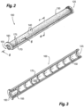
- FIGS. 2-5 Details of a representative one of the diffuser assemblies 100 are provided by FIGS. 2-5 .
- FIGS. 2 and 3 show top and bottom perspective views, respectively, while FIGS. 4 and 5 show sectional views along the cleave planes indicated in FIG. 2 .
- the representative diffuser assembly 100 comprises a diffuser body 125 and a flexible diffuser membrane 130.
- the diffuser body 125 and the flexible diffuser membrane 130 do not describe complete cylinders in the manner of a conventional tube diffuser. Rather, the present diffuser body 125 and the overlying flexible diffuser membrane 130 describe half of a cylinder.
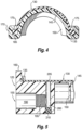
- the cross-sections of the diffuser body 125 and the overlying flexible diffuser membrane 130 in a cleave plane perpendicular to the diffuser membrane's longitudinal axis ( FIG. 4 ) approximate 180-degree arcs with curvatures transverse to the longitudinal axes of the diffuser body 125 and the flexible diffuser membrane 130.
- the flexible diffuser membrane 130 Viewed top down in elevation (i.e., in plan view), the flexible diffuser membrane 130 is rectangular with four straight edges and defines a perimeter edge bead 135 running about these four edges.
- the perimeter edge bead 135 approximates a square in cross-section with rounded corners ( FIG. 4 ).
- a plurality of perforations 140 penetrate the flexible diffuser membrane 130 to allow air bubbles to escape into the surrounding wastewater 120.
- the diffuser body 125 defines an arc-shaped underlying body portion 145 that underlies the flexible diffuser membrane 130. Transverse reinforcing members 150 underlie the arc-shaped underlying body portion145 to add rigidity thereto. A receiving portion 155 and an arc-shaped tab 160 are found at a proximate end of the diffuser body 125.
- the diffuser body 125 further defines a perimeter edge frame 170 that runs about a perimeter of the diffuser body 125.
- the perimeter edge frame 170 is integral to the diffuser body 125, meaning that the perimeter edge frame 170 cannot be removed from the arc-shaped underlying body portion 145 and the remainder of the diffuser body 125 without cutting, breaking, melting, or otherwise damaging the diffuser body 125.
- the perimeter edge frame 170 of the diffuser body 125 covers a portion of the perimeter edge bead 135 of the flexible diffuser membrane 130 (hereinafter the "covered portion of the perimeter edge bead 135") to retain the flexible diffuser membrane 130 to the diffuser body 125 and to create an airtight seal therebetween.
- the perimeter edge frame 170 defines a plurality of slots 175 therein, each slot 175 exposing a respective outside surface portion of the perimeter edge bead 135.
- the perimeter edge frame 170 defines an inside surface 185 that conforms to an outside shape of the covered portion of the perimeter edge bead 135 without substantially compressing the perimeter edge bead 135 ( FIG. 4 ).
- the receiving portion 155 at the proximate end of the diffuser body 125 aids in coupling the flexible diffuser membrane 130 to its source of compressed air, and ultimately routing that air to a position between the flexible diffuser membrane 130 and the arc-shaped underlying body portion 145 that immediately underlies the flexible diffuser membrane 130.
- FIG. 5 provides details of the internal components of the diffuser body 125 in the vicinity of the receiving portion 155.
- the receiving portion 155 defines a hollow-cylindrical straight-walled sub-portion 190 that terminates in a hollow-cylindrical internally-threaded sub-portion 195.
- an internal vertical tube 200 is in gaseous communication with the hollow-cylindrical straight-walled sub-portion 190 and the hollow-cylindrical internally-threaded sub-portion 195.
- the internal vertical tube 200 terminates in an opening 205 in the diffuser body 125 that sits immediately below (i.e., underlies) a region of the flexible diffuser membrane 130.
- a plug 210 at the bottom of the internal vertical tube 200 stops air from being released from the bottom of the internal vertical tube 200. Pressurized air entering the internal vertical tube 200 through the receiving portion 155 is thereby forced into the region between the flexible diffuser membrane 130 and the arc-shaped underlying body portion 145. That air is ultimately released through the perforations 140 in the flexible diffuser membrane 130.
- the flexible diffuser membrane 130 may comprise an elastomer such as, but not limited to, ethylene propylene diene monomer (EPDM).
- EPDM ethylene propylene diene monomer
- One or both sides of the flexible diffuser membrane 130 may be covered in a fluoroelastomer such as, for example, polytetrafluoroethylene (PTFE), or the flexible diffuser membrane 130 may be impregnated with fluorine. Both PTFE coatings and fluorine impregnation have been demonstrated to reduce the rate at which diffuser membranes are fouled.
- the diffuser body 125 may comprise a plastic such as but not limited to, for example, polypropylene, acrylonitrile butadiene styrene, polyvinyl chloride, and polyoxymethylene.
- the integral nature of the diffuser body 125 and the flexible diffuser membrane 130 in the diffuser assembly 100 may be facilitated by injection molding the diffuser body 125 around the flexible diffuser membrane 130 utilizing several molding parts. This may be described as a form of "co-molding.” General aspects of injection molding will already be familiar to one having ordinary skill in the relevant arts, and are also described in several readily accessible publications including, as just one example, D.V. Rosatto et al., Injection Molding Handbook (Springer Science & Business Media, 2012 ).
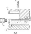
- FIG. 6 An exploded sectional view of the molding parts in relation to the flexible diffuser membrane 130 prior to thermoplastic injection is shown in FIG. 6
- FIG. 7 a sectional view of the same molding parts arranged about the flexible diffuser membrane after thermoplastic injection (i.e., after formation of the diffuser body 125) is shown in FIG. 7 .
- FIGS. 8-11 show sectional views of molding parts in relation to the perimeter edge bead 135 of the flexible diffuser membrane 130, with FIGS. 8 and 9 being before thermoplastic injection, and FIGS. 10 and 11 being after.
- the molding parts include a top mold 215, a bottom mold 220, a receiving portion insert 225, and an internal vertical tube insert 230.
- the injection molding set forth in FIGS. 6-11 is performed with the flexible diffuser membrane 130 upside-down (and ultimately the diffuser body 125 upside-down) in relation to its orientation in the previous figures.
- the receiving portion insert 225 defines the space that will ultimately become the receiving portion 155 of the diffuser assembly 100
- the internal vertical tube insert 230 defines the space that will ultimately become the internal vertical tube 200 and the volume occupied by the plug 210 in the diffuser assembly 100.
- the flexible diffuser membrane 130 Prior and during injection molding, the flexible diffuser membrane 130 is supported upside-down along its perimeter edge bead 135 by a set of supporting teeth 235 defined by the bottom mold 220.
- molten thermoplastic directly contacts the covered portion of the perimeter edge bead 135.
- FIGS. 8 and 10 show a region where a supporting tooth 235 is present in the bottom mold 220, while FIGS. 9 and 11 show a region without a supporting tooth 235. From these views, it becomes clear that, where the supporting teeth 235 are present, one obtains the slots 175 in the perimeter edge frame 170 of the diffuser body 125 that are so apparent in FIGS. 1 , 2 , and 4 , thereby explaining the source of these slots 175.
- the fully encompassing regions of the perimeter edge frame 170 are present. Because the molten thermoplastic is able to flow directly against the perimeter edge bead 135 of the flexible diffuser membrane 130, one also finds that the perimeter edge frame 170 defines the inside surface 185 that conforms to an outside shape of the covered portion of the perimeter edge bead 135. The molten thermoplastic does not tend to compress the perimeter edge bead 135 to any great extent.
- the covered portion of the perimeter edge bead 135 consists of a majority of the perimeter edge bead 135.
- a thin sheet may be disposed prior to molding between the diffuser membrane 130 and the volume that will ultimately become the arc-shaped underlying body portion 145.
- the thin sheet may comprise a plastic; in a preferred embodiment, the thin sheet is formed of the same plastic as the diffuser body.
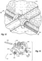
- FIGS. 12-15 describe the use of the connections saddle 110 to make the connections.
- FIG. 12 shows a perspective view of two diffuser assemblies 100, the connection saddle 110, and the gas distribution pipe 105 while in use
- FIG. 13 shows an exploded perspective view of the connection saddle 110 itself.
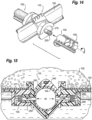
- FIG. 14 shows an exploded perspective view of the elements in FIG. 12
- FIG. 15 shows a sectional view of the elements in FIG. 12 along the cleave plane in FIG. 12 .
- connection saddle 110 is a clamshell device with two hinged halves 240 that come together around the gas distribution pipe 105. Once closed about the air-supply pipe, the two halves 240 are fixed together by a wedge 245 that passes through passages 250 in each of the halves ( FIG. 13 ). Two connection nipples 255, one on each half of the connection saddle 110, penetrate opposed openings in the gas distribution pipe 105. Rubber o-rings 260 assure a gastight seal between the connection nipples 255 and these openings.
- Each half 240 of the connection saddle 110 also defines are an arc-shaped receiving volume 265 that is sized to receive the arc-shaped tabs 160 on each of the diffuser assemblies 100. Connecting one of the diffuser assemblies 100 to the connection saddle 110 is therefore as easy as inserting one of the connection nipples 255 into the receiving portion 155 of the diffuser assembly 100 with the arc-shaped tab 160 facing away from the arc-shaped receiving volume 265, and then rotating the diffuser assembly 180-degrees so that the arc-shaped tab 160 seats inside the arc-shaped receiving volume 265 ( FIG. 14 ).
- connection nipples 255 Two additional o-rings 275 on each of the connection nipples 255 assures an airtight seal between the connection nipples 255 and the hollow-cylindrical straight-walled sub-portion 190 inside the receiving portion 155 of the diffuser assembly 100. Pressurized air provided by the gas distribution pipe 105 thereby is able to pass through the connection nipples 255, into the receiving portions 155 of the diffuser assemblies 100, and ultimately up the internal vertical tubes 200.
- the gas from the opening 205 expands the flexible diffuser membrane 130 away from the diffuser body 125 and causes the gas to discharge from the perforations 140 of the flexible diffuser membrane 130 as fine bubbles.
- an intact region 277 of the flexible diffuser membrane 130 which is devoid of perforations 140, may sit above the opening 205 created by the internal vertical tube 200 in the diffuser body 125. This intact region 277 allows the diffuser assembly 100 to act as a check valve and to prevent wastewater 120 from flooding the diffuser assembly 100 and the gas distribution pipe 105 when the pressurized gas is shut off.
- the flexible diffuser membrane 130 collapses back onto the diffuser body 125 both in response to the natural tendency of the flexible diffuser membrane 130 to return to a relaxed, un-stretched shape and in response to the weight of the surrounding wastewater 120. So relaxed, the intact region 277 of the flexible diffuser membrane 130 overlies the opening 205 and prevents wastewater 120 from entering the internal vertical tube 200 in the opposite direction.
- the above-described diffuser assembly 100 thereby becomes a one-piece, "solid-state" diffuser assembly, meaning that it does not utilize other elements (e.g., clamps) to attach the flexible diffuser membrane 130 to the diffuser body 125.
- the diffuser assembly 100 may provide several advantages over conventional technologies.
- the diffuser assembly 100 may be utilized in the field as a disposable part.
- the entire diffuser assembly 100 may be replaced by a new one.
- Such a replacement is a simple operation, requiring only one new part, and, with that single part, the chance of leaks is substantially reduced.
- the fact that the diffuser body 125 and the flexible diffuser membrane 130 only describe portions of cylinders rather than complete cylinders in the manor of conventional tube diffusers also saves on materials and weight.
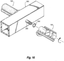
- FIG. 16 shows an exploded perspective view of diffuser assemblies 100 in association with a square gas distribution pipe 280.
- the square gas distribution pipe 280 defines a pair of threaded nipples 285. Once inserted into the receiving portions 155 of the diffuser assemblies 100, these threaded nipples 285 are able to threadably engage the hollow-cylindrical internally-threaded sub-portions 195 by rotating the diffuser assemblies 100. O-rings 290 ensure an airtight seal.
- a conventional flexible tube diffuser membrane is somewhat loose when applied to its underlying support tube. This looseness makes installation less difficult, improves the uniformity of the air distribution through the flexible diffuser membrane (particularly when air flow rates are low), and reduces the pressure drop associated with inflating and penetrating the flexible diffuser membrane (i.e., head loss). However, this looseness also frequently negatively impacts the useful lifetime of a flexible diffuser membrane.
- a common failure mechanism for flexible diffuser membranes in conventional tube diffusers is "flexure failures" or “destructive folding,” wherein buoyancy, wastewater velocity, and/or debris combine with the relatively loose fit of the flexible diffuser membrane to cause the flexible diffuser membrane to fold on itself (i.e., pinch) when the supply of pressurized air is turned off. With frequent on/off cycling of the pressurized air, as is common in, for example, Sequencing Batch Reactors (SBRs), this repeated folding ultimately causes the flexible diffuser membrane to tear.
- SBRs Sequencing Batch Reactors
- FIG. 17 shows a partially broken perspective view of a portion of a first alternative diffuser assembly 295 in accordance with an alternative illustrative embodiment of the invention that addresses concerns about flexure failures.
- the first alternative diffuser assembly 295 includes many of the elements of the diffuser assembly 100, including a diffuser body 300 with an arc-shaped underlying body portion 305 that underlies a flexible diffuser membrane 310. However, instead of having a relatively smooth surface in the manner of the arc-shaped underlying body portion 145, the arc-shaped underlying body portion 305 in the first alternative diffuser assembly 295 defines a set of ridges 315 (or ripples) that underlie the flexible diffuser membrane 310.
- ridges 315 prevent the flexible diffuser membrane 310 from bunching up or pinching off, particularly when the supply of pressurized air to the first alternative diffuser assembly 295 is shut off. That is, the ridges 315 supply the flexible diffuser membrane 310 with a large, gently-shaped surface area onto which to relax when the pressurized gas is turned off. Flexure failures of the type described above are thereby avoided.
- FIGS. 18 and 19 show aspects of a second alternative diffuser assembly 320 in accordance with a second alternative embodiment of the invention.
- FIG. 19 shows a plan view while FIG. 20 shows a distal end elevational view.
- the second alternative diffuser assembly 320 includes a diffuser body 325 with a perimeter edge frame along four edges, and a flexible diffuser membrane 330 with a perimeter edge bead along four edges.
- the diffuser body 325 underlying the flexible diffuser membrane 330 is flat.
- the second alternative diffuser assembly 320 functions in a manner similar to the diffuser assembly 100, and may be formed by injection molding in a comparable manner.
Landscapes
- Chemical & Material Sciences (AREA)
- Chemical Kinetics & Catalysis (AREA)
- Life Sciences & Earth Sciences (AREA)
- Biodiversity & Conservation Biology (AREA)
- Microbiology (AREA)
- Hydrology & Water Resources (AREA)
- Engineering & Computer Science (AREA)
- Environmental & Geological Engineering (AREA)
- Water Supply & Treatment (AREA)
- Organic Chemistry (AREA)
- Separation Using Semi-Permeable Membranes (AREA)
- Structures Of Non-Positive Displacement Pumps (AREA)
Claims (5)
- Diffusoranordnung (100), umfassend:eine flexible Diffusormembran (130), die einen Umfangsrandwulst (135) entlang vier Kanten definiert, wobei die flexible Diffusormembran in der Draufsicht rechteckig ist;einen Diffusorkörper (125), der definiert:einen darunterliegenden Körperabschnitt (145), der unter der flexiblen Diffusormembran liegt;einen Umfangsrandrahmen (170), der einen abgedeckten Abschnitt des Umfangsrandwulstes so abdeckt, dass die flexible Diffusormembran am Diffusorkörper gehalten wird und dazwischen eine luftdichte Abdichtung entsteht;eine Öffnung (205), die unter einem Bereich der flexiblen Diffusormembran liegt;wobei der Umfangsrandrahmen eine Innenfläche (185) definiert, die einer Außenform des abgedeckten Abschnitts des Umfangsrandwulstes entspricht;wobei der Umfangsrandrahmen einstückig mit dem darunterliegenden Körperabschnitt ausgebildet ist;dadurch gekennzeichnet, dass der Diffusorkörper ferner definiert:
einen Aufnahmeabschnitt (155) an einem proximalen Ende des Diffusorkörpers, der definiert:einen hohlzylindrischen Unterabschnitt (190) mit gerader Wand; undeinen hohlzylindrischen Unterabschnitt (195) mit Innengewinde an einem Ende des hohlzylindrischen Unterabschnitts mit gerader Wand;ein inneres vertikales Rohr (200), das in Gasverbindung mit dem hohlzylindrischen Unterabschnitt mit gerader Wand und dem hohlzylindrischen Unterabschnitt mit Innengewinde steht und quer zu diesen Unterabschnitten verläuft, wobei das innere vertikale Rohr in der Öffnung endet, so dass der hohlzylindrische Unterabschnitt mit gerader Wand und der hohlzylindrische Unterabschnitt mit Innengewinde in Gasverbindung mit der Öffnung stehen; undeinen Stopfen (210) an einem Boden des inneren vertikalen Rohrs gegenüber der Öffnung;wobei der Umfangsrandrahmen eine Vielzahl von Schlitzen (175) darin definiert, wobei jeder der Vielzahl von Schlitzen einen jeweiligen äußeren Oberflächenabschnitt des Umfangsrandwulstes freigibt; undwobei der darunterliegende Körperabschnitt einen Bogen mit einer Krümmung quer zu einer Längsachse des darunterliegenden Körperabschnitts definiert. - Difussoranordnung (100) nach Anspruch 1, wobei:die flexible Diffusormembran (130) ein Elastomer umfasst;die flexible Diffusormembran eine Vielzahl von Perforationen (140) durch diese hindurch definiert, undder Diffusorkörper (125) einen thermoplastischen Kunststoff umfasst.
- Diffusoranordnung (100) nach einem der vorhergehenden Ansprüche, wobei der Umfangsrandwulst (135) durch den Diffusorkörper (125) nicht wesentlich komprimiert wird, so dass ein Volumen des Umfangsrandwulstes durch Kompression um nicht mehr als zehn Prozent reduziert wird.
- Diffusoranordnung (100) nach einem der vorhergehenden Ansprüche, wobei der abgedeckte Abschnitt des Umfangsrandwulstes (135) aus einem Großteil des Umfangsrandwulstes besteht.
- Abwasserbehandlungssystem (100, 105, 110, 115, 120), umfassend:einen Abwasserbehandlungsbehälter (115), der einen Boden definiert,ein über dem Boden gelagertes Gasverteilungsrohr (105); undeine Diffusoranordnung (100) nach Anspruch 1, die in Gasverbindung mit einer Innenseite des Gasverteilungsrohrs steht.
Applications Claiming Priority (1)
| Application Number | Priority Date | Filing Date | Title |
|---|---|---|---|
| US15/674,167 US10773982B2 (en) | 2017-08-10 | 2017-08-10 | Diffuser assembly |
Publications (3)
| Publication Number | Publication Date |
|---|---|
| EP3450002A2 EP3450002A2 (de) | 2019-03-06 |
| EP3450002A3 EP3450002A3 (de) | 2019-05-29 |
| EP3450002B1 true EP3450002B1 (de) | 2024-08-21 |
Family
ID=62916557
Family Applications (1)
| Application Number | Title | Priority Date | Filing Date |
|---|---|---|---|
| EP18182951.6A Active EP3450002B1 (de) | 2017-08-10 | 2018-07-11 | Diffusoranordnung und herstellungsverfahren dafür |
Country Status (2)
| Country | Link |
|---|---|
| US (1) | US10773982B2 (de) |
| EP (1) | EP3450002B1 (de) |
Families Citing this family (1)
| Publication number | Priority date | Publication date | Assignee | Title |
|---|---|---|---|---|
| US20250288961A1 (en) | 2024-03-16 | 2025-09-18 | Thomas E. Frankel | Diffuser assembly for use in wastewater treatment |
Citations (4)
| Publication number | Priority date | Publication date | Assignee | Title |
|---|---|---|---|---|
| WO2003043722A1 (en) * | 2001-11-23 | 2003-05-30 | Thomas Urie Lawson | Device for aerating liquids |
| WO2004014532A1 (en) * | 2002-08-13 | 2004-02-19 | Itt Manufacturing Enterprises, Inc. | Strip diffuser pct i |
| US20080251954A1 (en) * | 2002-08-13 | 2008-10-16 | Casper Thomas J | Strip diffuser |
| DE102012008800A1 (de) * | 2012-05-07 | 2013-11-07 | Arnold Jäger Holding GmbH | Streifenbelüfter |
Family Cites Families (7)
| Publication number | Priority date | Publication date | Assignee | Title |
|---|---|---|---|---|
| DE3918307A1 (de) * | 1989-06-05 | 1990-12-13 | Roediger Ag | Flaechenbegaser |
| US7311299B2 (en) * | 2004-10-26 | 2007-12-25 | Daicen Membrane-Systems, Ltd. | Aeration device and aeration system |
| US8061689B2 (en) * | 2007-12-31 | 2011-11-22 | Environmental Dynamics, Inc. | Disk diffuser with improved seal |
| AT506717A1 (de) * | 2008-05-02 | 2009-11-15 | Aquaconsult Anlagenbau Gmbh | Vorrichtung zum eintragen von gasbläschen in eine flüssigkeit |
| US8371561B2 (en) * | 2010-04-12 | 2013-02-12 | Xylem Ip Holdings Llc | Aeration diffuser assembly end seal |
| KR101291238B1 (ko) | 2010-11-11 | 2013-08-01 | 주식회사 그린기술산업 | 역류방지 기능이 구비된 멤브레인 산기관 |
| US10633267B2 (en) | 2016-01-27 | 2020-04-28 | Thomas E. Frankel | Fine bubble diffuser assembly |
-
2017
- 2017-08-10 US US15/674,167 patent/US10773982B2/en active Active
-
2018
- 2018-07-11 EP EP18182951.6A patent/EP3450002B1/de active Active
Patent Citations (4)
| Publication number | Priority date | Publication date | Assignee | Title |
|---|---|---|---|---|
| WO2003043722A1 (en) * | 2001-11-23 | 2003-05-30 | Thomas Urie Lawson | Device for aerating liquids |
| WO2004014532A1 (en) * | 2002-08-13 | 2004-02-19 | Itt Manufacturing Enterprises, Inc. | Strip diffuser pct i |
| US20080251954A1 (en) * | 2002-08-13 | 2008-10-16 | Casper Thomas J | Strip diffuser |
| DE102012008800A1 (de) * | 2012-05-07 | 2013-11-07 | Arnold Jäger Holding GmbH | Streifenbelüfter |
Also Published As
| Publication number | Publication date |
|---|---|
| EP3450002A3 (de) | 2019-05-29 |
| EP3450002A2 (de) | 2019-03-06 |
| US20190047887A1 (en) | 2019-02-14 |
| US10773982B2 (en) | 2020-09-15 |
Similar Documents
| Publication | Publication Date | Title |
|---|---|---|
| US5788847A (en) | Diffuser construction and mounting arrangement | |
| CN1321728C (zh) | 带状扩散器pct i | |
| KR102348718B1 (ko) | 액체의 가스화를 위한 폭기 요소 | |
| JP4846339B2 (ja) | 散気装置および散気システム | |
| JP7675639B2 (ja) | メンブレン式散気装置 | |
| JP2017526871A (ja) | エアレーション部材用アセンブリーブラケットおよび取り付けシステム | |
| EP3207979B1 (de) | Feinblasige diffusoranordnung und herstellungsverfahren | |
| EP3450002B1 (de) | Diffusoranordnung und herstellungsverfahren dafür | |
| US20070013089A1 (en) | Aeration device and aeration system | |
| JP5349370B2 (ja) | 散気管および散気装置 | |
| JP4428650B2 (ja) | 散気用弾性多孔体及び散気装置 | |
| KR102387215B1 (ko) | 멤브레인 교체식 판형 산기장치 | |
| JP3175355U (ja) | 散気装置 | |
| US8657268B2 (en) | Methods and apparatus for wastewater treatment | |
| CN113060798B (zh) | 可更换过滤膜组件的罐型过滤设备 | |
| CN205933365U (zh) | 扩散器组件及包括该组件的废水处理槽 | |
| US7141203B2 (en) | Method of making a diffuser assembly | |
| JP2002013651A (ja) | 散気装置用逆流防止弁 | |
| KR20190088617A (ko) | 디퓨저 어셈블리 및 상기 디퓨저 어셈블리를 포함하는 폐수 처리 시스템 | |
| US6889964B2 (en) | Diffuser | |
| EP3040113B1 (de) | Anordnung zur aufbereitung von abwasser | |
| JP7561601B2 (ja) | メンブレン式散気装置および散気設備 | |
| JPH022865A (ja) | 液体通気装置 | |
| JP2022097833A (ja) | メンブレン式散気装置、散気設備およびメンブレンの製造方法 | |
| JP7675640B2 (ja) | メンブレン式散気装置 |
Legal Events
| Date | Code | Title | Description |
|---|---|---|---|
| PUAI | Public reference made under article 153(3) epc to a published international application that has entered the european phase |
Free format text: ORIGINAL CODE: 0009012 |
|
| STAA | Information on the status of an ep patent application or granted ep patent |
Free format text: STATUS: THE APPLICATION HAS BEEN PUBLISHED |
|
| AK | Designated contracting states |
Kind code of ref document: A2 Designated state(s): AL AT BE BG CH CY CZ DE DK EE ES FI FR GB GR HR HU IE IS IT LI LT LU LV MC MK MT NL NO PL PT RO RS SE SI SK SM TR |
|
| AX | Request for extension of the european patent |
Extension state: BA ME |
|
| PUAL | Search report despatched |
Free format text: ORIGINAL CODE: 0009013 |
|
| AK | Designated contracting states |
Kind code of ref document: A3 Designated state(s): AL AT BE BG CH CY CZ DE DK EE ES FI FR GB GR HR HU IE IS IT LI LT LU LV MC MK MT NL NO PL PT RO RS SE SI SK SM TR |
|
| AX | Request for extension of the european patent |
Extension state: BA ME |
|
| RIC1 | Information provided on ipc code assigned before grant |
Ipc: B01F 3/04 20060101AFI20190425BHEP |
|
| STAA | Information on the status of an ep patent application or granted ep patent |
Free format text: STATUS: REQUEST FOR EXAMINATION WAS MADE |
|
| 17P | Request for examination filed |
Effective date: 20191125 |
|
| RBV | Designated contracting states (corrected) |
Designated state(s): AL AT BE BG CH CY CZ DE DK EE ES FI FR GB GR HR HU IE IS IT LI LT LU LV MC MK MT NL NO PL PT RO RS SE SI SK SM TR |
|
| STAA | Information on the status of an ep patent application or granted ep patent |
Free format text: STATUS: EXAMINATION IS IN PROGRESS |
|
| 17Q | First examination report despatched |
Effective date: 20200605 |
|
| REG | Reference to a national code |
Ref country code: DE Ref legal event code: R079 Free format text: PREVIOUS MAIN CLASS: B01F0003040000 Ipc: B01F0023231000 Ref country code: DE Ref legal event code: R079 Ref document number: 602018073291 Country of ref document: DE Free format text: PREVIOUS MAIN CLASS: B01F0003040000 Ipc: B01F0023231000 |
|
| GRAP | Despatch of communication of intention to grant a patent |
Free format text: ORIGINAL CODE: EPIDOSNIGR1 |
|
| STAA | Information on the status of an ep patent application or granted ep patent |
Free format text: STATUS: GRANT OF PATENT IS INTENDED |
|
| RIC1 | Information provided on ipc code assigned before grant |
Ipc: C02F 3/20 20060101ALI20240220BHEP Ipc: B01F 23/231 20220101AFI20240220BHEP |
|
| INTG | Intention to grant announced |
Effective date: 20240318 |
|
| GRAS | Grant fee paid |
Free format text: ORIGINAL CODE: EPIDOSNIGR3 |
|
| GRAA | (expected) grant |
Free format text: ORIGINAL CODE: 0009210 |
|
| STAA | Information on the status of an ep patent application or granted ep patent |
Free format text: STATUS: THE PATENT HAS BEEN GRANTED |
|
| AK | Designated contracting states |
Kind code of ref document: B1 Designated state(s): AL AT BE BG CH CY CZ DE DK EE ES FI FR GB GR HR HU IE IS IT LI LT LU LV MC MK MT NL NO PL PT RO RS SE SI SK SM TR |
|
| REG | Reference to a national code |
Ref country code: GB Ref legal event code: FG4D |
|
| REG | Reference to a national code |
Ref country code: CH Ref legal event code: EP |
|
| REG | Reference to a national code |
Ref country code: IE Ref legal event code: FG4D |
|
| REG | Reference to a national code |
Ref country code: DE Ref legal event code: R096 Ref document number: 602018073291 Country of ref document: DE |
|
| REG | Reference to a national code |
Ref country code: LT Ref legal event code: MG9D |
|
| REG | Reference to a national code |
Ref country code: NL Ref legal event code: MP Effective date: 20240821 |
|
| PG25 | Lapsed in a contracting state [announced via postgrant information from national office to epo] |
Ref country code: NO Free format text: LAPSE BECAUSE OF FAILURE TO SUBMIT A TRANSLATION OF THE DESCRIPTION OR TO PAY THE FEE WITHIN THE PRESCRIBED TIME-LIMIT Effective date: 20241121 |
|
| REG | Reference to a national code |
Ref country code: AT Ref legal event code: MK05 Ref document number: 1715009 Country of ref document: AT Kind code of ref document: T Effective date: 20240821 |
|
| PG25 | Lapsed in a contracting state [announced via postgrant information from national office to epo] |
Ref country code: FI Free format text: LAPSE BECAUSE OF FAILURE TO SUBMIT A TRANSLATION OF THE DESCRIPTION OR TO PAY THE FEE WITHIN THE PRESCRIBED TIME-LIMIT Effective date: 20240821 Ref country code: PL Free format text: LAPSE BECAUSE OF FAILURE TO SUBMIT A TRANSLATION OF THE DESCRIPTION OR TO PAY THE FEE WITHIN THE PRESCRIBED TIME-LIMIT Effective date: 20240821 Ref country code: NL Free format text: LAPSE BECAUSE OF FAILURE TO SUBMIT A TRANSLATION OF THE DESCRIPTION OR TO PAY THE FEE WITHIN THE PRESCRIBED TIME-LIMIT Effective date: 20240821 Ref country code: PT Free format text: LAPSE BECAUSE OF FAILURE TO SUBMIT A TRANSLATION OF THE DESCRIPTION OR TO PAY THE FEE WITHIN THE PRESCRIBED TIME-LIMIT Effective date: 20241223 Ref country code: GR Free format text: LAPSE BECAUSE OF FAILURE TO SUBMIT A TRANSLATION OF THE DESCRIPTION OR TO PAY THE FEE WITHIN THE PRESCRIBED TIME-LIMIT Effective date: 20241122 |
|
| PG25 | Lapsed in a contracting state [announced via postgrant information from national office to epo] |
Ref country code: BG Free format text: LAPSE BECAUSE OF FAILURE TO SUBMIT A TRANSLATION OF THE DESCRIPTION OR TO PAY THE FEE WITHIN THE PRESCRIBED TIME-LIMIT Effective date: 20240821 |
|
| PG25 | Lapsed in a contracting state [announced via postgrant information from national office to epo] |
Ref country code: LV Free format text: LAPSE BECAUSE OF FAILURE TO SUBMIT A TRANSLATION OF THE DESCRIPTION OR TO PAY THE FEE WITHIN THE PRESCRIBED TIME-LIMIT Effective date: 20240821 |
|
| PG25 | Lapsed in a contracting state [announced via postgrant information from national office to epo] |
Ref country code: IS Free format text: LAPSE BECAUSE OF FAILURE TO SUBMIT A TRANSLATION OF THE DESCRIPTION OR TO PAY THE FEE WITHIN THE PRESCRIBED TIME-LIMIT Effective date: 20241221 Ref country code: AT Free format text: LAPSE BECAUSE OF FAILURE TO SUBMIT A TRANSLATION OF THE DESCRIPTION OR TO PAY THE FEE WITHIN THE PRESCRIBED TIME-LIMIT Effective date: 20240821 |
|
| PG25 | Lapsed in a contracting state [announced via postgrant information from national office to epo] |
Ref country code: HR Free format text: LAPSE BECAUSE OF FAILURE TO SUBMIT A TRANSLATION OF THE DESCRIPTION OR TO PAY THE FEE WITHIN THE PRESCRIBED TIME-LIMIT Effective date: 20240821 |
|
| PG25 | Lapsed in a contracting state [announced via postgrant information from national office to epo] |
Ref country code: ES Free format text: LAPSE BECAUSE OF FAILURE TO SUBMIT A TRANSLATION OF THE DESCRIPTION OR TO PAY THE FEE WITHIN THE PRESCRIBED TIME-LIMIT Effective date: 20240821 Ref country code: RS Free format text: LAPSE BECAUSE OF FAILURE TO SUBMIT A TRANSLATION OF THE DESCRIPTION OR TO PAY THE FEE WITHIN THE PRESCRIBED TIME-LIMIT Effective date: 20241121 |
|
| PG25 | Lapsed in a contracting state [announced via postgrant information from national office to epo] |
Ref country code: RS Free format text: LAPSE BECAUSE OF FAILURE TO SUBMIT A TRANSLATION OF THE DESCRIPTION OR TO PAY THE FEE WITHIN THE PRESCRIBED TIME-LIMIT Effective date: 20241121 Ref country code: PT Free format text: LAPSE BECAUSE OF FAILURE TO SUBMIT A TRANSLATION OF THE DESCRIPTION OR TO PAY THE FEE WITHIN THE PRESCRIBED TIME-LIMIT Effective date: 20241223 Ref country code: PL Free format text: LAPSE BECAUSE OF FAILURE TO SUBMIT A TRANSLATION OF THE DESCRIPTION OR TO PAY THE FEE WITHIN THE PRESCRIBED TIME-LIMIT Effective date: 20240821 Ref country code: NO Free format text: LAPSE BECAUSE OF FAILURE TO SUBMIT A TRANSLATION OF THE DESCRIPTION OR TO PAY THE FEE WITHIN THE PRESCRIBED TIME-LIMIT Effective date: 20241121 Ref country code: NL Free format text: LAPSE BECAUSE OF FAILURE TO SUBMIT A TRANSLATION OF THE DESCRIPTION OR TO PAY THE FEE WITHIN THE PRESCRIBED TIME-LIMIT Effective date: 20240821 Ref country code: LV Free format text: LAPSE BECAUSE OF FAILURE TO SUBMIT A TRANSLATION OF THE DESCRIPTION OR TO PAY THE FEE WITHIN THE PRESCRIBED TIME-LIMIT Effective date: 20240821 Ref country code: IS Free format text: LAPSE BECAUSE OF FAILURE TO SUBMIT A TRANSLATION OF THE DESCRIPTION OR TO PAY THE FEE WITHIN THE PRESCRIBED TIME-LIMIT Effective date: 20241221 Ref country code: HR Free format text: LAPSE BECAUSE OF FAILURE TO SUBMIT A TRANSLATION OF THE DESCRIPTION OR TO PAY THE FEE WITHIN THE PRESCRIBED TIME-LIMIT Effective date: 20240821 Ref country code: GR Free format text: LAPSE BECAUSE OF FAILURE TO SUBMIT A TRANSLATION OF THE DESCRIPTION OR TO PAY THE FEE WITHIN THE PRESCRIBED TIME-LIMIT Effective date: 20241122 Ref country code: FI Free format text: LAPSE BECAUSE OF FAILURE TO SUBMIT A TRANSLATION OF THE DESCRIPTION OR TO PAY THE FEE WITHIN THE PRESCRIBED TIME-LIMIT Effective date: 20240821 Ref country code: ES Free format text: LAPSE BECAUSE OF FAILURE TO SUBMIT A TRANSLATION OF THE DESCRIPTION OR TO PAY THE FEE WITHIN THE PRESCRIBED TIME-LIMIT Effective date: 20240821 Ref country code: BG Free format text: LAPSE BECAUSE OF FAILURE TO SUBMIT A TRANSLATION OF THE DESCRIPTION OR TO PAY THE FEE WITHIN THE PRESCRIBED TIME-LIMIT Effective date: 20240821 Ref country code: AT Free format text: LAPSE BECAUSE OF FAILURE TO SUBMIT A TRANSLATION OF THE DESCRIPTION OR TO PAY THE FEE WITHIN THE PRESCRIBED TIME-LIMIT Effective date: 20240821 |
|
| PG25 | Lapsed in a contracting state [announced via postgrant information from national office to epo] |
Ref country code: DK Free format text: LAPSE BECAUSE OF FAILURE TO SUBMIT A TRANSLATION OF THE DESCRIPTION OR TO PAY THE FEE WITHIN THE PRESCRIBED TIME-LIMIT Effective date: 20240821 Ref country code: SM Free format text: LAPSE BECAUSE OF FAILURE TO SUBMIT A TRANSLATION OF THE DESCRIPTION OR TO PAY THE FEE WITHIN THE PRESCRIBED TIME-LIMIT Effective date: 20240821 Ref country code: RO Free format text: LAPSE BECAUSE OF FAILURE TO SUBMIT A TRANSLATION OF THE DESCRIPTION OR TO PAY THE FEE WITHIN THE PRESCRIBED TIME-LIMIT Effective date: 20240821 |
|
| PG25 | Lapsed in a contracting state [announced via postgrant information from national office to epo] |
Ref country code: EE Free format text: LAPSE BECAUSE OF FAILURE TO SUBMIT A TRANSLATION OF THE DESCRIPTION OR TO PAY THE FEE WITHIN THE PRESCRIBED TIME-LIMIT Effective date: 20240821 |
|
| PG25 | Lapsed in a contracting state [announced via postgrant information from national office to epo] |
Ref country code: CZ Free format text: LAPSE BECAUSE OF FAILURE TO SUBMIT A TRANSLATION OF THE DESCRIPTION OR TO PAY THE FEE WITHIN THE PRESCRIBED TIME-LIMIT Effective date: 20240821 |
|
| PG25 | Lapsed in a contracting state [announced via postgrant information from national office to epo] |
Ref country code: SK Free format text: LAPSE BECAUSE OF FAILURE TO SUBMIT A TRANSLATION OF THE DESCRIPTION OR TO PAY THE FEE WITHIN THE PRESCRIBED TIME-LIMIT Effective date: 20240821 |
|
| REG | Reference to a national code |
Ref country code: DE Ref legal event code: R097 Ref document number: 602018073291 Country of ref document: DE |
|
| REG | Reference to a national code |
Ref country code: GB Ref legal event code: 732E Free format text: REGISTERED BETWEEN 20250515 AND 20250521 |
|
| REG | Reference to a national code |
Ref country code: DE Ref legal event code: R082 Ref document number: 602018073291 Country of ref document: DE Representative=s name: MURGITROYD GERMANY PATENTANWALTSGESELLSCHAFT M, DE Ref country code: DE Ref legal event code: R081 Ref document number: 602018073291 Country of ref document: DE Owner name: SSI AERATION, INC., POUGHKEEPSIE, US Free format text: FORMER OWNERS: FRANKEL, THOMAS EDWARD, POUGHKEEPSIE, NY, US; KANG, SEOUNGIL, POUGHKEEPSIE, NY, US; RITTER, TODD DAVID, POUGHKEEPSIE, NY, US |
|
| PLBE | No opposition filed within time limit |
Free format text: ORIGINAL CODE: 0009261 |
|
| STAA | Information on the status of an ep patent application or granted ep patent |
Free format text: STATUS: NO OPPOSITION FILED WITHIN TIME LIMIT |
|
| 26N | No opposition filed |
Effective date: 20250522 |
|
| PG25 | Lapsed in a contracting state [announced via postgrant information from national office to epo] |
Ref country code: SE Free format text: LAPSE BECAUSE OF FAILURE TO SUBMIT A TRANSLATION OF THE DESCRIPTION OR TO PAY THE FEE WITHIN THE PRESCRIBED TIME-LIMIT Effective date: 20240821 |
|
| PGFP | Annual fee paid to national office [announced via postgrant information from national office to epo] |
Ref country code: DE Payment date: 20250730 Year of fee payment: 8 |
|
| PGFP | Annual fee paid to national office [announced via postgrant information from national office to epo] |
Ref country code: IT Payment date: 20250723 Year of fee payment: 8 |
|
| PGFP | Annual fee paid to national office [announced via postgrant information from national office to epo] |
Ref country code: GB Payment date: 20250730 Year of fee payment: 8 |
|
| PGFP | Annual fee paid to national office [announced via postgrant information from national office to epo] |
Ref country code: FR Payment date: 20250724 Year of fee payment: 8 |
|
| REG | Reference to a national code |
Ref country code: CH Ref legal event code: H13 Free format text: ST27 STATUS EVENT CODE: U-0-0-H10-H13 (AS PROVIDED BY THE NATIONAL OFFICE) Effective date: 20260224 |
|
| PG25 | Lapsed in a contracting state [announced via postgrant information from national office to epo] |
Ref country code: LU Free format text: LAPSE BECAUSE OF NON-PAYMENT OF DUE FEES Effective date: 20250711 |