EP3449876A1 - Verbesserte knöchelprothese - Google Patents
Verbesserte knöchelprothese Download PDFInfo
- Publication number
- EP3449876A1 EP3449876A1 EP18192345.9A EP18192345A EP3449876A1 EP 3449876 A1 EP3449876 A1 EP 3449876A1 EP 18192345 A EP18192345 A EP 18192345A EP 3449876 A1 EP3449876 A1 EP 3449876A1
- Authority
- EP
- European Patent Office
- Prior art keywords
- talar
- tibial
- component
- prosthesis
- medial
- Prior art date
- Legal status (The legal status is an assumption and is not a legal conclusion. Google has not performed a legal analysis and makes no representation as to the accuracy of the status listed.)
- Granted
Links
- 210000003423 ankle Anatomy 0.000 title claims abstract description 25
- 230000000295 complement effect Effects 0.000 claims description 15
- 210000002683 foot Anatomy 0.000 description 17
- 210000002303 tibia Anatomy 0.000 description 14
- 210000000988 bone and bone Anatomy 0.000 description 13
- 238000004873 anchoring Methods 0.000 description 12
- 210000004233 talus Anatomy 0.000 description 10
- 239000000463 material Substances 0.000 description 6
- 208000037873 arthrodesis Diseases 0.000 description 5
- 230000033001 locomotion Effects 0.000 description 5
- 210000002414 leg Anatomy 0.000 description 3
- RTAQQCXQSZGOHL-UHFFFAOYSA-N Titanium Chemical compound [Ti] RTAQQCXQSZGOHL-UHFFFAOYSA-N 0.000 description 2
- 210000000544 articulatio talocruralis Anatomy 0.000 description 2
- 239000011248 coating agent Substances 0.000 description 2
- 238000000576 coating method Methods 0.000 description 2
- 230000000694 effects Effects 0.000 description 2
- 230000005489 elastic deformation Effects 0.000 description 2
- 229920001903 high density polyethylene Polymers 0.000 description 2
- 239000004700 high-density polyethylene Substances 0.000 description 2
- 238000004519 manufacturing process Methods 0.000 description 2
- 230000007935 neutral effect Effects 0.000 description 2
- 239000004033 plastic Substances 0.000 description 2
- 229920003023 plastic Polymers 0.000 description 2
- 238000002360 preparation method Methods 0.000 description 2
- 238000011084 recovery Methods 0.000 description 2
- 229910052719 titanium Inorganic materials 0.000 description 2
- 239000010936 titanium Substances 0.000 description 2
- 208000006820 Arthralgia Diseases 0.000 description 1
- 208000020084 Bone disease Diseases 0.000 description 1
- 238000002679 ablation Methods 0.000 description 1
- 230000009471 action Effects 0.000 description 1
- 230000006978 adaptation Effects 0.000 description 1
- 229910045601 alloy Inorganic materials 0.000 description 1
- 239000000956 alloy Substances 0.000 description 1
- 238000011882 arthroplasty Methods 0.000 description 1
- 210000001188 articular cartilage Anatomy 0.000 description 1
- 230000015572 biosynthetic process Effects 0.000 description 1
- 230000000903 blocking effect Effects 0.000 description 1
- 238000005266 casting Methods 0.000 description 1
- 230000015556 catabolic process Effects 0.000 description 1
- 229910010293 ceramic material Inorganic materials 0.000 description 1
- IUWCPXJTIPQGTE-UHFFFAOYSA-N chromium cobalt Chemical compound [Cr].[Co].[Co].[Co] IUWCPXJTIPQGTE-UHFFFAOYSA-N 0.000 description 1
- 238000005520 cutting process Methods 0.000 description 1
- 208000031513 cyst Diseases 0.000 description 1
- 230000006378 damage Effects 0.000 description 1
- 230000003247 decreasing effect Effects 0.000 description 1
- 230000007547 defect Effects 0.000 description 1
- 230000007850 degeneration Effects 0.000 description 1
- 238000006731 degradation reaction Methods 0.000 description 1
- 230000006866 deterioration Effects 0.000 description 1
- 230000008034 disappearance Effects 0.000 description 1
- 238000005553 drilling Methods 0.000 description 1
- 238000000605 extraction Methods 0.000 description 1
- 230000036541 health Effects 0.000 description 1
- 229910052588 hydroxylapatite Inorganic materials 0.000 description 1
- 238000002347 injection Methods 0.000 description 1
- 239000007924 injection Substances 0.000 description 1
- 238000009434 installation Methods 0.000 description 1
- 230000003993 interaction Effects 0.000 description 1
- 230000007794 irritation Effects 0.000 description 1
- 210000001503 joint Anatomy 0.000 description 1
- 239000007769 metal material Substances 0.000 description 1
- 238000000034 method Methods 0.000 description 1
- 238000000465 moulding Methods 0.000 description 1
- 230000000399 orthopedic effect Effects 0.000 description 1
- 201000008482 osteoarthritis Diseases 0.000 description 1
- 230000007170 pathology Effects 0.000 description 1
- 230000035515 penetration Effects 0.000 description 1
- XYJRXVWERLGGKC-UHFFFAOYSA-D pentacalcium;hydroxide;triphosphate Chemical compound [OH-].[Ca+2].[Ca+2].[Ca+2].[Ca+2].[Ca+2].[O-]P([O-])([O-])=O.[O-]P([O-])([O-])=O.[O-]P([O-])([O-])=O XYJRXVWERLGGKC-UHFFFAOYSA-D 0.000 description 1
- 230000001737 promoting effect Effects 0.000 description 1
- 230000000284 resting effect Effects 0.000 description 1
- 230000002441 reversible effect Effects 0.000 description 1
- 238000005488 sandblasting Methods 0.000 description 1
- 238000010008 shearing Methods 0.000 description 1
- 238000005245 sintering Methods 0.000 description 1
- 210000004872 soft tissue Anatomy 0.000 description 1
- 239000010935 stainless steel Substances 0.000 description 1
- 229910001220 stainless steel Inorganic materials 0.000 description 1
- 230000001629 suppression Effects 0.000 description 1
- 238000001356 surgical procedure Methods 0.000 description 1
- 238000002560 therapeutic procedure Methods 0.000 description 1
- 230000007704 transition Effects 0.000 description 1
Images


Classifications
-
- A—HUMAN NECESSITIES
- A61—MEDICAL OR VETERINARY SCIENCE; HYGIENE
- A61F—FILTERS IMPLANTABLE INTO BLOOD VESSELS; PROSTHESES; DEVICES PROVIDING PATENCY TO, OR PREVENTING COLLAPSING OF, TUBULAR STRUCTURES OF THE BODY, e.g. STENTS; ORTHOPAEDIC, NURSING OR CONTRACEPTIVE DEVICES; FOMENTATION; TREATMENT OR PROTECTION OF EYES OR EARS; BANDAGES, DRESSINGS OR ABSORBENT PADS; FIRST-AID KITS
- A61F2/00—Filters implantable into blood vessels; Prostheses, i.e. artificial substitutes or replacements for parts of the body; Appliances for connecting them with the body; Devices providing patency to, or preventing collapsing of, tubular structures of the body, e.g. stents
- A61F2/02—Prostheses implantable into the body
- A61F2/30—Joints
- A61F2/42—Joints for wrists or ankles; for hands, e.g. fingers; for feet, e.g. toes
- A61F2/4202—Joints for wrists or ankles; for hands, e.g. fingers; for feet, e.g. toes for ankles
-
- A—HUMAN NECESSITIES
- A61—MEDICAL OR VETERINARY SCIENCE; HYGIENE
- A61F—FILTERS IMPLANTABLE INTO BLOOD VESSELS; PROSTHESES; DEVICES PROVIDING PATENCY TO, OR PREVENTING COLLAPSING OF, TUBULAR STRUCTURES OF THE BODY, e.g. STENTS; ORTHOPAEDIC, NURSING OR CONTRACEPTIVE DEVICES; FOMENTATION; TREATMENT OR PROTECTION OF EYES OR EARS; BANDAGES, DRESSINGS OR ABSORBENT PADS; FIRST-AID KITS
- A61F2/00—Filters implantable into blood vessels; Prostheses, i.e. artificial substitutes or replacements for parts of the body; Appliances for connecting them with the body; Devices providing patency to, or preventing collapsing of, tubular structures of the body, e.g. stents
- A61F2/02—Prostheses implantable into the body
- A61F2/30—Joints
- A61F2/30721—Accessories
- A61F2/30749—Fixation appliances for connecting prostheses to the body
-
- A—HUMAN NECESSITIES
- A61—MEDICAL OR VETERINARY SCIENCE; HYGIENE
- A61F—FILTERS IMPLANTABLE INTO BLOOD VESSELS; PROSTHESES; DEVICES PROVIDING PATENCY TO, OR PREVENTING COLLAPSING OF, TUBULAR STRUCTURES OF THE BODY, e.g. STENTS; ORTHOPAEDIC, NURSING OR CONTRACEPTIVE DEVICES; FOMENTATION; TREATMENT OR PROTECTION OF EYES OR EARS; BANDAGES, DRESSINGS OR ABSORBENT PADS; FIRST-AID KITS
- A61F2/00—Filters implantable into blood vessels; Prostheses, i.e. artificial substitutes or replacements for parts of the body; Appliances for connecting them with the body; Devices providing patency to, or preventing collapsing of, tubular structures of the body, e.g. stents
- A61F2/02—Prostheses implantable into the body
- A61F2/30—Joints
- A61F2002/30001—Additional features of subject-matter classified in A61F2/28, A61F2/30 and subgroups thereof
- A61F2002/30108—Shapes
- A61F2002/3011—Cross-sections or two-dimensional shapes
- A61F2002/30112—Rounded shapes, e.g. with rounded corners
- A61F2002/30131—Rounded shapes, e.g. with rounded corners horseshoe- or crescent- or C-shaped or U-shaped
-
- A—HUMAN NECESSITIES
- A61—MEDICAL OR VETERINARY SCIENCE; HYGIENE
- A61F—FILTERS IMPLANTABLE INTO BLOOD VESSELS; PROSTHESES; DEVICES PROVIDING PATENCY TO, OR PREVENTING COLLAPSING OF, TUBULAR STRUCTURES OF THE BODY, e.g. STENTS; ORTHOPAEDIC, NURSING OR CONTRACEPTIVE DEVICES; FOMENTATION; TREATMENT OR PROTECTION OF EYES OR EARS; BANDAGES, DRESSINGS OR ABSORBENT PADS; FIRST-AID KITS
- A61F2/00—Filters implantable into blood vessels; Prostheses, i.e. artificial substitutes or replacements for parts of the body; Appliances for connecting them with the body; Devices providing patency to, or preventing collapsing of, tubular structures of the body, e.g. stents
- A61F2/02—Prostheses implantable into the body
- A61F2/30—Joints
- A61F2002/30001—Additional features of subject-matter classified in A61F2/28, A61F2/30 and subgroups thereof
- A61F2002/30108—Shapes
- A61F2002/30199—Three-dimensional shapes
- A61F2002/30205—Three-dimensional shapes conical
- A61F2002/3021—Three-dimensional shapes conical frustoconical
-
- A—HUMAN NECESSITIES
- A61—MEDICAL OR VETERINARY SCIENCE; HYGIENE
- A61F—FILTERS IMPLANTABLE INTO BLOOD VESSELS; PROSTHESES; DEVICES PROVIDING PATENCY TO, OR PREVENTING COLLAPSING OF, TUBULAR STRUCTURES OF THE BODY, e.g. STENTS; ORTHOPAEDIC, NURSING OR CONTRACEPTIVE DEVICES; FOMENTATION; TREATMENT OR PROTECTION OF EYES OR EARS; BANDAGES, DRESSINGS OR ABSORBENT PADS; FIRST-AID KITS
- A61F2/00—Filters implantable into blood vessels; Prostheses, i.e. artificial substitutes or replacements for parts of the body; Appliances for connecting them with the body; Devices providing patency to, or preventing collapsing of, tubular structures of the body, e.g. stents
- A61F2/02—Prostheses implantable into the body
- A61F2/30—Joints
- A61F2002/30001—Additional features of subject-matter classified in A61F2/28, A61F2/30 and subgroups thereof
- A61F2002/30316—The prosthesis having different structural features at different locations within the same prosthesis; Connections between prosthetic parts; Special structural features of bone or joint prostheses not otherwise provided for
- A61F2002/30317—The prosthesis having different structural features at different locations within the same prosthesis
- A61F2002/30327—The prosthesis having different structural features at different locations within the same prosthesis differing in diameter
-
- A—HUMAN NECESSITIES
- A61—MEDICAL OR VETERINARY SCIENCE; HYGIENE
- A61F—FILTERS IMPLANTABLE INTO BLOOD VESSELS; PROSTHESES; DEVICES PROVIDING PATENCY TO, OR PREVENTING COLLAPSING OF, TUBULAR STRUCTURES OF THE BODY, e.g. STENTS; ORTHOPAEDIC, NURSING OR CONTRACEPTIVE DEVICES; FOMENTATION; TREATMENT OR PROTECTION OF EYES OR EARS; BANDAGES, DRESSINGS OR ABSORBENT PADS; FIRST-AID KITS
- A61F2/00—Filters implantable into blood vessels; Prostheses, i.e. artificial substitutes or replacements for parts of the body; Appliances for connecting them with the body; Devices providing patency to, or preventing collapsing of, tubular structures of the body, e.g. stents
- A61F2/02—Prostheses implantable into the body
- A61F2/30—Joints
- A61F2002/30001—Additional features of subject-matter classified in A61F2/28, A61F2/30 and subgroups thereof
- A61F2002/30316—The prosthesis having different structural features at different locations within the same prosthesis; Connections between prosthetic parts; Special structural features of bone or joint prostheses not otherwise provided for
- A61F2002/30329—Connections or couplings between prosthetic parts, e.g. between modular parts; Connecting elements
- A61F2002/30383—Connections or couplings between prosthetic parts, e.g. between modular parts; Connecting elements made by laterally inserting a protrusion, e.g. a rib into a complementarily-shaped groove
- A61F2002/30387—Dovetail connection
-
- A—HUMAN NECESSITIES
- A61—MEDICAL OR VETERINARY SCIENCE; HYGIENE
- A61F—FILTERS IMPLANTABLE INTO BLOOD VESSELS; PROSTHESES; DEVICES PROVIDING PATENCY TO, OR PREVENTING COLLAPSING OF, TUBULAR STRUCTURES OF THE BODY, e.g. STENTS; ORTHOPAEDIC, NURSING OR CONTRACEPTIVE DEVICES; FOMENTATION; TREATMENT OR PROTECTION OF EYES OR EARS; BANDAGES, DRESSINGS OR ABSORBENT PADS; FIRST-AID KITS
- A61F2/00—Filters implantable into blood vessels; Prostheses, i.e. artificial substitutes or replacements for parts of the body; Appliances for connecting them with the body; Devices providing patency to, or preventing collapsing of, tubular structures of the body, e.g. stents
- A61F2/02—Prostheses implantable into the body
- A61F2/30—Joints
- A61F2002/30001—Additional features of subject-matter classified in A61F2/28, A61F2/30 and subgroups thereof
- A61F2002/30316—The prosthesis having different structural features at different locations within the same prosthesis; Connections between prosthetic parts; Special structural features of bone or joint prostheses not otherwise provided for
- A61F2002/30329—Connections or couplings between prosthetic parts, e.g. between modular parts; Connecting elements
- A61F2002/30518—Connections or couplings between prosthetic parts, e.g. between modular parts; Connecting elements with possibility of relative movement between the prosthetic parts
-
- A—HUMAN NECESSITIES
- A61—MEDICAL OR VETERINARY SCIENCE; HYGIENE
- A61F—FILTERS IMPLANTABLE INTO BLOOD VESSELS; PROSTHESES; DEVICES PROVIDING PATENCY TO, OR PREVENTING COLLAPSING OF, TUBULAR STRUCTURES OF THE BODY, e.g. STENTS; ORTHOPAEDIC, NURSING OR CONTRACEPTIVE DEVICES; FOMENTATION; TREATMENT OR PROTECTION OF EYES OR EARS; BANDAGES, DRESSINGS OR ABSORBENT PADS; FIRST-AID KITS
- A61F2/00—Filters implantable into blood vessels; Prostheses, i.e. artificial substitutes or replacements for parts of the body; Appliances for connecting them with the body; Devices providing patency to, or preventing collapsing of, tubular structures of the body, e.g. stents
- A61F2/02—Prostheses implantable into the body
- A61F2/30—Joints
- A61F2002/30001—Additional features of subject-matter classified in A61F2/28, A61F2/30 and subgroups thereof
- A61F2002/30621—Features concerning the anatomical functioning or articulation of the prosthetic joint
-
- A—HUMAN NECESSITIES
- A61—MEDICAL OR VETERINARY SCIENCE; HYGIENE
- A61F—FILTERS IMPLANTABLE INTO BLOOD VESSELS; PROSTHESES; DEVICES PROVIDING PATENCY TO, OR PREVENTING COLLAPSING OF, TUBULAR STRUCTURES OF THE BODY, e.g. STENTS; ORTHOPAEDIC, NURSING OR CONTRACEPTIVE DEVICES; FOMENTATION; TREATMENT OR PROTECTION OF EYES OR EARS; BANDAGES, DRESSINGS OR ABSORBENT PADS; FIRST-AID KITS
- A61F2/00—Filters implantable into blood vessels; Prostheses, i.e. artificial substitutes or replacements for parts of the body; Appliances for connecting them with the body; Devices providing patency to, or preventing collapsing of, tubular structures of the body, e.g. stents
- A61F2/02—Prostheses implantable into the body
- A61F2/30—Joints
- A61F2/30767—Special external or bone-contacting surface, e.g. coating for improving bone ingrowth
- A61F2/30771—Special external or bone-contacting surface, e.g. coating for improving bone ingrowth applied in original prostheses, e.g. holes or grooves
- A61F2002/30841—Sharp anchoring protrusions for impaction into the bone, e.g. sharp pins, spikes
-
- A—HUMAN NECESSITIES
- A61—MEDICAL OR VETERINARY SCIENCE; HYGIENE
- A61F—FILTERS IMPLANTABLE INTO BLOOD VESSELS; PROSTHESES; DEVICES PROVIDING PATENCY TO, OR PREVENTING COLLAPSING OF, TUBULAR STRUCTURES OF THE BODY, e.g. STENTS; ORTHOPAEDIC, NURSING OR CONTRACEPTIVE DEVICES; FOMENTATION; TREATMENT OR PROTECTION OF EYES OR EARS; BANDAGES, DRESSINGS OR ABSORBENT PADS; FIRST-AID KITS
- A61F2/00—Filters implantable into blood vessels; Prostheses, i.e. artificial substitutes or replacements for parts of the body; Appliances for connecting them with the body; Devices providing patency to, or preventing collapsing of, tubular structures of the body, e.g. stents
- A61F2/02—Prostheses implantable into the body
- A61F2/30—Joints
- A61F2/30767—Special external or bone-contacting surface, e.g. coating for improving bone ingrowth
- A61F2/30771—Special external or bone-contacting surface, e.g. coating for improving bone ingrowth applied in original prostheses, e.g. holes or grooves
- A61F2002/30878—Special external or bone-contacting surface, e.g. coating for improving bone ingrowth applied in original prostheses, e.g. holes or grooves with non-sharp protrusions, for instance contacting the bone for anchoring, e.g. keels, pegs, pins, posts, shanks, stems, struts
- A61F2002/30889—Arcuate pegs
-
- A—HUMAN NECESSITIES
- A61—MEDICAL OR VETERINARY SCIENCE; HYGIENE
- A61F—FILTERS IMPLANTABLE INTO BLOOD VESSELS; PROSTHESES; DEVICES PROVIDING PATENCY TO, OR PREVENTING COLLAPSING OF, TUBULAR STRUCTURES OF THE BODY, e.g. STENTS; ORTHOPAEDIC, NURSING OR CONTRACEPTIVE DEVICES; FOMENTATION; TREATMENT OR PROTECTION OF EYES OR EARS; BANDAGES, DRESSINGS OR ABSORBENT PADS; FIRST-AID KITS
- A61F2/00—Filters implantable into blood vessels; Prostheses, i.e. artificial substitutes or replacements for parts of the body; Appliances for connecting them with the body; Devices providing patency to, or preventing collapsing of, tubular structures of the body, e.g. stents
- A61F2/02—Prostheses implantable into the body
- A61F2/30—Joints
- A61F2/30767—Special external or bone-contacting surface, e.g. coating for improving bone ingrowth
- A61F2/30771—Special external or bone-contacting surface, e.g. coating for improving bone ingrowth applied in original prostheses, e.g. holes or grooves
- A61F2002/30878—Special external or bone-contacting surface, e.g. coating for improving bone ingrowth applied in original prostheses, e.g. holes or grooves with non-sharp protrusions, for instance contacting the bone for anchoring, e.g. keels, pegs, pins, posts, shanks, stems, struts
- A61F2002/30891—Plurality of protrusions
- A61F2002/30892—Plurality of protrusions parallel
-
- A—HUMAN NECESSITIES
- A61—MEDICAL OR VETERINARY SCIENCE; HYGIENE
- A61F—FILTERS IMPLANTABLE INTO BLOOD VESSELS; PROSTHESES; DEVICES PROVIDING PATENCY TO, OR PREVENTING COLLAPSING OF, TUBULAR STRUCTURES OF THE BODY, e.g. STENTS; ORTHOPAEDIC, NURSING OR CONTRACEPTIVE DEVICES; FOMENTATION; TREATMENT OR PROTECTION OF EYES OR EARS; BANDAGES, DRESSINGS OR ABSORBENT PADS; FIRST-AID KITS
- A61F2/00—Filters implantable into blood vessels; Prostheses, i.e. artificial substitutes or replacements for parts of the body; Appliances for connecting them with the body; Devices providing patency to, or preventing collapsing of, tubular structures of the body, e.g. stents
- A61F2/02—Prostheses implantable into the body
- A61F2/30—Joints
- A61F2/30767—Special external or bone-contacting surface, e.g. coating for improving bone ingrowth
- A61F2002/30934—Special articulating surfaces
-
- A—HUMAN NECESSITIES
- A61—MEDICAL OR VETERINARY SCIENCE; HYGIENE
- A61F—FILTERS IMPLANTABLE INTO BLOOD VESSELS; PROSTHESES; DEVICES PROVIDING PATENCY TO, OR PREVENTING COLLAPSING OF, TUBULAR STRUCTURES OF THE BODY, e.g. STENTS; ORTHOPAEDIC, NURSING OR CONTRACEPTIVE DEVICES; FOMENTATION; TREATMENT OR PROTECTION OF EYES OR EARS; BANDAGES, DRESSINGS OR ABSORBENT PADS; FIRST-AID KITS
- A61F2/00—Filters implantable into blood vessels; Prostheses, i.e. artificial substitutes or replacements for parts of the body; Appliances for connecting them with the body; Devices providing patency to, or preventing collapsing of, tubular structures of the body, e.g. stents
- A61F2/02—Prostheses implantable into the body
- A61F2/30—Joints
- A61F2/42—Joints for wrists or ankles; for hands, e.g. fingers; for feet, e.g. toes
- A61F2/4202—Joints for wrists or ankles; for hands, e.g. fingers; for feet, e.g. toes for ankles
- A61F2002/4205—Tibial components
-
- A—HUMAN NECESSITIES
- A61—MEDICAL OR VETERINARY SCIENCE; HYGIENE
- A61F—FILTERS IMPLANTABLE INTO BLOOD VESSELS; PROSTHESES; DEVICES PROVIDING PATENCY TO, OR PREVENTING COLLAPSING OF, TUBULAR STRUCTURES OF THE BODY, e.g. STENTS; ORTHOPAEDIC, NURSING OR CONTRACEPTIVE DEVICES; FOMENTATION; TREATMENT OR PROTECTION OF EYES OR EARS; BANDAGES, DRESSINGS OR ABSORBENT PADS; FIRST-AID KITS
- A61F2/00—Filters implantable into blood vessels; Prostheses, i.e. artificial substitutes or replacements for parts of the body; Appliances for connecting them with the body; Devices providing patency to, or preventing collapsing of, tubular structures of the body, e.g. stents
- A61F2/02—Prostheses implantable into the body
- A61F2/30—Joints
- A61F2/42—Joints for wrists or ankles; for hands, e.g. fingers; for feet, e.g. toes
- A61F2/4202—Joints for wrists or ankles; for hands, e.g. fingers; for feet, e.g. toes for ankles
- A61F2002/4207—Talar components
-
- A—HUMAN NECESSITIES
- A61—MEDICAL OR VETERINARY SCIENCE; HYGIENE
- A61F—FILTERS IMPLANTABLE INTO BLOOD VESSELS; PROSTHESES; DEVICES PROVIDING PATENCY TO, OR PREVENTING COLLAPSING OF, TUBULAR STRUCTURES OF THE BODY, e.g. STENTS; ORTHOPAEDIC, NURSING OR CONTRACEPTIVE DEVICES; FOMENTATION; TREATMENT OR PROTECTION OF EYES OR EARS; BANDAGES, DRESSINGS OR ABSORBENT PADS; FIRST-AID KITS
- A61F2230/00—Geometry of prostheses classified in groups A61F2/00 - A61F2/26 or A61F2/82 or A61F9/00 or A61F11/00 or subgroups thereof
Definitions
- the invention relates to the general field of ankle prostheses, that is to say implantable devices intended for the replacement of ankle joints, particularly in the context of orthopedic treatment.
- the invention more specifically relates to an ankle prosthesis, comprising a talar component which comprises an upper talar surface defining a first articular surface and which extends between an anterior forewing edge and an opposite posterior posterior edge in a first mean direction, said first articular surface being curved in said first mean direction.
- arthrodesis of the tibiotarsal joint In order to treat certain ankle bone diseases, such as osteoarthritis, leading to a deterioration or disappearance of the articular cartilage, it is known to perform arthrodesis of the tibiotarsal joint. Such an arthrodesis operation aims to limit or totally block the mobility of the ankle by osteosynthesis, in order to stop the joint pain felt by the patient.
- arthrodesis of the tibiotarsal joint is generally satisfactory, its main disadvantage lies precisely in the suppression of the mobility of the joint, which must then be compensated as much as possible by the other articulations of the patient's leg. A long period of adaptation is then necessary for the patient to find, after operation, satisfactory locomotion capabilities.
- blockage of the tibio-tarsal joint causes high mechanical stresses on the neighboring joints, which are then exposed to a high risk of early degeneration.
- a multiple-component ankle prosthesis has been introduced, namely a talar component and a tibial component, respectively intended to be attached to the talus and tibia, and a plastic pad which is, on the other hand, intended to be interposed between the talar component and the component tibial and articulate in contact with the talar component.
- the objects assigned to the present invention therefore aim to remedy the various disadvantages listed above and to propose a new ankle prosthesis having improved kinematics, more respectful of the natural movements of the ankle, and promoting a return for the patient to easy locomotion and comfortable.
- Another object of the invention is to propose a new ankle prosthesis whose implementation is both fast, easy and particularly low-traumatic for the patient.
- Another object of the invention is to provide a new ankle prosthesis, robust and resistant, and whose strength in the body of the patient is particularly reliable.
- Another object of the invention is to provide a new ankle prosthesis whose manufacture is relatively easy.
- Another object of the invention is to provide a new ankle prosthesis to reduce the cost of the prosthetic surgery.
- Another object of the invention is to provide a new ankle prosthesis to reduce the risk to the health of the patient related to the installation of the prosthesis and therapy.
- Another object of the invention is to provide a new ankle prosthesis for treating a bone pathology of the patient in a particularly effective and rapid manner.
- an ankle prosthesis comprising a talar component which comprises an upper talar surface defining a first articular surface and which extends between an anterior forewing and a posterior hindlimar opposed in a first mean direction, said first articular surface being curved in said first mean direction, said first articular surface comprising a first curved portion and a second curved portion, each of which extends in said first mean direction, said first curved portion having a first curvature and said second curved portion having a second curvature, said prosthesis being characterized in that said first and second curved portions respectively define an anterior portion and a posterior portion of said first articular surface, said first curvature being greater than at said second curvature.
- the invention relates to an ankle prosthesis 100, a preferred embodiment of which is illustrated in FIGS. Figures 1 and 2 .
- Said prosthesis 100 constitutes a surgically implantable device in the body of a patient, human or animal, which is intended to replace a given tibiotarsal joint.
- said prosthesis 100 is designed to completely replace the relevant tibio-tarsal joint (total ankle prosthesis, PTC).
- the prosthesis 100 according to the invention is designed to be inserted and inserted between a lower end of a tibia and a corresponding slope of a foot of the patient.
- the tibia and talus considered have been subject, prior to the introduction of the prosthesis 100 according to the invention in the body of the patient, a suitable preparation, and for example an extraction of elements cartilaginous and bone sections, so as to remove all or part of the natural articular surfaces of the tibio-tarsal joint to replace.
- Prosthesis 100 illustrated as an example to Figures 1 to 5 is intended to be placed at the level of a left foot of a patient.
- the invention also covers a prosthesis that would be intended to be placed at the level of a patient's right foot.
- the latter would be defined by symmetry, with respect to the sagittal plane of the patient, of the prosthesis 100 illustrated in the figures.
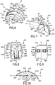
- said prosthesis 100 comprises a talar component 200, a preferred embodiment of which is illustrated in FIGS. Figures 6 to 10 and which is advantageously intended to be attached to the talus of a foot of the patient.
- the talar component 200 comprises an upper talar surface 201, which defines a first articular surface 202 of the prosthesis 100.
- said upper talar surface 201 extends between an anterior forewing edge 203 and a posterior posterior edge 204 according to a first mean direction AA 'mean and, preferably, between a talar side edge 205 and a medial talar edge 206 opposite a second mean direction BB', orthogonal to said first direction AA 'average.
- said first average direction AA ' may correspond to a first average anteroposterior direction in normal use of the prosthesis 100.
- Said second direction BB' mean may then advantageously correspond to a first median latero-medial direction.
- said talar lateral edge 205 and said medial talar edge 206 are rounded, chamfered.
- posterior anterior
- anterior anterior
- immediate anterior
- lateral lateral
- the talar component 200 also comprises a lower talar surface 207, opposite to said upper talar surface 201, and which is advantageously connected to the latter at said anterior forewing edge 203 and posterior posterior edge 204
- Said lower talar surface 207 is preferably intended to be positioned in contact in or on an area of the talus (or talus) of the patient specially prepared beforehand.
- the talar lower face 207 is defined by first and second substantially planar contiguous portions ( figure 7 ), which extend generally in respective secant planes, for example at an elevation angle of 30 ° of the first planar portion relative to the second planar portion.
- the first planar portion preferably forms an anterior portion of the lower talar face 207, while the second flat portion, which extends in a substantially horizontal plane in normal use of the prosthesis 100 according to the invention, advantageously forms a portion at the Once central and posterior talar underside 207.
- a leave may be provided at the junction of said first and second planar portions.
- the talar component 200 may also comprise a medial talar face 208 and an opposing talar lateral face 209, which respectively connect the medial talar edge 206 and the talar lateral edge 205 to said talar lower face 207.
- said talar medial face 208 and lateral talar surface 209 are generally convex towards the outside of the talar component 200, in order to better respect the natural anatomical conformation of the talus area at which the talar component 200 is intended to be put in place .
- the prosthesis 100 comprises a tibial component 300 ( Figures 11 to 15 ), intended to be attached to a lower end of the patient's tibia.
- Said tibial component 300 has a tibial upper face 301 and a tibial lower face 302 opposite.
- said tibial lower face 302 preferably extends, on the one hand, between an anterior tibial edge 303 and an opposite posterior tibial edge 304, preferably in a third mean direction CC 'and, on the other hand, between a tibial lateral edge 305 and an opposing tibial medial edge 306, preferably in a fourth mean direction DD 'orthogonal to said third mean direction CC'.
- said third average direction CC ' may correspond to a second average anteroposterior direction in normal use of the prosthesis 100.
- Said fourth direction DD' mean may then advantageously correspond to a second mean latero-medial direction.
- Said second mean antero-posterior direction and second medial latero-medial direction of the tibial component 300 are advantageously respectively parallel to said first mean anteroposterior direction and first medial lateromial direction of the talar component 200, in normal use of the prosthesis 100.
- the tibial upper face 301 and the tibial lower face 302 respectively extend in substantially parallel mean extension planes, said tibial component 300 being in the general form of a plate.
- Said upper tibial surface 301 is preferably intended to be positioned in contact in or on a zone of the tibia specially primed beforehand.
- the tibial component 300 can also comprise a tibial medial face 307 and an opposite tibial lateral face 308, which respectively connect the tibial medial edge 306 and the tibial lateral edge 305 to said tibial upper face 301.
- said tibial medial edge 306 is substantially rectilinear and said medial face tibial 307 is substantially flat ( Figures 11 to 14 ), so that the surgeon can accurately position said tibial component 300 in the patient's body, aligning said tibial medial face 307 along a rectilinear section made at the level of the medial malleolus.
- the tibial component 300 may comprise an anterior tibial surface 309 and an opposite posterior tibial surface 310, which in turn respectively connect the tibial anterior edge 303 and the posterior tibial edge 304 to said tibial upper face 301.
- said talar component 200 and / or said tibial component 300 respectively form a one-piece piece of a biocompatible and wear-resistant material.
- said talar component 200 and / or said tibial component 300 are made of a metallic material, for example chromium-cobalt CrCo alloy, stainless steel or titanium.
- said talar component 200 and said tibial component 300 are respectively a casting part.
- said talar component 200 and said tibial component 300 are respectively a machined part.
- suitable materials may be envisaged, such as for example a ceramic material, as well as other methods of manufacture (by injection, molding, sintering, etc.).
- the lower talar surface 207 of the talar component 200 and / or the upper tibial surface 301 of the tibial component 300 may be provided with a particular surface coating (for example porous titanium or hydroxyapatite), or have subject of a particular mechanical treatment (sandblasting, grooving, etc.), to promote bone attachment of talar component 200 to the talus and / or tibial component 300 to the corresponding tibia.
- a particular surface coating for example porous titanium or hydroxyapatite
- a particular mechanical treatment sandblasting, grooving, etc.
- the prosthesis 100 according to the invention also comprises an intermediate component 400 (or shoe, or insert) ( Figures 16 to 19 ), which is adapted to be interposed between said talar component 200 and said tibial component 300, as illustrated as an example to Figures 1 to 5 .
- Said intermediate component 400 comprises an intermediate upper face 401, preferably intended to come into contact with the tibial lower face 302 of the tibial component 300, and an opposite lower face 402 opposite, which is in turn preferably intended to come into contact with the face upper talar component 200 of the talar component 200.
- Said intermediate lower face 402 advantageously defines a second articular surface 403 of the prosthesis 100, designed to cooperate with said first articular surface 202 defined by the upper talar surface 201 of the talar component 200.
- said intermediate upper face 401 extends firstly between a first intermediate front edge 404 and a first intermediate rear edge 405 opposite (for example in a fifth direction EE 'mean) and, secondly, between a first intermediate lateral edge 406 and a first intermediate medial edge 407 opposite (for example in a sixth direction FF mean, orthogonal to said fifth direction EE 'mean).
- Said intermediate lower face 402 preferably extends, on the one hand, between a second intermediate front edge 408 and a second rear intermediate edge 409 opposite, in the said fifth direction EE 'mean and, on the other hand, between a second edge intermediate lateral 410 and a second intermediate medial edge 411 opposite, in said sixth direction FF 'mean.
- the intermediate component 400 may also comprise an intermediate medial face 412 and an intermediate lateral face 413 opposite, which respectively connect the first intermediate medial edge 407 and the first intermediate lateral edge 406 to said intermediate lower face 402.
- the intermediate medial face 412 is substantially flat, for reasons substantially identical to those described above in connection with the tibial medial face 307 of the tibial component 300, while the intermediate lateral face 413 may be generally curved, with a concavity oriented towards said intermediate medial face 412.
- the comp Intermediate element 400 may comprise an intermediate front face 414 and an opposite rear intermediate face 415, which in turn respectively connect the first front edge. intermediate 404 and the first intermediate posterior edge 405 to said intermediate lower face 402.
- the intermediate component 400 is capable of slidingly moving in contact with the talar component 200 in an average anteroposterior direction and, in particular, in a generally postero-anterior (i.e., posterior) stroke. forward) between the posterior posterior edge 204 (plantar flexion, figure 3 ) and the anterior forewing margin 203 (dorsal flexion, figure 5 ), via a so-called neutral interim position ( figure 4 ), according to the inclination affected by the foot of the patient relative to his tibia.
- a generally postero-anterior i.e., posterior
- said intermediate component 400 is a one-piece piece made of a material having a low coefficient of friction, for example a plastic material such as a high-density polyethylene (HDPE). It may be, for example, a machined or molded part.
- a plastic material such as a high-density polyethylene (HDPE).
- HDPE high-density polyethylene
- the prosthesis 100 could not comprise an intermediate component 400, the lower tibial surface 302 can then be designed to define by itself a second articular surface intended to cooperate directly with the first articular surface 202 defined by the upper talar surface 201 of the talar component 200.
- said first articular surface 202 is curved, convex, in said first direction AA 'means.
- the second articular surface 403 defined by the intermediate lower face 402 of the talar component 400 is preferably curved along said fifth direction EE 'mean.
- Said first articular surface 202 is preferably generally convex (that is to say with a concavity oriented towards the lower talar surface 207 of the talar component 200), while the second articular surface 403 is generally concave.
- an inverted configuration could be envisaged without departing from the scope of the invention, the first articular surface 202 being generally concave, while the second articular surface 403 is generally convex.
- said first articular surface 202 (and, preferably, said second articular surface 403) more specifically presents (each) the average general shape of a substantially frustoconical (fictitious) surface fraction derived from a fictitious cone which surface is preferably oriented so that its large base is oriented towards the external malleolus and that its small base is oriented towards the internal malleolus of the foot considered.
- the intermediate component 400 moves in frictional contact relative to the talar component 200, by cooperation of said first 202 and second 403 articular surfaces, the intermediate component 400 does not describe a strictly anteroposterior or postero-anterior trajectory, but at contrary a more or less curved trajectory.
- first 202 and second 403 articular surfaces could each have the average general shape of a cylindrical (fictional) surface fraction, so as to define an articular kinematic in which the intermediate component 400 moves in a substantially anterotic trajectory posterior or postero-anterior.
- said first articular surface 202 comprises at least two distinct curved surface portions, namely at least a first curved portion 202A and a second curved portion 202B, which each extend in said first direction AA 'mean, aligned with each other. one behind the other in said first mean direction AA ', said first curved portion 202A having a first curvature and said second curved portion 202B having a second curvature, in said first direction AA' mean.
- said first articular surface 202 is described by at least two distinct curvilinear portions (respectively designated on the figure 10 with the same references 202A and 202B as for the first and second corresponding curved portions), each preferably forming an arc whose concavity is preferably directed towards the lower talar face 207, said curvilinear portions having centers of curvature (possibly ) distinct from each other.
- said first 202A and second 202B curved portions of the first articular surface 202 are respectively broadly comparable to a first and a second fraction of (fictitious) substantially frustoconical surfaces, said first and second surface fractions being preferably respectively derived from a first and a second imaginary cones, virtual, respectively having a first and a second axis of rotation.
- the value of the half angle at the apex of each of said first and second fictitious cones is 8 °. The choice of this particular configuration helps to better reproduce the natural kinematics of the anatomical ankle.
- said first 202A and second 202B curved portions of the first articular surface 202 could be respectively broadly comparable to a first and a second fraction of substantially cylindrical surfaces, said first and second surface fractions being preferably respectively derived from a first and a second dummy cylinder, respectively having a first and a second axis of rotation.
- said first articular surface 202 has, as introduced above, the average general shape of a substantially frustoconical (fictitious) surface fraction resulting from a fictitious (or cylindrical) cone, this average general shape is more precisely defined, within the meaning of the invention, by the combination of at least a first and a second distinct fractions of substantially frustoconical (or cylindrical) surfaces.
- each of these substantially frustoconical surfaces is preferably oriented so that its large base is oriented towards the external malleolus and that its small base is oriented towards the internal malleolus of the foot considered.
- the first fraction of frustoconical surface corresponding to the first curved portion 202A has a radius of curvature which varies, in a latero-medial direction of said second direction BB 'mean, decreasingly between a large radius R 1 of curvature and a small radius r 1 of curvature.
- the second fraction of frustoconical surface corresponding to the second curved portion 202B, has a radius of curvature which varies, in a latero-medial direction, of said second direction BB 'mean, decreasingly between a large radius R 2 of curvature and a small radius r 2 of curvature.
- the latter may be respectively have a radius of curvature R ' 1 , R' 2 which is constant in said second mean direction BB 'mean.
- said first and second curvatures are different, so that one of said first 202A and second 202B curved portions is therefore more curved, ie more strongly curved, than the other.
- said first 202A and second 202B curved portions of the first articular surface 202 are respectively broadly comparable to a first and a second fraction of (frustoconical) substantially frustoconical surfaces
- such difference in curvature can result in the fact that the first fraction of frustoconical surface has a large radius R 1 of curvature and a small radius r 1 of curvature which are respectively different from the large radius R 2 of curvature and small radius r 2 of curvature respective portions of the second frustoconical surface fraction (R 1 ⁇ R 2 and r 1 ⁇ r 2 ).
- first 202A and second 202B curved parts are respectively broadly comparable to a first and a second fraction of substantially cylindrical surfaces
- a difference in curvature may result in the first cylindrical surface fraction having a radius R ' 1 of curvature different from the respective radius of curvature R' 2 of the second cylindrical surface fraction.
- the first articular surface 202 defined by the upper talar face 201 advantageously does not have the exact and perfect shape of a frustoconical (or cylindrical) surface portion, as envisaged above in alternative), but that it comprises on the contrary a particular localized variation in its average general curvature in said first direction AA 'average.
- the general kinematics of the prosthesis 100 is then not defined by a single rotation, but by at least two rotations with different radii, corresponding to at least two spatial configurations of the foot relative to the tibia. It is thus possible to generate a complex articular movement, with differentiated axes of rotation of the prosthetic joint between a plantar flexion position and a dorsal flexion position, and to approach even more faithfully the natural kinematic behavior of an anatomical ankle.
- said first curved portion 202A and said second curved portion 202B define (or contribute to defining at least in part) respectively an anterior portion and a posterior portion of said first articular surface 202.
- said first curved portion 202A preferably extends between the anterior talar edge 203 and the posterior talar edge 204 of the upper talar face 201 of the talar component 200, and preferably from said former talar edge 203 (or at least from the immediate vicinity of the latter) towards said posterior posterior edge 204.
- Said second curved portion 202B then extends respectively between said first curved portion 202A and said trailing posterior edge 204.
- said second curved portion 202B is contiguous with said first curved portion 202A and extends the latter to said posterior posterior edge 204 (or at least up to the immediate vicinity thereof) ).
- the first curved portion 202A and the second curved portion 202B are therefore aligned one behind the other in the first direction AA 'mean, the first curved portion 202A (anterior portion) being arranged in front of the second curved portion 202B (posterior portion) .
- said first articular surface 202 is described by at least two distinct and preferably abutting curvilinear portions, each preferably forming an arc, and preferably connecting the anterior forewing edge 203 to the posterior dorsal edge 204.
- Said first curved portion 202A then corresponds advantageously to a part of the first articular surface 202 with which the second articular surface 403 of the intermediate component 400 will cooperate, in a configuration of dorsal flexion of the patient's foot ( figure 5 ), while said second curved portion 202 corresponds to another part of the first articular surface 202 with which said second articulating surface 403 of the intermediate component 400 will cooperate, in plantar flexion configuration of the patient's foot ( figure 3 ).
- said first and second curvatures, as well as the relative positioning of said first and second axes of rotation, will be chosen so as to ensure a smooth and smooth transition between said first 202A and second 202B curved parts of the first articular surface 202.
- said first and second fractions of substantially frustoconical surfaces meet in a contact plane inclined at an angle of between 10 °. and 30 °, and preferably about 20 °, in the direction of said forward anterior edge 203 with respect to a vertical plane containing said second axis of rotation, said contact plane containing said first and second axes of rotation.
- said first curvature of the first curved portion 202A is greater than said second curvature of the second curved portion 202B, i.e. said first curved portion 202A of the first articular surface 202 affects, in the first direction AA 'mean, a curvature greater than that respective said second curved portion 202B of the first articular surface 202 (R 1 ⁇ R 2 and r 1 ⁇ r 2 , or R' 1 ⁇ R ' 2 ).
- said first articular surface 202 then advantageously has a more pronounced curvature in its portion. earlier than in its posterior portion.
- Such a configuration is particularly interesting, since it allows the patient to allow dorsal flexion with greater angular deflection, without the fact that the patient's talus is deported in an antero-posterior direction. that is to say towards the back. Equipped with the prosthesis 100 according to the invention, the patient can thus more easily bend his foot, for example during the phase of walking where the foot leaves the ground at the end of a step, or when he seeks to climb the steps of a staircase.
- said first curvature is constant or variable (in the first direction AA 'mean), while said second curvature is constant (in the first direction AA' mean).
- a first variable curvature may advantageously correspond to a particular embodiment in which the general shape of the first curved portion 202A is itself globally defined by the combination of a plurality n of distinct fractions of substantially frustoconical or cylindrical surfaces (and not by the only first fraction mentioned above), which fractions would have small r n and large R n rays (or radii R ' n ) of different curvature (and therefore nth different curvatures), advantageously decreasing in said first direction AA 'average.
- the implementation of such a first variable curvature advantageously allows d to further improve the amplitude of the angular deflection offered by the prosthesis 100 in dorsal flexion.
- said second curved portion 202B is preferably designed and sized so that it advantageously has an area greater than the respective area of said first curved portion 202A. This ensures better recovery of intra-articular efforts in plantar flexion, which improves both the stability and the life of the prosthesis 100.
- said talar lateral zone 210L and talar medial zone extend respectively from said talar anterior edge 203 (or at least from the immediate vicinity of the latter) to said posterior posterior edge 204 (or at least to the immediate vicinity of this last).
- Said lateral talar zone 210L then comprises a first lateral region 211L of said first curved portion 202A and a second lateral region 212L of said second curved portion 202B.
- Said medial talar area 210M comprises respectively a first medial region 211M of said first curved portion 202A and a second medial region 212M of said second curved portion 202B.
- the second lateral region 212L and second medial region 212M then preferably extend respectively said first lateral region 211L and first medial region 211L, in the first direction AA 'means.
- said talar lateral zone 210L and medial talar zone 210M thus form respectively continuous lateral and medial prosthetic condyle portions in the first direction AA 'mean.
- said first articular surface 202 also comprises a central talar zone 210C, which is interposed between said talar lateral zone 210L and said medial talar zone 210M.
- said central talar zone 210C extends, along said first direction AA 'average, from said anterior forewing edge 203 (or at least from the immediate vicinity of the latter) towards the posterior dorsal edge 204, and advantageously comprises a first central region 211C of said first curved portion 202A.
- said central talar zone 210C also comprises a second curved central region 213C which extends said first central region 211C towards the posterior posterior edge 204.
- said second central region 213C preferably does not constitute, as a that such, a central region of the second curve portion 202B.
- said second central region 213C advantageously has a third curvature, in the first direction AA 'mean, which is different from said second curvature of the second curved portion 202B.
- Said second curve portion 202B is then discontinuous in the second direction BB 'mean.
- said third curvature of the second central region 213C is advantageously greater than said second curvature.
- the second central region 213C is thus more strongly curved than the second lateral region 212L and second medial region 212M surrounding.
- said third curvature may be identical to said first curvature, the second central region 213C being in continuity with the first central region 211C.
- said second central region 213C then advantageously materializes a posterior central depression 214 in the middle envelope of said first articular surface 202.
- said central talar zone 210C of the first articular surface 202 may not extend to the edge posterior talar 204 of the upper talar surface 201.
- the space thus formed between said central talar zone 210C and said posterior posterior edge 204 may be left free or, on the contrary, preferably be filled by a complementary portion 215 upper face talar 201 full , and for example planar, so as to avoid the formation of an uncoated bone cutting zone.
- said intermediate lateral zone 416L and medial intermediate zone 416M advantageously have, in said fifth direction EE 'mean, curvatures respectively conjugated to the curvatures of said second lateral region 212L and second medial region 212M of the second curved portion 202B of said first articular surface 202.
- Said intermediate central zone 416C advantageously has, according to said fifth direction EE 'mean, a e curvature conjugate to the curvature of said first central region 211C of the first curved portion 202A of said first articular surface 202.
- said talar central zone 210C has a convex curvature along said second mean direction BB ', said talar lateral zone 210L and medial zone talar 210M respectively having a concave curvature in said second mean direction BB 'mean.
- the intermediate lateral zone 416L and the intermediate medial zone 416M are advantageously convex along said sixth mean direction FF ', whereas the intermediate central zone 416C is concave along the same direction FF' ( figure 17 ).
- said intermediate lateral zone 416L and intermediate medial zone 416M may advantageously be respectively in surface contact against said second lateral region 212L and second medial region 212M of the second curved portion 202B of the first articular surface 202.
- said intermediate central zone 416C may advantageously rest in surface contact with the first central region 211C of the first curved portion 202A of the first articular surface 202.
- said intermediate lateral zone 416L and intermediate medial zone 416M can not then, preferably, resting in surface contact against said first lateral region 211L and first medial region 211M of the first curved portion 202A of the first articular surface 202, due to their respective different curvatures.
- the cooperation of said first and second articular surfaces is advantageously not perfectly congruent.
- the intermediate component 400 advantageously remains free to slide and tilt slightly, laterally or medially, around an equilibrium position.
- the intermediate lateral zone 416L of the second articular surface 403 can advantageously come into linear contact with the first lateral region 211L of the first curved portion 202A of the first articular surface 202 defined by the upper talar face. 201 of the talar component 200.
- the intermediate medial zone 416M of said second articular surface 403 can advantageously come into linear contact with the first medial region 211M of the first curved portion 202A of the first surface.
- the intermediate component 400 advantageously has a certain limited latitude for rotation about a vertical axis.
- such a configuration advantageously makes it possible, to a certain extent, to compensate for a slight relative positioning defect of the talar 200 and tibial 300 components, which contributes to facilitating the placement of the prosthesis 100 by the surgeon in the patient's body. .
- the intermediate central zone 416C preferably has, in accordance with the foregoing, a curvature greater than that of the intermediate lateral zone 416L and intermediate medial zone 416M, it can then define, close to the second intermediate posterior edge 409, a protrusion 417 protruding from the surface of the intermediate lower face 402 ( figure 17 ).
- said posterior central depression 214 represented by the second central region 213C of the central talar zone 210C, as mentioned above
- said protrusion 417 can advantageously be erased in said posterior central depression 214.
- said tibial component 300 is designed to be movable relative to said intermediate component 400, said tibial 300 and intermediate 400 components then not being preferably mechanically interconnected.
- said tibial lower face 302 and said intermediate upper face 401 are preferably substantially planar and smooth, so that the tibial component 300 and the intermediate component 400 can come into planar surface contact against each other .
- the tibial component 300 and the intermediate component 400 are thus in contact with one another, and are movable relative to each other in three degrees of freedom, namely according to a mean antero-posterior directional translation, a mediolateral mean directional translation, and a rotation about an axis orthogonal to the contact plane of said tibial lower face 302 and intermediate upper face 401 therebetween.
- said tibial component 300 is designed to be fixed, that is to say secured, to said intermediate component 400, so as to advantageously suppress any degree of freedom between the tibial component 300 and the intermediate component 400.
- Such a fastening of the latter advantageously improves the stability of the prosthetic joint.
- said tibial component 300 and intermediate component 400 are adapted to be affixed to each other by means of first and second respective complementary securing elements, more preferably in a dovetail assembly.
- the tibial lower face 302 of the tibial component 300 is thus advantageously provided with a groove 311, for example of trapezoidal section, which advantageously forms said first securing element (or female member in the tail end). dove).
- the intermediate upper face 401 of the intermediate component 400 is reciprocally advantageously provided with a pin 418, which forms said second securing element (or male dovetail member).
- said post 418 projects from the surface of said intermediate upper face 401 and is of shape and dimensions complementary to that of said groove 311.
- said groove 311 extends longitudinally along said third middle direction CC 'from the face tibial component 309 of the tibial component 300, at which it opens out, towards the posterior tibial surface 310, and over at least half of the mean distance between said anterior tibial surface 309 and posterior tibial surface 310 ( Figures 12 and 14 ).
- said post 418 extends longitudinally along said fifth direction EE 'mean, from the intermediate front face 414 of the intermediate component 400, towards the intermediate rear face 415 thereof.
- the length of said stud 418 is smaller than the respective length of said groove 311 ( Figures 16 and 18 ).
- Said groove 311 is thus advantageously designed and configured to receive a narrow sliding said pin 418, said lower tibial face 302 and intermediate upper face 401 then being held pressed against each other.
- Such a relative dovetail assembly thus advantageously makes it possible to block at least any mediolateral translation and any rotation of the intermediate component 400 relative to the tibial component 300.
- said post 418 can be provided, at its posterior end of lateral slopes 419A, 419B (or chamfers) designed to facilitate, guide, the introduction of the pin 418 in the groove 311 during the relative assembly of the tibial component 300 and the intermediate component 400.
- said tibial component 300 and intermediate component 400 preferably furthermore comprise respectively complementary first and second abutment elements designed to limit or block the anteroposterior translation (c '). that is to say, from the front to the back) of the intermediate component 400 relative to the tibial component 300, said first and second stop elements being advantageously distinct from said first and second complementary securing elements.
- the limitation (and preferably the blocking) of the anteroposterior translation is advantageously not ensured (or, at least not exclusively) by the assembly of a tail. aronde itself, but by the cooperation of said first and second complementary abutment elements.
- said first and second abutment members respectively comprise a flange 312 positioned at least at level of the posterior tibial edge 304 of the tibial lower face 302 of the tibial component 300, and a clearance 420 formed at the intermediate upper face 401 of the intermediate component 400 (for example at the first intermediate posterior edge 405) and complementary profile to said flange 312.
- Said clearance 420 is thus designed and configured to receive said flange 312, said tibial lower face 302 and intermediate upper face 401 being advantageously in plane contact with one another.
- the cooperation of said flange 312 and clearance 420 thus limits, and preferably block, the anteroposterior stroke of the pin 418 in the groove 311. Obviously stop elements of different design could be implemented.
- said flange 312 is positioned at said posterior tibial edge 304, tibial lateral edge 305 and tibial medial edge 306 of the tibial lower face 302 of the tibial component 300, and advantageously extends substantially continuous along the edges 304, 305, 306 in question.
- Said flange 312 preferably has a rectangular section, constant or not.
- said clearance 420 is preferably arranged at the level of the first intermediate posterior edge 405, first intermediate lateral edge 406 and first intermediate medial edge 407 of the intermediate upper face 401 of said intermediate component 400, advantageously substantially continuously along the edges 405, 406, 407 in question.
- said tibial component 300 and intermediate component 400 are advantageously respectively provided with first 313A, 313B and second 421A, 421B complementary locking means.
- said first locking means 313A, 313B may, for example, take the form of notches 313A, 313B tooth saw provided in the rim 312 of the lower tibial face 302, for example symmetrically at the tibial lateral edge 305 and the tibial medial edge 306 of said tibial component 300.
- said second locking means 421A, 421B may to it, take the form, for example, pins 421A, 421B complementary shapes to said notches 313A, 313B sawtooth, arranged at the clearance 420 of the intermediate component 400 ( Figures 16 to 18 ).
- the tibial component 300 and the intermediate component 400 can thus be locked to one another by clipping, the local elastic deformation of the material forming the intermediate component 400 allowing the engagement of the lugs 421A, 421B of the latter in the notches 313A , 313B corresponding tibial component 300.
- first 313A, 313B and second 421A, 421B suitable complementary locking means may be considered in place of those just described.
- the tibial component 300 is designed to be fixed removably to the intermediate component 400, in particular to allow the replacement of the intermediate component 400 in case of degradation of the latter (wear, deformation, etc.).
- the first 313A, 313B and second 421A, 421B complementary locking means will be designed to allow reversible locking of the tibial component 300 and the intermediate component 400 therebetween.
- the intermediate component 400 may, for example, be provided with recesses 422A, 422B formed in the intermediate upper face 401 in the immediate vicinity of the lugs 421A, 421B forming said second locking means 421A, 421B, and designed to receive the end of an external instrument (not shown, for example a flat screwdriver).
- this external instrument advantageously allows local elastic deformation of the material forming the intermediate component 400 and a decoupling of the notches 313A, 313B and lugs 421A, 421B, thus allowing the uncoupling talar 300 and intermediate 400 components.
- the talar component 200 is provided at its lower talar surface 207 with at least one talar anchoring means 216A, designed to anchor the talar component 200 in the bone mass of the slope concerned.
- said talary anchoring means 216A is advantageously intended to be housed, during the establishment of the talar component 200 in the body of the patient, in a housing (or hole) corresponding previously practiced (or during the establishment of the talar component 200) by the surgeon in the bone mass of the talus.
- the talar component 200 is provided with two talar anchoring means 216A, 216B, formed by two talar pads 216A, 216B, for example cylindrical with a rounded head, which project from the lower talar surface 207 of the talar component 200.
- said talar pads 216A, 216B extend inclined towards the posterior dorsal edge 204.
- talar anchoring means 216 may be envisaged.
- each talar anchoring means 216A, 216B is thus advantageously connected to the lower talar face 207 by a respective talar leave 217A, 217B.
- Such a fillet 217A, 217B may be particularly unfavorable in the case, envisaged above, where the lower talar surface 207 is provided with a surface coating, since the presence of the latter tends, according to its thickness, to amplify the importance of said leave 217A, 217B, and thus to further impede the establishment of said talar component 200.
- said talar lower face 207 is advantageously provided with at least one talar bowl 218A, from the bottom of which said at least one talar anchoring means 216A projects from said lower talar surface 207.
- said lower talar face 207 is advantageously provided with a plurality of talar bowls 218A, 218B from respective bottom of which said tali blocks 216A, 216B protrude from said tibial upper face 301.
- said talar bowl 218A, 218B is advantageously dimensioned so that said fillet 217A, 217B is integrally contained in said talar bowl 218A 218B and therefore does not protrude from the surface of the lower talar surface 207.
- said talar component 200 can be placed in a relatively simple and precise way at the slope, the lower talar surface 207 being able to come into surface contact. perfect with the corresponding slope area, without the need for specific tools for drilling bone mass.
- the tibial component 300 is provided at its tibial upper face 301 with at least one tibial anchoring means 314A designed to anchor the tibial component 300 in the bone mass of the tibia concerned.
- said tibial anchoring means 314A is advantageously intended to be housed, during the introduction of the tibial component 300 into the body of the patient, into at least one housing (or hole) made beforehand (or during the introduction of the tibial component 300) by the surgeon in the bone mass of the tibia.
- the tibial component 300 is preferably provided with a plurality of tibial anchoring means 314A, 314B, 314C, 314D, for example formed of two tibial studs 314A, 314B with rounded head protruding from said upper tibial face 301 in the vicinity of the anterior tibial edge 303, and two tibial fins 314C, 314D, which project from said tibial upper face 301 in the vicinity of the posterior tibial edge 304.
- said tibial fins 314C, 314D have sharp or even sharp edges , to promote their penetration into the bone mass of the tibia.
- said tibial pads 314A, 314B and said tibial fins 314C, 314D extend inclined towards the posterior tibial edge 304.
- the angle of inclination of said tibial pads 314A, 314B and said tibial fins 314C, 314D will advantageously be chosen to facilitate the introduction of the tibial component 400 into the body of the patient, and its establishment in the tibia of the latter, limiting the necessary joint distraction.
- tibial anchor means (s) 314A, 314B, 314C, 314D may be contemplated.
- said at least one tibial anchoring means 314A is preferably connected to the upper face tibial 301, at its base, by a tibial leave 315A.
- Said upper tibial surface 301 is then advantageously provided with at least one tibial cup 316A, from the bottom of which said at least one tibial fixation means 314A projects from said tibial upper surface 301.
- each of the tibial pads 314A, 314B and each of the tibial fins 314C, 314D is thus advantageously connected to the tibial upper face 301 by a respective tibial leave 315A, 315B, 315A, 315B.
- Said upper tibial surface 301 is then advantageously provided with a plurality of tibial cups 316A, 316B, 316A, 316B from the respective bottom of which said tibial pads 314A, 314B and said tibial fins 314C, 314D project from said upper tibial surface 301 .
- the talar lateral edge 205 and the medial talar edge 206 of the talar component 200 are preferably respectively provided with a lateral talar notch 219L and a talar medial notch 219M, advantageously positioned symmetrically in the vicinity of the anterior forewing edge 203.
- Said lateral talar notch 219L and said talar medial notch 219M are advantageously designed to cooperate with an external instrument (not shown, for example a flat screwdriver), to allow ablation of the talar component 200, for example in case of unsatisfactory positioning or in the event of a medical complication justifying the removal of all or part of the prosthesis 100.
- the tibial lateral edge 305 and the tibial medial edge 306 of the tibial component 300 may advantageously be respectively provided with a tibial lateral notch 317L and a medial tibial notch 317M, advantageously positioned symmetrically to the neighborhood of the anterior tibial border 303 ( Figures 11, 12 and 14 ).
Landscapes
- Health & Medical Sciences (AREA)
- Orthopedic Medicine & Surgery (AREA)
- Cardiology (AREA)
- Oral & Maxillofacial Surgery (AREA)
- Transplantation (AREA)
- Engineering & Computer Science (AREA)
- Biomedical Technology (AREA)
- Heart & Thoracic Surgery (AREA)
- Vascular Medicine (AREA)
- Life Sciences & Earth Sciences (AREA)
- Animal Behavior & Ethology (AREA)
- General Health & Medical Sciences (AREA)
- Public Health (AREA)
- Veterinary Medicine (AREA)
- Prostheses (AREA)
Applications Claiming Priority (1)
| Application Number | Priority Date | Filing Date | Title |
|---|---|---|---|
| FR1758185A FR3070593A1 (fr) | 2017-09-05 | 2017-09-05 | Prothese de cheville amelioree |
Publications (2)
| Publication Number | Publication Date |
|---|---|
| EP3449876A1 true EP3449876A1 (de) | 2019-03-06 |
| EP3449876B1 EP3449876B1 (de) | 2020-04-15 |
Family
ID=60182749
Family Applications (1)
| Application Number | Title | Priority Date | Filing Date |
|---|---|---|---|
| EP18192345.9A Active EP3449876B1 (de) | 2017-09-05 | 2018-09-04 | Verbesserte knöchelprothese |
Country Status (5)
| Country | Link |
|---|---|
| US (1) | US10952865B2 (de) |
| EP (1) | EP3449876B1 (de) |
| CN (2) | CN109419574B (de) |
| ES (1) | ES2795350T3 (de) |
| FR (2) | FR3070593A1 (de) |
Cited By (1)
| Publication number | Priority date | Publication date | Assignee | Title |
|---|---|---|---|---|
| US11219530B2 (en) | 2018-04-24 | 2022-01-11 | Paragon 28, Inc. | Implants and methods of use and assembly |
Families Citing this family (14)
| Publication number | Priority date | Publication date | Assignee | Title |
|---|---|---|---|---|
| US10398562B2 (en) * | 2015-01-20 | 2019-09-03 | Exactech, Inc. | Talar implant for modifying joint kinematics |
| AU2016400080B2 (en) * | 2016-03-28 | 2019-10-17 | Wright Medical Technology, Inc. | Anterior resurfacing talar plate |
| KR102066837B1 (ko) * | 2017-08-29 | 2020-01-16 | 주식회사 코렌텍 | 인공발목관절 거골요소 |
| FR3070593A1 (fr) * | 2017-09-05 | 2019-03-08 | In2Bones | Prothese de cheville amelioree |
| FR3071400B1 (fr) * | 2017-09-28 | 2019-10-04 | Biotechni | Prothese de cheville comportant un implant talien, un implant tibial et un insert, kit incluant au moins une telle prothese, et guide de coupe pour la mise en place de l'implant tibial |
| TWI786139B (zh) * | 2018-06-22 | 2022-12-11 | 財團法人工業技術研究院 | 人工關節 |
| CN110013360A (zh) * | 2019-04-26 | 2019-07-16 | 中国人民解放军联勤保障部队第九二〇医院 | 一种高适形性胫骨-距骨间仿生配合关节 |
| CN110013364A (zh) * | 2019-04-26 | 2019-07-16 | 中国人民解放军联勤保障部队第九二〇医院 | 一种高适形性距骨上端仿生耐固接距骨替换件 |
| US11324601B2 (en) * | 2019-09-30 | 2022-05-10 | Paragon Advanced Technologies, Inc. | Talus implant |
| AU2021289599A1 (en) * | 2020-06-10 | 2023-02-09 | Paragon 28, Inc. | Implants and methods of use, assembly and fabrication |
| US20240024120A1 (en) * | 2021-02-24 | 2024-01-25 | Wright Medical Technology, Inc. | Implant peg with multiple components |
| US20220313446A1 (en) * | 2021-04-01 | 2022-10-06 | Wright Medical Technology, Inc. | Low-profile prostheses, systems, and methods |
| CN113827378B (zh) * | 2021-11-24 | 2022-05-03 | 北京爱康宜诚医疗器材有限公司 | 踝关节胫骨侧假体 |
| WO2023250428A2 (en) * | 2022-06-22 | 2023-12-28 | Paragon 28, Inc. | Orthopedic implants and instruments |
Citations (3)
| Publication number | Priority date | Publication date | Assignee | Title |
|---|---|---|---|---|
| FR2905259A1 (fr) * | 2006-09-05 | 2008-03-07 | Ceram Sarl I | Prothese de cheville |
| US20140180427A1 (en) * | 2012-09-20 | 2014-06-26 | Michael G. Harding, Jr. | Ankle Replacement Devices and Methods of Making and Using the Same |
| WO2014149952A1 (en) * | 2013-03-15 | 2014-09-25 | Drexel University | Prosthetic ankle with conic saddle shaped joint |
Family Cites Families (24)
| Publication number | Priority date | Publication date | Assignee | Title |
|---|---|---|---|---|
| US4069518A (en) * | 1976-08-31 | 1978-01-24 | Groth Jr Harry E | Total ankle prosthesis |
| US4470158A (en) * | 1978-03-10 | 1984-09-11 | Biomedical Engineering Corp. | Joint endoprosthesis |
| US4309778A (en) * | 1979-07-02 | 1982-01-12 | Biomedical Engineering Corp. | New Jersey meniscal bearing knee replacement |
| FR2760353B1 (fr) * | 1997-03-10 | 1999-07-02 | Tornier Sa | Prothese de cheville |
| US6039763A (en) * | 1998-10-27 | 2000-03-21 | Disc Replacement Technologies, Inc. | Articulating spinal disc prosthesis |
| IT1310371B1 (it) * | 1999-05-13 | 2002-02-13 | Ist Ortopedici Rizzoli | Dispositivo di protesi per articolazione umana, in particolare perarticolazione della tibotarsica e relativo metodo di impianto. |
| US7615082B2 (en) * | 2002-03-22 | 2009-11-10 | Hjs Gelenk System Gmbh | Artificial joint |
| US6863691B2 (en) * | 2002-04-29 | 2005-03-08 | Timothy J. Short | Ankle implant |
| US7025790B2 (en) * | 2002-06-27 | 2006-04-11 | Concepts In Medicine Iii, L.L.C. | Ankle joint prosthesis and its method of implantation |
| ATE543464T1 (de) * | 2003-10-14 | 2012-02-15 | Univ Iowa Res Found | Fussgelenkprotehse |
| WO2006023824A2 (en) * | 2004-08-19 | 2006-03-02 | Kinetikos Medical Incorporated | Ankle prosthesis and method of curved resection |
| US8012217B2 (en) * | 2008-07-03 | 2011-09-06 | Fellowship of Orthopaedic Researchers, LLC | Talar implants and methods of use |
| US8690956B2 (en) * | 2010-08-23 | 2014-04-08 | Fellowship Of Orthopaedic Researchers, Inc. | Talar implants and methods of use |
| US9468532B2 (en) * | 2011-11-01 | 2016-10-18 | Adam D. Perler | Semi constrained polyaxial endoprosthetic ankle joint replacement implant |
| US8668743B2 (en) * | 2010-11-02 | 2014-03-11 | Adam D. Perler | Prosthetic device with multi-axis dual bearing assembly and methods for resection |
| US8597361B2 (en) * | 2010-11-11 | 2013-12-03 | Bioshift, Llc | Joint implant fixation system |
| GB2500918A (en) * | 2012-04-05 | 2013-10-09 | Biomet Uk Healthcare Ltd | A prosthetic ankle with sliding engaging components |
| GB201218081D0 (en) * | 2012-10-09 | 2012-11-21 | Matortho Ltd | Prosthesis |
| US9750613B2 (en) * | 2012-11-12 | 2017-09-05 | Wright Medical Technology, Inc. | Stabilized total ankle prosthesis |
| JP6573908B2 (ja) * | 2014-05-12 | 2019-09-11 | インテグラ・ライフサイエンシーズ・コーポレイションIntegra LifeSciences Corporation | 人工関節全置換術人工装具 |
| US10398562B2 (en) * | 2015-01-20 | 2019-09-03 | Exactech, Inc. | Talar implant for modifying joint kinematics |
| US9877839B2 (en) * | 2015-08-25 | 2018-01-30 | Wright Medical Technology, Inc. | Modular talar fixation method and system |
| WO2018053439A1 (en) * | 2016-09-16 | 2018-03-22 | Dt Medtech, Llc | Ankle prosthesis and methods of using the same |
| FR3070593A1 (fr) * | 2017-09-05 | 2019-03-08 | In2Bones | Prothese de cheville amelioree |
-
2017
- 2017-09-05 FR FR1758185A patent/FR3070593A1/fr active Pending
-
2018
- 2018-09-04 ES ES18192345T patent/ES2795350T3/es active Active
- 2018-09-04 EP EP18192345.9A patent/EP3449876B1/de active Active
- 2018-09-04 US US16/120,942 patent/US10952865B2/en active Active
- 2018-09-05 CN CN201811030372.3A patent/CN109419574B/zh active Active
- 2018-09-05 CN CN202310775211.1A patent/CN116999219A/zh active Pending
-
2023
- 2023-01-27 FR FR2300764A patent/FR3132204A1/fr active Pending
Patent Citations (3)
| Publication number | Priority date | Publication date | Assignee | Title |
|---|---|---|---|---|
| FR2905259A1 (fr) * | 2006-09-05 | 2008-03-07 | Ceram Sarl I | Prothese de cheville |
| US20140180427A1 (en) * | 2012-09-20 | 2014-06-26 | Michael G. Harding, Jr. | Ankle Replacement Devices and Methods of Making and Using the Same |
| WO2014149952A1 (en) * | 2013-03-15 | 2014-09-25 | Drexel University | Prosthetic ankle with conic saddle shaped joint |
Cited By (1)
| Publication number | Priority date | Publication date | Assignee | Title |
|---|---|---|---|---|
| US11219530B2 (en) | 2018-04-24 | 2022-01-11 | Paragon 28, Inc. | Implants and methods of use and assembly |
Also Published As
| Publication number | Publication date |
|---|---|
| ES2795350T3 (es) | 2020-11-23 |
| CN109419574B (zh) | 2023-07-14 |
| FR3132204A1 (fr) | 2023-08-04 |
| US20190070012A1 (en) | 2019-03-07 |
| FR3070593A1 (fr) | 2019-03-08 |
| US10952865B2 (en) | 2021-03-23 |
| CN116999219A (zh) | 2023-11-07 |
| EP3449876B1 (de) | 2020-04-15 |
| CN109419574A (zh) | 2019-03-05 |
Similar Documents
| Publication | Publication Date | Title |
|---|---|---|
| EP3449876B1 (de) | Verbesserte knöchelprothese | |
| CA2726034C (fr) | Prothese totale de genou | |
| EP1025819B1 (de) | Knieprothese mit relativ zu einem Zapfen bewegbarem Einsatz | |
| EP1354571B1 (de) | Ganzknieprothese | |
| EP1196118B1 (de) | Neuartige knieprothese | |
| EP2547291B1 (de) | Knieprothese mit gemischter meniskusscheibe | |
| EP3687455B1 (de) | Knöchelprothese mit einem talusimplantat, einem tibiaimplantat und einem einsatz sowie kit mit mindestens einer solchen prothese | |
| FR2940760A1 (fr) | Implant orthopedique pour arthroplastie digitale | |
| EP1040796A1 (de) | In der anteroposterioren Richtung stabilisierte Knieprothese | |
| EP1611872A1 (de) | Schulter- oder Hüftprothese | |
| EP0758218A1 (de) | Knieprothese mit beweglichem meniskus | |
| CH630520A5 (fr) | Prothese d'articulation du genou. | |
| FR2682287A1 (fr) | Prothese de genou. | |
| FR2778332A1 (fr) | Prothese de genou, unicompartimentale et a patin adaptable | |
| FR2637494A1 (fr) | Element femoral d'une endoprothese de hanche | |
| EP3395272A1 (de) | Arthrodese-implantat und chirurgisches set, das ein solches implantat umfasst | |
| EP3854355B1 (de) | Implantierbare komponente mit verbesserter verankerung für knöchelprothese und eine solche komponente umfassende knöchelprothese | |
| WO2016124731A1 (fr) | Prothese totale de genou avec couple de frottement ceramique sur ceramique et plateau mobile en ceramique | |
| FR2913591A1 (fr) | Prothese totale du genou, du type dit "postero-stabilisee" | |
| FR2976176A1 (fr) | Prothese totale du genou, et gamme d'elements modulaires permettant l'obtention de cette prothese | |
| FR2684291A1 (fr) | Prothese de cheville. | |
| FR3008606A1 (fr) | Prothese totale de genou | |
| EP0707839A1 (de) | Oberschenkelgelenkprothese des Knies | |
| FR2901690A1 (fr) | Prothese totale du genou a glissement | |
| EP1543802A2 (de) | Stabilisierte Knieprothese mit drehbarem Tibialager |
Legal Events
| Date | Code | Title | Description |
|---|---|---|---|
| PUAI | Public reference made under article 153(3) epc to a published international application that has entered the european phase |
Free format text: ORIGINAL CODE: 0009012 |
|
| STAA | Information on the status of an ep patent application or granted ep patent |
Free format text: STATUS: THE APPLICATION HAS BEEN PUBLISHED |
|
| AK | Designated contracting states |
Kind code of ref document: A1 Designated state(s): AL AT BE BG CH CY CZ DE DK EE ES FI FR GB GR HR HU IE IS IT LI LT LU LV MC MK MT NL NO PL PT RO RS SE SI SK SM TR |
|
| AX | Request for extension of the european patent |
Extension state: BA ME |
|
| STAA | Information on the status of an ep patent application or granted ep patent |
Free format text: STATUS: REQUEST FOR EXAMINATION WAS MADE |
|
| 17P | Request for examination filed |
Effective date: 20190731 |
|
| RBV | Designated contracting states (corrected) |
Designated state(s): AL AT BE BG CH CY CZ DE DK EE ES FI FR GB GR HR HU IE IS IT LI LT LU LV MC MK MT NL NO PL PT RO RS SE SI SK SM TR |
|
| GRAP | Despatch of communication of intention to grant a patent |
Free format text: ORIGINAL CODE: EPIDOSNIGR1 |
|
| STAA | Information on the status of an ep patent application or granted ep patent |
Free format text: STATUS: GRANT OF PATENT IS INTENDED |
|
| INTG | Intention to grant announced |
Effective date: 20191129 |
|
| RIN1 | Information on inventor provided before grant (corrected) |
Inventor name: LEEMRIJSE, THIBAUT, JEAN, PIERRE, HENRY Inventor name: BESSE, JEAN-LUC, PIERRE, MARIE Inventor name: AGREN, PER-HENRIK Inventor name: PUTZEYS, PIT Inventor name: PAUL, LAURENT, FRANCOIS, RENE |
|
| GRAS | Grant fee paid |
Free format text: ORIGINAL CODE: EPIDOSNIGR3 |
|
| GRAA | (expected) grant |
Free format text: ORIGINAL CODE: 0009210 |
|
| STAA | Information on the status of an ep patent application or granted ep patent |
Free format text: STATUS: THE PATENT HAS BEEN GRANTED |
|
| AK | Designated contracting states |
Kind code of ref document: B1 Designated state(s): AL AT BE BG CH CY CZ DE DK EE ES FI FR GB GR HR HU IE IS IT LI LT LU LV MC MK MT NL NO PL PT RO RS SE SI SK SM TR |
|
| REG | Reference to a national code |
Ref country code: CH Ref legal event code: EP |
|
| REG | Reference to a national code |
Ref country code: DE Ref legal event code: R096 Ref document number: 602018003779 Country of ref document: DE |
|
| REG | Reference to a national code |
Ref country code: IE Ref legal event code: FG4D Free format text: LANGUAGE OF EP DOCUMENT: FRENCH |
|
| REG | Reference to a national code |
Ref country code: CH Ref legal event code: NV Representative=s name: CABINET GERMAIN AND MAUREAU, CH Ref country code: AT Ref legal event code: REF Ref document number: 1256418 Country of ref document: AT Kind code of ref document: T Effective date: 20200515 |
|
| REG | Reference to a national code |
Ref country code: NL Ref legal event code: FP |
|
| REG | Reference to a national code |
Ref country code: LT Ref legal event code: MG4D |
|
| PG25 | Lapsed in a contracting state [announced via postgrant information from national office to epo] |
Ref country code: IS Free format text: LAPSE BECAUSE OF FAILURE TO SUBMIT A TRANSLATION OF THE DESCRIPTION OR TO PAY THE FEE WITHIN THE PRESCRIBED TIME-LIMIT Effective date: 20200815 Ref country code: SE Free format text: LAPSE BECAUSE OF FAILURE TO SUBMIT A TRANSLATION OF THE DESCRIPTION OR TO PAY THE FEE WITHIN THE PRESCRIBED TIME-LIMIT Effective date: 20200415 Ref country code: PT Free format text: LAPSE BECAUSE OF FAILURE TO SUBMIT A TRANSLATION OF THE DESCRIPTION OR TO PAY THE FEE WITHIN THE PRESCRIBED TIME-LIMIT Effective date: 20200817 Ref country code: GR Free format text: LAPSE BECAUSE OF FAILURE TO SUBMIT A TRANSLATION OF THE DESCRIPTION OR TO PAY THE FEE WITHIN THE PRESCRIBED TIME-LIMIT Effective date: 20200716 Ref country code: NO Free format text: LAPSE BECAUSE OF FAILURE TO SUBMIT A TRANSLATION OF THE DESCRIPTION OR TO PAY THE FEE WITHIN THE PRESCRIBED TIME-LIMIT Effective date: 20200715 Ref country code: LT Free format text: LAPSE BECAUSE OF FAILURE TO SUBMIT A TRANSLATION OF THE DESCRIPTION OR TO PAY THE FEE WITHIN THE PRESCRIBED TIME-LIMIT Effective date: 20200415 Ref country code: FI Free format text: LAPSE BECAUSE OF FAILURE TO SUBMIT A TRANSLATION OF THE DESCRIPTION OR TO PAY THE FEE WITHIN THE PRESCRIBED TIME-LIMIT Effective date: 20200415 |
|
| REG | Reference to a national code |
Ref country code: AT Ref legal event code: MK05 Ref document number: 1256418 Country of ref document: AT Kind code of ref document: T Effective date: 20200415 |
|
| REG | Reference to a national code |
Ref country code: ES Ref legal event code: FG2A Ref document number: 2795350 Country of ref document: ES Kind code of ref document: T3 Effective date: 20201123 |
|
| PG25 | Lapsed in a contracting state [announced via postgrant information from national office to epo] |
Ref country code: LV Free format text: LAPSE BECAUSE OF FAILURE TO SUBMIT A TRANSLATION OF THE DESCRIPTION OR TO PAY THE FEE WITHIN THE PRESCRIBED TIME-LIMIT Effective date: 20200415 Ref country code: HR Free format text: LAPSE BECAUSE OF FAILURE TO SUBMIT A TRANSLATION OF THE DESCRIPTION OR TO PAY THE FEE WITHIN THE PRESCRIBED TIME-LIMIT Effective date: 20200415 Ref country code: RS Free format text: LAPSE BECAUSE OF FAILURE TO SUBMIT A TRANSLATION OF THE DESCRIPTION OR TO PAY THE FEE WITHIN THE PRESCRIBED TIME-LIMIT Effective date: 20200415 Ref country code: BG Free format text: LAPSE BECAUSE OF FAILURE TO SUBMIT A TRANSLATION OF THE DESCRIPTION OR TO PAY THE FEE WITHIN THE PRESCRIBED TIME-LIMIT Effective date: 20200715 |
|
| PG25 | Lapsed in a contracting state [announced via postgrant information from national office to epo] |
Ref country code: AL Free format text: LAPSE BECAUSE OF FAILURE TO SUBMIT A TRANSLATION OF THE DESCRIPTION OR TO PAY THE FEE WITHIN THE PRESCRIBED TIME-LIMIT Effective date: 20200415 |
|
| REG | Reference to a national code |
Ref country code: DE Ref legal event code: R097 Ref document number: 602018003779 Country of ref document: DE |
|
| PG25 | Lapsed in a contracting state [announced via postgrant information from national office to epo] |
Ref country code: SM Free format text: LAPSE BECAUSE OF FAILURE TO SUBMIT A TRANSLATION OF THE DESCRIPTION OR TO PAY THE FEE WITHIN THE PRESCRIBED TIME-LIMIT Effective date: 20200415 Ref country code: CZ Free format text: LAPSE BECAUSE OF FAILURE TO SUBMIT A TRANSLATION OF THE DESCRIPTION OR TO PAY THE FEE WITHIN THE PRESCRIBED TIME-LIMIT Effective date: 20200415 Ref country code: AT Free format text: LAPSE BECAUSE OF FAILURE TO SUBMIT A TRANSLATION OF THE DESCRIPTION OR TO PAY THE FEE WITHIN THE PRESCRIBED TIME-LIMIT Effective date: 20200415 Ref country code: DK Free format text: LAPSE BECAUSE OF FAILURE TO SUBMIT A TRANSLATION OF THE DESCRIPTION OR TO PAY THE FEE WITHIN THE PRESCRIBED TIME-LIMIT Effective date: 20200415 Ref country code: RO Free format text: LAPSE BECAUSE OF FAILURE TO SUBMIT A TRANSLATION OF THE DESCRIPTION OR TO PAY THE FEE WITHIN THE PRESCRIBED TIME-LIMIT Effective date: 20200415 Ref country code: EE Free format text: LAPSE BECAUSE OF FAILURE TO SUBMIT A TRANSLATION OF THE DESCRIPTION OR TO PAY THE FEE WITHIN THE PRESCRIBED TIME-LIMIT Effective date: 20200415 |
|
| PLBE | No opposition filed within time limit |
Free format text: ORIGINAL CODE: 0009261 |
|
| STAA | Information on the status of an ep patent application or granted ep patent |
Free format text: STATUS: NO OPPOSITION FILED WITHIN TIME LIMIT |
|
| PG25 | Lapsed in a contracting state [announced via postgrant information from national office to epo] |
Ref country code: PL Free format text: LAPSE BECAUSE OF FAILURE TO SUBMIT A TRANSLATION OF THE DESCRIPTION OR TO PAY THE FEE WITHIN THE PRESCRIBED TIME-LIMIT Effective date: 20200415 Ref country code: SK Free format text: LAPSE BECAUSE OF FAILURE TO SUBMIT A TRANSLATION OF THE DESCRIPTION OR TO PAY THE FEE WITHIN THE PRESCRIBED TIME-LIMIT Effective date: 20200415 |
|
| 26N | No opposition filed |
Effective date: 20210118 |
|
| PG25 | Lapsed in a contracting state [announced via postgrant information from national office to epo] |
Ref country code: SI Free format text: LAPSE BECAUSE OF FAILURE TO SUBMIT A TRANSLATION OF THE DESCRIPTION OR TO PAY THE FEE WITHIN THE PRESCRIBED TIME-LIMIT Effective date: 20200415 |
|
| REG | Reference to a national code |
Ref country code: BE Ref legal event code: MM Effective date: 20200930 |
|
| PG25 | Lapsed in a contracting state [announced via postgrant information from national office to epo] |
Ref country code: LU Free format text: LAPSE BECAUSE OF NON-PAYMENT OF DUE FEES Effective date: 20200904 |
|
| PG25 | Lapsed in a contracting state [announced via postgrant information from national office to epo] |
Ref country code: BE Free format text: LAPSE BECAUSE OF NON-PAYMENT OF DUE FEES Effective date: 20200930 |
|
| PG25 | Lapsed in a contracting state [announced via postgrant information from national office to epo] |
Ref country code: TR Free format text: LAPSE BECAUSE OF FAILURE TO SUBMIT A TRANSLATION OF THE DESCRIPTION OR TO PAY THE FEE WITHIN THE PRESCRIBED TIME-LIMIT Effective date: 20200415 Ref country code: MT Free format text: LAPSE BECAUSE OF FAILURE TO SUBMIT A TRANSLATION OF THE DESCRIPTION OR TO PAY THE FEE WITHIN THE PRESCRIBED TIME-LIMIT Effective date: 20200415 Ref country code: CY Free format text: LAPSE BECAUSE OF FAILURE TO SUBMIT A TRANSLATION OF THE DESCRIPTION OR TO PAY THE FEE WITHIN THE PRESCRIBED TIME-LIMIT Effective date: 20200415 |
|
| PG25 | Lapsed in a contracting state [announced via postgrant information from national office to epo] |
Ref country code: MK Free format text: LAPSE BECAUSE OF FAILURE TO SUBMIT A TRANSLATION OF THE DESCRIPTION OR TO PAY THE FEE WITHIN THE PRESCRIBED TIME-LIMIT Effective date: 20200415 Ref country code: MC Free format text: LAPSE BECAUSE OF FAILURE TO SUBMIT A TRANSLATION OF THE DESCRIPTION OR TO PAY THE FEE WITHIN THE PRESCRIBED TIME-LIMIT Effective date: 20200415 |
|
| PGFP | Annual fee paid to national office [announced via postgrant information from national office to epo] |
Ref country code: DE Payment date: 20221012 Year of fee payment: 5 |
|
| PGFP | Annual fee paid to national office [announced via postgrant information from national office to epo] |
Ref country code: NL Payment date: 20230926 Year of fee payment: 6 Ref country code: IT Payment date: 20230921 Year of fee payment: 6 Ref country code: IE Payment date: 20230927 Year of fee payment: 6 Ref country code: GB Payment date: 20230927 Year of fee payment: 6 |
|
| PGFP | Annual fee paid to national office [announced via postgrant information from national office to epo] |
Ref country code: FR Payment date: 20230925 Year of fee payment: 6 |
|
| PGFP | Annual fee paid to national office [announced via postgrant information from national office to epo] |
Ref country code: ES Payment date: 20231002 Year of fee payment: 6 |
|
| REG | Reference to a national code |
Ref country code: DE Ref legal event code: R119 Ref document number: 602018003779 Country of ref document: DE |
|
| PGFP | Annual fee paid to national office [announced via postgrant information from national office to epo] |
Ref country code: CH Payment date: 20240307 Year of fee payment: 6 |