EP3448787B1 - Förder-/ziehrollsystem mit abnehmbaren elastomeren zuführabdeckungen und verfahren zum ersetzen der abdeckungen - Google Patents
Förder-/ziehrollsystem mit abnehmbaren elastomeren zuführabdeckungen und verfahren zum ersetzen der abdeckungen Download PDFInfo
- Publication number
- EP3448787B1 EP3448787B1 EP17790352.3A EP17790352A EP3448787B1 EP 3448787 B1 EP3448787 B1 EP 3448787B1 EP 17790352 A EP17790352 A EP 17790352A EP 3448787 B1 EP3448787 B1 EP 3448787B1
- Authority
- EP
- European Patent Office
- Prior art keywords
- feed
- roll
- feed cover
- replaceable flexible
- elastomer
- Prior art date
- Legal status (The legal status is an assumption and is not a legal conclusion. Google has not performed a legal analysis and makes no representation as to the accuracy of the status listed.)
- Active
Links
Images





Classifications
-
- B—PERFORMING OPERATIONS; TRANSPORTING
- B65—CONVEYING; PACKING; STORING; HANDLING THIN OR FILAMENTARY MATERIAL
- B65G—TRANSPORT OR STORAGE DEVICES, e.g. CONVEYORS FOR LOADING OR TIPPING, SHOP CONVEYOR SYSTEMS OR PNEUMATIC TUBE CONVEYORS
- B65G47/00—Article or material-handling devices associated with conveyors; Methods employing such devices
-
- B—PERFORMING OPERATIONS; TRANSPORTING
- B65—CONVEYING; PACKING; STORING; HANDLING THIN OR FILAMENTARY MATERIAL
- B65H—HANDLING THIN OR FILAMENTARY MATERIAL, e.g. SHEETS, WEBS, CABLES
- B65H3/00—Separating articles from piles
- B65H3/02—Separating articles from piles using friction forces between articles and separator
- B65H3/06—Rollers or like rotary separators
- B65H3/0638—Construction of the rollers or like rotary separators
-
- B—PERFORMING OPERATIONS; TRANSPORTING
- B65—CONVEYING; PACKING; STORING; HANDLING THIN OR FILAMENTARY MATERIAL
- B65H—HANDLING THIN OR FILAMENTARY MATERIAL, e.g. SHEETS, WEBS, CABLES
- B65H5/00—Feeding articles separated from piles; Feeding articles to machines
- B65H5/06—Feeding articles separated from piles; Feeding articles to machines by rollers or balls, e.g. between rollers
-
- B—PERFORMING OPERATIONS; TRANSPORTING
- B65—CONVEYING; PACKING; STORING; HANDLING THIN OR FILAMENTARY MATERIAL
- B65H—HANDLING THIN OR FILAMENTARY MATERIAL, e.g. SHEETS, WEBS, CABLES
- B65H2402/00—Constructional details of the handling apparatus
- B65H2402/50—Machine elements
- B65H2402/51—Joints, e.g. riveted or magnetic joints
-
- B—PERFORMING OPERATIONS; TRANSPORTING
- B65—CONVEYING; PACKING; STORING; HANDLING THIN OR FILAMENTARY MATERIAL
- B65H—HANDLING THIN OR FILAMENTARY MATERIAL, e.g. SHEETS, WEBS, CABLES
- B65H2404/00—Parts for transporting or guiding the handled material
- B65H2404/10—Rollers
- B65H2404/11—Details of cross-section or profile
- B65H2404/114—Built-up elements
-
- B—PERFORMING OPERATIONS; TRANSPORTING
- B65—CONVEYING; PACKING; STORING; HANDLING THIN OR FILAMENTARY MATERIAL
- B65H—HANDLING THIN OR FILAMENTARY MATERIAL, e.g. SHEETS, WEBS, CABLES
- B65H2404/00—Parts for transporting or guiding the handled material
- B65H2404/10—Rollers
- B65H2404/18—Rollers composed of several layers
- B65H2404/181—Rollers composed of several layers with cavities or projections at least at one layer
-
- B—PERFORMING OPERATIONS; TRANSPORTING
- B65—CONVEYING; PACKING; STORING; HANDLING THIN OR FILAMENTARY MATERIAL
- B65H—HANDLING THIN OR FILAMENTARY MATERIAL, e.g. SHEETS, WEBS, CABLES
- B65H2404/00—Parts for transporting or guiding the handled material
- B65H2404/10—Rollers
- B65H2404/18—Rollers composed of several layers
- B65H2404/185—Rollers composed of several layers easy deformable
-
- B—PERFORMING OPERATIONS; TRANSPORTING
- B65—CONVEYING; PACKING; STORING; HANDLING THIN OR FILAMENTARY MATERIAL
- B65H—HANDLING THIN OR FILAMENTARY MATERIAL, e.g. SHEETS, WEBS, CABLES
- B65H2404/00—Parts for transporting or guiding the handled material
- B65H2404/50—Surface of the elements in contact with the forwarded or guided material
- B65H2404/55—Built-up surface, e.g. arrangement for attaching the surface to the forwarding or guiding element
- B65H2404/551—Non permanent attachment, i.e. allowing interchange ability of the surface
- B65H2404/5511—Non permanent attachment, i.e. allowing interchange ability
-
- B—PERFORMING OPERATIONS; TRANSPORTING
- B65—CONVEYING; PACKING; STORING; HANDLING THIN OR FILAMENTARY MATERIAL
- B65H—HANDLING THIN OR FILAMENTARY MATERIAL, e.g. SHEETS, WEBS, CABLES
- B65H2601/00—Problem to be solved or advantage achieved
- B65H2601/30—Facilitating or easing
- B65H2601/32—Facilitating or easing entities relating to handling machine
- B65H2601/324—Removability or inter-changeability of machine parts, e.g. for maintenance
-
- B—PERFORMING OPERATIONS; TRANSPORTING
- B65—CONVEYING; PACKING; STORING; HANDLING THIN OR FILAMENTARY MATERIAL
- B65H—HANDLING THIN OR FILAMENTARY MATERIAL, e.g. SHEETS, WEBS, CABLES
- B65H2701/00—Handled material; Storage means
- B65H2701/10—Handled articles or webs
- B65H2701/17—Nature of material
- B65H2701/176—Cardboard
- B65H2701/1764—Cut-out, single-layer, e.g. flat blanks for boxes
Definitions
- the present invention relates to feeder machines for corrugated sheets, and to pull roll systems having elastomeric feed covers for such machines. More particularly, the invention relates to a feeder machine system having replaceable feed covers and to a method for changing or renewing feeder machine feed covers.
- a known process for converting corrugated sheets from a blank sheet into a useable form starts with a feed end section of a converting or finishing machine where blank sheets are fed from a hopper through the feed end section into following machine sections.
- the feeding process typically uses a lead edge feeder and a set of rollers forming a nip that receives the sheets, pulls them into the machine and feeds them to the next stage of the machine.
- the surface of one of the rolls of the set may be covered with an elastomeric layer, while the other roll has a knurled surface.
- This set of rollers may be referred to herein as "feed/pull rolls" for convenience.
- the feed/pull rolls, and in particular the elastomeric (e.g., nitrile rubber or urethane) covers for such rolls wear with use and feeding performance suffers.
- elastomer cover wear becomes excessive, there is insufficient grip to reliably pull a sheet from beneath a stack of sheets in a hopper.
- the function of a feed/pull roll set in a finishing machine is to grip a corrugated sheet sufficiently to pull it out from the bottom of a stack of sheets in a supply hopper after a lead edge feeder initiates the feed.
- the feed/pull set accepts the sheet that has been accelerated to machine speed by the lead edge feed system.
- the lead edge feed system transfers the sheet a distance beyond the feed/pull roll nip so that the lead edge feed system and the feed/pull roll nip work in concert to transfer the sheet to the next stage of the finishing machine. That is, the feed/pull roll set transfers the sheet at machine speed to the next hand-off point, which typically may be a vacuum transfer unit, print / impression nip, or a pull roll set nip.
- the feed/pull roll set includes upper and lower rolls which are adjustably spaced apart to set up an opening or inter-gap between them that is slightly less than the caliper or thickness of the sheet that is being processed, forming a nip which is sufficiently narrow to grip a sheet without crushing it.
- at least one roller of the feed/pull roll set incorporates an elastomeric cover of a suitable material such as nitrile rubber or urethane.
- the elastomers are tough, durable materials, the abrasiveness of corrugated board sheets causes eventual wear of the elastomers' gripping surface.
- the center portion of a feed/pull roll set normally is in contact with the corrugated sheet regardless of the width of the sheet being fed.
- the center portion of the elastomer cover surface wears first, with progressively less wear towards the ends of the roll.
- the elastomer-covered roll starts to exhibit a concave profile.
- a elastomer feed/pull roll is traditionally used in conjunction with a steel knurled feed roll in the feed end of most finishing machines in operation today, such as Rotary Die Cutters, Flexo Folder Gluers, and others, and the nip formed by the set of rolls is used to feed/pull corrugated sheets through the machine.
- the elastomer feed/pull roll is a consumable item, and periodic refurbishment typically requires this roll to be removed from the machine, crated and shipped to a elastomer roll provider/manufacturer for stripping, re-application of elastomer, machining, re-crating and returning the roll to the finishing machine operator for re-installing it in the finishing machine.
- This process might have to be repeated multiple times per year due to the wear of the elastomer, and is problematic for the machine operator, since the removal of the elastomer feed/pull roll from the machine to refurbish the elastomer requires significant maintenance down time to complete the change-over as well as considerable expenses for handling and refurbishment, and this has a negative impact on the converting process and on the cost of the finished product.
- a jam at the feed end of the machine can damage the elastomer gripping surface of feed/pull roll to the extent that the roll is no longer functional, creating an immediate need for a roll replacement.
- Most finishing machine operators keep a spare roll in inventory as safety stock so that they can pull one roll and install another so as to maintain production, but this does not eliminate the need and expense of refurbishment of the damaged roll.
- the feed roll's elastomer gripping surface life in currently-used machines ranges from three months to nine months. It can take two to four hours to swap-out an elastomer feed/pull roll. The overall loss of production and the concurrent cost of elastomer roll replacement and refurbishment is a problem for the industry.
- the feed roll configuration and method of the present invention includes a feed/pull roll set incorporating an elastomer roll which is made up of a cylindrical roll core and a elastomer cover for the roll core which is made up of a plurality of side-by-side detachable elastomeric (e.g., nitrile rubber or urethane) elongated feed cover sections which each wrap circumferentially about the core.
- the opposite ends of each of the feed cover sections incorporate locking mechanisms which are inserted into corresponding keyways machined into the roll core surface to secure the cover sections in place.
- the damaged (identified, selected) feed cover section or sections are removed and new cover sections are installed in their place, without removing the roll from the machine.
- the system and process of the present invention provides for installation of a new elastomeric (e.g., nitrile rubber or urethane) surface or a portion of the surface in a replacement or repair method which is readily completed within 30 minutes or less.
- the centermost of the plurality of side-by-side feed cover sections are always in contact with the corrugated sheet, or blank, that is being fed through the machine, so that regardless of the size of the sheets it is the center cover sections that are subject to the greatest wear.
- the outermost (or endmost) of the side-by-side feed cover sections may or may not be in contact with a given blank being fed, again depending on blank size.
- the invention consists of a finishing machine feed roll which comprises a roll core having at least one longitudinally (or axially) extending locking slot or keyway; at least one elongated, flexible feed cover section incorporating a flexible backing and an elastomeric coating; and locking hardware on opposite ends of the feed cover for engaging a corresponding locking slot to removably secure the feed cover section on the roll core.
- the elastomeric coating for the feed cover is nitrile rubber or urethane.
- Each feed cover section is installed on the roll by wrapping the section circumferentially around the roll so that the opposite ends of the cover incorporating the locking mechanism abut when the mechanism is inserted in the slot to form an axially extending section end joint.
- the feed roll core incorporates a plurality of longitudinally spaced and circumferentially offset locking slots for receiving and securing a corresponding plurality of elongated feed cover sections.
- the locking slots are spaced along the length of the roll to position the corresponding sections in close side-by-side relationship and are circumferentially offset around the circumference of the roll so that the end joints of adjoining feed cover sections are circumferentially offset.
- the next step of the method includes installing the flexible feed cover sections on the roll core, with the locking mechanisms for each cover section engaging a corresponding keyway to detachably secure the feed cover sections on the feed roll core.
- the method includes replacing the now-refurbished feed roll and its new feed cover sections in the machine. With the new feed cover sections in place in the machine, future refurbishment of the feed roll is accomplished simply by replacement of identified, selected detachable feed cover sections which show signs of wear.
- the roll is provided with a core of steel construction with a circular cross-section and incorporates demountable journals.
- the roll has a plurality of localized longitudinal keyways to accept the locking mechanisms on opposite ends of a corresponding feed cover section. These keyways are spaced, or offset, around the circumference of the roll so as to minimize the effect of aligned feed-cover joints on the feeding of sheets through the finishing machine.
- the pattern of the keyways is preferably angularly symmetrical about the roll centerline to balance any effect of the keyways on the roll rotation.
- machine owners send those worn feed/pull rolls to a roll manufacturer or refurbisher for inspection of the worn roll's core to ensure that it is in acceptable condition. If the condition is acceptable, the roll is stripped of its existing worn elastomer cover, keyways are machined to accept the feed-cover sections of the invention, and the refurbished rolls fitted with a set of removable feed-covers and returned for installation. In some cases, the rolls will need to be turned to an appropriate new finished outside diameter, (e.g., when the original elastomer covering was applied to a roughened surface).
- feed cover sections of the present invention are preferably constructed of an elastomer material that is similar to that which has been adhered directly to prior feed/pull rolls.
- feed cover sections utilizing an elastomer (e.g., nitrile rubber or urethane) material having the formulation of prior covers or layers have a somewhat flexible backing material of thin steel or polymer mesh to assure size integrity and to provide a degree of stiffness that will eliminate or at least minimize a wave effect that can occur in a finishing machine roll cover when feeding or transferring sheets or blanks through the machine.
- elastomer e.g., nitrile rubber or urethane
- each feed cover section are fitted with a feed roll locking mechanism which includes an inner clamp bar member and an outer slotted clamp bar member, or a male and female member which are designed to fit into roll core keyways, and may use suitable threaded fasteners to assure a secure mechanical connection within the roll core keyway.
- the feed cover sections are ground to a uniform size, slotted per existing feed/pull roll specifications, and parted to the correct width.
- the present invention is directed to improvements in a finishing machine feed/pull roll combination, where the elastomer roll of the combination has a roll core with a cylindrical surface having at least one longitudinally extending keyway configured as a locking slot and at least a first flexible feed cover section.
- This feed cover section incorporates a flexible backing or substrate which carries an elastomeric outer gripping surface, and has first and second locking components on its opposite ends which engage a corresponding locking slot to mount and removably secure the feed cover section onto the surface of the roll core.
- the feed roll core incorporates a plurality of longitudinally spaced and circumferentially offset locking slots for mounting and securing a corresponding plurality of side-by-side feed cover sections on the roll core.
- the elastomer gripping surface or elastomeric coating of the feed cover is preferably molded onto a flexible thin steel backing substrate from an elastomer such as nitrile rubber or urethane, and each feed cover section defines a gripping surface having multiple parallel feed grooves extending between the ends and along the length of the feed cover section to encircling the feed roll when mounted on the roll core.
- the present invention incorporates an elastomer (e.g., nitrile rubber or urethane) covered feed roll assembly as part of a feed/pull roll set combination (e.g., similar to 36) in a sheet finishing machine (e.g., 12), where a roll core has a cylindrical surface with multiple longitudinally spaced and circumferentially offset elongated axially aligned slots or keyways each configured as a locking slot.
- Multiple replaceable flexible feed cover sections are removably installed on the roll, each incorporating the flexible backing and elastomeric coating and each having first and second locking components on its opposite ends for releasable attachment to the roll core.
- the locking components releasably attaching each feed cover section may comprise at a first end a slotted clamp bar and at a second end a clamp bar configured to cooperate with the slotted clamp bar and receive first and second bolts or threaded fasteners which are threadably received in threaded bores in the roll core's locking slot corresponding to the feed cover section to mount and removably secure each feed cover section on the surface of the roll core, where each of the keyways draws together the opposite ends of its cover section to form an end joint.
- the keyways are preferably radially arrayed and spaced along the length of the roll core to mount each identified, selected replacement feed cover sections in side-by-side abutting relationship on the roll core in a manner which is circumferentially offset from the abutting feed cover section to space the end joints around the circumference of the roll core.
- Each feed cover section has a width (W) substantially the same as the length (94) of its corresponding keyway and a length (L) sufficient to encircle the circumference of the roll core.
- Each feed cover section's flexible backing is an elongated inner support member of a flexible material including, but not limited to, thin steel (e.g., approx..0.018" (0.4572mm) thick) or polymer mesh which tightly wraps around the roll core's exterior surface, when mounted.
- the invention is directed to a method for refurbishing a feed/pull roll set (e.g., 36) in a finishing machine (12) incorporating a feed roll (32) having a roll core (50) covered with a elastomer coating.
- the method consists of removing the feed roll 32 from the machine; stripping the elastomer coating from the roll core; cleaning the roll core; forming a plurality of longitudinally-extending, circumferentially offset locking keyways on the cleaned roll core; providing a plurality of flexible feed cover sections having the flexible backing carrying the elastomer coating, and attaching or affixing the replaceable flexible feed cover section locking mechanisms to the roll core's locking keyways.
- the method further includes installing identified, selected flexible feed covers on the roll core, with the locking mechanisms for each cover engaging corresponding keyways to detachably secure the feed covers in abutting side-by-side relationship on the roll cover. If the roll core is to be completely refurbished or repaired, the roll core's entire surface is covered with replaceable flexible feed cover sections, and the refurbished feed roll with the feed covers is re-installed in the machine, whereby future refurbishment of the feed roll is accomplished by replacement of selected detachable feed covers.
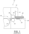
- a converting, or finishing machine 12 e.g., as illustrated diagrammatically in the side view of Fig. 1 .
- blank sheets 14 are fed from a hopper 16 through the feed end section 10 into following conventional finishing machine sections 18.
- the feeding process typically uses a lead edge feeder 20 incorporating a set of feeder wheels 22 which deliver sheets 14 one at a time into a nip 30 between an upper elastomer covered feed roll 32 and a lower knurled steel feed roll 34.
- the rolls 32 and 34 comprise a feed/pull set generally indicated at 36, with the elastomer feed/pull roll 32 in particular being the focus of this invention.
- the function of the feed/pull roll set 36 is to grip a sheet 14 in the nip 30 with sufficient force to pull it out from the bottom of a stack 40 in hopper 16 after the lead edge feeder 20 and feeder wheels 22 initiate the feed, to accelerate the sheet to machine speed, and then to traverse it through the feed/pull roll nip 30, and in some cases a distance beyond the feed/pull roll nip.
- the feed/pull roll set 36 continues to transfer the sheet at machine speed to the next hand-off point in the following machine section 18, which may be a vacuum transfer unit, a print / impression nip, or a pull roll set nip as is conventional.
- the upper and lower feed/pull roll set, or combination 36 is adjustably secured in the converting or finishing machine 12 to allow adjustment of the distance between the rolls 30 and 32R.
- This distance or opening (gap) between the rolls forms the nip 30, which spans the length of the rolls and thus the lateral width of the path of the sheet 14.
- the gap is set to be slightly less than the caliper or thickness of the sheet or board 14 that is being processed so as to grip the sheet but not crush it.
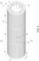
- Improved Feed Roll Assembly 32R consists of a cylindrical core roll 50 and one or more detachable elongated feed cover sections, three of which are generally indicated at 52, 54 and 56, each of which wraps circumferentially about the cylindrical outer surface 60 of, and is secured to, the core 50.
- the feed/pull roll assembly 32R of the invention may be a replacement for currently-used original equipment rolls in a finishing machine, wherein the original feed roll (e.g., prior art roll 32) is constructed of a core roll with a elastomer layer bonded to its outer surface, or may be itself original equipment for new finishing machines.
- the core 50 of the roll 32R according to the invention is a cylindrical steel roll of a length and diameter based on the size and width of the finishing machine 12. If the roll 32R is a replacement it will have a core diameter that is approximately 1 .00" (25.4mm) less than the design diameter of the original equipment elastomer roll 32 which it is to replace in the assembled feed/pull roll set 36.
- This smaller diameter is provided to accommodate the thickness of the replaceable feed cover sections (e.g., as illustrated in Figs 9A-9H ) which will be used instead of the prior elastomer covering. If the improved elastomer covered feed roll assembly 32R of the present invention is original equipment, it will have the appropriate length and diameter for the machine design.
- the roll core 50 carries a plurality of feed roll cover sections, three of which are illustrated in the sectional view of Fig. 2 at 52, 54 and 56 and which wrap around the outer circumference 60 of the roll core. Although three are illustrated, it will be understood that additional feed roll cover sections may be positioned in close side-by-side relationship along the length of the core 50, with one embodiment, to be discussed below, including 11-13 cover sections.
- Each cover section is generally rectangular, having inner and outer surfaces 62 and 64, opposite sides 66 and 68 defining the width W of the cover section, and opposite ends 70 and 72 defining the circumferential length L of the cover section (see Fig. 8 ).
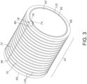
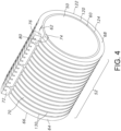
- cover section 52 When a cover section such as section 52 is being installed on the core 50, as illustrated in Fig. 4 and when on the core as illustrated in Figs. 2 and 3 , the inner surface 62 of the cover section is placed in contact with the outer surface 60 of the cylindrical core 50 and the section is wrapped around the core.
- the circumferential length of the cover section 52 is of sufficient length to bring the opposite ends 70 and 72 into abutment with each other, as illustrated in Figs 2 , 3 , 4 and 6 .
- the side walls 66 and 68 extend circumferentially around the cylindrical roll 50, and the abutting end walls extend longitudinally along the roll, parallel to the axial length of the roll.
- the opposite ends 70 and 72, respectively, of the roll cover section 52 incorporate first and second locking shoulder components 74 and 76 of a locking mechanism generally indicated at 78 (see, e.g., Figs. 3 and 4 ).
- the locking mechanism for feed cover section 52 is secured in a corresponding longitudinally extending slot, or keyway 80.
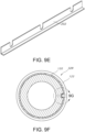
- each cover section is secured in a corresponding keyway, such as the elongated keyways 80, 82, 84 and 86 illustrated in Fig 6 .
- These keyways may be machined or otherwise formed in the outer cylindrical surface 60 of roll core 50 in a longitudinal (or axially aligned) direction, parallel to the central axis of the core 50, and are configured as locking slots for receiving corresponding cover section locking mechanisms.
- three cover sections and four keyways are herein illustrated, it will be understood that a corresponding keyway is provided for each feed cover section mounted on a given improved elastomer covered feed roll assembly 32R.
- each keyway is longitudinally spaced, as indicated at 90, with adjacent keyways being on approximately 10.00" (254mm) centers along the length of the roll 50 in one embodiment of the invention.
- the keyways are circumferentially, or angularly, offset around the roll, as indicated at 92 in Fig. 6 ; that is, each keyway is offset around the circumference of the roll with respect to adjacent keyways, as illustrated.
- the axial length 94 of each keyway is substantially equal to the width of its corresponding feed cover section and to the axial length of the locking mechanism 78 mounted across the width of the cover section that it is to receive.
- the keyways are 10" (254mm) long, with the keyways being equally spaced along the length of the roll core so as to position the corresponding feed cover sections in side-by-side abutting relationship, as illustrated in Fig. 2 with the side wall 68 of one cover section abutting the sidewall 66 of the next adjacent cover section.
- a small gap or axial spacing between adjacent replaceable flexible feed cover sections may be provided. The angular spacing, or offset, of the keyways around the circumference of the roll core causes the feed cover section end joints, indicated in Fig.
- the longitudinal spacing and circumferential offset provide a keyway pattern that is symmetrical about the roll centerline or axis 110 to balance the roll and reduce the effect of the keyways on roll rotation.
- a 7.00" (177.8mm) diameter improved elastomer covered feed roll assembly 32R may be 110" (9427mm) in length, and may carry eleven keyways each 10" (254mm) in length and spaced 10" (254mm) on center along the length of the roll core to receive and secure eleven feed cover sections each having a width (or axial dimension) of 10.00" (254mm).
- the preferred elastomer gripping surface or cover material for improved elastomer covered feed roll assembly 32R is preferably a rubber-like composition which, in its finished cured state provides a tough, resilient durable gripping surface having a durometer in the range of 25 to 35, and preferably 30.
- the elastomeric coating or layer 122 for the feed cover may be molded-in situ onto the flexible backing member 120, or may cast and then bonded to the flexible backing member 120, either with the textured surface and grooves 130.
- the elastomeric coating or layer (122) may be molded in situ or cast and bonded and then the grooves 130 and surface texture may be added by shaping, cutting or machining processes.
- the elastomeric coating or layer 122 is a tough, durable material, but with continuous operation, over time, the abrasiveness of corrugated boards 14 causes eventual wear of the elastomer gripping surface. Because finishing machines are typically center-justified so that each sheet being fed is centered on the feed/pull roll set 36, the center section of the feed/pull roll set is always in contact with the corrugated sheet, regardless of the width of the board being fed, while end sections of the set may be used less often, for example only for wider sheets. As a result, the center section of the elastomer gripping surface wears first, with progressively less wear towards the ends of the roll.
- the roll set starts to exhibit a longitudinal concave profile, with the spacing between the rolls 32 and 34, for example, becoming greater at the center than at the ends (as noted above).
- the gripping force generated by the nip pressure of the feed/pull roll set starts to diminish at the center, resulting in uneven forces on the sheets being fed, and in the method of the present invention that center section's wear is identified for subsequent repair or refurbishment.
- the elastomer feed roll cover should be changed to maintain optimum performance.
- the difficulty and expense of refurbishing a feed roll cover led, in many cases, to operators simply reducing the set-up opening (gap) to increase impression so as to continue production, resulting in poor feeding, excessive crush, and/or poor registration.
- the replaceable cover system eliminates the need to remove the entire roll (e.g., 36) from the machine (e.g., 12) and eliminates the associated costs of that sort of removal and refurbishment.
- the scheduling time for maintenance is reduced from days to minutes so the finishing machine operator can be more responsive to roll performance degradation to maintain proper machine performance.
- each feed cover section such as the feed cover section 52 shown in Figs. 3 and 4 , consists of elongated inner support member or substrate 120 made of a thin flexible material such as steel (e.g., ⁇ 0.018" (0.04572mm) thick) or a polymer mesh.
- the support member or feed roll cover backing 120 preferably is approximately 10.00" (25.4mm) in width between the cover section side edges 66 and 68 and is long enough to reach around the circumference of the roll core 50 with its ends abutting at joint 96 ( Fig. 3 ) when installed.
- a grooved elastomeric (preferably nitrile rubber or urethane) layer 122 approximately 0.50" (1.27mm) in thickness is preferably molded upon or cast onto and permanently applied or bonded onto outer surface 124 of the inner support member 120 using best practices for elastomer molding/manufacturing.
- the elastomer is cast, molded or shaped to the desired finished thickness or is molded or cast to be over-size and is shaped or machined to the finished thickness and texture.
- elastomeric layer 122 may be fabricated from cut sheets of Sheet Rubber material made from EPDM Rubber, Natural Gum Rubber, Neoprene Rubber, Nitrile Rubber, Recycled Rubber, Silicone Rubber or Synthetic Rubber.
- nitrile rubber is a mixture of components which is cured in an autoclave to achieve a selected hardness (e.g., Shore A durometer hardness) of e.g. 35 after curing, so a finished elastomeric layer 122 is preferably 30 +/- 5 (Shore A).
- Shore A durometer hardness e.g. 35 after curing
- a finished elastomeric layer 122 is preferably 30 +/- 5 (Shore A).
- Softer and harder nitrile rubber materials are available (e.g., 25, 45, 55, 70 Shore A) and these could applied on a roll as a single durometer or as a dual durometer layers (with, e.g. dual durometer layers of 25/55 or 35/55).
- the opposing ends 70 and 72 of the feed cover sections are all fitted with suitable locking mechanisms 78 each incorporating components 64, 66 on the opposing ends of the section.
- These components may be conventional inner and outer lock members or male and female lock members.
- the locking mechanism fits into its corresponding roll core keyway as diagrammatically illustrated in Figs. 3 and 4 to secure the feed cover section onto the roll core surface so that the roll core and the feed covers will rotate as one system.
- the lock may use suitable hardware to assure a secure mechanical connection within the roll core keyway.
- each feed cover section may comprise at a first end a slotted clamp bar 202 and at a second end a clamp bar 203 configured to cooperate with the slotted clamp bar 202 and receive first and second bolts or threaded fasteners which are threadably received in threaded bores in the roll core's locking slot (e.g., 80, 82, 84, 86) each corresponding to the feed cover section to mount and removably secure each feed cover section on the surface of the roll core, with each of the keyways drawing together the opposite ends (70, 72) of its corresponding cover section to form an end joint (96), the keyways being spaced (90) along the length of the roll core to mount the identified, selected replacement feed cover sections in side-by-side abutting relationship on the roll core and being circumferentially offset (92) to space the end joints around the circumference of the roll core.
- first and second bolts or threaded fasteners which are threadably received in threaded bores in the roll core's locking slot (e.g., 80
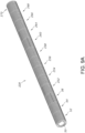
- Figs 9A and 9B illustrate an improved feed roll assembly 32R including thirteen (13) feed cover segments (e.g., 52, 54, 56, 252, 254, 256, 258, 260, 262, 264, 266, 268, 270), in accordance with the present invention.
- feed cover segments e.g., 52, 54, 56, 252, 254, 256, 258, 260, 262, 264, 266, 268, 270
- Longitudinal feed grooves 130 extend along the length of the external gripping surface of each replaceable flexible feed cover section (e.g., 52), in compliance with feed/pull roll standards, and extend circumferentially around the improved elastomer covered feed roll assembly 32R when the cover sections are installed on the roll core 50, as illustrated in the Figures.
- These gripping slots or grooves are either formed during the elastomer gripping surface molding or casting process or are machined or shaped into the elastomer gripping surface after formation of the cover.
- a cover section e.g., 52
- the opposite ends of the cover abut at 96 to form a joint extending across the width of the cover and extend in a direction lengthwise, or axially, along the improved elastomer covered feed roll assembly 32R, as illustrated.
- the end joint for each cover marks the location of its corresponding keyway, and thus the joints in adjacent covers are circumferentially offset, as illustrated at joints 96, 98 and 100 in Fig. 2 .
- the feed cover sections e.g., 52, 54, 56, etc.
- the advantages and benefits of the improved elastomer covered feed roll assembly 32R of the present invention, and of the process for refurbishing feed/pull rollers include:
- a machine owner/customer ships a used roll (e.g., 32) that is to be refurbished to the roll manufacturer or supplier, who will inspect the roll to assure it is in good condition. Once a satisfactory condition is established, the roll is stripped of the worn elastomer surface, cleaned, and turned to a specific diameter if necessary.
- Keyways e.g., 80, 82, 84 are milled in the specific locations required for installation of the replaceable flexible feed cover sections of the invention, and the roll is then fitted with a complete set of feed cover sections to provide an improved elastomer covered feed roll assembly 32R, where the number of replaceable flexible feed cover sections (e.g., 52) will depend on the roller dimensions. If the customer does not have a used roll to use as a core, a new roll will be produced to the specifications referenced above. At an opportune time, the customer then swaps out the worn elastomer feed roll 32 and installs the new improved elastomer covered feed roll assembly 32R of the present invention.
- the elastomer gripping surface can be examined, and if excess wear is discovered or identified, selected sections can be easily refurbished or completely replaced simply by changing out selected replaceable flexible feed cover sections, or all of the replaceable flexible feed cover sections, as needed.
- replaceable flexible feed cover sections e.g., 52 on improved elastomer covered feed roll assembly 32R are affixed in place with threaded fasteners (see e.g., Fig. 9H ) and they are flexible, so they can be removed by removing the outer locking hardware (e.g., such as bolts or threaded fasteners 250) prying the outer locking component of the lock mechanism from the inner locking component (similar to an anvil cover), then removing the hardware from the inner locking component.
- the replaceable flexible feed cover section can then be pulled off the core.
- Each replaceable flexible feed cover section to be replaced can then be successively removed in the same manner.
- a new set of replaceable flexible feed cover sections is installed in opposite steps, i.e., a feed-cover is wrapped or threaded around the roll core 50, the inner locking component is inserted in the keyway, a fastener locks it in place, and the outer locking component is forced into the keyway creating an interference fit, and two fasteners 250 are then used to lock the feed cover section (e.g., 52) in place.
- Each successive replaceable flexible feed cover section is installed in the same manner. Other locking arrangements are possible.
- Figs 1 (for context) and 2-9H provides an improved repair refurbishing method for retrofitting an improved elastomer covered feed roll assembly 32R onto a machine (e.g., 12) with a feed/pull roll set (e.g., 36) where operators have operated the feed/pull roll set (36) for an operation interval having a duration long enough to cause significant wear to the elastomer gripping surface of one or more replaceable flexible feed cover sections in an identified section (e.g., the center) of the improved elastomer covered feed roll assembly 32R.
- a machine e.g., 12
- a feed/pull roll set e.g., 36
- operators have operated the feed/pull roll set (36) for an operation interval having a duration long enough to cause significant wear to the elastomer gripping surface of one or more replaceable flexible feed cover sections in an identified section (e.g., the center) of the improved elastomer covered feed roll assembly 32R.
- the operator or machine owner identifies the replaceable flexible feed cover sections which have accrued the excessive wear and selects the identified worn replaceable flexible feed cover sections and then, using the process described and illustrated above, removes those worn replaceable flexible feed cover sections from the identified worn area (e.g., the center the roll core 50). The user or operator may then replace the selected identified worn replaceable flexible feed cover sections with an equal number of new, replacement flexible feed cover sections (e.g., 52).
- this refurbishment method can include removably mounting the new, replacement flexible feed cover sections on the roll core 50 by locking the locking components (74, 76) on opposite ends (70, 72) of each new replaceable flexible feed cover sections.
- Those locking components of each replaceable flexible feed cover section are aligned with and then engaged within a locking slot (80, 82, 84, 86) corresponding to the replaceable flexible feed cover section and the keyways draw together the opposite ends (70, 72) of corresponding replaceable flexible feed cover section sections to form very small, operationally negligible end joints (96, 98, 100) to provide a refurbished surface that appears to be a substantially contiguous elastomer gripping surface.
- each replaceable flexible feed cover section comprise at a first end a slotted clamp bar 202 and at a second end a clamp bar 203 configured to cooperate with the slotted clamp bar 202 which receive first and second bolts or threaded fasteners and the mounting step comprises threadably fastening the slotted clamp bar 202 and clamp bar 203 to aligned threaded bores in the roll core's locking slot (as best seen in Fig.
- the improved elastomer covered feed roll assembly 32R has, effectively, the same feeding performance as a feed roll with a one piece elastomeric roll cover (e.g., prior art elastomer covered feed roll 32).
Landscapes
- Engineering & Computer Science (AREA)
- Mechanical Engineering (AREA)
- Rolls And Other Rotary Bodies (AREA)
- Delivering By Means Of Belts And Rollers (AREA)
- Sheets, Magazines, And Separation Thereof (AREA)
Claims (10)
- Eine verbesserte, mit Elastomer beschichtete Zuführungs- bzw. Vorschubwalzenanordnung (32R), die Folgendes aufweist:einen Walzenkern (50) mit einer zylindrischen Oberfläche (60) mit mindestens einer sich in Längsrichtung erstreckenden Keilnut (80), die als Verriegelungsschlitz konfiguriert ist;mindestens einen ersten austauschbaren flexiblen Zuführungsabdeckungsabschnitt (52), der eine flexible Unterlage (120) aufweist, die eine elastomere Beschichtung oder Schicht (122) trägt, die eine elastomere Greiffläche definiert; underste und zweite Verriegelungskomponenten (74, 76) an gegenüberliegenden Enden (70, 72) des austauschbaren flexiblen Zuführungsabdeckungsabschnitts, die so konfiguriert sind, dass sie lösbar an einem entsprechenden Verriegelungsschlitz befestigt sind und in diesen eingreifen, um den austauschbaren flexiblen Zuführungsabdeckungsabschnitt (52) an der zylindrischen Oberfläche (60) des Walzenkerns (50) zu montieren und abnehmbar zu befestigen;dadurch gekennzeichnet, dassder Walzenkern eine Vielzahl von in Längsrichtung beabstandeten und in Umfangsrichtung versetzten Verriegelungsschlitzen (80, 82, 84) zum Anbringen und Befestigen einer entsprechenden Vielzahl von nebeneinander angeordneten, austauschbaren, flexiblen Zuführungsabdeckungsabschnitten (52, 54, 56) auf dem Walzenkern aufweist.
- Die verbesserte, mit Elastomer beschichtete Zuführungswalzenanordnung (32R) nach Anspruch 1, wobei jeder austauschbare flexible Zuführungsabdeckungsabschnitt mehrere Zuführungsnuten (130) aufweist, die sich zwischen den Enden (70, 72) und entlang der Länge des Zuführungsabdeckungsabschnitts erstrecken und die die Zuführungswalze umschließen, wenn sie montiert ist.
- Die verbesserte, mit Elastomer beschichtete Zuführungswalzenanordnung (32R) nach Anspruch 2, wobei die Elastomerbeschichtung oder -schicht (122) für die Zuführungsabdeckung in situ geformt, gegossen oder aus einem Sheet geschnitten und dann gebondet bzw. verklebt wird, oder wobei sie ein geformtes Elastomer ist, das aus einem haltbaren Elastomer wie einem synthetischen Gummi, z.B. Nitrilkautschuk, mit einer Durometer-Härte im Bereich von 25 bis 35, vorzugsweise 30, hergestellt ist.
- Eine verbesserte, mit Elastomer beschichtete Zuführungs- bzw. Vorschubwalzenanordnung (32R) zur Verwendung in einer Zuführungs- bzw. Vorschub-/Zugwalzensatz-Kombination (36) in einer Sheetveredelungsmaschine (12), wobei die Zuführungswalzenanordnung Folgendes aufweist:einen Walzenkern (50) mit einer zylindrischen Oberfläche (60), die mehrere in Längsrichtung beabstandete und in Umfangsrichtung versetzte längliche Keilnuten (80, 82, 84, 86) aufweist, die jeweils als Verriegelungsschlitz ausgebildet sind;mehrere austauschbare flexible Zuführungsabdeckungsabschnitte (52, 54, 56), die jeweils eine flexible Unterlage oder Substrat (120) und eine elastomere Schicht oder Beschichtung (122) enthalten; underste und zweite Verriegelungskomponenten (74, 76) an gegenüberliegenden Enden (70, 72) jedes der austauschbaren flexiblen Zuführungsabdeckungsabschnitte, wobei die Verriegelungskomponenten jedes austauschbaren flexiblen Zuführungsabdeckungsabschnitts in einen Verriegelungsschlitz (80, 82, 84, 86) eingreifen, der dem austauschbaren flexiblen Zuführungsabdeckungsabschnitt entspricht, um jeden austauschbaren flexiblen Zuführungsabdeckungsabschnitt auf der Oberfläche des Walzenkerns zu befestigen und abnehmbar zu sichern, wobei jede der Keilnuten die gegenüberliegenden Enden (70, 72) ihres entsprechenden austauschbaren flexiblen Abdeckabschnitts zusammenzieht, um eine Endverbindung (96) zu bilden, wobei die Keilnuten (90) entlang der Länge des Walzenkerns beabstandet sind, um die austauschbaren flexiblen Zuführungsabdeckungsabschnitte in einer Seite-an-Seite-Angrenzbeziehung auf dem Walzenkern zu montieren, und in Umfangsrichtung versetzt (92) sind, um die Endverbindungen um den Umfang des Walzenkerns herum zu beabstanden.
- Die verbesserte, mit Elastomer beschichtete Zuführungswalzenanordnung (32R) nach Anspruch 4, wobei jeder austauschbare flexible Zuführungsabdeckungsabschnitt eine Breite (W) aufweist, die im Wesentlichen der Länge (94) seiner entsprechenden Keilnut entspricht, und eine Länge (L), die ausreicht, um den Umfang des Walzenkerns zu umschließen, wobei die flexible Unterlage oder das flexible Substrat ein längliches inneres Stützelement (20) aus einem flexiblen Material, und zwar einschließlich, aber nicht beschränkt auf dünnen Stahl, z.B. 0,018" (0,04572 mm) dick, oder Polymergewebe aufweist, und wobei der austauschbare flexible Zuführungsabdeckungsabschnitt eine dünne Elastomerbeschichtung oder -schicht (122) auf der Außenfläche (124) des inneren Stützelements (120) aufweist.
- Ein Verfahren zum Aufarbeiten eines Vorschub-/Zugwalzensatzes (36) in einer Veredelungsmaschine (12), der eine Zuführungs- bzw. Vorschubwalze (32) mit einem Walzenkern (50) aufweist, der mit einer Elastomerbeschichtung bedeckt ist, wobei das Verfahren Folgendes aufweist:(a) Entfernen der Zuführungswalze (32) aus der Maschine;(b) Abziehen der Elastomerbeschichtung vom Walzenkern;(c) Reinigen des Walzenkerns;(d) Ausbilden einer Vielzahl von sich in Längsrichtung erstreckenden, in Umfangsrichtung versetzten Verriegelungskeilnuten (80, 82, 84, 86) auf dem Walzenkern;(e) Bereitstellen einer Vielzahl von austauschbaren flexiblen Zuführungsabdeckungsabschnitten (52, 54, 56) mit einer flexiblen Unterlage (120) und einer Elastomerbeschichtung oder -schicht (122), und mit einem Verriegelungsmechanismus (74, 76) an jeweiligen Enden (70, 72) jeder Abdeckung;(f) Installieren der austauschbaren flexiblen Zuführungsabdeckungsabschnitte auf dem Walzenkern, wobei die Verriegelungsmechanismen für jede Abdeckung in entsprechende Keilnuten eingreifen, um die Zuführungsabdeckungen in einer Seite-an-Seite-Angrenzbeziehung auf der Rollenabdeckung lösbar zu befestigen; und(g) Ersetzen der aufgearbeiteten Zuführungswalze mit den Zuführungsabdeckungen in der Maschine, wodurch eine zukünftige Aufarbeitung der Zuführungswalze durch Ersetzen ausgewählter abnehmbarer, austauschbarer, flexibler Zuführungsabdeckungsabschnitte erreicht wird, um eine im Wesentlichen durchgehende, verbesserte oder aufgearbeitete, "wie neu" Elastomer-Greifoberfläche bereitzustellen, die durch die angrenzenden austauschbaren, flexiblen Zuführungsabdeckungsabschnitte definiert ist.
- Das Verfahren zum Aufarbeiten zum Aufarbeiten nach Anspruch 6, wobei Schritt (f) Folgendes aufweist:austauschbar Montieren der abnehmbaren, austauschbaren, flexiblen Zuführungsabdeckungsabschnitte auf dem Walzenkern, indem die Verriegelungskomponenten (74, 76) an gegenüberliegenden Enden (70, 72) jedes der austauschbaren, flexiblen Zuführungsabdeckungsabschnitte verriegelt werden;wobei die Verriegelungskomponenten jedes austauschbaren flexiblen Zuführungsabdeckungsabschnitts in einen Verriegelungsschlitz (80, 82, 84, 86) eingreifen, der dem austauschbaren flexiblen Zuführungsabdeckungsabschnitt entspricht; undwobei die Keilnuten die gegenüberliegenden Enden (70, 72) entsprechender austauschbarer flexibler Zuführungsabdeckungsabschnitte zusammenziehen, um entsprechende Endverbindungen (96, 98, 100) zu bilden.
- Das Verfahren zum Aufarbeiten nach Anspruch 6, das ferner Folgendes aufweist:(h) Betreiben des Vorschub-/Zugwalzensatzes (36) für ein Betriebsintervall, das eine ausreichende Länge aufweist, um eine erhebliche Abnutzung der Elastomergreiffläche eines oder mehrerer austauschbarer flexibler Zuführungsabdeckungsabschnitte in einem identifizierten Abschnitt (z.B. der Mitte) der verbesserten elastomerbeschichteten Zuführungswalzenanordnung (32R) zu verursachen;(i) Identifizieren der austauschbaren flexiblen Zuführungsabdeckungsabschnitte, die übermäßig abgenutzt worden sind;(j) Auswählen der identifizierten abgenutzten austauschbaren flexiblen Zuführungsabdeckungsabschnitte und Entfernen dieser abgenutzten austauschbaren flexiblen Zuführungsabdeckungsabschnitte vom Walzenkern (50); und(k) Ersetzen der ausgewählten identifizierten abgenutzten austauschbaren flexiblen Zuführungsabdeckungsabschnitte durch eine gleiche Anzahl neuer austauschbarer flexibler Zuführungsabdeckungsabschnitte (z B. 52).
- Das Verfahren zum Aufarbeiten nach Anspruch 6, das ferner Folgendes aufweist:austauschbar Montieren der neuen, austauschbaren flexiblen Zuführungsabdeckungsabschnitte auf dem Walzenkern (50) durch Verriegeln der Verriegelungskomponenten (74, 76) an gegenüberliegenden Enden (70, 72) jedes der neuen austauschbaren flexiblen Zuführungsabdeckungsabschnitte;wobei die Verriegelungskomponenten jedes austauschbaren flexiblen Zuführungsabdeckungsabschnitts in einen Verriegelungsschlitz (80, 82, 84, 86) eingreifen, der dem austauschbaren flexiblen Zuführungsabdeckungsabschnitt entspricht; und wobeidie Keilnuten die gegenüberliegenden Enden (70, 72) entsprechender austauschbarer flexibler Zuführungsabdeckungsabschnittsabschnitte zusammenziehen, um entsprechende Endverbindungen (96, 98, 100) zu bilden.
- Das Verfahren zum Aufarbeiten nach Anspruch 9, wobei die Verriegelungskomponenten (74, 76) jedes austauschbaren flexiblen Zuführungsabdeckungsabschnitts an einem ersten Ende eine geschlitzte Klemmleiste (202) und an einem zweiten Ende eine Klemmleiste (203) aufweisen, die so konfiguriert ist, dass sie mit der geschlitzten Klemmleiste (202) zusammenwirkt und erste und zweite Bolzen oder Gewindebefestigungselemente aufnimmt, und wobei der Montageschritt gewindemäßiges Befestigen der geschlitzten Klemmleiste (202) und der Klemmleiste (203) in Gewindebohrungen in dem Verriegelungsschlitz (80, 82, 84, 86) des Walzenkerns aufweist, die dem austauschbaren flexiblen Zuführungsabdeckungsabschnitt entsprechen, um jeden Zuführungsabdeckungsabschnitt auf der Oberfläche des Walzenkerns zu montieren und abnehmbar zu befestigen, wobei jede der Keilnuten die gegenüberliegenden Enden (70, 72) des entsprechenden Abdeckabschnitts zusammenziehen, um eine Endverbindung (96) zu bilden, wobei die Keilnuten entlang der Länge des Walzenkerns beabstandet (90) sind, um die identifizierten, ausgewählten Ersatz-Zuführungsabdeckungsabschnitte in einer Seite-an-Seite-Angrenzbeziehung auf dem Walzenkern zu montieren, und in Umfangsrichtung versetzt (92) sind, um die Endverbindungen um den Umfang des Walzenkerns herum zu beabstanden.
Applications Claiming Priority (2)
| Application Number | Priority Date | Filing Date | Title |
|---|---|---|---|
| US201662327840P | 2016-04-26 | 2016-04-26 | |
| PCT/US2017/029657 WO2017189737A1 (en) | 2016-04-26 | 2017-04-26 | Feed/pull roll system with detachable elastomeric feed-covers, and process for cover replacement |
Publications (3)
| Publication Number | Publication Date |
|---|---|
| EP3448787A1 EP3448787A1 (de) | 2019-03-06 |
| EP3448787A4 EP3448787A4 (de) | 2020-11-04 |
| EP3448787B1 true EP3448787B1 (de) | 2025-01-08 |
Family
ID=60160066
Family Applications (1)
| Application Number | Title | Priority Date | Filing Date |
|---|---|---|---|
| EP17790352.3A Active EP3448787B1 (de) | 2016-04-26 | 2017-04-26 | Förder-/ziehrollsystem mit abnehmbaren elastomeren zuführabdeckungen und verfahren zum ersetzen der abdeckungen |
Country Status (6)
| Country | Link |
|---|---|
| US (1) | US11274004B2 (de) |
| EP (1) | EP3448787B1 (de) |
| JP (1) | JP7150612B2 (de) |
| CN (1) | CN109689540B (de) |
| CA (1) | CA3022326A1 (de) |
| WO (1) | WO2017189737A1 (de) |
Families Citing this family (1)
| Publication number | Priority date | Publication date | Assignee | Title |
|---|---|---|---|---|
| CN116619208B (zh) * | 2023-04-26 | 2026-03-31 | 浙江铭凯集成房屋股份有限公司 | 一种彩钢板加工打磨清洗装置 |
Family Cites Families (13)
| Publication number | Priority date | Publication date | Assignee | Title |
|---|---|---|---|---|
| US3537632A (en) * | 1968-07-03 | 1970-11-03 | Ward Turner Machinery Co | Detachable cover for a pull roll or collar |
| US3964658A (en) * | 1974-09-04 | 1976-06-22 | Edwards Edwin L | Roller replacing |
| JPS5747159Y2 (de) * | 1978-10-30 | 1982-10-16 | ||
| JPS56126399U (de) * | 1980-12-26 | 1981-09-25 | ||
| US4378737A (en) * | 1981-06-01 | 1983-04-05 | Robud Company | Roller apparatus with replacement blanket |
| US4566162A (en) * | 1982-10-26 | 1986-01-28 | American Roller Company | Stretcher/expander roller |
| JPS6390652U (de) * | 1986-12-02 | 1988-06-13 | ||
| US5720212A (en) * | 1995-03-22 | 1998-02-24 | Robud | Locking arrangement for die cutter blanket |
| US6435069B1 (en) * | 1999-11-23 | 2002-08-20 | Iam Corporation | Rotary die cutting cover |
| US6612214B2 (en) * | 2001-10-05 | 2003-09-02 | Robud | Die cutter blanket-anvil locking arrangement |
| US6820529B2 (en) * | 2002-06-03 | 2004-11-23 | Day International, Inc. | Cutting mat |
| JP2005162350A (ja) * | 2003-11-28 | 2005-06-23 | Sumitomo Rubber Ind Ltd | 紙送り用ゴムローラおよびその製造方法 |
| CN201989343U (zh) * | 2011-04-01 | 2011-09-28 | 群烨实业有限公司 | 纸箱制作机前端送纸轮 |
-
2017
- 2017-04-26 EP EP17790352.3A patent/EP3448787B1/de active Active
- 2017-04-26 US US16/096,218 patent/US11274004B2/en active Active
- 2017-04-26 CN CN201780035677.0A patent/CN109689540B/zh active Active
- 2017-04-26 WO PCT/US2017/029657 patent/WO2017189737A1/en not_active Ceased
- 2017-04-26 CA CA3022326A patent/CA3022326A1/en active Pending
- 2017-04-26 JP JP2018555918A patent/JP7150612B2/ja active Active
Also Published As
| Publication number | Publication date |
|---|---|
| US20190218039A1 (en) | 2019-07-18 |
| JP2019514815A (ja) | 2019-06-06 |
| JP7150612B2 (ja) | 2022-10-11 |
| CA3022326A1 (en) | 2017-11-02 |
| CN109689540B (zh) | 2021-12-17 |
| EP3448787A1 (de) | 2019-03-06 |
| US11274004B2 (en) | 2022-03-15 |
| EP3448787A4 (de) | 2020-11-04 |
| WO2017189737A1 (en) | 2017-11-02 |
| CN109689540A (zh) | 2019-04-26 |
Similar Documents
| Publication | Publication Date | Title |
|---|---|---|
| KR101419714B1 (ko) | 골판지 인쇄기용 급지 롤러 | |
| US11274004B2 (en) | Feed pull roll system with detachable elastomeric feed-roll covers and process for cover replacement | |
| US8677899B2 (en) | Reversible anti-marking jackets and methods of using | |
| KR100982410B1 (ko) | 후렉소드럼 인쇄기용 로터리 커터장치 | |
| US20250296797A1 (en) | Primer apparatus | |
| CN108116039B (zh) | 印刷机 | |
| JP5201914B2 (ja) | 段ボールシートの罫線形成装置及び段ボールシート用製函機 | |
| US7476191B2 (en) | Die cutting/scoring apparatus sheet material driving member | |
| US20210053087A1 (en) | Adhesive application roller | |
| TW201408565A (zh) | 用於處理板件之具有運輸裝置之餽送桌的機器 | |
| US6412383B1 (en) | Device for cross cutting material webs | |
| JP4787591B2 (ja) | ナイフ受けロール及びシート切断装置並びにスリッタスコアラ | |
| KR20140090580A (ko) | 골판지 인쇄기용 급지 롤러 | |
| JP5843435B2 (ja) | 印刷胴、印刷ユニット、印刷機並びに印刷胴の製造方法 | |
| KR101375129B1 (ko) | 골판지 인쇄기용 급지 롤러 | |
| KR102245464B1 (ko) | 모듈형 탄성롤 | |
| JP2002274671A (ja) | 印刷機,製函機に使われている、紙、シートの送り用コロ。 | |
| RU2780783C2 (ru) | Способ нанесения узора клея на лист материала с применением блока для нанесения клея и блок для нанесения клея | |
| US20230174334A1 (en) | Flexible jacket with ink marking zone identification indicator | |
| WO2000051771A1 (en) | A method and apparatus for slitting strip | |
| JPH0544353Y2 (de) | ||
| EP2202068B1 (de) | Schnellspann- und Schnelllöseschutzring für Druckhülsen | |
| KR200411992Y1 (ko) | 마그네틱 실린더를 갖는 라벨 인쇄기 | |
| US20090052816A1 (en) | Wear pads for head yoke plates | |
| KR100669894B1 (ko) | 마그네틱 실린더를 갖는 라벨 인쇄기 |
Legal Events
| Date | Code | Title | Description |
|---|---|---|---|
| STAA | Information on the status of an ep patent application or granted ep patent |
Free format text: STATUS: THE INTERNATIONAL PUBLICATION HAS BEEN MADE |
|
| PUAI | Public reference made under article 153(3) epc to a published international application that has entered the european phase |
Free format text: ORIGINAL CODE: 0009012 |
|
| STAA | Information on the status of an ep patent application or granted ep patent |
Free format text: STATUS: REQUEST FOR EXAMINATION WAS MADE |
|
| 17P | Request for examination filed |
Effective date: 20181101 |
|
| AK | Designated contracting states |
Kind code of ref document: A1 Designated state(s): AL AT BE BG CH CY CZ DE DK EE ES FI FR GB GR HR HU IE IS IT LI LT LU LV MC MK MT NL NO PL PT RO RS SE SI SK SM TR |
|
| AX | Request for extension of the european patent |
Extension state: BA ME |
|
| DAV | Request for validation of the european patent (deleted) | ||
| DAX | Request for extension of the european patent (deleted) | ||
| RIC1 | Information provided on ipc code assigned before grant |
Ipc: B65H 27/00 20060101ALI20191118BHEP Ipc: B65H 3/06 20060101ALI20191118BHEP Ipc: B65G 47/00 20060101AFI20191118BHEP Ipc: B65H 5/06 20060101ALI20191118BHEP |
|
| A4 | Supplementary search report drawn up and despatched |
Effective date: 20201007 |
|
| RIC1 | Information provided on ipc code assigned before grant |
Ipc: B65G 47/00 20060101AFI20201001BHEP Ipc: B65H 3/06 20060101ALI20201001BHEP Ipc: B65H 27/00 20060101ALI20201001BHEP Ipc: B65H 5/06 20060101ALI20201001BHEP |
|
| STAA | Information on the status of an ep patent application or granted ep patent |
Free format text: STATUS: EXAMINATION IS IN PROGRESS |
|
| 17Q | First examination report despatched |
Effective date: 20230915 |
|
| GRAP | Despatch of communication of intention to grant a patent |
Free format text: ORIGINAL CODE: EPIDOSNIGR1 |
|
| STAA | Information on the status of an ep patent application or granted ep patent |
Free format text: STATUS: GRANT OF PATENT IS INTENDED |
|
| INTG | Intention to grant announced |
Effective date: 20240320 |
|
| GRAJ | Information related to disapproval of communication of intention to grant by the applicant or resumption of examination proceedings by the epo deleted |
Free format text: ORIGINAL CODE: EPIDOSDIGR1 |
|
| STAA | Information on the status of an ep patent application or granted ep patent |
Free format text: STATUS: EXAMINATION IS IN PROGRESS |
|
| INTC | Intention to grant announced (deleted) | ||
| GRAP | Despatch of communication of intention to grant a patent |
Free format text: ORIGINAL CODE: EPIDOSNIGR1 |
|
| STAA | Information on the status of an ep patent application or granted ep patent |
Free format text: STATUS: GRANT OF PATENT IS INTENDED |
|
| INTG | Intention to grant announced |
Effective date: 20240806 |
|
| GRAS | Grant fee paid |
Free format text: ORIGINAL CODE: EPIDOSNIGR3 |
|
| GRAA | (expected) grant |
Free format text: ORIGINAL CODE: 0009210 |
|
| STAA | Information on the status of an ep patent application or granted ep patent |
Free format text: STATUS: THE PATENT HAS BEEN GRANTED |
|
| AK | Designated contracting states |
Kind code of ref document: B1 Designated state(s): AL AT BE BG CH CY CZ DE DK EE ES FI FR GB GR HR HU IE IS IT LI LT LU LV MC MK MT NL NO PL PT RO RS SE SI SK SM TR |
|
| REG | Reference to a national code |
Ref country code: GB Ref legal event code: FG4D |
|
| REG | Reference to a national code |
Ref country code: CH Ref legal event code: EP |
|
| REG | Reference to a national code |
Ref country code: DE Ref legal event code: R096 Ref document number: 602017087253 Country of ref document: DE |
|
| REG | Reference to a national code |
Ref country code: IE Ref legal event code: FG4D |
|
| REG | Reference to a national code |
Ref country code: LT Ref legal event code: MG9D |
|
| REG | Reference to a national code |
Ref country code: NL Ref legal event code: MP Effective date: 20250108 |
|
| REG | Reference to a national code |
Ref country code: AT Ref legal event code: MK05 Ref document number: 1758203 Country of ref document: AT Kind code of ref document: T Effective date: 20250108 |
|
| PG25 | Lapsed in a contracting state [announced via postgrant information from national office to epo] |
Ref country code: NL Free format text: LAPSE BECAUSE OF FAILURE TO SUBMIT A TRANSLATION OF THE DESCRIPTION OR TO PAY THE FEE WITHIN THE PRESCRIBED TIME-LIMIT Effective date: 20250108 |
|
| PG25 | Lapsed in a contracting state [announced via postgrant information from national office to epo] |
Ref country code: RS Free format text: LAPSE BECAUSE OF FAILURE TO SUBMIT A TRANSLATION OF THE DESCRIPTION OR TO PAY THE FEE WITHIN THE PRESCRIBED TIME-LIMIT Effective date: 20250408 |
|
| PG25 | Lapsed in a contracting state [announced via postgrant information from national office to epo] |
Ref country code: FI Free format text: LAPSE BECAUSE OF FAILURE TO SUBMIT A TRANSLATION OF THE DESCRIPTION OR TO PAY THE FEE WITHIN THE PRESCRIBED TIME-LIMIT Effective date: 20250108 |
|
| PG25 | Lapsed in a contracting state [announced via postgrant information from national office to epo] |
Ref country code: PL Free format text: LAPSE BECAUSE OF FAILURE TO SUBMIT A TRANSLATION OF THE DESCRIPTION OR TO PAY THE FEE WITHIN THE PRESCRIBED TIME-LIMIT Effective date: 20250108 |
|
| PGFP | Annual fee paid to national office [announced via postgrant information from national office to epo] |
Ref country code: DE Payment date: 20250429 Year of fee payment: 9 |
|
| PG25 | Lapsed in a contracting state [announced via postgrant information from national office to epo] |
Ref country code: ES Free format text: LAPSE BECAUSE OF FAILURE TO SUBMIT A TRANSLATION OF THE DESCRIPTION OR TO PAY THE FEE WITHIN THE PRESCRIBED TIME-LIMIT Effective date: 20250108 |
|
| PG25 | Lapsed in a contracting state [announced via postgrant information from national office to epo] |
Ref country code: IS Free format text: LAPSE BECAUSE OF FAILURE TO SUBMIT A TRANSLATION OF THE DESCRIPTION OR TO PAY THE FEE WITHIN THE PRESCRIBED TIME-LIMIT Effective date: 20250508 Ref country code: NO Free format text: LAPSE BECAUSE OF FAILURE TO SUBMIT A TRANSLATION OF THE DESCRIPTION OR TO PAY THE FEE WITHIN THE PRESCRIBED TIME-LIMIT Effective date: 20250408 |
|
| PG25 | Lapsed in a contracting state [announced via postgrant information from national office to epo] |
Ref country code: HR Free format text: LAPSE BECAUSE OF FAILURE TO SUBMIT A TRANSLATION OF THE DESCRIPTION OR TO PAY THE FEE WITHIN THE PRESCRIBED TIME-LIMIT Effective date: 20250108 |
|
| PG25 | Lapsed in a contracting state [announced via postgrant information from national office to epo] |
Ref country code: LV Free format text: LAPSE BECAUSE OF FAILURE TO SUBMIT A TRANSLATION OF THE DESCRIPTION OR TO PAY THE FEE WITHIN THE PRESCRIBED TIME-LIMIT Effective date: 20250108 Ref country code: PT Free format text: LAPSE BECAUSE OF FAILURE TO SUBMIT A TRANSLATION OF THE DESCRIPTION OR TO PAY THE FEE WITHIN THE PRESCRIBED TIME-LIMIT Effective date: 20250508 |
|
| PG25 | Lapsed in a contracting state [announced via postgrant information from national office to epo] |
Ref country code: BG Free format text: LAPSE BECAUSE OF FAILURE TO SUBMIT A TRANSLATION OF THE DESCRIPTION OR TO PAY THE FEE WITHIN THE PRESCRIBED TIME-LIMIT Effective date: 20250108 Ref country code: GR Free format text: LAPSE BECAUSE OF FAILURE TO SUBMIT A TRANSLATION OF THE DESCRIPTION OR TO PAY THE FEE WITHIN THE PRESCRIBED TIME-LIMIT Effective date: 20250409 |
|
| PG25 | Lapsed in a contracting state [announced via postgrant information from national office to epo] |
Ref country code: AT Free format text: LAPSE BECAUSE OF FAILURE TO SUBMIT A TRANSLATION OF THE DESCRIPTION OR TO PAY THE FEE WITHIN THE PRESCRIBED TIME-LIMIT Effective date: 20250108 |
|
| PG25 | Lapsed in a contracting state [announced via postgrant information from national office to epo] |
Ref country code: SE Free format text: LAPSE BECAUSE OF FAILURE TO SUBMIT A TRANSLATION OF THE DESCRIPTION OR TO PAY THE FEE WITHIN THE PRESCRIBED TIME-LIMIT Effective date: 20250108 |
|
| PG25 | Lapsed in a contracting state [announced via postgrant information from national office to epo] |
Ref country code: SM Free format text: LAPSE BECAUSE OF FAILURE TO SUBMIT A TRANSLATION OF THE DESCRIPTION OR TO PAY THE FEE WITHIN THE PRESCRIBED TIME-LIMIT Effective date: 20250108 |
|
| REG | Reference to a national code |
Ref country code: DE Ref legal event code: R097 Ref document number: 602017087253 Country of ref document: DE |
|
| PG25 | Lapsed in a contracting state [announced via postgrant information from national office to epo] |
Ref country code: DK Free format text: LAPSE BECAUSE OF FAILURE TO SUBMIT A TRANSLATION OF THE DESCRIPTION OR TO PAY THE FEE WITHIN THE PRESCRIBED TIME-LIMIT Effective date: 20250108 |
|
| PG25 | Lapsed in a contracting state [announced via postgrant information from national office to epo] |
Ref country code: EE Free format text: LAPSE BECAUSE OF FAILURE TO SUBMIT A TRANSLATION OF THE DESCRIPTION OR TO PAY THE FEE WITHIN THE PRESCRIBED TIME-LIMIT Effective date: 20250108 Ref country code: CZ Free format text: LAPSE BECAUSE OF FAILURE TO SUBMIT A TRANSLATION OF THE DESCRIPTION OR TO PAY THE FEE WITHIN THE PRESCRIBED TIME-LIMIT Effective date: 20250108 |
|
| PG25 | Lapsed in a contracting state [announced via postgrant information from national office to epo] |
Ref country code: RO Free format text: LAPSE BECAUSE OF FAILURE TO SUBMIT A TRANSLATION OF THE DESCRIPTION OR TO PAY THE FEE WITHIN THE PRESCRIBED TIME-LIMIT Effective date: 20250108 |
|
| PG25 | Lapsed in a contracting state [announced via postgrant information from national office to epo] |
Ref country code: SK Free format text: LAPSE BECAUSE OF FAILURE TO SUBMIT A TRANSLATION OF THE DESCRIPTION OR TO PAY THE FEE WITHIN THE PRESCRIBED TIME-LIMIT Effective date: 20250108 |
|
| PLBE | No opposition filed within time limit |
Free format text: ORIGINAL CODE: 0009261 |
|
| STAA | Information on the status of an ep patent application or granted ep patent |
Free format text: STATUS: NO OPPOSITION FILED WITHIN TIME LIMIT |
|
| REG | Reference to a national code |
Ref country code: CH Ref legal event code: L10 Free format text: ST27 STATUS EVENT CODE: U-0-0-L10-L00 (AS PROVIDED BY THE NATIONAL OFFICE) Effective date: 20251119 |
|
| REG | Reference to a national code |
Ref country code: CH Ref legal event code: H13 Free format text: ST27 STATUS EVENT CODE: U-0-0-H10-H13 (AS PROVIDED BY THE NATIONAL OFFICE) Effective date: 20251125 |
|
| PG25 | Lapsed in a contracting state [announced via postgrant information from national office to epo] |
Ref country code: LU Free format text: LAPSE BECAUSE OF NON-PAYMENT OF DUE FEES Effective date: 20250426 |
|
| 26N | No opposition filed |
Effective date: 20251009 |
|
| PG25 | Lapsed in a contracting state [announced via postgrant information from national office to epo] |
Ref country code: MC Free format text: LAPSE BECAUSE OF FAILURE TO SUBMIT A TRANSLATION OF THE DESCRIPTION OR TO PAY THE FEE WITHIN THE PRESCRIBED TIME-LIMIT Effective date: 20250108 |
|
| GBPC | Gb: european patent ceased through non-payment of renewal fee |
Effective date: 20250426 |
|
| REG | Reference to a national code |
Ref country code: BE Ref legal event code: MM Effective date: 20250430 |
|
| PG25 | Lapsed in a contracting state [announced via postgrant information from national office to epo] |
Ref country code: GB Free format text: LAPSE BECAUSE OF NON-PAYMENT OF DUE FEES Effective date: 20250426 |
|
| PG25 | Lapsed in a contracting state [announced via postgrant information from national office to epo] |
Ref country code: FR Free format text: LAPSE BECAUSE OF NON-PAYMENT OF DUE FEES Effective date: 20250430 |
|
| PG25 | Lapsed in a contracting state [announced via postgrant information from national office to epo] |
Ref country code: BE Free format text: LAPSE BECAUSE OF NON-PAYMENT OF DUE FEES Effective date: 20250430 |
|
| PG25 | Lapsed in a contracting state [announced via postgrant information from national office to epo] |
Ref country code: CH Free format text: LAPSE BECAUSE OF NON-PAYMENT OF DUE FEES Effective date: 20250430 |
|
| PG25 | Lapsed in a contracting state [announced via postgrant information from national office to epo] |
Ref country code: IT Free format text: LAPSE BECAUSE OF FAILURE TO SUBMIT A TRANSLATION OF THE DESCRIPTION OR TO PAY THE FEE WITHIN THE PRESCRIBED TIME-LIMIT Effective date: 20250108 |
|
| PG25 | Lapsed in a contracting state [announced via postgrant information from national office to epo] |
Ref country code: IE Free format text: LAPSE BECAUSE OF NON-PAYMENT OF DUE FEES Effective date: 20250426 |