EP3448015A1 - Multiplexer and image capturing device provided with said multiplexer - Google Patents
Multiplexer and image capturing device provided with said multiplexer Download PDFInfo
- Publication number
- EP3448015A1 EP3448015A1 EP17786043.4A EP17786043A EP3448015A1 EP 3448015 A1 EP3448015 A1 EP 3448015A1 EP 17786043 A EP17786043 A EP 17786043A EP 3448015 A1 EP3448015 A1 EP 3448015A1
- Authority
- EP
- European Patent Office
- Prior art keywords
- packet data
- data
- camera
- reception unit
- multiplexer
- Prior art date
- Legal status (The legal status is an assumption and is not a legal conclusion. Google has not performed a legal analysis and makes no representation as to the accuracy of the status listed.)
- Granted
Links
Images


Classifications
-
- H—ELECTRICITY
- H04—ELECTRIC COMMUNICATION TECHNIQUE
- H04N—PICTORIAL COMMUNICATION, e.g. TELEVISION
- H04N7/00—Television systems
- H04N7/08—Systems for the simultaneous or sequential transmission of more than one television signal, e.g. additional information signals, the signals occupying wholly or partially the same frequency band, e.g. by time division
- H04N7/0806—Systems for the simultaneous or sequential transmission of more than one television signal, e.g. additional information signals, the signals occupying wholly or partially the same frequency band, e.g. by time division the signals being two or more video signals
-
- G—PHYSICS
- G06—COMPUTING OR CALCULATING; COUNTING
- G06F—ELECTRIC DIGITAL DATA PROCESSING
- G06F11/00—Error detection; Error correction; Monitoring
- G06F11/07—Responding to the occurrence of a fault, e.g. fault tolerance
- G06F11/08—Error detection or correction by redundancy in data representation, e.g. by using checking codes
-
- H—ELECTRICITY
- H04—ELECTRIC COMMUNICATION TECHNIQUE
- H04N—PICTORIAL COMMUNICATION, e.g. TELEVISION
- H04N17/00—Diagnosis, testing or measuring for television systems or their details
- H04N17/002—Diagnosis, testing or measuring for television systems or their details for television cameras
-
- H—ELECTRICITY
- H04—ELECTRIC COMMUNICATION TECHNIQUE
- H04N—PICTORIAL COMMUNICATION, e.g. TELEVISION
- H04N21/00—Selective content distribution, e.g. interactive television or video on demand [VOD]
- H04N21/20—Servers specifically adapted for the distribution of content, e.g. VOD servers; Operations thereof
- H04N21/23—Processing of content or additional data; Elementary server operations; Server middleware
- H04N21/236—Assembling of a multiplex stream, e.g. transport stream, by combining a video stream with other content or additional data, e.g. inserting a URL [Uniform Resource Locator] into a video stream, multiplexing software data into a video stream; Remultiplexing of multiplex streams; Insertion of stuffing bits into the multiplex stream, e.g. to obtain a constant bit-rate; Assembling of a packetised elementary stream
- H04N21/2365—Multiplexing of several video streams
-
- H—ELECTRICITY
- H04—ELECTRIC COMMUNICATION TECHNIQUE
- H04N—PICTORIAL COMMUNICATION, e.g. TELEVISION
- H04N23/00—Cameras or camera modules comprising electronic image sensors; Control thereof
- H04N23/60—Control of cameras or camera modules
- H04N23/66—Remote control of cameras or camera parts, e.g. by remote control devices
- H04N23/661—Transmitting camera control signals through networks, e.g. control via the Internet
-
- H—ELECTRICITY
- H04—ELECTRIC COMMUNICATION TECHNIQUE
- H04N—PICTORIAL COMMUNICATION, e.g. TELEVISION
- H04N23/00—Cameras or camera modules comprising electronic image sensors; Control thereof
- H04N23/90—Arrangement of cameras or camera modules, e.g. multiple cameras in TV studios or sports stadiums
-
- H—ELECTRICITY
- H04—ELECTRIC COMMUNICATION TECHNIQUE
- H04N—PICTORIAL COMMUNICATION, e.g. TELEVISION
- H04N7/00—Television systems
- H04N7/10—Adaptations for transmission by electrical cable
- H04N7/102—Circuits therefor, e.g. noise reducers, equalisers, amplifiers
-
- H—ELECTRICITY
- H04—ELECTRIC COMMUNICATION TECHNIQUE
- H04N—PICTORIAL COMMUNICATION, e.g. TELEVISION
- H04N7/00—Television systems
- H04N7/18—Closed-circuit television [CCTV] systems, i.e. systems in which the video signal is not broadcast
Definitions
- This invention relates to a multiplexer for transmitting packet data received from at least two cameras to an external device, and an image capturing device provided with said multiplexer.
- Fig.5 is a block diagram that shows an instance of a conventional configuration of a multiplexer, and a multiplexer 201 has a video camera line 202 that connects with plural cameras C11, C12, C13, C14 and a video system controller 203 that connects with the video camera line 202, and is configured to transmit video signals from the respective cameras C11, ... to a video recorder or a video display 204.
- analogue signals are used, so that it is not possible to simultaneously transmit image signals obtained by simultaneously capturing images through the plural cameras C11, ... from the video system controller 203 to the video recorder or the video display 204.
- image signals obtained by simultaneously capturing images through the plural cameras C11, ... from the video system controller 203 to the video recorder or the video display 204.
- the video system controller 203 controls the video recorder or the video display 204.
- a high-capacity buffer for storing images is necessary, and the device is made up-sized and expensive.
- An object of the present invention is to provide a multiplexer and an image capturing device with said multiplexer for solving the above-mentioned problems.
- the first aspect of the invention is a multiplexer (1) exemplarily shown in Fig.1 , comprising:
- the second aspect of the invention is the multiplexer, wherein the first packet data (PD1) sequentially arranged in the combined data (PD S ) and the second packet data (PD2) sequentially arranged in the combined data (PD S ) are respectively image data comprised of one pixel, plural pixels, one line or plural lines.
- the third aspect of the invention is the multiplexer, wherein the data combining unit (11) has a data saving unit (110) that sequentially stores the first packet data (PD1) received by the first reception unit (101) and/or the second packet data (PD2) received by the second reception unit (102).
- the data combining unit (11) has a data saving unit (110) that sequentially stores the first packet data (PD1) received by the first reception unit (101) and/or the second packet data (PD2) received by the second reception unit (102).
- the fourth aspect of the invention is an image capturing device (3), comprising:
- the fifth aspect of the invention is the image capturing device, wherein the first camera (C1) transmits the first front packet data (PD1A) and the first rear packet data (PD1B) each attaching a code for detecting errors to the first reception unit (101), the second camera (C2) transmits the second front packet data (PD2A) and the second rear packet data (PD2B) each attaching a code for detecting errors to the second reception unit (102), the first reception unit (101) detects data disturbance of the first front packet data (PD1A) or the first rear packet data (PD1B) by checking the code for detecting errors from the first camera (C1) and transmits the first front packet data (PD1A) or the first rear packet data (PD1B) where the data disturbance is not detected to the data combining unit (11), and the second reception unit (102) detects data disturbance of the second front packet data (PD2A) or the second rear packet data (PD2B) by checking the code for detecting errors from the second camera (C2) and transmits the second front packet data (PD
- one of the first packet data (that is, the first packet data sequentially arranged in the combined data) is data smaller than data for one screen
- one of the second packet data (that is, the second packet data sequentially arranged in the combined data) is data smaller than data for one screen, so that a buffer of large capacity, such as a frame buffer is not necessary, and the device may be made correspondingly compact and inexpensive.
- a thin transmission cable such as a 3CFB cable
- a machine vision by attaching a digital camera for industrial use to an industrial robot or various inspection equipment.
- a multiplexer according to the invention is exemplarily shown with a reference number 1 in Fig.1 , and has
- reception units 101, 102, ... may be provided, three, such as reference numbers 101, 102, 103 may be provided, or four or more may be provided.
- n number of reception units are provided (n is three or more)
- the respective reception units are referred to as “the first reception unit”, “the second reception unit”, ... "the n-th reception unit”
- the cameras respectively connected with the reception units are referred to as “the first camera”, “the second camera”, ... “the n-th camera”
- the image signals from the respective cameras are referred to as "the first packet data", "the second packet data”, ...
- the respective reception units may be connected with the data combining unit 11, the combined data PD S may be arranged in order of the first packet data, the second packet data, ... and the n-th packet data, and any of the packet data (that is, each packet data sequentially arranged in the combined data) may be data smaller than data for one screen.
- the camera C1, ... may start to capture the images by sending trigger signals from a control unit 13.
- the data combining unit 11 may have a data saving unit 110 that sequentially stores one of both, or both, the first packet data PD1 received by the first reception unit 101, and the second packet data PD2 received by the second reception unit 102.
- the data for one screen of one camera such as the first camera C1
- the data for one screen of the other camera such as the second camera C2
- a buffer of large capacity such as a frame buffer is necessary, and the device may be made correspondingly large and expensive.
- one of the first packet data PD1 (that is, the first packet data PD1 sequentially arranged in the combined data PD S ) is data smaller than data for one screen
- one of the second packet data PD2 (that is, the second packet data PD2 sequentially arranged in the combined data PD S ) is data smaller than data for one screen according to the invention, so that a buffer of large capacity, such as a frame buffer is not necessary, and the device may be made correspondingly compact and inexpensive.
- an image capturing device 2 may have the first camera C1, the second camera C2 and the above-mentioned multiplexer 1.
- the above-mentioned first packet data PD1 (that is, the first packet data PD1 transmitted from the first camera C1 to the first reception unit 101) is comprised of two packet data PD1A, PD1B each having the same contents, as exemplarily shown in Fig.3(a) , and one packet data ("the first front packet data" hereinafter) PD1A is transferred, and thereafter the other packet data (“the first rear packet data” hereinafter) PD1B is transferred, spacing a predetermined idle time I1.
- the above-mentioned second packet data PD2 (that is, the second packet data PD2 transmitted from the second camera C2 to the second reception unit 102) is comprised of two packet data PD2A, PD2B each having the same contents, as exemplarily shown in Fig.3(b) , and one packet data ("the second front packet data" hereinafter) PD2A is transferred, and thereafter the other packet data (“the second rear packet data” hereinafter) PD2B is transferred, spacing a predetermined idle time 12.
- duration of noise N to occur at intervals of 10 ⁇ sec or more is L N
- time with no noise from occurrence of one low frequency noise N to next occurrence of low frequency noise N is L C
- length of the first front packet data PD1A and the first rear packet data PD1B is L P1
- length of a predetermined idle time I1 from the transmission of the first front packet data PD1A to the transmission of the first rear packet data PD1B is L I1
- length of the second front packet data PD2A and the second rear packet data PD2B is L P2
- length of a predetermined idle time I2 from the transmission of the second front packet data PD2A to the transmission of the second rear packet data PD2B is L I2 .
- the first front packet data PD1A and the first rear packet data PD1B may receive influences from the same one low frequency noise N, as exemplarily shown with hatched areas in Fig.4(a) .
- the expression (2) is not satisfied, the first front packet data PD1A and the first rear packet data PD1B may respectively receive influences from respectively separate low frequency noises, as exemplarily shown with hatched areas in Fig.4(b) since both packet data are too long.
- the second packet data PD2 similarly, if the expression (3) is not satisfied, the second front packet data PD2A and the second rear packet data PD2B may receive influences from the same one low frequency noise N.
- the expression (4) is not satisfied, the second front packet data PD2A and the second rear packet data PD2B may respectively receive influences from respectively separate low frequency noises since both packet data are too long. But, it is possible to avoid such situations according to the invention.
- the length L P1 of one packet data PD1A, PD1B may be shorter than "5 ⁇ sec - L I1 /2". If transfer rate of the packet data PD1A, PD1B is 1.25Gbps, preferably, size of one of packet data PD1A, PD1B is 64 words or more, and 112 words or less, and the length L I1 of the idle time I1 is 10 words or so. Regarding the second packet data PD2, similarly, the length L P2 of one packet data PD2A, PD2B is shorter than "5 ⁇ sec - L I2 /2".
- transfer rate of the packet data PD2A, PD2B is 1.25Gbps, preferably, size of one of packet data PD2A, PD2B is 64 words or more, and 112 words or less, and the length L I2 of the idle time I1 is 10 words or so.
- the length is 36 bites or so at the maximum. Such a length varies depending on the transfer rate, the length and the thickness of the cable and noise voltage.
- the time with no noise L C is 10 ⁇ sec or more, and 200 ⁇ sec or less
- the transfer rate for transferring the packet data PD1A, PD1B, ... is 1.25Gbps or more, and 6.25Gbps or less
- the size of the packet data PD1A, PD1B, ... is 1 word or more, and 560 words or less
- the length of the idle time I1, I2 is 10 words or more, and 100 words or less.
- At least one packet data of two packet data having the same contents which are sequentially transmitted are received by the respective reception units 101, 102 without receiving the influences from the low frequency noises N.
- a thin transmission cable such as a 3CFB cable
- the above-mentioned low frequency noises N may be or may not be ones periodically occur.
- the packet data PD1A, PD1B, ... having the same contents are transmitted twice from the respective cameras C1, C2 to the respective reception units 101, 102, but an operator may select as to whether such a transmission is done twice or not.
- the first camera C1 transmits the first front packet data PD1A and the first rear packet data PD1B each attaching the code for detecting errors to the first reception unit 101, and the first reception unit 101 detects data disturbance of the first front packet data PD1A or the first rear packet data PD1B by checking the code for detecting errors from the first camera C1 and transmits the first front packet data PD1A or the first rear packet data PD1B where the data disturbance is not detected to the data combining unit 11.
- the second camera C2 transmits the second front packet data PD2A and the second rear packet data PD2B each attaching the code for detecting errors to the second reception unit 102
- the second reception unit 102 detects data disturbance of the second front packet data PD2A or the second rear packet data PD2B by checking the code for detecting errors from the second camera C2 and transmits the second front packet data PD2A or the second rear packet data PD2B where the data disturbance is not detected to the data combining unit 11.
- This invention can be also applied to an use to form parallax images in such a manner that left eye images are captured through the first camera C1 and right eye images are captured through the second camera C2, and these image signals (packet data) are transmitted to the external device 2.
Landscapes
- Engineering & Computer Science (AREA)
- Multimedia (AREA)
- Signal Processing (AREA)
- Theoretical Computer Science (AREA)
- Health & Medical Sciences (AREA)
- Biomedical Technology (AREA)
- General Health & Medical Sciences (AREA)
- Quality & Reliability (AREA)
- General Engineering & Computer Science (AREA)
- General Physics & Mathematics (AREA)
- Physics & Mathematics (AREA)
- Studio Devices (AREA)
- Closed-Circuit Television Systems (AREA)
- Data Exchanges In Wide-Area Networks (AREA)
Abstract
Description
- This invention relates to a multiplexer for transmitting packet data received from at least two cameras to an external device, and an image capturing device provided with said multiplexer.
- Various kinds of configurations of multiplexers each transmitting packet data received from at least two cameras to an external device have been proposed (see patent
related documents 1 and 2, for instance). -
Fig.5 is a block diagram that shows an instance of a conventional configuration of a multiplexer, and amultiplexer 201 has avideo camera line 202 that connects with plural cameras C11, C12, C13, C14 and avideo system controller 203 that connects with thevideo camera line 202, and is configured to transmit video signals from the respective cameras C11, ... to a video recorder or avideo display 204. -
- Patent related document 1: Japanese patent application publication No.
2001-515665 - Patent related document 2: Japanese patent application publication No.
2011-19058 - In the
multiplexer 201 as shown inFig.5 , analogue signals are used, so that it is not possible to simultaneously transmit image signals obtained by simultaneously capturing images through the plural cameras C11, ... from thevideo system controller 203 to the video recorder or thevideo display 204. As the result, when capturing images through the respective cameras C11, ... in order without doing so at the same time, there is such a problem that exposure time is necessary for each camera and it is not possible to capture the images during each exposure time. Besides, a high-capacity buffer for storing images is necessary, and the device is made up-sized and expensive. - An object of the present invention is to provide a multiplexer and an image capturing device with said multiplexer for solving the above-mentioned problems.
- The first aspect of the invention is a multiplexer (1) exemplarily shown in
Fig.1 , comprising: - a first reception unit (101) that sequentially receives first packet data (PD1) that are image signals from a first camera (C1);
- a second reception unit (102) that sequentially receives second packet data (PD2) that are image signals from a second camera (C2);
- a data combining unit (11) that connects with the reception units (101, 102) and prepares combined data (PDS) where the first packet data (PD1) and the second packet data (PD2) are alternately arranged; and
- a transmission unit (12) that connects with the data combining unit (11) and transmits the combined data (PDS) to an external device (2),
- The second aspect of the invention is the multiplexer, wherein the first packet data (PD1) sequentially arranged in the combined data (PDS) and the second packet data (PD2) sequentially arranged in the combined data (PDS) are respectively image data comprised of one pixel, plural pixels, one line or plural lines.
- The third aspect of the invention is the multiplexer, wherein the data combining unit (11) has a data saving unit (110) that sequentially stores the first packet data (PD1) received by the first reception unit (101) and/or the second packet data (PD2) received by the second reception unit (102).
- The fourth aspect of the invention is an image capturing device (3), comprising:
- a first camera (C1) and a second camera (C2); and
- the multiplexer (1),
- The fifth aspect of the invention is the image capturing device, wherein the first camera (C1) transmits the first front packet data (PD1A) and the first rear packet data (PD1B) each attaching a code for detecting errors to the first reception unit (101),
the second camera (C2) transmits the second front packet data (PD2A) and the second rear packet data (PD2B) each attaching a code for detecting errors to the second reception unit (102),
the first reception unit (101) detects data disturbance of the first front packet data (PD1A) or the first rear packet data (PD1B) by checking the code for detecting errors from the first camera (C1) and transmits the first front packet data (PD1A) or the first rear packet data (PD1B) where the data disturbance is not detected to the data combining unit (11), and
the second reception unit (102) detects data disturbance of the second front packet data (PD2A) or the second rear packet data (PD2B) by checking the code for detecting errors from the second camera (C2) and transmits the second front packet data (PD2A) or the second rear packet data (PD2B) where the data disturbance is not detected to the data combining unit (11). - The number in parentheses shows the corresponding element in the drawings for the sake of convenience, accordingly, the descriptions are not restricted and bound by the descriptions on the drawings.
- According to the first to third aspects of the invention, one of the first packet data (that is, the first packet data sequentially arranged in the combined data) is data smaller than data for one screen, and one of the second packet data (that is, the second packet data sequentially arranged in the combined data) is data smaller than data for one screen, so that a buffer of large capacity, such as a frame buffer is not necessary, and the device may be made correspondingly compact and inexpensive.
- According to the fourth and fifth aspects of the invention, it is possible to use a thin transmission cable, such as a 3CFB cable, even under an environment where a lot of low frequency noises occur due to power supply and the like, and to constitute a machine vision by attaching a digital camera for industrial use to an industrial robot or various inspection equipment.
-
-
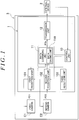
Fig.1 is a block diagram that shows an instance of a configuration of a multiplexer and the like according to the invention. -
Fig.2 (a) is a view that shows data structure for explaining a structure of first packet data, andFig.2(b) is a view that shows data structure for explaining a structure of second packet data, andFig.2 (c) is a view that shows data structure for explaining a structure of combined data. -
Fig.3 (a) is a view that shows data structure for explaining the first packet data and the like, andFig.3(b) is a view that shows data structure for explaining the second packet data and the like. -
Fig.4(a), (b) are views that show data structure for explaining effects of the invention. -
Fig.5 is a block diagram that shows an instance of a conventional configuration of the multiplexer. - Embodiments of the invention are mentioned, referring to appended drawings
Figs.1 to 4 . - A multiplexer according to the invention is exemplarily shown with a
reference number 1 inFig.1 , and has - ▪ a
first reception unit 101 that sequentially receives image signals from a first camera C1 ("the first packet data" hereinafter) PD1, - ▪ a
second reception unit 102 that sequentially receives image signals from a second camera C2 ("the second packet data" hereinafter) PD2, - ▪ a
data combining unit 11 that connects with thereception units reception units - ▪ a
transmission unit 12 that connects with thedata combining unit 11 and transmits the combined data PDS to an external device 2. As exemplarily shown inFig.2(c) , the combined data PDS prepared by thedata combining unit 11 is made by alternately arranging the first packet data PD1 and the second packet data PD2, one of the first packet data PD1 (that is, the first packet data PD1 successively arranged in the combined data PDS) is data smaller than data for one screen, and one of the second packet data PD2 (that is, the second packet data PD2 successively arranged in the combined data PDS) is data smaller than data for one screen. Concretely, one of the first packet data PD1 and one of the second packet data PD2 may be image data of one pixel. That is, when the image data (that is, the image data per pixel) sequentially transmitted from the first camera C1 to thefirst reception unit 101 is PD11, PD12, PD13, ... as exemplarily shown inFig.2 (a) , and the image data (that is, the image data per pixel) sequentially transmitted from the second camera C2 to thesecond reception unit 102 is PD21, PD22, PD23, ... as exemplarily shown inFig.2(b) , the combined data PDS may be comprised of PD11, PD21, PD12, PD22, PD13, PD23, as exemplarily shown inFig.2(c) . Besides, one of the first packet data PD1 and one of the second packet data PD2 may be the image data comprised of plural pixels. Furthermore, one of the first packet data PD1 and one of the second packet data PD2 may be the image data of one line. In addition, one of the first packet data PD1 and one of the second packet data PD2 may be the image data of plural lines. - Two or
more reception units reference numbers data combining unit 11, the combined data PDS may be arranged in order of the first packet data, the second packet data, ... and the n-th packet data, and any of the packet data (that is, each packet data sequentially arranged in the combined data) may be data smaller than data for one screen. - The camera C1, ... may start to capture the images by sending trigger signals from a
control unit 13. - The
data combining unit 11 may have adata saving unit 110 that sequentially stores one of both, or both, the first packet data PD1 received by thefirst reception unit 101, and the second packet data PD2 received by thesecond reception unit 102. - When capturing images through the first camera C1 or the second camera C2, it is necessary to secure exposure time before capturing images. When capturing images through the first camera C1, and thereafter capturing images through the second camera C2, it is necessary to secure the exposure time for each camera, C1 or C2, so that it is not possible to capture images during each exposure time. But, capturing images through the first camera C1 and the second camera C2 are simultaneously done according to the invention. Then, it is possible to simultaneously take respective exposure times, and to prevent waste of time in comparison with such a case where the exposure time should be separately secured.
- If all of the data for one screen of one camera, such as the first camera C1, is transferred to the external device 2, and thereafter, the data for one screen of the other camera, such as the second camera C2, is transferred to the external device 2, a buffer of large capacity, such as a frame buffer is necessary, and the device may be made correspondingly large and expensive. But, one of the first packet data PD1 (that is, the first packet data PD1 sequentially arranged in the combined data PDS) is data smaller than data for one screen, and one of the second packet data PD2 (that is, the second packet data PD2 sequentially arranged in the combined data PDS) is data smaller than data for one screen according to the invention, so that a buffer of large capacity, such as a frame buffer is not necessary, and the device may be made correspondingly compact and inexpensive.
- On the other hand, an image capturing device 2 may have the first camera C1, the second camera C2 and the above-mentioned
multiplexer 1. Preferably, the above-mentioned first packet data PD1 (that is, the first packet data PD1 transmitted from the first camera C1 to the first reception unit 101) is comprised of two packet data PD1A, PD1B each having the same contents, as exemplarily shown inFig.3(a) , and one packet data ("the first front packet data" hereinafter) PD1A is transferred, and thereafter the other packet data ("the first rear packet data" hereinafter) PD1B is transferred, spacing a predetermined idle time I1. Preferably, the above-mentioned second packet data PD2 (that is, the second packet data PD2 transmitted from the second camera C2 to the second reception unit 102) is comprised of two packet data PD2A, PD2B each having the same contents, as exemplarily shown inFig.3(b) , and one packet data ("the second front packet data" hereinafter) PD2A is transferred, and thereafter the other packet data ("the second rear packet data" hereinafter) PD2B is transferred, spacing a predeterminedidle time 12. Preferably, the following expressions (1) through (4) are satisfied provided that duration of noise N to occur at intervals of 10µsec or more ("the low frequency noise" hereinafter) is LN, time with no noise from occurrence of one low frequency noise N to next occurrence of low frequency noise N is LC, length of the first front packet data PD1A and the first rear packet data PD1B is LP1, length of a predetermined idle time I1 from the transmission of the first front packet data PD1A to the transmission of the first rear packet data PD1B is LI1, length of the second front packet data PD2A and the second rear packet data PD2B is LP2, and length of a predetermined idle time I2 from the transmission of the second front packet data PD2A to the transmission of the second rear packet data PD2B is LI2.


- If the expression (1) is not satisfied, the first front packet data PD1A and the first rear packet data PD1B may receive influences from the same one low frequency noise N, as exemplarily shown with hatched areas in
Fig.4(a) . If the expression (2) is not satisfied, the first front packet data PD1A and the first rear packet data PD1B may respectively receive influences from respectively separate low frequency noises, as exemplarily shown with hatched areas inFig.4(b) since both packet data are too long. Regarding the second packet data PD2, similarly, if the expression (3) is not satisfied, the second front packet data PD2A and the second rear packet data PD2B may receive influences from the same one low frequency noise N. If the expression (4) is not satisfied, the second front packet data PD2A and the second rear packet data PD2B may respectively receive influences from respectively separate low frequency noises since both packet data are too long. But, it is possible to avoid such situations according to the invention. - Since the time with no noise LC of the low frequency noise N is 10µsec or so, preferably, the length LP1 of one packet data PD1A, PD1B may be shorter than "5µsec - LI1/2". If transfer rate of the packet data PD1A, PD1B is 1.25Gbps, preferably, size of one of packet data PD1A, PD1B is 64 words or more, and 112 words or less, and the length LI1 of the idle time I1 is 10 words or so. Regarding the second packet data PD2, similarly, the length LP2 of one packet data PD2A, PD2B is shorter than "5µsec - LI2/2". If transfer rate of the packet data PD2A, PD2B is 1.25Gbps, preferably, size of one of packet data PD2A, PD2B is 64 words or more, and 112 words or less, and the length LI2 of the idle time I1 is 10 words or so. In the invention, one word is 4 bites = 32 bits, but actual transfer length (the length at the time of transfer) is 40 bits by 10b/8b conversion. According to a result of an experiment for influences from the low frequency noises, if the low frequency noise ±4kV is given to a 3CFB cable of 40m in addition to the above-mentioned conditions, the length is 36 bites or so at the maximum. Such a length varies depending on the transfer rate, the length and the thickness of the cable and noise voltage.
- Preferably, the time with no noise LC is 10µsec or more, and 200µsec or less, the transfer rate for transferring the packet data PD1A, PD1B, ... is 1.25Gbps or more, and 6.25Gbps or less, the size of the packet data PD1A, PD1B, ... is 1 word or more, and 560 words or less, and the length of the idle time I1, I2 is 10 words or more, and 100 words or less.
- According to the invention, at least one packet data of two packet data having the same contents which are sequentially transmitted (that is, the first front packet data PD1A and the first rear packet data PD1B, or the second front packet data PD2A and the second rear packet data PD2B) are received by the
respective reception units - In the above-mentioned embodiment, the packet data PD1A, PD1B, ... having the same contents are transmitted twice from the respective cameras C1, C2 to the
respective reception units - It is possible to apply the invention to CoaXpress standards, and also apply to such a case where packetized data is transmitted, such as a case where data is transmitted through the Ethernet (registered trademark) cable or with a USB, in addition to the CoaXpress standards . By transmitting the packet data having the same contents twice, usable band is made smaller, but it is possible to sufficiently achieve goals of 200Mbps since the CoaXpress standards have the band from 1.25Gbps to 6.125Gbps. In the CoaXpress standards, it is possible to detect data disturbance when it occurs through CRC check (Cyclic Redundancy Check: It is possible to detect data errors, but is not possible to restore the data) since a CRC code is attached to the packetized data. So, the packet data that is correctly transmitted may be selected. When applying the invention to the cases excluding the CoaXpress standards, it is necessary to add the above-mentioned CRC code or a code for detecting errors, similar to the CRC code to the packet data. Preferably, the first camera C1 transmits the first front packet data PD1A and the first rear packet data PD1B each attaching the code for detecting errors to the
first reception unit 101, and thefirst reception unit 101 detects data disturbance of the first front packet data PD1A or the first rear packet data PD1B by checking the code for detecting errors from the first camera C1 and transmits the first front packet data PD1A or the first rear packet data PD1B where the data disturbance is not detected to thedata combining unit 11. Besides, preferably, the second camera C2 transmits the second front packet data PD2A and the second rear packet data PD2B each attaching the code for detecting errors to thesecond reception unit 102, and thesecond reception unit 102 detects data disturbance of the second front packet data PD2A or the second rear packet data PD2B by checking the code for detecting errors from the second camera C2 and transmits the second front packet data PD2A or the second rear packet data PD2B where the data disturbance is not detected to thedata combining unit 11. - This invention can be also applied to an use to form parallax images in such a manner that left eye images are captured through the first camera C1 and right eye images are captured through the second camera C2, and these image signals (packet data) are transmitted to the external device 2.
-
- 1
- Multiplexer
- 2
- External device
- 3
- Image capturing device
- 11
- Data combining unit
- 12
- Transmission unit
- 101
- First reception unit
- 102
- Second reception unit
- 110
- Data saving unit
- C1
- First camera
- C2
- Second camera
- I1, I2
- Idle time
- N
- Low frequency noise
- PD1
- First packet data
- PD1A
- First front packet data
- PD1B
- First rear packet data
- PD2
- Second packet data
- PD2A
- Second front packet data
- PD2B
- Second rear packet data
- PDS
- Combined data
the second packet data (PD2) successively arranged in the combined data (PDS) is data smaller than data for one screen.
the second packet data (PD2) to be transmitted from the second camera (C2) to the second reception unit (102) is comprised of a second front packet data (PD2A) and a second rear packet data (PD2B) having the same contents as the second front packet data (PD2A), to be transmitted spacing a predetermined idle time (12) after transmitting the second front packet data (PD2A), as exemplarily shown in
below-mentioned expressions (1) through (4) are satisfied provided that duration of noise to occur at intervals of 10µsec or more (See N in


Claims (5)
- A multiplexer, comprising:a first reception unit that sequentially receives first packet data that are image signals from a first camera;a second reception unit that sequentially receives second packet data that are image signals from a second camera;a data combining unit that connects with the reception units and prepares combined data where the first packet data and the second packet data are alternately arranged; anda transmission unit that connects with the data combining unit and transmits the combined data to an external device;wherein the first packet data successively arranged in the combined data is data smaller than data for one screen; and
the second packet data successively arranged in the combined data is data smaller than data for one screen. - The multiplexer according to claim 1, wherein the first packet data sequentially arranged in the combined data and the second packet data sequentially arranged in the combined data are respectively image data comprised of one pixel, plural pixels, one line or plural lines.
- The multiplexer according to claim 1, wherein the data combining unit has a data saving unit that sequentially stores the first packet data received by the first reception unit and/or the second packet data received by the second reception unit.
- An image capturing device, comprising:a first camera and a second camera; andthe multiplexer according to claim 1,whereby the first packet data to be transmitted from the first camera to the first reception unit is comprised of a first front packet data and a first rear packet data having the same contents as the first front packet data, to be transmitted spacing a predetermined idle time after transmitting the first front packet data;
the second packet data to be transmitted from the second camera to the second reception unit is comprised of a second front packet data and a second rear packet data having the same contents as the second front packet data, to be transmitted spacing a predetermined idle time after transmitting the second front packet data; and
below-mentioned expressions (1) through (4) are satisfied provided that duration of noise to occur at intervals of 10µsec or more ("the low frequency noise" hereinafter) is LN, time with no noise from occurrence of one low frequency noise to next occurrence of low frequency noise is LC, length of the first front packet data and the first rear packet data is LP1, length of a predetermined idle time from the transmission of the first front packet data to the transmission of the first rear packet data is LI1, length of the second front packet data and the second rear packet data is LP2, and length of a predetermined idle time from the transmission of the second front packet data to the transmission of the second rear packet data is LI2.


- The image capturing device according to claim 4,wherein the first camera transmits the first front packet data and the first rear packet data each attaching a code for detecting errors to the first reception unit,the second camera transmits the second front packet data and the second rear packet data each attaching a code for detecting errors to the second reception unit,the first reception unit detects data disturbance of the first front packet data or the first rear packet data by checking the code for detecting errors from the first camera and transmits the first front packet data or the first rear packet data where the data disturbance is not detected to the data combining unit, andthe second reception unit detects data disturbance of the second front packet data or the second rear packet data by checking the code for detecting errors from the second camera and transmits the second front packet data or the second rear packet data where the data disturbance is not detected to the data combining unit.
Applications Claiming Priority (2)
| Application Number | Priority Date | Filing Date | Title |
|---|---|---|---|
| JP2016086017 | 2016-04-22 | ||
| PCT/JP2017/015967 WO2017183706A1 (en) | 2016-04-22 | 2017-04-21 | Multiplexer and image capturing device provided with said multiplexer |
Publications (3)
| Publication Number | Publication Date |
|---|---|
| EP3448015A1 true EP3448015A1 (en) | 2019-02-27 |
| EP3448015A4 EP3448015A4 (en) | 2019-11-27 |
| EP3448015B1 EP3448015B1 (en) | 2021-11-24 |
Family
ID=60116876
Family Applications (1)
| Application Number | Title | Priority Date | Filing Date |
|---|---|---|---|
| EP17786043.4A Active EP3448015B1 (en) | 2016-04-22 | 2017-04-21 | Image capturing device provided with multiplexer |
Country Status (6)
| Country | Link |
|---|---|
| US (1) | US10469799B2 (en) |
| EP (1) | EP3448015B1 (en) |
| JP (1) | JP6993323B2 (en) |
| CN (1) | CN109076162B (en) |
| TW (1) | TWI726091B (en) |
| WO (1) | WO2017183706A1 (en) |
Families Citing this family (2)
| Publication number | Priority date | Publication date | Assignee | Title |
|---|---|---|---|---|
| WO2022091741A1 (en) | 2020-10-29 | 2022-05-05 | 興和株式会社 | Multiplexer and imaging system |
| WO2024117148A1 (en) | 2022-11-30 | 2024-06-06 | 興和株式会社 | Multiplexer |
Family Cites Families (22)
| Publication number | Priority date | Publication date | Assignee | Title |
|---|---|---|---|---|
| US4667321A (en) * | 1983-11-14 | 1987-05-19 | Tandem Computers Incorporated | Input-output multiplexer-demultiplexer communications channel |
| US5883676A (en) * | 1994-11-28 | 1999-03-16 | Sanyo Electric Company, Ltd. | Image signal outputting apparatus |
| TW432870B (en) | 1995-07-11 | 2001-05-01 | Ultrak Inc | Video multiplexer |
| JP3363673B2 (en) * | 1995-10-03 | 2003-01-08 | 三洋電機株式会社 | Video signal processing device |
| US5828293A (en) * | 1997-06-10 | 1998-10-27 | Northern Telecom Limited | Data transmission over a power line communications system |
| JP3438564B2 (en) * | 1998-01-26 | 2003-08-18 | ソニー株式会社 | Digital signal multiplexing apparatus and method, recording medium |
| US6333759B1 (en) * | 1999-03-16 | 2001-12-25 | Joseph J. Mazzilli | 360 ° automobile video camera system |
| JP2000341231A (en) * | 1999-05-25 | 2000-12-08 | Canon Inc | Multiplexing apparatus, method and computer-readable storage medium |
| TW441208B (en) * | 1999-09-27 | 2001-06-16 | Rf Link Systems Inc | Device and method for asynchronous time-division multiplexing access electric signal transmission |
| GB2372742A (en) * | 2001-03-03 | 2002-09-04 | Univ Leiden | C2,5'-Disubstituted and N6,C2,5'-trisubstituted adenosine derivatives and their different uses |
| US20040075741A1 (en) * | 2002-10-17 | 2004-04-22 | Berkey Thomas F. | Multiple camera image multiplexer |
| JP2006121394A (en) * | 2004-10-21 | 2006-05-11 | Matsushita Electric Ind Co Ltd | Wireless communication apparatus and wireless communication system |
| JP4832828B2 (en) * | 2005-07-29 | 2011-12-07 | 株式会社オートネットワーク技術研究所 | Communications system |
| JP2007228258A (en) * | 2006-02-23 | 2007-09-06 | Mitsubishi Electric Corp | Video transmission system |
| JP4940030B2 (en) * | 2007-06-26 | 2012-05-30 | 富士通株式会社 | Transmission device, reception device, and program |
| JP2010109529A (en) * | 2008-10-29 | 2010-05-13 | Renesas Technology Corp | Multiplexing controller |
| JP4653844B2 (en) | 2009-07-08 | 2011-03-16 | ファナック株式会社 | Image processing apparatus for robot system and robot system including the same |
| DE102010003226A1 (en) * | 2010-03-24 | 2011-09-29 | Cube Optics Ag | Multiplexer / demultiplexer with adjustment mirror |
| US9413985B2 (en) * | 2012-09-12 | 2016-08-09 | Lattice Semiconductor Corporation | Combining video and audio streams utilizing pixel repetition bandwidth |
| JP6041697B2 (en) * | 2013-02-15 | 2016-12-14 | 三菱重工業株式会社 | Control device and industrial machine |
| CN103347144B (en) * | 2013-07-01 | 2016-08-24 | 广东威创视讯科技股份有限公司 | A kind of video synchronization method based on camera shooting |
| US9967446B2 (en) * | 2015-09-09 | 2018-05-08 | Itx-M2M Co., Ltd. | Personalized shopping mall system using virtual camera |
-
2017
- 2017-04-21 CN CN201780023026.XA patent/CN109076162B/en active Active
- 2017-04-21 EP EP17786043.4A patent/EP3448015B1/en active Active
- 2017-04-21 TW TW106113358A patent/TWI726091B/en active
- 2017-04-21 JP JP2018513220A patent/JP6993323B2/en active Active
- 2017-04-21 WO PCT/JP2017/015967 patent/WO2017183706A1/en not_active Ceased
- 2017-04-21 US US16/092,015 patent/US10469799B2/en active Active
Also Published As
| Publication number | Publication date |
|---|---|
| EP3448015A4 (en) | 2019-11-27 |
| US20190124293A1 (en) | 2019-04-25 |
| US10469799B2 (en) | 2019-11-05 |
| TWI726091B (en) | 2021-05-01 |
| CN109076162A (en) | 2018-12-21 |
| WO2017183706A1 (en) | 2017-10-26 |
| EP3448015B1 (en) | 2021-11-24 |
| TW201739240A (en) | 2017-11-01 |
| JPWO2017183706A1 (en) | 2019-02-28 |
| CN109076162B (en) | 2020-09-22 |
| JP6993323B2 (en) | 2022-01-13 |
Similar Documents
| Publication | Publication Date | Title |
|---|---|---|
| EP4636648A1 (en) | Image sensor architecture | |
| US9792081B2 (en) | Display device with plural displays | |
| US10148455B2 (en) | Data processing apparatus, method for controlling data processing apparatus, and program | |
| US11452487B2 (en) | X-ray detector module, medical imaging device and method for operating an x-ray detector module | |
| EP2814237A1 (en) | Image transferring method and image transferring apparatus | |
| CN108694995B (en) | Medical diagnosis system and method | |
| EP3448015B1 (en) | Image capturing device provided with multiplexer | |
| EP3214787B1 (en) | Packet data transmission device and packet data transmission method | |
| CN116017185B (en) | Multichannel CMOS image synchronous transmission integration method and system thereof | |
| CN103384305A (en) | Detection apparatus, power supply apparatus, power reception apparatus, power supply system, and program | |
| KR101230397B1 (en) | High speed data transmission / reception method and apparatus | |
| CN115776325B (en) | An event scheduling method, device and storage medium applied to a satellite system | |
| HK1263209B (en) | Image capturing device provided with multiplexer | |
| HK1263209A1 (en) | Image capturing device provided with multiplexer | |
| JP2012182712A (en) | Imaging device | |
| US10786221B2 (en) | Radiation imaging apparatus, radiation imaging system, and method for controlling radiation imaging system | |
| KR101461850B1 (en) | Method and apparatus for exchanging protocol | |
| JP6643449B2 (en) | Radiation imaging apparatus, radiation imaging system, control method of radiation imaging apparatus, and program | |
| JP7571034B2 (en) | COMMUNICATION DEVICE, COMMUNICATION METHOD, AND PROGRAM | |
| KR101269263B1 (en) | data transmission processing device and transmission method thereof | |
| EP3101888B1 (en) | Image-capturing device, camera system, and signal output method | |
| KR20100133807A (en) | Resolution Conversion Method for Preview Mode and Image Sensor Using the Same | |
| KR20120085695A (en) | Method and Apparatus for Transmitting/Receiving Image Data with High Speed | |
| JP2015150001A (en) | Information processing apparatus, information processing method, and program | |
| CN102469277A (en) | Image outputting apparatus, image outputting method, image processing apparatus, image processing method, program, data structure and imaging apparatus |
Legal Events
| Date | Code | Title | Description |
|---|---|---|---|
| STAA | Information on the status of an ep patent application or granted ep patent |
Free format text: STATUS: THE INTERNATIONAL PUBLICATION HAS BEEN MADE |
|
| PUAI | Public reference made under article 153(3) epc to a published international application that has entered the european phase |
Free format text: ORIGINAL CODE: 0009012 |
|
| STAA | Information on the status of an ep patent application or granted ep patent |
Free format text: STATUS: REQUEST FOR EXAMINATION WAS MADE |
|
| 17P | Request for examination filed |
Effective date: 20181102 |
|
| AK | Designated contracting states |
Kind code of ref document: A1 Designated state(s): AL AT BE BG CH CY CZ DE DK EE ES FI FR GB GR HR HU IE IS IT LI LT LU LV MC MK MT NL NO PL PT RO RS SE SI SK SM TR |
|
| AX | Request for extension of the european patent |
Extension state: BA ME |
|
| DAV | Request for validation of the european patent (deleted) | ||
| DAX | Request for extension of the european patent (deleted) | ||
| A4 | Supplementary search report drawn up and despatched |
Effective date: 20191025 |
|
| RIC1 | Information provided on ipc code assigned before grant |
Ipc: G06F 11/08 20060101ALI20191021BHEP Ipc: H04N 7/08 20060101AFI20191021BHEP Ipc: H04N 21/2365 20110101ALI20191021BHEP |
|
| STAA | Information on the status of an ep patent application or granted ep patent |
Free format text: STATUS: EXAMINATION IS IN PROGRESS |
|
| 17Q | First examination report despatched |
Effective date: 20200922 |
|
| GRAP | Despatch of communication of intention to grant a patent |
Free format text: ORIGINAL CODE: EPIDOSNIGR1 |
|
| STAA | Information on the status of an ep patent application or granted ep patent |
Free format text: STATUS: GRANT OF PATENT IS INTENDED |
|
| RIC1 | Information provided on ipc code assigned before grant |
Ipc: H04N 5/232 20060101AFI20210715BHEP Ipc: H04N 7/08 20060101ALI20210715BHEP Ipc: H04N 21/2365 20110101ALI20210715BHEP Ipc: G06F 11/08 20060101ALI20210715BHEP |
|
| INTG | Intention to grant announced |
Effective date: 20210811 |
|
| GRAS | Grant fee paid |
Free format text: ORIGINAL CODE: EPIDOSNIGR3 |
|
| GRAA | (expected) grant |
Free format text: ORIGINAL CODE: 0009210 |
|
| STAA | Information on the status of an ep patent application or granted ep patent |
Free format text: STATUS: THE PATENT HAS BEEN GRANTED |
|
| AK | Designated contracting states |
Kind code of ref document: B1 Designated state(s): AL AT BE BG CH CY CZ DE DK EE ES FI FR GB GR HR HU IE IS IT LI LT LU LV MC MK MT NL NO PL PT RO RS SE SI SK SM TR |
|
| REG | Reference to a national code |
Ref country code: GB Ref legal event code: FG4D |
|
| REG | Reference to a national code |
Ref country code: AT Ref legal event code: REF Ref document number: 1450771 Country of ref document: AT Kind code of ref document: T Effective date: 20211215 |
|
| REG | Reference to a national code |
Ref country code: DE Ref legal event code: R096 Ref document number: 602017049855 Country of ref document: DE |
|
| REG | Reference to a national code |
Ref country code: IE Ref legal event code: FG4D |
|
| REG | Reference to a national code |
Ref country code: LT Ref legal event code: MG9D |
|
| REG | Reference to a national code |
Ref country code: NL Ref legal event code: MP Effective date: 20211124 |
|
| REG | Reference to a national code |
Ref country code: AT Ref legal event code: MK05 Ref document number: 1450771 Country of ref document: AT Kind code of ref document: T Effective date: 20211124 |
|
| PG25 | Lapsed in a contracting state [announced via postgrant information from national office to epo] |
Ref country code: RS Free format text: LAPSE BECAUSE OF FAILURE TO SUBMIT A TRANSLATION OF THE DESCRIPTION OR TO PAY THE FEE WITHIN THE PRESCRIBED TIME-LIMIT Effective date: 20211124 Ref country code: LT Free format text: LAPSE BECAUSE OF FAILURE TO SUBMIT A TRANSLATION OF THE DESCRIPTION OR TO PAY THE FEE WITHIN THE PRESCRIBED TIME-LIMIT Effective date: 20211124 Ref country code: FI Free format text: LAPSE BECAUSE OF FAILURE TO SUBMIT A TRANSLATION OF THE DESCRIPTION OR TO PAY THE FEE WITHIN THE PRESCRIBED TIME-LIMIT Effective date: 20211124 Ref country code: BG Free format text: LAPSE BECAUSE OF FAILURE TO SUBMIT A TRANSLATION OF THE DESCRIPTION OR TO PAY THE FEE WITHIN THE PRESCRIBED TIME-LIMIT Effective date: 20220224 Ref country code: AT Free format text: LAPSE BECAUSE OF FAILURE TO SUBMIT A TRANSLATION OF THE DESCRIPTION OR TO PAY THE FEE WITHIN THE PRESCRIBED TIME-LIMIT Effective date: 20211124 |
|
| PG25 | Lapsed in a contracting state [announced via postgrant information from national office to epo] |
Ref country code: IS Free format text: LAPSE BECAUSE OF FAILURE TO SUBMIT A TRANSLATION OF THE DESCRIPTION OR TO PAY THE FEE WITHIN THE PRESCRIBED TIME-LIMIT Effective date: 20220324 Ref country code: SE Free format text: LAPSE BECAUSE OF FAILURE TO SUBMIT A TRANSLATION OF THE DESCRIPTION OR TO PAY THE FEE WITHIN THE PRESCRIBED TIME-LIMIT Effective date: 20211124 Ref country code: PT Free format text: LAPSE BECAUSE OF FAILURE TO SUBMIT A TRANSLATION OF THE DESCRIPTION OR TO PAY THE FEE WITHIN THE PRESCRIBED TIME-LIMIT Effective date: 20220324 Ref country code: PL Free format text: LAPSE BECAUSE OF FAILURE TO SUBMIT A TRANSLATION OF THE DESCRIPTION OR TO PAY THE FEE WITHIN THE PRESCRIBED TIME-LIMIT Effective date: 20211124 Ref country code: NO Free format text: LAPSE BECAUSE OF FAILURE TO SUBMIT A TRANSLATION OF THE DESCRIPTION OR TO PAY THE FEE WITHIN THE PRESCRIBED TIME-LIMIT Effective date: 20220224 Ref country code: NL Free format text: LAPSE BECAUSE OF FAILURE TO SUBMIT A TRANSLATION OF THE DESCRIPTION OR TO PAY THE FEE WITHIN THE PRESCRIBED TIME-LIMIT Effective date: 20211124 Ref country code: LV Free format text: LAPSE BECAUSE OF FAILURE TO SUBMIT A TRANSLATION OF THE DESCRIPTION OR TO PAY THE FEE WITHIN THE PRESCRIBED TIME-LIMIT Effective date: 20211124 Ref country code: HR Free format text: LAPSE BECAUSE OF FAILURE TO SUBMIT A TRANSLATION OF THE DESCRIPTION OR TO PAY THE FEE WITHIN THE PRESCRIBED TIME-LIMIT Effective date: 20211124 Ref country code: GR Free format text: LAPSE BECAUSE OF FAILURE TO SUBMIT A TRANSLATION OF THE DESCRIPTION OR TO PAY THE FEE WITHIN THE PRESCRIBED TIME-LIMIT Effective date: 20220225 Ref country code: ES Free format text: LAPSE BECAUSE OF FAILURE TO SUBMIT A TRANSLATION OF THE DESCRIPTION OR TO PAY THE FEE WITHIN THE PRESCRIBED TIME-LIMIT Effective date: 20211124 |
|
| PG25 | Lapsed in a contracting state [announced via postgrant information from national office to epo] |
Ref country code: SM Free format text: LAPSE BECAUSE OF FAILURE TO SUBMIT A TRANSLATION OF THE DESCRIPTION OR TO PAY THE FEE WITHIN THE PRESCRIBED TIME-LIMIT Effective date: 20211124 Ref country code: SK Free format text: LAPSE BECAUSE OF FAILURE TO SUBMIT A TRANSLATION OF THE DESCRIPTION OR TO PAY THE FEE WITHIN THE PRESCRIBED TIME-LIMIT Effective date: 20211124 Ref country code: RO Free format text: LAPSE BECAUSE OF FAILURE TO SUBMIT A TRANSLATION OF THE DESCRIPTION OR TO PAY THE FEE WITHIN THE PRESCRIBED TIME-LIMIT Effective date: 20211124 Ref country code: EE Free format text: LAPSE BECAUSE OF FAILURE TO SUBMIT A TRANSLATION OF THE DESCRIPTION OR TO PAY THE FEE WITHIN THE PRESCRIBED TIME-LIMIT Effective date: 20211124 Ref country code: DK Free format text: LAPSE BECAUSE OF FAILURE TO SUBMIT A TRANSLATION OF THE DESCRIPTION OR TO PAY THE FEE WITHIN THE PRESCRIBED TIME-LIMIT Effective date: 20211124 Ref country code: CZ Free format text: LAPSE BECAUSE OF FAILURE TO SUBMIT A TRANSLATION OF THE DESCRIPTION OR TO PAY THE FEE WITHIN THE PRESCRIBED TIME-LIMIT Effective date: 20211124 |
|
| REG | Reference to a national code |
Ref country code: DE Ref legal event code: R097 Ref document number: 602017049855 Country of ref document: DE |
|
| PLBE | No opposition filed within time limit |
Free format text: ORIGINAL CODE: 0009261 |
|
| STAA | Information on the status of an ep patent application or granted ep patent |
Free format text: STATUS: NO OPPOSITION FILED WITHIN TIME LIMIT |
|
| PG25 | Lapsed in a contracting state [announced via postgrant information from national office to epo] |
Ref country code: AL Free format text: LAPSE BECAUSE OF FAILURE TO SUBMIT A TRANSLATION OF THE DESCRIPTION OR TO PAY THE FEE WITHIN THE PRESCRIBED TIME-LIMIT Effective date: 20211124 |
|
| 26N | No opposition filed |
Effective date: 20220825 |
|
| REG | Reference to a national code |
Ref country code: DE Ref legal event code: R079 Ref document number: 602017049855 Country of ref document: DE Free format text: PREVIOUS MAIN CLASS: H04N0005232000 Ipc: H04N0023600000 |
|
| PG25 | Lapsed in a contracting state [announced via postgrant information from national office to epo] |
Ref country code: SI Free format text: LAPSE BECAUSE OF FAILURE TO SUBMIT A TRANSLATION OF THE DESCRIPTION OR TO PAY THE FEE WITHIN THE PRESCRIBED TIME-LIMIT Effective date: 20211124 |
|
| REG | Reference to a national code |
Ref country code: CH Ref legal event code: PL |
|
| REG | Reference to a national code |
Ref country code: BE Ref legal event code: MM Effective date: 20220430 |
|
| PG25 | Lapsed in a contracting state [announced via postgrant information from national office to epo] |
Ref country code: MC Free format text: LAPSE BECAUSE OF FAILURE TO SUBMIT A TRANSLATION OF THE DESCRIPTION OR TO PAY THE FEE WITHIN THE PRESCRIBED TIME-LIMIT Effective date: 20211124 Ref country code: LU Free format text: LAPSE BECAUSE OF NON-PAYMENT OF DUE FEES Effective date: 20220421 Ref country code: LI Free format text: LAPSE BECAUSE OF NON-PAYMENT OF DUE FEES Effective date: 20220430 Ref country code: CH Free format text: LAPSE BECAUSE OF NON-PAYMENT OF DUE FEES Effective date: 20220430 |
|
| PG25 | Lapsed in a contracting state [announced via postgrant information from national office to epo] |
Ref country code: BE Free format text: LAPSE BECAUSE OF NON-PAYMENT OF DUE FEES Effective date: 20220430 |
|
| PG25 | Lapsed in a contracting state [announced via postgrant information from national office to epo] |
Ref country code: IE Free format text: LAPSE BECAUSE OF NON-PAYMENT OF DUE FEES Effective date: 20220421 |
|
| PG25 | Lapsed in a contracting state [announced via postgrant information from national office to epo] |
Ref country code: IT Free format text: LAPSE BECAUSE OF FAILURE TO SUBMIT A TRANSLATION OF THE DESCRIPTION OR TO PAY THE FEE WITHIN THE PRESCRIBED TIME-LIMIT Effective date: 20211124 |
|
| REG | Reference to a national code |
Ref country code: DE Ref legal event code: R082 Ref document number: 602017049855 Country of ref document: DE Representative=s name: SEYER & NOBBE PATENTANWAELTE PARTNERSCHAFTSGES, DE |
|
| PG25 | Lapsed in a contracting state [announced via postgrant information from national office to epo] |
Ref country code: HU Free format text: LAPSE BECAUSE OF FAILURE TO SUBMIT A TRANSLATION OF THE DESCRIPTION OR TO PAY THE FEE WITHIN THE PRESCRIBED TIME-LIMIT; INVALID AB INITIO Effective date: 20170421 |
|
| PG25 | Lapsed in a contracting state [announced via postgrant information from national office to epo] |
Ref country code: MK Free format text: LAPSE BECAUSE OF FAILURE TO SUBMIT A TRANSLATION OF THE DESCRIPTION OR TO PAY THE FEE WITHIN THE PRESCRIBED TIME-LIMIT Effective date: 20211124 Ref country code: CY Free format text: LAPSE BECAUSE OF FAILURE TO SUBMIT A TRANSLATION OF THE DESCRIPTION OR TO PAY THE FEE WITHIN THE PRESCRIBED TIME-LIMIT Effective date: 20211124 |
|
| PG25 | Lapsed in a contracting state [announced via postgrant information from national office to epo] |
Ref country code: TR Free format text: LAPSE BECAUSE OF FAILURE TO SUBMIT A TRANSLATION OF THE DESCRIPTION OR TO PAY THE FEE WITHIN THE PRESCRIBED TIME-LIMIT Effective date: 20211124 |
|
| PG25 | Lapsed in a contracting state [announced via postgrant information from national office to epo] |
Ref country code: MT Free format text: LAPSE BECAUSE OF FAILURE TO SUBMIT A TRANSLATION OF THE DESCRIPTION OR TO PAY THE FEE WITHIN THE PRESCRIBED TIME-LIMIT Effective date: 20211124 |
|
| PGFP | Annual fee paid to national office [announced via postgrant information from national office to epo] |
Ref country code: DE Payment date: 20250305 Year of fee payment: 9 |
|
| PGFP | Annual fee paid to national office [announced via postgrant information from national office to epo] |
Ref country code: GB Payment date: 20260316 Year of fee payment: 10 |
|
| PGFP | Annual fee paid to national office [announced via postgrant information from national office to epo] |
Ref country code: FR Payment date: 20260309 Year of fee payment: 10 |