EP3447796A1 - Igbt module assembly - Google Patents
Igbt module assembly Download PDFInfo
- Publication number
- EP3447796A1 EP3447796A1 EP17785325.6A EP17785325A EP3447796A1 EP 3447796 A1 EP3447796 A1 EP 3447796A1 EP 17785325 A EP17785325 A EP 17785325A EP 3447796 A1 EP3447796 A1 EP 3447796A1
- Authority
- EP
- European Patent Office
- Prior art keywords
- igbt module
- cooling plate
- side face
- igbt
- module assembly
- Prior art date
- Legal status (The legal status is an assumption and is not a legal conclusion. Google has not performed a legal analysis and makes no representation as to the accuracy of the status listed.)
- Granted
Links
Images



Classifications
-
- H—ELECTRICITY
- H10—SEMICONDUCTOR DEVICES; ELECTRIC SOLID-STATE DEVICES NOT OTHERWISE PROVIDED FOR
- H10W—GENERIC PACKAGES, INTERCONNECTIONS, CONNECTORS OR OTHER CONSTRUCTIONAL DETAILS OF DEVICES COVERED BY CLASS H10
- H10W40/00—Arrangements for thermal protection or thermal control
- H10W40/40—Arrangements for thermal protection or thermal control involving heat exchange by flowing fluids
- H10W40/47—Arrangements for thermal protection or thermal control involving heat exchange by flowing fluids by flowing liquids, e.g. forced water cooling
-
- H—ELECTRICITY
- H10—SEMICONDUCTOR DEVICES; ELECTRIC SOLID-STATE DEVICES NOT OTHERWISE PROVIDED FOR
- H10W—GENERIC PACKAGES, INTERCONNECTIONS, CONNECTORS OR OTHER CONSTRUCTIONAL DETAILS OF DEVICES COVERED BY CLASS H10
- H10W40/00—Arrangements for thermal protection or thermal control
- H10W40/20—Arrangements for cooling
- H10W40/22—Arrangements for cooling characterised by their shape, e.g. having conical or cylindrical projections
-
- H—ELECTRICITY
- H10—SEMICONDUCTOR DEVICES; ELECTRIC SOLID-STATE DEVICES NOT OTHERWISE PROVIDED FOR
- H10W—GENERIC PACKAGES, INTERCONNECTIONS, CONNECTORS OR OTHER CONSTRUCTIONAL DETAILS OF DEVICES COVERED BY CLASS H10
- H10W40/00—Arrangements for thermal protection or thermal control
- H10W40/20—Arrangements for cooling
- H10W40/22—Arrangements for cooling characterised by their shape, e.g. having conical or cylindrical projections
- H10W40/226—Arrangements for cooling characterised by their shape, e.g. having conical or cylindrical projections characterised by projecting parts, e.g. fins to increase surface area
-
- H—ELECTRICITY
- H10—SEMICONDUCTOR DEVICES; ELECTRIC SOLID-STATE DEVICES NOT OTHERWISE PROVIDED FOR
- H10W—GENERIC PACKAGES, INTERCONNECTIONS, CONNECTORS OR OTHER CONSTRUCTIONAL DETAILS OF DEVICES COVERED BY CLASS H10
- H10W90/00—Package configurations
-
- H—ELECTRICITY
- H10—SEMICONDUCTOR DEVICES; ELECTRIC SOLID-STATE DEVICES NOT OTHERWISE PROVIDED FOR
- H10W—GENERIC PACKAGES, INTERCONNECTIONS, CONNECTORS OR OTHER CONSTRUCTIONAL DETAILS OF DEVICES COVERED BY CLASS H10
- H10W72/00—Interconnections or connectors in packages
- H10W72/50—Bond wires
Definitions
- the disclosure relates to an electronic element, in particular to an Insulated Gate Bipolar Transistor (IGBT) module assembly.
- IGBT Insulated Gate Bipolar Transistor
- An IGBT module is a modularized semiconductor comprising an IGBT and an Fly-Wheel Diode (FWD) which are bridged and encapsulated through a particular circuit, and the heat dissipation efficiency of the IGBT module is a key factor that restricts the performance and the reliability.
- FWD Fly-Wheel Diode
- a cooling problem of the IGBT module is solved through two heat-dissipating methods, namely an air cooling method and a liquid cooling method, wherein the air cooling method is that a fan is used for blowing or pumping so as to cool the IGBT module, and has the advantages of simple structure, low cost, good safety and reliability and the disadvantages of big noise and low dissipation efficiency, and is difficult to apply to a high-power condition with a serious heat dissipation problem.
- the liquid cooling method is that refrigerant liquid with relatively high unit heat capacity is used as circulating cooling medium of a cooling plate, then an IGBT module 10 is mounted on the cooling plate 20 and transfers heat to a cooling plate 20; refrigerant pipes 30 are arranged in the cooling plate 20, and refrigerant liquid in the refrigerant pipes 30 is used for heat exchanging, so that the IGBT module can be cooled.
- the method has the advantages of high efficiency and low noise and is very suitable for a high-power condition with a serious heat dissipation problem of the IGBT module.
- the disclosure aims to provide an IGBT module assembly so as to solve the problem of a liquid cooling method in the related art that interelectrode short circuit of wiring terminals of an IGBT module is caused by condensed water, thus resulting an electrical safety accident.
- An IGBT module assembly which includes a cooling plate and an IGBT module fixedly connected on the cooling plate, a wiring terminal being arranged an end face, which is away from the cooling plate, of the IGBT module, the IGBT module including a side face adjacent to the end face, and a water guiding groove formed on the side face and the cooling plate.
- one end of the side face which is close to the cooling plate, is inclined to a center of the IGBT module.
- one end of the side face which is close to the cooling plate, is inclined at an angle of 30 degrees to 60 degrees to the center of the IGBT module.
- one end of the side face which is close to the cooling plate, is inclined at an angle 45 degrees to the center of the IGBT module.
- a semicircular open groove is formed in one end of the side face, which is close to the cooling plate, and a water guiding groove is formed by the open groove and the surface of the cooling plate.
- the IGBT module adopts a polyhedral frustum structure or a cone frustum structure.
- the IGBT module adopts a tetrahedral frustum structure, and the side face is in the shape of an isosceles trapezoid.
- a plurality of refrigerant pipes are arranged in the cooling plate in a coiled manner, and refrigerant medium flows in the refrigerant pipes.
- the cooling plate is a metal plate, and connecting holes allowing the refrigerant pipes to be arranged in a coiled manner are formed in the cooling plate in a run-through manner.
- a plurality of mounting holes are formed in the IGBT module, and threaded holes are formed in the cooling plate at the positions corresponding to the mounting holes and arranged in a manner of keeping away from the connecting holes.
- the disclosure has the following benefits: through the water guiding groove formed by the side face and the cooling plate, particularly through the water guiding groove formed in a manner that one end of the side face of the IGBT, which is close to the cooling plate, is inclined to the center of the IGBT module, so as a great amount of condensed water collected on the cooling plate can be guided and diverted out instead of flowing to the end faces of the IGBT module, on which the wiring terminals are arranged, so that the situation of interelectrode short circuit of the wiring terminals on the IGBT module can be avoided, and electrical safety accidents can be prevented.
- the IGBT module can work safely and efficiently in a high-power condition with a heat dissipation problem, so that the application filed of the IGBT module is expanded.
- cooling plate 1, cooling plate; 2, IGBT module; 3, wiring terminal; 4, water guiding groove; 5, open groove; 11, refrigerant pipe; 21, end face; 22, side face; 23, mounting hole; 10, IGBT module; 20, cooling plate; 30, refrigerant pipe.
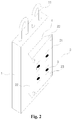
- the disclosure provides an IGBT module assembly as shown in Fig. 2 and Fig. 3 .
- the IGBT module assembly includes a cooling plate 1 and an IGBT module 2 fixedly connected to the cooling plate 1, wherein the cooling plate 1 adopts a cuboid structure, a plurality of refrigerant pipes 11 are arranged in the cooling plate in a coiled manner, and refrigerant medium flows in the refrigerant pipes 11 and used for cooling the IGBT module 2.
- connecting holes (not shown in the figure) which run through the cooling plate 1 are formed inside the cooling plate 1 and used for allowing the refrigerant pipes 11 to be arranged in a coiled manner.
- a plurality of threaded holes are formed in a surface of the cooling plate 1, which is in contact with the IGBT module 2, and keep away from the connecting holes.
- the cooling plate 1 is made of metal so as to have better thermal conductivity, and heat radiated by the IGBT module 2 is able to be transferred to the cooling plate 1, which is able to be cooled by the refrigerant medium in the refrigerant pipes 11, so that the cooling effect can be further improved.
- the IGBT module 2 includes end faces 21, which are away from the cooling plate 1, and a side face 22 adjacent to the end faces 21, wherein a plurality of wiring terminals 3 are arranged on the end faces 21 and may form electrical connection with the outside through screws.
- the side face 22 and the cooling plate 1 form a water guiding groove 4 together.
- one end of the side face 22, which is close to the cooling plate 1, is inclined to the center of the IGBT module 2, and the side face 22 arranged in an inclined manner and the cooling plate form the water guiding groove 4 together, so that the condensed water can be guided to flow out.
- one end of the side face 22, which is close to the cooling plate 1 is inclined to the center of the IGBT module 2 at an angle of 30 degrees to 60 degrees, due to the arrangement of the angle, the water guiding groove 4 has a better water guiding effect, and the comprehensive benefits are higher in terms of manufacturing techniques and material conservation. More preferably, the angle of inclination is set to be 45 degrees.
- the IGBT module 2 may adopt a polyhedral frustum structure or a cone frustum structure, as long as one end of the side face 22, which is close to the cooling plate 1, is inclined to the center of the IGBT module 2.
- the IGBT module 2 adopts a tetrahedral frustum structure, correspondingly, the side face 22 is of a trapezoidal structure, and one side of the side face 22, which is contact with the cooling plate 1, is the upper bottom edge, namely, the shorter side. Therefore, the structure of the water guiding groove can be formed.
- the side face 22 may be of an isosceles-trapezoid-like structure.
- a plurality of mounting holes 23 in one-one correspondence with threaded holes of the cooling plate 1 are formed in the IGBT module 2.
- the IGBT module 2 can be fixed on the cooling plate 1 through bolts that passing through the mounting holes 23 and in threaded connection with the threaded holes.
- the threaded holes of the cooling plate 1 are arranged in a manner of keeping away from the connecting holes, so that the problem that when the cooling plate 1 and the IGBT module 2 are assembled, refrigerant pipes 11 in the cooling plate 1 interferes with the assembling may be avoided, and the refrigerant pipes 11 are prevented from compressional deformation or damage.
- the condensed water may not flow to the surface of the IGBT module 2, on which the wiring terminals 3 are arranged.
- the condensed water is collected between the cooling plate 1 and the side face 22 of the top of the IGBT module 2, and the side face 22 is inclined to play a role of stopping, so that the condensed water may be guided to both sides of the cooling plate 1 and the IGBT module 2 and flows down along the water guiding groove 4 formed by the cooling plate 1 and the two sides of the IGBT module 2.
- the water flow may not form on the end face 21 of the IGBT module 2, on which the wiring terminals 3 are arranged, thus interelectrode short circuit of the wiring terminals 3 can be avoided.
- the IGBT module assembly is placed horizontally (the cooling plate 1 is on the upper side and the IGBT module 2 is on the lower side), as the side face 22 of the IGBT module 2 is in the form of a umbrella-shaped structure, the condensed water may flow down from the four sides 22 of the IGBT module 2, so that the wiring terminals 3 are protected from contacting the condensed water.
- the condensed water is collected at an area close to where the surface of the cooling plate 1 is in contact with the IGBT module 2, and under the influence of gravity, the condensed water may not flow to the end faces 21 of the IGBT module 2, and the wiring terminals 3 may not be in contact with the condensed water.
- the IGBT module can work safely and efficiently under a high-power condition with a dissipation problem, so that the application field of the IGBT module is expanded.
- the structure of the water guiding groove 4 is further improved based on the embodiment 1, particularly, as shown in Fig. 4 , in the embodiment, a semicircular open groove 5 is formed in one end, close to the cooling plate 1, of the side face 22 of the IGBT module 2.
- the open groove 5 and the cooling plate 1 form the water guiding groove 4 together, and the condensed water may directly flow out of the IGBT module 2 through the water guiding groove 4 during collection.
- the condensed water can flow in the water guiding groove 4 formed by the open groove 5 and the cooling plate 1 along the surface of the cooling plate 1 and the side face 22 and may not flow to the end face 21 of the IGBT module 2 on which the wiring terminals 3 are arranged.
Landscapes
- Cooling Or The Like Of Semiconductors Or Solid State Devices (AREA)
- Cooling Or The Like Of Electrical Apparatus (AREA)
Abstract
Description
- The disclosure relates to an electronic element, in particular to an Insulated Gate Bipolar Transistor (IGBT) module assembly.
- An IGBT module is a modularized semiconductor comprising an IGBT and an Fly-Wheel Diode (FWD) which are bridged and encapsulated through a particular circuit, and the heat dissipation efficiency of the IGBT module is a key factor that restricts the performance and the reliability.
- At present, a cooling problem of the IGBT module is solved through two heat-dissipating methods, namely an air cooling method and a liquid cooling method, wherein the air cooling method is that a fan is used for blowing or pumping so as to cool the IGBT module, and has the advantages of simple structure, low cost, good safety and reliability and the disadvantages of big noise and low dissipation efficiency, and is difficult to apply to a high-power condition with a serious heat dissipation problem.
- The liquid cooling method is that refrigerant liquid with relatively high unit heat capacity is used as circulating cooling medium of a cooling plate, then an
IGBT module 10 is mounted on thecooling plate 20 and transfers heat to acooling plate 20; refrigerant pipes 30 are arranged in thecooling plate 20, and refrigerant liquid in the refrigerant pipes 30 is used for heat exchanging, so that the IGBT module can be cooled. As shown inFig. 1 , the method has the advantages of high efficiency and low noise and is very suitable for a high-power condition with a serious heat dissipation problem of the IGBT module. However, in the process of liquid cooling, a great amount of condensed water may be formed and be collected on thecooling plate 20, and the higher the working power, the more the condensed water. With the collection of the condensed water and the vibration of the units, the condensed water may form unordered flow on the surface of thecooling plate 20 and that of theIGBT module 10, thus probably cause a interelectrode short circuit between wiring terminals of theIGBT module 10, resulting in an electrical safety accident. - The disclosure aims to provide an IGBT module assembly so as to solve the problem of a liquid cooling method in the related art that interelectrode short circuit of wiring terminals of an IGBT module is caused by condensed water, thus resulting an electrical safety accident.
- Aiming to solve the problem, the disclosure adopts the following technical scheme:
An IGBT module assembly, which includes a cooling plate and an IGBT module fixedly connected on the cooling plate, a wiring terminal being arranged an end face, which is away from the cooling plate, of the IGBT module, the IGBT module including a side face adjacent to the end face, and a water guiding groove formed on the side face and the cooling plate. - According to an example embodiment, one end of the side face, which is close to the cooling plate, is inclined to a center of the IGBT module.
- According to an example embodiment, one end of the side face, which is close to the cooling plate, is inclined at an angle of 30 degrees to 60 degrees to the center of the IGBT module.
- According to an example embodiment, one end of the side face, which is close to the cooling plate, is inclined at an angle 45 degrees to the center of the IGBT module.
- According to an example embodiment, a semicircular open groove is formed in one end of the side face, which is close to the cooling plate, and a water guiding groove is formed by the open groove and the surface of the cooling plate.
- According to an example embodiment, the IGBT module adopts a polyhedral frustum structure or a cone frustum structure.
- According to an example embodiment, the IGBT module adopts a tetrahedral frustum structure, and the side face is in the shape of an isosceles trapezoid.
- According to an example embodiment, a plurality of refrigerant pipes are arranged in the cooling plate in a coiled manner, and refrigerant medium flows in the refrigerant pipes.
- According to an example embodiment, the cooling plate is a metal plate, and connecting holes allowing the refrigerant pipes to be arranged in a coiled manner are formed in the cooling plate in a run-through manner.
- According to an example embodiment, a plurality of mounting holes are formed in the IGBT module, and threaded holes are formed in the cooling plate at the positions corresponding to the mounting holes and arranged in a manner of keeping away from the connecting holes.
- The disclosure has the following benefits: through the water guiding groove formed by the side face and the cooling plate, particularly through the water guiding groove formed in a manner that one end of the side face of the IGBT, which is close to the cooling plate, is inclined to the center of the IGBT module, so as a great amount of condensed water collected on the cooling plate can be guided and diverted out instead of flowing to the end faces of the IGBT module, on which the wiring terminals are arranged, so that the situation of interelectrode short circuit of the wiring terminals on the IGBT module can be avoided, and electrical safety accidents can be prevented. In addition, the IGBT module can work safely and efficiently in a high-power condition with a heat dissipation problem, so that the application filed of the IGBT module is expanded.
-
-
Fig. 1 is an assembled structure diagram of an IGBT module and a cooling plate in the related art; -
Fig. 2 is a three-dimensional diagram of an assembled structure of an IGBT module and a cooling plate inembodiment 1 of the disclosure; -
Fig. 3 is a side view of the assembled structure of the IGBT module and the cooling plate inembodiment 1 of the disclosure; -
Fig. 4 is a three-dimensional diagram of the assembled structure of the IGBT module and the cooling plate inembodiment 2 of the disclosure. - In the figures:
1, cooling plate; 2, IGBT module; 3, wiring terminal; 4, water guiding groove; 5, open groove; 11, refrigerant pipe; 21, end face; 22, side face; 23, mounting hole; 10, IGBT module; 20, cooling plate; 30, refrigerant pipe. - The technical scheme of the disclosure is further described through the following embodiments in combination with the figures.
- The disclosure provides an IGBT module assembly as shown in
Fig. 2 andFig. 3 . The IGBT module assembly includes acooling plate 1 and anIGBT module 2 fixedly connected to thecooling plate 1, wherein thecooling plate 1 adopts a cuboid structure, a plurality ofrefrigerant pipes 11 are arranged in the cooling plate in a coiled manner, and refrigerant medium flows in therefrigerant pipes 11 and used for cooling theIGBT module 2. In an example embodiment, connecting holes (not shown in the figure) which run through thecooling plate 1 are formed inside thecooling plate 1 and used for allowing therefrigerant pipes 11 to be arranged in a coiled manner. A plurality of threaded holes (not shown in the figure) are formed in a surface of thecooling plate 1, which is in contact with theIGBT module 2, and keep away from the connecting holes. In the embodiment, according to an example manner, thecooling plate 1 is made of metal so as to have better thermal conductivity, and heat radiated by theIGBT module 2 is able to be transferred to thecooling plate 1, which is able to be cooled by the refrigerant medium in therefrigerant pipes 11, so that the cooling effect can be further improved. - The
IGBT module 2 includesend faces 21, which are away from thecooling plate 1, and aside face 22 adjacent to theend faces 21, wherein a plurality ofwiring terminals 3 are arranged on theend faces 21 and may form electrical connection with the outside through screws. Theside face 22 and thecooling plate 1 form awater guiding groove 4 together. When thecooling plate 1 starts to cool theIGBT module 2, a great amount of condensed water may be collected, and the condensed water is able to be guided by thewater guiding groove 4 to flow out from thewater guiding groove 4 instead of flowing to the surface of theIGBT module 2, on which thewiring terminals 3 are arranged, so that the situation of interelectrode short circuit of thewiring terminals 3 can be avoided, and electrical safety accidents can be prevented. - In the embodiment, one end of the
side face 22, which is close to thecooling plate 1, is inclined to the center of theIGBT module 2, and theside face 22 arranged in an inclined manner and the cooling plate form thewater guiding groove 4 together, so that the condensed water can be guided to flow out. - In an example embodiment, one end of the
side face 22, which is close to thecooling plate 1, is inclined to the center of theIGBT module 2 at an angle of 30 degrees to 60 degrees, due to the arrangement of the angle, thewater guiding groove 4 has a better water guiding effect, and the comprehensive benefits are higher in terms of manufacturing techniques and material conservation. More preferably, the angle of inclination is set to be 45 degrees. - The
IGBT module 2 may adopt a polyhedral frustum structure or a cone frustum structure, as long as one end of theside face 22, which is close to thecooling plate 1, is inclined to the center of theIGBT module 2. In the embodiment, theIGBT module 2 adopts a tetrahedral frustum structure, correspondingly, theside face 22 is of a trapezoidal structure, and one side of theside face 22, which is contact with thecooling plate 1, is the upper bottom edge, namely, the shorter side. Therefore, the structure of the water guiding groove can be formed. In an example embodiment, theside face 22 may be of an isosceles-trapezoid-like structure. - A plurality of mounting
holes 23 in one-one correspondence with threaded holes of thecooling plate 1 are formed in theIGBT module 2. TheIGBT module 2 can be fixed on thecooling plate 1 through bolts that passing through themounting holes 23 and in threaded connection with the threaded holes. In the embodiment, the threaded holes of thecooling plate 1 are arranged in a manner of keeping away from the connecting holes, so that the problem that when thecooling plate 1 and theIGBT module 2 are assembled,refrigerant pipes 11 in thecooling plate 1 interferes with the assembling may be avoided, and therefrigerant pipes 11 are prevented from compressional deformation or damage. - In the embodiment, through the structure of the IGBT module assembly, no manner how the IGBT module is placed, the condensed water may not flow to the surface of the
IGBT module 2, on which thewiring terminals 3 are arranged. For example, when the IGBT module assembly is placed vertically, the condensed water is collected between thecooling plate 1 and theside face 22 of the top of theIGBT module 2, and theside face 22 is inclined to play a role of stopping, so that the condensed water may be guided to both sides of thecooling plate 1 and theIGBT module 2 and flows down along thewater guiding groove 4 formed by thecooling plate 1 and the two sides of theIGBT module 2. The water flow may not form on theend face 21 of theIGBT module 2, on which thewiring terminals 3 are arranged, thus interelectrode short circuit of thewiring terminals 3 can be avoided. When the IGBT module assembly is placed horizontally (thecooling plate 1 is on the upper side and theIGBT module 2 is on the lower side), as theside face 22 of theIGBT module 2 is in the form of a umbrella-shaped structure, the condensed water may flow down from the foursides 22 of theIGBT module 2, so that thewiring terminals 3 are protected from contacting the condensed water. When the IGBT module assembly is placed horizontally (theIGBT module 2 is on the upper side and thecooling plate 1 is on the lower side), the condensed water is collected at an area close to where the surface of thecooling plate 1 is in contact with theIGBT module 2, and under the influence of gravity, the condensed water may not flow to the end faces 21 of theIGBT module 2, and thewiring terminals 3 may not be in contact with the condensed water. - Through the structure of the IGBT module assembly, the IGBT module can work safely and efficiently under a high-power condition with a dissipation problem, so that the application field of the IGBT module is expanded.
- In the embodiment, the structure of the
water guiding groove 4 is further improved based on theembodiment 1, particularly, as shown inFig. 4 , in the embodiment, a semicircular open groove 5 is formed in one end, close to thecooling plate 1, of theside face 22 of theIGBT module 2. The open groove 5 and thecooling plate 1 form thewater guiding groove 4 together, and the condensed water may directly flow out of theIGBT module 2 through thewater guiding groove 4 during collection. Through the arrangement of the open groove 5, when theIGBT module 2 is placed vertically, the condensed water can flow in thewater guiding groove 4 formed by the open groove 5 and thecooling plate 1 along the surface of thecooling plate 1 and theside face 22 and may not flow to theend face 21 of theIGBT module 2 on which thewiring terminals 3 are arranged. - The other structures are the same to those of the
embodiment 1 and are not detailed here any more. - It is parent that the embodiments of the disclosure are only used for clearly explain the examples illustrated in the disclosure instead of restricting the embodiments of the disclosure. For those skilled in the art, different changes or variations may be made based on the above description. Not all the embodiments are necessarily enumerated here. Any modification, equivalent replacement, improvement and the like based on the spirit and principle of the disclosure shall fall in the protective scope of the claims of the disclosure.
Claims (10)
- An Insulated Gate Bipolar Transistor (IGBT) module assembly, comprising a cooling plate (1) and an IGBT module (2) fixed connected to the cooling plate (1); a wiring terminal (3) being arranged on an end face (21) of the IGBT module (2), which is away from the cooling plate (1); the IGBT module (2) comprising a side face (22) adjacent to the end face (21), and a water guiding groove (4) formed on the side face (22) and the cooling plate (1).
- The IGBT module assembly as claimed in claim 1, wherein one end of the side face (22), which is close to the cooling plate (1), is inclined to a center of the IGBT module (2).
- The IGBT module assembly as claimed in claim 2, wherein one end of the side face (22), which is close to the cooling plate (1), is inclined to the center of the IGBT module (2) at an angle of 30 degrees to 60 degrees.
- The IGBT module assembly as claimed in claim 3, wherein one end of the side face (22), which is close to the cooling plate (1), is inclined to the center of the IGBT module (2) at an angle of 45 degrees.
- The IGBT module assembly as claimed in claim 1, wherein a semicircular open groove (5) is formed in one end, close to the cooling plate (1), of the side face (22), and the open groove (5) and a surface of the cooling plate (1) form the water guiding groove (4).
- The IGBT module assembly as claimed in claim 1, wherein the IGBT module (2) adopts a polyhedral frustum structure or a cone frustum structure.
- The IGBT module assembly as claimed in claim 6, wherein the IGBT module (2) adopts a tetrahedral frustum structure, and the side face (21) is in a shape of a isosceles trapezoid.
- The IGBT module assembly as claimed in claim 1, wherein a plurality of refrigerant pipes (11) are arranged in the cooling plate (1) in a coiled manner, and refrigerant medium flows in the refrigerant pipes (11).
- The IGBT module assembly as claimed in claim 8, wherein the cooling plate (1) is a metal plate, connecting holes allowing the refrigerant pipes (11) to be arranged in a coiled manner are formed in the cooling plate (1) in a run-through manner.
- The IGBT module assembly as claimed in claim 9, wherein a plurality of mounting holes (23) are formed in the IGBT module (2), and threaded holes are formed in the cooling plate (1) at the positions corresponding to the mounting holes (23) and are arranged in a manner of keeping away from the connecting holes.
Applications Claiming Priority (2)
| Application Number | Priority Date | Filing Date | Title |
|---|---|---|---|
| CN201610254996.8A CN105789156A (en) | 2016-04-22 | 2016-04-22 | IGBT module assembly |
| PCT/CN2017/079246 WO2017181840A1 (en) | 2016-04-22 | 2017-04-01 | Igbt module assembly |
Publications (3)
| Publication Number | Publication Date |
|---|---|
| EP3447796A1 true EP3447796A1 (en) | 2019-02-27 |
| EP3447796A4 EP3447796A4 (en) | 2019-10-09 |
| EP3447796B1 EP3447796B1 (en) | 2021-03-10 |
Family
ID=56398328
Family Applications (1)
| Application Number | Title | Priority Date | Filing Date |
|---|---|---|---|
| EP17785325.6A Active EP3447796B1 (en) | 2016-04-22 | 2017-04-01 | Igbt module assembly |
Country Status (5)
| Country | Link |
|---|---|
| US (1) | US10811333B2 (en) |
| EP (1) | EP3447796B1 (en) |
| CN (1) | CN105789156A (en) |
| ES (1) | ES2878154T3 (en) |
| WO (1) | WO2017181840A1 (en) |
Families Citing this family (3)
| Publication number | Priority date | Publication date | Assignee | Title |
|---|---|---|---|---|
| CN105789156A (en) | 2016-04-22 | 2016-07-20 | 珠海格力电器股份有限公司 | IGBT module assembly |
| CN108199120A (en) * | 2018-03-20 | 2018-06-22 | 华霆(合肥)动力技术有限公司 | Heat management device and battery modules |
| CN112086409B (en) * | 2020-09-02 | 2022-07-22 | 东莞市柏尔电子科技有限公司 | Plastic package type triode and manufacturing process |
Family Cites Families (16)
| Publication number | Priority date | Publication date | Assignee | Title |
|---|---|---|---|---|
| US6408937B1 (en) * | 2000-11-15 | 2002-06-25 | Sanjay K. Roy | Active cold plate/heat sink |
| CN201623026U (en) * | 2009-12-23 | 2010-11-03 | 中国北车集团大连机车研究所有限公司 | Igbt plate type water cooler |
| JP5273101B2 (en) * | 2010-06-23 | 2013-08-28 | 株式会社デンソー | Semiconductor module and manufacturing method thereof |
| IT1404289B1 (en) | 2010-12-27 | 2013-11-15 | Itaco S R L Ora Reel S R L | COOLING DEVICE FOR ELECTRONIC COMPONENTS AS WELL AS THE CONTROL DEVICE INCORPORATING SUCH DEVICE |
| JP5588895B2 (en) * | 2011-02-28 | 2014-09-10 | 日立オートモティブシステムズ株式会社 | Power semiconductor module, power semiconductor module manufacturing method, and power conversion device |
| CN202282938U (en) | 2011-09-21 | 2012-06-20 | 联合汽车电子有限公司 | Auxiliary water-cooled plate assembly of IGBT power module of novel energy automobile inverter |
| WO2013129300A1 (en) * | 2012-02-28 | 2013-09-06 | 東芝キヤリア株式会社 | Electrical apparatus and air conditioning apparatus |
| DE112013001612B4 (en) | 2012-03-22 | 2022-05-12 | Mitsubishi Electric Corporation | Semiconductor component and method for its manufacture |
| JP2014187209A (en) | 2013-03-22 | 2014-10-02 | Toshiba Corp | Semiconductor device |
| CN104729057A (en) * | 2013-12-24 | 2015-06-24 | 珠海格力电器股份有限公司 | Power electronic module and air conditioner with same |
| DE102014110967B4 (en) | 2014-08-01 | 2021-06-24 | Infineon Technologies Ag | Encapsulated electronic chip device with fastening device and externally accessible electrical connection structure and method for the production thereof |
| CN204497219U (en) * | 2015-04-21 | 2015-07-22 | 永济新时速电机电器有限责任公司 | High-power heat-dissipation water-cooling base plate |
| CN105390460B (en) | 2015-12-11 | 2018-01-09 | 无锡方盛换热器股份有限公司 | IGBT hybrid heat sinks |
| US10032694B2 (en) * | 2016-03-08 | 2018-07-24 | Toyota Motor Engineering & Manufacturing North America, Inc | Power electronics assemblies having a semiconductor cooling chip and an integrated fluid channel system |
| CN105789156A (en) | 2016-04-22 | 2016-07-20 | 珠海格力电器股份有限公司 | IGBT module assembly |
| CN205723509U (en) * | 2016-04-22 | 2016-11-23 | 珠海格力电器股份有限公司 | A kind of IGBT module component |
-
2016
- 2016-04-22 CN CN201610254996.8A patent/CN105789156A/en active Pending
-
2017
- 2017-04-01 ES ES17785325T patent/ES2878154T3/en active Active
- 2017-04-01 US US16/095,651 patent/US10811333B2/en active Active
- 2017-04-01 EP EP17785325.6A patent/EP3447796B1/en active Active
- 2017-04-01 WO PCT/CN2017/079246 patent/WO2017181840A1/en not_active Ceased
Also Published As
| Publication number | Publication date |
|---|---|
| EP3447796B1 (en) | 2021-03-10 |
| EP3447796A4 (en) | 2019-10-09 |
| WO2017181840A1 (en) | 2017-10-26 |
| US20190131205A1 (en) | 2019-05-02 |
| ES2878154T3 (en) | 2021-11-18 |
| US10811333B2 (en) | 2020-10-20 |
| CN105789156A (en) | 2016-07-20 |
Similar Documents
| Publication | Publication Date | Title |
|---|---|---|
| US20160330868A1 (en) | Cooling module, water-cooled cooling module and cooling system | |
| EP3089210A1 (en) | Cooling module, water-cooled cooling module and cooling system | |
| CN205213244U (en) | Liquid cooling plate | |
| CN207652885U (en) | A kind of cooled plate and electronic equipment of the distribution of fin wheat head shape | |
| US10811333B2 (en) | IGBT module assembly | |
| CN109979896B (en) | A new IGBT module | |
| US20180132386A1 (en) | Radiator and server cooling system including the same | |
| CN112152119A (en) | Closed power distribution cabinet high frequency anti-aging heat sink | |
| CN205161005U (en) | Heat radiation structure for motor controller | |
| CN213482808U (en) | An air-liquid integrated cooling case | |
| CN202948389U (en) | Semiconductor central processing unit (CPU) radiator | |
| CN113056130B (en) | Air conditioner and electric cabinet thereof | |
| KR101282780B1 (en) | The cooling equipment for separated multi-phase inverter | |
| GB2523625A (en) | Power conversion device and railway vehicle equipped with the same | |
| CN211792642U (en) | Motor controller cooling water channel structure | |
| CN203071056U (en) | Heat radiation mechanism for power module | |
| CN205723509U (en) | A kind of IGBT module component | |
| CN207926418U (en) | A frequency converter with good heat dissipation performance | |
| TWI411389B (en) | Heat dissipation method by using a plate with micro pores | |
| CN204497219U (en) | High-power heat-dissipation water-cooling base plate | |
| CN210039932U (en) | Heat dissipation type power capacitor | |
| CN117177542A (en) | A liquid cooling heat dissipation structure and electronic equipment | |
| CN210610168U (en) | Radiating assembly, electric cabinet and air conditioning unit | |
| CN203521890U (en) | A dual-circulation water circuit semiconductor laser refrigeration system | |
| CN221178287U (en) | Servo driver heat abstractor and servo driver |
Legal Events
| Date | Code | Title | Description |
|---|---|---|---|
| STAA | Information on the status of an ep patent application or granted ep patent |
Free format text: STATUS: THE INTERNATIONAL PUBLICATION HAS BEEN MADE |
|
| PUAI | Public reference made under article 153(3) epc to a published international application that has entered the european phase |
Free format text: ORIGINAL CODE: 0009012 |
|
| STAA | Information on the status of an ep patent application or granted ep patent |
Free format text: STATUS: REQUEST FOR EXAMINATION WAS MADE |
|
| 17P | Request for examination filed |
Effective date: 20181029 |
|
| AK | Designated contracting states |
Kind code of ref document: A1 Designated state(s): AL AT BE BG CH CY CZ DE DK EE ES FI FR GB GR HR HU IE IS IT LI LT LU LV MC MK MT NL NO PL PT RO RS SE SI SK SM TR |
|
| AX | Request for extension of the european patent |
Extension state: BA ME |
|
| DAV | Request for validation of the european patent (deleted) | ||
| DAX | Request for extension of the european patent (deleted) | ||
| A4 | Supplementary search report drawn up and despatched |
Effective date: 20190911 |
|
| RIC1 | Information provided on ipc code assigned before grant |
Ipc: H01L 23/367 20060101AFI20190905BHEP |
|
| REG | Reference to a national code |
Ref country code: DE Ref legal event code: R079 Ref document number: 602017034414 Country of ref document: DE Free format text: PREVIOUS MAIN CLASS: H01L0023367000 Ipc: H01L0025070000 |
|
| RIC1 | Information provided on ipc code assigned before grant |
Ipc: H01L 23/367 20060101ALI20200728BHEP Ipc: H01L 25/07 20060101AFI20200728BHEP |
|
| GRAP | Despatch of communication of intention to grant a patent |
Free format text: ORIGINAL CODE: EPIDOSNIGR1 |
|
| STAA | Information on the status of an ep patent application or granted ep patent |
Free format text: STATUS: GRANT OF PATENT IS INTENDED |
|
| INTG | Intention to grant announced |
Effective date: 20201209 |
|
| GRAS | Grant fee paid |
Free format text: ORIGINAL CODE: EPIDOSNIGR3 |
|
| GRAA | (expected) grant |
Free format text: ORIGINAL CODE: 0009210 |
|
| STAA | Information on the status of an ep patent application or granted ep patent |
Free format text: STATUS: THE PATENT HAS BEEN GRANTED |
|
| AK | Designated contracting states |
Kind code of ref document: B1 Designated state(s): AL AT BE BG CH CY CZ DE DK EE ES FI FR GB GR HR HU IE IS IT LI LT LU LV MC MK MT NL NO PL PT RO RS SE SI SK SM TR |
|
| REG | Reference to a national code |
Ref country code: GB Ref legal event code: FG4D |
|
| REG | Reference to a national code |
Ref country code: AT Ref legal event code: REF Ref document number: 1370759 Country of ref document: AT Kind code of ref document: T Effective date: 20210315 Ref country code: CH Ref legal event code: EP |
|
| REG | Reference to a national code |
Ref country code: IE Ref legal event code: FG4D |
|
| REG | Reference to a national code |
Ref country code: DE Ref legal event code: R096 Ref document number: 602017034414 Country of ref document: DE |
|
| REG | Reference to a national code |
Ref country code: LT Ref legal event code: MG9D |
|
| PG25 | Lapsed in a contracting state [announced via postgrant information from national office to epo] |
Ref country code: LT Free format text: LAPSE BECAUSE OF FAILURE TO SUBMIT A TRANSLATION OF THE DESCRIPTION OR TO PAY THE FEE WITHIN THE PRESCRIBED TIME-LIMIT Effective date: 20210310 Ref country code: BG Free format text: LAPSE BECAUSE OF FAILURE TO SUBMIT A TRANSLATION OF THE DESCRIPTION OR TO PAY THE FEE WITHIN THE PRESCRIBED TIME-LIMIT Effective date: 20210610 Ref country code: NO Free format text: LAPSE BECAUSE OF FAILURE TO SUBMIT A TRANSLATION OF THE DESCRIPTION OR TO PAY THE FEE WITHIN THE PRESCRIBED TIME-LIMIT Effective date: 20210610 Ref country code: FI Free format text: LAPSE BECAUSE OF FAILURE TO SUBMIT A TRANSLATION OF THE DESCRIPTION OR TO PAY THE FEE WITHIN THE PRESCRIBED TIME-LIMIT Effective date: 20210310 Ref country code: GR Free format text: LAPSE BECAUSE OF FAILURE TO SUBMIT A TRANSLATION OF THE DESCRIPTION OR TO PAY THE FEE WITHIN THE PRESCRIBED TIME-LIMIT Effective date: 20210611 Ref country code: HR Free format text: LAPSE BECAUSE OF FAILURE TO SUBMIT A TRANSLATION OF THE DESCRIPTION OR TO PAY THE FEE WITHIN THE PRESCRIBED TIME-LIMIT Effective date: 20210310 |
|
| REG | Reference to a national code |
Ref country code: AT Ref legal event code: MK05 Ref document number: 1370759 Country of ref document: AT Kind code of ref document: T Effective date: 20210310 |
|
| REG | Reference to a national code |
Ref country code: NL Ref legal event code: MP Effective date: 20210310 |
|
| PG25 | Lapsed in a contracting state [announced via postgrant information from national office to epo] |
Ref country code: LV Free format text: LAPSE BECAUSE OF FAILURE TO SUBMIT A TRANSLATION OF THE DESCRIPTION OR TO PAY THE FEE WITHIN THE PRESCRIBED TIME-LIMIT Effective date: 20210310 Ref country code: RS Free format text: LAPSE BECAUSE OF FAILURE TO SUBMIT A TRANSLATION OF THE DESCRIPTION OR TO PAY THE FEE WITHIN THE PRESCRIBED TIME-LIMIT Effective date: 20210310 Ref country code: SE Free format text: LAPSE BECAUSE OF FAILURE TO SUBMIT A TRANSLATION OF THE DESCRIPTION OR TO PAY THE FEE WITHIN THE PRESCRIBED TIME-LIMIT Effective date: 20210310 |
|
| PG25 | Lapsed in a contracting state [announced via postgrant information from national office to epo] |
Ref country code: NL Free format text: LAPSE BECAUSE OF FAILURE TO SUBMIT A TRANSLATION OF THE DESCRIPTION OR TO PAY THE FEE WITHIN THE PRESCRIBED TIME-LIMIT Effective date: 20210310 |
|
| PG25 | Lapsed in a contracting state [announced via postgrant information from national office to epo] |
Ref country code: SM Free format text: LAPSE BECAUSE OF FAILURE TO SUBMIT A TRANSLATION OF THE DESCRIPTION OR TO PAY THE FEE WITHIN THE PRESCRIBED TIME-LIMIT Effective date: 20210310 Ref country code: AT Free format text: LAPSE BECAUSE OF FAILURE TO SUBMIT A TRANSLATION OF THE DESCRIPTION OR TO PAY THE FEE WITHIN THE PRESCRIBED TIME-LIMIT Effective date: 20210310 Ref country code: EE Free format text: LAPSE BECAUSE OF FAILURE TO SUBMIT A TRANSLATION OF THE DESCRIPTION OR TO PAY THE FEE WITHIN THE PRESCRIBED TIME-LIMIT Effective date: 20210310 Ref country code: CZ Free format text: LAPSE BECAUSE OF FAILURE TO SUBMIT A TRANSLATION OF THE DESCRIPTION OR TO PAY THE FEE WITHIN THE PRESCRIBED TIME-LIMIT Effective date: 20210310 |
|
| REG | Reference to a national code |
Ref country code: ES Ref legal event code: FG2A Ref document number: 2878154 Country of ref document: ES Kind code of ref document: T3 Effective date: 20211118 |
|
| PG25 | Lapsed in a contracting state [announced via postgrant information from national office to epo] |
Ref country code: IS Free format text: LAPSE BECAUSE OF FAILURE TO SUBMIT A TRANSLATION OF THE DESCRIPTION OR TO PAY THE FEE WITHIN THE PRESCRIBED TIME-LIMIT Effective date: 20210710 Ref country code: PT Free format text: LAPSE BECAUSE OF FAILURE TO SUBMIT A TRANSLATION OF THE DESCRIPTION OR TO PAY THE FEE WITHIN THE PRESCRIBED TIME-LIMIT Effective date: 20210712 Ref country code: PL Free format text: LAPSE BECAUSE OF FAILURE TO SUBMIT A TRANSLATION OF THE DESCRIPTION OR TO PAY THE FEE WITHIN THE PRESCRIBED TIME-LIMIT Effective date: 20210310 Ref country code: SK Free format text: LAPSE BECAUSE OF FAILURE TO SUBMIT A TRANSLATION OF THE DESCRIPTION OR TO PAY THE FEE WITHIN THE PRESCRIBED TIME-LIMIT Effective date: 20210310 Ref country code: RO Free format text: LAPSE BECAUSE OF FAILURE TO SUBMIT A TRANSLATION OF THE DESCRIPTION OR TO PAY THE FEE WITHIN THE PRESCRIBED TIME-LIMIT Effective date: 20210310 |
|
| REG | Reference to a national code |
Ref country code: DE Ref legal event code: R097 Ref document number: 602017034414 Country of ref document: DE |
|
| PG25 | Lapsed in a contracting state [announced via postgrant information from national office to epo] |
Ref country code: LU Free format text: LAPSE BECAUSE OF NON-PAYMENT OF DUE FEES Effective date: 20210401 |
|
| PLBE | No opposition filed within time limit |
Free format text: ORIGINAL CODE: 0009261 |
|
| STAA | Information on the status of an ep patent application or granted ep patent |
Free format text: STATUS: NO OPPOSITION FILED WITHIN TIME LIMIT |
|
| REG | Reference to a national code |
Ref country code: BE Ref legal event code: MM Effective date: 20210430 |
|
| PG25 | Lapsed in a contracting state [announced via postgrant information from national office to epo] |
Ref country code: LI Free format text: LAPSE BECAUSE OF NON-PAYMENT OF DUE FEES Effective date: 20210430 Ref country code: MC Free format text: LAPSE BECAUSE OF FAILURE TO SUBMIT A TRANSLATION OF THE DESCRIPTION OR TO PAY THE FEE WITHIN THE PRESCRIBED TIME-LIMIT Effective date: 20210310 Ref country code: CH Free format text: LAPSE BECAUSE OF NON-PAYMENT OF DUE FEES Effective date: 20210430 Ref country code: DK Free format text: LAPSE BECAUSE OF FAILURE TO SUBMIT A TRANSLATION OF THE DESCRIPTION OR TO PAY THE FEE WITHIN THE PRESCRIBED TIME-LIMIT Effective date: 20210310 Ref country code: AL Free format text: LAPSE BECAUSE OF FAILURE TO SUBMIT A TRANSLATION OF THE DESCRIPTION OR TO PAY THE FEE WITHIN THE PRESCRIBED TIME-LIMIT Effective date: 20210310 |
|
| 26N | No opposition filed |
Effective date: 20211213 |
|
| PG25 | Lapsed in a contracting state [announced via postgrant information from national office to epo] |
Ref country code: SI Free format text: LAPSE BECAUSE OF FAILURE TO SUBMIT A TRANSLATION OF THE DESCRIPTION OR TO PAY THE FEE WITHIN THE PRESCRIBED TIME-LIMIT Effective date: 20210310 |
|
| PG25 | Lapsed in a contracting state [announced via postgrant information from national office to epo] |
Ref country code: IT Free format text: LAPSE BECAUSE OF FAILURE TO SUBMIT A TRANSLATION OF THE DESCRIPTION OR TO PAY THE FEE WITHIN THE PRESCRIBED TIME-LIMIT Effective date: 20210310 Ref country code: IE Free format text: LAPSE BECAUSE OF NON-PAYMENT OF DUE FEES Effective date: 20210401 |
|
| PG25 | Lapsed in a contracting state [announced via postgrant information from national office to epo] |
Ref country code: IS Free format text: LAPSE BECAUSE OF FAILURE TO SUBMIT A TRANSLATION OF THE DESCRIPTION OR TO PAY THE FEE WITHIN THE PRESCRIBED TIME-LIMIT Effective date: 20210710 |
|
| PG25 | Lapsed in a contracting state [announced via postgrant information from national office to epo] |
Ref country code: BE Free format text: LAPSE BECAUSE OF NON-PAYMENT OF DUE FEES Effective date: 20210430 |
|
| PG25 | Lapsed in a contracting state [announced via postgrant information from national office to epo] |
Ref country code: CY Free format text: LAPSE BECAUSE OF FAILURE TO SUBMIT A TRANSLATION OF THE DESCRIPTION OR TO PAY THE FEE WITHIN THE PRESCRIBED TIME-LIMIT Effective date: 20210310 |
|
| P01 | Opt-out of the competence of the unified patent court (upc) registered |
Effective date: 20230530 |
|
| PG25 | Lapsed in a contracting state [announced via postgrant information from national office to epo] |
Ref country code: HU Free format text: LAPSE BECAUSE OF FAILURE TO SUBMIT A TRANSLATION OF THE DESCRIPTION OR TO PAY THE FEE WITHIN THE PRESCRIBED TIME-LIMIT; INVALID AB INITIO Effective date: 20170401 |
|
| PG25 | Lapsed in a contracting state [announced via postgrant information from national office to epo] |
Ref country code: MK Free format text: LAPSE BECAUSE OF FAILURE TO SUBMIT A TRANSLATION OF THE DESCRIPTION OR TO PAY THE FEE WITHIN THE PRESCRIBED TIME-LIMIT Effective date: 20210310 |
|
| PG25 | Lapsed in a contracting state [announced via postgrant information from national office to epo] |
Ref country code: TR Free format text: LAPSE BECAUSE OF FAILURE TO SUBMIT A TRANSLATION OF THE DESCRIPTION OR TO PAY THE FEE WITHIN THE PRESCRIBED TIME-LIMIT Effective date: 20210310 |
|
| PG25 | Lapsed in a contracting state [announced via postgrant information from national office to epo] |
Ref country code: MT Free format text: LAPSE BECAUSE OF FAILURE TO SUBMIT A TRANSLATION OF THE DESCRIPTION OR TO PAY THE FEE WITHIN THE PRESCRIBED TIME-LIMIT Effective date: 20210310 |
|
| REG | Reference to a national code |
Ref country code: DE Ref legal event code: R079 Ref document number: 602017034414 Country of ref document: DE Free format text: PREVIOUS MAIN CLASS: H01L0025070000 Ipc: H10D0080200000 |
|
| PGFP | Annual fee paid to national office [announced via postgrant information from national office to epo] |
Ref country code: DE Payment date: 20250417 Year of fee payment: 9 |
|
| PGFP | Annual fee paid to national office [announced via postgrant information from national office to epo] |
Ref country code: ES Payment date: 20250519 Year of fee payment: 9 |
|
| PGFP | Annual fee paid to national office [announced via postgrant information from national office to epo] |
Ref country code: GB Payment date: 20260323 Year of fee payment: 10 |
|
| PGFP | Annual fee paid to national office [announced via postgrant information from national office to epo] |
Ref country code: FR Payment date: 20260317 Year of fee payment: 10 |