EP3447321B1 - Mit einem gleichlaufgelenk verbundene radnaben-wälzlageranordnung für ein kraftfahrzeug mit einer dichtungsvorrichtung - Google Patents
Mit einem gleichlaufgelenk verbundene radnaben-wälzlageranordnung für ein kraftfahrzeug mit einer dichtungsvorrichtung Download PDFInfo
- Publication number
- EP3447321B1 EP3447321B1 EP18159814.5A EP18159814A EP3447321B1 EP 3447321 B1 EP3447321 B1 EP 3447321B1 EP 18159814 A EP18159814 A EP 18159814A EP 3447321 B1 EP3447321 B1 EP 3447321B1
- Authority
- EP
- European Patent Office
- Prior art keywords
- wheel
- flange
- equal
- wheel bearing
- bearing arrangement
- Prior art date
- Legal status (The legal status is an assumption and is not a legal conclusion. Google has not performed a legal analysis and makes no representation as to the accuracy of the status listed.)
- Active
Links
- 238000007789 sealing Methods 0.000 title claims description 11
- 238000005096 rolling process Methods 0.000 title description 24
- 230000000284 resting effect Effects 0.000 claims description 6
- 230000002093 peripheral effect Effects 0.000 description 11
- 239000000725 suspension Substances 0.000 description 3
- 238000005452 bending Methods 0.000 description 2
- 239000000463 material Substances 0.000 description 2
- 230000036316 preload Effects 0.000 description 2
- 230000015572 biosynthetic process Effects 0.000 description 1
Images

Classifications
-
- B—PERFORMING OPERATIONS; TRANSPORTING
- B60—VEHICLES IN GENERAL
- B60B—VEHICLE WHEELS; CASTORS; AXLES FOR WHEELS OR CASTORS; INCREASING WHEEL ADHESION
- B60B27/00—Hubs
- B60B27/001—Hubs with roller-bearings
-
- F—MECHANICAL ENGINEERING; LIGHTING; HEATING; WEAPONS; BLASTING
- F16—ENGINEERING ELEMENTS AND UNITS; GENERAL MEASURES FOR PRODUCING AND MAINTAINING EFFECTIVE FUNCTIONING OF MACHINES OR INSTALLATIONS; THERMAL INSULATION IN GENERAL
- F16C—SHAFTS; FLEXIBLE SHAFTS; ELEMENTS OR CRANKSHAFT MECHANISMS; ROTARY BODIES OTHER THAN GEARING ELEMENTS; BEARINGS
- F16C19/00—Bearings with rolling contact, for exclusively rotary movement
- F16C19/52—Bearings with rolling contact, for exclusively rotary movement with devices affected by abnormal or undesired conditions
- F16C19/522—Bearings with rolling contact, for exclusively rotary movement with devices affected by abnormal or undesired conditions related to load on the bearing, e.g. bearings with load sensors or means to protect the bearing against overload
-
- B—PERFORMING OPERATIONS; TRANSPORTING
- B60—VEHICLES IN GENERAL
- B60B—VEHICLE WHEELS; CASTORS; AXLES FOR WHEELS OR CASTORS; INCREASING WHEEL ADHESION
- B60B27/00—Hubs
- B60B27/06—Hubs adapted to be fixed on axle
-
- B—PERFORMING OPERATIONS; TRANSPORTING
- B60—VEHICLES IN GENERAL
- B60B—VEHICLE WHEELS; CASTORS; AXLES FOR WHEELS OR CASTORS; INCREASING WHEEL ADHESION
- B60B27/00—Hubs
- B60B27/0015—Hubs for driven wheels
-
- B—PERFORMING OPERATIONS; TRANSPORTING
- B60—VEHICLES IN GENERAL
- B60B—VEHICLE WHEELS; CASTORS; AXLES FOR WHEELS OR CASTORS; INCREASING WHEEL ADHESION
- B60B27/00—Hubs
- B60B27/0047—Hubs characterised by functional integration of other elements
- B60B27/0052—Hubs characterised by functional integration of other elements the element being a brake disc
-
- B—PERFORMING OPERATIONS; TRANSPORTING
- B60—VEHICLES IN GENERAL
- B60B—VEHICLE WHEELS; CASTORS; AXLES FOR WHEELS OR CASTORS; INCREASING WHEEL ADHESION
- B60B27/00—Hubs
- B60B27/0073—Hubs characterised by sealing means
-
- B—PERFORMING OPERATIONS; TRANSPORTING
- B60—VEHICLES IN GENERAL
- B60B—VEHICLE WHEELS; CASTORS; AXLES FOR WHEELS OR CASTORS; INCREASING WHEEL ADHESION
- B60B27/00—Hubs
- B60B27/0094—Hubs one or more of the bearing races are formed by the hub
-
- B—PERFORMING OPERATIONS; TRANSPORTING
- B60—VEHICLES IN GENERAL
- B60B—VEHICLE WHEELS; CASTORS; AXLES FOR WHEELS OR CASTORS; INCREASING WHEEL ADHESION
- B60B27/00—Hubs
- B60B27/02—Hubs adapted to be rotatably arranged on axle
-
- B—PERFORMING OPERATIONS; TRANSPORTING
- B60—VEHICLES IN GENERAL
- B60B—VEHICLE WHEELS; CASTORS; AXLES FOR WHEELS OR CASTORS; INCREASING WHEEL ADHESION
- B60B35/00—Axle units; Parts thereof ; Arrangements for lubrication of axles
- B60B35/12—Torque-transmitting axles
- B60B35/121—Power-transmission from drive shaft to hub
- B60B35/127—Power-transmission from drive shaft to hub using universal joints
- B60B35/128—Power-transmission from drive shaft to hub using universal joints of the homokinetic or constant velocity type
-
- B—PERFORMING OPERATIONS; TRANSPORTING
- B60—VEHICLES IN GENERAL
- B60B—VEHICLE WHEELS; CASTORS; AXLES FOR WHEELS OR CASTORS; INCREASING WHEEL ADHESION
- B60B35/00—Axle units; Parts thereof ; Arrangements for lubrication of axles
- B60B35/12—Torque-transmitting axles
- B60B35/18—Arrangement of bearings
-
- F—MECHANICAL ENGINEERING; LIGHTING; HEATING; WEAPONS; BLASTING
- F16—ENGINEERING ELEMENTS AND UNITS; GENERAL MEASURES FOR PRODUCING AND MAINTAINING EFFECTIVE FUNCTIONING OF MACHINES OR INSTALLATIONS; THERMAL INSULATION IN GENERAL
- F16C—SHAFTS; FLEXIBLE SHAFTS; ELEMENTS OR CRANKSHAFT MECHANISMS; ROTARY BODIES OTHER THAN GEARING ELEMENTS; BEARINGS
- F16C19/00—Bearings with rolling contact, for exclusively rotary movement
- F16C19/02—Bearings with rolling contact, for exclusively rotary movement with bearing balls essentially of the same size in one or more circular rows
- F16C19/14—Bearings with rolling contact, for exclusively rotary movement with bearing balls essentially of the same size in one or more circular rows for both radial and axial load
- F16C19/18—Bearings with rolling contact, for exclusively rotary movement with bearing balls essentially of the same size in one or more circular rows for both radial and axial load with two or more rows of balls
- F16C19/181—Bearings with rolling contact, for exclusively rotary movement with bearing balls essentially of the same size in one or more circular rows for both radial and axial load with two or more rows of balls with angular contact
- F16C19/183—Bearings with rolling contact, for exclusively rotary movement with bearing balls essentially of the same size in one or more circular rows for both radial and axial load with two or more rows of balls with angular contact with two rows at opposite angles
-
- F—MECHANICAL ENGINEERING; LIGHTING; HEATING; WEAPONS; BLASTING
- F16—ENGINEERING ELEMENTS AND UNITS; GENERAL MEASURES FOR PRODUCING AND MAINTAINING EFFECTIVE FUNCTIONING OF MACHINES OR INSTALLATIONS; THERMAL INSULATION IN GENERAL
- F16C—SHAFTS; FLEXIBLE SHAFTS; ELEMENTS OR CRANKSHAFT MECHANISMS; ROTARY BODIES OTHER THAN GEARING ELEMENTS; BEARINGS
- F16C33/00—Parts of bearings; Special methods for making bearings or parts thereof
- F16C33/30—Parts of ball or roller bearings
- F16C33/58—Raceways; Race rings
- F16C33/581—Raceways; Race rings integral with other parts, e.g. with housings or machine elements such as shafts or gear wheels
-
- F—MECHANICAL ENGINEERING; LIGHTING; HEATING; WEAPONS; BLASTING
- F16—ENGINEERING ELEMENTS AND UNITS; GENERAL MEASURES FOR PRODUCING AND MAINTAINING EFFECTIVE FUNCTIONING OF MACHINES OR INSTALLATIONS; THERMAL INSULATION IN GENERAL
- F16C—SHAFTS; FLEXIBLE SHAFTS; ELEMENTS OR CRANKSHAFT MECHANISMS; ROTARY BODIES OTHER THAN GEARING ELEMENTS; BEARINGS
- F16C33/00—Parts of bearings; Special methods for making bearings or parts thereof
- F16C33/30—Parts of ball or roller bearings
- F16C33/58—Raceways; Race rings
- F16C33/583—Details of specific parts of races
- F16C33/586—Details of specific parts of races outside the space between the races, e.g. end faces or bore of inner ring
-
- F—MECHANICAL ENGINEERING; LIGHTING; HEATING; WEAPONS; BLASTING
- F16—ENGINEERING ELEMENTS AND UNITS; GENERAL MEASURES FOR PRODUCING AND MAINTAINING EFFECTIVE FUNCTIONING OF MACHINES OR INSTALLATIONS; THERMAL INSULATION IN GENERAL
- F16C—SHAFTS; FLEXIBLE SHAFTS; ELEMENTS OR CRANKSHAFT MECHANISMS; ROTARY BODIES OTHER THAN GEARING ELEMENTS; BEARINGS
- F16C33/00—Parts of bearings; Special methods for making bearings or parts thereof
- F16C33/72—Sealings
- F16C33/76—Sealings of ball or roller bearings
- F16C33/78—Sealings of ball or roller bearings with a diaphragm, disc, or ring, with or without resilient members
- F16C33/7869—Sealings of ball or roller bearings with a diaphragm, disc, or ring, with or without resilient members mounted with a cylindrical portion to the inner surface of the outer race and having a radial portion extending inward
- F16C33/7873—Sealings of ball or roller bearings with a diaphragm, disc, or ring, with or without resilient members mounted with a cylindrical portion to the inner surface of the outer race and having a radial portion extending inward with a single sealing ring of generally L-shaped cross-section
- F16C33/7876—Sealings of ball or roller bearings with a diaphragm, disc, or ring, with or without resilient members mounted with a cylindrical portion to the inner surface of the outer race and having a radial portion extending inward with a single sealing ring of generally L-shaped cross-section with sealing lips
-
- F—MECHANICAL ENGINEERING; LIGHTING; HEATING; WEAPONS; BLASTING
- F16—ENGINEERING ELEMENTS AND UNITS; GENERAL MEASURES FOR PRODUCING AND MAINTAINING EFFECTIVE FUNCTIONING OF MACHINES OR INSTALLATIONS; THERMAL INSULATION IN GENERAL
- F16C—SHAFTS; FLEXIBLE SHAFTS; ELEMENTS OR CRANKSHAFT MECHANISMS; ROTARY BODIES OTHER THAN GEARING ELEMENTS; BEARINGS
- F16C33/00—Parts of bearings; Special methods for making bearings or parts thereof
- F16C33/72—Sealings
- F16C33/76—Sealings of ball or roller bearings
- F16C33/80—Labyrinth sealings
- F16C33/805—Labyrinth sealings in addition to other sealings, e.g. dirt guards to protect sealings with sealing lips
-
- F—MECHANICAL ENGINEERING; LIGHTING; HEATING; WEAPONS; BLASTING
- F16—ENGINEERING ELEMENTS AND UNITS; GENERAL MEASURES FOR PRODUCING AND MAINTAINING EFFECTIVE FUNCTIONING OF MACHINES OR INSTALLATIONS; THERMAL INSULATION IN GENERAL
- F16D—COUPLINGS FOR TRANSMITTING ROTATION; CLUTCHES; BRAKES
- F16D3/00—Yielding couplings, i.e. with means permitting movement between the connected parts during the drive
- F16D3/16—Universal joints in which flexibility is produced by means of pivots or sliding or rolling connecting parts
- F16D3/20—Universal joints in which flexibility is produced by means of pivots or sliding or rolling connecting parts one coupling part entering a sleeve of the other coupling part and connected thereto by sliding or rolling members
- F16D3/22—Universal joints in which flexibility is produced by means of pivots or sliding or rolling connecting parts one coupling part entering a sleeve of the other coupling part and connected thereto by sliding or rolling members the rolling members being balls, rollers, or the like, guided in grooves or sockets in both coupling parts
- F16D3/223—Universal joints in which flexibility is produced by means of pivots or sliding or rolling connecting parts one coupling part entering a sleeve of the other coupling part and connected thereto by sliding or rolling members the rolling members being balls, rollers, or the like, guided in grooves or sockets in both coupling parts the rolling members being guided in grooves in both coupling parts
-
- F—MECHANICAL ENGINEERING; LIGHTING; HEATING; WEAPONS; BLASTING
- F16—ENGINEERING ELEMENTS AND UNITS; GENERAL MEASURES FOR PRODUCING AND MAINTAINING EFFECTIVE FUNCTIONING OF MACHINES OR INSTALLATIONS; THERMAL INSULATION IN GENERAL
- F16D—COUPLINGS FOR TRANSMITTING ROTATION; CLUTCHES; BRAKES
- F16D65/00—Parts or details
- F16D65/02—Braking members; Mounting thereof
- F16D65/12—Discs; Drums for disc brakes
- F16D65/123—Discs; Drums for disc brakes comprising an annular disc secured to a hub member; Discs characterised by means for mounting
-
- B—PERFORMING OPERATIONS; TRANSPORTING
- B60—VEHICLES IN GENERAL
- B60B—VEHICLE WHEELS; CASTORS; AXLES FOR WHEELS OR CASTORS; INCREASING WHEEL ADHESION
- B60B2380/00—Bearings
- B60B2380/10—Type
- B60B2380/14—Roller bearings
-
- B—PERFORMING OPERATIONS; TRANSPORTING
- B60—VEHICLES IN GENERAL
- B60B—VEHICLE WHEELS; CASTORS; AXLES FOR WHEELS OR CASTORS; INCREASING WHEEL ADHESION
- B60B2380/00—Bearings
- B60B2380/70—Arrangements
- B60B2380/73—Double track
-
- B—PERFORMING OPERATIONS; TRANSPORTING
- B60—VEHICLES IN GENERAL
- B60B—VEHICLE WHEELS; CASTORS; AXLES FOR WHEELS OR CASTORS; INCREASING WHEEL ADHESION
- B60B27/00—Hubs
- B60B27/0005—Hubs with ball bearings
-
- B—PERFORMING OPERATIONS; TRANSPORTING
- B60—VEHICLES IN GENERAL
- B60B—VEHICLE WHEELS; CASTORS; AXLES FOR WHEELS OR CASTORS; INCREASING WHEEL ADHESION
- B60B27/00—Hubs
- B60B27/0015—Hubs for driven wheels
- B60B27/0036—Hubs for driven wheels comprising homokinetic joints
-
- B—PERFORMING OPERATIONS; TRANSPORTING
- B60—VEHICLES IN GENERAL
- B60B—VEHICLE WHEELS; CASTORS; AXLES FOR WHEELS OR CASTORS; INCREASING WHEEL ADHESION
- B60B2900/00—Purpose of invention
- B60B2900/10—Reduction of
- B60B2900/114—Size
-
- F—MECHANICAL ENGINEERING; LIGHTING; HEATING; WEAPONS; BLASTING
- F16—ENGINEERING ELEMENTS AND UNITS; GENERAL MEASURES FOR PRODUCING AND MAINTAINING EFFECTIVE FUNCTIONING OF MACHINES OR INSTALLATIONS; THERMAL INSULATION IN GENERAL
- F16C—SHAFTS; FLEXIBLE SHAFTS; ELEMENTS OR CRANKSHAFT MECHANISMS; ROTARY BODIES OTHER THAN GEARING ELEMENTS; BEARINGS
- F16C19/00—Bearings with rolling contact, for exclusively rotary movement
- F16C19/02—Bearings with rolling contact, for exclusively rotary movement with bearing balls essentially of the same size in one or more circular rows
- F16C19/14—Bearings with rolling contact, for exclusively rotary movement with bearing balls essentially of the same size in one or more circular rows for both radial and axial load
- F16C19/18—Bearings with rolling contact, for exclusively rotary movement with bearing balls essentially of the same size in one or more circular rows for both radial and axial load with two or more rows of balls
- F16C19/181—Bearings with rolling contact, for exclusively rotary movement with bearing balls essentially of the same size in one or more circular rows for both radial and axial load with two or more rows of balls with angular contact
- F16C19/183—Bearings with rolling contact, for exclusively rotary movement with bearing balls essentially of the same size in one or more circular rows for both radial and axial load with two or more rows of balls with angular contact with two rows at opposite angles
- F16C19/184—Bearings with rolling contact, for exclusively rotary movement with bearing balls essentially of the same size in one or more circular rows for both radial and axial load with two or more rows of balls with angular contact with two rows at opposite angles in O-arrangement
- F16C19/186—Bearings with rolling contact, for exclusively rotary movement with bearing balls essentially of the same size in one or more circular rows for both radial and axial load with two or more rows of balls with angular contact with two rows at opposite angles in O-arrangement with three raceways provided integrally on parts other than race rings, e.g. third generation hubs
-
- F—MECHANICAL ENGINEERING; LIGHTING; HEATING; WEAPONS; BLASTING
- F16—ENGINEERING ELEMENTS AND UNITS; GENERAL MEASURES FOR PRODUCING AND MAINTAINING EFFECTIVE FUNCTIONING OF MACHINES OR INSTALLATIONS; THERMAL INSULATION IN GENERAL
- F16C—SHAFTS; FLEXIBLE SHAFTS; ELEMENTS OR CRANKSHAFT MECHANISMS; ROTARY BODIES OTHER THAN GEARING ELEMENTS; BEARINGS
- F16C2326/00—Articles relating to transporting
- F16C2326/01—Parts of vehicles in general
- F16C2326/02—Wheel hubs or castors
-
- F—MECHANICAL ENGINEERING; LIGHTING; HEATING; WEAPONS; BLASTING
- F16—ENGINEERING ELEMENTS AND UNITS; GENERAL MEASURES FOR PRODUCING AND MAINTAINING EFFECTIVE FUNCTIONING OF MACHINES OR INSTALLATIONS; THERMAL INSULATION IN GENERAL
- F16C—SHAFTS; FLEXIBLE SHAFTS; ELEMENTS OR CRANKSHAFT MECHANISMS; ROTARY BODIES OTHER THAN GEARING ELEMENTS; BEARINGS
- F16C35/00—Rigid support of bearing units; Housings, e.g. caps, covers
- F16C35/04—Rigid support of bearing units; Housings, e.g. caps, covers in the case of ball or roller bearings
- F16C35/06—Mounting or dismounting of ball or roller bearings; Fixing them onto shaft or in housing
-
- F—MECHANICAL ENGINEERING; LIGHTING; HEATING; WEAPONS; BLASTING
- F16—ENGINEERING ELEMENTS AND UNITS; GENERAL MEASURES FOR PRODUCING AND MAINTAINING EFFECTIVE FUNCTIONING OF MACHINES OR INSTALLATIONS; THERMAL INSULATION IN GENERAL
- F16D—COUPLINGS FOR TRANSMITTING ROTATION; CLUTCHES; BRAKES
- F16D3/00—Yielding couplings, i.e. with means permitting movement between the connected parts during the drive
- F16D3/16—Universal joints in which flexibility is produced by means of pivots or sliding or rolling connecting parts
- F16D3/20—Universal joints in which flexibility is produced by means of pivots or sliding or rolling connecting parts one coupling part entering a sleeve of the other coupling part and connected thereto by sliding or rolling members
- F16D3/22—Universal joints in which flexibility is produced by means of pivots or sliding or rolling connecting parts one coupling part entering a sleeve of the other coupling part and connected thereto by sliding or rolling members the rolling members being balls, rollers, or the like, guided in grooves or sockets in both coupling parts
- F16D3/223—Universal joints in which flexibility is produced by means of pivots or sliding or rolling connecting parts one coupling part entering a sleeve of the other coupling part and connected thereto by sliding or rolling members the rolling members being balls, rollers, or the like, guided in grooves or sockets in both coupling parts the rolling members being guided in grooves in both coupling parts
- F16D2003/22326—Attachments to the outer joint member, i.e. attachments to the exterior of the outer joint member or to the shaft of the outer joint member
Definitions
- the invention relates to a wheel bearing arrangement for a motor vehicle, with a wheel hub and a wheel bearing for rotatably supporting the wheel hub on a wheel carrier, wherein the wheel bearing has an outer ring and an inner ring which is rotatable about an axis of rotation with respect to the outer ring and is connected to the wheel hub, wherein a wheel flange extends from the wheel hub and has a brake disk receptacle which, viewed in the axial direction, is open in the direction facing away from the outer ring, which, viewed in the longitudinal section with respect to the axis of rotation, is formed by a recess in the wheel flange and has a contact surface for a brake disk, and wherein a seal receiving space is formed in the wheel flange on its side facing the outer ring in the axial direction, which has a seal receiving space width of greater than or equal to 2.0 mm in the axial direction.
- a wheel bearing arrangement arises, wherein a wheel flange extends from the wheel hub, which has a brake disc receptacle which is open in the direction facing away from the outer ring when viewed in the axial direction, which is formed by a recess in the wheel flange and has a contact surface for a brake disc, wherein a seal receiving space is formed in the wheel flange, characterized in that the recess of the wheel flange has a crank width when viewed in longitudinal section, and wherein an outer peripheral surface of the wheel flange forms a brake disc seat due to the recess.
- the wheel bearing arrangement described at the beginning serves for the rotatable mounting of at least one wheel on a body of the motor vehicle.
- the wheel bearing arrangement is preferably part of a wheel suspension, which serves for the suspension, in particular the spring suspension, of the wheel with respect to the body.
- the wheel is rotatably mounted on the wheel carrier of the wheel bearing arrangement.
- the wheel can be fastened to the wheel flange, which is connected to the wheel hub, which is ultimately rotatably mounted on the wheel carrier by means of the wheel bearing.
- the wheel bearing has the inner ring and the outer ring. It is available as a rolling bearing, in particular as a single-row or multi-row rolling bearing, so that rolling elements are arranged between the inner ring and the outer ring to reduce friction, which in arranged in only one or more rows.
- the outer ring is attached or can be attached to the wheel carrier, while the inner ring is connected or can be connected to the wheel hub and thus the wheel flange.
- the inner ring can be designed as a single piece and/or made of the same material as the wheel hub and/or the wheel flange, i.e. integrated into them.
- several inner rings can also be provided, whereby one or more of these inner rings can be designed separately from the wheel hub or - alternatively - as one piece or made of the same material as the wheel hub.
- At least one of the inner rings for example exactly one of the inner rings, can be integrated into the wheel hub, whereas another of the inner rings is designed separately from the wheel flange and subsequently attached to it.
- the object of the invention is to propose a wheel bearing arrangement for a motor vehicle which has advantages over known wheel bearing arrangements, in particular is narrow in the axial direction with respect to the axis of rotation, in particular in comparison with known wheel bearing arrangements.
- the wheel bearing arrangement can preferably be combined with a predetermined universal joint flange and dimensioned accordingly.
- the universal joint flange is in the form of a universal joint outer joint or has one.
- the recess has a crank width B K of greater than or equal to 5.0 mm when viewed in longitudinal section, and an outer circumferential surface of the wheel flange forms a brake disc seat through the recess, which has a brake disc seat diameter D BI with respect to the axis of rotation, wherein the ratio of the brake disc seat diameter D BI to an outer ring width B RL of the outer ring is greater than or equal to 1.9, and the ratio of the brake disc seat diameter D BI to a pitch circle diameter D TK of a pitch circle on which
- Rolling elements of the wheel bearing are arranged with their respective pivot point, is greater than or equal to 1.2.
- a preferred embodiment of the invention provides that the outer circumferential surface of the wheel flange is spaced apart from an inner circumferential surface that delimits the seal receiving space in the radial direction by a flange cross section Q F , wherein the flange cross section Q F is greater than or equal to 6.0 mm. Additionally or alternatively, it can be provided that at least a fastening means receptacle is arranged on a wheel bolt circle with a wheel bolt circle diameter D LK , wherein the ratio of wheel bolt circle diameter D LK to pitch circle diameter D TK is greater than or equal to 1.4.
- the wheel bearing arrangement comprises both the wheel hub and the wheel bearing as well as a propeller shaft, which has the propeller shaft flange.
- the propeller shaft flange is attached to the wheel hub and the flange face surface of the propeller shaft flange and the wheel hub face surface, which is preferably formed by a flanging of the wheel hub, lie against one another.
- the wheel bearing is clamped against the propeller shaft flange and/or a propeller shaft journal, for example by means of a screw.
- the flange face surface of the propeller shaft flange and the wheel hub face surface do not lie against one another, i.e. they are arranged at a distance from one another at least in some areas, in particular completely. Preferably, there is a gap between the two surfaces.
- the wheel bearing is self-supporting, i.e. the flanging of the wheel hub is sufficient for the preload. In this respect, no additional preload is achieved by bracing the wheel bearing with the propeller shaft or the propeller shaft flange.
- joint shaft flange distance A GW in the axial direction between the flange front surface and a bending point of the joint shaft flange.
- the len flange has a universal joint flange diameter D GA on the outside.
- the universal joint flange has a spherical circle diameter D GW .
- the outer ring has a wheel bearing outer diameter D RA .
- the wheel hub has a toothing in a flange holder for the universal joint flange. with a tooth diameter D VZ .
- the seal receiving space has a seal receiving space height H D.
- the ratio of the propeller shaft flange distance A GW to the bearing unit width B BS is greater than or equal to 0.5, and/or that the ratio of the sum of the propeller shaft flange distance A GW and the bearing unit width B BS to the wheel bolt circle diameter D LK is less than or equal to 1.0, and/or that the ratio of the sum of the propeller shaft flange distance A GW and the bearing unit width B BS to the gear diameter D VZ is greater than or equal to 2.5, and/or that the ratio of the sum of the propeller shaft flange distance A GW and the bearing unit width B BS to the pitch circle diameter D TK is greater than or equal to 1.2, and/or that the ratio of the cardan shaft flange distance A GW to the pitch circle diameter D TK is less than or equal to 0.6, and/
- the wheel bearing arrangement according to the invention implements at least the relationships 6, 7, 16 and 17 with the value associated with each of these relationships, as defined in claim 1. Preferably, all of the relationships mentioned are implemented with the associated value.
- the respective relationship forms a condition together with the associated value. If such a condition is mentioned in this description, the corresponding relationship with the respective value is always meant.
- condition 1 should be met, not only is the ratio of cardan shaft flange distance A GW to bearing unit width B BS specified, but it is also made clear that this ratio should be greater than or equal to 0.5, in particular greater than 0.5, preferably greater than or equal to 0.6, particularly preferably greater than or equal to 0.7. The same applies to the other conditions or relationships. It was already mentioned at the beginning that the brake disc mount is formed by the recess of the wheel flange, so that ultimately there is a crank and the wheel flange is designed as a cranked wheel flange. To implement the crank, relationship 14 defined in claim 2 with the associated value is particularly important, so this is regarded as particularly important.
- condition 13 is also advantageously met. If the conditions according to the invention and conditions 1, 13, 14 and 15 are met, then additionally or alternatively at least one of conditions 2, 3 and 4, preferably conditions 2 and 3, conditions 2 and 4 or conditions 3 and 4, particularly preferably conditions 2, 3 and 4, can be met.
- condition 18 it may be useful to fulfill condition 18 in order to achieve sufficient clearance between the inner ring and the outer ring so that dynamic tilting of the two against each other is possible.
- a preferred embodiment of the invention provides that the inner peripheral surface of the seal receiving space and the outer peripheral surface of the wheel flange parallel to each other.
- a further preferred embodiment of the invention provides that the outer peripheral surface of the wheel flange is angled with respect to the axis of rotation.
- the seal receiving space is limited by the inner peripheral surface, a side surface and a bottom surface and is open at the edge in the direction of the outer ring and the rolling elements.
- a further embodiment of the invention provides that the side surface lies in a plane perpendicular to the axis of rotation.
- a further development also provides that the side surface and the base surface are connected to one another via a radius when viewed in longitudinal section.
- a further preferred embodiment of the invention provides that the outer peripheral surface engages in the wheel bolt circle.
- a further preferred embodiment provides that a seal arranged in the seal receiving space, in particular clamped to the outer ring, has, when viewed in longitudinal section, a first sealing lip resting on the side surface, a second sealing lip resting on the base surface and (optionally) at least one clamp fastening, preferably resting on the outer ring.
- at least one further sealing lip can rest on one of the surfaces mentioned or on a surface different from these. There can also be several further sealing lips that rest on the same surface or different surfaces.
- a further embodiment of the invention provides that the wheel bearing is designed as a multi-row rolling bearing.
- at least one axial projection that is continuous or at least partially continuous in the circumferential direction is formed on the side of the wheel flange that is axially opposite the contact surface for a brake disk.
- the Figure 1 shows a longitudinal section through an area of a wheel bearing arrangement 1, of which a wheel bearing 2 and a wheel hub 3 are shown in particular.
- the wheel bearing 2 has an outer ring 4.
- a propeller shaft flange 5 is also shown.
- the longitudinal section through the wheel bearing arrangement 1 is along an axis of rotation 6 of the wheel hub 3, in particular with respect to the outer ring 4.
- the wheel bearing 2 is designed as a rolling bearing, so that rolling elements 7 are present between an inner ring of the wheel bearing 2 and the outer ring 4.
- the inner ring is integrated into the wheel hub 3, so that the wheel hub 3 itself has a running surface for one or more of the rolling elements 7.
- the inner ring can be designed separately from the wheel hub 3.
- a further inner ring not specified in more detail, is provided, which also has a running surface for at least one or more of the rolling elements 7, in particular a row of the rolling elements 7.
- the further inner ring is connected to the wheel hub by the formation of a rolling rivet collar. 3 is fixed to it in the axial direction.
- the roller rivet collar is produced by expanding the wheel hub 3 in the radial direction.
- the inner ring and the wheel hub 3 arranged or attached to it are arranged in the outer ring 4.
- the area of the wheel hub 3 that protrudes beyond the outer ring 4 in the axial direction runs outwards in the radial direction, so that when viewed in longitudinal section it at least partially overlaps the outer ring 4 in the radial direction, in the embodiment shown here it is completely, i.e. at least partially adjacent to the outer ring 4 in the axial direction.
- the area mentioned serves as a wheel flange and in this respect for fastening the wheel to the wheel hub.
- the rolling bearing is a multi-row rolling bearing, so that the rolling elements 7 are divided into two rows of rolling elements 8 and 9, which are spaced apart from one another in the axial direction with respect to the axis of rotation 6.
- the outer ring 4 of the wheel bearing 2 can preferably be fastened to a wheel carrier of a motor vehicle.
- a brake disk and a wheel of the motor vehicle can, however, be fastened to the wheel flange and thus to the wheel hub 3, with the wheel being fastened to the wheel hub 3 via the wheel flange.
- the wheel flange has a brake disc holder 10, which is formed by a recess 11 of the wheel flange.
- the brake disc holder 10 is preferably at least partially overlapping with the outer ring 4 when viewed in the radial direction.
- the brake disc holder 10 is delimited in the axial direction in the direction of the outer ring 4 or the rolling elements 7 by a contact surface 12, which serves to support or support the brake disc in the axial direction.
- the contact surface 12 is located on the side facing away from the outer ring 4 in the axial direction. side of the wheel flange.
- the contact surface 12 is offset in the axial direction in the direction of the outer ring 4 relative to an end face 13 of the wheel flange.
- the contact surface 12 and the end face 13 can be arranged parallel to one another or can each lie completely in planes parallel to one another.
- the contact surface 12 is penetrated by several wheel holes 14, which serve to accommodate wheel bolts for fastening the wheel or the wheel hub 3. Due to the recess 11, an outer peripheral surface 15 of the wheel flange forms a brake disk seat 16 for supporting the brake disk in the radial direction with respect to the axis of rotation 6.
- the outer peripheral surface 15 is preferably completely flat and is angled with respect to the contact surface 12, thus enclosing an angle with it which is greater than 0° and less than 180°. The angle is preferably greater than 90° and less than 180°.
- the wheel bearing arrangement 1 has the universal joint flange 5.
- This is arranged in a central flange receptacle 17 of the wheel hub 3 and is preferably coupled to the wheel hub 3 in a form-fitting and/or force-fitting manner.
- the universal joint flange 5 is supported with a flange end face 18 on a wheel hub end face 19 of the wheel hub 3 or the roller rivet collar, i.e. it rests against it, in particular over its entire surface.
- the flange end face 18 and the wheel hub end face 19 of the wheel hub 3 or the roller rivet collar are each flat in this respect at least in some areas and rest against one another with their flat areas after assembly of the wheel bearing arrangement 1.
- the wheel hub 3 is supported in the axial direction on the one hand by the end face 13 and on the other hand by the wheel hub front face 19 of the wheel hub 3, in particular the rolling rivet collar of the wheel hub 3. These define the maximum extension of the wheel hub 3 in the axial direction.
- the wheel flange has a seal receiving space 20 on its side facing the outer ring 4, in which a seal 21 is arranged.
- the seal 21 is on the one hand, in particular rotatable or rotating, sealingly against the wheel flange and on the other hand, in particular rotationally fixed, sealingly against the outer ring 4, so that the wheel bearing 2 is reliably sealed against the outside environment.
- a further seal 22 is arranged on the side of the wheel bearing 2 facing away from the seal 21 in the axial direction, namely on the side of the rolling elements 7 opposite the seal 21.
- propeller shaft flange distance A GW between the flange face surface 18 and a bending point of the propeller shaft flange 5.
- a bearing unit width B BS is provided between the contact surface 12 and the wheel hub face surface 19 of the wheel hub 3, in particular the roller rivet collar. It is clear that the propeller shaft flange distance A GW and the bearing unit width B BS are directly adjacent to one another in the axial direction when the wheel bearing arrangement 1 is mounted, i.e. they have a common boundary. It is also clear that the outer ring 4 has an outer ring width B RL .
- the cardan shaft flange 5 has a cardan shaft flange diameter D GA on the outside. It also has a ball circle diameter D GW .
- the outer ring 4 has a wheel bearing outer diameter D RA . This outer diameter designates the diameter of a seat surface 24, which can be arranged in a seat of the wheel carrier (not shown here) and accordingly the wheel bearing 2 or the outer ring 4 in the radial direction with respect to the wheel carrier.
- the rolling elements 7 of the wheel bearing 2 are arranged with their respective pivot point on a pitch circle with a pitch circle diameter D TK .
- the rolling elements 7 themselves have a rolling element diameter D K.
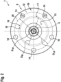
- the Figure 2 shows a plan view of the wheel bearing arrangement 1 in the axial direction, namely in the direction of the wheel bearing 2, of which only a part of the wheel hub 3 and the wheel flange can be seen here.
- the wheel holes 14 are arranged along a wheel bolt circle 25, which has a wheel bolt circle diameter D LK .
- the brake disk seat 16 has a brake disk seat diameter D BI with respect to the axis of rotation 6, this diameter preferably being determined at the point at which the outer circumferential surface 15 of the brake disk seat 16 merges into the contact surface 12.
- the wheel hub 3 has a toothing (not shown in detail here). This has a toothing diameter D VZ , which is indicated here.
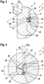
- the Figure 3 shows a detailed sectional view of an area of the wheel bearing arrangement 1, namely on the one hand through the wheel bearing 2, of which the inner ring, the outer ring 4 and one of the rolling elements 7 can be seen.
- the wheel hub 3 and the wheel flange are shown.
- the seal receiving space 20 with the seal 21 can be clearly seen.
- the seal receiving space 20 is delimited by an inner peripheral surface 26, a side surface 27 and a base surface 28. It is designed to be open at the edge in the direction of the outer ring 4, so it is essentially present as a channel or groove in the wheel flange.
- the side surface 27 is preferably arranged at least partially, in particular completely, in a plane that is perpendicular to the axis of rotation 6. It can be provided that the side surface 27 and the base surface 28 are connected to one another via a radius 29 or a curvature.
- the seal 21 has a first sealing lip 30, a second sealing lip 31 and a clamping fastening 32. The first sealing lip 30 rests on the side surface 27, the second sealing lip 31 on the base surface 28 and the clamping fastening 32 on the outer ring 4, in each case in a sealing manner.
- the recess 11 has a crank width B K which describes the distance between the contact surface 12 and the end surface 13 in the axial direction.
- the outer peripheral surface 15, which can form the brake disk seat 16, is spaced from the inner peripheral surface 26 by a flange cross-section Q F.
- the inner circumferential surface 26 and the outer circumferential surface 15 run parallel to one another, in particular continuously.
- the outer circumferential surface 15 is angled with respect to the axis of rotation 6, i.e. in the longitudinal section shown here it forms an angle with the axis of rotation which is greater than 0° and less than 180°.
- the Figure 4 shows a further detailed sectional view of the wheel bearing arrangement 1.
- the seal receiving space 20 has a seal receiving space height H D. This preferably describes the distance between the bottom surface 28 and the inner circumferential surface 26, namely the smallest distance present in the longitudinal section.
- a seal receiving space width B D can be seen, which describes the width of the seal receiving space 20 in the axial direction.
- the seal receiving space width B D corresponds to the extension of the inner circumferential surface 26 in the axial direction, in particular as seen in the longitudinal section.
- An air gap 33 with an air gap width B VD adjoins the seal receiving space 20.
- the air gap 33 is located in the axial direction in regions between the wheel flange and the outer ring 4, namely starting from the seal receiving space 20 in the radial direction outwards, preferably continuously.
Landscapes
- Engineering & Computer Science (AREA)
- Mechanical Engineering (AREA)
- General Engineering & Computer Science (AREA)
- Rolling Contact Bearings (AREA)
Description
- Die Erfindung betrifft eine Radlageranordnung für ein Kraftfahrzeug, mit einer Radnabe und einem Radlager zur drehbaren Lagerung der Radnabe an einem Radträger, wobei das Radlager einen Außenring und einen bezüglich des Außenrings um eine Drehachse drehbaren Innenring aufweist, der mit der Radnabe verbunden ist, wobei von der Radnabe ein Radflansch ausgeht, der eine in axialer Richtung gesehen in die von dem Außenring abgewandte Richtung offene Bremsscheibenaufnahme aufweist, die im Längsschnitt bezüglich der Drehachse gesehen durch einen Rücksprung des Radflanschs gebildet ist und eine Anlagefläche für eine Bremsscheibe aufweist, und wobei in dem Radflansch auf seiner dem Außenring in axialer Richtung zugewandten Seite ein Dichtungsaufnahmeraum ausgebildet ist, der in axialer Richtung eine Dichtungsaufnahmeraumbreite von größer oder gleich 2,0 mm aufweist.
- Eine derartige Radlageranordnung geht aus der Druckschrift
US 2 037 982 A hervor. - Aus der nicht vorveröffentlichte
EP 3 351 403 A1 geht eine Radlageranordnung hervor wobei von der Radnabe ein Radflansch ausgeht, der eine in axialer Richtung gesehen in die von dem Außenring abgewandte Richtung offene Bremsscheibenaufnahme aufweist, die durch einen Rücksprung des Radflanschs gebildet ist und eine Anlagefläche für eine Bremsscheibe aufweist, wobei in dem Radflansch ein Dichtungsaufnahmeraum ausgebildet ist, dadurch gekennzeichnet, wobei der Rücksprung des Radflanschs im Längsschnitt gesehen eine Kröpfungsbreite aufweist, und wobei eine Außenumfangsfläche des Radflanschs durch den Rücksprung einen Bremsscheibensitz bildet. - Die eingangs beschriebene Radlageranordnung dient der drehbaren Lagerung wenigstens eines Rads an einer Karosserie des Kraftfahrzeugs. Die Radlageranordnung ist dabei bevorzugt Bestandteil einer Radaufhängung, welche der Aufhängung, insbesondere der federnden Aufhängung, des Rads bezüglich der Karosserie dient. Das Rad ist an dem Radträger der Radlageranordnung drehbar gelagert. Hierzu ist das Rad an dem Radflansch befestigbar, welcher mit der Radnabe verbunden ist, die schlussendlich mittels des Radlagers an dem Radträger drehbar gelagert ist. Das Radlager verfügt über den Innenring und den Außenring. Es liegt als Wälzlager vor, insbesondere als einreihiges oder mehrreihiges Wälzlager, sodass zwischen dem Innenring und dem Außenring zur Reibungsreduzierung Wälzkörper angeordnet sind, die in nur einer oder mehreren Reihen angeordnet sind.
- Der Außenring ist an dem Radträger befestigt beziehungsweise befestigbar, während der Innenring mit der Radnabe und mithin dem Radflansch verbunden ist beziehungsweise mit ihr verbindbar ist. Der Innenring kann einstückig und/oder materialeinheitlich mit der Radnabe und/oder dem Radflansch ausgestaltet sein, insoweit also in diese integriert. Selbstverständlich können auch mehrere Innenringe vorgesehen sein, wobei einer oder mehrere dieser Innenringe separat von der Radnabe oder - alternativ - einstückig oder materialeinheitlich mit der Radnabe ausgeführt sein können. Es kann also wenigstens einer der Innenringe, zum Beispiel genau einer der Innenringe, in die Radnabe integriert sein, wohingegen ein anderer der Innenringe separat von dem Radflansch ausgebildet und nachfolgend an ihm befestigt wird.
- Es ist Aufgabe der Erfindung, eine Radlageranordnung für ein Kraftfahrzeug vorzuschlagen, welche gegenüber bekannten Radlageranordnungen Vorteile aufweist, insbesondere in axialer Richtung bezüglich der Drehachse schmal baut, insbesondere im Vergleich mit bekannten Radlageranordnungen. Bevorzugt ist die Radlageranordnung mit einem vorgegebenen Gelenkwellenflansch kombinierbar und entsprechend dimensionierbar. Der Gelenkwellenflansch liegt hierbei zum Beispiel in Form eines Gelenkwellenaußengelenks vor oder weist ein solches auf.
- Die Aufgabe wird erfindungsgemäß mit einer Radlageranordnung mit den Merkmalen des Anspruchs 1 erreicht.
- Erfindungsgemäß ist vorgesehen, dass der Rücksprung im Längsschnitt gesehen eine Kröpfungsbreite BK von größer oder gleich 5,0 mm aufweist, durch den Rücksprung eine Außenumfangsfläche des Radflanschs einen Bremsscheibensitz bildet, der bezüglich der Drehachse einen Bremsscheibensitzdurchmesser DBI aufweist, wobei das Verhältnis von Bremsscheibensitzdurchmesser DBI zu einer Außenringbreite BRL des Außenrings größer oder gleich 1,9 ist, und das Verhältnis von Bremsscheibensitzdurchmesser DBI zu einem Teilkreisdurchmesser DTK eines Teilkreises, auf dem
- Wälzkörper des Radlagers mit ihrem jeweiligen Drehpunkt angeordnet sind, größer oder gleich 1,2 ist.
- Eine bevorzugte Ausgestaltung der Erfindung sieht vor, dass die Außenumfangsfläche des Radflanschs von einer den Dichtungsaufnahmeraum in radialer Richtung nach außen begrenzenden Innenumfangsfläche um einen Flanschquerschnitt QF beabstandet ist, wobei der Flanschquerschnitt QF größer oder gleich 6,0 mm ist. Zusätzlich oder alternativ kann es vorgesehen sein, dass an dem Radflansch, insbesondere in der Bremsscheibenaufnahme, wenigstens eine Befestigungsmittelaufnahme auf einem Räderlochkreis mit einem Räderlochkreisdurchmesser DLK angeordnet ist, wobei das Verhältnis von Räderlochkreisdurchmesser DLK zu Teilkreisdurchmesser DTK größer oder gleich 1,4 ist.
- Von besonderer Bedeutung sind drei unterschiedliche Ausgestaltungen der in Anspruch 1 definierten Radlageranordnung:
- So umfasst in einer ersten Ausführungsform und einer zweiten Ausführungsform die Radlageranordnung sowohl die Radnabe und das Radlager als auch eine Gelenkwelle, welche den Gelenkwellenflansch aufweist. In der ersten Ausführungsform ist der Gelenkwellenflansch an der Radnabe befestigt und liegen die Flanschstirnseitenfläche des Gelenkwellenflanschs und die Radnabenstirnseitenfläche, welche bevorzugt durch eine Bördelung der Radnabe ausgebildet ist, aneinander an. Hierbei wird das Radlager gegen den Gelenkwellenflansch und/oder ein Gelenkwellenzapfen verspannt, beispielsweise mittels einer Schraube.
- In der zweiten Ausführungsform liegen die Flanschstirnseitenfläche des Gelenkwellenflanschs und die Radnabenstirnseitenfläche nicht aneinander an, sind also zumindest bereichsweise, insbesondere vollständig, voneinander beabstandet angeordnet. Bevorzugt liegt also zwischen den beiden Flächen ein Spalt vor. Eine derartige Ausgestaltung kann vorliegen, sofern das Radlager selbstragend ist, die Bördelung der Radnabe also für die Vorspannung ausreichend ist. Insoweit wird keine zusätzliche Vorspannung über eine Verspannung des Radlagers mit der Gelenkwelle beziehungsweise dem Gelenkwellenflansch realisiert.
- In einer dritten Ausführungsform der Radlageranordnung sind hingegen (nur) die Radnabe und das Radlager vorgesehen, wohingegen die Gelenkwelle beziehungsweise der Gelenkwellenflansch nicht vorliegt. Dies ist zum Beispiel für eine nicht angetriebene Radachse mit selbsttragendem Radlager der Fall.
- Es sind nun für die unterschiedlichen Ausgestaltungen der in Anspruch 1 definierten Radlageranordnung, also insbesondere die erste Ausführungsform, die zweite Ausführungsform oder die dritte Ausführungsform, zusätzlich zu den bereits definierten Parametern BD, BK, DBI, BRL, DTK, DLK und QF, soweit zutreffend, weitere Parameter vorgesehen:
- Zwischen der Flanschstirnseitenfläche und einem Beugepunkt des Gelenkwellenflanschs liegt in axialer Richtung ein Gelenkwellenflanschabstand AGW vor.
- Zwischen dem fahrzeuginnen liegenden Ende der Radnabe, insbesondere der Radnabenstirnseitenfläche, und der Anlagefläche in axialer Richtung liegt eine Lagereinheitsbreite BBS vor. Sich an den Dichtungsaufnahmeraum ein Luftspalt anschließt, der im Längsschnitt gesehen eine Luftspaltbreite BVD aufweist. Der lenflansch außenseitig einen Gelenkwellenflanschdurchmesser DGA aufweist. Der Gelenkwellenflansch einen Kugelkreisdurchmesser DGW aufweist. Der Außenring einen Radlageraußendurchmesser DRA aufweist. Die Radnabe in einer Flanschaufnahme für den Gelenkwellenflansch eine Verzahnung mit einem Verzahnungsdurchmesser DVZ aufweist. Der Dichtungsaufnahmeraum eine Dichtungsaufnahmeraumhöhe HD aufweist. Es ist nun für die unterschiedlichen Ausgestaltungen der in Anspruch 1 definierten Radlageranordnung, also insbesondere die erste Ausführungsform, die zweite Ausführungsform und/oder die dritte Ausführungsform, zusätzlich zu den bereits definierten Beziehungen, bevorzugt vorgesehen, dass das Verhältnis von Gelenkwellenflanschabstand AGW zu Lagereinheitsbreite BBS größer oder gleich 0,5 ist, und/oder dass das Verhältnis der Summe von Gelenkwellenflanschabstand AGW und Lagereinheitsbreite BBS zu Räderlochkreisdurchmesser DLK kleiner oder gleich 1,0 ist, und/oder dass das Verhältnis der Summe von Gelenkwellenflanschabstand AGW und Lagereinheitsbreite BBS zu Verzahnungsdurchmesser DVZ größer oder gleich 2,5 ist, und/oder dass das Verhältnis der Summe von Gelenkwellenflanschabstand AGW und Lagereinheitsbreite BBS zu Teilkreisdurchmesser DTK größer oder gleich 1,2 ist, und/oder dass das Verhältnis von Gelenkwellenflanschabstand AGW zu Teilkreisdurchmesser DTK kleiner oder gleich 0,6 ist, und/oder dass das Verhältnis von Bremsscheibensitzdurchmesser DBI zu Verzahnungsdurchmesser DVZ größer oder gleich 2,5 ist, und/oder dass das Verhältnis von Gelenkwellenflanschdurchmesser DGA zu Radlageraußendurchmesser DRA größer oder gleich 0,8 ist, und/oder dass das Verhältnis von Gelenkwellenflanschdurchmesser DGA zu Teilkreisdurchmesser DTK größer oder gleich 1,2 ist, und/oder dass das Verhältnis von Kugelkreisdurchmesser DGW zu Teilkreisdurchmesser DTK größer oder gleich 0,7 ist, und/oder dass das Verhältnis von Kugelkreisdurchmesser DGW zu Verzahnungsdurchmesser DVZ größer oder gleich 1,8 ist, und/oder dass das Verhältnis von Räderlochkreisdurchmesser DLK zu Außenringbreite BRL größer oder gleich 2,0 ist, und/oder dass das Verhältnis von Räderlochkreisdurchmesser DLK zu Verzahnungsdurchmesser DVZ größer oder gleich 3,3 ist, und/oder dass die Luftspaltbreite BVD kleiner oder gleich 2,0 mm ist.
- Zur besseren Übersichtlichkeit werden die erfindungsgemäßen sowie bevorzugten, in der vorangegangenen Beschreibung definierten Beziehungen nachfolgend verkürzt zusammengefasst:
- 1.

- 2.

- 3.

- 4.

- 5.

- 6.

- 7.

- 8.

- 9.

- 10.

- 11.

- 12.

- 13.

- 14.

- 15.

- 16. BD
- 17. BK
- 18. BVD
- 19. QF
- Für die Beziehungen gelten folgende vorteilhafte Wertebereiche:
- 1. größer oder gleich 0,6, insbesondere größer oder gleich 0,7;
- 2. kleiner oder gleich 0,95, besonders bevorzugt kleiner oder gleich 0,9,
- 3. größer oder gleich 2,75, besonders bevorzugt größer oder gleich 3;
- 4. größer oder gleich 1,3, besonders bevorzugt größer oder gleich 1,4;
- 5. kleiner oder gleich 0,55, besonders bevorzugt kleiner oder gleich 0,5;
- 6. größer oder gleich 2,0, besonders bevorzugt größer oder gleich 2,1;
- 7. größer oder gleich 1,3;
- 8. größer oder gleich 2,7, insbesondere bevorzugt größer oder gleich 2,9;
- 9. größer oder gleich 0,9, besonders bevorzugt größer oder gleich 1,0;
- 10. größer oder gleich 1,3, besonders bevorzugt größer oder gleich 1,4;
- 11. größer oder gleich 0,8, besonders bevorzugt größer oder gleich 0,9;
- 12. größer oder gleich 1,9, besonders bevorzugt größer oder gleich 2,0;
- 13. größer oder gleich 2,4, besonders bevorzugt größer oder gleich 2,8;
- 14. größer oder gleich 1,6, besonders bevorzugt größer oder gleich 1,7;
- 15. größer oder gleich 3,5, besonders bevorzugt größer oder gleich 3,7;
- 16. größer oder gleich 3,0 mm, besonders bevorzugt größer oder gleich 4,0 mm;
- 17. größer oder gleich 6,0 mm, besonders bevorzugt größer oder gleich 7,0 mm;
- 18. kleiner oder gleich 1,5 mm, besonders bevorzugt kleiner oder gleich 1,0 mm;
- 19. größer oder gleich 8,0 mm, besonders bevorzugt größer oder gleich 10,0 mm.
- Die erfindungsgemäße Radlageranordnung realisiert wenigstens die Beziehungen 6, 7, 16 und 17 mit dem jeweils zu dieser Beziehung gehörigen, in Anspruch 1 definierten Wert. Vorzugsweise sind alle der genannten Beziehungen mit den dazugehörigen Wert realisiert. Die jeweilige Beziehung bildet zusammen mit dem dazugehörigen Wert eine Bedingung. Sofern im Rahmen dieser Beschreibung von einer solchen die Rede ist, ist stets die entsprechende Beziehung mit dem jeweiligen Wert gemeint.
- Sofern im Rahmen dieser Beschreibung eine der genannten Bedingungen genannt wird, so ist darunter stets zu verstehen, dass der zu der entsprechenden Bedingung dazugehörige Wert ebenfalls mit einbezogen ist. Wird also rein beispielhaft erwähnt, dass die Bedingung 1 erfüllt sein soll, so wird nicht nur das Verhältnis von Gelenkwellenflanschabstand AGW zu Lagereinheitsbreite BBS bezeichnet, sondern es wird zugleich klargestellt, dass dieses Verhältnis größer oder gleich 0,5, insbesondere größer 0,5, bevorzugt größer oder gleich 0,6, besonders bevorzugt größer oder gleich 0,7 sein soll. Analog verhält es sich für die anderen Bedingungen beziehungsweise Beziehungen. Eingangs wurde bereits erwähnt, dass die Bremsscheibenaufnahme durch den Rücksprung des Radflanschs gebildet ist, sodass schlussendlich eine Kröpfung vorliegt und der Radflansch als gekröpfter Radflansch ausgestaltet ist. Zur Realisierung der Kröpfung ist insbesondere die in Anspruch 2 definierte Beziehung 14 mit dem dazugehörigen Wert von Bedeutung, sodass diese als besonders bedeutsam angesehen wird.
- Sofern die erfindungsgemäße Bedingungen und die Bedingung 14 erfüllt ist, ist es vorteilhaft, zusätzlich die Bedingung 15 zu erfüllen. Hieraus kann sich als vorteilhaftes Resultat die Bedingung 13 ergeben, weil die Außenringbreite BRL kleiner sein kann als üblich. Aus der Bedingung 13 ergibt sich zudem eine geringe Gesamtbreite der Radlageranordnung, also eine geringe Lagereinheitsbreite BBS bezogen auf das gegebene Gelenkwellenaußengelenk, was letztendlich das Ziel ist. Entsprechend ist vorteilhaft auch die Bedingung 1 erfüllt. Sind die erfindungsgemäße Bedingungen und die Bedingungen 1, 13, 14 und 15 erfüllt, so können zusätzlich oder alternativ wenigstens eine der Bedingungen 2, 3 und 4, vorzugsweise die Bedingungen 2 und 3, die Bedingungen 2 und 4 oder die Bedingungen 3 und 4, besonders bevorzugt die Bedingungen 2, 3 und 4, erfüllt sein.
- Weiterhin kann es sinnvoll sein, die Bedingung 18 zu erfüllen, um einen ausreichenden Freigang des Innenrings zu dem Außenring zu realisieren, sodass ein dynamisches Kippen der beiden gegeneinander ermöglich ist.
- Weil es vorteilhafterweise vorgesehen ist, bei einer gegebenen Dimensionierung des Gelenkwellenaußengelenks beziehungsweise des Gelenkwellenflanschs ein axial schmalbauendes Radlager beziehungsweise eine axial schmalbauende Radlageranordnung zu schaffen, ist es zudem vorteilhaft, zusätzlich die Bedingungen 5 und 9 bis 12, jeweils einzeln, in beliebiger Kombination miteinander oder alle, zu realisieren.
- Weitere vorteilhafte Ausgestaltungen der erfindungsgemäßen Radlageranordnung ergeben sich aus den Unteransprüchen.
- Eine bevorzugte Ausgestaltung der Erfindung sieht vor, dass die Innenumfangsfläche des Dichtungsaufnahmeraums und die Außenumfangsfläche des Radflanschs parallel zueinander verlaufen. Eine weitere, bevorzugte Ausgestaltung der Erfindung sieht vor, dass die Außenumfangsfläche des Radflanschs bezüglich der Drehachse angewinkelt ist. In einer weiteren bevorzugten Ausführungsform der Erfindung kann es vorgesehen sein, dass der Dichtungsaufnahmeraum von der Innenumfangsfläche, einer Seitenfläche und einer Bodenfläche begrenzt und in Richtung des Außenrings und der Wälzkörper randoffen ist.
- Eine weitere Ausführungsform der Erfindung sieht vor, dass die Seitenfläche in einer senkrecht auf der Drehachse stehenden Ebene liegt. Eine Weiterbildung sieht zudem vor, dass die Seitenfläche und die Bodenfläche im Längsschnitt gesehen über einen Radius miteinander verbunden sind. Eine weitere bevorzugte Ausführungsform der Erfindung sieht vor, dass die Außenumfangsfläche in den Räderlochkreis eingreift. Eine weitere bevorzugte Ausführungsform sieht vor, dass eine in dem Dichtungsaufnahmeraum angeordnete, insbesondere am Außenring geklemmte, Dichtung im Längsschnitt gesehen eine an der Seitenfläche anliegende erste Dichtlippe, eine an der Bodenfläche anliegende zweite Dichtlippe und (optional) wenigstens eine, bevorzugt an dem Außenring anliegende, Klemmbefestigung aufweist. Zusätzlich kann wenigstens eine weitere Dichtlippe an einer der genannten Flächen oder einer von diesen verschiedenen Fläche anliegen. Es können zudem mehrere weitere Dichtlippen vorliegen, die an derselben Fläche oder unterschiedlichen Flächen anliegen.
- Eine weitere Ausgestaltung der Erfindung sieht vor, dass das Radlager als mehrreihiges Wälzlager ausgestaltet ist. Schließlich kann im Rahmen einer weiteren Ausgestaltung der Erfindung vorgesehen sein, dass auf der der Anlagefläche für eine Bremsscheibe in axialer Richtung gegenüberliegenden Seite des Radflanschs wenigstens ein in Umfangsrichtung durchgehender oder wenigstens teilweise durchgehender Axialvorsprung ausgebildet ist.
- Die Erfindung wird nachfolgend anhand der in der Zeichnung dargestellten Ausführungsbeispiele näher erläutert, ohne dass eine Beschränkung der Erfindung erfolgt. Dabei zeigt
- Figur 1
- eine Längsschnittdarstellung durch einen Teil einer Radlageranordnung für ein Kraftfahrzeug,
- Figur 2
- eine Stirnseitenansicht der Radlageranordnung,
- Figur 3
- eine erste Detailschnittdarstellung durch die Radlageranordnung, sowie
- Figur 4
- eine zweite Detailschnittdarstellung durch die Radlageranordnung.
- Die
Figur 1 zeigt eine Längsschnittdarstellung durch einen Bereich einer Radlageranordnung 1, von welcher insbesondere ein Radlager 2 und eine Radnabe 3 dargestellt sind. Das Radlager 2 verfügt über einen Außenring 4. Weiterhin ist ein Gelenkwellenflansch 5 dargestellt. Der Längsschnitt durch die Radlageranordnung 1 liegt entlang einer Drehachse 6 der Radnabe 3, insbesondere bezüglich des Außenrings 4 vor. Das Radlager 2 ist als Wälzlager ausgestaltet, sodass zwischen einem Innenring des Radlagers 2 und dem Außenring 4 Wälzkörper 7 vorliegen. - In dem hier dargestellten Ausführungsbeispiel ist der Innenring in die Radnabe 3 integriert ausgebildet, sodass die Radnabe 3 selbst eine Lauffläche für einen oder mehrere der Wälzkörper 7 aufweist. Selbstverständlich kann der Innenring jedoch separat von der Radnabe 3 ausgestaltet sein. Zusätzlich zu dem Innenring ist ein nicht näher bezeichneter weiterer Innenring vorgesehen, der ebenfalls eine Lauffläche für wenigstens einen oder mehrere der Wälzkörper 7, insbesondere eine Reihe der Wälzkörper 7, aufweist. Der weitere Innenring ist durch die Ausbildung eines Wälznietbunds an der Radnabe 3 an dieser in axialer Richtung festgesetzt. Der Wälznietbund wird durch Aufweiten der Radnabe 3 in radialer Richtung hergestellt.
- Der Innenring und die an ihm angeordnete beziehungsweise befestigte Radnabe 3 sind in dem Außenring 4 angeordnet. Die Radnabe 3 ragt jedoch in axialer Richtung aus diesem heraus. Der in axialer Richtung über den Au-ßenring 4 überstehende Bereich der Radnabe 3 verläuft in radialer Richtung nach außen, sodass er im Längsschnitt gesehen den Außenring 4 in radialer Richtung zumindest teilweise übergreift, in dem hier dargestellten Ausführungsbeispiel vollständig, also zumindest teilweise in axialer Richtung benachbart zu dem Außenring 4 vorliegt. Der genannte Bereich dient als Radflansch und insoweit zur Befestigung der Rads an der Radnabe.
- Das Wälzlager liegt als mehrreihiges Wälzlager vor, sodass die Wälzkörper 7 in zwei in axialer Richtung bezüglich der Drehachse 6 voneinander beabstandete Wälzkörperreihen 8 und 9 aufgeteilt sind. Der Außenring 4 des Radlagers 2 ist bevorzugt an einem Radträger eines Kraftfahrzeugs befestigbar. An dem Radflansch und mithin der Radnabe 3 dagegen sind eine Bremsscheibe und ein Rad des Kraftfahrzeugs befestigbar, wobei die Befestigung des Rads an der Radnabe 3 über den Radflansch erfolgt.
- Zur Aufnahme der hier nicht dargestellten Bremsscheibe verfügt der Radflansch über eine Bremsscheibenaufnahme 10, die durch einen Rücksprung 11 des Radflanschs gebildet ist. Die Bremsscheibenaufnahme 10 liegt in radialer Richtung gesehen vorzugsweise zumindest bereichsweise in Überdeckung mit dem Außenring 4 vor. Die Bremsscheibenaufnahme 10 wird in axialer Richtung in Richtung des Außenrings 4 beziehungsweise der Wälzkörper 7 von einer Anlagefläche 12 begrenzt, die einem Anlegen beziehungsweise Abstützen der Bremsscheibe in axialer Richtung dient. Die Anlagefläche 12 liegt dabei auf der dem Außenring 4 in axialer Richtung abgewandten Seite des Radflanschs vor. Die Anlagefläche 12 ist gegenüber einer Stirnseitenfläche 13 des Radflanschs in axialer Richtung in Richtung des Außenrings 4 versetzt. Die Anlagefläche 12 und die Stirnseitenfläche 13 können zueinander parallel angeordnet sein oder jeweils vollständig in zueinander parallelen Ebenen liegen.
- Die Anlagefläche 12 wird von mehreren Radlöchern 14 durchgriffen, welche der Aufnahme von Radbolzen zur Befestigung des Rads beziehungsweise der Radnabe 3 dienen, Durch den Rücksprung 11 bildet eine Außenumfangsfläche 15 des Radflanschs einen Bremsscheibensitz 16 zur Abstützung der Bremsscheibe in radialer Richtung bezüglich der Drehachse 6. Die Außenumfangsfläche 15 ist vorzugsweise vollständig eben und ist bezüglich der Anlagefläche 12 angewinkelt, schließt mit dieser also einen Winkel ein, welcher größer ist als 0° und kleiner als 180°. Vorzugsweise ist der Winkel hierbei größer als 90° und kleiner als 180°.
- Vorstehend wurde bereits erwähnt, dass die Radlageranordnung 1 über den Gelenkwellenflansch 5 verfügt. Dieser ist in einer zentralen Flanschaufnahme 17 der Radnabe 3 angeordnet und bevorzugt formschlüssig und/oder kraftschlüssig mit der Radnabe 3 gekoppelt. In axialer Richtung stützt sich der Gelenkwellenflansch 5 mit einer Flanschstirnseitenfläche 18 an einer Radnabenstirnseitenfläche 19 der Radnabe 3 beziehungsweise des Wälznietbunds ab, liegt also an dieser an, insbesondere vollflächig. Die Flanschstirnseitenfläche 18 und die Radnabenstirnseitenfläche 19 der Radnabe 3 beziehungsweise des Wälznietbunds sind insoweit jeweils wenigstens bereichsweise eben und liegen mit ihren ebenen Bereichen nach einer Montage der Radlageranordnung 1 aneinander an. Es ist erkennbar, dass die Radnabe 3 in axialer Richtung einerseits von der Stirnseitenfläche 13 und andererseits von der Radnabenstirnseitenfläche 19 der Radnabe 3, insbesondere des Wälznietbunds der Radnabe 3, begrenzt ist. Diese definieren insoweit die maximale Erstreckung der Radnabe 3 in axialer Richtung.
- Der Radflansch weist auf seiner dem Außenring 4 zugewandten Seite einen Dichtungsaufnahmeraum 20 auf, in welchem eine Dichtung 21 angeordnet ist. Die Dichtung 21 liegt einerseits, insbesondere rotierbar beziehungsweise rotierend, dichtend an dem Radflansch und andererseits, insbesondere drehfest, dichtend an dem Außenring 4 an, sodass das Radlager 2 gegenüber einer Außenumgebung zuverlässig abgedichtet ist. Eine weitere Dichtung 22 ist auf der der Dichtung 21 in axialer Richtung abgewandten Seite des Radlagers 2 angeordnet, nämlich auf der der Dichtung 21 gegenüberliegenden Seite der Wälzkörper 7.
- Es ist ersichtlich, dass zwischen der Flanschstirnseitenfläche 18 und einem Beugepunkt des Gelenkwellenflanschs 5 ein Gelenkwellenflanschabstand AGW vorliegt. Weiterhin ist zwischen der Anlagefläche 12 und der Radnabenstirnseitenfläche 19 der Radnabe 3, insbesondere des Wälznietbunds, eine Lagereinheitsbreite BBS vorgesehen. Es wird deutlich, dass der Gelenkwellenflanschabstand AGW und die Lagereinheitsbreite BBS bei montierter Radlageranordnung 1 in axialer Richtung unmittelbar aneinander angrenzen, also eine gemeinsame Grenze aufweisen. Weiterhin wird deutlich, dass der Außenring 4 eine Außenringbreite BRL aufweist.
- Der Gelenkwellenflansch 5 weist außenseitig einen Gelenkwellenflanschdurchmesser DGA auf. Zudem verfügt er über einen Kugelkreisdurchmesser DGW. Der Außenring 4 weist einen Radlageraußendurchmesser DRA auf. Dieser Außendurchmesser bezeichnet den Durchmesser einer Sitzfläche 24, welche in einem Sitz des hier nicht dargestellten Radträgers angeordnet werden kann und entsprechend das Radlager 2 beziehungsweise den Au-ßenring 4 in radialer Richtung bezüglich des Radträgers abstützt. Die Wälzkörper 7 des Radlagers 2 sind mit ihrem jeweiligen Drehpunkt auf einem Teilkreis mit einem Teilkreisdurchmesser DTK angeordnet. Die Wälzkörper 7 selbst weisen einen Wälzkörperdurchmesser DK auf.
- Die
Figur 2 zeigt eine Draufsicht auf die Radlageranordnung 1 in axialer Richtung, nämlich in Richtung des Radlagers 2, von welchem hier lediglich ein Teil der Radnabe 3 und der Radflansch erkennbar ist. Es wird deutlich, dass mehrere Radlöcher 14 vorgesehen sind, welche vorzugsweise gleichmäßig in Umfangsrichtung verteilt angeordnet sind. Die Radlöcher 14 sind entlang eines Räderlochkreises 25 angeordnet, welcher einen Räderlochkreisdurchmesser DLK aufweist. Der Bremsscheibensitz 16 weist bezüglich der Drehachse 6 einen Bremsscheibensitzdurchmesser DBI auf, wobei dieser Durchmesser vorzugsweise an derjenigen Stelle bestimmt wird, an welcher die Außenumfangsfläche 15 des Bremsscheibensitzes 16 in die Anlagefläche 12 übergeht. In der Flanschaufnahme 17 weist die Radnabe 3 eine hier nicht im Detail dargestellte Verzahnung auf. Diese weist einen Verzahnungsdurchmesser DVZ auf, welcher hier angedeutet ist. - Die
Figur 3 zeigt eine Detailschnittdarstellung eines Bereichs der Radlageranordnung 1, nämlich zum einen durch das Radlager 2, von welchem der Innenring, der Außenring 4 und einer der Wälzkörper 7 erkennbar sind. Zum anderen sind die Radnabe 3 und der Radflansch dargestellt. Deutlich zu erkennen ist der Dichtungsaufnahmeraum 20 mit der Dichtung 21. Der Dichtungsaufnahmeraum 20 wird von einer Innenumfangsfläche 26, einer Seitenfläche 27 sowie einer Bodenfläche 28 begrenzt. Er ist in Richtung des Außenrings 4 randoffen ausgestaltet, liegt also im Wesentlichen als Kanal beziehungsweise Rinne in dem Radflansch vor. - Vorzugsweise ist die Seitenfläche 27 zumindest teilweise, insbesondere vollständig, in einer senkrecht auf der Drehachse 6 stehenden Ebene angeordnet. Es kann vorgesehen sein, dass die Seitenfläche 27 und die Bodenfläche 28 über einen Radius 29 beziehungsweise eine Krümmung miteinander verbunden sind. Die Dichtung 21 verfügt über eine erste Dichtlippe 30, eine zweite Dichtlippe 31 sowie eine Klemmbefestigung 32. Die erste Dichtlippe 30 liegt an der Seitenfläche 27, die zweite Dichtlippe 31 an der Bodenfläche 28 und die Klemmbefestigung 32 an dem Außenring 4 an, jeweils dichtend. Es ist erkennbar, dass der Rücksprung 11 eine Kröpfungsbereite BK aufweist, welche den Abstand zwischen der Anlagefläche 12 und der Stirnseitenfläche 13 in axialer Richtung beschreibt. Weiterhin wird deutlich, dass die Außenumfangsfläche 15, die den Bremsscheibensitz 16 bilden kann, um einen Flanschquerschnitt QF von der Innenumfangsfläche 26 beabstandet ist. Besonders bevorzugt verlaufen hierbei die Innenumfangsfläche 26 und die Außenumfangsfläche 15 parallel zueinander, insbesondere durchgehend. Die Außenumfangsfläche 15 ist hierbei bezüglich der Drehachse 6 angewinkelt, schließt also in dem hier dargestellten Längsschnitt mit der Drehachse einen Winkel ein, welcher größer als 0° und kleiner als 180° ist.
- Die
Figur 4 zeigt eine weitere Detailschnittdarstellung der Radlageranordnung 1. Es ist erkennbar, dass der Dichtungsaufnahmeraum 20 eine Dichtungsaufnahmeraumhöhe HD aufweist. Diese beschreibt vorzugsweise den Abstand zwischen der Bodenfläche 28 und der Innenumfangsfläche 26, nämlich den im Längsschnitt vorliegenden kleinsten Abstand. Weiterhin ist eine Dichtungsaufnahmeraumbreite BD zu erkennen, welche die Breite des Dichtungsaufnahmeraums 20 in axialer Richtung beschreibt. Bevorzugt entspricht die Dichtungsaufnahmeraumbreite BD der Erstreckung der Innenumfangsfläche 26 in axialer Richtung, insbesondere im Längsschnitt gesehen. An den Dichtungsaufnahmeraum 20 schließt sich ein Luftspalt 33 mit einer Luftspaltbreite BVD an. Der Luftspalt 33 liegt in axialer Richtung bereichsweise zwischen dem Radflansch und dem Außenring 4 vor, nämlich ausgehend von dem Dichtungsaufnahmeraum 20 in radialer Richtung nach außen, vorzugweise durchgehend. - Für die genannten Abmessungen und Größen gelten besonders bevorzugt die eingangs bereits erwähnten Werte. Werden die ebenfalls eingangs beschriebenen Bedingungen erfüllt, liegen diese also innerhalb des jeweils beschriebenen Wertebereichs, so kann die Dichtung 21 ohne weiteres in den Radflansch integriert werden, nämlich auf die dargestellte Art und Weise. Somit lässt sich eine äußerst kompakte Radlageranordnung 1 realisieren.
Claims (11)
- Radlageranordnung (1) für ein Kraftfahrzeug mit einer Radnabe (3) und einem als Wälzlager ausgestalteten Radlager (2) zur drehbaren Lagerung der Radnabe (3) an einem Radträger, wobei das Radlager (2) Wälzkörper (7), einen Außenring (4) und einen bezüglich des Außenrings (4) um eine Drehachse (6) drehbaren Innenring aufweist, der mit der Radnabe (3) verbunden ist, wobei von der Radnabe (3) ein Radflansch ausgeht, der eine in axialer Richtung gesehen in die von dem Außenring (4) abgewandte Richtung offene Bremsscheibenaufnahme (10) aufweist, die im Längsschnitt bezüglich der Drehachse (6) gesehen durch einen Rücksprung (11) des Radflanschs gebildet ist und eine Anlagefläche (12) für eine Bremsscheibe aufweist, und wobei- in dem Radflansch auf seiner dem Außenring (4) in axialer Richtung zugewandten Seite ein Dichtungsaufnahmeraum (20) ausgebildet ist, der in axialer Richtung eine Dichtungsaufnahmeraumbreite (BD) von größer oder gleich 2,0 mm aufweist,dadurch gekennzeichnet, dass- der Rücksprung (11) des Radflanschs im Längsschnitt gesehen eine Kröpfungsbreite (BK) von größer oder gleich 5,0 mm aufweist,- durch den Rücksprung (11) des Radflanschs eine Außenumfangsfläche (15) des Radflanschs einen Bremsscheibensitz (16) bildet, der bezüglich der Drehachse (6) einen Bremsscheibensitzdurchmesser (DBI) aufweist, wobei das Verhältnis von Bremsscheibensitzdurchmesser (DBI) zu einer Au-ßenringbreite (BRL) des Außenrings (4) größer oder gleich 1,9 ist, und- das Verhältnis von Bremsscheibensitzdurchmesser (DBI) zu einem Teilkreisdurchmesser (DTK) eines Teilkreises, auf dem Wälzkörper (7) des Radlagers (2) mit ihrem jeweiligen Drehpunkt angeordnet sind, größer oder gleich 1,2 ist.
- Radlageranordnung nach Anspruch 1, dadurch gekennzeichnet, dass- an dem Radflansch, insbesondere in der Bremsscheibenaufnahme (10), wenigstens eine Befestigungsmittelaufnahme (14) auf einem Räderlochkreis (25) mit einem Räderlochkreisdurchmesser (DLK) angeordnet ist, wobei- das Verhältnis von Räderlochkreisdurchmesser (DLK) zu Teilkreisdurchmesser (DTK) größer oder gleich 1,4 ist.
- Radlageranordnung nach einem der vorhergehenden Ansprüche,
dadurch gekennzeichnet, dass- die Außenumfangsfläche (15) des Radflanschs von einer den Dichtungsaufnahmeraum (20) in radialer Richtung nach außen begrenzenden Innenumfangsfläche (26) um einen Flanschquerschnitt (QF) beabstandet ist, wobei- der Flanschquerschnitt (QF) größer oder gleich 6,0 mm ist. - Radlageranordnung nach Anspruch 3, dadurch gekennzeichnet, dass die Innenumfangsfläche (26) des Dichtungsaufnahmeraums (20) und die Außenumfangsfläche (15) des Radflanschs parallel zueinander verlaufen.
- Radlageranordnung nach einem der vorhergehenden Ansprüche,
dadurch gekennzeichnet, dass die Außenumfangsfläche (15) des Radflanschs bezüglich der Drehachse (6) angewinkelt ist. - Radlageranordnung nach Anspruch 3 oder 4, dadurch gekennzeichnet, dass der Dichtungsaufnahmeraum (20) von der Innenumfangsfläche (26), einer Seitenfläche (27) und einer Bodenfläche (28) begrenzt und in Richtung des Außenrings (4) und der Wälzkörper (7) randoffen ist.
- Radlageranordnung nach Anspruch 6, dadurch gekennzeichnet, dass die Seitenfläche (27) in einer senkrecht auf der Drehachse (6) stehenden Ebene liegt.
- Radlageranordnung nach Anspruch 6 oder 7, dadurch gekennzeichnet, dass die Seitenfläche (27) und die Bodenfläche (28) im Längsschnitt gesehen über einen Radius miteinander verbunden sind.
- Radlageranordnung nach Anspruch 2, dadurch gekennzeichnet, dass die Außenumfangsfläche (15) in den Räderlochkreis (25) eingreift.
- Radlageranordnung nach einem der Ansprüche 6 bis 8, dadurch gekennzeichnet, dass eine in dem Dichtungsaufnahmeraum (20) angeordnete Dichtung (21) im Längsschnitt gesehen eine an der Seitenfläche (27) anliegende erste Dichtlippe (30), eine an der Bodenfläche (28) anliegende zweite Dichtlippe (31) und eine an dem Außenring (4) anliegende Klemmbefestigung (32) aufweist.
- Radlageranordnung nach einem der vorhergehenden Ansprüche, dadurch gekennzeichnet, dass das Radlager (2) als mehrreihiges Wälzlager ausgestaltet ist.
Applications Claiming Priority (1)
| Application Number | Priority Date | Filing Date | Title |
|---|---|---|---|
| DE102017204203.6A DE102017204203A1 (de) | 2017-03-14 | 2017-03-14 | Radlageranordnung für ein Kraftfahrzeug |
Publications (2)
| Publication Number | Publication Date |
|---|---|
| EP3447321A1 EP3447321A1 (de) | 2019-02-27 |
| EP3447321B1 true EP3447321B1 (de) | 2024-05-08 |
Family
ID=59256104
Family Applications (1)
| Application Number | Title | Priority Date | Filing Date |
|---|---|---|---|
| EP18159814.5A Active EP3447321B1 (de) | 2017-03-14 | 2018-03-02 | Mit einem gleichlaufgelenk verbundene radnaben-wälzlageranordnung für ein kraftfahrzeug mit einer dichtungsvorrichtung |
Country Status (4)
| Country | Link |
|---|---|
| US (1) | US11117421B2 (de) |
| EP (1) | EP3447321B1 (de) |
| CN (1) | CN108569083A (de) |
| DE (1) | DE102017204203A1 (de) |
Families Citing this family (3)
| Publication number | Priority date | Publication date | Assignee | Title |
|---|---|---|---|---|
| DE102018131876A1 (de) * | 2018-12-12 | 2020-06-18 | Schaeffler Technologies AG & Co. KG | Bremssystem mit mehreren Druckkolben für eine elektrische Radantriebseinheit; sowie Radantriebseinheit |
| KR102522632B1 (ko) * | 2019-01-16 | 2023-04-24 | 주식회사 일진글로벌 | 차량용 휠베어링 |
| DE102019205782B4 (de) | 2019-04-23 | 2022-04-28 | Audi Ag | Radlageranordnung für ein Kraftfahrzeug |
Family Cites Families (24)
| Publication number | Priority date | Publication date | Assignee | Title |
|---|---|---|---|---|
| US2037982A (en) * | 1933-02-23 | 1936-04-21 | Gen Motors Corp | Bearing and bearing mounting |
| NL169630C (nl) | 1972-04-18 | 1982-08-02 | Skf Ind Trading & Dev | Uitwisselbare lagereenheid. |
| NL171739C (nl) * | 1973-02-09 | 1983-05-02 | Skf Ind Trading & Dev | Lager met een binnen- en een buitenloopring, die een geheel vormen met bevestigingsflenzen. |
| FR2693272B1 (fr) * | 1992-07-03 | 1994-09-02 | Skf France | Dispositif de détection de la vitesse de rotation d'un palier à roulement et moyeu à roulement pour roue de véhicule équipé d'un tel dispositif. |
| US5813675A (en) * | 1995-10-31 | 1998-09-29 | The Timken Company | Multibarrier seal |
| CN2411135Y (zh) | 1999-12-31 | 2000-12-20 | 万向钱潮股份有限公司 | 驱动轮轮毂轴承组件 |
| US6666303B2 (en) | 2000-07-04 | 2003-12-23 | Ntn Corporation | Wheel bearing assembly |
| JP2003240003A (ja) * | 2002-02-18 | 2003-08-27 | Nsk Ltd | 軸受用シール、シール付軸受およびハブユニット軸受 |
| JP2003262231A (ja) * | 2002-03-08 | 2003-09-19 | Nsk Ltd | 転がり軸受用シール、シール付軸受及びハブユニット軸受 |
| JP4200705B2 (ja) * | 2002-08-02 | 2008-12-24 | 日本精工株式会社 | シールリング付転がり軸受ユニット |
| US7044563B2 (en) | 2003-11-07 | 2006-05-16 | Nsk Corporation | Wheel supporting roller bearing unit and manufacturing method of the same |
| JP2005147298A (ja) * | 2003-11-18 | 2005-06-09 | Ntn Corp | 車輪用軸受装置 |
| JP4484104B2 (ja) | 2004-08-16 | 2010-06-16 | Ntn株式会社 | 車輪用軸受装置 |
| JP5376211B2 (ja) | 2008-08-08 | 2013-12-25 | 株式会社ジェイテクト | 転がり軸受装置 |
| JP5327590B2 (ja) * | 2008-09-12 | 2013-10-30 | 株式会社ジェイテクト | 転がり軸受装置 |
| JP2010106925A (ja) * | 2008-10-29 | 2010-05-13 | Jtekt Corp | 転がり軸受装置 |
| CN104290538B (zh) | 2009-12-21 | 2016-12-07 | Ntn株式会社 | 车轮用轴承装置 |
| DE102011003704B4 (de) * | 2011-02-07 | 2018-09-13 | Schaeffler Technologies AG & Co. KG | Labyrinthdichtung eines Radiallagers mit Radialflansch |
| JP6007515B2 (ja) | 2012-03-02 | 2016-10-12 | 株式会社ジェイテクト | 車輪支持装置 |
| ITTO20120605A1 (it) | 2012-07-09 | 2014-01-10 | Skf Ab | Gruppo cuscinetto-mozzo con dispositivo di tenuta |
| DE102013217299B4 (de) * | 2013-08-30 | 2018-09-13 | Schaeffler Technologies AG & Co. KG | Dichtungsanordnung mit einem Schleuderring für ein Wälzlager |
| DE102014204334A1 (de) | 2014-03-10 | 2015-09-10 | Schaeffler Technologies AG & Co. KG | Radlagereinheit |
| DE102015211456A1 (de) | 2015-06-22 | 2016-12-22 | Ford Global Technologies, Llc | Radmodul für eine angetriebene Achse eines Kraftfahrzeugs |
| DE102017200338A1 (de) * | 2017-01-11 | 2017-04-27 | Audi Ag | Radlager für ein Kraftfahrzeug |
-
2017
- 2017-03-14 DE DE102017204203.6A patent/DE102017204203A1/de not_active Withdrawn
-
2018
- 2018-03-02 EP EP18159814.5A patent/EP3447321B1/de active Active
- 2018-03-13 US US15/919,597 patent/US11117421B2/en active Active
- 2018-03-14 CN CN201810209564.4A patent/CN108569083A/zh active Pending
Also Published As
| Publication number | Publication date |
|---|---|
| US20180264879A1 (en) | 2018-09-20 |
| CN108569083A (zh) | 2018-09-25 |
| DE102017204203A1 (de) | 2017-07-20 |
| EP3447321A1 (de) | 2019-02-27 |
| US11117421B2 (en) | 2021-09-14 |
Similar Documents
| Publication | Publication Date | Title |
|---|---|---|
| DE10331936B4 (de) | Radlagereinheit in Schrägkugellagerausführung | |
| DE10125253B4 (de) | Dichtvorrichtung für Flanschlager | |
| DE2248012C2 (de) | Zweireihiges Radial-Axial-Wälzlager | |
| EP3447321B1 (de) | Mit einem gleichlaufgelenk verbundene radnaben-wälzlageranordnung für ein kraftfahrzeug mit einer dichtungsvorrichtung | |
| DE112007002695T5 (de) | Radlagervorrichtung für ein Fahrzeug | |
| DE112008002994T5 (de) | Dichtungsvorrichtung für Lageranordnung und Radstützlageranordnung mit dieser | |
| EP3314136B1 (de) | Wälzlagereinheit | |
| EP2350478B1 (de) | Vorrichtung zur verdrehbaren kopplung zweier koaxialer anschlusselemente | |
| DE10137127B4 (de) | Radlager-Einheit für Kraftfahrzeugrad | |
| DE102016214350A1 (de) | Verfahren und Vorrichtung zur Herstellung eines Schrägrollenlagers | |
| DE102016207215A1 (de) | Montageverfahren einer Nabenlagereinheit | |
| EP3959083B1 (de) | Radlageranordnung für ein kraftfahrzeug | |
| DE2626170C3 (de) | Differentialgetriebe mit kombiniert gelagerten Zentralrädern | |
| EP1704339A1 (de) | Aussenring eines radlagers und axiale sicherung des aussenringes | |
| DE102006040776B4 (de) | Wälzlager | |
| EP1912800B1 (de) | Radlagereinheit | |
| DE102004055786A1 (de) | Radlagereinheit | |
| DE10325584A1 (de) | Radlagervorrichtung | |
| DE2463071C2 (de) | Lagereinheit | |
| EP1694518A1 (de) | Radlagermodul in einem radträger | |
| DE202018102280U1 (de) | Lager einer Nabeneinheit | |
| DE102004059518A1 (de) | Schrägwälzlager, insbesondere für eine Radlagereinheit eines Kraftfahrzeuges | |
| DE60026431T2 (de) | Dichtungseinrichtung für ein Wälzlager | |
| EP1694974B1 (de) | Radlager in einem radträger | |
| DE112020000263B4 (de) | Fahrzeugradlager |
Legal Events
| Date | Code | Title | Description |
|---|---|---|---|
| PUAI | Public reference made under article 153(3) epc to a published international application that has entered the european phase |
Free format text: ORIGINAL CODE: 0009012 |
|
| STAA | Information on the status of an ep patent application or granted ep patent |
Free format text: STATUS: THE APPLICATION HAS BEEN PUBLISHED |
|
| AK | Designated contracting states |
Kind code of ref document: A1 Designated state(s): AL AT BE BG CH CY CZ DE DK EE ES FI FR GB GR HR HU IE IS IT LI LT LU LV MC MK MT NL NO PL PT RO RS SE SI SK SM TR |
|
| AX | Request for extension of the european patent |
Extension state: BA ME |
|
| STAA | Information on the status of an ep patent application or granted ep patent |
Free format text: STATUS: REQUEST FOR EXAMINATION WAS MADE |
|
| 17P | Request for examination filed |
Effective date: 20190827 |
|
| RBV | Designated contracting states (corrected) |
Designated state(s): AL AT BE BG CH CY CZ DE DK EE ES FI FR GB GR HR HU IE IS IT LI LT LU LV MC MK MT NL NO PL PT RO RS SE SI SK SM TR |
|
| STAA | Information on the status of an ep patent application or granted ep patent |
Free format text: STATUS: EXAMINATION IS IN PROGRESS |
|
| 17Q | First examination report despatched |
Effective date: 20220317 |
|
| P01 | Opt-out of the competence of the unified patent court (upc) registered |
Effective date: 20230529 |
|
| GRAP | Despatch of communication of intention to grant a patent |
Free format text: ORIGINAL CODE: EPIDOSNIGR1 |
|
| STAA | Information on the status of an ep patent application or granted ep patent |
Free format text: STATUS: GRANT OF PATENT IS INTENDED |
|
| RIC1 | Information provided on ipc code assigned before grant |
Ipc: B60B 27/06 20060101ALN20231201BHEP Ipc: F16C 19/18 20060101ALN20231201BHEP Ipc: F16D 65/12 20060101ALI20231201BHEP Ipc: F16D 3/223 20110101ALI20231201BHEP Ipc: B60B 35/18 20060101ALI20231201BHEP Ipc: B60B 27/00 20060101ALI20231201BHEP Ipc: F16C 33/58 20060101ALI20231201BHEP Ipc: F16C 33/78 20060101AFI20231201BHEP |
|
| INTG | Intention to grant announced |
Effective date: 20231220 |
|
| GRAS | Grant fee paid |
Free format text: ORIGINAL CODE: EPIDOSNIGR3 |
|
| GRAA | (expected) grant |
Free format text: ORIGINAL CODE: 0009210 |
|
| STAA | Information on the status of an ep patent application or granted ep patent |
Free format text: STATUS: THE PATENT HAS BEEN GRANTED |
|
| AK | Designated contracting states |
Kind code of ref document: B1 Designated state(s): AL AT BE BG CH CY CZ DE DK EE ES FI FR GB GR HR HU IE IS IT LI LT LU LV MC MK MT NL NO PL PT RO RS SE SI SK SM TR |
|
| REG | Reference to a national code |
Ref country code: GB Ref legal event code: FG4D Free format text: NOT ENGLISH |
|
| REG | Reference to a national code |
Ref country code: CH Ref legal event code: EP |
|
| REG | Reference to a national code |
Ref country code: DE Ref legal event code: R096 Ref document number: 502018014583 Country of ref document: DE |