EP3447198B1 - Display device for a shovel - Google Patents
Display device for a shovel Download PDFInfo
- Publication number
- EP3447198B1 EP3447198B1 EP17786044.2A EP17786044A EP3447198B1 EP 3447198 B1 EP3447198 B1 EP 3447198B1 EP 17786044 A EP17786044 A EP 17786044A EP 3447198 B1 EP3447198 B1 EP 3447198B1
- Authority
- EP
- European Patent Office
- Prior art keywords
- shovel
- display area
- operation analysis
- display device
- displayed
- Prior art date
- Legal status (The legal status is an assumption and is not a legal conclusion. Google has not performed a legal analysis and makes no representation as to the accuracy of the status listed.)
- Active
Links
- 238000004458 analytical method Methods 0.000 claims description 136
- 230000006872 improvement Effects 0.000 claims description 33
- 239000010720 hydraulic oil Substances 0.000 description 19
- 239000003921 oil Substances 0.000 description 13
- 239000000446 fuel Substances 0.000 description 10
- 238000010586 diagram Methods 0.000 description 9
- 238000000034 method Methods 0.000 description 8
- 238000001514 detection method Methods 0.000 description 7
- XLYOFNOQVPJJNP-UHFFFAOYSA-N water Substances O XLYOFNOQVPJJNP-UHFFFAOYSA-N 0.000 description 7
- 238000009412 basement excavation Methods 0.000 description 6
- 239000002826 coolant Substances 0.000 description 6
- 230000008569 process Effects 0.000 description 6
- 230000001133 acceleration Effects 0.000 description 5
- 238000006243 chemical reaction Methods 0.000 description 4
- 230000007423 decrease Effects 0.000 description 4
- 230000007246 mechanism Effects 0.000 description 4
- 230000006870 function Effects 0.000 description 3
- 230000008859 change Effects 0.000 description 2
- 238000006073 displacement reaction Methods 0.000 description 2
- 230000007935 neutral effect Effects 0.000 description 2
- 230000004044 response Effects 0.000 description 2
- 230000000630 rising effect Effects 0.000 description 2
- 241000283973 Oryctolagus cuniculus Species 0.000 description 1
- 241000270666 Testudines Species 0.000 description 1
- 230000001413 cellular effect Effects 0.000 description 1
- 238000010276 construction Methods 0.000 description 1
- 230000001186 cumulative effect Effects 0.000 description 1
- 230000000694 effects Effects 0.000 description 1
- 239000012530 fluid Substances 0.000 description 1
- 239000002828 fuel tank Substances 0.000 description 1
- 238000002347 injection Methods 0.000 description 1
- 239000007924 injection Substances 0.000 description 1
- 239000004973 liquid crystal related substance Substances 0.000 description 1
- 238000012423 maintenance Methods 0.000 description 1
- 239000013642 negative control Substances 0.000 description 1
- 238000012545 processing Methods 0.000 description 1
- 239000004065 semiconductor Substances 0.000 description 1
- 238000005507 spraying Methods 0.000 description 1
- 239000007858 starting material Substances 0.000 description 1
Images


Classifications
-
- E—FIXED CONSTRUCTIONS
- E02—HYDRAULIC ENGINEERING; FOUNDATIONS; SOIL SHIFTING
- E02F—DREDGING; SOIL-SHIFTING
- E02F9/00—Component parts of dredgers or soil-shifting machines, not restricted to one of the kinds covered by groups E02F3/00 - E02F7/00
- E02F9/26—Indicating devices
- E02F9/264—Sensors and their calibration for indicating the position of the work tool
- E02F9/265—Sensors and their calibration for indicating the position of the work tool with follow-up actions (e.g. control signals sent to actuate the work tool)
-
- E—FIXED CONSTRUCTIONS
- E02—HYDRAULIC ENGINEERING; FOUNDATIONS; SOIL SHIFTING
- E02F—DREDGING; SOIL-SHIFTING
- E02F9/00—Component parts of dredgers or soil-shifting machines, not restricted to one of the kinds covered by groups E02F3/00 - E02F7/00
- E02F9/26—Indicating devices
-
- E—FIXED CONSTRUCTIONS
- E02—HYDRAULIC ENGINEERING; FOUNDATIONS; SOIL SHIFTING
- E02F—DREDGING; SOIL-SHIFTING
- E02F9/00—Component parts of dredgers or soil-shifting machines, not restricted to one of the kinds covered by groups E02F3/00 - E02F7/00
- E02F9/20—Drives; Control devices
- E02F9/2058—Electric or electro-mechanical or mechanical control devices of vehicle sub-units
- E02F9/2095—Control of electric, electro-mechanical or mechanical equipment not otherwise provided for, e.g. ventilators, electro-driven fans
-
- E—FIXED CONSTRUCTIONS
- E02—HYDRAULIC ENGINEERING; FOUNDATIONS; SOIL SHIFTING
- E02F—DREDGING; SOIL-SHIFTING
- E02F9/00—Component parts of dredgers or soil-shifting machines, not restricted to one of the kinds covered by groups E02F3/00 - E02F7/00
- E02F9/26—Indicating devices
- E02F9/261—Surveying the work-site to be treated
-
- E—FIXED CONSTRUCTIONS
- E02—HYDRAULIC ENGINEERING; FOUNDATIONS; SOIL SHIFTING
- E02F—DREDGING; SOIL-SHIFTING
- E02F9/00—Component parts of dredgers or soil-shifting machines, not restricted to one of the kinds covered by groups E02F3/00 - E02F7/00
- E02F9/26—Indicating devices
- E02F9/267—Diagnosing or detecting failure of vehicles
- E02F9/268—Diagnosing or detecting failure of vehicles with failure correction follow-up actions
-
- H—ELECTRICITY
- H04—ELECTRIC COMMUNICATION TECHNIQUE
- H04N—PICTORIAL COMMUNICATION, e.g. TELEVISION
- H04N7/00—Television systems
- H04N7/18—Closed-circuit television [CCTV] systems, i.e. systems in which the video signal is not broadcast
- H04N7/181—Closed-circuit television [CCTV] systems, i.e. systems in which the video signal is not broadcast for receiving images from a plurality of remote sources
Definitions
- the present invention relates to display devices for shovels.
- Patent Document 1 A display device that displays a determination as to the appropriateness of fuel efficiency with respect to an operation on a construction machine is known (for example, Patent Document 1).
- Patent Document 1 Japanese Unexamined Patent Publication No. 2008-240361
- Patent Document 1 The display device of Patent Document 1, however, merely displays a determination as to the appropriateness of fuel efficiency. An operator therefore cannot understand how the fuel efficiency has been affected by what operations of the operator. The operator therefore cannot understand what specific operations to perform to make it possible to improve the operator's operating efficiency.
- a display device for a shovel which is a display device for a shovel with an attachment including a boom, an arm, and an end attachment, includes an operation analysis start input part for starting an operation analysis of the shovel and storing the history of the operation analysis and an operation analysis check input part for displaying the result of the operation analysis and an operation history of the shovel on a same screen.
- FIG. 1 is a side view of a shovel (an excavator) according to an embodiment of the present invention.
- An upper turning body 3 is turnably mounted on a lower traveling body 1 of the shovel via a turning mechanism 2.
- a boom 4 is attached to the upper turning body 3.
- An arm 5 is attached to an end of the boom 4.
- a bucket 6 serving as an end attachment is attached to an end of the arm 5.
- a slope bucket, a dredging bucket, or the like may alternatively be used as an end attachment.
- the boom 4, the arm 5, and the bucket 6 form an excavation attachment as an example of an attachment, and are hydraulically driven by a boom cylinder 7, an arm cylinder 8, and a bucket cylinder 9, respectively.
- a boom angle sensor S1 is attached to the boom 4.
- An arm angle sensor S2 is attached to the arm 5.
- a bucket angle sensor S3 is attached to the bucket 6.
- a bucket tilt mechanism may be provided on the excavation attachment.
- the boom angle sensor S1 detects the rotation angle of the boom 4.
- the boom angle sensor S1 is an acceleration sensor that detects the rotation angle of the boom 4 relative to the upper turning body 3 by detecting an inclination to a horizontal plane.
- the arm angle sensor S2 detects the rotation angle of the arm 5.
- the arm angle sensor S2 is an acceleration sensor that detects the rotation angle of the arm 5 relative to the boom 4 by detecting an inclination to a horizontal plane.
- the bucket angle sensor S3 detects the rotation angle of the bucket 6.
- the bucket angle sensor S3 is an acceleration sensor that detects the rotation angle of the bucket 6 relative to the arm 5 by detecting an inclination to a horizontal plane.
- the bucket angle sensor S3 additionally detects the rotation angle of the bucket 6 about a tilt axis.
- the boom angle sensor S1, the arm angle sensor S2, and the bucket angle sensor S3 may alternatively be potentiometers using a variable resistor, stroke sensors that detect the stroke amount of a corresponding hydraulic cylinder, or rotary encoders that detect a rotation angle about a connecting pin, or may be formed of a combination of an acceleration sensor and a gyro sensor.
- a cabin 10 that is a cab is provided and power sources such as an engine 11 are mounted on the upper turning body 3. Furthermore, a turning angular velocity sensor S4 and a camera S5 are attached to the upper turning body 3.
- the turning angular velocity sensor S4 is, for example, a gyro sensor, and detects the turning angular velocity of the upper turning body 3.
- the turning angular velocity sensor S4 may alternatively be a resolver, a rotary encoder, or the like.
- the camera S5 obtains an image of the surroundings of the shovel.
- the camera S5 is one or more cameras attached to the back of the upper turning body 3.
- a controller 30, a display device, etc., are installed in the cabin 10.
- the controller 30 operates as a main control part to control the driving of the shovel.
- the controller 30 is composed of a processing unit including a CPU and an internal memory.
- the CPU executes a program stored in the internal memory to implement various functions of the controller 30.
- the display device 40 outputs various kinds of information in response to commands from the controller 30.
- the display device 40 is an in-vehicle liquid crystal display directly connected to the controller 30.
- a touchscreen or the like may be attached.
- the display device 40 displays operation analysis information that is an analysis of an operator's operations on the shovel.
- the display device 40 may be a tablet, a cellular phone such as a smartphone, a PC, or the like.
- the basic system of the shovel mainly includes the engine 11, a main pump 14, a pilot pump 15, a control valve 17, an operating apparatus 26, the controller 30, and an engine control unit (ECU) 74.
- ECU engine control unit
- the engine 11 is the drive source of the shovel, and is, for example, a diesel engine that operates to maintain a predetermined rotational speed.
- the output shaft of the engine 11 is connected to the respective input shafts of the main pump 14 and the pilot pump 15.
- the main pump 14 is a hydraulic pump that supplies hydraulic oil to the control valve 17 via a hydraulic oil line 16, and is a swash-plate variable displacement hydraulic pump, for example.
- the main pump 14 can change a discharge flow rate, namely, pump output, by adjusting the stroke length of a piston by changing the angle (tilt angle) of a swash plate.
- the swash plate of the main pump 14 is controlled by a regulator 14a.
- the regulator 14a includes an electromagnetic proportional valve (not depicted) that adjusts the pressure of hydraulic oil in a hydraulic circuit for controlling the tilt angle of the swash plate.
- the regulator 14a changes the tilt angle of the swash plate in accordance with a change in a control current to the electromagnetic proportional valve.
- the regulator 14a increases the tilt angle of the swash plate to increase the discharge flow rate of the main pump 14.
- the regulator 14a decreases the tilt angle of the swash plate to decrease the discharge flow rate of the main pump 14.
- the pilot pump 15 is a hydraulic pump for supplying hydraulic oil to various hydraulic control apparatuses via a pilot line 25, and is a fixed displacement hydraulic pump, for example.
- the control valve 17 is a set of hydraulic control valves.
- the control valve 17 selectively supplies hydraulic oil supplied from the main pump 14 through the hydraulic oil line 16 to one or more of hydraulic actuators in accordance with the direction of operation and the amount of operation of an operating lever 26A, an operating lever 26B, and an operating pedal 26C.
- the hydraulic actuators include the boom cylinder 7, the arm cylinder 8, the bucket cylinder 9, a traveling hydraulic motor 1A (left), a traveling hydraulic motor 1B (right), and a turning hydraulic motor 2A.
- a pressure sensor 51 is connected to the rod-side oil chamber of the boom cylinder 7.
- the pressure sensor 51 detects the pressure of hydraulic oil in the rod-side oil chamber of the boom cylinder 7.
- a pressure sensor 52 is connected to the bottom-side oil chamber of the arm cylinder 8.
- the pressure sensor 52 detects the pressure of hydraulic oil in the bottom-side oil chamber of the arm cylinder 8.
- a pressure sensor 53 is connected to the bottom-side oil chamber of the bucket cylinder 9.
- the pressure sensor 53 detects the pressure of hydraulic oil in the bottom-side oil chamber of the bucket cylinder 9.
- a pressure sensor 54 and a pressure sensor 55 are connected to the turning hydraulic motor 2A.
- the pressure sensor 54 detects the pressure of hydraulic oil at a first port of the turning hydraulic motor 2A.
- the pressure sensor 55 detects the pressure of hydraulic oil at a second port of the turning hydraulic motor 2A.
- the operating apparatus 26 is an apparatus that the operator uses to operate hydraulic actuators.
- the operating apparatus 26 generates a pilot pressure using hydraulic oil supplied from the pilot pump 15 via the pilot line 25, and causes the pilot pressure to act on a pilot port of a flow control valve corresponding to an individual hydraulic actuator through a pilot line 25a or 25b.
- the pilot pressure acting on the pilot port changes in accordance with the direction of operation and the amount of operation of the operating lever 26A, the operating lever 26B, or the operating pedal 26C corresponding to the individual hydraulic actuator.
- the operating lever 26A is an operating lever placed on the right side of an operator seat, and is used to operate the boom 4 and the bucket 6.
- the operating lever 26B is an operating lever placed on the left side of the operator seat, and is used to operate the arm 5 and the upper turning body 3.
- the controller 30 controls the discharge flow rate of the main pump 14. For example, the controller 30 changes the above-described control current in accordance with a negative control pressure to control the discharge flow rate of the main pump 14 via the regulator 14a.
- the ECU 74 controls the engine 11. For example, the ECU 74 controls the amount of fuel injection, etc., to control the rotational speed of the engine 11 based on a command from the controller 30.
- An engine rotational speed adjustment dial 75 is a dial for adjusting the rotational speed of the engine 11.
- the engine rotational speed adjustment dial 75 is provided in the cabin 10, and is configured to be able to switch the rotational speed of the engine 11 among four levels.
- the engine rotational speed adjustment dial 75 is configured to be able to switch the rotational speed of the engine 11 among the four levels of SP mode, H mode, A mode, and idling mode.
- FIG. 2 illustrates that the SP mode is selected by the engine rotational speed adjustment dial 75.
- the SP mode is a rotational speed mode selected when it is desired to prioritize workload, and uses the highest engine rotational speed.
- the H mode is a rotational speed mode selected when it is desired to satisfy both workload and fuel efficiency, and uses the second highest engine rotational speed.
- the A mode is a rotational speed mode selected when it is desired to operate the shovel with low noise while prioritizing fuel efficiency, and uses the third highest engine rotational speed.
- the idling mode is a rotational speed mode selected when it is desired to idle the engine, and uses the lowest engine rotational speed.
- the engine 11 is controlled to maintain an engine rotational speed corresponding to a rotational speed mode selected by the engine rotational speed adjustment dial 75.
- the rotational speed of the engine 11 may also be switched among multiple levels whose number is other than four.
- the display device 40 is placed near the operator seat of the cabin 10 to assist the operator's operation, for example.
- the display device 40 includes an image display part 41 and an input part 42.
- the operator can input information, commands, etc., to the controller 30, using the input part 42 of the display device 40.
- the display device 40 can provide the operator with information by displaying the operation situation, control information, operation analysis information, etc., of the shovel on the image display part 41.
- the display device 40 is fixed to a console inside the cab.
- the boom 4 is placed on the right side when viewed from the operator seated on the operator seat. The operator often operates the shovel while looking at the arm 5 attached to the end of the boom 4 and the bucket 6 attached to the end of the arm 5. Therefore, the right front frame of the cabin 10 is a part that obstructs the operator's view.
- the display device 40 is placed on this part that is an obstruction to the view from the beginning. Therefore, the display device 40 itself is not a significant obstruction to the operator's view.
- the display device 40 may be so configured as to have the image display part 41 in portrait orientation such that the display device 40 is within the frame width in its entirety.
- the display device 40 includes, on the image display part 41, an operation analysis start button serving as an operation analysis start input part for starting an operation analysis and storing a history of operation analyses. Furthermore, the display device 40 includes, on the image display part 41, an operation analysis check button serving as an operation analysis check input part for displaying the result of an operation analysis.
- the display device 40 is connected to the controller 30 via a communications network such as CAN or LIN.
- the display device 40 may alternatively be connected to the controller 30 via a dedicated line.
- the display device 40 includes a conversion part 40a to generate an image to be displayed on the image display part 41.
- the conversion part 40a generates an image to be displayed on the image display part 41 based on the output of the controller 30.
- the conversion part 40a may be implemented not as a function of the display device 40 but as a function of the controller 30.
- the display device 40 includes a switch panel serving as the input part 42.
- the switch panel is a panel including various kinds of hardware switches.
- the switch panel includes a light switch 42a, a windshield wiper switch 42b, a window washer switch 42c, a screen switching button 42d, and a cursor moving button 42e, which are hardware buttons.
- the light switch 42a is a switch for turning on and off lights attached to the exterior of the cabin 10.
- the windshield wiper switch 42b is a switch for moving and stopping a windshield wiper.
- the window washer switch 42c is a switch for spraying windshield washer fluid.
- the screen switching button 42d is a button for switching screens displayed on the image display part 41 of the display device 40.
- the cursor moving button 42e is a button for moving a selection area (cursor area) displayed on the image display part 41 of the display device 40 to select and determine various setting items.
- the display device 40 is supplied with electric power from a rechargeable battery 70 to operate.
- the rechargeable battery 70 is charged with electric power generated in an alternator 11a (generator) of the engine 11.
- the electric power of the rechargeable battery 70 is also supplied to electrical equipment 72, etc., of the shovel besides the controller 30 and the display device 40.
- a starter 11b of the engine 11 is driven with electric power from the rechargeable battery 70 to start the engine 11.
- the engine 11 is controlled by the ECU 74.
- the ECU 74 transmits various data indicating the condition of the engine 11 to the controller 30. Examples of the various data include data indicating coolant water temperature (a physical quantity) detected with a water temperature sensor 11c.
- the regulator 14a of the main pump 14 transmits data indicating the tilt angle of the swash plate to the controller 30.
- a discharge pressure sensor 14b transmits data indicating the discharge pressure of the main pump 14 to the controller 30.
- These data representing physical quantities are stored in a primary storage part 30a.
- An oil temperature sensor 14c is provided in a conduit between the main pump 14 and a tank storing hydraulic oil that the main pump 14 draws in. The oil temperature sensor 14c transmits data representing the temperature of hydraulic oil flowing through the conduit to the controller 30.
- a pilot pressure transmitted to the control valve 17 through the pilot line 25a or 25b when the operating lever 26A, the operating lever 26B, or the operating pedal 26C is operated is detected by oil pressure sensor 15a or 15b.
- the oil pressure sensors 15a and 15b transmit data indicating the detected pilot pressure to the controller 30.
- the pressure sensors 51 through 55 transmit their respective pressure values to the controller 30.
- the engine rotational speed adjustment dial 75 transmits data indicating the setting of the engine rotational speed to the controller 30.
- the controller 30 stores data in the primary storage part 30a.
- the primary storage part 30a is a device for storing various kinds of information.
- the primary storage part 30a is a non-volatile storage medium such as a semiconductor memory.
- the primary storage part 30a may be a volatile storage medium.
- the controller 30 When accumulated for a predetermined capacity, data stored in the primary storage part 30a are overwritten by new data. According to this embodiment, for example, when a currently detected pressure value exceeds a threshold, the controller 30 transfers past detection values (hereinafter also referred to as operation history) stored in the primary storage part 30a to a main storage part 31.
- the main storage part 31 is a non-volatile storage medium.
- the main storage part 31 or the primary storage part 30a may store reference data related to shovel operations, which the controller 30 uses in an operation analysis.
- the reference data are data related to shovel operations, and are data related to ideal operational details represented by the timing of operation, the direction of operation, the amount of operation, etc., of an operating lever, for example.
- the controller 30 performs an operation analysis based on pilot pressures from the oil pressure sensors 15a and 15b, pressure values from the pressure sensors 51 through 55, and a discharge pressure from the discharge pressure sensor 14b, displays the result of the operation analysis on the image display part 41 of the display device 40.
- the controller 30 compares the data of the operation analysis with the reference data stored in the main storage part 31 or the primary storage part 30a to calculate an example of improvement, and displays the example of improvement on the image display part 41 of the display device 40 as the result of the operation analysis.
- the example of improvement is data related to shovel operations for reducing a difference between the reference data and the data of the operation analysis, and is stored in the main storage part 31.
- the example of improvement is represented by, for example, the timing of operation, the direction of operation, or the amount of operation of an operating lever or a combination thereof.
- FIG. 3A is a flowchart illustrating a process of starting an operation analysis.
- FIG. 3B is a flowchart illustrating a process of displaying the result of an operation analysis on the image display part 41.
- an operator presses an operation analysis start button displayed on the image display part 41 to input an operation analysis start (ST1). Then, the operator operates the shovel.
- the controller 30 then obtains pressure values from oil pressure sensors.
- the controller 30 obtains pilot pressures from the oil pressure sensors 15a and 15b, pressure values from the pressure sensors 51 through 55, a discharge pressure from the discharge pressure sensor 14b, etc.
- the controller 30 compares the obtained pressure values with the reference data stored in the primary storage part 30a or the main storage part 31 to determine whether there is a pressure value exceeding a threshold (ST2).
- the controller 30 If there is a pressure value exceeding a threshold (YES at ST2), the controller 30 stores an operation situation before and after a point of time at which the threshold is exceeded in the main storage part 31 as an operation analysis history (ST3).
- a period for which the operation situation is stored is, for example, five seconds before and after the point of time at which the threshold is exceeded.
- FIG. 4 is a diagram illustrating a screen in the case of starting an operation analysis.
- FIG. 5 is a diagram illustrating another screen in the case of starting an operation analysis.
- the operation analysis start button 50S is displayed on a menu screen 400.
- the menu screen 400 is a screen displayed at the start of a shovel operation.
- the operator can input starting an operation analysis of the operator's shovel operation.
- the operation analysis start button 50S switches to an operation analysis check button 50C.
- the operation analysis start button 50S and the operation analysis check button 50C may both be displayed on the menu screen 400.
- a cursor area CS serving as a selection area movable over the setting items is displayed on the image display part 41.
- the operator can switch languages, adjust screen brightness, etc., by moving the cursor area CS.
- the operator can perform switching to a maintenance information screen, a time adjustment screen, etc.
- the operator can move the cursor area CS using the cursor moving button 42e illustrated in FIG. 2 .
- the image display part 41 is a touchscreen, the operator may move the cursor area CS by a touch operation.
- the operation analysis start button 50S may also be displayed on a main screen 410 illustrated in FIG. 5 .
- the main screen 410 is a screen displayed during a shovel operation. The operator switches the menu screen 400 illustrated in FIG. 4 and the main screen 410 illustrated in FIG. 5 , using the screen switching button 42d illustrated in FIG. 2 .
- the main screen 410 includes a date and time display area 41a, a traveling mode display area 41b, an end attachment display area 41c, an engine control status display area 41e, an engine operating time display area 41f, a coolant water temperature display area 41g, a remaining fuel amount display area 41h, a rotational speed mode display area 41i, a hydraulic oil temperature display area 41k, a camera image display area 41m, an orientation indicator icon 41x, and the operation analysis start button 50S.
- the traveling mode display area 41b, the end attachment display area 41c, the engine control status display area 41e, the rotational speed mode display area 41i, and the orientation indicator icon 41x are specific examples of the settings display part of the shovel.
- the engine operating time display area 41f, the coolant water temperature display area 41g, the remaining fuel amount display area 41h, and the hydraulic oil temperature display area 41k are specific examples of the operating condition display part of the shovel.
- the operation analysis start button 50S switches to the operation analysis check button 50C.
- the operation analysis start button 50S and the operation analysis check button 50C may both be displayed on the main screen 410.
- the date and time display area 41a displays a current date and time.
- the traveling mode display area 41b displays a current traveling mode.
- the traveling mode represents the setting of traveling hydraulic motors. Specifically, the traveling mode includes a low-speed mode and a high-speed mode.
- the low-speed mode is represented by, for example, a "turtle"-shaped mark
- the high-speed mode is represented by, for example, a "rabbit"-shaped mark.
- the end attachment display area 41c displays an image that represents the type of a currently attached end attachment. In FIG. 5 , a bucket-shaped mark is displayed.
- the engine control status display area 41e displays the control status of the engine 11. In FIG. 5 , the operator can recognize that "automatic deceleration and automatic stop mode" is selected as the control status of the engine 11. Other control statuses of the engine 11 include “automatic deceleration mode,” “automatic stop mode,” and “manual deceleration mode.”
- the engine operating time display area 41f displays the cumulative operating time of the engine 11. In FIG. 5 , a value using a unit "hr (hour)" is displayed.
- the coolant water temperature display area 41g displays the current temperature condition of engine coolant water.
- the remaining fuel amount display area 41h displays the status of the remaining amount of fuel stored in a fuel tank.
- the rotational speed mode display area 41i displays a current rotational speed mode.
- the rotational speed mode includes, for example, the four modes of SP mode, H mode, A mode, and idling mode.
- a symbol "SP" representing SP mode is displayed.
- the hydraulic oil temperature display area 41k displays the temperature condition of hydraulic oil in a hydraulic oil tank.
- the camera image display area 41m displays a camera image.
- the shovel includes the camera S5 (see FIG. 1 ) for capturing images of the outside of the operator's view.
- the camera S5 transmits a captured camera image to the conversion part 40a of the display device 40.
- the operator can visually recognize the camera image captured by the camera S5 on the main screen 410 of the display device 40.
- the orientation indicator icon 41x represents the relative relationship between the orientation of a camera that has captured a camera image that is displayed in the camera image display area 41m and the orientation of the shovel (the attachment of the upper turning body 3).
- the operation analysis start button 50S is desirably displayed between the engine operating time display area 41f and the coolant water temperature display area 41g on the main screen 410, but may alternatively be displayed in other areas on the main screen 410.
- the operation analysis start button 50S is displayed on the main screen 410 that is displayed during an operation of the shovel. Therefore, even during a shovel operation, the operator can start an operation analysis of the operator's shovel operation by pressing the operation analysis start button 50S.
- the operator presses the operation analysis check button 50C displayed on the image display part 41 (ST21).
- the controller 30 starts an operation analysis.
- the display device 40 switches the operation analysis start button 50S to the operation analysis check button 50C on the menu screen 400 or the main screen 410.
- the operation analysis check button 50C is displayed at the position of the operation analysis start button 50S on the menu screen 400 of FIG. 4 or the main screen 410 of FIG. 5 .
- the operator can view operation analysis information on the operator's shovel operation by pressing the operation analysis check button 50C when performing no shovel operation such as while waiting for a dump truck.
- the display device 40 In response to the pressing of the operation analysis check button 50C by the operator at ST21, the display device 40 displays a history screen 420 illustrated in FIG. 6 on the image display part 41 (ST22). A list of operation analysis histories that the controller 30 stores in the main storage part 31 at ST3 of FIG. 3A is displayed on the history screen 420.
- the history screen 420 illustrated in FIG. 6 can display multiple operation analysis histories such as operation analysis histories 421 through 423.
- operation analysis histories 421 through 423 For example, in the operation analysis history 421 as depicted, date and time data 421a of when a threshold was exceeded and an analysis type 421b are displayed. The same information is displayed with respect to the other operation analysis histories 422 and 423.
- an "efficiency analysis” and a "stability analysis” are displayed as the analysis type 421b.
- the efficiency analysis is displayed when a pressure value exceeding a threshold is detected by the controller 30.
- stability analysis is displayed when an acceleration exceeding a threshold is detected by the controller 30.
- the display device 40 displays a first operation analysis screen 430 illustrated in FIG. 7 on the image display part 41 (ST24).
- FIG. 7 illustrates a screen that is displayed when the operator selects the operation analysis history 421 on the history screen 420.
- the operation analysis history 421 relates to an excavating time operation.
- the first operation analysis screen 430 includes a shovel motion display area 431, a cylinder pressure display area 432, a right-side operating lever display area 433, a left-side operating lever display area 434, and a message display area 435.
- the shovel motion display area 431 displays the result of an operation analysis performed by the controller 30, using a model of the shovel.
- the motion of the shovel based on an operation history of five seconds before and after a point of time at which a predetermined detection value exceeds a predetermined threshold (ten seconds in total) is reproduced in animation.
- Data on operation histories are stored in the main storage part 31.
- a model of the shovel is, for example, a computer graphic model (CG model).
- the shovel motion display area 431 includes a motion display part 431a that reproduces an operation history in animation with a CG model of the shovel and a seek bar 431b that indicates the position of reproduction of the motion display part 431a.
- the seek bar 431b is a horizontally extending bar whose length corresponds to the reproduction time of animation. Accordingly, in the seek bar 431b of FIG.
- a point of time at which a detection value exceeds a threshold is indicated by a central position S
- a point of time five seconds before a point of time at which a detection value exceeds a threshold (-5s) is indicated by a left-end position L
- a point of time five seconds after a point of time at which a detection value exceeds a threshold (+5s) is indicated by a right-end position R.
- the display areas illustrated in FIG. 7 show a state at a point of time five seconds after a point of time at which a detection value exceeds a threshold.
- the cylinder pressure display area 432 displays the result of an operation analysis performed by the controller 30 with the bar graph representation of the respective cylinder pressures of the bucket cylinder 9, the arm cylinder 8, and the boom cylinder 7 that are linked to the movement of the attachment.
- the bar graph representation of cylinder pressures displayed in the cylinder pressure display area 432 is a graphic representation of cylinder pressures, and is linked to the animated motion of the shovel displayed in the motion display part 431a.
- the graphic representation of cylinder pressures may alternatively be a round analog meter representation, a seven-segment number representation, or the like.
- the cylinder pressure display area 432 includes a bucket pressure display part 432a that displays the cylinder pressure of the bucket cylinder 9, an arm pressure display part 432b that displays the cylinder pressure of the arm cylinder 8, and a boom pressure display part 432c that displays the cylinder pressure of the boom cylinder 7.
- the bucket pressure display part 432a displays the bottom-side cylinder pressure of the bucket cylinder 9.
- the arm pressure display part 432b displays the bottom-side cylinder pressure of the arm cylinder 8.
- the boom pressure display part 432c displays the rod-side cylinder pressure of the boom cylinder 7.
- the cylinder pressure display area 432 illustrated in FIG. 7 shows that the pressure of the arm 5 is higher than the pressure of the bucket 6. This means that it is highly likely that the operator is forcibly excavating with the arm 5.
- the arm pressure display part 432b illustrated in FIG. 7 is displayed in, for example, red.
- the arm pressure display part 432b may be displayed in red when the pressure of the arm cylinder 8 becomes higher than or equal to a threshold. The same is the case with the bucket pressure display part 432a and the boom pressure display part 432c.
- the pressure value of the arm pressure display part 432b illustrated in FIG. 7 shows the largest pressure during the display period (ten seconds).
- the right-side operating lever display area 433 displays the operation track of the operating lever 26A placed on the right side of the operator seat in a plan view.
- the right-side operating lever display area 433 is a square display area, where a central position P indicates the reference position (neutral position) of the operating lever 26A.
- the right-side operating lever display area 433 corresponds to the operation of the operating lever 26A, and a forward (upward) direction corresponds to the operation of lowering the boom 4 and a backward (downward) direction corresponds to the operation of raising the boom 4.
- a leftward direction corresponds to the operation of closing the bucket 6, and a rightward direction corresponds to the operation of opening the bucket 6.
- the right-side operating lever display area 433 displays the operation track of the operating lever 26A in conjunction with the animated motion of the shovel displayed in the motion display part 431a.
- the left-side operating lever display area 434 displays the operation track of the operating lever 26B placed on the left side of the operator seat in a plan view.
- the left-side operating lever display area 434 is a square display area, where a central position P indicates the reference position (neutral position) of the operating lever 26B.
- the left-side operating lever display area 434 corresponds to the operation of the operating lever 26B, and a forward (upward) direction corresponds to the operation of opening the arm 5 and a backward (downward) direction corresponds to the operation of closing the arm 5. Furthermore, a leftward direction corresponds to a leftward turning operation, and a rightward direction corresponds to a rightward turning operation.
- the left-side operating lever display area 434 displays the operation track of the operating lever 26B in conjunction with the animated motion of the shovel displayed in the motion display part 431a.
- the message display area 435 displays the result of an operation analysis and an improvement method with a message. Accordingly, the operator can objectively recognize how the operator actually operates levers by checking the right-side operating lever display area 433, the left-side operating lever display area 434, and the cylinder pressure display area 432.
- the operator who is a target of analysis understands that the following operations have been performed. Specifically, from the display of the left-side operating lever display area 434, the operator understands that the operating lever 26B is operated in a closing direction in one attempt when operating the arm 5 in a closing direction. Furthermore, from the display of the right-side operating lever display area 433, the operator understands that the boom 4 was gradually operated in a rising direction with the closing operation of the arm 5, and understands that the bucket 6 was operated in a closing direction at the last stage of excavation.
- the operator can objectively recognize the current state of the operator's shovel operations as described above, and can also take a hint for the improvement of the operational ability.
- the image display part 41 can display the result of an operation analysis.
- the form of display of the result of an operation analysis displayed on the image display part 41 is not limited to the first operation analysis screen 430 illustrated in FIG. 7 .
- the display device 40 may display the first operation analysis screen 430 illustrated in FIG. 7 on the image display part 41 and thereafter display a second operation analysis screen 440 illustrated in FIG. 8 on the image display part 41.
- the second operation analysis screen 440 displays an improvement on the operator's operation history as the result of an operation analysis. Accordingly, by checking the second operation analysis screen 440, the operator can understand what specific improvement to make to improve the operational ability.
- the second operation analysis screen 440 includes a shovel motion display area 441, a cylinder pressure display area 442, a right-side operating lever display area 443, a left-side operating lever display area 444, and a message display area 445.
- the second operation analysis screen 440 has substantially the same display area and is in substantially the same form of display as the first operation analysis screen 430. Therefore, a description of a common part is omitted, and a description is focused on differences.
- the shovel motion display area 441 displays an improvement on the operator's operation history in animation with a CG model of the shovel. According to this embodiment, an improvement on an operation history of five seconds before and after a point of time at which a predetermined detection value exceeds a predetermined threshold (ten seconds in total) is reproduced in animation.
- the cylinder pressure display area 442 displays an improvement on the operator's operation history with the bar graph representation of the respective cylinder pressures of the bucket cylinder 9, the arm cylinder 8, and the boom cylinder 7 that are linked to the movement of the attachment.
- the bar graph representation of cylinder pressures displayed in the cylinder pressure display area 442 is linked to the animated motion of the shovel displayed in a motion display part 441a.
- the cylinder pressure display area 442 displays a level line L1 indicating a maximum cylinder pressure X calculated by the controller 30 in an operation analysis and a level line L2 indicating a target cylinder pressure X' serving as an improvement.
- an arm pressure display part 442b displays the inside of an area between the level line L1 and the level line L2 in red, and displays an arrow icon Y1 giving an instruction to decrease the cylinder pressure to the level line L2.
- a bucket pressure display part 442a displays an arrow icon Y2 giving an instruction to increase the cylinder pressure to the level line L2.
- the level lines L1 and L2 illustrated in FIG. 8 are shared by the bucket pressure display part 442a, the arm pressure display part 442b, and a boom pressure display part 442c.
- the level lines L1 and L2 may alternatively be displayed in each of the bucket pressure display part 442a, the arm pressure display part 442b, and the boom pressure display part 442c independently.
- the right-side operating lever display area 443 displays the operation track of the operating lever 26A with respect to an improvement in a plan view.
- the right-side operating lever display area 443 corresponds to the operation of the operating lever 26A with respect an improvement.
- forward and backward (upward and downward) directions correspond to the lowering and raising of the boom 4
- leftward and rightward directions correspond to the closing and opening of the bucket 6.
- the right-side operating lever display area 443 displays the operation track of the operating lever 26A with respect to an improvement in conjunction with the animated motion of the shovel displayed in the motion display part 441a.
- the left-side operating lever display area 444 displays the operation track of the operating lever 26B with respect to an improvement in a plan view.
- the left-side operating lever display area 444 corresponds to the operation of the operating lever 26B with respect an improvement.
- forward and backward (upward and downward) directions correspond to the opening and closing of the arm 5
- a leftward direction corresponds to leftward turning
- a rightward direction corresponds to rightward turning.
- the left-side operating lever display area 444 displays the operation track of the operating lever 26B with respect to an improvement in conjunction with the animated motion of the shovel displayed in the motion display part 441a.
- the right-side operating lever display area 443 illustrated in FIG. 8 displays an operation track K1 of the operating lever 26A according to an operation analysis performed by the controller 30 and an operation track K2 of the operating lever 26A showing an improvement based on the result of the operation analysis.
- the operation track K1 shows an operation track based on an operation analysis of the operating lever 26A during a period from Time T1 to Time T4.
- the operation track K2 shows an operation track based on an improvement of the operating lever 26A during a period from Time T1' to Time T4'.
- Time T1 through Time T4 correspond to Time T1' through Time T4', respectively.
- the operation track K2 illustrated in FIG. 8 gives an instruction to increase the amount of operation of the bucket 6 between Time T3' and Time T4'.
- the message display area 445 displays the result of an operation analysis and an improvement method with a message.
- a message that reads "ARM PRESSURE HAS INCREASED. LET'S INCREASE BUCKET OPERATION AMOUNT" is displayed.
- the operator By looking at the left-side operating lever display area 444, the operator understands that the operating lever 26B is operated in a closing direction in one attempt when operating the arm 5 in a closing direction. Furthermore, by looking at the operation track K1 of the right-side operating lever display area 443, the operator understands that the boom 4 was gradually operated in a rising direction with the closing operation of the arm 5, and understands that the bucket 6 was operated in a closing direction at the last stage of excavation.
- the operation track K2 illustrated in FIG. 8 indicates no need to improve the operation between Time T1' and Time T3', while indicating the necessity of increasing the amount of operation of the bucket 6 by further tilting the operating lever 26A leftward between Time T3' and Time T4'. Therefore, the operator can understand the necessity of the operation of tilting the operating lever 26A leftward between Time T3' and Time T4'.
- the display device 40 displays the first operation analysis screen 430 and the second operation analysis screen 440 as separate screens.
- the display device 40 may alternatively display the first operation analysis screen 430 and the second operation analysis screen 440 in the same screen.
- the display device 40 may display at least one of the first operation analysis screen 430 and the second operation analysis screen 440 and at least one of a camera image, the settings display part, and the operating condition display part on separate screens or simultaneously on the same screen.
- FIG. 9 illustrates a third operation analysis screen 450 including a first operation analysis screen and a second operation analysis screen.
- the third operation analysis screen 450 illustrated in FIG. 9 includes an operation history display area 451 in which the first operation analysis screen 430 illustrated in FIG. 7 is displayed and an improvement display area 452 in which the second operation analysis screen 440 illustrated in FIG. 8 is displayed.
- a reproduction time with respect to the seek bar 431b of the operation history display area 451 is equal to a reproduction time with respect to a seek bar 441b of the improvement display area 452.
- the third operation analysis screen 450 has the operation history display area 451 and the improvement display area 452 vertically arranged. Therefore, it is possible to highlight a difference between an actual operation history and an improvement, and it is possible to suggest or teach a specific improvement with respect to shovel operations to the operator in an easily understandable manner.
- the motion of the bucket 6 is quicker in an improvement taught in the improvement display area 452 than in the actual operation history of the operator displayed in the operation history display area 451, thus contributing to smooth excavation work.
- left-side operating lever display area 435 ... message display area 440 ... second operating analysis screen 441 ... shovel motion display area 442 ... cylinder pressure display area 443 ... right-side operating lever display area 444 ... left-side operating lever display area 445 ... message display area 450 ... third operating analysis screen 451 ... operation history display area 452 ... improvement display area S1 ... boom angle sensor S2 ... arm angle sensor S3 ... bucket angle sensor S4 ... turning angular velocity sensor S5 ... camera
Landscapes
- Engineering & Computer Science (AREA)
- Mining & Mineral Resources (AREA)
- Civil Engineering (AREA)
- General Engineering & Computer Science (AREA)
- Structural Engineering (AREA)
- Component Parts Of Construction Machinery (AREA)
- Operation Control Of Excavators (AREA)
Description
- The present invention relates to display devices for shovels.
- A display device that displays a determination as to the appropriateness of fuel efficiency with respect to an operation on a construction machine is known (for example, Patent Document 1).
- Patent Document 1: Japanese Unexamined Patent Publication No.
2008-240361 - The display device of
Patent Document 1, however, merely displays a determination as to the appropriateness of fuel efficiency. An operator therefore cannot understand how the fuel efficiency has been affected by what operations of the operator. The operator therefore cannot understand what specific operations to perform to make it possible to improve the operator's operating efficiency. - In view of the above, it is desired to provide a display device for a shovel that can help to improve the operating efficiency of an operator.
- A display device for a shovel according to an embodiment of the present invention, which is a display device for a shovel with an attachment including a boom, an arm, and an end attachment, includes an operation analysis start input part for starting an operation analysis of the shovel and storing the history of the operation analysis and an operation analysis check input part for displaying the result of the operation analysis and an operation history of the shovel on a same screen.
- By the above-described means, it is possible to provide a display device for a shovel that can help to improve the operating efficiency of an operator.
-
-
FIG. 1 is a side view of a shovel. -
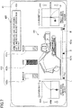
FIG. 2 is a block diagram illustrating a configuration of a basic system installed in the shovel ofFIG. 1 . -
FIG. 3A is a flowchart illustrating a process pertaining to an operation analysis. -
FIG. 3B is a flowchart illustrating another process pertaining to the operation analysis. -
FIG. 4 is a diagram illustrating a screen in the case of starting the operation analysis. -
FIG. 5 is a diagram illustrating another screen in the case of starting the operation analysis. -
FIG. 6 is a diagram illustrating a history screen. -
FIG. 7 is a diagram illustrating a first operation analysis screen. -
FIG. 8 is a diagram illustrating a second operation analysis screen. -
FIG. 9 is a diagram illustrating a third operation analysis screen. -
FIG. 1 is a side view of a shovel (an excavator) according to an embodiment of the present invention. An upper turningbody 3 is turnably mounted on a lower travelingbody 1 of the shovel via aturning mechanism 2. Aboom 4 is attached to the upper turningbody 3. Anarm 5 is attached to an end of theboom 4. Abucket 6 serving as an end attachment is attached to an end of thearm 5. A slope bucket, a dredging bucket, or the like may alternatively be used as an end attachment. - The
boom 4, thearm 5, and thebucket 6 form an excavation attachment as an example of an attachment, and are hydraulically driven by a boom cylinder 7, anarm cylinder 8, and abucket cylinder 9, respectively. A boom angle sensor S1 is attached to theboom 4. An arm angle sensor S2 is attached to thearm 5. A bucket angle sensor S3 is attached to thebucket 6. A bucket tilt mechanism may be provided on the excavation attachment. - The boom angle sensor S1 detects the rotation angle of the
boom 4. According to this embodiment, the boom angle sensor S1 is an acceleration sensor that detects the rotation angle of theboom 4 relative to the upper turningbody 3 by detecting an inclination to a horizontal plane. - The arm angle sensor S2 detects the rotation angle of the
arm 5. According to this embodiment, the arm angle sensor S2 is an acceleration sensor that detects the rotation angle of thearm 5 relative to theboom 4 by detecting an inclination to a horizontal plane. - The bucket angle sensor S3 detects the rotation angle of the
bucket 6. According to this embodiment, the bucket angle sensor S3 is an acceleration sensor that detects the rotation angle of thebucket 6 relative to thearm 5 by detecting an inclination to a horizontal plane. When the excavation attachment is provided with a bucket tilt mechanism, the bucket angle sensor S3 additionally detects the rotation angle of thebucket 6 about a tilt axis. - The boom angle sensor S1, the arm angle sensor S2, and the bucket angle sensor S3 may alternatively be potentiometers using a variable resistor, stroke sensors that detect the stroke amount of a corresponding hydraulic cylinder, or rotary encoders that detect a rotation angle about a connecting pin, or may be formed of a combination of an acceleration sensor and a gyro sensor.
- A
cabin 10 that is a cab is provided and power sources such as anengine 11 are mounted on the upper turningbody 3. Furthermore, a turning angular velocity sensor S4 and a camera S5 are attached to the upper turningbody 3. - The turning angular velocity sensor S4 is, for example, a gyro sensor, and detects the turning angular velocity of the upper turning
body 3. The turning angular velocity sensor S4 may alternatively be a resolver, a rotary encoder, or the like. - The camera S5 obtains an image of the surroundings of the shovel. According to this embodiment, the camera S5 is one or more cameras attached to the back of the upper turning
body 3. - A
controller 30, a display device, etc., are installed in thecabin 10. - The
controller 30 operates as a main control part to control the driving of the shovel. According to this embodiment, thecontroller 30 is composed of a processing unit including a CPU and an internal memory. The CPU executes a program stored in the internal memory to implement various functions of thecontroller 30. - The
display device 40 outputs various kinds of information in response to commands from thecontroller 30. According to this embodiment, thedisplay device 40 is an in-vehicle liquid crystal display directly connected to thecontroller 30. A touchscreen or the like may be attached. Thedisplay device 40 displays operation analysis information that is an analysis of an operator's operations on the shovel. Thedisplay device 40 may be a tablet, a cellular phone such as a smartphone, a PC, or the like. - Next, a basic system of the shovel is described with reference to
FIG. 2 . The basic system of the shovel mainly includes theengine 11, amain pump 14, apilot pump 15, acontrol valve 17, anoperating apparatus 26, thecontroller 30, and an engine control unit (ECU) 74. - The
engine 11 is the drive source of the shovel, and is, for example, a diesel engine that operates to maintain a predetermined rotational speed. The output shaft of theengine 11 is connected to the respective input shafts of themain pump 14 and thepilot pump 15. - The
main pump 14 is a hydraulic pump that supplies hydraulic oil to thecontrol valve 17 via ahydraulic oil line 16, and is a swash-plate variable displacement hydraulic pump, for example. Themain pump 14 can change a discharge flow rate, namely, pump output, by adjusting the stroke length of a piston by changing the angle (tilt angle) of a swash plate. The swash plate of themain pump 14 is controlled by aregulator 14a. Theregulator 14a includes an electromagnetic proportional valve (not depicted) that adjusts the pressure of hydraulic oil in a hydraulic circuit for controlling the tilt angle of the swash plate. Theregulator 14a changes the tilt angle of the swash plate in accordance with a change in a control current to the electromagnetic proportional valve. For example, when the control current increases, theregulator 14a increases the tilt angle of the swash plate to increase the discharge flow rate of themain pump 14. When the control current decreases, theregulator 14a decreases the tilt angle of the swash plate to decrease the discharge flow rate of themain pump 14. - The
pilot pump 15 is a hydraulic pump for supplying hydraulic oil to various hydraulic control apparatuses via apilot line 25, and is a fixed displacement hydraulic pump, for example. - The
control valve 17 is a set of hydraulic control valves. Thecontrol valve 17 selectively supplies hydraulic oil supplied from themain pump 14 through thehydraulic oil line 16 to one or more of hydraulic actuators in accordance with the direction of operation and the amount of operation of an operatinglever 26A, an operating lever 26B, and anoperating pedal 26C. The hydraulic actuators include the boom cylinder 7, thearm cylinder 8, thebucket cylinder 9, a travelinghydraulic motor 1A (left), a travelinghydraulic motor 1B (right), and a turninghydraulic motor 2A. - A
pressure sensor 51 is connected to the rod-side oil chamber of the boom cylinder 7. Thepressure sensor 51 detects the pressure of hydraulic oil in the rod-side oil chamber of the boom cylinder 7. Apressure sensor 52 is connected to the bottom-side oil chamber of thearm cylinder 8. Thepressure sensor 52 detects the pressure of hydraulic oil in the bottom-side oil chamber of thearm cylinder 8. Apressure sensor 53 is connected to the bottom-side oil chamber of thebucket cylinder 9. Thepressure sensor 53 detects the pressure of hydraulic oil in the bottom-side oil chamber of thebucket cylinder 9. - A
pressure sensor 54 and apressure sensor 55 are connected to the turninghydraulic motor 2A. Thepressure sensor 54 detects the pressure of hydraulic oil at a first port of the turninghydraulic motor 2A. Thepressure sensor 55 detects the pressure of hydraulic oil at a second port of the turninghydraulic motor 2A. - The
operating apparatus 26 is an apparatus that the operator uses to operate hydraulic actuators. Theoperating apparatus 26 generates a pilot pressure using hydraulic oil supplied from thepilot pump 15 via thepilot line 25, and causes the pilot pressure to act on a pilot port of a flow control valve corresponding to an individual hydraulic actuator through apilot line lever 26A, the operating lever 26B, or the operating pedal 26C corresponding to the individual hydraulic actuator. According to this embodiment, the operatinglever 26A is an operating lever placed on the right side of an operator seat, and is used to operate theboom 4 and thebucket 6. The operating lever 26B is an operating lever placed on the left side of the operator seat, and is used to operate thearm 5 and theupper turning body 3. - The
controller 30 controls the discharge flow rate of themain pump 14. For example, thecontroller 30 changes the above-described control current in accordance with a negative control pressure to control the discharge flow rate of themain pump 14 via theregulator 14a. - The
ECU 74 controls theengine 11. For example, theECU 74 controls the amount of fuel injection, etc., to control the rotational speed of theengine 11 based on a command from thecontroller 30. - An engine rotational
speed adjustment dial 75 is a dial for adjusting the rotational speed of theengine 11. According to this embodiment, the engine rotationalspeed adjustment dial 75 is provided in thecabin 10, and is configured to be able to switch the rotational speed of theengine 11 among four levels. For example, the engine rotationalspeed adjustment dial 75 is configured to be able to switch the rotational speed of theengine 11 among the four levels of SP mode, H mode, A mode, and idling mode.FIG. 2 illustrates that the SP mode is selected by the engine rotationalspeed adjustment dial 75. - The SP mode is a rotational speed mode selected when it is desired to prioritize workload, and uses the highest engine rotational speed. The H mode is a rotational speed mode selected when it is desired to satisfy both workload and fuel efficiency, and uses the second highest engine rotational speed. The A mode is a rotational speed mode selected when it is desired to operate the shovel with low noise while prioritizing fuel efficiency, and uses the third highest engine rotational speed. The idling mode is a rotational speed mode selected when it is desired to idle the engine, and uses the lowest engine rotational speed. The
engine 11 is controlled to maintain an engine rotational speed corresponding to a rotational speed mode selected by the engine rotationalspeed adjustment dial 75. The rotational speed of theengine 11 may also be switched among multiple levels whose number is other than four. - The
display device 40 is placed near the operator seat of thecabin 10 to assist the operator's operation, for example. Thedisplay device 40 includes animage display part 41 and aninput part 42. The operator can input information, commands, etc., to thecontroller 30, using theinput part 42 of thedisplay device 40. Furthermore, thedisplay device 40 can provide the operator with information by displaying the operation situation, control information, operation analysis information, etc., of the shovel on theimage display part 41. - According to this embodiment, the
display device 40 is fixed to a console inside the cab. In general, theboom 4 is placed on the right side when viewed from the operator seated on the operator seat. The operator often operates the shovel while looking at thearm 5 attached to the end of theboom 4 and thebucket 6 attached to the end of thearm 5. Therefore, the right front frame of thecabin 10 is a part that obstructs the operator's view. According to this embodiment, thedisplay device 40 is placed on this part that is an obstruction to the view from the beginning. Therefore, thedisplay device 40 itself is not a significant obstruction to the operator's view. Depending on the frame width, thedisplay device 40 may be so configured as to have theimage display part 41 in portrait orientation such that thedisplay device 40 is within the frame width in its entirety. - The
display device 40 includes, on theimage display part 41, an operation analysis start button serving as an operation analysis start input part for starting an operation analysis and storing a history of operation analyses. Furthermore, thedisplay device 40 includes, on theimage display part 41, an operation analysis check button serving as an operation analysis check input part for displaying the result of an operation analysis. - According to this embodiment, the
display device 40 is connected to thecontroller 30 via a communications network such as CAN or LIN. Thedisplay device 40 may alternatively be connected to thecontroller 30 via a dedicated line. - The
display device 40 includes aconversion part 40a to generate an image to be displayed on theimage display part 41. Theconversion part 40a generates an image to be displayed on theimage display part 41 based on the output of thecontroller 30. - The
conversion part 40a may be implemented not as a function of thedisplay device 40 but as a function of thecontroller 30. - The
display device 40 includes a switch panel serving as theinput part 42. The switch panel is a panel including various kinds of hardware switches. According to this embodiment, the switch panel includes alight switch 42a, awindshield wiper switch 42b, awindow washer switch 42c, ascreen switching button 42d, and acursor moving button 42e, which are hardware buttons. Thelight switch 42a is a switch for turning on and off lights attached to the exterior of thecabin 10. Thewindshield wiper switch 42b is a switch for moving and stopping a windshield wiper. Thewindow washer switch 42c is a switch for spraying windshield washer fluid. Thescreen switching button 42d is a button for switching screens displayed on theimage display part 41 of thedisplay device 40. Thecursor moving button 42e is a button for moving a selection area (cursor area) displayed on theimage display part 41 of thedisplay device 40 to select and determine various setting items. - The
display device 40 is supplied with electric power from arechargeable battery 70 to operate. Therechargeable battery 70 is charged with electric power generated in analternator 11a (generator) of theengine 11. The electric power of therechargeable battery 70 is also supplied toelectrical equipment 72, etc., of the shovel besides thecontroller 30 and thedisplay device 40. Furthermore, astarter 11b of theengine 11 is driven with electric power from therechargeable battery 70 to start theengine 11. - The
engine 11 is controlled by theECU 74. TheECU 74 transmits various data indicating the condition of theengine 11 to thecontroller 30. Examples of the various data include data indicating coolant water temperature (a physical quantity) detected with awater temperature sensor 11c. - Various data are fed to the
controller 30 as follows. Theregulator 14a of themain pump 14 transmits data indicating the tilt angle of the swash plate to thecontroller 30. Adischarge pressure sensor 14b transmits data indicating the discharge pressure of themain pump 14 to thecontroller 30. These data representing physical quantities are stored in aprimary storage part 30a. Anoil temperature sensor 14c is provided in a conduit between themain pump 14 and a tank storing hydraulic oil that themain pump 14 draws in. Theoil temperature sensor 14c transmits data representing the temperature of hydraulic oil flowing through the conduit to thecontroller 30. - A pilot pressure transmitted to the
control valve 17 through thepilot line lever 26A, the operating lever 26B, or the operating pedal 26C is operated is detected byoil pressure sensor oil pressure sensors controller 30. Thepressure sensors 51 through 55 transmit their respective pressure values to thecontroller 30. - The engine rotational
speed adjustment dial 75 transmits data indicating the setting of the engine rotational speed to thecontroller 30. - The
controller 30 stores data in theprimary storage part 30a. Theprimary storage part 30a is a device for storing various kinds of information. According to this embodiment, theprimary storage part 30a is a non-volatile storage medium such as a semiconductor memory. Alternatively, however, theprimary storage part 30a may be a volatile storage medium. - When accumulated for a predetermined capacity, data stored in the
primary storage part 30a are overwritten by new data. According to this embodiment, for example, when a currently detected pressure value exceeds a threshold, thecontroller 30 transfers past detection values (hereinafter also referred to as operation history) stored in theprimary storage part 30a to amain storage part 31. Themain storage part 31 is a non-volatile storage medium. - The
main storage part 31 or theprimary storage part 30a may store reference data related to shovel operations, which thecontroller 30 uses in an operation analysis. The reference data are data related to shovel operations, and are data related to ideal operational details represented by the timing of operation, the direction of operation, the amount of operation, etc., of an operating lever, for example. - The
controller 30 performs an operation analysis based on pilot pressures from theoil pressure sensors pressure sensors 51 through 55, and a discharge pressure from thedischarge pressure sensor 14b, displays the result of the operation analysis on theimage display part 41 of thedisplay device 40. - Furthermore, the
controller 30 compares the data of the operation analysis with the reference data stored in themain storage part 31 or theprimary storage part 30a to calculate an example of improvement, and displays the example of improvement on theimage display part 41 of thedisplay device 40 as the result of the operation analysis. The example of improvement is data related to shovel operations for reducing a difference between the reference data and the data of the operation analysis, and is stored in themain storage part 31. The example of improvement is represented by, for example, the timing of operation, the direction of operation, or the amount of operation of an operating lever or a combination thereof. - Next, a flow of a process related to an operation analysis is specifically described with reference to
FIGS. 3A and3B .FIG. 3A is a flowchart illustrating a process of starting an operation analysis.FIG. 3B is a flowchart illustrating a process of displaying the result of an operation analysis on theimage display part 41. - As illustrated in
FIG. 3A , in the case of desiring an operation analysis, an operator presses an operation analysis start button displayed on theimage display part 41 to input an operation analysis start (ST1). Then, the operator operates the shovel. - The
controller 30 then obtains pressure values from oil pressure sensors. According to this embodiment, thecontroller 30 obtains pilot pressures from theoil pressure sensors pressure sensors 51 through 55, a discharge pressure from thedischarge pressure sensor 14b, etc. Thecontroller 30 compares the obtained pressure values with the reference data stored in theprimary storage part 30a or themain storage part 31 to determine whether there is a pressure value exceeding a threshold (ST2). - If none of the obtained pressure values exceeds a threshold (NO at ST2), the
controller 30 repeats the determination of ST2. - If there is a pressure value exceeding a threshold (YES at ST2), the
controller 30 stores an operation situation before and after a point of time at which the threshold is exceeded in themain storage part 31 as an operation analysis history (ST3). A period for which the operation situation is stored is, for example, five seconds before and after the point of time at which the threshold is exceeded. - Here, an example of an operation
analysis start button 50S displayed on theimage display part 41 is described with reference toFIGS. 4 and5 .FIG. 4 is a diagram illustrating a screen in the case of starting an operation analysis.FIG. 5 is a diagram illustrating another screen in the case of starting an operation analysis. - The operation
analysis start button 50S is displayed on amenu screen 400. Themenu screen 400 is a screen displayed at the start of a shovel operation. - Accordingly, the operator can input starting an operation analysis of the operator's shovel operation. When the operator presses the operation
analysis start button 50S on themenu screen 400, the operationanalysis start button 50S switches to an operationanalysis check button 50C. Alternatively, however, the operationanalysis start button 50S and the operationanalysis check button 50C may both be displayed on themenu screen 400. - Various setting items are displayed on the
menu screen 400. According to this embodiment, a cursor area CS serving as a selection area movable over the setting items is displayed on theimage display part 41. The operator can switch languages, adjust screen brightness, etc., by moving the cursor area CS. In addition, the operator can perform switching to a maintenance information screen, a time adjustment screen, etc. The operator can move the cursor area CS using thecursor moving button 42e illustrated inFIG. 2 . When theimage display part 41 is a touchscreen, the operator may move the cursor area CS by a touch operation. - The operation
analysis start button 50S may also be displayed on amain screen 410 illustrated inFIG. 5 . Themain screen 410 is a screen displayed during a shovel operation. The operator switches themenu screen 400 illustrated inFIG. 4 and themain screen 410 illustrated inFIG. 5 , using thescreen switching button 42d illustrated inFIG. 2 . - As illustrated in
FIG. 5 , themain screen 410 includes a date andtime display area 41a, a travelingmode display area 41b, an endattachment display area 41c, an engine controlstatus display area 41e, an engine operating time display area 41f, a coolant watertemperature display area 41g, a remaining fuelamount display area 41h, a rotational speedmode display area 41i, a hydraulic oiltemperature display area 41k, a cameraimage display area 41m, anorientation indicator icon 41x, and the operationanalysis start button 50S. The travelingmode display area 41b, the endattachment display area 41c, the engine controlstatus display area 41e, the rotational speedmode display area 41i, and theorientation indicator icon 41x are specific examples of the settings display part of the shovel. The engine operating time display area 41f, the coolant watertemperature display area 41g, the remaining fuelamount display area 41h, and the hydraulic oiltemperature display area 41k are specific examples of the operating condition display part of the shovel. - When the operator presses the operation
analysis start button 50S on themain screen 410, the operationanalysis start button 50S switches to the operationanalysis check button 50C. Alternatively, however, the operationanalysis start button 50S and the operationanalysis check button 50C may both be displayed on themain screen 410. - The date and
time display area 41a displays a current date and time. The travelingmode display area 41b displays a current traveling mode. The traveling mode represents the setting of traveling hydraulic motors. Specifically, the traveling mode includes a low-speed mode and a high-speed mode. The low-speed mode is represented by, for example, a "turtle"-shaped mark, and the high-speed mode is represented by, for example, a "rabbit"-shaped mark. - The end
attachment display area 41c displays an image that represents the type of a currently attached end attachment. InFIG. 5 , a bucket-shaped mark is displayed. The engine controlstatus display area 41e displays the control status of theengine 11. InFIG. 5 , the operator can recognize that "automatic deceleration and automatic stop mode" is selected as the control status of theengine 11. Other control statuses of theengine 11 include "automatic deceleration mode," "automatic stop mode," and "manual deceleration mode." - The engine operating time display area 41f displays the cumulative operating time of the
engine 11. InFIG. 5 , a value using a unit "hr (hour)" is displayed. The coolant watertemperature display area 41g displays the current temperature condition of engine coolant water. The remaining fuelamount display area 41h displays the status of the remaining amount of fuel stored in a fuel tank. - The rotational speed
mode display area 41i displays a current rotational speed mode. The rotational speed mode includes, for example, the four modes of SP mode, H mode, A mode, and idling mode. InFIG. 5 , a symbol "SP" representing SP mode is displayed. The hydraulic oiltemperature display area 41k displays the temperature condition of hydraulic oil in a hydraulic oil tank. - The camera
image display area 41m displays a camera image. According to this embodiment, the shovel includes the camera S5 (seeFIG. 1 ) for capturing images of the outside of the operator's view. The camera S5 transmits a captured camera image to theconversion part 40a of thedisplay device 40. As a result, the operator can visually recognize the camera image captured by the camera S5 on themain screen 410 of thedisplay device 40. - The
orientation indicator icon 41x represents the relative relationship between the orientation of a camera that has captured a camera image that is displayed in the cameraimage display area 41m and the orientation of the shovel (the attachment of the upper turning body 3). - The operation
analysis start button 50S is desirably displayed between the engine operating time display area 41f and the coolant watertemperature display area 41g on themain screen 410, but may alternatively be displayed in other areas on themain screen 410. - As illustrated in
FIG. 5 , the operationanalysis start button 50S is displayed on themain screen 410 that is displayed during an operation of the shovel. Therefore, even during a shovel operation, the operator can start an operation analysis of the operator's shovel operation by pressing the operationanalysis start button 50S. - Next, a process of displaying the result of an operation analysis on the
image display part 41 of thedisplay device 40 is specifically described with reference toFIG. 3B . - As illustrated in
FIG. 3B , when desiring to check the result of an operation analysis, the operator presses the operationanalysis check button 50C displayed on the image display part 41 (ST21). When the operator presses the operationanalysis start button 50S at ST21, thecontroller 30 starts an operation analysis. When the operation analysis ends, thedisplay device 40 switches the operationanalysis start button 50S to the operationanalysis check button 50C on themenu screen 400 or themain screen 410. Accordingly, the operationanalysis check button 50C is displayed at the position of the operationanalysis start button 50S on themenu screen 400 ofFIG. 4 or themain screen 410 ofFIG. 5 . The operator can view operation analysis information on the operator's shovel operation by pressing the operationanalysis check button 50C when performing no shovel operation such as while waiting for a dump truck. - In response to the pressing of the operation
analysis check button 50C by the operator at ST21, thedisplay device 40 displays ahistory screen 420 illustrated inFIG. 6 on the image display part 41 (ST22). A list of operation analysis histories that thecontroller 30 stores in themain storage part 31 at ST3 ofFIG. 3A is displayed on thehistory screen 420. - The
history screen 420 illustrated inFIG. 6 can display multiple operation analysis histories such asoperation analysis histories 421 through 423. For example, in theoperation analysis history 421 as depicted, date andtime data 421a of when a threshold was exceeded and ananalysis type 421b are displayed. The same information is displayed with respect to the otheroperation analysis histories analysis type 421b. The efficiency analysis is displayed when a pressure value exceeding a threshold is detected by thecontroller 30. The stability analysis is displayed when an acceleration exceeding a threshold is detected by thecontroller 30. - When the operator selects a desired operation analysis history from the list of operation analysis histories of the history screen 420 (ST23), the
display device 40 displays a firstoperation analysis screen 430 illustrated inFIG. 7 on the image display part 41 (ST24).FIG. 7 illustrates a screen that is displayed when the operator selects theoperation analysis history 421 on thehistory screen 420. Theoperation analysis history 421 relates to an excavating time operation. - The first
operation analysis screen 430 includes a shovelmotion display area 431, a cylinderpressure display area 432, a right-side operatinglever display area 433, a left-side operatinglever display area 434, and amessage display area 435. - The shovel
motion display area 431 displays the result of an operation analysis performed by thecontroller 30, using a model of the shovel. According to this embodiment, the motion of the shovel based on an operation history of five seconds before and after a point of time at which a predetermined detection value exceeds a predetermined threshold (ten seconds in total) is reproduced in animation. Data on operation histories are stored in themain storage part 31. A model of the shovel is, for example, a computer graphic model (CG model). - The shovel
motion display area 431 includes amotion display part 431a that reproduces an operation history in animation with a CG model of the shovel and a seekbar 431b that indicates the position of reproduction of themotion display part 431a. The seekbar 431b is a horizontally extending bar whose length corresponds to the reproduction time of animation. Accordingly, in the seekbar 431b ofFIG. 7 , a point of time at which a detection value exceeds a threshold is indicated by a central position S, a point of time five seconds before a point of time at which a detection value exceeds a threshold (-5s) is indicated by a left-end position L, and a point of time five seconds after a point of time at which a detection value exceeds a threshold (+5s) is indicated by a right-end position R. - The display areas illustrated in
FIG. 7 show a state at a point of time five seconds after a point of time at which a detection value exceeds a threshold. - The cylinder
pressure display area 432 displays the result of an operation analysis performed by thecontroller 30 with the bar graph representation of the respective cylinder pressures of thebucket cylinder 9, thearm cylinder 8, and the boom cylinder 7 that are linked to the movement of the attachment. The bar graph representation of cylinder pressures displayed in the cylinderpressure display area 432 is a graphic representation of cylinder pressures, and is linked to the animated motion of the shovel displayed in themotion display part 431a. The graphic representation of cylinder pressures may alternatively be a round analog meter representation, a seven-segment number representation, or the like. - The cylinder
pressure display area 432 includes a bucketpressure display part 432a that displays the cylinder pressure of thebucket cylinder 9, an armpressure display part 432b that displays the cylinder pressure of thearm cylinder 8, and a boompressure display part 432c that displays the cylinder pressure of the boom cylinder 7. - In
FIG. 7 , the bucketpressure display part 432a displays the bottom-side cylinder pressure of thebucket cylinder 9. The armpressure display part 432b displays the bottom-side cylinder pressure of thearm cylinder 8. The boompressure display part 432c displays the rod-side cylinder pressure of the boom cylinder 7. - The cylinder
pressure display area 432 illustrated inFIG. 7 shows that the pressure of thearm 5 is higher than the pressure of thebucket 6. This means that it is highly likely that the operator is forcibly excavating with thearm 5. The armpressure display part 432b illustrated inFIG. 7 is displayed in, for example, red. The armpressure display part 432b may be displayed in red when the pressure of thearm cylinder 8 becomes higher than or equal to a threshold. The same is the case with the bucketpressure display part 432a and the boompressure display part 432c. The pressure value of the armpressure display part 432b illustrated inFIG. 7 shows the largest pressure during the display period (ten seconds). - The right-side operating
lever display area 433 displays the operation track of the operatinglever 26A placed on the right side of the operator seat in a plan view. InFIG. 7 , the right-side operatinglever display area 433 is a square display area, where a central position P indicates the reference position (neutral position) of the operatinglever 26A. The right-side operatinglever display area 433 corresponds to the operation of the operatinglever 26A, and a forward (upward) direction corresponds to the operation of lowering theboom 4 and a backward (downward) direction corresponds to the operation of raising theboom 4. Furthermore, a leftward direction corresponds to the operation of closing thebucket 6, and a rightward direction corresponds to the operation of opening thebucket 6. The right-side operatinglever display area 433 displays the operation track of the operatinglever 26A in conjunction with the animated motion of the shovel displayed in themotion display part 431a. - The left-side operating
lever display area 434 displays the operation track of the operating lever 26B placed on the left side of the operator seat in a plan view. InFIG. 7 , the left-side operatinglever display area 434 is a square display area, where a central position P indicates the reference position (neutral position) of the operating lever 26B. The left-side operatinglever display area 434 corresponds to the operation of the operating lever 26B, and a forward (upward) direction corresponds to the operation of opening thearm 5 and a backward (downward) direction corresponds to the operation of closing thearm 5. Furthermore, a leftward direction corresponds to a leftward turning operation, and a rightward direction corresponds to a rightward turning operation. The left-side operatinglever display area 434 displays the operation track of the operating lever 26B in conjunction with the animated motion of the shovel displayed in themotion display part 431a. - The
message display area 435 displays the result of an operation analysis and an improvement method with a message. Accordingly, the operator can objectively recognize how the operator actually operates levers by checking the right-side operatinglever display area 433, the left-side operatinglever display area 434, and the cylinderpressure display area 432. - For example, from the display of the first
operation analysis screen 430 illustrated inFIG. 7 , the operator who is a target of analysis understands that the following operations have been performed. Specifically, from the display of the left-side operatinglever display area 434, the operator understands that the operating lever 26B is operated in a closing direction in one attempt when operating thearm 5 in a closing direction. Furthermore, from the display of the right-side operatinglever display area 433, the operator understands that theboom 4 was gradually operated in a rising direction with the closing operation of thearm 5, and understands that thebucket 6 was operated in a closing direction at the last stage of excavation. - It is understood from the display of the cylinder
pressure display area 432, however, that these operations are operations that apply a high pressure only to thearm cylinder 8. Accordingly, in themessage display area 435 illustrated inFIG. 7 , a message that reads "ARM PRESSURE HAS INCREASED. LET'S INCREASE BUCKET OPERATION AMOUNT" is displayed. - By checking the results of operation analyses displayed on the first
operation analysis screen 430, the operator can objectively recognize the current state of the operator's shovel operations as described above, and can also take a hint for the improvement of the operational ability. - In this manner, the
image display part 41 can display the result of an operation analysis. The form of display of the result of an operation analysis displayed on theimage display part 41, however, is not limited to the firstoperation analysis screen 430 illustrated inFIG. 7 . For example, thedisplay device 40 may display the firstoperation analysis screen 430 illustrated inFIG. 7 on theimage display part 41 and thereafter display a secondoperation analysis screen 440 illustrated inFIG. 8 on theimage display part 41. - The second
operation analysis screen 440 displays an improvement on the operator's operation history as the result of an operation analysis. Accordingly, by checking the secondoperation analysis screen 440, the operator can understand what specific improvement to make to improve the operational ability. - The second
operation analysis screen 440 includes a shovelmotion display area 441, a cylinderpressure display area 442, a right-side operatinglever display area 443, a left-side operatinglever display area 444, and amessage display area 445. The secondoperation analysis screen 440 has substantially the same display area and is in substantially the same form of display as the firstoperation analysis screen 430. Therefore, a description of a common part is omitted, and a description is focused on differences. - The shovel
motion display area 441 displays an improvement on the operator's operation history in animation with a CG model of the shovel. According to this embodiment, an improvement on an operation history of five seconds before and after a point of time at which a predetermined detection value exceeds a predetermined threshold (ten seconds in total) is reproduced in animation. - The cylinder
pressure display area 442 displays an improvement on the operator's operation history with the bar graph representation of the respective cylinder pressures of thebucket cylinder 9, thearm cylinder 8, and the boom cylinder 7 that are linked to the movement of the attachment. The bar graph representation of cylinder pressures displayed in the cylinderpressure display area 442 is linked to the animated motion of the shovel displayed in amotion display part 441a. - Furthermore, the cylinder
pressure display area 442 displays a level line L1 indicating a maximum cylinder pressure X calculated by thecontroller 30 in an operation analysis and a level line L2 indicating a target cylinder pressure X' serving as an improvement. InFIG. 8 , an armpressure display part 442b displays the inside of an area between the level line L1 and the level line L2 in red, and displays an arrow icon Y1 giving an instruction to decrease the cylinder pressure to the level line L2. A bucketpressure display part 442a displays an arrow icon Y2 giving an instruction to increase the cylinder pressure to the level line L2. - The level lines L1 and L2 illustrated in
FIG. 8 are shared by the bucketpressure display part 442a, the armpressure display part 442b, and a boompressure display part 442c. The level lines L1 and L2, however, may alternatively be displayed in each of the bucketpressure display part 442a, the armpressure display part 442b, and the boompressure display part 442c independently. - The right-side operating
lever display area 443 displays the operation track of the operatinglever 26A with respect to an improvement in a plan view. The right-side operatinglever display area 443 corresponds to the operation of the operatinglever 26A with respect an improvement. Specifically, forward and backward (upward and downward) directions correspond to the lowering and raising of theboom 4 and leftward and rightward directions correspond to the closing and opening of thebucket 6. The right-side operatinglever display area 443 displays the operation track of the operatinglever 26A with respect to an improvement in conjunction with the animated motion of the shovel displayed in themotion display part 441a. - The left-side operating
lever display area 444 displays the operation track of the operating lever 26B with respect to an improvement in a plan view. The left-side operatinglever display area 444 corresponds to the operation of the operating lever 26B with respect an improvement. Specifically, forward and backward (upward and downward) directions correspond to the opening and closing of thearm 5, a leftward direction corresponds to leftward turning, and a rightward direction corresponds to rightward turning. The left-side operatinglever display area 444 displays the operation track of the operating lever 26B with respect to an improvement in conjunction with the animated motion of the shovel displayed in themotion display part 441a. - The right-side operating
lever display area 443 illustrated inFIG. 8 displays an operation track K1 of the operatinglever 26A according to an operation analysis performed by thecontroller 30 and an operation track K2 of the operatinglever 26A showing an improvement based on the result of the operation analysis. - The operation track K1 shows an operation track based on an operation analysis of the operating
lever 26A during a period from Time T1 to Time T4. The operation track K2 shows an operation track based on an improvement of the operatinglever 26A during a period from Time T1' to Time T4'. Time T1 through Time T4 correspond to Time T1' through Time T4', respectively. - The operation track K2 illustrated in
FIG. 8 gives an instruction to increase the amount of operation of thebucket 6 between Time T3' and Time T4'. - The
message display area 445 displays the result of an operation analysis and an improvement method with a message. In themessage display area 445 illustrated inFIG. 8 , a message that reads "ARM PRESSURE HAS INCREASED. LET'S INCREASE BUCKET OPERATION AMOUNT" is displayed. - By checking an improvement displayed on the second
operation analysis screen 440, the operator can intuitively understand what specific lever operation can improve the operational ability. - By looking at the left-side operating
lever display area 444, the operator understands that the operating lever 26B is operated in a closing direction in one attempt when operating thearm 5 in a closing direction. Furthermore, by looking at the operation track K1 of the right-side operatinglever display area 443, the operator understands that theboom 4 was gradually operated in a rising direction with the closing operation of thearm 5, and understands that thebucket 6 was operated in a closing direction at the last stage of excavation. - Furthermore, by paying attention to the operation track K2 of the right-side operating
lever display area 443, the operator understands, at a glance, how to operate the operatinglever 26A to be able to improve shovel operations. The operation track K2 illustrated inFIG. 8 indicates no need to improve the operation between Time T1' and Time T3', while indicating the necessity of increasing the amount of operation of thebucket 6 by further tilting the operatinglever 26A leftward between Time T3' and Time T4'. Therefore, the operator can understand the necessity of the operation of tilting the operatinglever 26A leftward between Time T3' and Time T4'. - According to the above-described embodiment, the
display device 40 displays the firstoperation analysis screen 430 and the secondoperation analysis screen 440 as separate screens. Thedisplay device 40, however, may alternatively display the firstoperation analysis screen 430 and the secondoperation analysis screen 440 in the same screen. As another alternative, thedisplay device 40 may display at least one of the firstoperation analysis screen 430 and the secondoperation analysis screen 440 and at least one of a camera image, the settings display part, and the operating condition display part on separate screens or simultaneously on the same screen. -
FIG. 9 illustrates a thirdoperation analysis screen 450 including a first operation analysis screen and a second operation analysis screen. The thirdoperation analysis screen 450 illustrated inFIG. 9 includes an operationhistory display area 451 in which the firstoperation analysis screen 430 illustrated inFIG. 7 is displayed and animprovement display area 452 in which the secondoperation analysis screen 440 illustrated inFIG. 8 is displayed. A reproduction time with respect to the seekbar 431b of the operationhistory display area 451 is equal to a reproduction time with respect to a seekbar 441b of theimprovement display area 452. - The third
operation analysis screen 450 has the operationhistory display area 451 and theimprovement display area 452 vertically arranged. Therefore, it is possible to highlight a difference between an actual operation history and an improvement, and it is possible to suggest or teach a specific improvement with respect to shovel operations to the operator in an easily understandable manner. - Furthermore, the motion of the
bucket 6 is quicker in an improvement taught in theimprovement display area 452 than in the actual operation history of the operator displayed in the operationhistory display area 451, thus contributing to smooth excavation work. - A preferred embodiment of the present invention is described in detail above. The present invention, however, is not limited to the above-described embodiment. Variations and replacements may be applied to the above-described embodiment without departing from the scope of the present invention as defined in the appended claims.
- 1 ... lower traveling
body 2 ...turning mechanism 3 ...upper turning body 4 ...boom 5 ...arm 6 ... bucket 7 ...boom cylinder 8 ...arm cylinder 9 ...bucket cylinder 10 ...cabin 11 ...engine 14 ...main pump 15 ...pilot pump 16 ...hydraulic line 17 ...control valve 26 ... operatingapparatus 30 ...controller 30a ...primary storage part 31 ...main storage part 40 ...display device 41 ...image display part 50S ... operationanalysis start button 50C ... operation analysis check button 51-55 ...pressure sensor 400 ...menu screen 410 ...main screen 420 ...history screen 430 ... firstoperation analysis screen 431 ... shovelmotion display area 432 ... cylinderpressure display area 433 ... right-side operatinglever display area 434 ... left-side operatinglever display area 435 ...message display area 440 ... secondoperating analysis screen 441 ... shovelmotion display area 442 ... cylinderpressure display area 443 ... right-side operatinglever display area 444 ... left-side operatinglever display area 445 ...message display area 450 ... thirdoperating analysis screen 451 ... operationhistory display area 452 ... improvement display area S1 ... boom angle sensor S2 ... arm angle sensor S3 ... bucket angle sensor S4 ... turning angular velocity sensor S5 ... camera
Claims (10)
- A display device (40) for a shovel, the shovel including an attachment, the attachment including a boom (4), an arm (5), and an end attachment, characterised by the display device (40) comprising:an operation analysis start input part for starting an operation analysis of the shovel and storing a history of the operation analysis; andan operation analysis check input part for displaying a result of the operation analysis and an operation history of the shovel on a same screen (41).
- The display device (40) for the shovel as claimed in claim 1, wherein the operation history of the shovel is displayed using a model of the shovel.
- The display device (40) for the shovel as claimed in claim 1, wherein the operation history of the shovel is displayed using a cylinder pressure linked to a movement of the attachment.
- The display device (40) for the shovel as claimed in claim 1, wherein the operation history of the shovel is displayed using a track of an operating lever for operating the attachment.
- The display device (40) for the shovel as claimed in claim 1, wherein an improvement on the operation history of the shovel is displayed using a model of the shovel.
- The display device (40) for the shovel as claimed in claim 1, wherein an improvement on the operation history of the shovel is displayed using a cylinder pressure linked to a movement of the attachment.
- The display device (40) for the shovel as claimed in claim 1, wherein an improvement on the operation history of the shovel is displayed using a track of an operating lever for operating the attachment.
- The display device (40) for the shovel as claimed in claim 1, wherein the result of the operation analysis and a camera image are simultaneously displayed.
- The display device (40) for the shovel as claimed in claim 1, wherein the result of the operation analysis and a part for displaying settings of the shovel are simultaneously displayed.
- The display device (40) for the shovel as claimed in claim 1, wherein the result of the operation analysis and a part for displaying an operating condition of the shovel are simultaneously displayed.
Applications Claiming Priority (2)
| Application Number | Priority Date | Filing Date | Title |
|---|---|---|---|
| JP2016085324 | 2016-04-21 | ||
| PCT/JP2017/015971 WO2017183707A1 (en) | 2016-04-21 | 2017-04-21 | Display device for shovel |
Publications (3)
| Publication Number | Publication Date |
|---|---|
| EP3447198A1 EP3447198A1 (en) | 2019-02-27 |
| EP3447198A4 EP3447198A4 (en) | 2019-04-03 |
| EP3447198B1 true EP3447198B1 (en) | 2020-09-02 |
Family
ID=60116122
Family Applications (1)
| Application Number | Title | Priority Date | Filing Date |
|---|---|---|---|
| EP17786044.2A Active EP3447198B1 (en) | 2016-04-21 | 2017-04-21 | Display device for a shovel |
Country Status (6)
| Country | Link |
|---|---|
| US (1) | US11525244B2 (en) |
| EP (1) | EP3447198B1 (en) |
| JP (1) | JP6776343B2 (en) |
| KR (1) | KR102333772B1 (en) |
| CN (1) | CN109072588B (en) |
| WO (1) | WO2017183707A1 (en) |
Families Citing this family (15)
| Publication number | Priority date | Publication date | Assignee | Title |
|---|---|---|---|---|
| JP6480830B2 (en) * | 2015-08-24 | 2019-03-13 | 株式会社小松製作所 | Wheel loader control system, control method therefor, and wheel loader control method |
| EP3543402A1 (en) * | 2018-03-19 | 2019-09-25 | Joseph Vögele AG | Construction machine for constructing or processing of a street |
| JP7286287B2 (en) * | 2018-09-14 | 2023-06-05 | 株式会社小松製作所 | Work machine display system and its control method |
| JP7197314B2 (en) * | 2018-09-14 | 2022-12-27 | 株式会社小松製作所 | Work machine display system and its control method |
| JP7206956B2 (en) | 2019-01-28 | 2023-01-18 | コベルコ建機株式会社 | working machine |
| JP7365122B2 (en) * | 2019-02-01 | 2023-10-19 | 株式会社小松製作所 | Image processing system and image processing method |
| JP7088866B2 (en) * | 2019-03-18 | 2022-06-21 | 日立建機株式会社 | Construction machinery |
| JP7287045B2 (en) * | 2019-03-26 | 2023-06-06 | コベルコ建機株式会社 | remote control system |
| US20220195704A1 (en) * | 2019-04-04 | 2022-06-23 | Komatsu Ltd. | System including work machine, computer implemented method, method for producing trained posture estimation model, and training data |
| JP7215959B2 (en) * | 2019-04-26 | 2023-01-31 | 株式会社小松製作所 | Regeneration device, analysis support system and regeneration method |
| JP7388954B2 (en) * | 2020-03-11 | 2023-11-29 | 株式会社小松製作所 | Operation guide device |
| JP2021143498A (en) * | 2020-03-11 | 2021-09-24 | 株式会社小松製作所 | Operation system |
| CN111879525A (en) * | 2020-07-30 | 2020-11-03 | 雷沃工程机械集团有限公司 | Test evaluation system and method for quantifying overall stability of excavator |
| US20230183942A1 (en) * | 2021-11-17 | 2023-06-15 | Yanmar Holdings Co., Ltd. | Work Machine Control Method, Work Machine Control Program, Work Machine Control System, And Work Machine |
| EP4350079A1 (en) * | 2022-10-06 | 2024-04-10 | BAUER Maschinen GmbH | Civil engineering machine and method for operating a civil engineering machine |
Family Cites Families (27)
| Publication number | Priority date | Publication date | Assignee | Title |
|---|---|---|---|---|
| JPS57119850U (en) | 1981-01-14 | 1982-07-26 | ||
| JPS5996339A (en) * | 1982-11-22 | 1984-06-02 | Komatsu Ltd | Detection of actual operation condition of construction machine |
| WO2001073217A1 (en) * | 2000-03-31 | 2001-10-04 | Hitachi Construction Machinery Co., Ltd. | Method for managing construction machine and arithmetic processing apparatus |
| JP2002317472A (en) * | 2001-04-23 | 2002-10-31 | Komatsu Ltd | Monitor device for working vehicle |
| JP4506286B2 (en) * | 2003-08-19 | 2010-07-21 | 株式会社小松製作所 | Construction machinery |
| JP4629377B2 (en) | 2003-09-02 | 2011-02-09 | 株式会社小松製作所 | Construction machinery |
| JP4173121B2 (en) * | 2003-09-02 | 2008-10-29 | 株式会社小松製作所 | Construction machine operation system |
| JP3902168B2 (en) * | 2003-09-04 | 2007-04-04 | 日立建機株式会社 | Diagnostic information display system for construction machinery |
| CN100498861C (en) * | 2003-10-31 | 2009-06-10 | 株式会社小松制作所 | Working machine management system |
| JP4746000B2 (en) | 2007-03-27 | 2011-08-10 | 株式会社小松製作所 | Fuel saving driving support method and fuel saving driving support system for construction machinery |
| JP5009827B2 (en) * | 2008-01-31 | 2012-08-22 | 株式会社小松製作所 | Work machine |
| JP5133755B2 (en) * | 2008-03-28 | 2013-01-30 | 株式会社小松製作所 | Construction machine operation evaluation system and operation evaluation method |
| JP4917574B2 (en) * | 2008-06-24 | 2012-04-18 | 住友建機株式会社 | Drive control device having learning function and construction machine including the same |
| JP5233751B2 (en) * | 2009-03-03 | 2013-07-10 | コベルコ建機株式会社 | Work machine |
| JP2011038346A (en) | 2009-08-13 | 2011-02-24 | Hitachi Constr Mach Co Ltd | Construction machine |
| US8437920B2 (en) * | 2010-06-04 | 2013-05-07 | Caterpillar Global Mining Llc | Dual monitor information display system and method for an excavator |
| JP5586568B2 (en) * | 2011-11-15 | 2014-09-10 | 株式会社小松製作所 | Construction machine information display device, construction machine information display method, and construction machine information display computer program |
| US9650762B2 (en) * | 2012-01-24 | 2017-05-16 | Harnischfeger Technologies, Inc. | System and method for monitoring mining machine efficiency |
| KR101928576B1 (en) * | 2012-01-30 | 2018-12-12 | 두산인프라코어 주식회사 | Information servicing system for fuel efficiency of construction machinery |
| JP5529949B2 (en) * | 2012-11-20 | 2014-06-25 | 株式会社小松製作所 | Work machine and work management system |
| WO2014136956A1 (en) * | 2013-03-08 | 2014-09-12 | 日立建機株式会社 | Management server for work machine and management method for work machine |
| JP2015040422A (en) * | 2013-08-22 | 2015-03-02 | 日立建機株式会社 | Display device of construction machine |
| JP6200801B2 (en) | 2013-12-24 | 2017-09-20 | 株式会社Kcm | Work machine |
| JP2015132090A (en) * | 2014-01-10 | 2015-07-23 | キャタピラー エス エー アール エル | Construction machinery |
| JP6333598B2 (en) * | 2014-03-27 | 2018-05-30 | 住友重機械工業株式会社 | Excavator support device and excavator |
| JP6466080B2 (en) * | 2014-04-25 | 2019-02-06 | 住友建機株式会社 | Construction machinery |
| JPWO2016157462A1 (en) * | 2015-03-31 | 2018-01-25 | 株式会社小松製作所 | Work machine periphery monitoring device |
-
2017
- 2017-04-21 EP EP17786044.2A patent/EP3447198B1/en active Active
- 2017-04-21 KR KR1020187030446A patent/KR102333772B1/en active IP Right Grant
- 2017-04-21 WO PCT/JP2017/015971 patent/WO2017183707A1/en active Application Filing
- 2017-04-21 CN CN201780024932.1A patent/CN109072588B/en active Active
- 2017-04-21 JP JP2018513221A patent/JP6776343B2/en active Active
-
2018
- 2018-10-18 US US16/163,800 patent/US11525244B2/en active Active
Non-Patent Citations (1)
| Title |
|---|
| None * |
Also Published As
| Publication number | Publication date |
|---|---|
| EP3447198A1 (en) | 2019-02-27 |
| CN109072588A (en) | 2018-12-21 |
| EP3447198A4 (en) | 2019-04-03 |
| WO2017183707A1 (en) | 2017-10-26 |
| KR102333772B1 (en) | 2021-11-30 |
| KR20180136959A (en) | 2018-12-26 |
| US20190048560A1 (en) | 2019-02-14 |
| US11525244B2 (en) | 2022-12-13 |
| JP6776343B2 (en) | 2020-10-28 |
| CN109072588B (en) | 2021-10-08 |
| JPWO2017183707A1 (en) | 2019-02-28 |
Similar Documents
| Publication | Publication Date | Title |
|---|---|---|
| EP3447198B1 (en) | Display device for a shovel | |
| CN107542122B (en) | Display device of excavator | |
| JP6965160B2 (en) | Excavator | |
| EP3276089B1 (en) | Shovel | |
| US11001992B2 (en) | Shovel, display method, and mobile terminal | |
| CN107849835B (en) | Construction machine and control method for construction machine | |
| EP3604695B1 (en) | Shovel with display device and image display method in shovel | |
| EP3438356A1 (en) | Shovel | |
| KR102493019B1 (en) | Shovel, shovel display device and shovel display method | |
| JP2018080510A (en) | Work machine | |
| US20200385953A1 (en) | Shovel | |
| KR20200133720A (en) | Shovel | |
| WO2017170382A1 (en) | Shovel | |
| WO2017199939A1 (en) | Excavator | |
| JP6214976B2 (en) | Construction machinery | |
| JP7455632B2 (en) | Excavators and shovel management devices | |
| JP2022146689A (en) | Excavator, excavator display device, and excavator management device | |
| JP2023061194A (en) | Shovel, shovel management system, and shovel management device |
Legal Events
| Date | Code | Title | Description |
|---|---|---|---|
| STAA | Information on the status of an ep patent application or granted ep patent |
Free format text: STATUS: THE INTERNATIONAL PUBLICATION HAS BEEN MADE |
|
| PUAI | Public reference made under article 153(3) epc to a published international application that has entered the european phase |
Free format text: ORIGINAL CODE: 0009012 |
|
| STAA | Information on the status of an ep patent application or granted ep patent |
Free format text: STATUS: REQUEST FOR EXAMINATION WAS MADE |
|
| 17P | Request for examination filed |
Effective date: 20181029 |
|
| AK | Designated contracting states |
Kind code of ref document: A1 Designated state(s): AL AT BE BG CH CY CZ DE DK EE ES FI FR GB GR HR HU IE IS IT LI LT LU LV MC MK MT NL NO PL PT RO RS SE SI SK SM TR |
|
| AX | Request for extension of the european patent |
Extension state: BA ME |
|
| STAA | Information on the status of an ep patent application or granted ep patent |
Free format text: STATUS: EXAMINATION IS IN PROGRESS |
|
| A4 | Supplementary search report drawn up and despatched |
Effective date: 20190306 |
|
| RIC1 | Information provided on ipc code assigned before grant |
Ipc: E02F 9/26 20060101AFI20190228BHEP Ipc: E02F 9/20 20060101ALI20190228BHEP Ipc: G09F 9/00 20060101ALI20190228BHEP Ipc: G06Q 50/08 20120101ALI20190228BHEP |
|
| 17Q | First examination report despatched |
Effective date: 20190318 |
|
| DAV | Request for validation of the european patent (deleted) | ||
| DAX | Request for extension of the european patent (deleted) | ||
| GRAP | Despatch of communication of intention to grant a patent |
Free format text: ORIGINAL CODE: EPIDOSNIGR1 |
|
| STAA | Information on the status of an ep patent application or granted ep patent |
Free format text: STATUS: GRANT OF PATENT IS INTENDED |
|
| RIC1 | Information provided on ipc code assigned before grant |
Ipc: H04N 7/18 20060101ALI20200224BHEP Ipc: E02F 9/26 20060101AFI20200224BHEP Ipc: G09F 9/00 20060101ALI20200224BHEP Ipc: G06Q 50/08 20120101ALI20200224BHEP Ipc: E02F 9/20 20060101ALI20200224BHEP Ipc: G06K 9/00 20060101ALI20200224BHEP |
|
| INTG | Intention to grant announced |
Effective date: 20200320 |
|
| GRAS | Grant fee paid |
Free format text: ORIGINAL CODE: EPIDOSNIGR3 |
|
| GRAA | (expected) grant |
Free format text: ORIGINAL CODE: 0009210 |
|
| STAA | Information on the status of an ep patent application or granted ep patent |
Free format text: STATUS: THE PATENT HAS BEEN GRANTED |
|
| AK | Designated contracting states |
Kind code of ref document: B1 Designated state(s): AL AT BE BG CH CY CZ DE DK EE ES FI FR GB GR HR HU IE IS IT LI LT LU LV MC MK MT NL NO PL PT RO RS SE SI SK SM TR |
|
| REG | Reference to a national code |
Ref country code: GB Ref legal event code: FG4D |
|
| REG | Reference to a national code |
Ref country code: AT Ref legal event code: REF Ref document number: 1308942 Country of ref document: AT Kind code of ref document: T Effective date: 20200915 Ref country code: CH Ref legal event code: EP |
|
| REG | Reference to a national code |
Ref country code: DE Ref legal event code: R096 Ref document number: 602017022941 Country of ref document: DE |
|
| REG | Reference to a national code |
Ref country code: IE Ref legal event code: FG4D |
|
| REG | Reference to a national code |
Ref country code: LT Ref legal event code: MG4D |
|
| PG25 | Lapsed in a contracting state [announced via postgrant information from national office to epo] |
Ref country code: FI Free format text: LAPSE BECAUSE OF FAILURE TO SUBMIT A TRANSLATION OF THE DESCRIPTION OR TO PAY THE FEE WITHIN THE PRESCRIBED TIME-LIMIT Effective date: 20200902 Ref country code: BG Free format text: LAPSE BECAUSE OF FAILURE TO SUBMIT A TRANSLATION OF THE DESCRIPTION OR TO PAY THE FEE WITHIN THE PRESCRIBED TIME-LIMIT Effective date: 20201202 Ref country code: SE Free format text: LAPSE BECAUSE OF FAILURE TO SUBMIT A TRANSLATION OF THE DESCRIPTION OR TO PAY THE FEE WITHIN THE PRESCRIBED TIME-LIMIT Effective date: 20200902 Ref country code: NO Free format text: LAPSE BECAUSE OF FAILURE TO SUBMIT A TRANSLATION OF THE DESCRIPTION OR TO PAY THE FEE WITHIN THE PRESCRIBED TIME-LIMIT Effective date: 20201202 Ref country code: GR Free format text: LAPSE BECAUSE OF FAILURE TO SUBMIT A TRANSLATION OF THE DESCRIPTION OR TO PAY THE FEE WITHIN THE PRESCRIBED TIME-LIMIT Effective date: 20201203 Ref country code: LT Free format text: LAPSE BECAUSE OF FAILURE TO SUBMIT A TRANSLATION OF THE DESCRIPTION OR TO PAY THE FEE WITHIN THE PRESCRIBED TIME-LIMIT Effective date: 20200902 Ref country code: HR Free format text: LAPSE BECAUSE OF FAILURE TO SUBMIT A TRANSLATION OF THE DESCRIPTION OR TO PAY THE FEE WITHIN THE PRESCRIBED TIME-LIMIT Effective date: 20200902 |
|
| REG | Reference to a national code |
Ref country code: NL Ref legal event code: MP Effective date: 20200902 |
|
| REG | Reference to a national code |
Ref country code: AT Ref legal event code: MK05 Ref document number: 1308942 Country of ref document: AT Kind code of ref document: T Effective date: 20200902 |
|
| PG25 | Lapsed in a contracting state [announced via postgrant information from national office to epo] |
Ref country code: PL Free format text: LAPSE BECAUSE OF FAILURE TO SUBMIT A TRANSLATION OF THE DESCRIPTION OR TO PAY THE FEE WITHIN THE PRESCRIBED TIME-LIMIT Effective date: 20200902 Ref country code: RS Free format text: LAPSE BECAUSE OF FAILURE TO SUBMIT A TRANSLATION OF THE DESCRIPTION OR TO PAY THE FEE WITHIN THE PRESCRIBED TIME-LIMIT Effective date: 20200902 Ref country code: LV Free format text: LAPSE BECAUSE OF FAILURE TO SUBMIT A TRANSLATION OF THE DESCRIPTION OR TO PAY THE FEE WITHIN THE PRESCRIBED TIME-LIMIT Effective date: 20200902 |
|
| PG25 | Lapsed in a contracting state [announced via postgrant information from national office to epo] |
Ref country code: CZ Free format text: LAPSE BECAUSE OF FAILURE TO SUBMIT A TRANSLATION OF THE DESCRIPTION OR TO PAY THE FEE WITHIN THE PRESCRIBED TIME-LIMIT Effective date: 20200902 Ref country code: PT Free format text: LAPSE BECAUSE OF FAILURE TO SUBMIT A TRANSLATION OF THE DESCRIPTION OR TO PAY THE FEE WITHIN THE PRESCRIBED TIME-LIMIT Effective date: 20210104 Ref country code: RO Free format text: LAPSE BECAUSE OF FAILURE TO SUBMIT A TRANSLATION OF THE DESCRIPTION OR TO PAY THE FEE WITHIN THE PRESCRIBED TIME-LIMIT Effective date: 20200902 Ref country code: EE Free format text: LAPSE BECAUSE OF FAILURE TO SUBMIT A TRANSLATION OF THE DESCRIPTION OR TO PAY THE FEE WITHIN THE PRESCRIBED TIME-LIMIT Effective date: 20200902 Ref country code: SM Free format text: LAPSE BECAUSE OF FAILURE TO SUBMIT A TRANSLATION OF THE DESCRIPTION OR TO PAY THE FEE WITHIN THE PRESCRIBED TIME-LIMIT Effective date: 20200902 |
|
| PG25 | Lapsed in a contracting state [announced via postgrant information from national office to epo] |
Ref country code: ES Free format text: LAPSE BECAUSE OF FAILURE TO SUBMIT A TRANSLATION OF THE DESCRIPTION OR TO PAY THE FEE WITHIN THE PRESCRIBED TIME-LIMIT Effective date: 20200902 Ref country code: AT Free format text: LAPSE BECAUSE OF FAILURE TO SUBMIT A TRANSLATION OF THE DESCRIPTION OR TO PAY THE FEE WITHIN THE PRESCRIBED TIME-LIMIT Effective date: 20200902 Ref country code: AL Free format text: LAPSE BECAUSE OF FAILURE TO SUBMIT A TRANSLATION OF THE DESCRIPTION OR TO PAY THE FEE WITHIN THE PRESCRIBED TIME-LIMIT Effective date: 20200902 Ref country code: IS Free format text: LAPSE BECAUSE OF FAILURE TO SUBMIT A TRANSLATION OF THE DESCRIPTION OR TO PAY THE FEE WITHIN THE PRESCRIBED TIME-LIMIT Effective date: 20210102 |
|
| REG | Reference to a national code |
Ref country code: DE Ref legal event code: R097 Ref document number: 602017022941 Country of ref document: DE |
|
| PG25 | Lapsed in a contracting state [announced via postgrant information from national office to epo] |
Ref country code: SK Free format text: LAPSE BECAUSE OF FAILURE TO SUBMIT A TRANSLATION OF THE DESCRIPTION OR TO PAY THE FEE WITHIN THE PRESCRIBED TIME-LIMIT Effective date: 20200902 |
|
| PLBE | No opposition filed within time limit |
Free format text: ORIGINAL CODE: 0009261 |
|
| STAA | Information on the status of an ep patent application or granted ep patent |
Free format text: STATUS: NO OPPOSITION FILED WITHIN TIME LIMIT |
|
| 26N | No opposition filed |
Effective date: 20210603 |
|
| PG25 | Lapsed in a contracting state [announced via postgrant information from national office to epo] |
Ref country code: DK Free format text: LAPSE BECAUSE OF FAILURE TO SUBMIT A TRANSLATION OF THE DESCRIPTION OR TO PAY THE FEE WITHIN THE PRESCRIBED TIME-LIMIT Effective date: 20200902 Ref country code: SI Free format text: LAPSE BECAUSE OF FAILURE TO SUBMIT A TRANSLATION OF THE DESCRIPTION OR TO PAY THE FEE WITHIN THE PRESCRIBED TIME-LIMIT Effective date: 20200902 |
|
| PG25 | Lapsed in a contracting state [announced via postgrant information from national office to epo] |
Ref country code: MC Free format text: LAPSE BECAUSE OF FAILURE TO SUBMIT A TRANSLATION OF THE DESCRIPTION OR TO PAY THE FEE WITHIN THE PRESCRIBED TIME-LIMIT Effective date: 20200902 |
|
| PG25 | Lapsed in a contracting state [announced via postgrant information from national office to epo] |
Ref country code: LU Free format text: LAPSE BECAUSE OF NON-PAYMENT OF DUE FEES Effective date: 20210421 |
|
| REG | Reference to a national code |
Ref country code: BE Ref legal event code: MM Effective date: 20210430 |
|
| PG25 | Lapsed in a contracting state [announced via postgrant information from national office to epo] |
Ref country code: LI Free format text: LAPSE BECAUSE OF NON-PAYMENT OF DUE FEES Effective date: 20210430 Ref country code: CH Free format text: LAPSE BECAUSE OF NON-PAYMENT OF DUE FEES Effective date: 20210430 Ref country code: FR Free format text: LAPSE BECAUSE OF NON-PAYMENT OF DUE FEES Effective date: 20210430 |
|
| PG25 | Lapsed in a contracting state [announced via postgrant information from national office to epo] |
Ref country code: IE Free format text: LAPSE BECAUSE OF NON-PAYMENT OF DUE FEES Effective date: 20210421 |
|
| PG25 | Lapsed in a contracting state [announced via postgrant information from national office to epo] |
Ref country code: IS Free format text: LAPSE BECAUSE OF FAILURE TO SUBMIT A TRANSLATION OF THE DESCRIPTION OR TO PAY THE FEE WITHIN THE PRESCRIBED TIME-LIMIT Effective date: 20210102 |
|
| PG25 | Lapsed in a contracting state [announced via postgrant information from national office to epo] |
Ref country code: BE Free format text: LAPSE BECAUSE OF NON-PAYMENT OF DUE FEES Effective date: 20210430 |
|
| PG25 | Lapsed in a contracting state [announced via postgrant information from national office to epo] |
Ref country code: NL Free format text: LAPSE BECAUSE OF NON-PAYMENT OF DUE FEES Effective date: 20200923 Ref country code: CY Free format text: LAPSE BECAUSE OF FAILURE TO SUBMIT A TRANSLATION OF THE DESCRIPTION OR TO PAY THE FEE WITHIN THE PRESCRIBED TIME-LIMIT Effective date: 20200902 |
|
| PG25 | Lapsed in a contracting state [announced via postgrant information from national office to epo] |
Ref country code: HU Free format text: LAPSE BECAUSE OF FAILURE TO SUBMIT A TRANSLATION OF THE DESCRIPTION OR TO PAY THE FEE WITHIN THE PRESCRIBED TIME-LIMIT; INVALID AB INITIO Effective date: 20170421 |
|
| PG25 | Lapsed in a contracting state [announced via postgrant information from national office to epo] |
Ref country code: MK Free format text: LAPSE BECAUSE OF FAILURE TO SUBMIT A TRANSLATION OF THE DESCRIPTION OR TO PAY THE FEE WITHIN THE PRESCRIBED TIME-LIMIT Effective date: 20200902 |
|
| PGFP | Annual fee paid to national office [announced via postgrant information from national office to epo] |
Ref country code: GB Payment date: 20240229 Year of fee payment: 8 |
|
| PGFP | Annual fee paid to national office [announced via postgrant information from national office to epo] |
Ref country code: IT Payment date: 20240313 Year of fee payment: 8 |
|
| PGFP | Annual fee paid to national office [announced via postgrant information from national office to epo] |
Ref country code: DE Payment date: 20240227 Year of fee payment: 8 |