EP3445586B1 - Rakelanordnung mit unterstützung in einer tiefdruckeinheit - Google Patents
Rakelanordnung mit unterstützung in einer tiefdruckeinheit Download PDFInfo
- Publication number
- EP3445586B1 EP3445586B1 EP17723010.9A EP17723010A EP3445586B1 EP 3445586 B1 EP3445586 B1 EP 3445586B1 EP 17723010 A EP17723010 A EP 17723010A EP 3445586 B1 EP3445586 B1 EP 3445586B1
- Authority
- EP
- European Patent Office
- Prior art keywords
- blade
- shaft
- assembly according
- motion
- fixed frame
- Prior art date
- Legal status (The legal status is an assumption and is not a legal conclusion. Google has not performed a legal analysis and makes no representation as to the accuracy of the status listed.)
- Active
Links
Images


Classifications
-
- B—PERFORMING OPERATIONS; TRANSPORTING
- B41—PRINTING; LINING MACHINES; TYPEWRITERS; STAMPS
- B41F—PRINTING MACHINES OR PRESSES
- B41F9/00—Rotary intaglio printing presses
- B41F9/06—Details
- B41F9/08—Wiping mechanisms
- B41F9/10—Doctors, scrapers, or like devices
- B41F9/1009—Doctors, scrapers, or like devices with reciprocating movement
-
- B—PERFORMING OPERATIONS; TRANSPORTING
- B41—PRINTING; LINING MACHINES; TYPEWRITERS; STAMPS
- B41F—PRINTING MACHINES OR PRESSES
- B41F9/00—Rotary intaglio printing presses
- B41F9/06—Details
- B41F9/08—Wiping mechanisms
- B41F9/10—Doctors, scrapers, or like devices
- B41F9/1027—Tripping devices
-
- B—PERFORMING OPERATIONS; TRANSPORTING
- B41—PRINTING; LINING MACHINES; TYPEWRITERS; STAMPS
- B41F—PRINTING MACHINES OR PRESSES
- B41F9/00—Rotary intaglio printing presses
- B41F9/06—Details
- B41F9/08—Wiping mechanisms
- B41F9/10—Doctors, scrapers, or like devices
- B41F9/1036—Clamping and adjusting devices
-
- B—PERFORMING OPERATIONS; TRANSPORTING
- B41—PRINTING; LINING MACHINES; TYPEWRITERS; STAMPS
- B41F—PRINTING MACHINES OR PRESSES
- B41F9/00—Rotary intaglio printing presses
- B41F9/06—Details
- B41F9/08—Wiping mechanisms
- B41F9/10—Doctors, scrapers, or like devices
- B41F9/1072—Blade construction
Definitions
- the present invention refers to rotogravure printing machines and in particular a printing unit with a novel support system for the doctor blade assembly.
- a generic rotogravure printing unit this comprises a printing roller in tangential contact with a second roller, normally a rubber roller.
- the printing roller has on its outer surface a distribution of cells the pattern of which establishes the motif to be printed and that to this end are filled with ink.
- These ink filling the cells is transferred to a printing support inserted with a certain pressure between the rollers.
- the inked printing support has to be accurately shaved, so that only the strictly necessary amount of ink is transferred to the printing support, and us a high quality, clear print.
- a so-called doctor blade is provided, that is essentially a blade member arranged in a longitudinal and tangential fashion with respect to the roller. The blade then, as the printing roller rotates, removes the exceeding amount of ink from its outer surface, while the ink within the cells remain and, during the printing step, is transferred to the support to obtain the desired image and/or types.
- the blade is provided with a reciprocating drive that is a "to and fro" movement in a direction parallel to the axis of the roller.
- This motion achieves indeed a brushing effect capable of dislodging the clogs and ensures a higher effectiveness if conducted at high frequency, i.e. with a succession of fast runs having a reduced amplitude.
- the whole doctor blade assembly (that is, the blade with its support frame and the relative calibration/adjustment systems) is held by linear bearings, which however due to the high frequency of the motion, considering also the remarkable inertia of the assembly (it can even reach a weight of 200 kg) are subject to a rapid wear with consequent vibrations and plays the necessarily affect the mutual positioning of the various printing elements, eventually causing problems to the same print and quality decay.
- US 6,752,077B discloses a doctor blade assembly where transverse oscillations of the doctor blade are induced by an oscillator and absorbed by a dedicated absorber.
- the oscillation amplitude is in the sub.-millimeter range, allowing the whole system to be held by rigid arms.
- US 8,915,184B discloses a doctor blade assembly where the transverse oscillations of the doctor blade are guided by a linear guide. The contact with the engraved cylinder is maintained with a helical spring whose preload force can be set manually.
- a particular object of the present invention is also to provide a system of the above-mentioned type, which permits an easy and safe control by an operator from the outside of the machine, namely via safe commands at a distanced position from the potentially hazardous region of the machine.
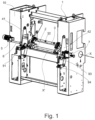
- a rotogravure printing unit comprises a printing roller and a rubber roller, not shown here, held by a frame 1.
- the rotation axis of the printing roller is sketched in figure 1 and indicated at X.
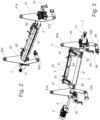
- the present invention specifically concerns a doctor blade assembly comprising a shaft 2, typically with a cylindrical shape, extending along an axis/direction X' parallel with the roller axis X and supporting, as explained hereafter, the actual blade member 31 via a pair of clamping bars 3.
- the shaft 2 is held at its ends, corresponding to respective axial ends of the printing rollers, by two elastically flexible laminar members 41, 42 lying over respective diametrical planes orthogonal to axis X'. More precisely, the laminar members 41, 42 are attached to the frame 1 at two mutually spaced regions 41a, 41b, 42a, 42b, that for instance and preferably are approximately aligned with each other (in each member), according to a vertical direction or in any case a direction approaching the vertical.
- the support of the shaft 2 occurs at an intermediate position between the two attachment regions, so that the same shaft is compliant to a reciprocating motion along its own axis X', by the effect of the deformability of the member when subject to a bending stress.
- This elastic deformability is obtained from the use of a suitable material such as spring steel along with the laminar nature of the member.
- Each deformable element comprise two attachment points to the fixed frame.
- the objective of the attachment configuration is to block the movement of the blade along any direction perpendicular the direction of the reciprocating motion (called the spurious motion here).
- the spurious motion There are several possible configuration that can achieve this goal; these configuration are characterized by the absolute angle between the line connecting the first point of connection of the laminar member (for example 41a) to the axis X' and the line connecting the second connecting point of the laminar member (for example 41b) to the axis X'.
- This angle should be larger than 30 degrees (for example, a value of 45 degrees puts the two attachment points 41a and 41b on the same side compared to the axis X').
- the attachment points are preferably located at opposite sides of axis X', for example with said absolute angle between 170 and 180 degrees (or at least larger than 135 degrees to obtain this reduction).
- the length of the laminar element (between the connection point and the axis X') must be set large enough compared to the amplitude of the motion. This is because, when the attachments points are not perfectly symmetric around axis X' (i.e.
- the blade tends to move along a circle segment, whose radius (which is linked to said length) must be large enough so that the circle segment does not depart from the tangent of said circle by more than the tolerance about the spurious motion maximum amplitude.
- a typical tolerance is a maximum spurious motion of 0.1mm for web width comprised between 60cm and 220cm, and an angular tolerance smaller than 1 arc min.
- the length is chosen to be of the order of 1m for a 5mm doctor blade motion. Nevertheless, the length cannot be chosen arbitrarily large to ensure enough stiffness.
- One of the attachment regions further provides for a compliant system adapted to permit some adjustment of the position of the axis of the shaft, and thus the correction of possible parallelism errors of the blade with respect to the axis of the printing roller.
- at least one of the laminar member provides for a device with a control knob 94 that can be actuated from the outside of the frame and operates with the opposing force of a spring 95 on the connection between the laminar member (in this case the laminar member 42) and the frame, to the end of modifying the slant of the same laminar member.
- a motor 5 is anchored to the frame 1 on the side of a first laminar member 41 (externally to the space delimited by the two laminar blades) and via an obviously designed eccentric system obviously transmits a reciprocating drive to an arm 6, in turn extending along the axis X' or parallel therewith.
- the arm 6, on an opposite side with respect to the linking side to the motor 5, is connected to the laminar member 41 at a region close to the support point of the shaft. Also, the arm has a flexible structure, to absorb the stresses and allow for the parallelism corrections.
- the shaking thus transmitted to the assembly of the arm and laminar members, permitted by the elastic flexion of the members, actuates the reciprocating motion along the axis X' with an amplitude of some mm - typically between 2 and 8 mm - that permits to provide the blade with the desired "to and fro" brushing movement.
- the amplitude of the motion (between 2 and 8 mm) is large enough to be able to dislodging the clogs.
- the amplitude can be set to 4 mm.
- an adjustable preload device 7 controlled as explained hereafter, that in an embodiment comprises a helical spring 71 having the function to exert a thrust as a result of its compression between the second laminar member 42 and frame 1.
- the stems 81 are in fact slidable along their own axes Y (indeed, tangential or in any case hitting the side surface of the shaft over a plane normal to the shaft axis) inside respective guides 82 connected to the shaft 2 (as more precisely described shortly), the sliding being hindered/cushioned by respective pneumatic dampers 83.
- This mechanism serves to provide the blade with the cushioned pressing function that is necessary to "squeeze" the ink over the printing roller.
- the guides 82 are in turn supported by the shaft 2 in such a way to ensure a displacement thereof (and with it the displacement of all the assembly of stems, dampers, bars and blade) to accomplish an adjustment depending on the specific geometry of the working circumstances.
- This displacement occurs linearly according to a tangential direction with respect to the shaft (indeed coinciding with the axis Y) within seatings 21a formed for this purpose by the shaft 2, or more properly by a sleeve 21 of the shaft.
- the latter has, in fact, a structure in two pieces, with the mentioned sleeve that coaxially houses in a rotatable fashion, via bearings 23, a core 22.
- the core 22 has two geared pinion portions 22a that mesh with respective rack 82a integral with the guides 82 so that from a rotation of the core the above cited adjustable displacement of the guides ensues.
- This adjustment as just described i.e. the rotation of the core, is actuated manually via a first crank 91 accessible from the outside at a front side 10 of the frame 1.
- the crank 91 rotatably drives a spindle 92, in turn having a tangential axis with respect to the shaft 2 over a plane orthogonal to the axis X', meshing via a gear transmission with an end of the core 22, in this case, adjacent to the motor 5.
- the preload adjustment system is arranged, comprising a crank to be actuated from the outside.
- This adjustment operates through suitable gearings on the device 7, compressing to a variable extent the above-mentioned spring 71 and thus affecting the preload.
- the support according to the invention permits to achieve the required brushing motion of the doctor blade, by simply exploiting an elastic deformation, and then without the wear due to friction that in the known art ensue from the sliding motion of a remarkable mass, such as that of the doctor blade assembly.
- the consequent reduction of vibrations and plays in general improves the printing performance and ensures an increased overall work reliability, a longer life of the machine and a reduction of the maintenance needs.
- the elastic support system permits to effectively optimise the architecture of the unit finalised to greater safety, with drive/transmission systems that permit an easy control of the unit adjustments through actuation means external to the hazardous area and comfortably available to the operator.
- an absolute value of an angle in this invention we mean an angle with a positive value comprised between 0 and 180 degrees. It is understood that when measuring an angle between two arbitrary intersecting lines, it is always possible to obtain said angle value between 0 and 180 degrees.
Landscapes
- Engineering & Computer Science (AREA)
- Mechanical Engineering (AREA)
- Rotary Presses (AREA)
Claims (9)
- Rakelklingenanordnung, die für eine Tiefdruckeinheit geeignet ist, wobei die Anordnung eine Rakelklinge (31), Rakelklingenstützmittel, die angepasst sind, mit einem festen Rahmen (1) der Einheit verbunden zu sein und eine Hin- und Herbewegung der Klinge entlang einer Bewegungsachse (X') parallel zur Ausdehnungsrichtung der Klinge zu erlauben, und Antriebsmittel umfasst, die funktionell mit der Klinge verbunden sind, um die Hin- und Herbewegung darauf zu übertragen, dadurch gekennzeichnet, dass die Stützmittel ein Paar elastisch verformbarer Laminarkomponenten (41, 42) umfassen, das zwischen jeweiligen Endbereichen der Klinge (31) und dem festen Rahmen (1) eingerichtet ist, wobei sich die Komponenten (41, 42) über jeweilige Ebenen orthogonal zur Bewegungsachse (X') erstrecken und eingerichtet sind, um die Hin- und Herbewegung zu erlauben, während die Bewegung der Klinge entlang einer beliebigen Richtung senkrecht zur Bewegungsachse (X') blockiert wird.
- Anordnung nach Anspruch 1, wobei die Klingenstützmittel eine Welle (2) umfassen, die auf der Bewegungsachse (X') zentriert ist und von der die Klinge parallel beabstandet ist, wobei die Welle an einem Verbindungspunkt mit den Laminarkomponenten verbunden ist, wobei jede Laminarkomponente zwei Befestigungspunkte mit dem festen Rahmen umfasst und wobei ein Winkel zwischen der Linie, die den ersten Befestigungspunkt mit dem Verbindungspunkt verbindet, und der Linie vom Verbindungspunkt zum zweiten Befestigungspunkt, gemessen in der Ebene senkrecht zur Bewegungsachse, einen absoluten Wert größer als 30 Grad, bevorzugt größer als 135 Grad, bevorzugt größer als 170 Grad, bevorzugt größer als 180 Grad aufweist.
- Anordnung nach Anspruch 2, wobei in jeder Laminarkomponente (41, 42) die zwei Befestigungsbereiche am festen Rahmen und der Zwischenverbindungspunkt an der Welle (2) im Wesentlichen fluchten.
- Anordnung nach Anspruch 2 oder 3, wobei die Antriebsmittel einen Getriebearm (6) umfassen, der zwischen einem Motor (5) und einer ersten (41) der Laminarkomponenten verbunden ist, der angepasst ist, eine Schüttelkraft entlang der Bewegungsachse (X') auf das erste Bauelement zu übertragen.
- Anordnung nach Anspruch 4, umfassend exzentrische Mittel, die zwischen dem Motor (5) und dem Arm (6) eingerichtet sind, die angepasst sind, um die Drehbewegung der ersten in die Schüttelbewegung umzuwandeln.
- Anordnung nach Anspruch 4 oder 5, umfassend einstellbare Vorspannmittel (7), die mit einem zweiten (42) der elastischen Bauelemente verknüpft sind.
- Anordnung nach Anspruch 6, wobei die Vorspannmittel (7) eine Schraubenfeder (71), die zwischen dem zweiten elastischen Bauelement (42) und dem festen Rahmen (1) in Kompression gedrängt wird, und Vorspanneinstellungsmittel umfassen, die angepasst sind, die Kompressionskraft, die auf die Feder wirkt, zu variieren, die mit Betätigungsmitteln (93) bereitgestellt sind, die angepasst sind, von einem Außenbereich des festen Rahmens (1) aus gesteuert zu werden.
- Anordnung nach einem der Ansprüche 2 bis 7, wobei die Welle (2) eine Hülse (21), die an den Laminarkomponenten befestigt ist, und einen Kern (22) umfasst, der angepasst ist, sich innerhalb der Hülse (21) um die Bewegungsachse (X') zu drehen, wobei die Klingenstützmittel (31) Führungsmittel (82) umfassen, die verschiebbar aus der Hülse (21) der Welle hervorstehen, wobei die Führungsmittel über Zahnräder mit dem Kern in Eingriff genommen werden, sodass die Verschiebung der Führungsmittel auf eine Drehung des Kerns anspricht, wobei Betätigungsmittel (91) weiter zum Steuern der Drehung des Kerns bereitgestellt sind, die angepasst sind, von einem Außenbereich des festen Rahmens (1) aus gesteuert zu werden.
- Anordnung nach Anspruch 8, wobei die Klinge (31) von einem Stab (3) gestützt wird, der von mindestens zwei Halmen (81) getragen wird, die im Wesentlichen tangential auf den Führungsmitteln (82) gleitend aus der Welle (2) hervorstehen, wobei Dämpfmittel (83) dem Gleiten entgegenwirken.
Applications Claiming Priority (2)
| Application Number | Priority Date | Filing Date | Title |
|---|---|---|---|
| ITUA20162812 | 2016-04-22 | ||
| PCT/EP2017/025095 WO2017182144A1 (en) | 2016-04-22 | 2017-04-21 | A doctor blade assembly with support in a rotogravure printing unit |
Publications (3)
| Publication Number | Publication Date |
|---|---|
| EP3445586A1 EP3445586A1 (de) | 2019-02-27 |
| EP3445586B1 true EP3445586B1 (de) | 2024-04-17 |
| EP3445586C0 EP3445586C0 (de) | 2024-04-17 |
Family
ID=56740337
Family Applications (1)
| Application Number | Title | Priority Date | Filing Date |
|---|---|---|---|
| EP17723010.9A Active EP3445586B1 (de) | 2016-04-22 | 2017-04-21 | Rakelanordnung mit unterstützung in einer tiefdruckeinheit |
Country Status (3)
| Country | Link |
|---|---|
| EP (1) | EP3445586B1 (de) |
| ES (1) | ES2987585T3 (de) |
| WO (1) | WO2017182144A1 (de) |
Family Cites Families (6)
| Publication number | Priority date | Publication date | Assignee | Title |
|---|---|---|---|---|
| US2049846A (en) * | 1934-12-31 | 1936-08-04 | Hoe & Co R | Inking mechanism for intaglio printing machines |
| DE756363C (de) * | 1941-09-06 | 1952-10-13 | Maschf Augsburg Nuernberg Ag | Vorrichtung zum Hin- und Herbewegen der Rakel bei Rotationstiefdruckmaschinen |
| CH551868A (de) * | 1972-05-12 | 1974-07-31 | Frankenthal Ag Albert | Rakelvorrichtung an tiefdruck-rotationsmaschine. |
| DE50208200D1 (de) * | 2002-05-18 | 2006-11-02 | Fischer & Krecke Gmbh & Co Kg | Druckmaschine mit Rakelvorrichtung |
| US8915184B2 (en) * | 2007-04-27 | 2014-12-23 | Bobst Mex Sa | Doctor blade system for print unit intended for a photogravure printing machine |
| EP2657020B1 (de) * | 2012-04-27 | 2014-10-29 | Bobst Italia S.P.A. | Bewegliche Rakelanordnung für Druckgruppen |
-
2017
- 2017-04-21 EP EP17723010.9A patent/EP3445586B1/de active Active
- 2017-04-21 WO PCT/EP2017/025095 patent/WO2017182144A1/en not_active Ceased
- 2017-04-21 ES ES17723010T patent/ES2987585T3/es active Active
Also Published As
| Publication number | Publication date |
|---|---|
| EP3445586C0 (de) | 2024-04-17 |
| WO2017182144A1 (en) | 2017-10-26 |
| ES2987585T3 (es) | 2024-11-15 |
| EP3445586A1 (de) | 2019-02-27 |
Similar Documents
| Publication | Publication Date | Title |
|---|---|---|
| AU713201B2 (en) | Rotary cutoff apparatus | |
| KR0163784B1 (ko) | 음각인쇄장치의 인쇄판실린더 와이핑장치 | |
| RU2420374C1 (ru) | Устройство для резки | |
| EP3655215B1 (de) | Schleifvorrichtung für ein schneidmesser, maschine mit einer solchen schleifvorrichtung und zugehöriges verfahren | |
| EP0241070A2 (de) | Einstellbare Lünette für Cylinderschleifmaschinen oder ähnliches | |
| JP2010503542A (ja) | 位置調整ユニット | |
| GB2061459A (en) | Bending rollers | |
| CA2503788A1 (en) | Sharpening unit and cutting machine comprising at least one blade and said sharpening unit | |
| EP3445586B1 (de) | Rakelanordnung mit unterstützung in einer tiefdruckeinheit | |
| RU2216442C2 (ru) | Способ и устройство для обработки листового материала | |
| US8069786B2 (en) | Printing groups comprising at least two cooperating cylinders and radially movable bearing units | |
| EP1882590A1 (de) | Registereinstellvorrichtung eines drehkörpers | |
| EP2415602B1 (de) | Druckpresse und Verfahren zur Positionierung von Zylindern darin | |
| JPH0617034B2 (ja) | ロールのニツプに対する保護装置 | |
| JP2003184954A (ja) | 印刷技術的な機械における振動を抑制するための方法及び装置 | |
| DE102008060291B4 (de) | Bogenbeschleunigungssystem für eine Bogendruckmaschine | |
| EP2921299A1 (de) | Vorrichtung, insbesondere geeignet zum reinigen der druckplatte von flexodruckmaschinen | |
| US9296196B2 (en) | Printing units for variable-format offset printing presses | |
| EP0069834B1 (de) | Vorrichtung zum Transport von Farbe oder Feuchtmittel | |
| CN113002130A (zh) | 用于控制印刷机组中的滚枕压力的方法 | |
| JPH0383645A (ja) | 印刷機のインキ着け装置または湿し装置における摩擦ローラ | |
| US20180056641A1 (en) | Processing unit and label printing machine having the processing unit | |
| EP2657020B1 (de) | Bewegliche Rakelanordnung für Druckgruppen | |
| EP2353865B1 (de) | Vibratoranordnung für ein Farbwerk oder Feuchtwerk einer Druckpresse | |
| JP2017019221A (ja) | ファニッシャロールを備えた輪転印刷機 |
Legal Events
| Date | Code | Title | Description |
|---|---|---|---|
| STAA | Information on the status of an ep patent application or granted ep patent |
Free format text: STATUS: UNKNOWN |
|
| STAA | Information on the status of an ep patent application or granted ep patent |
Free format text: STATUS: THE INTERNATIONAL PUBLICATION HAS BEEN MADE |
|
| PUAI | Public reference made under article 153(3) epc to a published international application that has entered the european phase |
Free format text: ORIGINAL CODE: 0009012 |
|
| STAA | Information on the status of an ep patent application or granted ep patent |
Free format text: STATUS: REQUEST FOR EXAMINATION WAS MADE |
|
| 17P | Request for examination filed |
Effective date: 20181105 |
|
| AK | Designated contracting states |
Kind code of ref document: A1 Designated state(s): AL AT BE BG CH CY CZ DE DK EE ES FI FR GB GR HR HU IE IS IT LI LT LU LV MC MK MT NL NO PL PT RO RS SE SI SK SM TR |
|
| AX | Request for extension of the european patent |
Extension state: BA ME |
|
| DAV | Request for validation of the european patent (deleted) | ||
| DAX | Request for extension of the european patent (deleted) | ||
| STAA | Information on the status of an ep patent application or granted ep patent |
Free format text: STATUS: EXAMINATION IS IN PROGRESS |
|
| 17Q | First examination report despatched |
Effective date: 20210618 |
|
| GRAP | Despatch of communication of intention to grant a patent |
Free format text: ORIGINAL CODE: EPIDOSNIGR1 |
|
| STAA | Information on the status of an ep patent application or granted ep patent |
Free format text: STATUS: GRANT OF PATENT IS INTENDED |
|
| INTG | Intention to grant announced |
Effective date: 20231127 |
|
| GRAS | Grant fee paid |
Free format text: ORIGINAL CODE: EPIDOSNIGR3 |
|
| GRAA | (expected) grant |
Free format text: ORIGINAL CODE: 0009210 |
|
| STAA | Information on the status of an ep patent application or granted ep patent |
Free format text: STATUS: THE PATENT HAS BEEN GRANTED |
|
| AK | Designated contracting states |
Kind code of ref document: B1 Designated state(s): AL AT BE BG CH CY CZ DE DK EE ES FI FR GB GR HR HU IE IS IT LI LT LU LV MC MK MT NL NO PL PT RO RS SE SI SK SM TR |
|
| REG | Reference to a national code |
Ref country code: GB Ref legal event code: FG4D |
|
| REG | Reference to a national code |
Ref country code: CH Ref legal event code: EP |
|
| REG | Reference to a national code |
Ref country code: IE Ref legal event code: FG4D Ref country code: DE Ref legal event code: R096 Ref document number: 602017081059 Country of ref document: DE |
|
| U01 | Request for unitary effect filed |
Effective date: 20240422 |
|
| U07 | Unitary effect registered |
Designated state(s): AT BE BG DE DK EE FI FR IT LT LU LV MT NL PT SE SI Effective date: 20240429 |
|
| U20 | Renewal fee for the european patent with unitary effect paid |
Year of fee payment: 8 Effective date: 20240430 |
|
| PG25 | Lapsed in a contracting state [announced via postgrant information from national office to epo] |
Ref country code: IS Free format text: LAPSE BECAUSE OF FAILURE TO SUBMIT A TRANSLATION OF THE DESCRIPTION OR TO PAY THE FEE WITHIN THE PRESCRIBED TIME-LIMIT Effective date: 20240817 |
|
| PG25 | Lapsed in a contracting state [announced via postgrant information from national office to epo] |
Ref country code: HR Free format text: LAPSE BECAUSE OF FAILURE TO SUBMIT A TRANSLATION OF THE DESCRIPTION OR TO PAY THE FEE WITHIN THE PRESCRIBED TIME-LIMIT Effective date: 20240417 |
|
| PG25 | Lapsed in a contracting state [announced via postgrant information from national office to epo] |
Ref country code: GR Free format text: LAPSE BECAUSE OF FAILURE TO SUBMIT A TRANSLATION OF THE DESCRIPTION OR TO PAY THE FEE WITHIN THE PRESCRIBED TIME-LIMIT Effective date: 20240718 |
|
| PG25 | Lapsed in a contracting state [announced via postgrant information from national office to epo] |
Ref country code: PL Free format text: LAPSE BECAUSE OF FAILURE TO SUBMIT A TRANSLATION OF THE DESCRIPTION OR TO PAY THE FEE WITHIN THE PRESCRIBED TIME-LIMIT Effective date: 20240417 |
|
| PG25 | Lapsed in a contracting state [announced via postgrant information from national office to epo] |
Ref country code: PL Free format text: LAPSE BECAUSE OF FAILURE TO SUBMIT A TRANSLATION OF THE DESCRIPTION OR TO PAY THE FEE WITHIN THE PRESCRIBED TIME-LIMIT Effective date: 20240417 Ref country code: NO Free format text: LAPSE BECAUSE OF FAILURE TO SUBMIT A TRANSLATION OF THE DESCRIPTION OR TO PAY THE FEE WITHIN THE PRESCRIBED TIME-LIMIT Effective date: 20240717 Ref country code: IS Free format text: LAPSE BECAUSE OF FAILURE TO SUBMIT A TRANSLATION OF THE DESCRIPTION OR TO PAY THE FEE WITHIN THE PRESCRIBED TIME-LIMIT Effective date: 20240817 Ref country code: HR Free format text: LAPSE BECAUSE OF FAILURE TO SUBMIT A TRANSLATION OF THE DESCRIPTION OR TO PAY THE FEE WITHIN THE PRESCRIBED TIME-LIMIT Effective date: 20240417 Ref country code: GR Free format text: LAPSE BECAUSE OF FAILURE TO SUBMIT A TRANSLATION OF THE DESCRIPTION OR TO PAY THE FEE WITHIN THE PRESCRIBED TIME-LIMIT Effective date: 20240718 Ref country code: RS Free format text: LAPSE BECAUSE OF FAILURE TO SUBMIT A TRANSLATION OF THE DESCRIPTION OR TO PAY THE FEE WITHIN THE PRESCRIBED TIME-LIMIT Effective date: 20240717 |
|
| REG | Reference to a national code |
Ref country code: ES Ref legal event code: FG2A Ref document number: 2987585 Country of ref document: ES Kind code of ref document: T3 Effective date: 20241115 |
|
| REG | Reference to a national code |
Ref country code: CH Ref legal event code: PL |
|
| REG | Reference to a national code |
Ref country code: DE Ref legal event code: R097 Ref document number: 602017081059 Country of ref document: DE |
|
| PG25 | Lapsed in a contracting state [announced via postgrant information from national office to epo] |
Ref country code: CZ Free format text: LAPSE BECAUSE OF FAILURE TO SUBMIT A TRANSLATION OF THE DESCRIPTION OR TO PAY THE FEE WITHIN THE PRESCRIBED TIME-LIMIT Effective date: 20240417 |
|
| PG25 | Lapsed in a contracting state [announced via postgrant information from national office to epo] |
Ref country code: SK Free format text: LAPSE BECAUSE OF FAILURE TO SUBMIT A TRANSLATION OF THE DESCRIPTION OR TO PAY THE FEE WITHIN THE PRESCRIBED TIME-LIMIT Effective date: 20240417 Ref country code: RO Free format text: LAPSE BECAUSE OF FAILURE TO SUBMIT A TRANSLATION OF THE DESCRIPTION OR TO PAY THE FEE WITHIN THE PRESCRIBED TIME-LIMIT Effective date: 20240417 |
|
| PG25 | Lapsed in a contracting state [announced via postgrant information from national office to epo] |
Ref country code: SM Free format text: LAPSE BECAUSE OF FAILURE TO SUBMIT A TRANSLATION OF THE DESCRIPTION OR TO PAY THE FEE WITHIN THE PRESCRIBED TIME-LIMIT Effective date: 20240417 |
|
| PG25 | Lapsed in a contracting state [announced via postgrant information from national office to epo] |
Ref country code: SM Free format text: LAPSE BECAUSE OF FAILURE TO SUBMIT A TRANSLATION OF THE DESCRIPTION OR TO PAY THE FEE WITHIN THE PRESCRIBED TIME-LIMIT Effective date: 20240417 Ref country code: SK Free format text: LAPSE BECAUSE OF FAILURE TO SUBMIT A TRANSLATION OF THE DESCRIPTION OR TO PAY THE FEE WITHIN THE PRESCRIBED TIME-LIMIT Effective date: 20240417 Ref country code: RO Free format text: LAPSE BECAUSE OF FAILURE TO SUBMIT A TRANSLATION OF THE DESCRIPTION OR TO PAY THE FEE WITHIN THE PRESCRIBED TIME-LIMIT Effective date: 20240417 Ref country code: CZ Free format text: LAPSE BECAUSE OF FAILURE TO SUBMIT A TRANSLATION OF THE DESCRIPTION OR TO PAY THE FEE WITHIN THE PRESCRIBED TIME-LIMIT Effective date: 20240417 Ref country code: CH Free format text: LAPSE BECAUSE OF NON-PAYMENT OF DUE FEES Effective date: 20240430 Ref country code: MC Free format text: LAPSE BECAUSE OF FAILURE TO SUBMIT A TRANSLATION OF THE DESCRIPTION OR TO PAY THE FEE WITHIN THE PRESCRIBED TIME-LIMIT Effective date: 20240417 |
|
| PLBE | No opposition filed within time limit |
Free format text: ORIGINAL CODE: 0009261 |
|
| STAA | Information on the status of an ep patent application or granted ep patent |
Free format text: STATUS: NO OPPOSITION FILED WITHIN TIME LIMIT |
|
| 26N | No opposition filed |
Effective date: 20250120 |
|
| GBPC | Gb: european patent ceased through non-payment of renewal fee |
Effective date: 20240717 |
|
| PG25 | Lapsed in a contracting state [announced via postgrant information from national office to epo] |
Ref country code: IE Free format text: LAPSE BECAUSE OF NON-PAYMENT OF DUE FEES Effective date: 20240421 |
|
| PG25 | Lapsed in a contracting state [announced via postgrant information from national office to epo] |
Ref country code: GB Free format text: LAPSE BECAUSE OF NON-PAYMENT OF DUE FEES Effective date: 20240717 |
|
| U20 | Renewal fee for the european patent with unitary effect paid |
Year of fee payment: 9 Effective date: 20250407 |
|
| PGFP | Annual fee paid to national office [announced via postgrant information from national office to epo] |
Ref country code: ES Payment date: 20250509 Year of fee payment: 9 |
|
| PGFP | Annual fee paid to national office [announced via postgrant information from national office to epo] |
Ref country code: TR Payment date: 20250409 Year of fee payment: 9 |
|
| PG25 | Lapsed in a contracting state [announced via postgrant information from national office to epo] |
Ref country code: CY Free format text: LAPSE BECAUSE OF FAILURE TO SUBMIT A TRANSLATION OF THE DESCRIPTION OR TO PAY THE FEE WITHIN THE PRESCRIBED TIME-LIMIT; INVALID AB INITIO Effective date: 20170421 |
|
| PG25 | Lapsed in a contracting state [announced via postgrant information from national office to epo] |
Ref country code: HU Free format text: LAPSE BECAUSE OF FAILURE TO SUBMIT A TRANSLATION OF THE DESCRIPTION OR TO PAY THE FEE WITHIN THE PRESCRIBED TIME-LIMIT; INVALID AB INITIO Effective date: 20170421 |