EP3445227B1 - Verfahren und system zur optimierung der dbs-programmierung - Google Patents
Verfahren und system zur optimierung der dbs-programmierung Download PDFInfo
- Publication number
- EP3445227B1 EP3445227B1 EP17716798.8A EP17716798A EP3445227B1 EP 3445227 B1 EP3445227 B1 EP 3445227B1 EP 17716798 A EP17716798 A EP 17716798A EP 3445227 B1 EP3445227 B1 EP 3445227B1
- Authority
- EP
- European Patent Office
- Prior art keywords
- directional
- frequency
- stimulation
- lead
- lfp
- Prior art date
- Legal status (The legal status is an assumption and is not a legal conclusion. Google has not performed a legal analysis and makes no representation as to the accuracy of the status listed.)
- Active
Links
Images


Classifications
-
- A—HUMAN NECESSITIES
- A61—MEDICAL OR VETERINARY SCIENCE; HYGIENE
- A61N—ELECTROTHERAPY; MAGNETOTHERAPY; RADIATION THERAPY; ULTRASOUND THERAPY
- A61N1/00—Electrotherapy; Circuits therefor
- A61N1/02—Details
- A61N1/04—Electrodes
- A61N1/05—Electrodes for implantation or insertion into the body, e.g. heart electrode
- A61N1/0526—Head electrodes
- A61N1/0529—Electrodes for brain stimulation
- A61N1/0534—Electrodes for deep brain stimulation
-
- A—HUMAN NECESSITIES
- A61—MEDICAL OR VETERINARY SCIENCE; HYGIENE
- A61B—DIAGNOSIS; SURGERY; IDENTIFICATION
- A61B5/00—Measuring for diagnostic purposes; Identification of persons
- A61B5/0002—Remote monitoring of patients using telemetry, e.g. transmission of vital signals via a communication network
- A61B5/0031—Implanted circuitry
-
- A—HUMAN NECESSITIES
- A61—MEDICAL OR VETERINARY SCIENCE; HYGIENE
- A61B—DIAGNOSIS; SURGERY; IDENTIFICATION
- A61B5/00—Measuring for diagnostic purposes; Identification of persons
- A61B5/24—Detecting, measuring or recording bioelectric or biomagnetic signals of the body or parts thereof
- A61B5/2415—Measuring direct current [DC] or slowly varying biopotentials
-
- A—HUMAN NECESSITIES
- A61—MEDICAL OR VETERINARY SCIENCE; HYGIENE
- A61B—DIAGNOSIS; SURGERY; IDENTIFICATION
- A61B5/00—Measuring for diagnostic purposes; Identification of persons
- A61B5/24—Detecting, measuring or recording bioelectric or biomagnetic signals of the body or parts thereof
- A61B5/316—Modalities, i.e. specific diagnostic methods
- A61B5/369—Electroencephalography [EEG]
- A61B5/372—Analysis of electroencephalograms
- A61B5/374—Detecting the frequency distribution of signals, e.g. detecting delta, theta, alpha, beta or gamma waves
-
- A—HUMAN NECESSITIES
- A61—MEDICAL OR VETERINARY SCIENCE; HYGIENE
- A61B—DIAGNOSIS; SURGERY; IDENTIFICATION
- A61B5/00—Measuring for diagnostic purposes; Identification of persons
- A61B5/40—Detecting, measuring or recording for evaluating the nervous system
- A61B5/4058—Detecting, measuring or recording for evaluating the nervous system for evaluating the central nervous system
- A61B5/4064—Evaluating the brain
-
- A—HUMAN NECESSITIES
- A61—MEDICAL OR VETERINARY SCIENCE; HYGIENE
- A61B—DIAGNOSIS; SURGERY; IDENTIFICATION
- A61B5/00—Measuring for diagnostic purposes; Identification of persons
- A61B5/48—Other medical applications
- A61B5/4836—Diagnosis combined with treatment in closed-loop systems or methods
-
- A—HUMAN NECESSITIES
- A61—MEDICAL OR VETERINARY SCIENCE; HYGIENE
- A61B—DIAGNOSIS; SURGERY; IDENTIFICATION
- A61B5/00—Measuring for diagnostic purposes; Identification of persons
- A61B5/72—Signal processing specially adapted for physiological signals or for diagnostic purposes
- A61B5/7225—Details of analogue processing, e.g. isolation amplifier, gain or sensitivity adjustment, filtering, baseline or drift compensation
-
- A—HUMAN NECESSITIES
- A61—MEDICAL OR VETERINARY SCIENCE; HYGIENE
- A61N—ELECTROTHERAPY; MAGNETOTHERAPY; RADIATION THERAPY; ULTRASOUND THERAPY
- A61N1/00—Electrotherapy; Circuits therefor
- A61N1/18—Applying electric currents by contact electrodes
- A61N1/32—Applying electric currents by contact electrodes alternating or intermittent currents
- A61N1/36—Applying electric currents by contact electrodes alternating or intermittent currents for stimulation
- A61N1/3605—Implantable neurostimulators for stimulating central or peripheral nerve system
- A61N1/3606—Implantable neurostimulators for stimulating central or peripheral nerve system adapted for a particular treatment
- A61N1/36067—Movement disorders, e.g. tremor or Parkinson disease
-
- A—HUMAN NECESSITIES
- A61—MEDICAL OR VETERINARY SCIENCE; HYGIENE
- A61N—ELECTROTHERAPY; MAGNETOTHERAPY; RADIATION THERAPY; ULTRASOUND THERAPY
- A61N1/00—Electrotherapy; Circuits therefor
- A61N1/18—Applying electric currents by contact electrodes
- A61N1/32—Applying electric currents by contact electrodes alternating or intermittent currents
- A61N1/36—Applying electric currents by contact electrodes alternating or intermittent currents for stimulation
- A61N1/3605—Implantable neurostimulators for stimulating central or peripheral nerve system
- A61N1/36128—Control systems
- A61N1/36135—Control systems using physiological parameters
-
- A—HUMAN NECESSITIES
- A61—MEDICAL OR VETERINARY SCIENCE; HYGIENE
- A61N—ELECTROTHERAPY; MAGNETOTHERAPY; RADIATION THERAPY; ULTRASOUND THERAPY
- A61N1/00—Electrotherapy; Circuits therefor
- A61N1/18—Applying electric currents by contact electrodes
- A61N1/32—Applying electric currents by contact electrodes alternating or intermittent currents
- A61N1/36—Applying electric currents by contact electrodes alternating or intermittent currents for stimulation
- A61N1/3605—Implantable neurostimulators for stimulating central or peripheral nerve system
- A61N1/36128—Control systems
- A61N1/36146—Control systems specified by the stimulation parameters
- A61N1/36182—Direction of the electrical field, e.g. with sleeve around stimulating electrode
- A61N1/36185—Selection of the electrode configuration
Definitions
- the invention relates to the field of deep brain stimulation (DBS), which can be used for example to alleviate the symptoms of conditions such as Parkinson's Disease (PD).
- DBS deep brain stimulation
- the invention relates to a method of determining optimised parameters for programming a stimulation regime for a directional deep brain stimulation electrode.
- Deep brain stimulation is a proven treatment option for patients with advanced Parkinson's disease (PD), and may consist of inserting DBS leads into target cerebral regions such as the subthalamic nucleus (STN), the globus pallidus internus (GPi) or the thalamus, such that electrical current can be applied to treat disease-specific motor symptoms in patients with PD.
- STN subthalamic nucleus
- GPi globus pallidus internus
- the spatial selectivity of DBS is of the utmost importance for the quality of the clinical result; firstly, spatial selectivity helps to ensure accurate targeting of the region for therapeutic stimulation. Secondly, it helps to avoid unwanted stimulation of neighbouring structures which could result in adverse effects.
- a quadripolar DBS lead with four cylindrical electrodes, also referred to as contacts, arranged in successive axial sections along its length, ie four axial sections with one electrode per axial section.
- Such an electrode can positioned using a known navigation technique; postoperatively, the four electrodes are tested manually by the operator to identify the electrodes which are best located in the target region.
- the procedure may typically be carried out as follows: All the electrodes in both cerebral hemispheres are tested using different stimulation parameters, while the resulting clinical effects and side effects are assessed by interviewing the patient and by neurological examination.
- the patient is usually withdrawn from his/her medication before the procedure is carried out.
- the first electrode is selected and the stimulation amplitude (voltage or current) is slowly increased in 0.5 V (or 0.5 mA) steps, while the stimulation frequency and the pulse width remain fixed at 130 Hz and 60 psec respectively.
- the effects and side effects are determined by asking the patient and by performing a neurological examination.
- the stepwise increase of the stimulation amplitude is continued until limiting side effects occur.
- the known method involves manually attempting to estimate the best configuration for symptom relief among the myriad possible different stimulation parameters.
- the patient's symptoms are alleviated by stimulation provided by a implanted pulse generator (IPG) and DBS electrode, programmed according to the estimation process described above. Further re-programming of the IPG may subsequently be required if the estimated parameters prove to be ineffective, and each re-programming necessitates a further clinical session for the patient.
- IPG implanted pulse generator
- a directional multi-electrode lead is known from EP2626109 , for example.
- a simple example is shown in figure 1 , and will be used as an illustrative example in the following description of the invention.
- the lead shown in figure 1 has eight electrodes (contacts) arranged in four axial sections similar to the sections of the quadripolar lead described above.
- the second and third axial sections of the directional electrode each comprise three contacts 3 1 , 3 2 , 3 3 and 4 1 , 4 2 , 4 3 , formed as circumferential cylindrical surface segments, thereby allowing a different stimulation amplitude (voltage or current) to be programmed to each of three different lateral directions for each of the two multi-contact sections.
- Such a directional lead permits the stimulation field to be shaped towards a desired direction within the target region, thereby allowing the DBS to be programmed with significantly greater stimulation accuracy to achieve the best clinical effect, while avoiding stimulating in directions which may induce unwanted stimulation-related side effects.
- a system and method are therefore needed for reducing the time taken to determine the programming parameters, and for improving their accuracy and reliability.
- the invention aims to overcome at least some of the above and other difficulties inherent in the prior art.
- the invention aims to provide a method as set out in claim 1, a system as set out in claim 9 and a computer-readable medium as set out in claim 15. Further variants of the apparatus and method of the invention are described in dependent claims 2 to 8, and 10-14.
- the programming parameter determining procedure can be performed a great deal more quickly, accurately and reproducibly than was hitherto possible with contact testing carried out manually by a skilled operator.
- an intraoperative recording of the neuronal activity may be performed, for example using a directional multi-contact lead such as the one shown in figure 1 .
- a recording may reveal evidence of exaggerated oscillatory synchronisation in the STN, GPi or thalamus, which may be detected in the local field potentials (LFP).
- LFP local field potentials
- Two broad types of oscillatory activity in patients with PD have been identified: beta band activity (13-30 Hz) and gamma band activity (65-80 Hz).
- the power of the beta band activity without medical treatment correlate with clinical signs of Parkinsonism (bradykinesia and rigidity) and the degree of clinical improvement with treatment, respectively.
- Gamma band activity has been shown to increase during improvement of bradykinesia and rigidity.
- the method and system of the invention make use of the fact that LFP signals in specific frequency bands, especially the beta band activity, are linked to the motor signs and may be used as biomarkers to optimise deep brain stimulation. LFPs recorded from directional DBS leads are screened for individual direction and depth-specific differences in the power frequency spectrum in disease-related frequency bands (eg beta band).
- a specific algorithm is then used to process these signal data in order to output parameters for the optimum contact configuration for programming the subsequent DBS stimulation regime.
- the method and system of the invention may be employed for automatic programming of the IPG connected to a directional DBS lead.
- the method and system of the invention may be employed to provide optimised programming parameters to a clinician, thereby providing a supportive tool for the clinician for programming of the IPG for the directional DBS lead.
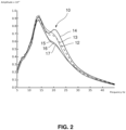
- Figure 2 shows an example set of frequency-power spectra of LPF signal data acquired from the lead 1 of figure 1 , for a particular DBS site of a particular patient.
- Curves 12, 13, 14, 15, 16, and 17 show the spectra of the LFP signal data acquired in the beta band from contacts 3 1 , 3 2 , 3 3 , 4 1 , 4 2 and 4 3 respectively.
- a local peak 10 can be seen in the curve 14 for contact 4 3 at approximately 20 Hz.
- this peak 10 can be detected using an algorithm for detecting peaks in each spectral power curve and determining at which of the peaks the difference between the amplitudes (ie the spread of the amplitude values) among one set of directional contacts (ie 3 1 , 3 2 and 3 3 or 4 1 , 4 2 and 4 3 ) are greatest.
- this maximum difference calculation may be based on normalized and/or baseline-corrected amplitude values of the frequency curves within a frequency window (referred to as the DIFR) at the peak under consideration.
- Signal differences and signal comparability can be improved by carrying out normalization and/or baseline correction steps in order to increase the signal-to-noise ratio. Normalization steps may include various spectral components, and may involve for example contrasting the the peak amplitude with the mean amplitude of the whole disease-related frequency band.
- Stimulation weightings may be mapped using appropriate transformation from the geometric configuration of the directional sensor(s) to the geometric configuration of the directional stimulation electrode(s).
- the method steps are described in the context of monopolar measurements (ie assessing each contact separately, with a common reference).
- monopolar method power frequency curves are derived for each contact, and the magnitude of the disease-related spectral component is ranked for the contacts individually.
- the same techniques may be applied to more than single contact at once, in a bipolar or multipolar fashion, such that so-called “montages” or arrangements of multiple contacts may be assessed and ranked.
- Method steps applied to individual contacts in this description should be understood to encompass the application of the steps to montages of two or more contacts.
- Determining the magnitude of the disease-related spectral components in such a group-wise, combinatorial fashion greatly increases the number of possible choices to be ranked, and improves the signal-to-noise ratio of the derived results (power frequency curves and detected peaks).
- Figures 3a and 3b show how the spectral power curves of figure 2 may be used to derive directional weightings 6 and 7 for the stimulation amplitudes at contacts 3 1 , 3 2 and 3 3 ( figure 3a ) and contacts 4 1 , 4 2 and 4 3 ( figure 3b ).
- the three electrodes 3 1 , 3 2 and 3 3 show almost zero directional weighting (8%, 9% and 8% respectively)
- figure 3b shows that the three electrodes 4 1 , 4 2 and 4 3 are markedly weighted (16%, 23% and 35% respectively).
- the inventive method predicts that the DBS should be weighted in favour of the contact 4 3 in order to achieve optimum targeting of the structure to be stimulated.
- a manual contact testing was carried out blind on the patient whose LFP signals were recorded to generate the spectral curves of figure 2 , and the manual contact testing produced the following recommended directional stimulation currents for each of the directional contacts of the DBS lead of figure 1 as follows:
- the manual contact testing approach confirmed the prediction, made by the method of the invention, that contact 4 3 would provide the best result (lowest stimulation current for effective symptom relief).
- the manual contact testing took six hours of intensive, fatiguing clinical work, while the recommendation from the inventive method was delivered almost instantly.
- figures 3a and 3b are examples of how the directional contact weighting may be presented graphically to a clinician so that he or she may adjust the DBS programming accordingly.
- the calculated weightings may be used directly in an automated programming of the IPG and DBS electrode.
- FIG 4 shows an overview of the context of the method and system of the invention in the overall DBS process.
- step 20 directional LFP signals are acquired from directional sensing electrode 1, such as the lead shown in figure 1 .
- the acquired signals are processed in step 21, using to a method according to the invention, to generate directionally optimised programming parameters which are then used in step 22 to program an IPG driving a directional DBS lead 8 (which may typically be the lead 1, ie the DBS lead serves as sensor and stimulation lead).
- a directional DBS lead 8 which may typically be the lead 1, ie the DBS lead serves as sensor and stimulation lead.
- the LFP signal acquisition step 20 may comprise recording LFPs from the directional lead after its placement in the definitive position within the target structure (eg STN, GPi or thalamus). During the recording, the patient must be withdrawn from dopaminergic medication, the patient must be awake and in a resting position without any voluntary movement. Recording can be performed intraoperatively or postoperatively before the electrode is connected to the implantable pulse generator (IPG). Alternatively, LFPs can be recorded at any time point from the IPG itself, if the IPG is capable of LFP recording.
- the target structure eg STN, GPi or thalamus
- step 21 of figure 4 The method steps underlying step 21 of figure 4 are described below, with particular reference to figures 5 and 6 .
- the method of the invention comprises the steps of
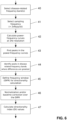
- FIG. 6 shows an example flow diagram of a method according to the invention.
- one or more suitable frequency bands are selected, according to current knowledge, for analysing the LFP signals associated with a particular disease.
- the frequency band(s) may advantageously comprise the beta frequency range (13-35 Hz).
- several frequency bands present in the LFP may be used as biomarkers (alone or in combination) to guide stimulation, however on the premise of an existing relationship to the disease. Such a relationship could be positive (associated with symptom alleviation) or negative (associated with symptom deterioration).
- a suitable sampling frequency is determined for the subsequent spectral analysis, the sampling frequency being preferably at least twice the Nyquist limit for the LFP signal data.
- step 42 the power-frequency-spectrum (spectral analysis with frequency decomposition) for each directional contact is calculated, at eg 1 Hz resolution.
- step 43 local peaks in the power-frequency curves are identified. Within the disease-related frequency band, the peak showing the largest differences among directional contacts is identified in step 44.
- step 45 the frequency of the peak identified in step 44 is transformed into a frequency range (DIFR) by adding and subtracting a predetermined spectral bandwidth, such as 3 Hz, to give a total width of 7Hz.
- DIFR eg frequency ⁇ 3 Hz
- the width of DIFR can be set to maximize directional information between the contacts.
- the width of the DFIR may be predetermined, or it may be dynamically adapted, for example in dependence on a characteristic of the power-frequency curves.
- the average amplitude for each directional contact over the DIFR is baseline corrected by subtracting 90% of the mean amplitude of the directional contact with the lowest amplitude in the DFIR. This step helps to reduce the effect of volume conduction and to improve the visualisation of the spectral differences between the contacts.
- the baseline corrected average amplitudes for each contact are then summed in step 47, and percentage distribution over the directional contacts is calculated to determine a directionality index (DI).
- DI directionality index
- each directional contact allows contacts to be ranked according to the likelihood that they will afford the best clinical response on stimulation, which is defined as the lowest stimulation intensity required for sufficient clinical response.
- the percentage value itself does not indicate a percentage clinical response.
- two or more of the directional contacts in a particular lead section have similar DI values, they may be considered in combination for stimulation.
- the directionality index is superimposed graphically as a vector and as percentage value for each directional contact on a visual model illustrating the stimulation contacts and contact levels. This enables the clinician to immediately understand which section and which directional contact are likely to produce the best OBS results.
- the parameters determined in the method described above may be exported (manually or automatically) into the IPG which drives the OBS stimulation device.
- the clinician should therefore start to deliver the stimulation on the contact with the highest directionality index, adjusting other stimulation parameters (current, frequency, pulse width etc) accordingly and, if necessary, move on to a different contact, or a different combinion of contacts, suggested by the directionality index results if the stimulation effect is clinically not sufficient or if side effects occur.
- the inventive method, and the system which embodies it could be fully integrated and automated as an internal feature of the IPG.
- the method described above may preferably be implemented as instructions stored on non-transitory computer-readable media, and/or in a system comprising one or more specially configured or programmed electronic circuits.
Landscapes
- Health & Medical Sciences (AREA)
- Life Sciences & Earth Sciences (AREA)
- Engineering & Computer Science (AREA)
- General Health & Medical Sciences (AREA)
- Animal Behavior & Ethology (AREA)
- Biomedical Technology (AREA)
- Veterinary Medicine (AREA)
- Public Health (AREA)
- Neurology (AREA)
- Neurosurgery (AREA)
- Heart & Thoracic Surgery (AREA)
- Biophysics (AREA)
- Medical Informatics (AREA)
- Molecular Biology (AREA)
- Physics & Mathematics (AREA)
- Surgery (AREA)
- Pathology (AREA)
- Nuclear Medicine, Radiotherapy & Molecular Imaging (AREA)
- Radiology & Medical Imaging (AREA)
- Psychology (AREA)
- Physiology (AREA)
- Psychiatry (AREA)
- Signal Processing (AREA)
- Cardiology (AREA)
- Computer Networks & Wireless Communication (AREA)
- Hospice & Palliative Care (AREA)
- Power Engineering (AREA)
- Artificial Intelligence (AREA)
- Computer Vision & Pattern Recognition (AREA)
- Electrotherapy Devices (AREA)
Claims (15)
- Computerimplementiertes Verfahren zur Bestimmung optimierter patientenspezifischer Programmierparameter (6, 7) zur Programmierung einer gerichteten Stimulationsleitung (1, 8) mit Parametern zur Stimulierung des besagten Bereichs, basierend auf einer Vielzahl von gerichteten LFP-Signalen, die in einer Vielzahl von verschiedenen Richtungen an einem Richtungssensor (1) gemessen wurden, der sich in einem vorbestimmten Bereich des Gehirns eines Patienten befindet, wobei das Verfahren umfasst:einen Spektralanalyseschritt (30), in dem über mindestens einen vorbestimmten Frequenzbereich eine Leistungs-Frequenz-Variationskurve (12, 13, 14, 15, 16, 17) für jedes der gerichteten LFP-Signale bestimmt wird,einen Schritt zur Identifizierung von Spitzenwerten (31), in dem die Frequenz mindestens eines lokalen Maximums, im Folgenden als Spitzenwert (10) bezeichnet, in den Leistungs-Frequenz-Variationskurven identifiziert wird,einen Differenzerkennungsschritt (32) zum Erkennen eines der mindestens einen identifizierten Spitzenwerte, bei dem eine maximale Differenz der Signalleistung zwischen den gerichteten LFP-Signalen
auftritt,einen Richtungsbestimmungsschritt (33) zum Berechnen mehrerer richtungsgewichteter Stimulationsindizes (6, 7) für die gerichtete Stimulationsleitung auf der Grundlage der relativen Signalstärken der gerichteten LFP-Signale bei der Frequenz des erfassten Spitzenwerts (10). - Verfahren nach Anspruch 1, wobei der genannte Frequenzbereich den Beta-Frequenzbereich umfasst.
- Verfahren nach Anspruch 1 oder 2, wobei der Schritt der Spektralanalyse die Bestimmung von Leistungs-Frequenz-Kurven für eine Vielzahl von Frequenzbereichen umfasst, wobei die Frequenzbereiche allein oder in Kombination zur Steuerung der Stimulation verwendet werden können.
- Verfahren nach einem der vorhergehenden Ansprüche, wobei der Schritt der Richtungsbestimmung (32, 33) umfasst:- Auswahl eines richtungsanzeigenden Frequenzbereichs, im Folgenden als DIFR bezeichnet, auf der Grundlage des erfassten Spitzenwerts (10) und -Bestimmung eines Direktionalitätsindexes, im Folgenden als DI bezeichnet, für jede einer Vielzahl der Elektroden der gerichteten Stimulationsleitung (8) und/oder für jede einer Vielzahl von Zusammenstellungen der Elektroden der gerichteten Stimulationsleitung (8).
- Verfahren nach Anspruch 4, wobei der DIFR ein vorbestimmter konstanter Frequenzbereich ist, der auf die Frequenz des erfassten Spitzenwerts zentriert ist, oder wobei die Breite des DIFR in Abhängigkeit von der Frequenz des erfassten Spitzenwerts gewählt wird.
- Verfahren nach Anspruch 4 oder Anspruch 5, wobei der Schritt der Bestimmung des Richtungsindexes die Durchführung einer Normalisierung und/oder einer Basislinienkorrektur der durchschnittlichen Amplitude jeder der spektralen Leistungs-LFP-Kurven (12, 13, 14, 15, 16, 17) in dem DIFR umfasst.
- Verfahren nach Anspruch 6, wobei die Basislinienkorrektur das Subtrahieren eines vorbestimmten Anteils der mittleren spektralen Amplitude von der Amplitude jeder der Kurven umfasst.
- Verfahren nach Anspruch 7, das ferner das Aufsummieren der durchschnittlichen Amplitude jeder Kurve über den DIFR umfasst, um eine proportionale Verteilung für jede mit der jeweiligen Kurve verbundene Richtung zu erhalten.
- System zur Bestimmung optimierter patientenspezifischer Programmierparameter (6, 7) zur Programmierung einer gerichteten Stimulationsleitung (8) mit Parametern zur Stimulation der genannten Region, wobei das System umfasst:Mittel, die so konfiguriert sind, dass sie eine Vielzahl von zuvor erfassten gerichteten LFP-Signalen empfangen, die in einer Vielzahl von verschiedenen Richtungen an einer Richtungssensorleitung (1) gemessen wurden, die sich in einer vorbestimmten Region des Gehirns eines Patienten befindet,Mittel zur Berechnung der Spektralanalyse, die so konfiguriert sind, dass sie über mindestens einen vorbestimmten Frequenzbereich eine Leistungs-Frequenz-Variationskurve (12, 13, 14, 15, 16, 17) für jedes der gerichteten LFP-Signale bestimmen,Mittel zur Erkennung von Spitzenwerten, die so konfiguriert sind, dass sie eine Frequenz mindestens eines lokalen Maximums, im Folgenden als Spitzenwert (10) bezeichnet, in den von den Mitteln zur Berechnung der Spektralanalyse ermittelten Leistungs-Frequenz-Variationskurven identifizieren,Differenzerkennungsmittel, die so konfiguriert sind, dass sie einen der mindestens einen identifizierten Spitzenwerte erkennen, bei denen eine maximale Differenz der Signalleistung zwischen den gerichteten LFP-Signalen auftritt,eine Richtungsbestimmungseinrichtung, die so konfiguriert ist, dass sie eine Vielzahl von richtungsgewichteten Stimulationsparametern (6, 7) für die Richtungsstimulationsleitung (8) auf der Grundlage der relativen Signalstärken der gerichteten LFP-Signale bei der Frequenz des erfassten Spitzenwerts (10) berechnet.
- System nach Anspruch 9, bei dem eines oder mehrere der Mittel zur Berechnung der Spektralanalyse, der Mittel zur Erfassung von Spitzenwerten, der Mittel zur Erfassung von Differenzen und der Mittel zur Bestimmung der Richtungsabhängigkeit in eine implantierbare Impulsgeneratorvorrichtung zur Ansteuerung der gerichteten Stimulationsleitung (8) integriert sind.
- System nach Anspruch 10, das ferner eine Sensorleitung (1) zur gerichteten NF-Aufnahme umfasst.
- System nach einem der Ansprüche 9 bis 11, das ferner die Stimulationsleitung (8) zur Durchführung einer gerichteten Stimulation auf der Grundlage der richtungsabhängig gewichteten Stimulationsparameter umfasst.
- System nach Anspruch 11 oder 12, wobei die Sensorleitung (1) und die Stimulationsleitung (8) die gleiche Vorrichtung sind.
- System nach einem der Ansprüche 9 bis 13, ferner mit einer programmierbaren implantierbaren Impulsgeneratorvorrichtung zum Ansteuern der Stimulationsleitung (8), wobei der programmierbare implantierbare Impulsgenerator Mittel zum Erfassen oder Aufzeichnen von LFP-Signaldaten von der Sensorleitung (1) umfasst.
- Nicht-transitorisches computerlesbares Medium, das prozessorausführbare Befehle auf einem Computergerät speichert, das so konfiguriert ist, dass es das Verfahren nach einem der Ansprüche 1 bis 8 ausführt.
Applications Claiming Priority (2)
| Application Number | Priority Date | Filing Date | Title |
|---|---|---|---|
| EP16160544 | 2016-03-15 | ||
| PCT/EP2017/056184 WO2017158067A1 (en) | 2016-03-15 | 2017-03-15 | Method and system for optimisation of dbs programming |
Publications (2)
| Publication Number | Publication Date |
|---|---|
| EP3445227A1 EP3445227A1 (de) | 2019-02-27 |
| EP3445227B1 true EP3445227B1 (de) | 2024-01-10 |
Family
ID=55637173
Family Applications (1)
| Application Number | Title | Priority Date | Filing Date |
|---|---|---|---|
| EP17716798.8A Active EP3445227B1 (de) | 2016-03-15 | 2017-03-15 | Verfahren und system zur optimierung der dbs-programmierung |
Country Status (5)
| Country | Link |
|---|---|
| US (1) | US11478633B2 (de) |
| EP (1) | EP3445227B1 (de) |
| JP (1) | JP2019509157A (de) |
| CN (1) | CN109310322A (de) |
| WO (1) | WO2017158067A1 (de) |
Families Citing this family (16)
| Publication number | Priority date | Publication date | Assignee | Title |
|---|---|---|---|---|
| US11318296B2 (en) * | 2018-10-26 | 2022-05-03 | Medtronic, Inc. | Signal-based automated deep brain stimulation programming |
| US11344728B2 (en) | 2019-05-28 | 2022-05-31 | Aleva Neurotherapeutics | Neurostimulation device with recording patch |
| CN110495872B (zh) * | 2019-08-27 | 2022-03-15 | 中科麦迪人工智能研究院(苏州)有限公司 | 基于图片及心搏信息的心电分析方法、装置、设备及介质 |
| US11633603B2 (en) | 2020-01-07 | 2023-04-25 | Medtronic, Inc. | Burr cap-mounted electrodes |
| US11623096B2 (en) | 2020-07-31 | 2023-04-11 | Medtronic, Inc. | Stimulation induced neural response for parameter selection |
| EP4188528A1 (de) * | 2020-07-31 | 2023-06-07 | Medtronic, Inc. | Stimulationsinduzierte neuronale reaktion zur parameterauswahl |
| US11376434B2 (en) | 2020-07-31 | 2022-07-05 | Medtronic, Inc. | Stimulation induced neural response for detection of lead movement |
| US12427316B2 (en) | 2020-08-31 | 2025-09-30 | Medtronic, Inc. | Directional sensing for programming guidance |
| US11529517B2 (en) | 2020-09-29 | 2022-12-20 | Medtronic, Inc. | Electrode movement detection |
| US12070603B2 (en) | 2021-02-12 | 2024-08-27 | Boston Scientific Neuromodulation Corporation | Neural feedback assisted DBS |
| US11975200B2 (en) | 2021-02-24 | 2024-05-07 | Medtronic, Inc. | Directional stimulation programming |
| AU2022238513B2 (en) * | 2021-03-18 | 2024-10-31 | Boston Scientific Neuromodulation Corporation | Systems for lead movement detection and response in dbs therapy |
| WO2023004256A1 (en) | 2021-07-22 | 2023-01-26 | Boston Scientific Neuromodulationcorporation | Interpolation methods for neural responses |
| EP4456972A1 (de) | 2021-12-28 | 2024-11-06 | Boston Scientific Neuromodulation Corporation | Adaptive tiefe hirnstimulation auf basis neuronaler signale mit dynamik |
| AU2023365689A1 (en) | 2022-10-19 | 2025-04-10 | Boston Scientific Neuromodulation Corporation | Neuroanatomy-based search to optimize trajectory selection during dbs targeting |
| EP4523731A1 (de) | 2023-09-18 | 2025-03-19 | INBRAIN Neuroelectronics SL | Neuronale schnittstelle und geschlossenes regelkreis-decodierungs- und neuromodulations-/neurostimulationssystem damit |
Family Cites Families (12)
| Publication number | Priority date | Publication date | Assignee | Title |
|---|---|---|---|---|
| US20040176831A1 (en) * | 2000-07-13 | 2004-09-09 | Gliner Bradford Evan | Apparatuses and systems for applying electrical stimulation to a patient |
| US6662053B2 (en) * | 2000-08-17 | 2003-12-09 | William N. Borkan | Multichannel stimulator electronics and methods |
| US7706871B2 (en) * | 2003-05-06 | 2010-04-27 | Nellcor Puritan Bennett Llc | System and method of prediction of response to neurological treatment using the electroencephalogram |
| US8428733B2 (en) * | 2008-10-16 | 2013-04-23 | Medtronic, Inc. | Stimulation electrode selection |
| US9814885B2 (en) * | 2010-04-27 | 2017-11-14 | Medtronic, Inc. | Stimulation electrode selection |
| US9420960B2 (en) * | 2010-10-21 | 2016-08-23 | Medtronic, Inc. | Stereo data representation of biomedical signals along a lead |
| US20150351701A1 (en) * | 2011-06-01 | 2015-12-10 | Drexel University | Methods, Computer-Readable Media, and Systems for Predicting, Detecting the Onset of, and Preventing a Seizure |
| EP2626109A1 (de) | 2012-02-08 | 2013-08-14 | Sapiens Steering Brain Stimulation B.V. | Sondensystem für Hirnanwendungen |
| US11083402B2 (en) * | 2013-06-04 | 2021-08-10 | Medtronic, Inc. | Patient state determination based on one or more spectral characteristics of a bioelectrical brain signal |
| WO2015191628A1 (en) * | 2014-06-09 | 2015-12-17 | The Regents Of The University Of California | Systems and methods for restoring cognitive function |
| US20170311870A1 (en) * | 2014-11-14 | 2017-11-02 | Neurochip Corporation, C/O Zbx Corporation | Method and apparatus for processing electroencephalogram (eeg) signals |
| CN104645499A (zh) * | 2015-03-16 | 2015-05-27 | 北京品驰医疗设备有限公司 | 一种植入式医疗器械的患者体外控制器 |
-
2017
- 2017-03-15 EP EP17716798.8A patent/EP3445227B1/de active Active
- 2017-03-15 CN CN201780018061.2A patent/CN109310322A/zh active Pending
- 2017-03-15 US US16/085,954 patent/US11478633B2/en active Active
- 2017-03-15 JP JP2019500010A patent/JP2019509157A/ja active Pending
- 2017-03-15 WO PCT/EP2017/056184 patent/WO2017158067A1/en not_active Ceased
Also Published As
| Publication number | Publication date |
|---|---|
| CN109310322A (zh) | 2019-02-05 |
| EP3445227A1 (de) | 2019-02-27 |
| WO2017158067A1 (en) | 2017-09-21 |
| US20190030321A1 (en) | 2019-01-31 |
| US11478633B2 (en) | 2022-10-25 |
| JP2019509157A (ja) | 2019-04-04 |
Similar Documents
| Publication | Publication Date | Title |
|---|---|---|
| EP3445227B1 (de) | Verfahren und system zur optimierung der dbs-programmierung | |
| US11931581B2 (en) | Medical therapy target definition | |
| US10716942B2 (en) | System and methods for directional steering of electrical stimulation | |
| EP2512334B1 (de) | Auswahl von stimulationselektroden | |
| EP3958735B1 (de) | Probabilistische entropie zur detektion periodischer signalartefakte | |
| EP3958730B1 (de) | Bestimmung von behandlungselektrodenstellen relativ zu schwingungsquellen im patienten | |
| US20240366315A1 (en) | Brain navigation lead positioning and methods thereof | |
| EP3703811B1 (de) | System zur programmierung eines tiefenhirnstimulationssystems und programmiergerät für krankenhausärzte | |
| US12168133B2 (en) | Stimulation induced neural response for parameter selection | |
| WO2018033732A1 (en) | Checking the location of implantation of a deep brain stimulation (dbs) lead | |
| US11376434B2 (en) | Stimulation induced neural response for detection of lead movement | |
| WO2017203301A1 (en) | Operation of a deep brain stimulation (dbs) lead | |
| EP4188529B1 (de) | Stimulationsinduzierte neuronale reaktion zur erkennung von leitungsbewegungen | |
| US20250010078A1 (en) | Systematic optimization of stimulation settings for deep brain stimulation treatment of epilepsy | |
| US20220387801A1 (en) | Systems and methods utilizing phase-based biomarker in the brain | |
| CN119606352A (zh) | 一种阻抗测量方法、植入式医疗设备和植入式医疗系统 |
Legal Events
| Date | Code | Title | Description |
|---|---|---|---|
| STAA | Information on the status of an ep patent application or granted ep patent |
Free format text: STATUS: UNKNOWN |
|
| STAA | Information on the status of an ep patent application or granted ep patent |
Free format text: STATUS: THE INTERNATIONAL PUBLICATION HAS BEEN MADE |
|
| PUAI | Public reference made under article 153(3) epc to a published international application that has entered the european phase |
Free format text: ORIGINAL CODE: 0009012 |
|
| STAA | Information on the status of an ep patent application or granted ep patent |
Free format text: STATUS: REQUEST FOR EXAMINATION WAS MADE |
|
| 17P | Request for examination filed |
Effective date: 20181015 |
|
| AK | Designated contracting states |
Kind code of ref document: A1 Designated state(s): AL AT BE BG CH CY CZ DE DK EE ES FI FR GB GR HR HU IE IS IT LI LT LU LV MC MK MT NL NO PL PT RO RS SE SI SK SM TR |
|
| AX | Request for extension of the european patent |
Extension state: BA ME |
|
| DAV | Request for validation of the european patent (deleted) | ||
| DAX | Request for extension of the european patent (deleted) | ||
| GRAP | Despatch of communication of intention to grant a patent |
Free format text: ORIGINAL CODE: EPIDOSNIGR1 |
|
| STAA | Information on the status of an ep patent application or granted ep patent |
Free format text: STATUS: GRANT OF PATENT IS INTENDED |
|
| RIC1 | Information provided on ipc code assigned before grant |
Ipc: A61N 1/05 20060101ALI20221129BHEP Ipc: A61B 5/374 20210101ALI20221129BHEP Ipc: A61N 1/36 20060101ALI20221129BHEP Ipc: A61B 5/00 20060101AFI20221129BHEP |
|
| INTG | Intention to grant announced |
Effective date: 20230104 |
|
| GRAJ | Information related to disapproval of communication of intention to grant by the applicant or resumption of examination proceedings by the epo deleted |
Free format text: ORIGINAL CODE: EPIDOSDIGR1 |
|
| STAA | Information on the status of an ep patent application or granted ep patent |
Free format text: STATUS: REQUEST FOR EXAMINATION WAS MADE |
|
| INTC | Intention to grant announced (deleted) | ||
| P01 | Opt-out of the competence of the unified patent court (upc) registered |
Effective date: 20230524 |
|
| GRAP | Despatch of communication of intention to grant a patent |
Free format text: ORIGINAL CODE: EPIDOSNIGR1 |
|
| STAA | Information on the status of an ep patent application or granted ep patent |
Free format text: STATUS: GRANT OF PATENT IS INTENDED |
|
| INTG | Intention to grant announced |
Effective date: 20230726 |
|
| GRAS | Grant fee paid |
Free format text: ORIGINAL CODE: EPIDOSNIGR3 |
|
| GRAA | (expected) grant |
Free format text: ORIGINAL CODE: 0009210 |
|
| STAA | Information on the status of an ep patent application or granted ep patent |
Free format text: STATUS: THE PATENT HAS BEEN GRANTED |
|
| AK | Designated contracting states |
Kind code of ref document: B1 Designated state(s): AL AT BE BG CH CY CZ DE DK EE ES FI FR GB GR HR HU IE IS IT LI LT LU LV MC MK MT NL NO PL PT RO RS SE SI SK SM TR |
|
| REG | Reference to a national code |
Ref country code: GB Ref legal event code: FG4D |
|
| REG | Reference to a national code |
Ref country code: CH Ref legal event code: EP |
|
| REG | Reference to a national code |
Ref country code: DE Ref legal event code: R096 Ref document number: 602017078312 Country of ref document: DE |
|
| REG | Reference to a national code |
Ref country code: IE Ref legal event code: FG4D |
|
| REG | Reference to a national code |
Ref country code: LT Ref legal event code: MG9D |
|
| REG | Reference to a national code |
Ref country code: NL Ref legal event code: MP Effective date: 20240110 |
|
| REG | Reference to a national code |
Ref country code: AT Ref legal event code: MK05 Ref document number: 1648213 Country of ref document: AT Kind code of ref document: T Effective date: 20240110 |
|
| PG25 | Lapsed in a contracting state [announced via postgrant information from national office to epo] |
Ref country code: NL Free format text: LAPSE BECAUSE OF FAILURE TO SUBMIT A TRANSLATION OF THE DESCRIPTION OR TO PAY THE FEE WITHIN THE PRESCRIBED TIME-LIMIT Effective date: 20240110 |
|
| PG25 | Lapsed in a contracting state [announced via postgrant information from national office to epo] |
Ref country code: NL Free format text: LAPSE BECAUSE OF FAILURE TO SUBMIT A TRANSLATION OF THE DESCRIPTION OR TO PAY THE FEE WITHIN THE PRESCRIBED TIME-LIMIT Effective date: 20240110 |
|
| PG25 | Lapsed in a contracting state [announced via postgrant information from national office to epo] |
Ref country code: IS Free format text: LAPSE BECAUSE OF FAILURE TO SUBMIT A TRANSLATION OF THE DESCRIPTION OR TO PAY THE FEE WITHIN THE PRESCRIBED TIME-LIMIT Effective date: 20240510 |
|
| PG25 | Lapsed in a contracting state [announced via postgrant information from national office to epo] |
Ref country code: LT Free format text: LAPSE BECAUSE OF FAILURE TO SUBMIT A TRANSLATION OF THE DESCRIPTION OR TO PAY THE FEE WITHIN THE PRESCRIBED TIME-LIMIT Effective date: 20240110 |
|
| PG25 | Lapsed in a contracting state [announced via postgrant information from national office to epo] |
Ref country code: GR Free format text: LAPSE BECAUSE OF FAILURE TO SUBMIT A TRANSLATION OF THE DESCRIPTION OR TO PAY THE FEE WITHIN THE PRESCRIBED TIME-LIMIT Effective date: 20240411 |
|
| PG25 | Lapsed in a contracting state [announced via postgrant information from national office to epo] |
Ref country code: RS Free format text: LAPSE BECAUSE OF FAILURE TO SUBMIT A TRANSLATION OF THE DESCRIPTION OR TO PAY THE FEE WITHIN THE PRESCRIBED TIME-LIMIT Effective date: 20240410 Ref country code: HR Free format text: LAPSE BECAUSE OF FAILURE TO SUBMIT A TRANSLATION OF THE DESCRIPTION OR TO PAY THE FEE WITHIN THE PRESCRIBED TIME-LIMIT Effective date: 20240110 |
|
| PG25 | Lapsed in a contracting state [announced via postgrant information from national office to epo] |
Ref country code: ES Free format text: LAPSE BECAUSE OF FAILURE TO SUBMIT A TRANSLATION OF THE DESCRIPTION OR TO PAY THE FEE WITHIN THE PRESCRIBED TIME-LIMIT Effective date: 20240110 |
|
| PG25 | Lapsed in a contracting state [announced via postgrant information from national office to epo] |
Ref country code: AT Free format text: LAPSE BECAUSE OF FAILURE TO SUBMIT A TRANSLATION OF THE DESCRIPTION OR TO PAY THE FEE WITHIN THE PRESCRIBED TIME-LIMIT Effective date: 20240110 |
|
| PG25 | Lapsed in a contracting state [announced via postgrant information from national office to epo] |
Ref country code: RS Free format text: LAPSE BECAUSE OF FAILURE TO SUBMIT A TRANSLATION OF THE DESCRIPTION OR TO PAY THE FEE WITHIN THE PRESCRIBED TIME-LIMIT Effective date: 20240410 Ref country code: NO Free format text: LAPSE BECAUSE OF FAILURE TO SUBMIT A TRANSLATION OF THE DESCRIPTION OR TO PAY THE FEE WITHIN THE PRESCRIBED TIME-LIMIT Effective date: 20240410 Ref country code: LT Free format text: LAPSE BECAUSE OF FAILURE TO SUBMIT A TRANSLATION OF THE DESCRIPTION OR TO PAY THE FEE WITHIN THE PRESCRIBED TIME-LIMIT Effective date: 20240110 Ref country code: IS Free format text: LAPSE BECAUSE OF FAILURE TO SUBMIT A TRANSLATION OF THE DESCRIPTION OR TO PAY THE FEE WITHIN THE PRESCRIBED TIME-LIMIT Effective date: 20240510 Ref country code: HR Free format text: LAPSE BECAUSE OF FAILURE TO SUBMIT A TRANSLATION OF THE DESCRIPTION OR TO PAY THE FEE WITHIN THE PRESCRIBED TIME-LIMIT Effective date: 20240110 Ref country code: GR Free format text: LAPSE BECAUSE OF FAILURE TO SUBMIT A TRANSLATION OF THE DESCRIPTION OR TO PAY THE FEE WITHIN THE PRESCRIBED TIME-LIMIT Effective date: 20240411 Ref country code: ES Free format text: LAPSE BECAUSE OF FAILURE TO SUBMIT A TRANSLATION OF THE DESCRIPTION OR TO PAY THE FEE WITHIN THE PRESCRIBED TIME-LIMIT Effective date: 20240110 Ref country code: BG Free format text: LAPSE BECAUSE OF FAILURE TO SUBMIT A TRANSLATION OF THE DESCRIPTION OR TO PAY THE FEE WITHIN THE PRESCRIBED TIME-LIMIT Effective date: 20240110 Ref country code: AT Free format text: LAPSE BECAUSE OF FAILURE TO SUBMIT A TRANSLATION OF THE DESCRIPTION OR TO PAY THE FEE WITHIN THE PRESCRIBED TIME-LIMIT Effective date: 20240110 |
|
| PG25 | Lapsed in a contracting state [announced via postgrant information from national office to epo] |
Ref country code: PL Free format text: LAPSE BECAUSE OF FAILURE TO SUBMIT A TRANSLATION OF THE DESCRIPTION OR TO PAY THE FEE WITHIN THE PRESCRIBED TIME-LIMIT Effective date: 20240110 Ref country code: PT Free format text: LAPSE BECAUSE OF FAILURE TO SUBMIT A TRANSLATION OF THE DESCRIPTION OR TO PAY THE FEE WITHIN THE PRESCRIBED TIME-LIMIT Effective date: 20240510 |
|
| PG25 | Lapsed in a contracting state [announced via postgrant information from national office to epo] |
Ref country code: SE Free format text: LAPSE BECAUSE OF FAILURE TO SUBMIT A TRANSLATION OF THE DESCRIPTION OR TO PAY THE FEE WITHIN THE PRESCRIBED TIME-LIMIT Effective date: 20240110 Ref country code: PT Free format text: LAPSE BECAUSE OF FAILURE TO SUBMIT A TRANSLATION OF THE DESCRIPTION OR TO PAY THE FEE WITHIN THE PRESCRIBED TIME-LIMIT Effective date: 20240510 Ref country code: PL Free format text: LAPSE BECAUSE OF FAILURE TO SUBMIT A TRANSLATION OF THE DESCRIPTION OR TO PAY THE FEE WITHIN THE PRESCRIBED TIME-LIMIT Effective date: 20240110 Ref country code: LV Free format text: LAPSE BECAUSE OF FAILURE TO SUBMIT A TRANSLATION OF THE DESCRIPTION OR TO PAY THE FEE WITHIN THE PRESCRIBED TIME-LIMIT Effective date: 20240110 |
|
| PG25 | Lapsed in a contracting state [announced via postgrant information from national office to epo] |
Ref country code: DK Free format text: LAPSE BECAUSE OF FAILURE TO SUBMIT A TRANSLATION OF THE DESCRIPTION OR TO PAY THE FEE WITHIN THE PRESCRIBED TIME-LIMIT Effective date: 20240110 |
|
| REG | Reference to a national code |
Ref country code: DE Ref legal event code: R097 Ref document number: 602017078312 Country of ref document: DE |
|
| PG25 | Lapsed in a contracting state [announced via postgrant information from national office to epo] |
Ref country code: SM Free format text: LAPSE BECAUSE OF FAILURE TO SUBMIT A TRANSLATION OF THE DESCRIPTION OR TO PAY THE FEE WITHIN THE PRESCRIBED TIME-LIMIT Effective date: 20240110 |
|
| PG25 | Lapsed in a contracting state [announced via postgrant information from national office to epo] |
Ref country code: CZ Free format text: LAPSE BECAUSE OF FAILURE TO SUBMIT A TRANSLATION OF THE DESCRIPTION OR TO PAY THE FEE WITHIN THE PRESCRIBED TIME-LIMIT Effective date: 20240110 Ref country code: EE Free format text: LAPSE BECAUSE OF FAILURE TO SUBMIT A TRANSLATION OF THE DESCRIPTION OR TO PAY THE FEE WITHIN THE PRESCRIBED TIME-LIMIT Effective date: 20240110 |
|
| PG25 | Lapsed in a contracting state [announced via postgrant information from national office to epo] |
Ref country code: SK Free format text: LAPSE BECAUSE OF FAILURE TO SUBMIT A TRANSLATION OF THE DESCRIPTION OR TO PAY THE FEE WITHIN THE PRESCRIBED TIME-LIMIT Effective date: 20240110 |
|
| PG25 | Lapsed in a contracting state [announced via postgrant information from national office to epo] |
Ref country code: SM Free format text: LAPSE BECAUSE OF FAILURE TO SUBMIT A TRANSLATION OF THE DESCRIPTION OR TO PAY THE FEE WITHIN THE PRESCRIBED TIME-LIMIT Effective date: 20240110 Ref country code: SK Free format text: LAPSE BECAUSE OF FAILURE TO SUBMIT A TRANSLATION OF THE DESCRIPTION OR TO PAY THE FEE WITHIN THE PRESCRIBED TIME-LIMIT Effective date: 20240110 Ref country code: RO Free format text: LAPSE BECAUSE OF FAILURE TO SUBMIT A TRANSLATION OF THE DESCRIPTION OR TO PAY THE FEE WITHIN THE PRESCRIBED TIME-LIMIT Effective date: 20240110 Ref country code: EE Free format text: LAPSE BECAUSE OF FAILURE TO SUBMIT A TRANSLATION OF THE DESCRIPTION OR TO PAY THE FEE WITHIN THE PRESCRIBED TIME-LIMIT Effective date: 20240110 Ref country code: DK Free format text: LAPSE BECAUSE OF FAILURE TO SUBMIT A TRANSLATION OF THE DESCRIPTION OR TO PAY THE FEE WITHIN THE PRESCRIBED TIME-LIMIT Effective date: 20240110 Ref country code: CZ Free format text: LAPSE BECAUSE OF FAILURE TO SUBMIT A TRANSLATION OF THE DESCRIPTION OR TO PAY THE FEE WITHIN THE PRESCRIBED TIME-LIMIT Effective date: 20240110 |
|
| PLBE | No opposition filed within time limit |
Free format text: ORIGINAL CODE: 0009261 |
|
| STAA | Information on the status of an ep patent application or granted ep patent |
Free format text: STATUS: NO OPPOSITION FILED WITHIN TIME LIMIT |
|
| PG25 | Lapsed in a contracting state [announced via postgrant information from national office to epo] |
Ref country code: LU Free format text: LAPSE BECAUSE OF NON-PAYMENT OF DUE FEES Effective date: 20240315 |
|
| PG25 | Lapsed in a contracting state [announced via postgrant information from national office to epo] |
Ref country code: MC Free format text: LAPSE BECAUSE OF FAILURE TO SUBMIT A TRANSLATION OF THE DESCRIPTION OR TO PAY THE FEE WITHIN THE PRESCRIBED TIME-LIMIT Effective date: 20240110 |
|
| PG25 | Lapsed in a contracting state [announced via postgrant information from national office to epo] |
Ref country code: MC Free format text: LAPSE BECAUSE OF FAILURE TO SUBMIT A TRANSLATION OF THE DESCRIPTION OR TO PAY THE FEE WITHIN THE PRESCRIBED TIME-LIMIT Effective date: 20240110 Ref country code: LU Free format text: LAPSE BECAUSE OF NON-PAYMENT OF DUE FEES Effective date: 20240315 |
|
| PG25 | Lapsed in a contracting state [announced via postgrant information from national office to epo] |
Ref country code: IT Free format text: LAPSE BECAUSE OF FAILURE TO SUBMIT A TRANSLATION OF THE DESCRIPTION OR TO PAY THE FEE WITHIN THE PRESCRIBED TIME-LIMIT Effective date: 20240110 |
|
| REG | Reference to a national code |
Ref country code: BE Ref legal event code: MM Effective date: 20240331 |
|
| 26N | No opposition filed |
Effective date: 20241011 |
|
| PG25 | Lapsed in a contracting state [announced via postgrant information from national office to epo] |
Ref country code: IT Free format text: LAPSE BECAUSE OF FAILURE TO SUBMIT A TRANSLATION OF THE DESCRIPTION OR TO PAY THE FEE WITHIN THE PRESCRIBED TIME-LIMIT Effective date: 20240110 |
|
| PG25 | Lapsed in a contracting state [announced via postgrant information from national office to epo] |
Ref country code: BE Free format text: LAPSE BECAUSE OF NON-PAYMENT OF DUE FEES Effective date: 20240331 |
|
| PG25 | Lapsed in a contracting state [announced via postgrant information from national office to epo] |
Ref country code: IE Free format text: LAPSE BECAUSE OF NON-PAYMENT OF DUE FEES Effective date: 20240315 |
|
| PG25 | Lapsed in a contracting state [announced via postgrant information from national office to epo] |
Ref country code: IE Free format text: LAPSE BECAUSE OF NON-PAYMENT OF DUE FEES Effective date: 20240315 Ref country code: BE Free format text: LAPSE BECAUSE OF NON-PAYMENT OF DUE FEES Effective date: 20240331 |
|
| PG25 | Lapsed in a contracting state [announced via postgrant information from national office to epo] |
Ref country code: SI Free format text: LAPSE BECAUSE OF FAILURE TO SUBMIT A TRANSLATION OF THE DESCRIPTION OR TO PAY THE FEE WITHIN THE PRESCRIBED TIME-LIMIT Effective date: 20240110 |
|
| PGFP | Annual fee paid to national office [announced via postgrant information from national office to epo] |
Ref country code: FR Payment date: 20250331 Year of fee payment: 9 |
|
| PGFP | Annual fee paid to national office [announced via postgrant information from national office to epo] |
Ref country code: DE Payment date: 20250417 Year of fee payment: 9 |
|
| PGFP | Annual fee paid to national office [announced via postgrant information from national office to epo] |
Ref country code: GB Payment date: 20250423 Year of fee payment: 9 |
|
| PGFP | Annual fee paid to national office [announced via postgrant information from national office to epo] |
Ref country code: CH Payment date: 20250423 Year of fee payment: 9 |
|
| PG25 | Lapsed in a contracting state [announced via postgrant information from national office to epo] |
Ref country code: CY Free format text: LAPSE BECAUSE OF FAILURE TO SUBMIT A TRANSLATION OF THE DESCRIPTION OR TO PAY THE FEE WITHIN THE PRESCRIBED TIME-LIMIT; INVALID AB INITIO Effective date: 20170315 |
|
| PG25 | Lapsed in a contracting state [announced via postgrant information from national office to epo] |
Ref country code: HU Free format text: LAPSE BECAUSE OF FAILURE TO SUBMIT A TRANSLATION OF THE DESCRIPTION OR TO PAY THE FEE WITHIN THE PRESCRIBED TIME-LIMIT; INVALID AB INITIO Effective date: 20170315 |
|
| PG25 | Lapsed in a contracting state [announced via postgrant information from national office to epo] |
Ref country code: FI Free format text: LAPSE BECAUSE OF FAILURE TO SUBMIT A TRANSLATION OF THE DESCRIPTION OR TO PAY THE FEE WITHIN THE PRESCRIBED TIME-LIMIT Effective date: 20240110 |
|
| PG25 | Lapsed in a contracting state [announced via postgrant information from national office to epo] |
Ref country code: TR Free format text: LAPSE BECAUSE OF FAILURE TO SUBMIT A TRANSLATION OF THE DESCRIPTION OR TO PAY THE FEE WITHIN THE PRESCRIBED TIME-LIMIT Effective date: 20240110 |