EP3445194B1 - Multi-layered structure and articles formed therefrom having improved splash resistance by increased interlayer spacing - Google Patents
Multi-layered structure and articles formed therefrom having improved splash resistance by increased interlayer spacing Download PDFInfo
- Publication number
- EP3445194B1 EP3445194B1 EP17719124.4A EP17719124A EP3445194B1 EP 3445194 B1 EP3445194 B1 EP 3445194B1 EP 17719124 A EP17719124 A EP 17719124A EP 3445194 B1 EP3445194 B1 EP 3445194B1
- Authority
- EP
- European Patent Office
- Prior art keywords
- layer
- layered structure
- dimensional spacers
- facing surface
- spacers
- Prior art date
- Legal status (The legal status is an assumption and is not a legal conclusion. Google has not performed a legal analysis and makes no representation as to the accuracy of the status listed.)
- Active
Links
- 239000011229 interlayer Substances 0.000 title description 2
- 239000000463 material Substances 0.000 claims description 355
- 125000006850 spacer group Chemical group 0.000 claims description 202
- 239000012530 fluid Substances 0.000 claims description 85
- 239000011230 binding agent Substances 0.000 claims description 27
- 239000012782 phase change material Substances 0.000 claims description 17
- 229920005822 acrylic binder Polymers 0.000 claims description 15
- 239000013538 functional additive Substances 0.000 claims description 14
- 239000000853 adhesive Substances 0.000 claims description 8
- 230000001070 adhesive effect Effects 0.000 claims description 8
- 239000003205 fragrance Substances 0.000 claims description 7
- 239000002250 absorbent Substances 0.000 claims description 4
- 230000002745 absorbent Effects 0.000 claims description 4
- 230000000845 anti-microbial effect Effects 0.000 claims description 4
- 239000003814 drug Substances 0.000 claims description 4
- 229940124597 therapeutic agent Drugs 0.000 claims description 4
- 229940100615 topical ointment Drugs 0.000 claims description 4
- 239000004599 antimicrobial Substances 0.000 claims description 3
- 239000010410 layer Substances 0.000 description 428
- 239000000976 ink Substances 0.000 description 24
- 238000000926 separation method Methods 0.000 description 24
- 238000000034 method Methods 0.000 description 17
- 239000000049 pigment Substances 0.000 description 13
- 229920000642 polymer Polymers 0.000 description 13
- 230000004888 barrier function Effects 0.000 description 12
- 239000000835 fiber Substances 0.000 description 12
- 239000002904 solvent Substances 0.000 description 12
- XLYOFNOQVPJJNP-UHFFFAOYSA-N water Substances O XLYOFNOQVPJJNP-UHFFFAOYSA-N 0.000 description 12
- 239000000203 mixture Substances 0.000 description 11
- -1 Dispersed Yellow 23 Chemical compound 0.000 description 10
- 238000001914 filtration Methods 0.000 description 10
- 238000012360 testing method Methods 0.000 description 10
- 239000008280 blood Substances 0.000 description 9
- 210000004369 blood Anatomy 0.000 description 9
- 230000035515 penetration Effects 0.000 description 8
- 210000001124 body fluid Anatomy 0.000 description 7
- 239000013068 control sample Substances 0.000 description 7
- 239000000975 dye Substances 0.000 description 7
- 230000008569 process Effects 0.000 description 7
- 239000000523 sample Substances 0.000 description 7
- 239000000654 additive Substances 0.000 description 6
- 238000007639 printing Methods 0.000 description 6
- 239000000126 substance Substances 0.000 description 6
- 238000011282 treatment Methods 0.000 description 6
- GWEVSGVZZGPLCZ-UHFFFAOYSA-N Titan oxide Chemical compound O=[Ti]=O GWEVSGVZZGPLCZ-UHFFFAOYSA-N 0.000 description 5
- 230000001681 protective effect Effects 0.000 description 5
- 238000012546 transfer Methods 0.000 description 5
- OKTJSMMVPCPJKN-UHFFFAOYSA-N Carbon Chemical compound [C] OKTJSMMVPCPJKN-UHFFFAOYSA-N 0.000 description 4
- KFZMGEQAYNKOFK-UHFFFAOYSA-N Isopropanol Chemical compound CC(C)O KFZMGEQAYNKOFK-UHFFFAOYSA-N 0.000 description 4
- 230000008901 benefit Effects 0.000 description 4
- DKPFZGUDAPQIHT-UHFFFAOYSA-N butyl acetate Chemical compound CCCCOC(C)=O DKPFZGUDAPQIHT-UHFFFAOYSA-N 0.000 description 4
- 238000001816 cooling Methods 0.000 description 4
- 229920001577 copolymer Polymers 0.000 description 4
- XCJYREBRNVKWGJ-UHFFFAOYSA-N copper(II) phthalocyanine Chemical compound [Cu+2].C12=CC=CC=C2C(N=C2[N-]C(C3=CC=CC=C32)=N2)=NC1=NC([C]1C=CC=CC1=1)=NC=1N=C1[C]3C=CC=CC3=C2[N-]1 XCJYREBRNVKWGJ-UHFFFAOYSA-N 0.000 description 4
- 235000019441 ethanol Nutrition 0.000 description 4
- 239000004744 fabric Substances 0.000 description 4
- 239000006260 foam Substances 0.000 description 4
- 210000003128 head Anatomy 0.000 description 4
- 239000003094 microcapsule Substances 0.000 description 4
- YKYONYBAUNKHLG-UHFFFAOYSA-N propyl acetate Chemical compound CCCOC(C)=O YKYONYBAUNKHLG-UHFFFAOYSA-N 0.000 description 4
- 239000012815 thermoplastic material Substances 0.000 description 4
- XEKOWRVHYACXOJ-UHFFFAOYSA-N Ethyl acetate Chemical compound CCOC(C)=O XEKOWRVHYACXOJ-UHFFFAOYSA-N 0.000 description 3
- 229920001410 Microfiber Polymers 0.000 description 3
- NIXOWILDQLNWCW-UHFFFAOYSA-N acrylic acid group Chemical group C(C=C)(=O)O NIXOWILDQLNWCW-UHFFFAOYSA-N 0.000 description 3
- 150000001298 alcohols Chemical class 0.000 description 3
- 230000015572 biosynthetic process Effects 0.000 description 3
- 239000010839 body fluid Substances 0.000 description 3
- 239000003086 colorant Substances 0.000 description 3
- 230000006835 compression Effects 0.000 description 3
- 238000007906 compression Methods 0.000 description 3
- 201000010099 disease Diseases 0.000 description 3
- 208000037265 diseases, disorders, signs and symptoms Diseases 0.000 description 3
- 238000009826 distribution Methods 0.000 description 3
- 239000000839 emulsion Substances 0.000 description 3
- LYCAIKOWRPUZTN-UHFFFAOYSA-N ethylene glycol Natural products OCCO LYCAIKOWRPUZTN-UHFFFAOYSA-N 0.000 description 3
- 150000002334 glycols Chemical class 0.000 description 3
- 230000002209 hydrophobic effect Effects 0.000 description 3
- WGCNASOHLSPBMP-UHFFFAOYSA-N hydroxyacetaldehyde Natural products OCC=O WGCNASOHLSPBMP-UHFFFAOYSA-N 0.000 description 3
- 238000004519 manufacturing process Methods 0.000 description 3
- 239000003658 microfiber Substances 0.000 description 3
- 230000000149 penetrating effect Effects 0.000 description 3
- 239000000843 powder Substances 0.000 description 3
- 235000010215 titanium dioxide Nutrition 0.000 description 3
- ARXJGSRGQADJSQ-UHFFFAOYSA-N 1-methoxypropan-2-ol Chemical compound COCC(C)O ARXJGSRGQADJSQ-UHFFFAOYSA-N 0.000 description 2
- SBASXUCJHJRPEV-UHFFFAOYSA-N 2-(2-methoxyethoxy)ethanol Chemical compound COCCOCCO SBASXUCJHJRPEV-UHFFFAOYSA-N 0.000 description 2
- VHUUQVKOLVNVRT-UHFFFAOYSA-N Ammonium hydroxide Chemical compound [NH4+].[OH-] VHUUQVKOLVNVRT-UHFFFAOYSA-N 0.000 description 2
- VTYYLEPIZMXCLO-UHFFFAOYSA-L Calcium carbonate Chemical compound [Ca+2].[O-]C([O-])=O VTYYLEPIZMXCLO-UHFFFAOYSA-L 0.000 description 2
- 229920002101 Chitin Polymers 0.000 description 2
- LFQSCWFLJHTTHZ-UHFFFAOYSA-N Ethanol Chemical compound CCO LFQSCWFLJHTTHZ-UHFFFAOYSA-N 0.000 description 2
- CSNNHWWHGAXBCP-UHFFFAOYSA-L Magnesium sulfate Chemical compound [Mg+2].[O-][S+2]([O-])([O-])[O-] CSNNHWWHGAXBCP-UHFFFAOYSA-L 0.000 description 2
- 239000004698 Polyethylene Substances 0.000 description 2
- DNIAPMSPPWPWGF-UHFFFAOYSA-N Propylene glycol Chemical compound CC(O)CO DNIAPMSPPWPWGF-UHFFFAOYSA-N 0.000 description 2
- VYPSYNLAJGMNEJ-UHFFFAOYSA-N Silicium dioxide Chemical compound O=[Si]=O VYPSYNLAJGMNEJ-UHFFFAOYSA-N 0.000 description 2
- CDBYLPFSWZWCQE-UHFFFAOYSA-L Sodium Carbonate Chemical compound [Na+].[Na+].[O-]C([O-])=O CDBYLPFSWZWCQE-UHFFFAOYSA-L 0.000 description 2
- 238000004026 adhesive bonding Methods 0.000 description 2
- 238000013459 approach Methods 0.000 description 2
- TZCXTZWJZNENPQ-UHFFFAOYSA-L barium sulfate Chemical compound [Ba+2].[O-]S([O-])(=O)=O TZCXTZWJZNENPQ-UHFFFAOYSA-L 0.000 description 2
- 238000000576 coating method Methods 0.000 description 2
- 238000004891 communication Methods 0.000 description 2
- 230000001010 compromised effect Effects 0.000 description 2
- 238000010276 construction Methods 0.000 description 2
- 239000000356 contaminant Substances 0.000 description 2
- 238000004132 cross linking Methods 0.000 description 2
- 230000003247 decreasing effect Effects 0.000 description 2
- 238000001035 drying Methods 0.000 description 2
- 208000015181 infectious disease Diseases 0.000 description 2
- UQSXHKLRYXJYBZ-UHFFFAOYSA-N iron oxide Inorganic materials [Fe]=O UQSXHKLRYXJYBZ-UHFFFAOYSA-N 0.000 description 2
- 239000007788 liquid Substances 0.000 description 2
- 239000004005 microsphere Substances 0.000 description 2
- 230000004048 modification Effects 0.000 description 2
- 238000012986 modification Methods 0.000 description 2
- 244000052769 pathogen Species 0.000 description 2
- 229920000728 polyester Polymers 0.000 description 2
- 229920000573 polyethylene Polymers 0.000 description 2
- 229920000098 polyolefin Polymers 0.000 description 2
- 229920002635 polyurethane Polymers 0.000 description 2
- 239000004814 polyurethane Substances 0.000 description 2
- 239000011148 porous material Substances 0.000 description 2
- 230000029058 respiratory gaseous exchange Effects 0.000 description 2
- 238000005507 spraying Methods 0.000 description 2
- 229920001169 thermoplastic Polymers 0.000 description 2
- 229920002803 thermoplastic polyurethane Polymers 0.000 description 2
- 239000004416 thermosoftening plastic Substances 0.000 description 2
- 239000004408 titanium dioxide Substances 0.000 description 2
- 230000035899 viability Effects 0.000 description 2
- LNETULKMXZVUST-UHFFFAOYSA-N 1-naphthoic acid Chemical compound C1=CC=C2C(C(=O)O)=CC=CC2=C1 LNETULKMXZVUST-UHFFFAOYSA-N 0.000 description 1
- KQEIJFWAXDQUPR-UHFFFAOYSA-N 2,4-diaminophenol;hydron;dichloride Chemical compound Cl.Cl.NC1=CC=C(O)C(N)=C1 KQEIJFWAXDQUPR-UHFFFAOYSA-N 0.000 description 1
- OZAIFHULBGXAKX-UHFFFAOYSA-N 2-(2-cyanopropan-2-yldiazenyl)-2-methylpropanenitrile Chemical compound N#CC(C)(C)N=NC(C)(C)C#N OZAIFHULBGXAKX-UHFFFAOYSA-N 0.000 description 1
- DJCYDDALXPHSHR-UHFFFAOYSA-N 2-(2-propoxyethoxy)ethanol Chemical compound CCCOCCOCCO DJCYDDALXPHSHR-UHFFFAOYSA-N 0.000 description 1
- CSJZKSXYLTYFPU-UHFFFAOYSA-N 2-azaniumyl-3-(4-tert-butylphenyl)propanoate Chemical compound CC(C)(C)C1=CC=C(CC(N)C(O)=O)C=C1 CSJZKSXYLTYFPU-UHFFFAOYSA-N 0.000 description 1
- POAOYUHQDCAZBD-UHFFFAOYSA-N 2-butoxyethanol Chemical compound CCCCOCCO POAOYUHQDCAZBD-UHFFFAOYSA-N 0.000 description 1
- YEYKMVJDLWJFOA-UHFFFAOYSA-N 2-propoxyethanol Chemical compound CCCOCCO YEYKMVJDLWJFOA-UHFFFAOYSA-N 0.000 description 1
- IWRVPXDHSLTIOC-UHFFFAOYSA-N 4-phenyldiazenylbenzene-1,3-diamine Chemical compound NC1=CC(N)=CC=C1N=NC1=CC=CC=C1 IWRVPXDHSLTIOC-UHFFFAOYSA-N 0.000 description 1
- CGLVZFOCZLHKOH-UHFFFAOYSA-N 8,18-dichloro-5,15-diethyl-5,15-dihydrodiindolo(3,2-b:3',2'-m)triphenodioxazine Chemical compound CCN1C2=CC=CC=C2C2=C1C=C1OC3=C(Cl)C4=NC(C=C5C6=CC=CC=C6N(C5=C5)CC)=C5OC4=C(Cl)C3=NC1=C2 CGLVZFOCZLHKOH-UHFFFAOYSA-N 0.000 description 1
- 208000030507 AIDS Diseases 0.000 description 1
- 239000005995 Aluminium silicate Substances 0.000 description 1
- 239000004604 Blowing Agent Substances 0.000 description 1
- 239000004831 Hot glue Substances 0.000 description 1
- 229920000459 Nitrile rubber Polymers 0.000 description 1
- 239000000020 Nitrocellulose Substances 0.000 description 1
- 239000004687 Nylon copolymer Substances 0.000 description 1
- SJEYSFABYSGQBG-UHFFFAOYSA-M Patent blue Chemical compound [Na+].C1=CC(N(CC)CC)=CC=C1C(C=1C(=CC(=CC=1)S([O-])(=O)=O)S([O-])(=O)=O)=C1C=CC(=[N+](CC)CC)C=C1 SJEYSFABYSGQBG-UHFFFAOYSA-M 0.000 description 1
- 241000405070 Percophidae Species 0.000 description 1
- 229920003171 Poly (ethylene oxide) Polymers 0.000 description 1
- 239000004952 Polyamide Substances 0.000 description 1
- 239000002202 Polyethylene glycol Substances 0.000 description 1
- 239000004743 Polypropylene Substances 0.000 description 1
- 239000004372 Polyvinyl alcohol Substances 0.000 description 1
- JUJWROOIHBZHMG-UHFFFAOYSA-N Pyridine Chemical compound C1=CC=NC=C1 JUJWROOIHBZHMG-UHFFFAOYSA-N 0.000 description 1
- 206010057190 Respiratory tract infections Diseases 0.000 description 1
- 229920001800 Shellac Polymers 0.000 description 1
- 229920002334 Spandex Polymers 0.000 description 1
- 239000004433 Thermoplastic polyurethane Substances 0.000 description 1
- WGLPBDUCMAPZCE-UHFFFAOYSA-N Trioxochromium Chemical compound O=[Cr](=O)=O WGLPBDUCMAPZCE-UHFFFAOYSA-N 0.000 description 1
- 206010052428 Wound Diseases 0.000 description 1
- FJWGYAHXMCUOOM-QHOUIDNNSA-N [(2s,3r,4s,5r,6r)-2-[(2r,3r,4s,5r,6s)-4,5-dinitrooxy-2-(nitrooxymethyl)-6-[(2r,3r,4s,5r,6s)-4,5,6-trinitrooxy-2-(nitrooxymethyl)oxan-3-yl]oxyoxan-3-yl]oxy-3,5-dinitrooxy-6-(nitrooxymethyl)oxan-4-yl] nitrate Chemical compound O([C@@H]1O[C@@H]([C@H]([C@H](O[N+]([O-])=O)[C@H]1O[N+]([O-])=O)O[C@H]1[C@@H]([C@@H](O[N+]([O-])=O)[C@H](O[N+]([O-])=O)[C@@H](CO[N+]([O-])=O)O1)O[N+]([O-])=O)CO[N+](=O)[O-])[C@@H]1[C@@H](CO[N+]([O-])=O)O[C@@H](O[N+]([O-])=O)[C@H](O[N+]([O-])=O)[C@H]1O[N+]([O-])=O FJWGYAHXMCUOOM-QHOUIDNNSA-N 0.000 description 1
- 238000010521 absorption reaction Methods 0.000 description 1
- 238000009825 accumulation Methods 0.000 description 1
- 150000001242 acetic acid derivatives Chemical class 0.000 description 1
- 239000000980 acid dye Substances 0.000 description 1
- 229920006243 acrylic copolymer Polymers 0.000 description 1
- 230000004913 activation Effects 0.000 description 1
- 230000000996 additive effect Effects 0.000 description 1
- 239000002318 adhesion promoter Substances 0.000 description 1
- 150000001338 aliphatic hydrocarbons Chemical class 0.000 description 1
- WNROFYMDJYEPJX-UHFFFAOYSA-K aluminium hydroxide Chemical compound [OH-].[OH-].[OH-].[Al+3] WNROFYMDJYEPJX-UHFFFAOYSA-K 0.000 description 1
- PNEYBMLMFCGWSK-UHFFFAOYSA-N aluminium oxide Inorganic materials [O-2].[O-2].[O-2].[Al+3].[Al+3] PNEYBMLMFCGWSK-UHFFFAOYSA-N 0.000 description 1
- 235000012211 aluminium silicate Nutrition 0.000 description 1
- DIZPMCHEQGEION-UHFFFAOYSA-H aluminium sulfate (anhydrous) Chemical compound [Al+3].[Al+3].[O-]S([O-])(=O)=O.[O-]S([O-])(=O)=O.[O-]S([O-])(=O)=O DIZPMCHEQGEION-UHFFFAOYSA-H 0.000 description 1
- 235000011114 ammonium hydroxide Nutrition 0.000 description 1
- 239000001000 anthraquinone dye Substances 0.000 description 1
- ILZWGESBVHGTRX-UHFFFAOYSA-O azanium;iron(2+);iron(3+);hexacyanide Chemical compound [NH4+].[Fe+2].[Fe+3].N#[C-].N#[C-].N#[C-].N#[C-].N#[C-].N#[C-] ILZWGESBVHGTRX-UHFFFAOYSA-O 0.000 description 1
- 239000000987 azo dye Substances 0.000 description 1
- 244000052616 bacterial pathogen Species 0.000 description 1
- AYJRCSIUFZENHW-DEQYMQKBSA-L barium(2+);oxomethanediolate Chemical compound [Ba+2].[O-][14C]([O-])=O AYJRCSIUFZENHW-DEQYMQKBSA-L 0.000 description 1
- 229920001400 block copolymer Polymers 0.000 description 1
- 229920005549 butyl rubber Polymers 0.000 description 1
- 229910000019 calcium carbonate Inorganic materials 0.000 description 1
- BRPQOXSCLDDYGP-UHFFFAOYSA-N calcium oxide Chemical compound [O-2].[Ca+2] BRPQOXSCLDDYGP-UHFFFAOYSA-N 0.000 description 1
- 239000000292 calcium oxide Substances 0.000 description 1
- ODINCKMPIJJUCX-UHFFFAOYSA-N calcium oxide Inorganic materials [Ca]=O ODINCKMPIJJUCX-UHFFFAOYSA-N 0.000 description 1
- 229910052799 carbon Inorganic materials 0.000 description 1
- 239000006229 carbon black Substances 0.000 description 1
- 238000009960 carding Methods 0.000 description 1
- 230000003197 catalytic effect Effects 0.000 description 1
- 239000001913 cellulose Substances 0.000 description 1
- 229920002678 cellulose Polymers 0.000 description 1
- 230000008859 change Effects 0.000 description 1
- 238000012512 characterization method Methods 0.000 description 1
- IWWWBRIIGAXLCJ-BGABXYSRSA-N chembl1185241 Chemical compound C1=2C=C(C)C(NCC)=CC=2OC2=C\C(=N/CC)C(C)=CC2=C1C1=CC=CC=C1C(=O)OCC IWWWBRIIGAXLCJ-BGABXYSRSA-N 0.000 description 1
- MRQIXHXHHPWVIL-UHFFFAOYSA-N chembl1397023 Chemical compound OC1=CC=C2C=CC=CC2=C1N=NC1=CC=CC=C1 MRQIXHXHHPWVIL-UHFFFAOYSA-N 0.000 description 1
- ZLFVRXUOSPRRKQ-UHFFFAOYSA-N chembl2138372 Chemical compound [O-][N+](=O)C1=CC(C)=CC=C1N=NC1=C(O)C=CC2=CC=CC=C12 ZLFVRXUOSPRRKQ-UHFFFAOYSA-N 0.000 description 1
- 238000006243 chemical reaction Methods 0.000 description 1
- 229910000423 chromium oxide Inorganic materials 0.000 description 1
- 239000004927 clay Substances 0.000 description 1
- 229910052570 clay Inorganic materials 0.000 description 1
- 239000011248 coating agent Substances 0.000 description 1
- 238000001246 colloidal dispersion Methods 0.000 description 1
- 238000000151 deposition Methods 0.000 description 1
- MTHSVFCYNBDYFN-UHFFFAOYSA-N diethylene glycol Chemical compound OCCOCCO MTHSVFCYNBDYFN-UHFFFAOYSA-N 0.000 description 1
- 239000000982 direct dye Substances 0.000 description 1
- SVTDYSXXLJYUTM-UHFFFAOYSA-N disperse red 9 Chemical compound O=C1C2=CC=CC=C2C(=O)C2=C1C=CC=C2NC SVTDYSXXLJYUTM-UHFFFAOYSA-N 0.000 description 1
- 239000006185 dispersion Substances 0.000 description 1
- 239000004815 dispersion polymer Substances 0.000 description 1
- 230000008030 elimination Effects 0.000 description 1
- 238000003379 elimination reaction Methods 0.000 description 1
- 239000008393 encapsulating agent Substances 0.000 description 1
- 230000007613 environmental effect Effects 0.000 description 1
- 239000005038 ethylene vinyl acetate Substances 0.000 description 1
- 239000011152 fibreglass Substances 0.000 description 1
- 239000002657 fibrous material Substances 0.000 description 1
- 239000000945 filler Substances 0.000 description 1
- WYVHNCGXVPMYQK-UHFFFAOYSA-N fluorol yellow 088 Chemical compound C1=CC=C2C(C=3C(=CC=C(C=3)C)O3)=C4C3=CC=C(C)C4=CC2=C1 WYVHNCGXVPMYQK-UHFFFAOYSA-N 0.000 description 1
- 239000003292 glue Substances 0.000 description 1
- 230000036541 health Effects 0.000 description 1
- 238000010438 heat treatment Methods 0.000 description 1
- 208000006454 hepatitis Diseases 0.000 description 1
- 231100000283 hepatitis Toxicity 0.000 description 1
- 230000003116 impacting effect Effects 0.000 description 1
- 238000010348 incorporation Methods 0.000 description 1
- 239000004615 ingredient Substances 0.000 description 1
- 238000007641 inkjet printing Methods 0.000 description 1
- 239000010954 inorganic particle Substances 0.000 description 1
- 239000001023 inorganic pigment Substances 0.000 description 1
- 235000013980 iron oxide Nutrition 0.000 description 1
- VBMVTYDPPZVILR-UHFFFAOYSA-N iron(2+);oxygen(2-) Chemical class [O-2].[Fe+2] VBMVTYDPPZVILR-UHFFFAOYSA-N 0.000 description 1
- GJRQTCIYDGXPES-UHFFFAOYSA-N iso-butyl acetate Natural products CC(C)COC(C)=O GJRQTCIYDGXPES-UHFFFAOYSA-N 0.000 description 1
- FGKJLKRYENPLQH-UHFFFAOYSA-M isocaproate Chemical compound CC(C)CCC([O-])=O FGKJLKRYENPLQH-UHFFFAOYSA-M 0.000 description 1
- JMMWKPVZQRWMSS-UHFFFAOYSA-N isopropanol acetate Natural products CC(C)OC(C)=O JMMWKPVZQRWMSS-UHFFFAOYSA-N 0.000 description 1
- 229940011051 isopropyl acetate Drugs 0.000 description 1
- GWYFCOCPABKNJV-UHFFFAOYSA-N isovaleric acid Chemical compound CC(C)CC(O)=O GWYFCOCPABKNJV-UHFFFAOYSA-N 0.000 description 1
- OQAGVSWESNCJJT-UHFFFAOYSA-N isovaleric acid methyl ester Natural products COC(=O)CC(C)C OQAGVSWESNCJJT-UHFFFAOYSA-N 0.000 description 1
- NLYAJNPCOHFWQQ-UHFFFAOYSA-N kaolin Chemical compound O.O.O=[Al]O[Si](=O)O[Si](=O)O[Al]=O NLYAJNPCOHFWQQ-UHFFFAOYSA-N 0.000 description 1
- SXQCTESRRZBPHJ-UHFFFAOYSA-M lissamine rhodamine Chemical compound [Na+].C=12C=CC(=[N+](CC)CC)C=C2OC2=CC(N(CC)CC)=CC=C2C=1C1=CC=C(S([O-])(=O)=O)C=C1S([O-])(=O)=O SXQCTESRRZBPHJ-UHFFFAOYSA-M 0.000 description 1
- ZLNQQNXFFQJAID-UHFFFAOYSA-L magnesium carbonate Chemical compound [Mg+2].[O-]C([O-])=O ZLNQQNXFFQJAID-UHFFFAOYSA-L 0.000 description 1
- 239000001095 magnesium carbonate Substances 0.000 description 1
- 229910000021 magnesium carbonate Inorganic materials 0.000 description 1
- 239000000395 magnesium oxide Substances 0.000 description 1
- CPLXHLVBOLITMK-UHFFFAOYSA-N magnesium oxide Inorganic materials [Mg]=O CPLXHLVBOLITMK-UHFFFAOYSA-N 0.000 description 1
- 229910052943 magnesium sulfate Inorganic materials 0.000 description 1
- 235000019341 magnesium sulphate Nutrition 0.000 description 1
- AXZKOIWUVFPNLO-UHFFFAOYSA-N magnesium;oxygen(2-) Chemical compound [O-2].[Mg+2] AXZKOIWUVFPNLO-UHFFFAOYSA-N 0.000 description 1
- 230000007246 mechanism Effects 0.000 description 1
- 229940051142 metanil yellow Drugs 0.000 description 1
- NYGZLYXAPMMJTE-UHFFFAOYSA-M metanil yellow Chemical compound [Na+].[O-]S(=O)(=O)C1=CC=CC(N=NC=2C=CC(NC=3C=CC=CC=3)=CC=2)=C1 NYGZLYXAPMMJTE-UHFFFAOYSA-M 0.000 description 1
- 239000010445 mica Substances 0.000 description 1
- 229910052618 mica group Inorganic materials 0.000 description 1
- 244000005700 microbiome Species 0.000 description 1
- 210000004400 mucous membrane Anatomy 0.000 description 1
- TVZIWRMELPWPPR-UHFFFAOYSA-N n-(2-methylphenyl)-3-oxobutanamide Chemical compound CC(=O)CC(=O)NC1=CC=CC=C1C TVZIWRMELPWPPR-UHFFFAOYSA-N 0.000 description 1
- 229920001220 nitrocellulos Polymers 0.000 description 1
- 229940079938 nitrocellulose Drugs 0.000 description 1
- 239000011146 organic particle Substances 0.000 description 1
- 239000012860 organic pigment Substances 0.000 description 1
- 239000003960 organic solvent Substances 0.000 description 1
- NDLPOXTZKUMGOV-UHFFFAOYSA-N oxo(oxoferriooxy)iron hydrate Chemical compound O.O=[Fe]O[Fe]=O NDLPOXTZKUMGOV-UHFFFAOYSA-N 0.000 description 1
- 238000004806 packaging method and process Methods 0.000 description 1
- IEQIEDJGQAUEQZ-UHFFFAOYSA-N phthalocyanine Chemical compound N1C(N=C2C3=CC=CC=C3C(N=C3C4=CC=CC=C4C(=N4)N3)=N2)=C(C=CC=C2)C2=C1N=C1C2=CC=CC=C2C4=N1 IEQIEDJGQAUEQZ-UHFFFAOYSA-N 0.000 description 1
- 229940099800 pigment red 48 Drugs 0.000 description 1
- 229920001200 poly(ethylene-vinyl acetate) Polymers 0.000 description 1
- 229920002647 polyamide Polymers 0.000 description 1
- 229920001223 polyethylene glycol Polymers 0.000 description 1
- 229920001155 polypropylene Polymers 0.000 description 1
- 229920002451 polyvinyl alcohol Polymers 0.000 description 1
- 229920002717 polyvinylpyridine Polymers 0.000 description 1
- 229920000036 polyvinylpyrrolidone Polymers 0.000 description 1
- 235000013855 polyvinylpyrrolidone Nutrition 0.000 description 1
- 238000012545 processing Methods 0.000 description 1
- 230000001902 propagating effect Effects 0.000 description 1
- BDERNNFJNOPAEC-UHFFFAOYSA-N propan-1-ol Chemical compound CCCO BDERNNFJNOPAEC-UHFFFAOYSA-N 0.000 description 1
- 230000009467 reduction Effects 0.000 description 1
- 230000000241 respiratory effect Effects 0.000 description 1
- 238000007650 screen-printing Methods 0.000 description 1
- 238000012163 sequencing technique Methods 0.000 description 1
- ZLGIYFNHBLSMPS-ATJNOEHPSA-N shellac Chemical compound OCCCCCC(O)C(O)CCCCCCCC(O)=O.C1C23[C@H](C(O)=O)CCC2[C@](C)(CO)[C@@H]1C(C(O)=O)=C[C@@H]3O ZLGIYFNHBLSMPS-ATJNOEHPSA-N 0.000 description 1
- 229940113147 shellac Drugs 0.000 description 1
- 239000004208 shellac Substances 0.000 description 1
- 235000013874 shellac Nutrition 0.000 description 1
- 239000000377 silicon dioxide Substances 0.000 description 1
- 229920002379 silicone rubber Polymers 0.000 description 1
- VVNRQZDDMYBBJY-UHFFFAOYSA-M sodium 1-[(1-sulfonaphthalen-2-yl)diazenyl]naphthalen-2-olate Chemical compound [Na+].C1=CC=CC2=C(S([O-])(=O)=O)C(N=NC3=C4C=CC=CC4=CC=C3O)=CC=C21 VVNRQZDDMYBBJY-UHFFFAOYSA-M 0.000 description 1
- 229910000029 sodium carbonate Inorganic materials 0.000 description 1
- 239000004759 spandex Substances 0.000 description 1
- 239000004834 spray adhesive Substances 0.000 description 1
- 238000007655 standard test method Methods 0.000 description 1
- 229920003048 styrene butadiene rubber Polymers 0.000 description 1
- 238000001356 surgical procedure Methods 0.000 description 1
- 239000000725 suspension Substances 0.000 description 1
- 229920003051 synthetic elastomer Polymers 0.000 description 1
- 239000005061 synthetic rubber Substances 0.000 description 1
- 239000000454 talc Substances 0.000 description 1
- 229910052623 talc Inorganic materials 0.000 description 1
- 238000010998 test method Methods 0.000 description 1
- 229920002725 thermoplastic elastomer Polymers 0.000 description 1
- 229920002397 thermoplastic olefin Polymers 0.000 description 1
- 238000009736 wetting Methods 0.000 description 1
- 239000002023 wood Substances 0.000 description 1
- 239000001018 xanthene dye Substances 0.000 description 1
- 239000010457 zeolite Substances 0.000 description 1
Images


Classifications
-
- A—HUMAN NECESSITIES
- A41—WEARING APPAREL
- A41D—OUTERWEAR; PROTECTIVE GARMENTS; ACCESSORIES
- A41D13/00—Professional, industrial or sporting protective garments, e.g. surgeons' gowns or garments protecting against blows or punches
- A41D13/05—Professional, industrial or sporting protective garments, e.g. surgeons' gowns or garments protecting against blows or punches protecting only a particular body part
- A41D13/11—Protective face masks, e.g. for surgical use, or for use in foul atmospheres
- A41D13/1107—Protective face masks, e.g. for surgical use, or for use in foul atmospheres characterised by their shape
-
- A—HUMAN NECESSITIES
- A41—WEARING APPAREL
- A41D—OUTERWEAR; PROTECTIVE GARMENTS; ACCESSORIES
- A41D13/00—Professional, industrial or sporting protective garments, e.g. surgeons' gowns or garments protecting against blows or punches
- A41D13/002—Professional, industrial or sporting protective garments, e.g. surgeons' gowns or garments protecting against blows or punches with controlled internal environment
- A41D13/005—Professional, industrial or sporting protective garments, e.g. surgeons' gowns or garments protecting against blows or punches with controlled internal environment with controlled temperature
- A41D13/0053—Cooled garments
-
- A—HUMAN NECESSITIES
- A41—WEARING APPAREL
- A41D—OUTERWEAR; PROTECTIVE GARMENTS; ACCESSORIES
- A41D13/00—Professional, industrial or sporting protective garments, e.g. surgeons' gowns or garments protecting against blows or punches
- A41D13/05—Professional, industrial or sporting protective garments, e.g. surgeons' gowns or garments protecting against blows or punches protecting only a particular body part
- A41D13/11—Protective face masks, e.g. for surgical use, or for use in foul atmospheres
- A41D13/1192—Protective face masks, e.g. for surgical use, or for use in foul atmospheres with antimicrobial agent
-
- A—HUMAN NECESSITIES
- A41—WEARING APPAREL
- A41D—OUTERWEAR; PROTECTIVE GARMENTS; ACCESSORIES
- A41D13/00—Professional, industrial or sporting protective garments, e.g. surgeons' gowns or garments protecting against blows or punches
- A41D13/12—Surgeons' or patients' gowns or dresses
- A41D13/1209—Surgeons' gowns or dresses
-
- A—HUMAN NECESSITIES
- A41—WEARING APPAREL
- A41D—OUTERWEAR; PROTECTIVE GARMENTS; ACCESSORIES
- A41D31/00—Materials specially adapted for outerwear
- A41D31/02—Layered materials
-
- A—HUMAN NECESSITIES
- A41—WEARING APPAREL
- A41D—OUTERWEAR; PROTECTIVE GARMENTS; ACCESSORIES
- A41D31/00—Materials specially adapted for outerwear
- A41D31/04—Materials specially adapted for outerwear characterised by special function or use
- A41D31/10—Impermeable to liquids, e.g. waterproof; Liquid-repellent
- A41D31/102—Waterproof and breathable
-
- A—HUMAN NECESSITIES
- A41—WEARING APPAREL
- A41D—OUTERWEAR; PROTECTIVE GARMENTS; ACCESSORIES
- A41D31/00—Materials specially adapted for outerwear
- A41D31/04—Materials specially adapted for outerwear characterised by special function or use
- A41D31/14—Air permeable, i.e. capable of being penetrated by gases
- A41D31/145—Air permeable, i.e. capable of being penetrated by gases using layered materials
-
- A—HUMAN NECESSITIES
- A41—WEARING APPAREL
- A41D—OUTERWEAR; PROTECTIVE GARMENTS; ACCESSORIES
- A41D31/00—Materials specially adapted for outerwear
- A41D31/04—Materials specially adapted for outerwear characterised by special function or use
- A41D31/28—Shock absorbing
- A41D31/285—Shock absorbing using layered materials
-
- A—HUMAN NECESSITIES
- A41—WEARING APPAREL
- A41D—OUTERWEAR; PROTECTIVE GARMENTS; ACCESSORIES
- A41D31/00—Materials specially adapted for outerwear
- A41D31/04—Materials specially adapted for outerwear characterised by special function or use
- A41D31/30—Antimicrobial, e.g. antibacterial
- A41D31/305—Antimicrobial, e.g. antibacterial using layered materials
-
- A—HUMAN NECESSITIES
- A42—HEADWEAR
- A42B—HATS; HEAD COVERINGS
- A42B1/00—Hats; Caps; Hoods
- A42B1/012—Sanitary or disposable, e.g. for use in hospitals or food industry
-
- A—HUMAN NECESSITIES
- A61—MEDICAL OR VETERINARY SCIENCE; HYGIENE
- A61B—DIAGNOSIS; SURGERY; IDENTIFICATION
- A61B46/00—Surgical drapes
- A61B46/40—Drape material, e.g. laminates; Manufacture thereof
-
- A—HUMAN NECESSITIES
- A62—LIFE-SAVING; FIRE-FIGHTING
- A62B—DEVICES, APPARATUS OR METHODS FOR LIFE-SAVING
- A62B17/00—Protective clothing affording protection against heat or harmful chemical agents or for use at high altitudes
- A62B17/006—Protective clothing affording protection against heat or harmful chemical agents or for use at high altitudes against contamination from chemicals, toxic or hostile environments; ABC suits
-
- A—HUMAN NECESSITIES
- A62—LIFE-SAVING; FIRE-FIGHTING
- A62B—DEVICES, APPARATUS OR METHODS FOR LIFE-SAVING
- A62B18/00—Breathing masks or helmets, e.g. affording protection against chemical agents or for use at high altitudes or incorporating a pump or compressor for reducing the inhalation effort
- A62B18/02—Masks
-
- A—HUMAN NECESSITIES
- A62—LIFE-SAVING; FIRE-FIGHTING
- A62B—DEVICES, APPARATUS OR METHODS FOR LIFE-SAVING
- A62B23/00—Filters for breathing-protection purposes
- A62B23/02—Filters for breathing-protection purposes for respirators
- A62B23/025—Filters for breathing-protection purposes for respirators the filter having substantially the shape of a mask
-
- B—PERFORMING OPERATIONS; TRANSPORTING
- B32—LAYERED PRODUCTS
- B32B—LAYERED PRODUCTS, i.e. PRODUCTS BUILT-UP OF STRATA OF FLAT OR NON-FLAT, e.g. CELLULAR OR HONEYCOMB, FORM
- B32B27/00—Layered products comprising a layer of synthetic resin
- B32B27/06—Layered products comprising a layer of synthetic resin as the main or only constituent of a layer, which is next to another layer of the same or of a different material
- B32B27/065—Layered products comprising a layer of synthetic resin as the main or only constituent of a layer, which is next to another layer of the same or of a different material of foam
-
- B—PERFORMING OPERATIONS; TRANSPORTING
- B32—LAYERED PRODUCTS
- B32B—LAYERED PRODUCTS, i.e. PRODUCTS BUILT-UP OF STRATA OF FLAT OR NON-FLAT, e.g. CELLULAR OR HONEYCOMB, FORM
- B32B27/00—Layered products comprising a layer of synthetic resin
- B32B27/06—Layered products comprising a layer of synthetic resin as the main or only constituent of a layer, which is next to another layer of the same or of a different material
- B32B27/08—Layered products comprising a layer of synthetic resin as the main or only constituent of a layer, which is next to another layer of the same or of a different material of synthetic resin
-
- B—PERFORMING OPERATIONS; TRANSPORTING
- B32—LAYERED PRODUCTS
- B32B—LAYERED PRODUCTS, i.e. PRODUCTS BUILT-UP OF STRATA OF FLAT OR NON-FLAT, e.g. CELLULAR OR HONEYCOMB, FORM
- B32B27/00—Layered products comprising a layer of synthetic resin
- B32B27/12—Layered products comprising a layer of synthetic resin next to a fibrous or filamentary layer
-
- B—PERFORMING OPERATIONS; TRANSPORTING
- B32—LAYERED PRODUCTS
- B32B—LAYERED PRODUCTS, i.e. PRODUCTS BUILT-UP OF STRATA OF FLAT OR NON-FLAT, e.g. CELLULAR OR HONEYCOMB, FORM
- B32B27/00—Layered products comprising a layer of synthetic resin
- B32B27/18—Layered products comprising a layer of synthetic resin characterised by the use of special additives
- B32B27/20—Layered products comprising a layer of synthetic resin characterised by the use of special additives using fillers, pigments, thixotroping agents
- B32B27/205—Layered products comprising a layer of synthetic resin characterised by the use of special additives using fillers, pigments, thixotroping agents the fillers creating voids or cavities, e.g. by stretching
-
- B—PERFORMING OPERATIONS; TRANSPORTING
- B32—LAYERED PRODUCTS
- B32B—LAYERED PRODUCTS, i.e. PRODUCTS BUILT-UP OF STRATA OF FLAT OR NON-FLAT, e.g. CELLULAR OR HONEYCOMB, FORM
- B32B27/00—Layered products comprising a layer of synthetic resin
- B32B27/30—Layered products comprising a layer of synthetic resin comprising vinyl (co)polymers; comprising acrylic (co)polymers
- B32B27/308—Layered products comprising a layer of synthetic resin comprising vinyl (co)polymers; comprising acrylic (co)polymers comprising acrylic (co)polymers
-
- B—PERFORMING OPERATIONS; TRANSPORTING
- B32—LAYERED PRODUCTS
- B32B—LAYERED PRODUCTS, i.e. PRODUCTS BUILT-UP OF STRATA OF FLAT OR NON-FLAT, e.g. CELLULAR OR HONEYCOMB, FORM
- B32B27/00—Layered products comprising a layer of synthetic resin
- B32B27/32—Layered products comprising a layer of synthetic resin comprising polyolefins
-
- B—PERFORMING OPERATIONS; TRANSPORTING
- B32—LAYERED PRODUCTS
- B32B—LAYERED PRODUCTS, i.e. PRODUCTS BUILT-UP OF STRATA OF FLAT OR NON-FLAT, e.g. CELLULAR OR HONEYCOMB, FORM
- B32B3/00—Layered products comprising a layer with external or internal discontinuities or unevennesses, or a layer of non-planar form; Layered products having particular features of form
- B32B3/02—Layered products comprising a layer with external or internal discontinuities or unevennesses, or a layer of non-planar form; Layered products having particular features of form characterised by features of form at particular places, e.g. in edge regions
- B32B3/08—Layered products comprising a layer with external or internal discontinuities or unevennesses, or a layer of non-planar form; Layered products having particular features of form characterised by features of form at particular places, e.g. in edge regions characterised by added members at particular parts
-
- B—PERFORMING OPERATIONS; TRANSPORTING
- B32—LAYERED PRODUCTS
- B32B—LAYERED PRODUCTS, i.e. PRODUCTS BUILT-UP OF STRATA OF FLAT OR NON-FLAT, e.g. CELLULAR OR HONEYCOMB, FORM
- B32B3/00—Layered products comprising a layer with external or internal discontinuities or unevennesses, or a layer of non-planar form; Layered products having particular features of form
- B32B3/10—Layered products comprising a layer with external or internal discontinuities or unevennesses, or a layer of non-planar form; Layered products having particular features of form characterised by a discontinuous layer, i.e. formed of separate pieces of material
- B32B3/18—Layered products comprising a layer with external or internal discontinuities or unevennesses, or a layer of non-planar form; Layered products having particular features of form characterised by a discontinuous layer, i.e. formed of separate pieces of material characterised by an internal layer formed of separate pieces of material which are juxtaposed side-by-side
- B32B3/22—Layered products comprising a layer with external or internal discontinuities or unevennesses, or a layer of non-planar form; Layered products having particular features of form characterised by a discontinuous layer, i.e. formed of separate pieces of material characterised by an internal layer formed of separate pieces of material which are juxtaposed side-by-side of spaced pieces
-
- B—PERFORMING OPERATIONS; TRANSPORTING
- B32—LAYERED PRODUCTS
- B32B—LAYERED PRODUCTS, i.e. PRODUCTS BUILT-UP OF STRATA OF FLAT OR NON-FLAT, e.g. CELLULAR OR HONEYCOMB, FORM
- B32B3/00—Layered products comprising a layer with external or internal discontinuities or unevennesses, or a layer of non-planar form; Layered products having particular features of form
- B32B3/26—Layered products comprising a layer with external or internal discontinuities or unevennesses, or a layer of non-planar form; Layered products having particular features of form characterised by a particular shape of the outline of the cross-section of a continuous layer; characterised by a layer with cavities or internal voids ; characterised by an apertured layer
- B32B3/266—Layered products comprising a layer with external or internal discontinuities or unevennesses, or a layer of non-planar form; Layered products having particular features of form characterised by a particular shape of the outline of the cross-section of a continuous layer; characterised by a layer with cavities or internal voids ; characterised by an apertured layer characterised by an apertured layer, the apertures going through the whole thickness of the layer, e.g. expanded metal, perforated layer, slit layer regular cells B32B3/12
-
- B—PERFORMING OPERATIONS; TRANSPORTING
- B32—LAYERED PRODUCTS
- B32B—LAYERED PRODUCTS, i.e. PRODUCTS BUILT-UP OF STRATA OF FLAT OR NON-FLAT, e.g. CELLULAR OR HONEYCOMB, FORM
- B32B3/00—Layered products comprising a layer with external or internal discontinuities or unevennesses, or a layer of non-planar form; Layered products having particular features of form
- B32B3/26—Layered products comprising a layer with external or internal discontinuities or unevennesses, or a layer of non-planar form; Layered products having particular features of form characterised by a particular shape of the outline of the cross-section of a continuous layer; characterised by a layer with cavities or internal voids ; characterised by an apertured layer
- B32B3/30—Layered products comprising a layer with external or internal discontinuities or unevennesses, or a layer of non-planar form; Layered products having particular features of form characterised by a particular shape of the outline of the cross-section of a continuous layer; characterised by a layer with cavities or internal voids ; characterised by an apertured layer characterised by a layer formed with recesses or projections, e.g. hollows, grooves, protuberances, ribs
-
- B—PERFORMING OPERATIONS; TRANSPORTING
- B32—LAYERED PRODUCTS
- B32B—LAYERED PRODUCTS, i.e. PRODUCTS BUILT-UP OF STRATA OF FLAT OR NON-FLAT, e.g. CELLULAR OR HONEYCOMB, FORM
- B32B5/00—Layered products characterised by the non- homogeneity or physical structure, i.e. comprising a fibrous, filamentary, particulate or foam layer; Layered products characterised by having a layer differing constitutionally or physically in different parts
- B32B5/02—Layered products characterised by the non- homogeneity or physical structure, i.e. comprising a fibrous, filamentary, particulate or foam layer; Layered products characterised by having a layer differing constitutionally or physically in different parts characterised by structural features of a fibrous or filamentary layer
- B32B5/022—Non-woven fabric
-
- B—PERFORMING OPERATIONS; TRANSPORTING
- B32—LAYERED PRODUCTS
- B32B—LAYERED PRODUCTS, i.e. PRODUCTS BUILT-UP OF STRATA OF FLAT OR NON-FLAT, e.g. CELLULAR OR HONEYCOMB, FORM
- B32B5/00—Layered products characterised by the non- homogeneity or physical structure, i.e. comprising a fibrous, filamentary, particulate or foam layer; Layered products characterised by having a layer differing constitutionally or physically in different parts
- B32B5/02—Layered products characterised by the non- homogeneity or physical structure, i.e. comprising a fibrous, filamentary, particulate or foam layer; Layered products characterised by having a layer differing constitutionally or physically in different parts characterised by structural features of a fibrous or filamentary layer
- B32B5/08—Layered products characterised by the non- homogeneity or physical structure, i.e. comprising a fibrous, filamentary, particulate or foam layer; Layered products characterised by having a layer differing constitutionally or physically in different parts characterised by structural features of a fibrous or filamentary layer the fibres or filaments of a layer being of different substances, e.g. conjugate fibres, mixture of different fibres
-
- B—PERFORMING OPERATIONS; TRANSPORTING
- B32—LAYERED PRODUCTS
- B32B—LAYERED PRODUCTS, i.e. PRODUCTS BUILT-UP OF STRATA OF FLAT OR NON-FLAT, e.g. CELLULAR OR HONEYCOMB, FORM
- B32B5/00—Layered products characterised by the non- homogeneity or physical structure, i.e. comprising a fibrous, filamentary, particulate or foam layer; Layered products characterised by having a layer differing constitutionally or physically in different parts
- B32B5/18—Layered products characterised by the non- homogeneity or physical structure, i.e. comprising a fibrous, filamentary, particulate or foam layer; Layered products characterised by having a layer differing constitutionally or physically in different parts characterised by features of a layer of foamed material
-
- B—PERFORMING OPERATIONS; TRANSPORTING
- B32—LAYERED PRODUCTS
- B32B—LAYERED PRODUCTS, i.e. PRODUCTS BUILT-UP OF STRATA OF FLAT OR NON-FLAT, e.g. CELLULAR OR HONEYCOMB, FORM
- B32B5/00—Layered products characterised by the non- homogeneity or physical structure, i.e. comprising a fibrous, filamentary, particulate or foam layer; Layered products characterised by having a layer differing constitutionally or physically in different parts
- B32B5/22—Layered products characterised by the non- homogeneity or physical structure, i.e. comprising a fibrous, filamentary, particulate or foam layer; Layered products characterised by having a layer differing constitutionally or physically in different parts characterised by the presence of two or more layers which are next to each other and are fibrous, filamentary, formed of particles or foamed
- B32B5/24—Layered products characterised by the non- homogeneity or physical structure, i.e. comprising a fibrous, filamentary, particulate or foam layer; Layered products characterised by having a layer differing constitutionally or physically in different parts characterised by the presence of two or more layers which are next to each other and are fibrous, filamentary, formed of particles or foamed one layer being a fibrous or filamentary layer
- B32B5/245—Layered products characterised by the non- homogeneity or physical structure, i.e. comprising a fibrous, filamentary, particulate or foam layer; Layered products characterised by having a layer differing constitutionally or physically in different parts characterised by the presence of two or more layers which are next to each other and are fibrous, filamentary, formed of particles or foamed one layer being a fibrous or filamentary layer another layer next to it being a foam layer
-
- B—PERFORMING OPERATIONS; TRANSPORTING
- B32—LAYERED PRODUCTS
- B32B—LAYERED PRODUCTS, i.e. PRODUCTS BUILT-UP OF STRATA OF FLAT OR NON-FLAT, e.g. CELLULAR OR HONEYCOMB, FORM
- B32B5/00—Layered products characterised by the non- homogeneity or physical structure, i.e. comprising a fibrous, filamentary, particulate or foam layer; Layered products characterised by having a layer differing constitutionally or physically in different parts
- B32B5/22—Layered products characterised by the non- homogeneity or physical structure, i.e. comprising a fibrous, filamentary, particulate or foam layer; Layered products characterised by having a layer differing constitutionally or physically in different parts characterised by the presence of two or more layers which are next to each other and are fibrous, filamentary, formed of particles or foamed
- B32B5/24—Layered products characterised by the non- homogeneity or physical structure, i.e. comprising a fibrous, filamentary, particulate or foam layer; Layered products characterised by having a layer differing constitutionally or physically in different parts characterised by the presence of two or more layers which are next to each other and are fibrous, filamentary, formed of particles or foamed one layer being a fibrous or filamentary layer
- B32B5/26—Layered products characterised by the non- homogeneity or physical structure, i.e. comprising a fibrous, filamentary, particulate or foam layer; Layered products characterised by having a layer differing constitutionally or physically in different parts characterised by the presence of two or more layers which are next to each other and are fibrous, filamentary, formed of particles or foamed one layer being a fibrous or filamentary layer another layer next to it also being fibrous or filamentary
-
- B—PERFORMING OPERATIONS; TRANSPORTING
- B32—LAYERED PRODUCTS
- B32B—LAYERED PRODUCTS, i.e. PRODUCTS BUILT-UP OF STRATA OF FLAT OR NON-FLAT, e.g. CELLULAR OR HONEYCOMB, FORM
- B32B5/00—Layered products characterised by the non- homogeneity or physical structure, i.e. comprising a fibrous, filamentary, particulate or foam layer; Layered products characterised by having a layer differing constitutionally or physically in different parts
- B32B5/22—Layered products characterised by the non- homogeneity or physical structure, i.e. comprising a fibrous, filamentary, particulate or foam layer; Layered products characterised by having a layer differing constitutionally or physically in different parts characterised by the presence of two or more layers which are next to each other and are fibrous, filamentary, formed of particles or foamed
- B32B5/32—Layered products characterised by the non- homogeneity or physical structure, i.e. comprising a fibrous, filamentary, particulate or foam layer; Layered products characterised by having a layer differing constitutionally or physically in different parts characterised by the presence of two or more layers which are next to each other and are fibrous, filamentary, formed of particles or foamed at least two layers being foamed and next to each other
-
- B—PERFORMING OPERATIONS; TRANSPORTING
- B32—LAYERED PRODUCTS
- B32B—LAYERED PRODUCTS, i.e. PRODUCTS BUILT-UP OF STRATA OF FLAT OR NON-FLAT, e.g. CELLULAR OR HONEYCOMB, FORM
- B32B7/00—Layered products characterised by the relation between layers; Layered products characterised by the relative orientation of features between layers, or by the relative values of a measurable parameter between layers, i.e. products comprising layers having different physical, chemical or physicochemical properties; Layered products characterised by the interconnection of layers
- B32B7/04—Interconnection of layers
- B32B7/12—Interconnection of layers using interposed adhesives or interposed materials with bonding properties
- B32B7/14—Interconnection of layers using interposed adhesives or interposed materials with bonding properties applied in spaced arrangements, e.g. in stripes
-
- F—MECHANICAL ENGINEERING; LIGHTING; HEATING; WEAPONS; BLASTING
- F28—HEAT EXCHANGE IN GENERAL
- F28D—HEAT-EXCHANGE APPARATUS, NOT PROVIDED FOR IN ANOTHER SUBCLASS, IN WHICH THE HEAT-EXCHANGE MEDIA DO NOT COME INTO DIRECT CONTACT
- F28D20/00—Heat storage plants or apparatus in general; Regenerative heat-exchange apparatus not covered by groups F28D17/00 or F28D19/00
- F28D20/02—Heat storage plants or apparatus in general; Regenerative heat-exchange apparatus not covered by groups F28D17/00 or F28D19/00 using latent heat
- F28D20/023—Heat storage plants or apparatus in general; Regenerative heat-exchange apparatus not covered by groups F28D17/00 or F28D19/00 using latent heat the latent heat storage material being enclosed in granular particles or dispersed in a porous, fibrous or cellular structure
-
- A—HUMAN NECESSITIES
- A41—WEARING APPAREL
- A41D—OUTERWEAR; PROTECTIVE GARMENTS; ACCESSORIES
- A41D2400/00—Functions or special features of garments
- A41D2400/36—Deoderising or perfuming
-
- A—HUMAN NECESSITIES
- A41—WEARING APPAREL
- A41D—OUTERWEAR; PROTECTIVE GARMENTS; ACCESSORIES
- A41D2400/00—Functions or special features of garments
- A41D2400/52—Disposable
-
- A—HUMAN NECESSITIES
- A41—WEARING APPAREL
- A41D—OUTERWEAR; PROTECTIVE GARMENTS; ACCESSORIES
- A41D2500/00—Materials for garments
- A41D2500/30—Non-woven
-
- A—HUMAN NECESSITIES
- A41—WEARING APPAREL
- A41D—OUTERWEAR; PROTECTIVE GARMENTS; ACCESSORIES
- A41D2500/00—Materials for garments
- A41D2500/50—Synthetic resins or rubbers
- A41D2500/54—Synthetic resins or rubbers in coated form
-
- B—PERFORMING OPERATIONS; TRANSPORTING
- B01—PHYSICAL OR CHEMICAL PROCESSES OR APPARATUS IN GENERAL
- B01D—SEPARATION
- B01D2239/00—Aspects relating to filtering material for liquid or gaseous fluids
- B01D2239/04—Additives and treatments of the filtering material
-
- B—PERFORMING OPERATIONS; TRANSPORTING
- B01—PHYSICAL OR CHEMICAL PROCESSES OR APPARATUS IN GENERAL
- B01D—SEPARATION
- B01D2239/00—Aspects relating to filtering material for liquid or gaseous fluids
- B01D2239/04—Additives and treatments of the filtering material
- B01D2239/0407—Additives and treatments of the filtering material comprising particulate additives, e.g. adsorbents
-
- B—PERFORMING OPERATIONS; TRANSPORTING
- B01—PHYSICAL OR CHEMICAL PROCESSES OR APPARATUS IN GENERAL
- B01D—SEPARATION
- B01D2239/00—Aspects relating to filtering material for liquid or gaseous fluids
- B01D2239/04—Additives and treatments of the filtering material
- B01D2239/0442—Antimicrobial, antibacterial, antifungal additives
-
- B—PERFORMING OPERATIONS; TRANSPORTING
- B01—PHYSICAL OR CHEMICAL PROCESSES OR APPARATUS IN GENERAL
- B01D—SEPARATION
- B01D2239/00—Aspects relating to filtering material for liquid or gaseous fluids
- B01D2239/04—Additives and treatments of the filtering material
- B01D2239/045—Deodorising additives
-
- B—PERFORMING OPERATIONS; TRANSPORTING
- B01—PHYSICAL OR CHEMICAL PROCESSES OR APPARATUS IN GENERAL
- B01D—SEPARATION
- B01D2239/00—Aspects relating to filtering material for liquid or gaseous fluids
- B01D2239/04—Additives and treatments of the filtering material
- B01D2239/0471—Surface coating material
- B01D2239/0478—Surface coating material on a layer of the filter
-
- B—PERFORMING OPERATIONS; TRANSPORTING
- B01—PHYSICAL OR CHEMICAL PROCESSES OR APPARATUS IN GENERAL
- B01D—SEPARATION
- B01D2239/00—Aspects relating to filtering material for liquid or gaseous fluids
- B01D2239/06—Filter cloth, e.g. knitted, woven non-woven; self-supported material
- B01D2239/065—More than one layer present in the filtering material
- B01D2239/0686—More than one layer present in the filtering material by spot-gluing
-
- B—PERFORMING OPERATIONS; TRANSPORTING
- B32—LAYERED PRODUCTS
- B32B—LAYERED PRODUCTS, i.e. PRODUCTS BUILT-UP OF STRATA OF FLAT OR NON-FLAT, e.g. CELLULAR OR HONEYCOMB, FORM
- B32B2250/00—Layers arrangement
-
- B—PERFORMING OPERATIONS; TRANSPORTING
- B32—LAYERED PRODUCTS
- B32B—LAYERED PRODUCTS, i.e. PRODUCTS BUILT-UP OF STRATA OF FLAT OR NON-FLAT, e.g. CELLULAR OR HONEYCOMB, FORM
- B32B2250/00—Layers arrangement
- B32B2250/02—2 layers
-
- B—PERFORMING OPERATIONS; TRANSPORTING
- B32—LAYERED PRODUCTS
- B32B—LAYERED PRODUCTS, i.e. PRODUCTS BUILT-UP OF STRATA OF FLAT OR NON-FLAT, e.g. CELLULAR OR HONEYCOMB, FORM
- B32B2250/00—Layers arrangement
- B32B2250/03—3 layers
-
- B—PERFORMING OPERATIONS; TRANSPORTING
- B32—LAYERED PRODUCTS
- B32B—LAYERED PRODUCTS, i.e. PRODUCTS BUILT-UP OF STRATA OF FLAT OR NON-FLAT, e.g. CELLULAR OR HONEYCOMB, FORM
- B32B2250/00—Layers arrangement
- B32B2250/04—4 layers
-
- B—PERFORMING OPERATIONS; TRANSPORTING
- B32—LAYERED PRODUCTS
- B32B—LAYERED PRODUCTS, i.e. PRODUCTS BUILT-UP OF STRATA OF FLAT OR NON-FLAT, e.g. CELLULAR OR HONEYCOMB, FORM
- B32B2250/00—Layers arrangement
- B32B2250/20—All layers being fibrous or filamentary
-
- B—PERFORMING OPERATIONS; TRANSPORTING
- B32—LAYERED PRODUCTS
- B32B—LAYERED PRODUCTS, i.e. PRODUCTS BUILT-UP OF STRATA OF FLAT OR NON-FLAT, e.g. CELLULAR OR HONEYCOMB, FORM
- B32B2250/00—Layers arrangement
- B32B2250/24—All layers being polymeric
-
- B—PERFORMING OPERATIONS; TRANSPORTING
- B32—LAYERED PRODUCTS
- B32B—LAYERED PRODUCTS, i.e. PRODUCTS BUILT-UP OF STRATA OF FLAT OR NON-FLAT, e.g. CELLULAR OR HONEYCOMB, FORM
- B32B2255/00—Coating on the layer surface
- B32B2255/02—Coating on the layer surface on fibrous or filamentary layer
-
- B—PERFORMING OPERATIONS; TRANSPORTING
- B32—LAYERED PRODUCTS
- B32B—LAYERED PRODUCTS, i.e. PRODUCTS BUILT-UP OF STRATA OF FLAT OR NON-FLAT, e.g. CELLULAR OR HONEYCOMB, FORM
- B32B2255/00—Coating on the layer surface
- B32B2255/26—Polymeric coating
-
- B—PERFORMING OPERATIONS; TRANSPORTING
- B32—LAYERED PRODUCTS
- B32B—LAYERED PRODUCTS, i.e. PRODUCTS BUILT-UP OF STRATA OF FLAT OR NON-FLAT, e.g. CELLULAR OR HONEYCOMB, FORM
- B32B2262/00—Composition or structural features of fibres which form a fibrous or filamentary layer or are present as additives
- B32B2262/12—Conjugate fibres, e.g. core/sheath or side-by-side
-
- B—PERFORMING OPERATIONS; TRANSPORTING
- B32—LAYERED PRODUCTS
- B32B—LAYERED PRODUCTS, i.e. PRODUCTS BUILT-UP OF STRATA OF FLAT OR NON-FLAT, e.g. CELLULAR OR HONEYCOMB, FORM
- B32B2264/00—Composition or properties of particles which form a particulate layer or are present as additives
- B32B2264/06—Vegetal particles
- B32B2264/062—Cellulose particles, e.g. cotton
- B32B2264/067—Wood particles
-
- B—PERFORMING OPERATIONS; TRANSPORTING
- B32—LAYERED PRODUCTS
- B32B—LAYERED PRODUCTS, i.e. PRODUCTS BUILT-UP OF STRATA OF FLAT OR NON-FLAT, e.g. CELLULAR OR HONEYCOMB, FORM
- B32B2264/00—Composition or properties of particles which form a particulate layer or are present as additives
- B32B2264/10—Inorganic particles
- B32B2264/102—Oxide or hydroxide
-
- B—PERFORMING OPERATIONS; TRANSPORTING
- B32—LAYERED PRODUCTS
- B32B—LAYERED PRODUCTS, i.e. PRODUCTS BUILT-UP OF STRATA OF FLAT OR NON-FLAT, e.g. CELLULAR OR HONEYCOMB, FORM
- B32B2264/00—Composition or properties of particles which form a particulate layer or are present as additives
- B32B2264/10—Inorganic particles
- B32B2264/104—Oxysalt, e.g. carbonate, sulfate, phosphate or nitrate particles
-
- B—PERFORMING OPERATIONS; TRANSPORTING
- B32—LAYERED PRODUCTS
- B32B—LAYERED PRODUCTS, i.e. PRODUCTS BUILT-UP OF STRATA OF FLAT OR NON-FLAT, e.g. CELLULAR OR HONEYCOMB, FORM
- B32B2307/00—Properties of the layers or laminate
- B32B2307/30—Properties of the layers or laminate having particular thermal properties
-
- B—PERFORMING OPERATIONS; TRANSPORTING
- B32—LAYERED PRODUCTS
- B32B—LAYERED PRODUCTS, i.e. PRODUCTS BUILT-UP OF STRATA OF FLAT OR NON-FLAT, e.g. CELLULAR OR HONEYCOMB, FORM
- B32B2307/00—Properties of the layers or laminate
- B32B2307/40—Properties of the layers or laminate having particular optical properties
- B32B2307/402—Coloured
- B32B2307/4023—Coloured on the layer surface, e.g. ink
-
- B—PERFORMING OPERATIONS; TRANSPORTING
- B32—LAYERED PRODUCTS
- B32B—LAYERED PRODUCTS, i.e. PRODUCTS BUILT-UP OF STRATA OF FLAT OR NON-FLAT, e.g. CELLULAR OR HONEYCOMB, FORM
- B32B2307/00—Properties of the layers or laminate
- B32B2307/50—Properties of the layers or laminate having particular mechanical properties
- B32B2307/56—Damping, energy absorption
-
- B—PERFORMING OPERATIONS; TRANSPORTING
- B32—LAYERED PRODUCTS
- B32B—LAYERED PRODUCTS, i.e. PRODUCTS BUILT-UP OF STRATA OF FLAT OR NON-FLAT, e.g. CELLULAR OR HONEYCOMB, FORM
- B32B2307/00—Properties of the layers or laminate
- B32B2307/70—Other properties
-
- B—PERFORMING OPERATIONS; TRANSPORTING
- B32—LAYERED PRODUCTS
- B32B—LAYERED PRODUCTS, i.e. PRODUCTS BUILT-UP OF STRATA OF FLAT OR NON-FLAT, e.g. CELLULAR OR HONEYCOMB, FORM
- B32B2307/00—Properties of the layers or laminate
- B32B2307/70—Other properties
- B32B2307/718—Weight, e.g. weight per square meter
-
- B—PERFORMING OPERATIONS; TRANSPORTING
- B32—LAYERED PRODUCTS
- B32B—LAYERED PRODUCTS, i.e. PRODUCTS BUILT-UP OF STRATA OF FLAT OR NON-FLAT, e.g. CELLULAR OR HONEYCOMB, FORM
- B32B2307/00—Properties of the layers or laminate
- B32B2307/70—Other properties
- B32B2307/724—Permeability to gases, adsorption
-
- B—PERFORMING OPERATIONS; TRANSPORTING
- B32—LAYERED PRODUCTS
- B32B—LAYERED PRODUCTS, i.e. PRODUCTS BUILT-UP OF STRATA OF FLAT OR NON-FLAT, e.g. CELLULAR OR HONEYCOMB, FORM
- B32B2307/00—Properties of the layers or laminate
- B32B2307/70—Other properties
- B32B2307/726—Permeability to liquids, absorption
- B32B2307/7265—Non-permeable
-
- B—PERFORMING OPERATIONS; TRANSPORTING
- B32—LAYERED PRODUCTS
- B32B—LAYERED PRODUCTS, i.e. PRODUCTS BUILT-UP OF STRATA OF FLAT OR NON-FLAT, e.g. CELLULAR OR HONEYCOMB, FORM
- B32B2307/00—Properties of the layers or laminate
- B32B2307/70—Other properties
- B32B2307/73—Hydrophobic
-
- B—PERFORMING OPERATIONS; TRANSPORTING
- B32—LAYERED PRODUCTS
- B32B—LAYERED PRODUCTS, i.e. PRODUCTS BUILT-UP OF STRATA OF FLAT OR NON-FLAT, e.g. CELLULAR OR HONEYCOMB, FORM
- B32B2437/00—Clothing
-
- Y—GENERAL TAGGING OF NEW TECHNOLOGICAL DEVELOPMENTS; GENERAL TAGGING OF CROSS-SECTIONAL TECHNOLOGIES SPANNING OVER SEVERAL SECTIONS OF THE IPC; TECHNICAL SUBJECTS COVERED BY FORMER USPC CROSS-REFERENCE ART COLLECTIONS [XRACs] AND DIGESTS
- Y10—TECHNICAL SUBJECTS COVERED BY FORMER USPC
- Y10T—TECHNICAL SUBJECTS COVERED BY FORMER US CLASSIFICATION
- Y10T428/00—Stock material or miscellaneous articles
- Y10T428/24—Structurally defined web or sheet [e.g., overall dimension, etc.]
- Y10T428/24025—Superposed movable attached layers or components
-
- Y—GENERAL TAGGING OF NEW TECHNOLOGICAL DEVELOPMENTS; GENERAL TAGGING OF CROSS-SECTIONAL TECHNOLOGIES SPANNING OVER SEVERAL SECTIONS OF THE IPC; TECHNICAL SUBJECTS COVERED BY FORMER USPC CROSS-REFERENCE ART COLLECTIONS [XRACs] AND DIGESTS
- Y10—TECHNICAL SUBJECTS COVERED BY FORMER USPC
- Y10T—TECHNICAL SUBJECTS COVERED BY FORMER US CLASSIFICATION
- Y10T428/00—Stock material or miscellaneous articles
- Y10T428/24—Structurally defined web or sheet [e.g., overall dimension, etc.]
- Y10T428/24174—Structurally defined web or sheet [e.g., overall dimension, etc.] including sheet or component perpendicular to plane of web or sheet
- Y10T428/24182—Inward from edge of web or sheet
-
- Y—GENERAL TAGGING OF NEW TECHNOLOGICAL DEVELOPMENTS; GENERAL TAGGING OF CROSS-SECTIONAL TECHNOLOGIES SPANNING OVER SEVERAL SECTIONS OF THE IPC; TECHNICAL SUBJECTS COVERED BY FORMER USPC CROSS-REFERENCE ART COLLECTIONS [XRACs] AND DIGESTS
- Y10—TECHNICAL SUBJECTS COVERED BY FORMER USPC
- Y10T—TECHNICAL SUBJECTS COVERED BY FORMER US CLASSIFICATION
- Y10T428/00—Stock material or miscellaneous articles
- Y10T428/24—Structurally defined web or sheet [e.g., overall dimension, etc.]
- Y10T428/24479—Structurally defined web or sheet [e.g., overall dimension, etc.] including variation in thickness
- Y10T428/24562—Interlaminar spaces
-
- Y—GENERAL TAGGING OF NEW TECHNOLOGICAL DEVELOPMENTS; GENERAL TAGGING OF CROSS-SECTIONAL TECHNOLOGIES SPANNING OVER SEVERAL SECTIONS OF THE IPC; TECHNICAL SUBJECTS COVERED BY FORMER USPC CROSS-REFERENCE ART COLLECTIONS [XRACs] AND DIGESTS
- Y10—TECHNICAL SUBJECTS COVERED BY FORMER USPC
- Y10T—TECHNICAL SUBJECTS COVERED BY FORMER US CLASSIFICATION
- Y10T428/00—Stock material or miscellaneous articles
- Y10T428/24—Structurally defined web or sheet [e.g., overall dimension, etc.]
- Y10T428/24479—Structurally defined web or sheet [e.g., overall dimension, etc.] including variation in thickness
- Y10T428/2457—Parallel ribs and/or grooves
-
- Y—GENERAL TAGGING OF NEW TECHNOLOGICAL DEVELOPMENTS; GENERAL TAGGING OF CROSS-SECTIONAL TECHNOLOGIES SPANNING OVER SEVERAL SECTIONS OF THE IPC; TECHNICAL SUBJECTS COVERED BY FORMER USPC CROSS-REFERENCE ART COLLECTIONS [XRACs] AND DIGESTS
- Y10—TECHNICAL SUBJECTS COVERED BY FORMER USPC
- Y10T—TECHNICAL SUBJECTS COVERED BY FORMER US CLASSIFICATION
- Y10T428/00—Stock material or miscellaneous articles
- Y10T428/24—Structurally defined web or sheet [e.g., overall dimension, etc.]
- Y10T428/24479—Structurally defined web or sheet [e.g., overall dimension, etc.] including variation in thickness
- Y10T428/24612—Composite web or sheet
-
- Y—GENERAL TAGGING OF NEW TECHNOLOGICAL DEVELOPMENTS; GENERAL TAGGING OF CROSS-SECTIONAL TECHNOLOGIES SPANNING OVER SEVERAL SECTIONS OF THE IPC; TECHNICAL SUBJECTS COVERED BY FORMER USPC CROSS-REFERENCE ART COLLECTIONS [XRACs] AND DIGESTS
- Y10—TECHNICAL SUBJECTS COVERED BY FORMER USPC
- Y10T—TECHNICAL SUBJECTS COVERED BY FORMER US CLASSIFICATION
- Y10T428/00—Stock material or miscellaneous articles
- Y10T428/24—Structurally defined web or sheet [e.g., overall dimension, etc.]
- Y10T428/24802—Discontinuous or differential coating, impregnation or bond [e.g., artwork, printing, retouched photograph, etc.]
- Y10T428/24826—Spot bonds connect components
-
- Y—GENERAL TAGGING OF NEW TECHNOLOGICAL DEVELOPMENTS; GENERAL TAGGING OF CROSS-SECTIONAL TECHNOLOGIES SPANNING OVER SEVERAL SECTIONS OF THE IPC; TECHNICAL SUBJECTS COVERED BY FORMER USPC CROSS-REFERENCE ART COLLECTIONS [XRACs] AND DIGESTS
- Y10—TECHNICAL SUBJECTS COVERED BY FORMER USPC
- Y10T—TECHNICAL SUBJECTS COVERED BY FORMER US CLASSIFICATION
- Y10T428/00—Stock material or miscellaneous articles
- Y10T428/24—Structurally defined web or sheet [e.g., overall dimension, etc.]
- Y10T428/24802—Discontinuous or differential coating, impregnation or bond [e.g., artwork, printing, retouched photograph, etc.]
- Y10T428/24851—Intermediate layer is discontinuous or differential
-
- Y—GENERAL TAGGING OF NEW TECHNOLOGICAL DEVELOPMENTS; GENERAL TAGGING OF CROSS-SECTIONAL TECHNOLOGIES SPANNING OVER SEVERAL SECTIONS OF THE IPC; TECHNICAL SUBJECTS COVERED BY FORMER USPC CROSS-REFERENCE ART COLLECTIONS [XRACs] AND DIGESTS
- Y10—TECHNICAL SUBJECTS COVERED BY FORMER USPC
- Y10T—TECHNICAL SUBJECTS COVERED BY FORMER US CLASSIFICATION
- Y10T428/00—Stock material or miscellaneous articles
- Y10T428/24—Structurally defined web or sheet [e.g., overall dimension, etc.]
- Y10T428/24802—Discontinuous or differential coating, impregnation or bond [e.g., artwork, printing, retouched photograph, etc.]
- Y10T428/24893—Discontinuous or differential coating, impregnation or bond [e.g., artwork, printing, retouched photograph, etc.] including particulate material
-
- Y—GENERAL TAGGING OF NEW TECHNOLOGICAL DEVELOPMENTS; GENERAL TAGGING OF CROSS-SECTIONAL TECHNOLOGIES SPANNING OVER SEVERAL SECTIONS OF THE IPC; TECHNICAL SUBJECTS COVERED BY FORMER USPC CROSS-REFERENCE ART COLLECTIONS [XRACs] AND DIGESTS
- Y10—TECHNICAL SUBJECTS COVERED BY FORMER USPC
- Y10T—TECHNICAL SUBJECTS COVERED BY FORMER US CLASSIFICATION
- Y10T428/00—Stock material or miscellaneous articles
- Y10T428/25—Web or sheet containing structurally defined element or component and including a second component containing structurally defined particles
- Y10T428/254—Polymeric or resinous material
-
- Y—GENERAL TAGGING OF NEW TECHNOLOGICAL DEVELOPMENTS; GENERAL TAGGING OF CROSS-SECTIONAL TECHNOLOGIES SPANNING OVER SEVERAL SECTIONS OF THE IPC; TECHNICAL SUBJECTS COVERED BY FORMER USPC CROSS-REFERENCE ART COLLECTIONS [XRACs] AND DIGESTS
- Y10—TECHNICAL SUBJECTS COVERED BY FORMER USPC
- Y10T—TECHNICAL SUBJECTS COVERED BY FORMER US CLASSIFICATION
- Y10T442/00—Fabric [woven, knitted, or nonwoven textile or cloth, etc.]
- Y10T442/60—Nonwoven fabric [i.e., nonwoven strand or fiber material]
- Y10T442/659—Including an additional nonwoven fabric
- Y10T442/66—Additional nonwoven fabric is a spun-bonded fabric
-
- Y—GENERAL TAGGING OF NEW TECHNOLOGICAL DEVELOPMENTS; GENERAL TAGGING OF CROSS-SECTIONAL TECHNOLOGIES SPANNING OVER SEVERAL SECTIONS OF THE IPC; TECHNICAL SUBJECTS COVERED BY FORMER USPC CROSS-REFERENCE ART COLLECTIONS [XRACs] AND DIGESTS
- Y10—TECHNICAL SUBJECTS COVERED BY FORMER USPC
- Y10T—TECHNICAL SUBJECTS COVERED BY FORMER US CLASSIFICATION
- Y10T442/00—Fabric [woven, knitted, or nonwoven textile or cloth, etc.]
- Y10T442/60—Nonwoven fabric [i.e., nonwoven strand or fiber material]
- Y10T442/68—Melt-blown nonwoven fabric
-
- Y—GENERAL TAGGING OF NEW TECHNOLOGICAL DEVELOPMENTS; GENERAL TAGGING OF CROSS-SECTIONAL TECHNOLOGIES SPANNING OVER SEVERAL SECTIONS OF THE IPC; TECHNICAL SUBJECTS COVERED BY FORMER USPC CROSS-REFERENCE ART COLLECTIONS [XRACs] AND DIGESTS
- Y10—TECHNICAL SUBJECTS COVERED BY FORMER USPC
- Y10T—TECHNICAL SUBJECTS COVERED BY FORMER US CLASSIFICATION
- Y10T442/00—Fabric [woven, knitted, or nonwoven textile or cloth, etc.]
- Y10T442/60—Nonwoven fabric [i.e., nonwoven strand or fiber material]
- Y10T442/681—Spun-bonded nonwoven fabric
Definitions
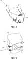
- face masks and other personal protective equipment such as surgical gowns, surgical drapes, bouffant caps, etc.
- PPE personal protective equipment
- face masks worn by healthcare providers help reduce infections in patients by filtering the air exhaled from the wearer thus reducing the number of harmful organisms or other contaminants released into the environment.
- face masks to prevent the spread of disease by filtering and containing any expelled germs. Additionally, face masks protect the healthcare worker by filtering airborne contaminants and microorganisms from the inhaled air.
- Some diseases can be spread through contact of infected blood or other body fluids to another person's mucous membranes (i.e., eyes, nose, mouth, etc.).
- the healthcare industry recommends specific practices to reduce the likelihood of contact with contaminated body fluids.
- One such practice is to use face masks, surgical gowns, surgical drapes, bouffant caps, and other similar PPE, which are resistant to penetration from a splash of body fluids.
- the material used to form such PPE can be comprised of several layers.
- the layer that is positioned closest to the skin of the wearer is typically referred to as the inner layer.
- the layer furthest from the skin of the wearer is referred to as the outer layer.
- An additional layer or layers of material can be disposed between the outer layer and the inner layer.
- one of these additional layers is a filtration layer, such as a microfiber fiberglass layer or an electret-treated meltblown layer.
- face masks, surgical gowns, surgical drapes, bouffant caps, and other similar PPE may be designed to be resistant to penetration by splashes of fluids so that pathogens found in blood or other fluids are not able to be transferred to skin of the user of such PPE.
- ASTM American Society of Testing and Materials
- the splash resistance of an article of PPE is typically a function of the ability of the layer or layers of the structure used in the article to resist fluid penetration, and/or their ability to reduce the transfer of the energy of the fluid splash to subsequent layers, and/or their ability to absorb the energy of the splash.
- Typical approaches to improving splash resistance are to use thicker materials or additional layers in the construction of the structure.
- US20050133036A1 discloses a face mask having baffle layer for improved fluid resistance.
- these solutions may increase the cost of the structure, increase the weight of the structure, reduce the porosity of the structure, and add discomfort to the wearer by negatively impacting the thermal resistance of the multi-layered structure.
- An additional approach to improving the splash resistance of materials or structures used to form face masks, surgical gowns, surgical drapes, bouffant caps, or other similar PPE is to incorporate a layer of porous, high loft, fibrous material.
- This type of material is advantageous in that the layer will absorb or dissipate the energy of the impact of the fluid splash.
- fluid will saturate this high loft material, hence reducing its effectiveness in absorbing the energy of a future fluid splash.
- fluid can be squeezed out of this high loft material and may be transferred through subsequent layers upon compression of the multi-layered structure. As such, a need exists for a structure and articles formed therefrom having improved splash resistance but without imparting discomfort to the user.
- the present invention provides for a splash resistant multi-layered structure.
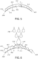
- the multi-layered structure includes an outer layer of material having an outer-facing surface and an inner-facing surface; an inner layer of material having an outer-facing surface and an inner-facing surface; and a first plurality of three-dimensional spacers disposed on a surface within the multi-layered structure.
- the plurality of three-dimensional spacers define a space between the outer layer of material and the inner layer of material, where the space spans a distance at least as great as a maximum height of the plurality of three-dimensional spacers, and the plurality of three-dimensional spacers aid in absorbing energy associated with a fluid contacting the outer layer of material.
- the first plurality of three-dimensional spacers comprises a binder, an ink, an adhesive, or a combination thereof. Further, the first plurality of three-dimensional spacers includes an encapsulated functional additive contained within the binder, the ink, the adhesive, or the combination thereof, where the functional additive comprises a phase change material.
- the first plurality of three-dimensional spacers define a first plurality of channels for redirecting the flow of fluid that strikes the outer layer of material, where the channels have an orientation such that the fluid is directed laterally away from the point of contact of the fluid through the channels.
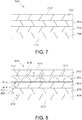
- the first plurality of three-dimensional spacers are arranged in a pattern.
- the pattern can be continuous or discontinuous.
- the pattern can include a plurality of dots, where the dots are arranged on a layer of material in a series of columns and a series of rows.
- the first plurality of three-dimensional spacers can include an acrylic binder or an elastic or non-elastic expandable ink.
- the functional additive can further comprise a fragrance, an absorbent material, a superabsorbent material, an antimicrobial, a therapeutic agent, a topical ointment, or a combination thereof.
- the functional additive can be present in an amount ranging from about 0.25 wt.% to about 70 wt.% based on the dry weight of the first plurality of three-dimensional spacers present within the multi-layered structure.
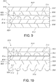
- the multi-layered structure can include an additional layer of material disposed between the outer layer of material and the inner layer of material.
- the first plurality of three-dimensional spacers can be disposed on an outer-facing surface of the additional layer of material.
- the additional layer of material can be a spunbond web positioned adjacent the outer layer of material, where the structure can further include a meltblown web, where the meltblown web can be positioned adjacent the inner layer of material.
- the multi-layered structure can include a second plurality of three-dimensional spacers, where the second plurality of three-dimensional spacers are disposed on an inner-facing surface of the inner layer of material, and where the first plurality of three-dimensional spacers can include an acrylic binder and the second plurality of three-dimensional spacers can include a phase change material encapsulated within an acrylic binder.
- the additional layer of a material is a meltblown web.
- the first plurality of three-dimensional spacers can be disposed on the inner-facing surface of the outer layer of material or the first plurality of three-dimensional spacers can be disposed on an inner-facing surface of the meltblown web.
- the multi-layered structure can include a second plurality of three-dimensional spacers, where the second plurality of three-dimensional spacers can disposed on an inner-facing surface of the inner layer of material, the first plurality of three-dimensional spacers can include an acrylic binder, and the second plurality of three-dimensional spacers can include a phase change material encapsulated within an acrylic binder.
- the outer layer of material and the inner layer of material can each include a spunbond web.
- the present invention contemplates an article such as a face mask, a surgical gown, a surgical drape, a surgical protective hood/headwear,or a bouffant cap formed from the multi-layered structure described above.
- the present invention is directed to a splash resistant multi-layered structure.
- the splash resistance of the multi-layered structure is facilitated by a state of forced separation between adjacent layers of the multi-layered structure, such as between an inner-facing surface (i.e., a layer that faces towards the skin of a user) of a first layer of material and an outer-facing surface (i.e., a layer that faces away from the skin of a user) of a second layer of material.
- the forced separation between the two adjacent layers of material is the result of the presence of a plurality of three-dimensional spacers positioned between the adjacent layers of the multi-layered structure, where the plurality of three-dimensional spacers can be positioned on one or both of the adjacent layers of the multi-layered structure such that a distance at least as large as the maximum height of the plurality of three-dimensional spacers separates the two layers from each other.
- the three-dimensional spacers can be present on a layer of material in a continuous or discontinuous pattern or can be present on a layer of material in a random fashion.
- a plurality of channels can be formed between the layers to increase the interlayer spacing so that the splash resistance and fluid barrier capabilities of the multi-layered structure can be enhanced by facilitating the lateral spread of fluid once the fluid contacts the multi-layered structure.
- the stiffness provided by the three-dimensional spacers can facilitate the lateral dissipation of energy to prevent compression of the layers of the multi-layered structure when a fluid insult occurs. Such an arrangement prevents fluid from penetrating through the entire multi-layered structure, which could endanger the health of the user when the multi-layered structure is formed into PPE.
- the presence of the three-dimensional spacers can reduce the number of layers of material required to form a multi-layered structure having sufficient splash resistance.
- the presence of the three-dimensional spacers can enable the use of materials with lower basis weights to form a PPE article, which can increase the comfort of the user.
- the reduction in basis weight or elimination of one or more layers of material can reduce thermal resistance, lower the pressure drop across the layers of the multi-layered structure, and reduce the overall weight of the multi-layered structure to enhance breathability and comfort.
- the filter material component or filtration layer of the multi-layered structure may be modified to take advantage of the splash resistance and fluid barrier capabilities of the multi-layered structure.
- Meltblown fabrics (and/or other filtration media) used in conventional multi-layered structures for articles such as face masks are selected to provide greater resistance to penetration by liquids as part of the multi-layered structure.
- the meltblown fabrics (and/or other filtration media) may have unnecessarily high basis weights and/or unnecessarily high levels of pressure drop.
- the advantageous splash resistance and fluid barrier capabilities of the multi-layered structure enable use of meltblown fabrics (and/or other filtration media) having lower basis weights and/or lower levels of pressure drop.
- the greater "breathability" of the meltblown fabrics (and/or other filtration media) provides more efficient energy transfer between phase change material and air exchanged during a respiration cycle. This is believed to be significant at least because it allows for the economical and efficient use of phase change material in an article such as a face mask. As a result, less phase change material may be needed to accomplish a threshold level of energy transfer, which important because it reduces the amount of an expensive component in a disposable article and can have a very large impact on the commercial viability of such disposable articles.
- the modification is also significant because it enables the manufacture of practical and economical face masks having a smaller face mask area while maintaining or even increasing filtration efficiency, protection, and/or user comfort. As a result of using less or fewer materials and/or decreasing mask size, one can reduce the cost of a disposable article which can have a very large impact on the commercial viability of such disposable articles.
- Figs. 1 and 2 show a face mask 100 which may be formed from the multi-layered splash resistant structure contemplated by the present invention.
- the face mask 100 includes a body portion 102 that is configured to be placed over the mouth and at least part of the nose of the user 108 such that the air exchanged through normal respiration passes through the body portion 102 of the face mask 100.
- the body portion 102 can be of a variety of styles and geometries, such as, but not limited to, flat half mask, pleated face masks, cone masks, flat folded personal respiratory devices, duckbill style mask, trapezoidally shaped masks, etc.
- the body portion 102 may be configured to have one or more horizontal pleats, one or more vertical pleats, or no pleats, where such designs are generally known in the art.
- the face mask 100 therefore isolates the mouth and the nose of the user 108 from the environment.
- the face mask 100 is attached to the user 108 by a pair of tie straps 104 which are wrapped around the head of the user 108 (and a hair cap 106 if worn by the user) and are connected to one another. It is to be understood, however, that other types of fastening arrangements may be employed in accordance with various exemplary embodiments of the present invention.
- the face mask 100 may be attached to the user 108 by ear loops, elastic bands wrapping around the head, or a hook and loop type fastener arrangement, or the face mask 100 may be wrapped as a single piece around the head of the user 108 by an elastic band.
- the face mask 100 may also be directly attached to the hair cap 106.
- the configuration of the face mask 100 may be different in accordance with various exemplary embodiments.
- the face mask 100 may be made such that it covers both the eyes, hair, nose, throat, and mouth of the user.
- the present invention is not limited to only face masks 100 that cover only the nose and mouth of the user 108.
- Fig. 3 shows a front view of a surgical gown 200 that can be formed from the splash resistant multi-layered structure contemplated by the present invention.
- the gown 200 can include a collar 202, cuffs 204, and shoulder seams 206 that link the sleeves 208 to the main body 210.
- Other exemplary articles that can be formed from the splash resistant multi-layered structure of the present invention include surgical drapes or any other PPE in which splash resistant characteristics are desired.
- the multiple layers of material in the multi-layered structure used to form the aforementioned face masks, surgical gowns, drapes, surgical protective hoods/headwear, bouffant caps, etc. contemplated by the present invention may be joined by various methods, including adhesive bonding, thermal point bonding, or ultrasonic bonding.
- the multi-layered splash resistant structure of the present invention includes a plurality of three-dimensional spacers that are disposed on one or more outer-facing surfaces (i.e., surfaces facing away from the skin of the user) or inner-facing surfaces (i.e., surfaces facing towards the skin of the user) of the multi-layered structure.
- the plurality of three-dimensional spacers is formed from a composition that includes a binder, an ink, a polymer, or a combination thereof.
- binders can be obtained from Lubrizol or H.B. Fuller.
- the binders can be water soluble.
- such binders, inks, adhesives, etc. can be hydrophobic, where the hydrophobicity of the binder, ink, adhesive, etc. can the enhance splash resistance by preventing fluid from penetrating subsequent layers of the article.
- the three-dimensional spacers can be formed from heat-activatable expandable inks, such as AQUAPUFFTM inks obtainable from Polytex Environmental Inks (Bronx, NY).
- AQUAPUFFTM inks obtainable from Polytex Environmental Inks (Bronx, NY).
- Other commercially available inks are available from Eastern Color and Chemical Company (Greenville, SC), International Coatings Company (Cerritos, CA), Dongguan City Haiya Printing Material Company (China), Atlas Screen Supply Company (Schiller Park, IL), NEHOC Australia Pty, Limited (Australia), and INX International Ink Corporation (Schaumburg, IL).
- Such inks are expandable inks which react when exposed to heat to produce a reaction that causes the ink to expand or "puff" into a three-dimensional structure.
- the inks may include additives, known in the art as blowing agents, and can include chemicals which undergo physical or chemical changes on heating to form a gaseous product.
- additives include EXPANCELTM 461 DU Microsphere (supplied by Expancel), Unicell OH (supplied by OMYA), Genitron LE (supplied by Acrol), or other gas-encapsulated thermoplastic microspheres.
- the printing of such inks onto one or more layers of the multi-layered structure of the present invention can occur at a number of steps in the process, such as in an off-line printing step, or on-line during the article assembly process. Further, the ink can be printed at one process step, and expanded by heat activation in a later, downstream step.
- the three-dimensional spacers can include an optional amount of moisture absorbing polymer.
- the polymer can be present in the three-dimensional structures spacers in an amount as desired.
- the three-dimensional spacers can contain up to about 1 wt.%, such as up to about 5 wt.%, or even up to about 10 wt.% or more of a moisture absorbing polymer.
- suitable moisture absorbing polymers include, but are not limited to, polyethylene oxide, polyethylene glycol, polyvinyl alcohol, polyvinyl pyrrolidones, polyvinyl pyridine, or a combination thereof.
- the three-dimensional spacers can include an optional elastomeric polymer.
- the elastomeric polymer can make the foam structure resilient and can help with moisture absorbency by trapping water like a sponge. Further, the elastomeric polymer may add resilience or flexibility to the three-dimensional spacers.
- the elastomeric polymer component can be present in an amount which is effective to achieve the desired dimensional change properties.
- the three-dimensional spacers can contain up to about 1 wt.%, such as up to about 5 wt.%, or even up to about 10 wt.% or more of an elastomeric polymer to provide improved properties.
- elastomeric polymers include, but are not limited to, thermoplastic polyurethanes, olefinic elastomeric polymers (Vistamaxx®), poly(ether-amide) block copolymers, thermoplastic rubbers such as uncrosslinked polyolefins, styrene-butadiene copolymers, silicon rubbers, synthetic rubbers such as nitrile rubber, styrene isoprene copolymers, styrene ethylene butylenes copolymers, butyl rubber, nylon copolymers, spandex fibers comprising segmented polyurethane, ethylene-vinyl acetate copolymer or a combination thereof.
- thermoplastic polyurethanes olefinic elastomeric polymers (Vistamaxx®), poly(ether-amide) block copolymers
- thermoplastic rubbers such as uncrosslinked polyolefins, styrene-butadiene copolymers,
- adhesion promoters can be added to the three-dimensional spacers.
- Carboset 514H available commercially from Noveon, Inc. of Cleveland, Ohio, is an acrylic colloidal dispersion polymer supplied in ammonia water, which can dry to a clear, water-resistant, non-tacky thermoplastic film.
- adhesion promotes facilitate the attachment of the three-dimensional spacers to the layer of material on which they are applied.
- the three-dimensional spacers can contain a coloring agent (e.g., pigment or dye), a solvent, and any other desired ingredients.
- a coloring agent e.g., pigment or dye
- a pigment refers to a colorant based on inorganic or organic particles which do not dissolve in water or solvents. Usually pigments form an emulsion or a suspension in water.
- a dye generally refers to a colorant that is soluble in water or solvents.
- the pigment or dye can be present in the three-dimensional spacers in an amount ranging from about 0.25 wt.% to about 40 wt.%, such as from about 0.5 wt. % to about 30 wt. %, such as from about 1 wt. % to about 20 wt. % on a dry weight basis after the spacers have formed to the layer of material on which they have been applied.
- Suitable organic pigments include dairylide yellow AAOT (for example, Pigment Yellow 14 Cl No. 21 095), dairylide yellow AAOA (for example, Pigment Yellow 12 Cl No. 21090), Hansa Yellow, Cl Pigment Yellow 74, Phthalocyanine Blue (for example, Pigment Blue 15), lithol red (for example, Pigment Red 52:1 Cl No. 15860:1), toluidine red (for example, Pigment Red 22 Cl No. 12315), dioxazine violet (for example, Pigment Violet 23 Cl No. 51319), phthalocyanine green (for example, Pigment Green 7 Cl No. 74260), phthalocyanine blue (for example, Pigment Blue 15 Cl No.
- dairylide yellow AAOT for example, Pigment Yellow 14 Cl No. 21 095
- dairylide yellow AAOA for example, Pigment Yellow 12 Cl No. 21090
- Hansa Yellow Cl Pigment Yellow 74
- Phthalocyanine Blue for example, Pigment Blue 15
- lithol red for
- Suitable inorganic pigments include titanium dioxide (for example, Pigment White 6 Cl No. 77891), carbon black (for example, Pigment Black 7 Cl No. 77266), iron oxides (for example, red, yellow, and brown), ferric oxide black (for example, Pigment Black 11 Cl No. 77499), chromium oxide (for example, green), ferric ammonium ferrocyanide (for example, blue), and the like.
- Suitable dyes include, for instance, acid dyes, and sulfonated dyes including direct dyes.
- Other suitable dyes include azo dyes (e.g., Solvent Yellow 14, Dispersed Yellow 23, and Metanil Yellow), anthraquinone dyes (e.g., Solvent Red 111, Dispersed Violet 1, Solvent Blue 56, and Solvent Orange 3), xanthene dyes (e.g., Solvent Green 4, Acid Red 52, Basic Red 1, and Solvent Orange 63), azine dyes (e.g., Jet Black), and the like.
- azo dyes e.g., Solvent Yellow 14, Dispersed Yellow 23, and Metanil Yellow
- anthraquinone dyes e.g., Solvent Red 111, Dispersed Violet 1, Solvent Blue 56, and Solvent Orange 3
- xanthene dyes e.g., Solvent Green 4, Acid Red 52, Basic Red 1, and Solvent Orange 63
- azine dyes e.g
- the three-dimensional spacers can be applied to an outer-facing surface or an inner-facing surface of any layer of material present in the multi-layered splash resistant structure of the present invention.
- the ink, binder, or polymer composition is generally dispersed or dissolved in water or another low viscosity carrier.
- exemplary solvents that can be used may include aliphatic hydrocarbons with common binder types, such as polyamide, shellac, nitro-cellulose, and styrene-maleic.
- solvent-based treatments include non-catalytic, block urethane resin, which generally demonstrate superior durability over traditional flexographic binders, such as styrene-maleic, rosin-maleic, and acrylic solutions.
- Desired solvent blends include various acetates such as ethyl acetate, N-propyl acetate, isopropyl acetate, isobutyl acetate, N-butyl acetate, and blends thereof; various alcohols including ethyl alcohol, isopropyl alcohol, normal propyl alcohol, and blends thereof; and glycol ethers including EKTASOLVETM, EP (ethylene glycol monopropyl ether), EB (ethylene glycol monobutyl ether), DM (diethylene glycol monomethyl ether), DP (diethylene glycol monopropyl ether), and PM (propylene glycol monomethyl ether), which may be obtained from Eastman Chemical of Kingsport, Tenn.
- glycols that may also be used are DOWANOLTM obtainable from Dow Chemical of Midland, Mich.
- a desired solvent blend may be a blend of about 50% to about 75% glycol ether, about 25% to about 35% N-propyl acetate, and about 15% to about 25% N-butyl acetate.
- Suitable water-based three-dimensional spacers may further include emulsions that may be stabilized in water-ammonia and may further comprise alcohols, glycols, or glycol ethers as co-solvents.
- organic solvents (less than or equal to about 7 wt.%) may be added to water-based treatments: alcohols, for example, propan-2-ol may be added for speeding up drying and assisting wetting, glycols, for example, mono propylene glycol to slow down drying, glycol ethers, for example, dipropyl glycol mono methyl ether to aid film formation.
- solvents may be commodity chemicals, commercially available from various companies.
- water-based treatments include self-crosslinking acrylic copolymer emulsion, which may have demonstrated superior durability over traditional non-crosslinking binders such as acrylic solutions and dispersion copolymers.
- the heat-activatable expandable treatment may comprise a binder.
- the binder helps stabilize the composition used to form the three-dimensional spacers onto the layer of material to which it is being applied.
- one or more encapsulated functional additives can be combined within one of the binders, adhesives, or inks discussed above and then applied to one or more layers of the multi-layered structure of the present invention to provide an added benefit to the user of the multi-layered structure.
- the functional additive can be released from its encapsulant upon crushing of the microencapsulated functional additive, which could occur when the article of the present invention is opened from its packaging, unfolded, etc. or when the article of the present invention is wetted with a fluid.
- the plurality of three-dimensional spacers include a phase change material (PCM) to provide for cooling, and may further include antimicrobial agent to provide antimicrobial protection, a fragrance for odor control, a topical ointment for skincare, a therapeutic agent to provide a specific treatment, an absorbent material such as activated carbon for moisture or odor control, a superabsorbent material, or any other additive that could be useful in an article used as PPE.
- PCM phase change material
- a fragrance can be encapsulated into microcapsules that are then incorporated into a binder to form the three-dimensional spacers of the present invention, and when an article containing the three-dimensional spacers is wetted, the fragrance could be released due to "crushing" or "disintegration" of the microcapsules containing the fragrance in order to mask an odor or release a scent, perhaps as an indicator of the article or layer of material being splashed.
- a superabsorbent material can be incorporated into a binder to form the three-dimensional spacers of the present invention, and when an article containing the three-dimensional spacers is wetted, the superabsorbent material could be activated in order to help contain the a fluid insult.
- the functional additives can be encapsulated in such a way to provide functional permanency over longer time or to provide time-release of the functionalities mentioned above over different frequencies of time.
- Such additives can be present in the three-dimensional spacers in an amount ranging from about 0.25 wt.% to about 70 wt.%, such as from about 0.5 wt.% to about 60 wt.%, such as from about 1 wt.% to about 50 wt.% on a dry weight basis after the spacers have formed to the layer of material on which they have been applied.
- the specific composition of the plurality of three-dimensional spacers, the three-dimensional spacers can be applied to one or more layers of material of the multi-layered structure of the present invention in any suitable pattern or in a random fashion. If the three-dimensional spacers are applied in a pattern, the pattern can be continuous or discontinuous.
- the three-dimensional spacers 302 can be applied to a layer of the multi-layered structure 300 in the form of a series dots having a semi-circular shape and a maximum height S, where the dots are arranged in a series of offset columns 304 and a series of offset rows 306 to form channels 314 therebetween.
- the three-dimensional spacers can be in the form of lines, crosses, gridlines, logos, or any other form or shape and can have any density, height, or texture so long as the three-dimensional spacers provide for sufficient spacing between the layers of material used to form the multi-layered structure of the present invention so that the splash resistant properties of the multi-layered structure can be achieved.
- the particular dimensions, shape, and spacing of the three-dimensional spacers is a function of the materials being used.
- the three-dimensional spacers can have various textures.
- the three-dimensional spacers can be "puffy” or malleable (e.g., soft and cushiony), which can impart improved pressure distribution capabilities to the multi-layered structure incorporating the three-dimensional spacers, such as when the multi-layered structure is used in a face mask, or the three-dimensional spacers can have a rigid texture to provide the multi-layered structure with structural stability and prevent compression of the multi-layered structure when a fluid insult occurs.
- the three-dimensional spacers can be present on from about 5% to about 100%, such as from about 10% to about 99.5%, such as from about 15% to about 99% of the surface area of the layer of material on which the three-dimensional spacers are applied. Further, the three-dimensional spacers can be applied to a layer of material in a composition that also includes a binder or carrier using any known method such as a gravure roll, slot coating, continuous spraying, discontinuous spraying, screen printing, ink jet printing, etc.
- heat can be applied after a composition containing the three-dimensional spacers has been applied to a layer of material to activate the plurality of three-dimensional characteristics of the spacers present on the layer of material, such as when the three-dimensional spacers are in the form of a "puffable" ink.
- the three-dimensional spacers can be in the form of dots, grids, logos, crosses, etc. which can have a width, length, or diameter of from about 0.25 mm to about 5 mm and can have a height S ranging from about 0.025 mm to about 3 mm. Further, the three-dimensional spacers can be hard, soft, or foam-like as needed by the application.
- the three-dimensional spacers can be applied to the various layers of the multi-layered structure in an amount ranging from about 1 % to about 70% of the total surface area of the surface to which the spacers are applied for breathable barrier or porous materials and in an amount ranging from about 1% to about 100% of the total surface area of the surface to which the spacers are applied for non-porous/non-breathable materials.
- the plurality of three-dimensional spacers discussed above can be applied to one or more layers of material in the multi-layered structure contemplated by the present invention.
- the layers of the multi-layered structure can be formed from one or more non-woven materials (e.g., a spunbond, meltblown, SMS laminate, spunlace, hydroentangled, carded, elastomeric, or foam webs), one or more films, or any combination thereof, and the three-dimensional spacers can be present on any one of the aforementioned layers of material, where the spacers can be present on the layer of material's outer-facing surface, inner-facing surface, or both.
- non-woven materials e.g., a spunbond, meltblown, SMS laminate, spunlace, hydroentangled, carded, elastomeric, or foam webs
- the three-dimensional spacers can be present on any one of the aforementioned layers of material, where the spacers can be present on the layer of material's outer-facing surface, inner-facing surface, or both.
- the splash resistance as measured by ASTM F1862-13, can be further enhanced if the materials in the multi-layered structure are hydrophobic, either naturally or through additives or treatments. This can reduce the potential for wicking of the fluid insult through the layers.
- the three-dimensional spacers can be present on more than one of the layers of material in the multi-layered structure of the present invention.
- the various layers of material used to form the multi-layered structure can each have basis weights ranging from about10 gsm to about 150 gsm, such as from about 12.5 gsm to about 100 gsm, such as from about 15 gsm to about 80 gsm.
- any meltblown material layers can have a basis weight ranging from about 10 gsm to about 75 gsm, such as from about 12.5 gsm to about 70 gsm, such as from about 15 gsm to about 50 gsm.
- any spunlace or bicomponent nonwoven material layers can have a basis weight ranging from about 10 gsm to about 25 gsm, such as from about 12.5 gsm to about 20 gsm, such as from about 15 gsm to about 17.5 gsm.
- any spunbond material layers can have a basis weight ranging from about 15 gsm to about 60 gsm, such as from about 20 gsm to about 50 gsm, such as from about 20 gsm to about 45 gsm.
- a spunbond web is one type of nonwoven material that can be used in one or more layers of the multi-layered structure of the present invention.
- a spunbond web is a material made from small diameter fibers which are formed by extruding molten thermoplastic material as filaments from a plurality of fine, usually circular capillaries of a spinneret with the diameter of the extruded filaments then being rapidly reduced as by, for example, in U.S. Pat. Nos. 4,340,563 ; 3,692,618 ; 3,802,817 ; 3,338,992 ; 3,341,394 ; 3,502,763 ; and 3,542,615 .
- Spunbond fibers are generally not tacky when they are deposited onto a collecting surface.
- Spunbond fibers are generally continuous and have average diameters (from a sample of at least 10) larger than 7 microns, more particularly, between about 10 and 20 microns.
- a meltblown web can also be used in one or more layers of the multi-layered structure of the present invention.
- a meltblown web is formed by extruding a molten thermoplastic material through a plurality of fine, usually circular, die capillaries as molten threads or filaments into converging high velocity, usually hot, gas (e.g. air) streams which attenuate the filaments of molten thermoplastic material to reduce their diameter, which may be to microfiber diameter.
- the meltblown fibers are then carried by the high velocity gas stream and are deposited on a collecting surface to form a web of randomly dispersed meltblown fibers.
- Such a process is disclosed, for example, in U.S. Pat. No. 3,849,241 .
- Meltblown fibers are microfibers which may be continuous or discontinuous, are generally smaller than 10 microns in average diameter, and are generally tacky when deposited onto a collecting surface.
- a laminate of spunbond and meltblown material can also be used in one or more layers of the multi-layered structure of the present invention.
- a laminate and others are described in U.S. Pat. Nos. 4,041,203 ; 5,169,706 ; 5,145,727 ; 5,178,931 ; and 5,188,885 .
- Such a laminate may be made by sequentially depositing onto a moving forming belt first a spunbond layer, then a meltblown layer and last another spunbond layer and then bonding the laminate in a manner described below.
- the layers may be made individually, collected in rolls, and combined in a separate bonding step.
- Multilayer laminates usually have a basis weight of from about 0.1 to 12 osy (6 to 400 gsm), or more particularly from about 0.75 to about 3 osy.
- Multilayer laminates may also have various numbers of meltblown (abbreviated as "M”) layers or multiple spunbond (abbreviated as “S”) layers in many different configurations and may include other materials like films (abbreviated as "F”) or coform materials (see U.S. Pat. No. 4,100,324 for descriptions of exemplary coform materials). Examples include SMMS laminates, SM laminates, SFS laminates, etc.
- a hydroentangled web can also be used in one or more layers of the multi-layered structure of the present invention.
- Hydroentangled webs can also be used in one or more layers of the multi-layered structure of the present invention.
- a hydroentangled web is a web formed by a process wherein a nonwoven web, or layers of a non-woven web, are subjected to streams of a non-compressible fluid, e.g., water, at a high enough energy level and for a sufficient time to entangle the fibers thereof.
- the fluid may advantageously be used at a pressure of between about 200 and 5000 psig (14-351 kg/cm 2 gauge) from a distance of a few inches (centimeters) above the web while the web is supported by a mesh structure. This process is described in detail in U.S. Pat. No. 3,486,168 .
- Nonwoven webs subjected to hydroentangling are referred to as, for example, spunlace materials.
- a bonded carded web can also be used in one or more layers of the multi-layered structure of the present invention.
- a bonded carded web is a nonwoven web that is made from staple fibers which are sent through a combing or carding unit, which separates or breaks apart and aligns the staple fibers in the machine direction to form a generally machine direction-oriented fibrous nonwoven web. This material may be bonded together by methods that include point bonding, through air bonding, ultrasonic bonding, adhesive bonding, etc.
- An airlaid web can also be used in one or more layers of the multi-layered structure of the present invention.
- An airlaid web is a nonwoven web formed by a process in which a fibrous nonwoven layer can be formed. In the airlaying process, bundles of small fibers having typical lengths ranging from about 3 to about 52 millimeters (mm) are separated and entrained in an air supply and then deposited onto a forming screen, usually with the assistance of a vacuum supply. The randomly deposited fibers then are bonded to one another using, for example, hot air or a spray adhesive. Airlaying is taught in, for example, U.S. Pat. No. 4,640,810 .
- the multi-layered structures of the present invention can also include one more layers of thin, breathable films that are commonly made from thermoplastic polyolefins like polyethylene and polypropylene and copolymers thereof because of their relatively low cost and ability to be processed.
- Polyethylene is generally used in the film production and when used in articles such as gowns or drapes, the film can be commonly "filled” with calcium carbonate, various kinds of clay, silica, alumina, barium carbonate, sodium carbonate, magnesium carbonate, talc, barium sulfate, magnesium sulfate, aluminum sulfate, titanium dioxide, zeolites, cellulose-type powders, kaolin, mica, carbon, calcium oxide, magnesium oxide, aluminum hydroxide, pulp powder, wood powder, cellulose derivatives, chitin and chitin derivatives, to increase breathability, while when used in articles such as masks, the film should be perforated or apertured to allow for the passage of air.
- the present invention provides for a multi-layered structure which incorporates a layer of material having a pattern or random distribution of three-dimensional spacers applied thereon.
- Such a layer improves the ability of the multi-layered structure to resist penetration by a splash of fluid by reducing the contact of adjacent layers of material and/or absorbing the energy produced by a fluid impact on the multi-layered structure, and/or providing for a mechanism by which fluid that strikes the multi-layered structure may be channeled away from the point of contact.
- one or more of the layers of the multi-layered structure can be formed from a high opacity hydrophobic material.
- the use of such a material can further enhance the ability of the multi-layered structure to prevent fluids from passing through the inner layer and can help avoid the potential false positives (failures) in the ASTM F1862-13 test, which can happen with thin or translucent materials are used for the inner layer of the multi-layered structure.
- thin or translucent materials are used and the blood breaches the layer of material that is adjacent the inner layer, it can appear that all layers of the structure have been breached resulting in a failure per the ASTM F1862-13 method, even when a breach of the inner layer has not actually occurred.
- the multi-layered structure can be formed into various articles of personal protective equipment including, but not limited to, face masks, surgical gowns, surgical drapes, surgical protective hoods/headwear, bouffant caps, and the like as discussed above.
- the three-dimensional spacers and layers of material discussed above can be arranged in various embodiments to form a multi-layered structure that improves splash resistance and can be employed in face masks, surgical gowns, surgical drapes, bouffant caps, and other PPE, where the forced separation of layers facilitated by the plurality of three-dimensional spacers enhances the splash resistance of the structure without the adding bulk, weight, and discomfort that occur when splash resistance is increased via the use of additional layers of material.
- Figs. 5 and 6 two layers of a multi-layered structure of the present invention are shown to demonstrate the functionality of the three-dimensional spacers when a fluid insult such is introduced to the multi-layered structure.
- Fig. 5 is a cross-sectional view of a multi-layered structure that includes an inner layer of material 300 and an outer layer of material 400 prior to an insult of a bodily fluid 308, such as blood, where the inner layer of material 300 is the layer closest to the skin of a user and the outer layer of material 400 is the layer furthest from the user when the structure is part of PPE such as a face mask, surgical gown, surgical drape, bouffant cap, etc.
- the inner layer of material 300 includes an outer-facing surface 310 and an inner-facing surface 312, while the outer layer of material 400 includes an outer-facing surface 402 and an inner-facing surface 404.
- a plurality of three-dimensional spacers 302 are disposed on the outer-facing surface 310 of the inner layer of material 300, and the three-dimensional spacers 302 have a maximum height S.
- the distance D between the outer-facing surface 310 of the inner layer of material 300 and the inner-facing surface 404 of the outer layer of material 400 is at least as large as the maximum height S, where the maximum height S of the three-dimensional spacers 302 forces separation between the inner layer of material 300 and the outer layer of material 400.
- Such an arrangement enhances the fluid barrier and splash resistance of the multi-layered structure of the present invention.
- the separation between the layers helps to reduce the area of contact between the layers and thus lowers the ability of fluid to transfer from one layer to the next.
- the three-dimensional spacers 302 therefore help to separate the layers of material 300 and 400 such that fluid cannot be as easily transferred through the layers by decreasing the area of surface contact between the layers.
- the three-dimensional spacers 302 define channels 314 that are located adjacent the a surface of a layer of material on which the three-dimensional spacers 302 are disposed, which happens to be the outer-facing surface 310 of the inner layer 300 in the particular multi-layered structure of Fig. 5 , although it is to be understood that the three-dimensional spacers 302 and channels 314 can be present on an inner or outer-facing surface of any layer.
- a fluid insult may be transferred and more uniformly distributed across a layer when the layer is contacted with the fluid insult. This separation also provides for a contained space in which the fluid can easily flow laterally when the layers are compressed, which also helps prevent the fluid from transferring through the layers.
- the channels 314 may be interconnected channels such that all of the channels 314 are in communication with one another. This allows for the advantage of having fluid which contacts a layer at any point of contact 318 to be distributed through a larger number of channels 314. Alternatively, the channels 314 may be configured such that only a portion of the channels 314 are in communication with one another.
- the channels 314 may be provided in any number in accordance with other exemplary embodiments of the present invention.
- the channels 314 may thus redirect fluid which contacts a layer to a desired location.
- the channels 314 may be configured such that fluid which engages a layer of material at the point of contact 318 is redirected along the outer surface that layer and flows through the multi-layered structure to a position along, for instance, the edge of the multi-layered structure.
- Fig. 6 shows the functionality of the three-dimensional spacers 302 and channels 314 during an insult of a bodily fluid 308.
- the three-dimensional spacers 302 are configured such that their three-dimensional structure enables the outer layer of material 400 to flex and absorb at least a portion of the forces transmitted by the fluid 308 striking the outer-facing surface 402 of the outer layer of material 400 without allowing the inner-facing surface 404 to contact the outer-facing surface 310 of the inner layer of material 300.
- the presence of the three-dimensional spacers 302 having a maximum height S results in the space between the inner-facing surface 404 of the outer layer of material 400 and the outer-facing surface 310 of the inner layer of material 300 having a distance D that is at least as large as the maximum height S.
- Absorption of the aforementioned forces imparted by a fluid strike may help to prevent fluid from penetrating past the inner layer of material 300 of the multi-layered structure of the present invention.
- fluid may be the case that fluid is already trapped between one or more layers of the multi-layered structure of the present invention. Forces imparted by the fluid 308 striking the multi-layered structure cause these already trapped fluids to be pushed further through the multi-layered structure.
- the various multi-layered structures contemplated by the present invention and shown in Figs. 8-12 may be composed of two or more of layers 802, 804, 806, and 808.
- the arrangement of the layers 802, 804, 806, and 808 may be modified such that any combination of sequencing is possible and such that anywhere from two to four layers can be utilized, where the four-layered structures 800, 860, and 870, and the three-layered structures 880 and 890 represent some of the particular embodiments contemplated by the present invention.
- the outer layer 802, middle layers 804 and 806, and the inner layer 808 may be made of the same materials or different materials.
- a plurality of three-dimensional spacers can be applied to the inner-facing surface, the outer-facing surface, or both of any of the layers of material 802, 804, 806, and 808.
- additional layers other than those shown in the figures may also be incorporated into the multi-layered structure to achieve the desired properties, although the present inventors have found that sufficient splash resistance can be achieved with the use of fewer layers than taught in the art, which is due, at least in part, to the incorporation of the three-dimensional spacers 302 into the various multi-layered structures 800, 860, 870, 880, and 890.
- the additional layers may be constructed from various materials known to those skilled in the art such as those described above.
- multi-layered structure construction contemplates any other suitable arrangement of multiple layers of material where a plurality of three-dimensional spacers are applied to one or both surfaces of any of the multiple layers of material.
- the multi-layered structure 800 has four layers including an outer layer of material 802 and an inner layer of material 808, where the outer layer of material 802 includes an outer-facing surface 810 and an inner-facing surface 818, and the inner layer of material 808 includes an outer-facing surface 824 and an inner-facing surface 812. Disposed between the outer layer of material 802 and the inner layer of material 808 are a layer of material 804 and a layer of material 806. The layer of material 804 is positioned adjacent the outer layer of material 802 and includes an outer-facing surface 814 and an inner-facing surface 816.
- the layer of material 806 is positioned adjacent the inner layer of material 808 and includes an outer-facing surface 820 and an inner-facing surface 822.
- a plurality of three-dimensional spacers 302 are disposed on the outer-facing surface 814 of the layer of material 804, which, in this particular embodiment, can also be referred to as the second layer of material present past the outer-facing surface 810 of the outer layer of material 802, which also serves as the outer-facing surface of the entire multi-layered structure.
- the plurality of three-dimensional spacers 302 define a plurality of channels 314 that are formed between the outer layer of material 802 and the layer of material 804.
- the plurality of three-dimensional spacers 302 create a forced separation or space between the outer-facing surface 814 of the second layer of material 804 and the inner-facing surface 818 of the first (or outermost) layer of material 802.
- the separation between the outer-facing surface 814 of the second layer of material 804 and the inner-facing surface 818 of the first layer of material 802 spans a distance D, which is controlled at least in part by the maximum height S of the three-dimensional spacers 302.
- the outer (first) layer of material 802, the second layer of material 804 on which the three-dimensional spacers 302 are disposed, and the inner (fourth) layer of material 808 are spunbond webs, while the third layer of material 806 positioned adjacent the inner layer of material 808 is a meltblown web.
- the three-dimensional spacers 302 are formed from a binder which contains an encapsulated phase change material.
- the multi-layered structure 800 was tested for splash resistance according to ASTM Standard F-1862 (Level 3), where the fluid was prevented from passing through the three-dimensional spacers 302 present on the outer-facing surface 814 of the spunbond layer of material 804, which is the second layer past the point of fluid contact at the outer-facing surface 810 of the outer layer of material 802.
- the multi-layered structure 800 of Fig. 8 required only two layers of material (e.g., spunbond layer 802 and spunbond layer 804 having the three-dimensional spacers 302 present on its outer-facing surface 814) to prevent passage of fluid through the multi-layered structure.
- Fig. 9 shows another four-layered structure 860 according to another embodiment of the present invention.
- the multi-layered structure 860 has four layers including an outer layer of material 802 and an inner layer of material 808, where the outer layer of material 802 includes an outer-facing surface 810 and an inner-facing surface 818, and the inner layer of material 808 includes an outer-facing surface 824 and an inner-facing surface 812. Disposed between the outer layer of material 802 and the inner layer of material 808 are a layer of material 806 and a layer of material 804.
- the layer of material 806 is positioned adjacent the outer layer of material 802 and includes an outer-facing surface 820 and an inner-facing surface 822.
- the layer of material 804 is positioned adjacent the inner layer of material 808 and includes an outer-facing surface 814 and an inner-facing surface 816.
- a plurality of three-dimensional spacers 302 are disposed on the outer-facing surface 814 of the layer of material 804, which, in this particular embodiment, can also be referred to as the third layer of material present past the outer-facing surface 810 of the outer layer of material 802, which also serves as the outer-facing surface of the entire multi-layered structure.
- the plurality of three-dimensional spacers 302 define a plurality of channels 314 that are formed between the layer of material 806 and the layer of material 804.
- the plurality of three-dimensional spacers 302 create a forced separation or space between the outer-facing surface 814 of the third layer of material 804 and the inner-facing surface 822 of the second layer of material 806.
- the separation between the outer-facing surface 814 of the third layer of material 804 and the inner-facing surface 822 of the second layer of material 806 spans a distance D, which is controlled at least in part by the maximum height S of the three-dimensional spacers 302.
- the outer (first) layer of material 802, the third layer of material 804 on which the three-dimensional spacers 302 are disposed, and the inner (fourth) layer of material 808 are spunbond webs, while the second layer of material 806 positioned adjacent the outer layer of material 802 is a meltblown web.
- the three-dimensional spacers 302 are formed from a binder which contains an encapsulated phase change material.
- the multi-layered structure 860 was tested for splash resistance according to ASTM Standard F-1862 (Level 3), where the fluid did pass through the three-dimensional spacers 302 present on the outer-facing surface 814 of the spunbond layer of material 804, which in the specific multi-layered structure 860 is the third layer past the point of fluid contact at the outer-facing surface 810 of the outer layer of material 802.
- the fluid did not pass through the entire multi-layered structure.
- the multi-layered structure 860 of Fig. 9 required three layers of material (e.g., spunbond layer 802, meltblown layer 806, and spunbond layer 804 having the three-dimensional structures 302 present on its outer-facing surface 814) to prevent passage of fluid through the multi-layered structure.
- the three-dimensional spacers 302 provide better splash resistance when positioned immediately adjacent a spunbond layer or any layer other than a meltblown layer that catches a majority of the initial fluid insult.
- the present inventors hypothesize that this may be the case because the three-dimensional spacers are configured in such an arrangement have more room between the layers and can repel the initial pressure of the fluid insult, after which the layers exposed to the fluid insult are positioned closer to each other, resulting the fluid absorbing through the layers.
- Fig. 10 illustrates a four-layered structure 870 according to one more embodiment of the present invention.
- the multi-layered structure 870 has four layers including an outer layer of material 802 and an inner layer of material 808, where the outer layer of material 802 includes an outer-facing surface 810 and an inner-facing surface 818, and the inner layer of material 808 includes an outer-facing surface 824 and an inner-facing surface 812. Disposed between the outer layer of material 802 and the inner layer of material 808 are a layer of material 804 and a layer of material 806.
- the layer of material 804 is positioned adjacent the outer layer of material 802 and includes an outer-facing surface 814 and an inner-facing surface 816.
- the layer of material 806 is positioned adjacent the inner layer of material 808 and includes an outer-facing surface 820 and an inner-facing surface 822.
- a plurality of three-dimensional spacers 302 are disposed on the outer-facing surface 814 of the layer of material 804, which, in this particular embodiment, can also be referred to as the second layer of material present past the outer-facing surface 810 of the outer layer of material 802, which also serves as the outer-facing surface of the entire multi-layered structure.
- the plurality of three-dimensional spacers 302 define a plurality of channels 314 that are formed between the outer layer of material 802 and the layer of material 804. Further, the plurality of three-dimensional spacers 302 create a forced separation or space between the outer-facing surface 814 of the second layer of material 804 and the inner-facing surface 818 of the first (or outermost) layer of material 802.
- a plurality of three-dimensional spacers 302 are also disposed on the inner-facing surface 812 of the inner layer of material 808, where the three-dimensional spacers 302 also define a plurality of channels 314.
- the plurality of three-dimensional spacers 302 present on the inner-facing surface 812 of the inner layer of material 808 can create a forced separation between a user's skin and the inner layer of material 808 to provide for added comfort to the user since the multi-layered structure 870 only contacts the user at the three-dimensional spacers 302 rather than across the entire inner-facing surface 812 as in multi-layered structures 800 and 860.
- the separation is controlled at least in part by the maximum height S of the three-dimensional spacers 302.
- the outer (first) layer of material 802, the second layer of material 804 on which a plurality of three-dimensional spacers 302 are disposed, and the inner (fourth) layer of material 808 are spunbond webs, while the third layer of material 806 positioned adjacent the inner layer of material 808 is a meltblown web.
- the three-dimensional spacers 302 present on the outer-facing surface 814 of the second layer of material 804 are in the form of an acrylic binder, while the three-dimensional spacers 302 present on the inner-facing surface 812 of the inner layer 808 are formed from a binder which contains an encapsulated phase change material so that the three-dimensional spacers 302 present on the inner-facing surface 812 not only minimize the degree of contact between the multi-layered structure 870 and the user, but can also facilitate additional cooling to the user.
- the multi-layered structure 870 was tested for splash resistance according to ASTM Standard F-1862 (Level 3), where the fluid was prevented from passing through the three-dimensional spacers 302 present on the outer-facing surface 814 of the spunbond layer of material 804, which is the second layer past the point of fluid contact at the outer-facing surface 810 of the outer layer of material 802.
- the multi-layered structure 870 of Fig. 10 required only two layers of material (e.g., spunbond layer 802 and spunbond layer 804 having the three-dimensional spacers 302 present on its outer-facing surface 814) to prevent passage of fluid through the multi-layered structure.
- Fig. 11 shows a three-layered structure 880 according to an additional embodiment of the present invention in which the spunbond layer 804 has been eliminated.
- the multi-layered structure 880 has three layers including an outer (first) layer of material 802 and an inner (third) layer of material 808, where the outer (first) layer of material 802 includes an outer-facing surface 810 and an inner-facing surface 818, and the inner (third) layer of material 808 includes an outer-facing surface 824 and an inner-facing surface 812. Disposed between the outer (first) layer of material 802 and the inner (third) layer of material 808 is a second layer of material 806.
- the second layer of material 806 includes an outer-facing surface 820 and an inner-facing surface 822.
- a plurality of three-dimensional spacers 302 are disposed on the inner-facing surface 818 of the outer layer of material 802, which is also referred to as the first layer of material and the outer-facing surface of the entire multi-layered structure.
- the plurality of three-dimensional spacers 302 define a plurality of channels 314 that are formed between the outer (first) layer of material 802 and the second layer of material 806. Further, the plurality of three-dimensional spacers 302 create a forced separation or space between the inner-facing surface 818 of the outer (first) layer of material 802 and the outer-facing surface 820 of the second layer of material 806.
- a plurality of three-dimensional spacers 302 are also disposed on the inner-facing surface 812 of the inner (third) layer of material 808, where the three-dimensional structures 302 also define a plurality of channels 314.
- the plurality of three-dimensional spacers 302 present on the inner-facing surface 812 of the inner (third) layer of material 808 can create a forced separation between a user's skin and the inner (third) layer of material 808 to provide for added comfort to the user since the multi-layered structure 880 only contacts the user at the three-dimensional spacers 302 rather than across the entire inner-facing surface 812 as in the multi-layered structures 800 and 860.
- the separation is controlled at least in part by the maximum height S of the three-dimensional spacers 302.
- the three-dimensional spacers 302 present on the inner-facing surface 818 of the (outer) first layer of material 802 are in the form of an acrylic binder, while the three-dimensional spacers 302 present on the inner-facing surface 812 of the inner (third) layer 808 are formed from a binder which contains an encapsulated phase change material so that the three-dimensional spacers 302 present on the inner-facing surface 812 not only minimize the degree of contact between the multi-layered structure 880 and the user, but can also facilitate additional cooling to the user.
- the multi-layered structure 880 was tested for splash resistance according to ASTM Standard F-1862 (Level 3), where the fluid was prevented from passing through the meltblown (second) layer 806 due at least in part to the presence of three-dimensional spacers 302 present on the inner-facing surface 818 of the spunbond outer (first) layer of material 802, which corresponds with the outermost layer of the multi-layered structure 880.
- the multi-layered structure 880 of Fig. 11 required only two layers of material (e.g., spunbond layer 802 having the three-dimensional spacers 302 present on its inner-facing surface 818 and meltblown layer 808) to prevent passage of fluid through the multi-layered structure, even though the multi-layered structure 880 was only three-layered.
- Fig. 12 illustrates a three-layered structure 890 according to yet another embodiment of the present invention in which the spunbond layer 804 has been eliminated.
- the multi-layered structure 890 has three layers including an outer (first) layer of material 802 and an inner (third) layer of material 808, where the outer (first) layer of material 802 includes an outer-facing surface 810 and an inner-facing surface 818, and the inner (third) layer of material 808 includes an outer-facing surface 824 and an inner-facing surface 812. Disposed between the outer (first) layer of material 802 and the inner (third) layer of material 808 is a second layer of material 806.
- the layer of material 806 includes an outer-facing surface 820 and an inner-facing surface 822.
- a plurality of three-dimensional spacers 302 are disposed on the inner-facing surface 822 of the second layer of material 806.
- the plurality of three-dimensional spacers 302 define a plurality of channels 314 that are formed between the second layer of material 806 and the inner (third) layer of material 808. Further, the plurality of three-dimensional spacers 302 create a forced separation or space between the inner-facing surface 822 of the second layer of material 806 and the outer-facing surface 824 of the inner (third) layer of material 808.
- a plurality of three-dimensional spacers 302 are also disposed on the inner-facing surface 812 of the inner (third) layer of material 808, where the three-dimensional spacers 302 also define a plurality of channels 314.
- the plurality of three-dimensional spacers 302 present on the inner-facing surface 812 of the inner (third) layer of material 808 can create a forced separation between a user's skin and the inner (third) layer of material 808 to provide for added comfort to the user since the multi-layered structure 890 only contacts the user at the three-dimensional spacers 302 rather than across the entire inner-facing surface 812 as in the multi-layered structures 800 and 860.
- the separation is controlled at least in part by the maximum height S of the three-dimensional spacers 302.
- the outer (first) layer of material 802 and the inner (third) layer of material 808 are spunbond webs, while the second layer of material 806 positioned between them and on which a plurality of three-dimensional spacers 302 are disposed is a meltblown web. Further, in the specific embodiment of Fig.
- the three-dimensional spacers 302 present on the inner-facing surface 822 of the second layer of material 806 are in the form of an acrylic binder, while the three-dimensional spacers 302 present on the inner-facing surface 812 of the inner (third) layer 808 are formed from a binder which contains an encapsulated phase change material so that the three-dimensional spacers 302 present on the inner-facing surface 812 not only minimize the degree of contact between the multi-layered structure 890 and the user, but can also facilitate additional cooling to the user.
- the multi-layered structure 890 was tested for splash resistance according to ASTM Standard F-1862 (Level 3), where the fluid was prevented from passing through the meltblown (second) layer 806 due at least in part to the presence of three-dimensional spacers 302 present on the inner-facing surface 822 of the meltblown (second) layer of material 806.
- the splash resistance was not as good as that shown for the multi-layered structure 880.
- the multi-layered structure 890 of Fig. 12 still required only two layers of material (e.g., spunbond layer 802 and meltblown layer 806 having the three-dimensional spacers 302 present on its inner-facing surface 822) to prevent passage of fluid through the multi-layered structure, even though the multi-layered structure 890 was only three-layered.
- Fig. 7 shows a four-layered structure 700 that does not include the three-dimensional spacers of the multi-layered structures of the present invention.
- the multi-layered structure 700 has an outer layer of material 702 having an outer-facing surface 710 and an inner layer of material 708 having an inner-facing surface 712, where the outer layer of material 702 is positioned furthest from the user and the inner layer of material 708 is positioned closest to the user, such as next to the skin. Between the outer layer of material 702 and the inner layer of material 708 are two additional layers 704 and 706. The layer of material 704 is adjacent the outer layer of material 702, while the layer of material 706 is adjacent the inner layer of material 708.
- the outer layer of material 702, the inner layer of material 708, and the layer of material 704 adjacent the outer layer of material 702 can each be formed from a spunbond web, while the layer of material 706 adjacent the inner layer of material 708 can be a meltblown material.
- the layer of material 706 adjacent the inner layer of material 708 can be a meltblown material.
- any of the types of nonwoven web, foam, or film materials can be used to form such layers.
- the multi-layered structure700 was tested for splash resistance according to ASTM Standard F-1862 (Level 3), where the fluid was prevented from passing through the layer of material 706, which is the third layer past the point of fluid contact at the outer-facing surface 710 of the outer layer of material 702, meaning that the multi-layered structure 700 of Fig. 7 required three layers (e.g., two spunbond layers 702, 704 and a meltblown layer 706) to prevent passage of fluid through the multi-layered structure 700.
- the multi-layered structures of the present invention can prevent the passage of fluid therethrough utilizing only one layer of material and the three-dimensional spacers discussed above, particularly when the three-dimensional spacers are adjacent a spunbond layer in the direction of the outer-facing surface or point of fluid contact.
- comparing Figs. 8-12 with Fig. 7 shows that incorporating three-dimensional spacers on a layer of a three-layered structure or a four-layered structure can increase the splash resistance of such a structure so long as the three-dimensional spacers are postioned within the multi-layered structure (e.g., not on the outer-facing surface of the outer layer or the inner-facing surface of the inner layer).
- Example 1 a multi-layered structure generally corresponding to the arrangement shown in Fig. 9 (Control Sample) but without the three-dimensional spaces 302 was compared to a multi-layered structure arranged as shown in Fig. 9 (Test Sample) for their ability to achieve Level 3 performance, which is the most stringent level of testing in ASTM F2100-11, where a face mask must resist splashes of 2 milliliters of synthetic blood (available from Johnson, Moen & Co., 2505 Northridge Lane NE, Rochester, MN 55906) at 160 mmHg per the ASTM F1862-13 procedure.
- the control sample included the four-layered structure 860 except for the three-dimensional spacers 302.
- the control sample multi-layered structure had an outer layer of material 802 formed from a polyester pulp wetlaid material having a basis weight of 0.5 ounces per square yard (16.95 gsm) and having an outer-facing surface 810.
- the control sample multi-layered structure 860 also included an inner layer of material 808 formed from a bicomponent carded nonwoven material having a basis weight of 0.5 ounces per square yard (16.95 gsm) and having an inner-facing surface 812, where the outer layer of material 802 was positioned closest to the fluid insult and the inner layer of material 808 was positioned furthest from the fluid insult, such as would be the case if the structure was used in a face mask worn next to the skin.
- the layer of material 806 was positioned adjacent the outer layer of material 802 and was formed from a meltblown material having a basis weight of 0.6 ounces per square yard (20.34 gsm), while the layer of material 804 was positioned adjacent the inner layer of material 808 and was formed from a spunbond material having a basis weight of 0.9 ounces per square yard (30.52 gsm).
- the test sample generally corresponded with the multi-layered structure 860 of Fig. 9 .
- the test sample included an outer layer of material 802 formed from a polyester pulp wetlaid material having a basis weight of 0.5 ounces per square yard (16.95 gsm) and an inner layer of material 808 formed from a bicomponent carded nonwoven material having a basis weight of 0.5 ounces per square yard (16.95 gsm), where the outer layer of material 802 included an outer-facing surface 810 and an inner-facing surface 818, and the inner layer of material 808 included an outer-facing surface 824 and an inner-facing surface 812.
- the layer of material 806 was positioned adjacent the outer layer of material 802 and was formed from a meltblown material having a basis weight of 0.6 ounces per square yard (20.34 gsm), where the layer of material 806 included an outer-facing surface 820 and an inner-facing surface 822.
- the layer of material 804 was positioned adjacent the inner layer of material 808 and was formed from a spunbond material having a basis weight of 0.9 ounces per square yard (30.52 gsm), where the layer of material 804 included an outer-facing surface 814 and an inner-facing surface 816. As shown in Fig.
- a plurality of three-dimensional spacers 302 (i.e., dots) formed from an acrylic binder were also disposed on the outer-facing surface 814 of the layer of material 804, which is also referred to as the third layer of material present past the outer-facing surface 810 of the outer layer of material 802.
- the plurality of three-dimensional spacers 302 formed a plurality of channels 314 between the layer of material 806 and the layer of material 804. Further, the plurality of three-dimensional spacers 302 created a forced separation or space between the outer-facing surface 814 of the third layer of material 804 and the inner-facing surface 822 of the second layer of material 806.
- control sample and the test sample as described above were tested for splash resistance according to ASTM Standard F-1862 (Level 3), where the fluid passed through to the layer 808 in the Control Sample, meaning that the control sample failed ASTM Standard F-1862 (Level 3). However, the fluid did not pass through the layer 808 in the test sample, and thus the test sample passed ASTM Standard F-1862 (Level 3).
Description
- The use of face masks and other personal protective equipment (PPE) such as surgical gowns, surgical drapes, bouffant caps, etc. is a recommended practice in the healthcare industry to help prevent the spread of disease. For instance, face masks worn by healthcare providers help reduce infections in patients by filtering the air exhaled from the wearer thus reducing the number of harmful organisms or other contaminants released into the environment.
- This is especially important during surgeries where the patient is much more susceptible to infection due to the presence of an open wound site. Similarly, patients with respiratory infections may use face masks to prevent the spread of disease by filtering and containing any expelled germs. Additionally, face masks protect the healthcare worker by filtering airborne contaminants and microorganisms from the inhaled air.
- Some diseases, such as hepatitis and AIDS, can be spread through contact of infected blood or other body fluids to another person's mucous membranes (i.e., eyes, nose, mouth, etc.). The healthcare industry recommends specific practices to reduce the likelihood of contact with contaminated body fluids. One such practice is to use face masks, surgical gowns, surgical drapes, bouffant caps, and other similar PPE, which are resistant to penetration from a splash of body fluids.
- The material used to form such PPE can be comprised of several layers. The layer that is positioned closest to the skin of the wearer is typically referred to as the inner layer. The layer furthest from the skin of the wearer is referred to as the outer layer. An additional layer or layers of material can be disposed between the outer layer and the inner layer. Typically, one of these additional layers is a filtration layer, such as a microfiber fiberglass layer or an electret-treated meltblown layer.
- As stated, face masks, surgical gowns, surgical drapes, bouffant caps, and other similar PPE may be designed to be resistant to penetration by splashes of fluids so that pathogens found in blood or other fluids are not able to be transferred to skin of the user of such PPE. The American Society of Testing and Materials (ASTM) has developed test method F1862-13, "Standard Test Method of
- Resistance of Medical Face Masks to Penetration by Synthetic Blood (Horizontal Projection of Fixed Volume at a Known Velocity" (2013) to assess an article's ability to resist penetration by a splash at three levels of pressure. This method is referenced in ASTM F2100-11, "Standard Specification for Performance of Materials Used in Medical Face Masks" (2011), which specifies a set of performance criteria for medical face masks. To achieve Level 3 performance, which is the most stringent level of testing in ASTM F2100-11, a face mask must resist splashes of 2 milliliters of synthetic blood (available from Johnson, Moen & Co., 2505 Northridge Lane NE, Rochester, MN 55906) at 160 mm Hg per the ASTM F1862-13 procedure.
- The splash resistance of an article of PPE (e.g., a face mask, etc.) is typically a function of the ability of the layer or layers of the structure used in the article to resist fluid penetration, and/or their ability to reduce the transfer of the energy of the fluid splash to subsequent layers, and/or their ability to absorb the energy of the splash. Typical approaches to improving splash resistance are to use thicker materials or additional layers in the construction of the structure. For example,
US20050133036A1 discloses a face mask having baffle layer for improved fluid resistance. However, these solutions may increase the cost of the structure, increase the weight of the structure, reduce the porosity of the structure, and add discomfort to the wearer by negatively impacting the thermal resistance of the multi-layered structure. - An additional approach to improving the splash resistance of materials or structures used to form face masks, surgical gowns, surgical drapes, bouffant caps, or other similar PPE is to incorporate a layer of porous, high loft, fibrous material. This type of material is advantageous in that the layer will absorb or dissipate the energy of the impact of the fluid splash. However, it is often the case that fluid will saturate this high loft material, hence reducing its effectiveness in absorbing the energy of a future fluid splash. Additionally, fluid can be squeezed out of this high loft material and may be transferred through subsequent layers upon compression of the multi-layered structure.
As such, a need exists for a structure and articles formed therefrom having improved splash resistance but without imparting discomfort to the user. - According to one embodiment, the present invention provides for a splash resistant multi-layered structure. The multi-layered structure includes an outer layer of material having an outer-facing surface and an inner-facing surface; an inner layer of material having an outer-facing surface and an inner-facing surface; and a first plurality of three-dimensional spacers disposed on a surface within the multi-layered structure. The plurality of three-dimensional spacers define a space between the outer layer of material and the inner layer of material, where the space spans a distance at least as great as a maximum height of the plurality of three-dimensional spacers, and the plurality of three-dimensional spacers aid in absorbing energy associated with a fluid contacting the outer layer of material.
- The first plurality of three-dimensional spacers comprises a binder, an ink, an adhesive, or a combination thereof. Further, the first plurality of three-dimensional spacers includes an encapsulated functional additive contained within the binder, the ink, the adhesive, or the combination thereof, where the functional additive comprises a phase change material.
- In one particular embodiment, the first plurality of three-dimensional spacers define a first plurality of channels for redirecting the flow of fluid that strikes the outer layer of material, where the channels have an orientation such that the fluid is directed laterally away from the point of contact of the fluid through the channels.
- In another embodiment, the first plurality of three-dimensional spacers are arranged in a pattern. The pattern can be continuous or discontinuous. For instance, the pattern can include a plurality of dots, where the dots are arranged on a layer of material in a series of columns and a series of rows.
- The first plurality of three-dimensional spacers can include an acrylic binder or an elastic or non-elastic expandable ink. The functional additive can further comprise a fragrance, an absorbent material, a superabsorbent material, an antimicrobial, a therapeutic agent, a topical ointment, or a combination thereof. Moreover, the functional additive can be present in an amount ranging from about 0.25 wt.% to about 70 wt.% based on the dry weight of the first plurality of three-dimensional spacers present within the multi-layered structure.
- In yet another embodiment, the multi-layered structure can include an additional layer of material disposed between the outer layer of material and the inner layer of material.
- Further, the first plurality of three-dimensional spacers can be disposed on an outer-facing surface of the additional layer of material. Moreover, the additional layer of material can be a spunbond web positioned adjacent the outer layer of material, where the structure can further include a meltblown web, where the meltblown web can be positioned adjacent the inner layer of material.
- In one more embodiment, the multi-layered structure can include a second plurality of three-dimensional spacers, where the second plurality of three-dimensional spacers are disposed on an inner-facing surface of the inner layer of material, and where the first plurality of three-dimensional spacers can include an acrylic binder and the second plurality of three-dimensional spacers can include a phase change material encapsulated within an acrylic binder.
- In still another embodiment, the additional layer of a material is a meltblown web. When the additional layer of material is a meltblown web, the first plurality of three-dimensional spacers can be disposed on the inner-facing surface of the outer layer of material or the first plurality of three-dimensional spacers can be disposed on an inner-facing surface of the meltblown web.
In either scenario, the multi-layered structure can include a second plurality of three-dimensional spacers, where the second plurality of three-dimensional spacers can disposed on an inner-facing surface of the inner layer of material, the first plurality of three-dimensional spacers can include an acrylic binder, and the second plurality of three-dimensional spacers can include a phase change material encapsulated within an acrylic binder. - In one more embodiment, the outer layer of material and the inner layer of material can each include a spunbond web.
- In an additional embodiment, the present invention contemplates an article such as a face mask, a surgical gown, a surgical drape, a surgical protective hood/headwear,or a bouffant cap formed from the multi-layered structure described above.
- These and other features, aspects and advantages of the present invention will become better understood with reference to the following description and appended claims. The accompanying drawings, which are incorporated in and constitute a part of this specification, illustrate embodiments of the invention and, together with the description, serve to explain the principles of the invention.
- A full and enabling disclosure of the present invention, including the best mode thereof to one skilled in the art, is set forth more particularly in the remainder of the specification, including reference to the accompanying figures, in which:
-
Fig. 1 is a perspective view of a face mask having a body portion that can be formed from a multi-layered structure contemplated by the present invention; -
Fig. 2 is a perspective view of a face mask with a body portion where the face mask is attached to the head of a user; -
Fig. 3 is a front view of a surgical gown that can be formed from the multi-layered structure contemplated by the present invention; -
Fig. 4 is a perspective view of a layer of material that can be used in the multi-layered structure of the present invention, where a plurality of three-dimensional spacers has been applied to a surface of the material; -
Fig. 5 is a cross-sectional view of two layers of the multi-layered structure of the present invention prior to an insult of a bodily fluid, such as blood, at an outer-facing surface of the multi-layered structure; -
Fig. 6 is a cross-sectional view of two layers of the multi-layered structure of the present invention during an insult of a bodily fluid, such as blood, at an outer-facing surface of the multi-layered structure; -
Fig. 7 is a cross-sectional view of a multi-layered structure that does not contain the three-dimensional spacers contemplated by the present invention; -
Fig. 8 is a cross-sectional view of an exemplary multi-layered structure that contains three-dimensional spacers applied to one of the layers of the multi-layered structure according to one embodiment of the present invention; -
Fig. 9 is a cross-sectional view of an exemplary multi-layered structure that contains three-dimensional spacers applied to one of the layers of the multi-layered structure according to another embodiment of the present invention; -
Fig. 10 is a cross-sectional view of an exemplary multi-layered structure that contains three-dimensional spacers applied to two of the layers of the multi-layered structure according to still another embodiment of the present invention; -
Fig. 11 is a cross-sectional view of an exemplary multi-layered structure that contains three-dimensional spacers applied to two of the layers of the multi-layered structure according to one embodiment of the present invention; and -
Fig. 12 is a cross-sectional view of an exemplary multi-layered structure that contains three-dimensional spacers applied to two of the layers of the multi-layered structure according to one embodiment of the present invention. - Repeat use of reference characters in the present specification and drawings is intended to represent the same or analogous features or elements of the present invention.
- Reference now will be made in detail to various embodiments of the invention, one or more examples of which are set forth below. Each example is provided by way of explanation of the invention, not limitation of the invention. In fact, it will be apparent to those skilled in the art that various modifications and variations may be made in the present invention within the scope of the claims. For instance, features illustrated or described as part of one embodiment, may be used on another embodiment to yield a still further embodiment. For the purposes of this application, like features will be represented by like numbers between the figures.
- Generally speaking, the present invention is directed to a splash resistant multi-layered structure. The splash resistance of the multi-layered structure is facilitated by a state of forced separation between adjacent layers of the multi-layered structure, such as between an inner-facing surface (i.e., a layer that faces towards the skin of a user) of a first layer of material and an outer-facing surface (i.e., a layer that faces away from the skin of a user) of a second layer of material. The forced separation between the two adjacent layers of material is the result of the presence of a plurality of three-dimensional spacers positioned between the adjacent layers of the multi-layered structure, where the plurality of three-dimensional spacers can be positioned on one or both of the adjacent layers of the multi-layered structure such that a distance at least as large as the maximum height of the plurality of three-dimensional spacers separates the two layers from each other. The three-dimensional spacers can be present on a layer of material in a continuous or discontinuous pattern or can be present on a layer of material in a random fashion. As a result of the plurality of three-dimensional spacers present between two layers of the multi-layered structure, a plurality of channels can be formed between the layers to increase the interlayer spacing so that the splash resistance and fluid barrier capabilities of the multi-layered structure can be enhanced by facilitating the lateral spread of fluid once the fluid contacts the multi-layered structure. Further, the stiffness provided by the three-dimensional spacers can facilitate the lateral dissipation of energy to prevent compression of the layers of the multi-layered structure when a fluid insult occurs. Such an arrangement prevents fluid from penetrating through the entire multi-layered structure, which could endanger the health of the user when the multi-layered structure is formed into PPE. Moreover, the presence of the three-dimensional spacers can reduce the number of layers of material required to form a multi-layered structure having sufficient splash resistance. Likewise, the presence of the three-dimensional spacers can enable the use of materials with lower basis weights to form a PPE article, which can increase the comfort of the user. Specifically, the reduction in basis weight or elimination of one or more layers of material can reduce thermal resistance, lower the pressure drop across the layers of the multi-layered structure, and reduce the overall weight of the multi-layered structure to enhance breathability and comfort.
- Alternatively and/or additionally, it is contemplated that the filter material component or filtration layer of the multi-layered structure may be modified to take advantage of the splash resistance and fluid barrier capabilities of the multi-layered structure. Meltblown fabrics (and/or other filtration media) used in conventional multi-layered structures for articles such as face masks are selected to provide greater resistance to penetration by liquids as part of the multi-layered structure. As a result, the meltblown fabrics (and/or other filtration media) may have unnecessarily high basis weights and/or unnecessarily high levels of pressure drop. According to an aspect of the present invention, the advantageous splash resistance and fluid barrier capabilities of the multi-layered structure enable use of meltblown fabrics (and/or other filtration media) having lower basis weights and/or lower levels of pressure drop. Moreover, the greater "breathability" of the meltblown fabrics (and/or other filtration media) provides more efficient energy transfer between phase change material and air exchanged during a respiration cycle. This is believed to be significant at least because it allows for the economical and efficient use of phase change material in an article such as a face mask. As a result, less phase change material may be needed to accomplish a threshold level of energy transfer, which important because it reduces the amount of an expensive component in a disposable article and can have a very large impact on the commercial viability of such disposable articles. The modification is also significant because it enables the manufacture of practical and economical face masks having a smaller face mask area while maintaining or even increasing filtration efficiency, protection, and/or user comfort. As a result of using less or fewer materials and/or decreasing mask size, one can reduce the cost of a disposable article which can have a very large impact on the commercial viability of such disposable articles.
-
Figs. 1 and 2 show aface mask 100 which may be formed from the multi-layered splash resistant structure contemplated by the present invention. Theface mask 100 includes abody portion 102 that is configured to be placed over the mouth and at least part of the nose of theuser 108 such that the air exchanged through normal respiration passes through thebody portion 102 of theface mask 100. It is to be understood, however, that thebody portion 102 can be of a variety of styles and geometries, such as, but not limited to, flat half mask, pleated face masks, cone masks, flat folded personal respiratory devices, duckbill style mask, trapezoidally shaped masks, etc. Thebody portion 102 may be configured to have one or more horizontal pleats, one or more vertical pleats, or no pleats, where such designs are generally known in the art. Theface mask 100 therefore isolates the mouth and the nose of theuser 108 from the environment. Theface mask 100 is attached to theuser 108 by a pair of tie straps 104 which are wrapped around the head of the user 108 (and ahair cap 106 if worn by the user) and are connected to one another. It is to be understood, however, that other types of fastening arrangements may be employed in accordance with various exemplary embodiments of the present invention. For instance, instead of the tie straps 104, theface mask 100 may be attached to theuser 108 by ear loops, elastic bands wrapping around the head, or a hook and loop type fastener arrangement, or theface mask 100 may be wrapped as a single piece around the head of theuser 108 by an elastic band. Theface mask 100 may also be directly attached to thehair cap 106. - Additionally, the configuration of the
face mask 100 may be different in accordance with various exemplary embodiments. In this regard, theface mask 100 may be made such that it covers both the eyes, hair, nose, throat, and mouth of the user. As such, the present invention is not limited toonly face masks 100 that cover only the nose and mouth of theuser 108. - Meanwhile,
Fig. 3 shows a front view of asurgical gown 200 that can be formed from the splash resistant multi-layered structure contemplated by the present invention. Thegown 200 can include acollar 202,cuffs 204, andshoulder seams 206 that link thesleeves 208 to themain body 210. Other exemplary articles that can be formed from the splash resistant multi-layered structure of the present invention include surgical drapes or any other PPE in which splash resistant characteristics are desired. Further, the multiple layers of material in the multi-layered structure used to form the aforementioned face masks, surgical gowns, drapes, surgical protective hoods/headwear, bouffant caps, etc. contemplated by the present invention may be joined by various methods, including adhesive bonding, thermal point bonding, or ultrasonic bonding. - The various components of the multi-layered splash resistant structure of the present invention are discussed in more detail below.
- The multi-layered splash resistant structure of the present invention includes a plurality of three-dimensional spacers that are disposed on one or more outer-facing surfaces (i.e., surfaces facing away from the skin of the user) or inner-facing surfaces (i.e., surfaces facing towards the skin of the user) of the multi-layered structure. The plurality of three-dimensional spacers is formed from a composition that includes a binder, an ink, a polymer, or a combination thereof. Specific examples of binders that can be suitable for forming the three-dimensional spacers contemplated by the present invention include an elastic puff (expandable) printing ink, a non-elastic puff (expandable) printing ink, an acrylic binder, a polyurethane binders, a thermoplastic material (e.g., a low temperature polyolefin hot melt adhesive or glue; a printing ink, or any other suitable binder, ink, adhesive, etc. or a combination thereof. Such binders can be obtained from Lubrizol or H.B. Fuller. Further, the binders can be water soluble. Although not required, in one embodiment, such binders, inks, adhesives, etc. can be hydrophobic, where the hydrophobicity of the binder, ink, adhesive, etc. can the enhance splash resistance by preventing fluid from penetrating subsequent layers of the article.
- In one particular embodiment, the three-dimensional spacers can be formed from heat-activatable expandable inks, such as AQUAPUFF™ inks obtainable from Polytex Environmental Inks (Bronx, NY). Other commercially available inks are available from Eastern Color and Chemical Company (Greenville, SC), International Coatings Company (Cerritos, CA), Dongguan City Haiya Printing Material Company (China), Atlas Screen Supply Company (Schiller Park, IL), NEHOC Australia Pty, Limited (Australia), and INX International Ink Corporation (Schaumburg, IL). Such inks are expandable inks which react when exposed to heat to produce a reaction that causes the ink to expand or "puff" into a three-dimensional structure. The inks may include additives, known in the art as blowing agents, and can include chemicals which undergo physical or chemical changes on heating to form a gaseous product. Such additives include EXPANCEL™ 461 DU Microsphere (supplied by Expancel), Unicell OH (supplied by OMYA), Genitron LE (supplied by Acrol), or other gas-encapsulated thermoplastic microspheres. The printing of such inks onto one or more layers of the multi-layered structure of the present invention can occur at a number of steps in the process, such as in an off-line printing step, or on-line during the article assembly process. Further, the ink can be printed at one process step, and expanded by heat activation in a later, downstream step.
- In some embodiments, the three-dimensional spacers can include an optional amount of moisture absorbing polymer. The polymer can be present in the three-dimensional structures spacers in an amount as desired. For example, in some aspects, the three-dimensional spacers can contain up to about 1 wt.%, such as up to about 5 wt.%, or even up to about 10 wt.% or more of a moisture absorbing polymer. Examples of suitable moisture absorbing polymers include, but are not limited to, polyethylene oxide, polyethylene glycol, polyvinyl alcohol, polyvinyl pyrrolidones, polyvinyl pyridine, or a combination thereof.
- In some embodiments, the three-dimensional spacers can include an optional elastomeric polymer. The elastomeric polymer can make the foam structure resilient and can help with moisture absorbency by trapping water like a sponge. Further, the elastomeric polymer may add resilience or flexibility to the three-dimensional spacers. The elastomeric polymer component can be present in an amount which is effective to achieve the desired dimensional change properties. For example, the three-dimensional spacers can contain up to about 1 wt.%, such as up to about 5 wt.%, or even up to about 10 wt.% or more of an elastomeric polymer to provide improved properties. Examples of suitable elastomeric polymers include, but are not limited to, thermoplastic polyurethanes, olefinic elastomeric polymers (Vistamaxx®), poly(ether-amide) block copolymers, thermoplastic rubbers such as uncrosslinked polyolefins, styrene-butadiene copolymers, silicon rubbers, synthetic rubbers such as nitrile rubber, styrene isoprene copolymers, styrene ethylene butylenes copolymers, butyl rubber, nylon copolymers, spandex fibers comprising segmented polyurethane, ethylene-vinyl acetate copolymer or a combination thereof.
- Additionally, adhesion promoters can be added to the three-dimensional spacers. For example, Carboset 514H, available commercially from Noveon, Inc. of Cleveland, Ohio, is an acrylic colloidal dispersion polymer supplied in ammonia water, which can dry to a clear, water-resistant, non-tacky thermoplastic film. Such adhesion promotes facilitate the attachment of the three-dimensional spacers to the layer of material on which they are applied.
- In addition, the three-dimensional spacers can contain a coloring agent (e.g., pigment or dye), a solvent, and any other desired ingredients. Typically, a pigment refers to a colorant based on inorganic or organic particles which do not dissolve in water or solvents. Usually pigments form an emulsion or a suspension in water. On the other hand, a dye generally refers to a colorant that is soluble in water or solvents. The pigment or dye can be present in the three-dimensional spacers in an amount ranging from about 0.25 wt.% to about 40 wt.%, such as from about 0.5 wt. % to about 30 wt. %, such as from about 1 wt. % to about 20 wt. % on a dry weight basis after the spacers have formed to the layer of material on which they have been applied.
- Suitable organic pigments include dairylide yellow AAOT (for example, Pigment Yellow 14 Cl No. 21 095), dairylide yellow AAOA (for example, Pigment Yellow 12 Cl No. 21090), Hansa Yellow, Cl Pigment Yellow 74, Phthalocyanine Blue (for example, Pigment Blue 15), lithol red (for example, Pigment Red 52:1 Cl No. 15860:1), toluidine red (for example, Pigment Red 22 Cl No. 12315), dioxazine violet (for example, Pigment Violet 23 Cl No. 51319), phthalocyanine green (for example, Pigment Green 7 Cl No. 74260), phthalocyanine blue (for example, Pigment Blue 15 Cl No. 74160), naphthoic acid red (for example, Pigment Red 48:2 Cl No. 15865:2). Suitable inorganic pigments include titanium dioxide (for example, Pigment White 6 Cl No. 77891), carbon black (for example, Pigment Black 7 Cl No. 77266), iron oxides (for example, red, yellow, and brown), ferric oxide black (for example, Pigment Black 11 Cl No. 77499), chromium oxide (for example, green), ferric ammonium ferrocyanide (for example, blue), and the like.
- Suitable dyes that may be used include, for instance, acid dyes, and sulfonated dyes including direct dyes. Other suitable dyes include azo dyes (e.g., Solvent Yellow 14, Dispersed Yellow 23, and Metanil Yellow), anthraquinone dyes (e.g., Solvent Red 111, Dispersed Violet 1, Solvent Blue 56, and Solvent Orange 3), xanthene dyes (e.g., Solvent Green 4, Acid Red 52, Basic Red 1, and Solvent Orange 63), azine dyes (e.g., Jet Black), and the like.
- The three-dimensional spacers can be applied to an outer-facing surface or an inner-facing surface of any layer of material present in the multi-layered splash resistant structure of the present invention. To apply the spacers, the ink, binder, or polymer composition is generally dispersed or dissolved in water or another low viscosity carrier. In addition to using water as a solvent, exemplary solvents that can be used may include aliphatic hydrocarbons with common binder types, such as polyamide, shellac, nitro-cellulose, and styrene-maleic. Generally, solvent-based treatments include non-catalytic, block urethane resin, which generally demonstrate superior durability over traditional flexographic binders, such as styrene-maleic, rosin-maleic, and acrylic solutions. Desired solvent blends include various acetates such as ethyl acetate, N-propyl acetate, isopropyl acetate, isobutyl acetate, N-butyl acetate, and blends thereof; various alcohols including ethyl alcohol, isopropyl alcohol, normal propyl alcohol, and blends thereof; and glycol ethers including EKTASOLVE™, EP (ethylene glycol monopropyl ether), EB (ethylene glycol monobutyl ether), DM (diethylene glycol monomethyl ether), DP (diethylene glycol monopropyl ether), and PM (propylene glycol monomethyl ether), which may be obtained from Eastman Chemical of Kingsport, Tenn. Other glycols that may also be used are DOWANOL™ obtainable from Dow Chemical of Midland, Mich. A desired solvent blend may be a blend of about 50% to about 75% glycol ether, about 25% to about 35% N-propyl acetate, and about 15% to about 25% N-butyl acetate.
- Suitable water-based three-dimensional spacers that may be used may further include emulsions that may be stabilized in water-ammonia and may further comprise alcohols, glycols, or glycol ethers as co-solvents. Generally, organic solvents (less than or equal to about 7 wt.%) may be added to water-based treatments: alcohols, for example, propan-2-ol may be added for speeding up drying and assisting wetting, glycols, for example, mono propylene glycol to slow down drying, glycol ethers, for example, dipropyl glycol mono methyl ether to aid film formation. Such solvents may be commodity chemicals, commercially available from various companies. Generally, water-based treatments include self-crosslinking acrylic copolymer emulsion, which may have demonstrated superior durability over traditional non-crosslinking binders such as acrylic solutions and dispersion copolymers. Besides the solvent and pigments, the heat-activatable expandable treatment may comprise a binder. The binder helps stabilize the composition used to form the three-dimensional spacers onto the layer of material to which it is being applied.
- In addition, one or more encapsulated functional additives can be combined within one of the binders, adhesives, or inks discussed above and then applied to one or more layers of the multi-layered structure of the present invention to provide an added benefit to the user of the multi-layered structure. The functional additive can be released from its encapsulant upon crushing of the microencapsulated functional additive, which could occur when the article of the present invention is opened from its packaging, unfolded, etc. or when the article of the present invention is wetted with a fluid. The plurality of three-dimensional spacers include a phase change material (PCM) to provide for cooling, and may further include antimicrobial agent to provide antimicrobial protection, a fragrance for odor control, a topical ointment for skincare, a therapeutic agent to provide a specific treatment, an absorbent material such as activated carbon for moisture or odor control, a superabsorbent material, or any other additive that could be useful in an article used as PPE. For instance, a fragrance can be encapsulated into microcapsules that are then incorporated into a binder to form the three-dimensional spacers of the present invention, and when an article containing the three-dimensional spacers is wetted, the fragrance could be released due to "crushing" or "disintegration" of the microcapsules containing the fragrance in order to mask an odor or release a scent, perhaps as an indicator of the article or layer of material being splashed. In another embodiment, a superabsorbent material can be incorporated into a binder to form the three-dimensional spacers of the present invention, and when an article containing the three-dimensional spacers is wetted, the superabsorbent material could be activated in order to help contain the a fluid insult. It should be understood that although "crushing" or "disintegration" of the microcapsules containing the antimicrobial, fragrance, topical ointment, or therapeutic agent may be required to activate such additives, "crushing" or "disintegration" of the microcapsules containing the phase change material functional additive, the absorbent material, or the superabsorbent material is not required.
- Regardless of the particular encapsulated functional additives utilized, the functional additives can be encapsulated in such a way to provide functional permanency over longer time or to provide time-release of the functionalities mentioned above over different frequencies of time. Such additives can be present in the three-dimensional spacers in an amount ranging from about 0.25 wt.% to about 70 wt.%, such as from about 0.5 wt.% to about 60 wt.%, such as from about 1 wt.% to about 50 wt.% on a dry weight basis after the spacers have formed to the layer of material on which they have been applied.
- Moreover, the specific composition of the plurality of three-dimensional spacers, the three-dimensional spacers can be applied to one or more layers of material of the multi-layered structure of the present invention in any suitable pattern or in a random fashion. If the three-dimensional spacers are applied in a pattern, the pattern can be continuous or discontinuous. In one particular embodiment as shown in
Fig. 4 , the three-dimensional spacers 302 can be applied to a layer of themulti-layered structure 300 in the form of a series dots having a semi-circular shape and a maximum height S, where the dots are arranged in a series of offsetcolumns 304 and a series of offsetrows 306 to formchannels 314 therebetween. In other embodiments, the three-dimensional spacers can be in the form of lines, crosses, gridlines, logos, or any other form or shape and can have any density, height, or texture so long as the three-dimensional spacers provide for sufficient spacing between the layers of material used to form the multi-layered structure of the present invention so that the splash resistant properties of the multi-layered structure can be achieved. In any event, the particular dimensions, shape, and spacing of the three-dimensional spacers is a function of the materials being used. As the intent is to provide a gap between the layers of materials used to form an article in order to dissipate the energy of the impact of the splash, the stiffer the layers are, especially the outer layer, the smaller, shorter, and more disperse the three-dimensional spacers (e.g., dots) can be. Meanwhile, as the drapability or flexibility of the outer layer of material increases, the three-dimensional spacers (e.g., dots) may need to be taller and/or closer together in order to minimize the potential contact between the adjacent layers of material, where such contact is what leads to fluid transfer through the subsequent layer. - Once applied to a layer of material, the three-dimensional spacers can have various textures. For instance, as discussed above, the three-dimensional spacers can be "puffy" or malleable (e.g., soft and cushiony), which can impart improved pressure distribution capabilities to the multi-layered structure incorporating the three-dimensional spacers, such as when the multi-layered structure is used in a face mask, or the three-dimensional spacers can have a rigid texture to provide the multi-layered structure with structural stability and prevent compression of the multi-layered structure when a fluid insult occurs. It should also be understood that the three-dimensional spacers can be present on from about 5% to about 100%, such as from about 10% to about 99.5%, such as from about 15% to about 99% of the surface area of the layer of material on which the three-dimensional spacers are applied. Further, the three-dimensional spacers can be applied to a layer of material in a composition that also includes a binder or carrier using any known method such as a gravure roll, slot coating, continuous spraying, discontinuous spraying, screen printing, ink jet printing, etc. In addition, heat can be applied after a composition containing the three-dimensional spacers has been applied to a layer of material to activate the plurality of three-dimensional characteristics of the spacers present on the layer of material, such as when the three-dimensional spacers are in the form of a "puffable" ink.
- Regardless of the particular type of material used to form the three-dimensional spacers, the three-dimensional spacers can be in the form of dots, grids, logos, crosses, etc. which can have a width, length, or diameter of from about 0.25 mm to about 5 mm and can have a height S ranging from about 0.025 mm to about 3 mm. Further, the three-dimensional spacers can be hard, soft, or foam-like as needed by the application. In addition, the three-dimensional spacers (e.g., dots, crosses, logos, etc.) can be applied to the various layers of the multi-layered structure in an amount ranging from about 1 % to about 70% of the total surface area of the surface to which the spacers are applied for breathable barrier or porous materials and in an amount ranging from about 1% to about 100% of the total surface area of the surface to which the spacers are applied for non-porous/non-breathable materials.
- The plurality of three-dimensional spacers discussed above can be applied to one or more layers of material in the multi-layered structure contemplated by the present invention. For example, the layers of the multi-layered structure can be formed from one or more non-woven materials (e.g., a spunbond, meltblown, SMS laminate, spunlace, hydroentangled, carded, elastomeric, or foam webs), one or more films, or any combination thereof, and the three-dimensional spacers can be present on any one of the aforementioned layers of material, where the spacers can be present on the layer of material's outer-facing surface, inner-facing surface, or both. The splash resistance, as measured by ASTM F1862-13, can be further enhanced if the materials in the multi-layered structure are hydrophobic, either naturally or through additives or treatments. This can reduce the potential for wicking of the fluid insult through the layers. Further, the three-dimensional spacers can be present on more than one of the layers of material in the multi-layered structure of the present invention. Moreover, the various layers of material used to form the multi-layered structure can each have basis weights ranging from about10 gsm to about 150 gsm, such as from about 12.5 gsm to about 100 gsm, such as from about 15 gsm to about 80 gsm. For example, any meltblown material layers can have a basis weight ranging from about 10 gsm to about 75 gsm, such as from about 12.5 gsm to about 70 gsm, such as from about 15 gsm to about 50 gsm. Further, any spunlace or bicomponent nonwoven material layers can have a basis weight ranging from about 10 gsm to about 25 gsm, such as from about 12.5 gsm to about 20 gsm, such as from about 15 gsm to about 17.5 gsm. In addition, any spunbond material layers can have a basis weight ranging from about 15 gsm to about 60 gsm, such as from about 20 gsm to about 50 gsm, such as from about 20 gsm to about 45 gsm.
- A spunbond web is one type of nonwoven material that can be used in one or more layers of the multi-layered structure of the present invention. A spunbond web is a material made from small diameter fibers which are formed by extruding molten thermoplastic material as filaments from a plurality of fine, usually circular capillaries of a spinneret with the diameter of the extruded filaments then being rapidly reduced as by, for example, in
U.S. Pat. Nos. 4,340,563 ;3,692,618 ;3,802,817 ;3,338,992 ;3,341,394 ;3,502,763 ; and3,542,615 . Spunbond fibers are generally not tacky when they are deposited onto a collecting surface. Spunbond fibers are generally continuous and have average diameters (from a sample of at least 10) larger than 7 microns, more particularly, between about 10 and 20 microns. - A meltblown web can also be used in one or more layers of the multi-layered structure of the present invention. A meltblown web is formed by extruding a molten thermoplastic material through a plurality of fine, usually circular, die capillaries as molten threads or filaments into converging high velocity, usually hot, gas (e.g. air) streams which attenuate the filaments of molten thermoplastic material to reduce their diameter, which may be to microfiber diameter. The meltblown fibers are then carried by the high velocity gas stream and are deposited on a collecting surface to form a web of randomly dispersed meltblown fibers. Such a process is disclosed, for example, in
U.S. Pat. No. 3,849,241 . Meltblown fibers are microfibers which may be continuous or discontinuous, are generally smaller than 10 microns in average diameter, and are generally tacky when deposited onto a collecting surface. - A laminate of spunbond and meltblown material, (e.g., a spunbond/meltblown/spunbond (SMS) laminate) can also be used in one or more layers of the multi-layered structure of the present invention. Such a laminate and others are described in
U.S. Pat. Nos. 4,041,203 ;5,169,706 ;5,145,727 ;5,178,931 ; and5,188,885 . Such a laminate may be made by sequentially depositing onto a moving forming belt first a spunbond layer, then a meltblown layer and last another spunbond layer and then bonding the laminate in a manner described below. Alternatively, the layers may be made individually, collected in rolls, and combined in a separate bonding step. Such laminates usually have a basis weight of from about 0.1 to 12 osy (6 to 400 gsm), or more particularly from about 0.75 to about 3 osy. Multilayer laminates may also have various numbers of meltblown (abbreviated as "M") layers or multiple spunbond (abbreviated as "S") layers in many different configurations and may include other materials like films (abbreviated as "F") or coform materials (seeU.S. Pat. No. 4,100,324 for descriptions of exemplary coform materials). Examples include SMMS laminates, SM laminates, SFS laminates, etc. - A hydroentangled web can also be used in one or more layers of the multi-layered structure of the present invention. Hydroentangled webs can also be used in one or more layers of the multi-layered structure of the present invention. A hydroentangled web is a web formed by a process wherein a nonwoven web, or layers of a non-woven web, are subjected to streams of a non-compressible fluid, e.g., water, at a high enough energy level and for a sufficient time to entangle the fibers thereof. The fluid may advantageously be used at a pressure of between about 200 and 5000 psig (14-351 kg/cm2 gauge) from a distance of a few inches (centimeters) above the web while the web is supported by a mesh structure. This process is described in detail in
U.S. Pat. No. 3,486,168 . Nonwoven webs subjected to hydroentangling are referred to as, for example, spunlace materials. - A bonded carded web can also be used in one or more layers of the multi-layered structure of the present invention. A bonded carded web is a nonwoven web that is made from staple fibers which are sent through a combing or carding unit, which separates or breaks apart and aligns the staple fibers in the machine direction to form a generally machine direction-oriented fibrous nonwoven web. This material may be bonded together by methods that include point bonding, through air bonding, ultrasonic bonding, adhesive bonding, etc.
- An airlaid web can also be used in one or more layers of the multi-layered structure of the present invention. An airlaid web is a nonwoven web formed by a process in which a fibrous nonwoven layer can be formed. In the airlaying process, bundles of small fibers having typical lengths ranging from about 3 to about 52 millimeters (mm) are separated and entrained in an air supply and then deposited onto a forming screen, usually with the assistance of a vacuum supply. The randomly deposited fibers then are bonded to one another using, for example, hot air or a spray adhesive. Airlaying is taught in, for example,
U.S. Pat. No. 4,640,810 . - Various layers made from elastomeric webs and foam webs are also contemplated for use in the multi-layered structure of the present invention.
- The multi-layered structures of the present invention can also include one more layers of thin, breathable films that are commonly made from thermoplastic polyolefins like polyethylene and polypropylene and copolymers thereof because of their relatively low cost and ability to be processed. Polyethylene is generally used in the film production and when used in articles such as gowns or drapes, the film can be commonly "filled" with calcium carbonate, various kinds of clay, silica, alumina, barium carbonate, sodium carbonate, magnesium carbonate, talc, barium sulfate, magnesium sulfate, aluminum sulfate, titanium dioxide, zeolites, cellulose-type powders, kaolin, mica, carbon, calcium oxide, magnesium oxide, aluminum hydroxide, pulp powder, wood powder, cellulose derivatives, chitin and chitin derivatives, to increase breathability, while when used in articles such as masks, the film should be perforated or apertured to allow for the passage of air. Fillers produce microscopic pores in the film upon stretching to increase porosity. Unfortunately, these thin and breathable films are considered to be thermally sensitive because they have a tendency to become compromised by heat and/or or pressure. When these films are incorporated into laminate barrier materials by sandwiching them together with various combinations of other materials such as, for example, spunbond layers, meltblown layers and combinations thereof, the resulting laminate barrier materials are generally considered to be thermally sensitive as well. This characterization is particularly important for post-laminate formation processing steps. That is, manufacturing operations that convert the thermally sensitive barrier materials after such films are formed into the laminate barrier materials. For example, when thermally sensitive barrier materials are converted into gowns or other articles utilizing thermal point bonding and/or ultrasonic bonding techniques or when components such as, for example, tie cords or other features are attached to the articles, the breathable films of barrier laminate are frequently compromised such that they so longer provide desired levels of barrier to liquid penetration and pathogens. In one particular embodiment, the present invention provides for a multi-layered structure which incorporates a layer of material having a pattern or random distribution of three-dimensional spacers applied thereon. Such a layer improves the ability of the multi-layered structure to resist penetration by a splash of fluid by reducing the contact of adjacent layers of material and/or absorbing the energy produced by a fluid impact on the multi-layered structure, and/or providing for a mechanism by which fluid that strikes the multi-layered structure may be channeled away from the point of contact.
- In another embodiment, one or more of the layers of the multi-layered structure, such as the inner layer, can be formed from a high opacity hydrophobic material. The use of such a material can further enhance the ability of the multi-layered structure to prevent fluids from passing through the inner layer and can help avoid the potential false positives (failures) in the ASTM F1862-13 test, which can happen with thin or translucent materials are used for the inner layer of the multi-layered structure. When such thin or translucent materials are used and the blood breaches the layer of material that is adjacent the inner layer, it can appear that all layers of the structure have been breached resulting in a failure per the ASTM F1862-13 method, even when a breach of the inner layer has not actually occurred.
- Regardless of the particular materials used to form the two or more layers of the multi-layered structure contemplated by the present invention, the multi-layered structure can be formed into various articles of personal protective equipment including, but not limited to, face masks, surgical gowns, surgical drapes, surgical protective hoods/headwear, bouffant caps, and the like as discussed above.
- The three-dimensional spacers and layers of material discussed above can be arranged in various embodiments to form a multi-layered structure that improves splash resistance and can be employed in face masks, surgical gowns, surgical drapes, bouffant caps, and other PPE, where the forced separation of layers facilitated by the plurality of three-dimensional spacers enhances the splash resistance of the structure without the adding bulk, weight, and discomfort that occur when splash resistance is increased via the use of additional layers of material. Turning now to
Figs. 5 and 6 , two layers of a multi-layered structure of the present invention are shown to demonstrate the functionality of the three-dimensional spacers when a fluid insult such is introduced to the multi-layered structure. - Specifically,
Fig. 5 is a cross-sectional view of a multi-layered structure that includes an inner layer ofmaterial 300 and an outer layer ofmaterial 400 prior to an insult of abodily fluid 308, such as blood, where the inner layer ofmaterial 300 is the layer closest to the skin of a user and the outer layer ofmaterial 400 is the layer furthest from the user when the structure is part of PPE such as a face mask, surgical gown, surgical drape, bouffant cap, etc. The inner layer ofmaterial 300 includes an outer-facingsurface 310 and an inner-facingsurface 312, while the outer layer ofmaterial 400 includes an outer-facingsurface 402 and an inner-facingsurface 404. A plurality of three-dimensional spacers 302 are disposed on the outer-facingsurface 310 of the inner layer ofmaterial 300, and the three-dimensional spacers 302 have a maximum height S. The distance D between the outer-facingsurface 310 of the inner layer ofmaterial 300 and the inner-facingsurface 404 of the outer layer ofmaterial 400 is at least as large as the maximum height S, where the maximum height S of the three-dimensional spacers 302 forces separation between the inner layer ofmaterial 300 and the outer layer ofmaterial 400. Such an arrangement enhances the fluid barrier and splash resistance of the multi-layered structure of the present invention. In particular, the separation between the layers helps to reduce the area of contact between the layers and thus lowers the ability of fluid to transfer from one layer to the next. As such, the three-dimensional spacers 302 therefore help to separate the layers ofmaterial - Further, the three-
dimensional spacers 302 definechannels 314 that are located adjacent the a surface of a layer of material on which the three-dimensional spacers 302 are disposed, which happens to be the outer-facingsurface 310 of theinner layer 300 in the particular multi-layered structure ofFig. 5 , although it is to be understood that the three-dimensional spacers 302 andchannels 314 can be present on an inner or outer-facing surface of any layer. By providing thechannels 314, a fluid insult may be transferred and more uniformly distributed across a layer when the layer is contacted with the fluid insult. This separation also provides for a contained space in which the fluid can easily flow laterally when the layers are compressed, which also helps prevent the fluid from transferring through the layers. This distribution of fluid helps to prevent the accumulation of a pool of fluid at a particular location on the outer surface of a layer. It is typically the case that fluid which is heavily concentrated at a particular location on a layer of the multi-layered structure is more likely to be transferred through that layer of the multi-layered structure, as opposed to the situation in which the same amount of fluid were distributed over a larger portion of the outer surface of the layer. Thechannels 314 may be interconnected channels such that all of thechannels 314 are in communication with one another. This allows for the advantage of having fluid which contacts a layer at any point ofcontact 318 to be distributed through a larger number ofchannels 314. Alternatively, thechannels 314 may be configured such that only a portion of thechannels 314 are in communication with one another. Further, thechannels 314 may be provided in any number in accordance with other exemplary embodiments of the present invention. Thechannels 314 may thus redirect fluid which contacts a layer to a desired location. For instance, thechannels 314 may be configured such that fluid which engages a layer of material at the point ofcontact 318 is redirected along the outer surface that layer and flows through the multi-layered structure to a position along, for instance, the edge of the multi-layered structure. -
Fig. 6 shows the functionality of the three-dimensional spacers 302 andchannels 314 during an insult of abodily fluid 308. As shown, the three-dimensional spacers 302 are configured such that their three-dimensional structure enables the outer layer ofmaterial 400 to flex and absorb at least a portion of the forces transmitted by the fluid 308 striking the outer-facingsurface 402 of the outer layer ofmaterial 400 without allowing the inner-facingsurface 404 to contact the outer-facingsurface 310 of the inner layer ofmaterial 300. In this regard, the presence of the three-dimensional spacers 302 having a maximum height S results in the space between the inner-facingsurface 404 of the outer layer ofmaterial 400 and the outer-facingsurface 310 of the inner layer ofmaterial 300 having a distance D that is at least as large as the maximum height S. Absorption of the aforementioned forces imparted by a fluid strike may help to prevent fluid from penetrating past the inner layer ofmaterial 300 of the multi-layered structure of the present invention. In this regard, it may be the case that fluid is already trapped between one or more layers of the multi-layered structure of the present invention. Forces imparted by the fluid 308 striking the multi-layered structure cause these already trapped fluids to be pushed further through the multi-layered structure. However, due to the formation of a plurality ofchannels 314 as a result of the forced separation between thelayers dimensional spacers 302, these trapped fluids can be prevented from propagating through the inner most layers of the multi-layered structure and contacting the skin or the user of PPE formed from the multi-layered structure of the present invention. - As stated, the various multi-layered structures contemplated by the present invention and shown in
Figs. 8-12 may be composed of two or more oflayers layers structures structures 880 and 890 represent some of the particular embodiments contemplated by the present invention. Further, it should be understood that theouter layer 802,middle layers inner layer 808 may be made of the same materials or different materials. In addition, a plurality of three-dimensional spacers can be applied to the inner-facing surface, the outer-facing surface, or both of any of the layers ofmaterial dimensional spacers 302 into the variousmulti-layered structures - Turning now to
Fig. 8 , a four-layeredstructure 800 is illustrated according to one embodiment of the present invention. Themulti-layered structure 800 has four layers including an outer layer ofmaterial 802 and an inner layer ofmaterial 808, where the outer layer ofmaterial 802 includes an outer-facingsurface 810 and an inner-facingsurface 818, and the inner layer ofmaterial 808 includes an outer-facingsurface 824 and an inner-facingsurface 812. Disposed between the outer layer ofmaterial 802 and the inner layer ofmaterial 808 are a layer ofmaterial 804 and a layer ofmaterial 806. The layer ofmaterial 804 is positioned adjacent the outer layer ofmaterial 802 and includes an outer-facingsurface 814 and an inner-facingsurface 816. Meanwhile, the layer ofmaterial 806 is positioned adjacent the inner layer ofmaterial 808 and includes an outer-facingsurface 820 and an inner-facingsurface 822. As shown inFig. 8 , a plurality of three-dimensional spacers 302 are disposed on the outer-facingsurface 814 of the layer ofmaterial 804, which, in this particular embodiment, can also be referred to as the second layer of material present past the outer-facingsurface 810 of the outer layer ofmaterial 802, which also serves as the outer-facing surface of the entire multi-layered structure. The plurality of three-dimensional spacers 302 define a plurality ofchannels 314 that are formed between the outer layer ofmaterial 802 and the layer ofmaterial 804. Further, the plurality of three-dimensional spacers 302 create a forced separation or space between the outer-facingsurface 814 of the second layer ofmaterial 804 and the inner-facingsurface 818 of the first (or outermost) layer ofmaterial 802. The separation between the outer-facingsurface 814 of the second layer ofmaterial 804 and the inner-facingsurface 818 of the first layer ofmaterial 802 spans a distance D, which is controlled at least in part by the maximum height S of the three-dimensional spacers 302. In the specific embodiment ofFig. 8 , the outer (first) layer ofmaterial 802, the second layer ofmaterial 804 on which the three-dimensional spacers 302 are disposed, and the inner (fourth) layer ofmaterial 808 are spunbond webs, while the third layer ofmaterial 806 positioned adjacent the inner layer ofmaterial 808 is a meltblown web. Further, in the specific embodiment ofFig. 8 , the three-dimensional spacers 302 are formed from a binder which contains an encapsulated phase change material. - The
multi-layered structure 800 was tested for splash resistance according to ASTM Standard F-1862 (Level 3), where the fluid was prevented from passing through the three-dimensional spacers 302 present on the outer-facingsurface 814 of the spunbond layer ofmaterial 804, which is the second layer past the point of fluid contact at the outer-facingsurface 810 of the outer layer ofmaterial 802. In other words, themulti-layered structure 800 ofFig. 8 required only two layers of material (e.g.,spunbond layer 802 andspunbond layer 804 having the three-dimensional spacers 302 present on its outer-facing surface 814) to prevent passage of fluid through the multi-layered structure. - Next,
Fig. 9 shows another four-layeredstructure 860 according to another embodiment of the present invention. Themulti-layered structure 860 has four layers including an outer layer ofmaterial 802 and an inner layer ofmaterial 808, where the outer layer ofmaterial 802 includes an outer-facingsurface 810 and an inner-facingsurface 818, and the inner layer ofmaterial 808 includes an outer-facingsurface 824 and an inner-facingsurface 812. Disposed between the outer layer ofmaterial 802 and the inner layer ofmaterial 808 are a layer ofmaterial 806 and a layer ofmaterial 804. The layer ofmaterial 806 is positioned adjacent the outer layer ofmaterial 802 and includes an outer-facingsurface 820 and an inner-facingsurface 822. Meanwhile, the layer ofmaterial 804 is positioned adjacent the inner layer ofmaterial 808 and includes an outer-facingsurface 814 and an inner-facingsurface 816. As shown inFig. 9 , a plurality of three-dimensional spacers 302 are disposed on the outer-facingsurface 814 of the layer ofmaterial 804, which, in this particular embodiment, can also be referred to as the third layer of material present past the outer-facingsurface 810 of the outer layer ofmaterial 802, which also serves as the outer-facing surface of the entire multi-layered structure. The plurality of three-dimensional spacers 302 define a plurality ofchannels 314 that are formed between the layer ofmaterial 806 and the layer ofmaterial 804. Further, the plurality of three-dimensional spacers 302 create a forced separation or space between the outer-facingsurface 814 of the third layer ofmaterial 804 and the inner-facingsurface 822 of the second layer ofmaterial 806. The separation between the outer-facingsurface 814 of the third layer ofmaterial 804 and the inner-facingsurface 822 of the second layer ofmaterial 806 spans a distance D, which is controlled at least in part by the maximum height S of the three-dimensional spacers 302. In the specific embodiment ofFig. 9 , the outer (first) layer ofmaterial 802, the third layer ofmaterial 804 on which the three-dimensional spacers 302 are disposed, and the inner (fourth) layer ofmaterial 808 are spunbond webs, while the second layer ofmaterial 806 positioned adjacent the outer layer ofmaterial 802 is a meltblown web. Further, in the specific embodiment ofFig. 9 , the three-dimensional spacers 302 are formed from a binder which contains an encapsulated phase change material. - The
multi-layered structure 860 was tested for splash resistance according to ASTM Standard F-1862 (Level 3), where the fluid did pass through the three-dimensional spacers 302 present on the outer-facingsurface 814 of the spunbond layer ofmaterial 804, which in the specificmulti-layered structure 860 is the third layer past the point of fluid contact at the outer-facingsurface 810 of the outer layer ofmaterial 802. However, the fluid did not pass through the entire multi-layered structure. In other words, themulti-layered structure 860 ofFig. 9 required three layers of material (e.g.,spunbond layer 802,meltblown layer 806, andspunbond layer 804 having the three-dimensional structures 302 present on its outer-facing surface 814) to prevent passage of fluid through the multi-layered structure. Comparing themulti-layered structure 800 ofFig. 8 to themulti-layered structure 860 ofFig. 9 , it appears that the three-dimensional spacers 302 provide better splash resistance when positioned immediately adjacent a spunbond layer or any layer other than a meltblown layer that catches a majority of the initial fluid insult. The present inventors hypothesize that this may be the case because the three-dimensional spacers are configured in such an arrangement have more room between the layers and can repel the initial pressure of the fluid insult, after which the layers exposed to the fluid insult are positioned closer to each other, resulting the fluid absorbing through the layers. - In addition,
Fig. 10 illustrates a four-layeredstructure 870 according to one more embodiment of the present invention. Themulti-layered structure 870 has four layers including an outer layer ofmaterial 802 and an inner layer ofmaterial 808, where the outer layer ofmaterial 802 includes an outer-facingsurface 810 and an inner-facingsurface 818, and the inner layer ofmaterial 808 includes an outer-facingsurface 824 and an inner-facingsurface 812. Disposed between the outer layer ofmaterial 802 and the inner layer ofmaterial 808 are a layer ofmaterial 804 and a layer ofmaterial 806. The layer ofmaterial 804 is positioned adjacent the outer layer ofmaterial 802 and includes an outer-facingsurface 814 and an inner-facingsurface 816. Meanwhile, the layer ofmaterial 806 is positioned adjacent the inner layer ofmaterial 808 and includes an outer-facingsurface 820 and an inner-facingsurface 822. - As shown in
Fig. 10 , a plurality of three-dimensional spacers 302 are disposed on the outer-facingsurface 814 of the layer ofmaterial 804, which, in this particular embodiment, can also be referred to as the second layer of material present past the outer-facingsurface 810 of the outer layer ofmaterial 802, which also serves as the outer-facing surface of the entire multi-layered structure. The plurality of three-dimensional spacers 302 define a plurality ofchannels 314 that are formed between the outer layer ofmaterial 802 and the layer ofmaterial 804. Further, the plurality of three-dimensional spacers 302 create a forced separation or space between the outer-facingsurface 814 of the second layer ofmaterial 804 and the inner-facingsurface 818 of the first (or outermost) layer ofmaterial 802. The separation between the outer-facingsurface 814 of the second layer ofmaterial 804 and the inner-facingsurface 818 of the first layer ofmaterial 802 spans a distance D, which is controlled at least in part by the maximum height S of the three-dimensional spacers 302. In addition, a plurality of three-dimensional spacers 302 are also disposed on the inner-facingsurface 812 of the inner layer ofmaterial 808, where the three-dimensional spacers 302 also define a plurality ofchannels 314. Further, the plurality of three-dimensional spacers 302 present on the inner-facingsurface 812 of the inner layer ofmaterial 808 can create a forced separation between a user's skin and the inner layer ofmaterial 808 to provide for added comfort to the user since themulti-layered structure 870 only contacts the user at the three-dimensional spacers 302 rather than across the entire inner-facingsurface 812 as inmulti-layered structures dimensional spacers 302. - In the specific embodiment of
Fig. 10 , the outer (first) layer ofmaterial 802, the second layer ofmaterial 804 on which a plurality of three-dimensional spacers 302 are disposed, and the inner (fourth) layer ofmaterial 808 are spunbond webs, while the third layer ofmaterial 806 positioned adjacent the inner layer ofmaterial 808 is a meltblown web. Further, in the specific embodiment ofFig. 10 , the three-dimensional spacers 302 present on the outer-facingsurface 814 of the second layer ofmaterial 804 are in the form of an acrylic binder, while the three-dimensional spacers 302 present on the inner-facingsurface 812 of theinner layer 808 are formed from a binder which contains an encapsulated phase change material so that the three-dimensional spacers 302 present on the inner-facingsurface 812 not only minimize the degree of contact between themulti-layered structure 870 and the user, but can also facilitate additional cooling to the user. - The
multi-layered structure 870 was tested for splash resistance according to ASTM Standard F-1862 (Level 3), where the fluid was prevented from passing through the three-dimensional spacers 302 present on the outer-facingsurface 814 of the spunbond layer ofmaterial 804, which is the second layer past the point of fluid contact at the outer-facingsurface 810 of the outer layer ofmaterial 802. In other words, themulti-layered structure 870 ofFig. 10 required only two layers of material (e.g.,spunbond layer 802 andspunbond layer 804 having the three-dimensional spacers 302 present on its outer-facing surface 814) to prevent passage of fluid through the multi-layered structure. - Meanwhile,
Fig. 11 shows a three-layered structure 880 according to an additional embodiment of the present invention in which thespunbond layer 804 has been eliminated. Themulti-layered structure 880 has three layers including an outer (first) layer ofmaterial 802 and an inner (third) layer ofmaterial 808, where the outer (first) layer ofmaterial 802 includes an outer-facingsurface 810 and an inner-facingsurface 818, and the inner (third) layer ofmaterial 808 includes an outer-facingsurface 824 and an inner-facingsurface 812. Disposed between the outer (first) layer ofmaterial 802 and the inner (third) layer ofmaterial 808 is a second layer ofmaterial 806. The second layer ofmaterial 806 includes an outer-facingsurface 820 and an inner-facingsurface 822. - As shown in
Fig. 11 , a plurality of three-dimensional spacers 302 are disposed on the inner-facingsurface 818 of the outer layer ofmaterial 802, which is also referred to as the first layer of material and the outer-facing surface of the entire multi-layered structure. The plurality of three-dimensional spacers 302 define a plurality ofchannels 314 that are formed between the outer (first) layer ofmaterial 802 and the second layer ofmaterial 806. Further, the plurality of three-dimensional spacers 302 create a forced separation or space between the inner-facingsurface 818 of the outer (first) layer ofmaterial 802 and the outer-facingsurface 820 of the second layer ofmaterial 806. The separation between the outer-facingsurface 820 of the second layer ofmaterial 806 and the inner-facingsurface 818 of the outer (first) layer ofmaterial 802 spans a distance D, which is controlled at least in part by the maximum height S of the three-dimensional spacers 302. In addition, a plurality of three-dimensional spacers 302 are also disposed on the inner-facingsurface 812 of the inner (third) layer ofmaterial 808, where the three-dimensional structures 302 also define a plurality ofchannels 314. Further, the plurality of three-dimensional spacers 302 present on the inner-facingsurface 812 of the inner (third) layer ofmaterial 808 can create a forced separation between a user's skin and the inner (third) layer ofmaterial 808 to provide for added comfort to the user since themulti-layered structure 880 only contacts the user at the three-dimensional spacers 302 rather than across the entire inner-facingsurface 812 as in themulti-layered structures dimensional spacers 302. - In the specific embodiment of
Fig. 11 , the outer (first) layer ofmaterial 802 on which a plurality of three-dimensional spacers 302 are disposed and the inner (third) layer ofmaterial 808 are spunbond webs, while the second layer ofmaterial 806 positioned between them is a meltblown web. Further, in the specific embodiment ofFig. 11 , the three-dimensional spacers 302 present on the inner-facingsurface 818 of the (outer) first layer ofmaterial 802 are in the form of an acrylic binder, while the three-dimensional spacers 302 present on the inner-facingsurface 812 of the inner (third)layer 808 are formed from a binder which contains an encapsulated phase change material so that the three-dimensional spacers 302 present on the inner-facingsurface 812 not only minimize the degree of contact between themulti-layered structure 880 and the user, but can also facilitate additional cooling to the user. - The
multi-layered structure 880 was tested for splash resistance according to ASTM Standard F-1862 (Level 3), where the fluid was prevented from passing through the meltblown (second)layer 806 due at least in part to the presence of three-dimensional spacers 302 present on the inner-facingsurface 818 of the spunbond outer (first) layer ofmaterial 802, which corresponds with the outermost layer of themulti-layered structure 880. In other words, themulti-layered structure 880 ofFig. 11 required only two layers of material (e.g.,spunbond layer 802 having the three-dimensional spacers 302 present on its inner-facingsurface 818 and meltblown layer 808) to prevent passage of fluid through the multi-layered structure, even though themulti-layered structure 880 was only three-layered. - Further,
Fig. 12 illustrates a three-layered structure 890 according to yet another embodiment of the present invention in which thespunbond layer 804 has been eliminated. The multi-layered structure 890 has three layers including an outer (first) layer ofmaterial 802 and an inner (third) layer ofmaterial 808, where the outer (first) layer ofmaterial 802 includes an outer-facingsurface 810 and an inner-facingsurface 818, and the inner (third) layer ofmaterial 808 includes an outer-facingsurface 824 and an inner-facingsurface 812. Disposed between the outer (first) layer ofmaterial 802 and the inner (third) layer ofmaterial 808 is a second layer ofmaterial 806. The layer ofmaterial 806 includes an outer-facingsurface 820 and an inner-facingsurface 822. - As shown in
Fig. 12 , a plurality of three-dimensional spacers 302 are disposed on the inner-facingsurface 822 of the second layer ofmaterial 806. The plurality of three-dimensional spacers 302 define a plurality ofchannels 314 that are formed between the second layer ofmaterial 806 and the inner (third) layer ofmaterial 808. Further, the plurality of three-dimensional spacers 302 create a forced separation or space between the inner-facingsurface 822 of the second layer ofmaterial 806 and the outer-facingsurface 824 of the inner (third) layer ofmaterial 808. The separation between the inner-facingsurface 822 of the second layer ofmaterial 806 and the outer-facingsurface 824 of the inner (third) layer ofmaterial 808 spans a distance D, which is controlled at least in part by the maximum height S of the three-dimensional spacers 302. In addition, a plurality of three-dimensional spacers 302 are also disposed on the inner-facingsurface 812 of the inner (third) layer ofmaterial 808, where the three-dimensional spacers 302 also define a plurality ofchannels 314. Further, the plurality of three-dimensional spacers 302 present on the inner-facingsurface 812 of the inner (third) layer ofmaterial 808 can create a forced separation between a user's skin and the inner (third) layer ofmaterial 808 to provide for added comfort to the user since the multi-layered structure 890 only contacts the user at the three-dimensional spacers 302 rather than across the entire inner-facingsurface 812 as in themulti-layered structures dimensional spacers 302. - In the specific embodiment of
Fig. 12 , the outer (first) layer ofmaterial 802 and the inner (third) layer ofmaterial 808 are spunbond webs, while the second layer ofmaterial 806 positioned between them and on which a plurality of three-dimensional spacers 302 are disposed is a meltblown web. Further, in the specific embodiment ofFig. 12 , the three-dimensional spacers 302 present on the inner-facingsurface 822 of the second layer ofmaterial 806 are in the form of an acrylic binder, while the three-dimensional spacers 302 present on the inner-facingsurface 812 of the inner (third)layer 808 are formed from a binder which contains an encapsulated phase change material so that the three-dimensional spacers 302 present on the inner-facingsurface 812 not only minimize the degree of contact between the multi-layered structure 890 and the user, but can also facilitate additional cooling to the user. - The multi-layered structure 890 was tested for splash resistance according to ASTM Standard F-1862 (Level 3), where the fluid was prevented from passing through the meltblown (second)
layer 806 due at least in part to the presence of three-dimensional spacers 302 present on the inner-facingsurface 822 of the meltblown (second) layer ofmaterial 806. However, the splash resistance was not as good as that shown for themulti-layered structure 880. In any event, the multi-layered structure 890 ofFig. 12 still required only two layers of material (e.g.,spunbond layer 802 andmeltblown layer 806 having the three-dimensional spacers 302 present on its inner-facing surface 822) to prevent passage of fluid through the multi-layered structure, even though the multi-layered structure 890 was only three-layered. - For comparison,
Fig. 7 shows a four-layeredstructure 700 that does not include the three-dimensional spacers of the multi-layered structures of the present invention. Themulti-layered structure 700 has an outer layer ofmaterial 702 having an outer-facingsurface 710 and an inner layer ofmaterial 708 having an inner-facingsurface 712, where the outer layer ofmaterial 702 is positioned furthest from the user and the inner layer ofmaterial 708 is positioned closest to the user, such as next to the skin. Between the outer layer ofmaterial 702 and the inner layer ofmaterial 708 are twoadditional layers material 704 is adjacent the outer layer ofmaterial 702, while the layer ofmaterial 706 is adjacent the inner layer ofmaterial 708. The outer layer ofmaterial 702, the inner layer ofmaterial 708, and the layer ofmaterial 704 adjacent the outer layer ofmaterial 702 can each be formed from a spunbond web, while the layer ofmaterial 706 adjacent the inner layer ofmaterial 708 can be a meltblown material. However, it is to be understood that any of the types of nonwoven web, foam, or film materials can be used to form such layers. - In any event, the multi-layered structure700 was tested for splash resistance according to ASTM Standard F-1862 (Level 3), where the fluid was prevented from passing through the layer of
material 706, which is the third layer past the point of fluid contact at the outer-facingsurface 710 of the outer layer ofmaterial 702, meaning that themulti-layered structure 700 ofFig. 7 required three layers (e.g., twospunbond layers multi-layered structure 700. In contrast, the multi-layered structures of the present invention can prevent the passage of fluid therethrough utilizing only one layer of material and the three-dimensional spacers discussed above, particularly when the three-dimensional spacers are adjacent a spunbond layer in the direction of the outer-facing surface or point of fluid contact. - In general, comparing
Figs. 8-12 withFig. 7 shows that incorporating three-dimensional spacers on a layer of a three-layered structure or a four-layered structure can increase the splash resistance of such a structure so long as the three-dimensional spacers are postioned within the multi-layered structure (e.g., not on the outer-facing surface of the outer layer or the inner-facing surface of the inner layer). - The present invention may be better understood with reference to the following examples.
- In Example 1, a multi-layered structure generally corresponding to the arrangement shown in
Fig. 9 (Control Sample) but without the three-dimensional spaces 302 was compared to a multi-layered structure arranged as shown inFig. 9 (Test Sample) for their ability to achieve Level 3 performance, which is the most stringent level of testing in ASTM F2100-11, where a face mask must resist splashes of 2 milliliters of synthetic blood (available from Johnson, Moen & Co., 2505 Northridge Lane NE, Rochester, MN 55906) at 160 mmHg per the ASTM F1862-13 procedure. In other words, the control sample included the four-layeredstructure 860 except for the three-dimensional spacers 302. The control sample multi-layered structure had an outer layer ofmaterial 802 formed from a polyester pulp wetlaid material having a basis weight of 0.5 ounces per square yard (16.95 gsm) and having an outer-facingsurface 810. The control samplemulti-layered structure 860 also included an inner layer ofmaterial 808 formed from a bicomponent carded nonwoven material having a basis weight of 0.5 ounces per square yard (16.95 gsm) and having an inner-facingsurface 812, where the outer layer ofmaterial 802 was positioned closest to the fluid insult and the inner layer ofmaterial 808 was positioned furthest from the fluid insult, such as would be the case if the structure was used in a face mask worn next to the skin. Between the outer layer ofmaterial 802 and the inner layer ofmaterial 808 were twoadditional layers material 806 was positioned adjacent the outer layer ofmaterial 802 and was formed from a meltblown material having a basis weight of 0.6 ounces per square yard (20.34 gsm), while the layer ofmaterial 804 was positioned adjacent the inner layer ofmaterial 808 and was formed from a spunbond material having a basis weight of 0.9 ounces per square yard (30.52 gsm). - Meanwhile, the test sample generally corresponded with the
multi-layered structure 860 ofFig. 9 . In particular, the test sample included an outer layer ofmaterial 802 formed from a polyester pulp wetlaid material having a basis weight of 0.5 ounces per square yard (16.95 gsm) and an inner layer ofmaterial 808 formed from a bicomponent carded nonwoven material having a basis weight of 0.5 ounces per square yard (16.95 gsm), where the outer layer ofmaterial 802 included an outer-facingsurface 810 and an inner-facingsurface 818, and the inner layer ofmaterial 808 included an outer-facingsurface 824 and an inner-facingsurface 812. Disposed between the outer layer ofmaterial 802 and the inner layer ofmaterial 808 were a layer ofmaterial 806 and a layer ofmaterial 804. The layer ofmaterial 806 was positioned adjacent the outer layer ofmaterial 802 and was formed from a meltblown material having a basis weight of 0.6 ounces per square yard (20.34 gsm), where the layer ofmaterial 806 included an outer-facingsurface 820 and an inner-facingsurface 822. Meanwhile, the layer ofmaterial 804 was positioned adjacent the inner layer ofmaterial 808 and was formed from a spunbond material having a basis weight of 0.9 ounces per square yard (30.52 gsm), where the layer ofmaterial 804 included an outer-facingsurface 814 and an inner-facingsurface 816. As shown inFig. 9 , a plurality of three-dimensional spacers 302 (i.e., dots) formed from an acrylic binder were also disposed on the outer-facingsurface 814 of the layer ofmaterial 804, which is also referred to as the third layer of material present past the outer-facingsurface 810 of the outer layer ofmaterial 802. The plurality of three-dimensional spacers 302 formed a plurality ofchannels 314 between the layer ofmaterial 806 and the layer ofmaterial 804. Further, the plurality of three-dimensional spacers 302 created a forced separation or space between the outer-facingsurface 814 of the third layer ofmaterial 804 and the inner-facingsurface 822 of the second layer ofmaterial 806. - The control sample and the test sample as described above were tested for splash resistance according to ASTM Standard F-1862 (Level 3), where the fluid passed through to the
layer 808 in the Control Sample, meaning that the control sample failed ASTM Standard F-1862 (Level 3). However, the fluid did not pass through thelayer 808 in the test sample, and thus the test sample passed ASTM Standard F-1862 (Level 3). - This written description uses examples to disclose the invention, including the best mode, and also to enable any person skilled in the art to practice the invention, including making and using any devices or systems and performing any incorporated methods. The patentable scope of the invention is defined by the claims.
Claims (15)
- A splash resistant multi-layered structure (800), the multi-layered structure (800) comprising:an outer layer of material (802) having an outer-facing surface (810) and an inner-facing surface (818);an inner layer of material (808) having an outer-facing surface (824) and an inner-facing surface (812); anda first plurality of three-dimensional spacers (302) disposed on a surface within the multi-layered structure (800), wherein the first plurality of three-dimensional spacers (302) define a space between the outer layer of material (802) and the inner layer of material (808), wherein the space spans a distance at least as great as a maximum height of the first plurality of three-dimensional spacers (302), further wherein the first plurality of three-dimensional spacers (302) aid in absorbing energy associated with a fluid contacting the outer layer of material (802);characterised in that:
the first plurality of three-dimensional spacers (302) comprise a binder, an ink, an adhesive, or a combination thereof, and an encapsulated functional additive contained within the binder, the ink, the adhesive, or the combination thereof, wherein the encapsulated functional additive comprises a phase change material. - The multi-layered structure of claim 1 , wherein the first plurality of three-dimensional spacers (302) define a first plurality of channels (314) for redirecting the flow of fluid that strikes the outer layer of material (802), wherein the channels (314) have an orientation such that the fluid is directed laterally away from the point of contact of the fluid through the channels (314).
- The multi-layered structure of claim 1 or 2, wherein the first plurality of three-dimensional spacers (302) are arranged in a pattern;preferably wherein the pattern is continuous or discontinuous;preferably wherein the pattern comprises a plurality of dots, wherein the dots are arranged on a layer of material in a series of columns (304) and a series of rows (306).
- The multi-layered structure of any one of the foregoing claims, wherein the first plurality of three-dimensional spacers (302) comprise an acrylic binder; or
wherein the first plurality of three-dimensional spacers comprise an ink, wherein the ink is an elastic or non-elastic expandable ink. - The multi-layered structure of any one of the foregoing claims, wherein the encapsulated functional additive further comprises a fragrance, an absorbent material, a superabsorbent material, an antimicrobial, a therapeutic agent, a topical ointment, or a combination thereof.
- The multi-layered structure of any one of the foregoing claims, wherein the encapsulated functional additive is present in an amount ranging from about 0.25 wt.% to about 70 wt.% based on the dry weight of the first plurality of three-dimensional spacers (302) present within the multi-layered structure.
- The multi-layered structure of any one of the foregoing claims, wherein the multi-layered structure further comprises an additional layer of material (804, 806) disposed between the outer layer of material (802) and the inner layer of material (808).
- The multi-layered structure of claim 7, wherein the first plurality of three-dimensional spacers (302) are disposed on an outer-facing surface (814) of the additional layer of material (804).
- The multi-layered structure of claim 8, wherein the additional layer of material (804) is a spunbond web positioned adjacent the outer layer of material (802), wherein the multi-layered structure further comprises a meltblown web (806), wherein the meltblown web (806) is positioned adjacent the inner layer of material (808).
- The multi-layered structure of any one of the foregoing claims, further comprising a second plurality of three-dimensional spacers (302), wherein the second plurality of three-dimensional spacers (302) are disposed on the inner-facing surface (812) of the inner layer of material (808), wherein the first plurality of three-dimensional spacers (302) comprise an acrylic binder and the second plurality of three-dimensional spacers (302) comprise a phase change material encapsulated within an acrylic binder.
- The multi-layered structure of claim 7, wherein the additional layer of a material (806) is a meltblown web.
- The multi-layered structure of claim 11, wherein the first plurality of three-dimensional spacers (302) are disposed on the inner-facing surface (818) of the outer layer of material (802); or
wherein the first plurality of three-dimensional spacers (302) are disposed on an inner-facing surface (822) of the meltblown web (806). - The multi-layered structure of claim 12, further comprising a second plurality of three-dimensional spacers (302), wherein the second plurality of three-dimensional spacers (302) are disposed on an inner-facing surface (812) of the inner layer of material (808), wherein the first plurality of three-dimensional spacers (302) comprise an acrylic binder and the second plurality of three-dimensional spacers (302) comprise a phase change material encapsulated within an acrylic binder.
- The multi-layered structure of any one of the foregoing claims, wherein the outer layer of material (802) and the inner layer of material (808) each comprise a spunbond web.
- An article formed from the multi-layered structure of any one of the foregoing claims, wherein the article is a face mask (100), a surgical gown (200), -a surgical drape, a surgical hood, or a bouffant cap.
Applications Claiming Priority (2)
| Application Number | Priority Date | Filing Date | Title |
|---|---|---|---|
| US201662325712P | 2016-04-21 | 2016-04-21 | |
| PCT/US2017/026908 WO2017184378A1 (en) | 2016-04-21 | 2017-04-11 | Multi-layered structure and articles formed therefrom having improved splash resistance by increased interlayer spacing |
Publications (2)
| Publication Number | Publication Date |
|---|---|
| EP3445194A1 EP3445194A1 (en) | 2019-02-27 |
| EP3445194B1 true EP3445194B1 (en) | 2021-09-29 |
Family
ID=58610041
Family Applications (1)
| Application Number | Title | Priority Date | Filing Date |
|---|---|---|---|
| EP17719124.4A Active EP3445194B1 (en) | 2016-04-21 | 2017-04-11 | Multi-layered structure and articles formed therefrom having improved splash resistance by increased interlayer spacing |
Country Status (9)
| Country | Link |
|---|---|
| US (1) | US10744739B2 (en) |
| EP (1) | EP3445194B1 (en) |
| JP (1) | JP6998323B2 (en) |
| KR (1) | KR102386159B1 (en) |
| AU (1) | AU2017253690B2 (en) |
| BR (1) | BR112018071706A2 (en) |
| CA (1) | CA3021487A1 (en) |
| MX (1) | MX2018012597A (en) |
| WO (1) | WO2017184378A1 (en) |
Families Citing this family (10)
| Publication number | Priority date | Publication date | Assignee | Title |
|---|---|---|---|---|
| JP2019143271A (en) * | 2018-02-23 | 2019-08-29 | 株式会社サンロード | Eyebrow cover belt-like article |
| CN108796823B (en) * | 2018-04-17 | 2020-06-19 | 华南理工大学 | High-efficiency low-resistance micro-nanofiber micro-gradient structure filter material and preparation method thereof |
| CN109380787A (en) * | 2018-10-12 | 2019-02-26 | 安徽迈德普斯医疗科技有限公司 | A kind of operating coat reinforced sheet |
| US20200205492A1 (en) * | 2018-12-26 | 2020-07-02 | Medline Industries, Inc. | Surgical Gown, Gloves, and Cap With Cooling Properties |
| USD892440S1 (en) * | 2019-02-14 | 2020-08-11 | Chinstrap Beards, LLC | Beard protector |
| IT202000006430A1 (en) * | 2020-03-26 | 2021-09-26 | Nanoprom Chemicals S R L | WATER REPELLENT SURGICAL MASK |
| US11284654B2 (en) * | 2020-06-10 | 2022-03-29 | Under Armour, Inc. | Breathable face mask |
| IT202000014191A1 (en) * | 2020-06-15 | 2021-12-15 | Texol S R L | FILTER MATERIAL FOR MASK FOR SANITARY USE |
| CN114073351A (en) * | 2020-08-21 | 2022-02-22 | 株式会社来喜安韩国 | Functional mask |
| USD975928S1 (en) * | 2021-05-17 | 2023-01-17 | Sung Joo D&D, Inc. | Face mask with chain |
Family Cites Families (124)
| Publication number | Priority date | Publication date | Assignee | Title |
|---|---|---|---|---|
| BE553195A (en) * | 1955-12-16 | 1900-01-01 | ||
| US3490447A (en) * | 1967-01-03 | 1970-01-20 | Richard Robert Jackson | Surgical mask |
| US4136222A (en) * | 1977-04-18 | 1979-01-23 | Minnesota Mining And Manufacturing Company | Thermally insulating sheet material |
| US4196245A (en) * | 1978-06-16 | 1980-04-01 | Buckeye Cellulos Corporation | Composite nonwoven fabric comprising adjacent microfine fibers in layers |
| GB2077141B (en) * | 1980-04-12 | 1984-04-18 | Bondina Ltd | Adsorbent materials |
| GB2095616B (en) * | 1981-02-19 | 1984-08-15 | Chicopee | Disposable barrier material |
| JPS5833059U (en) * | 1981-08-30 | 1983-03-03 | 早川 順子 | Auxiliary equipment for masks |
| DE3304349C3 (en) * | 1983-02-09 | 1995-10-26 | Bluecher Hubert | Surface filter and process for its manufacture |
| US4555811A (en) * | 1984-06-13 | 1985-12-03 | Chicopee | Extensible microfine fiber laminate |
| US4856509A (en) * | 1985-07-08 | 1989-08-15 | Lemelson Jerome H | Face mask and method |
| CA1340190C (en) * | 1988-08-01 | 1998-12-15 | The Kendall Company | Discontinuous adhesive surface |
| DE4243232A1 (en) * | 1992-02-25 | 1994-06-23 | Hasso Von Bluecher | Protective material |
| US5294258A (en) * | 1992-04-08 | 1994-03-15 | Nordson Corporation | Apparatus for producing an integral adhesive matrix |
| US5366801A (en) * | 1992-05-29 | 1994-11-22 | Triangle Research And Development Corporation | Fabric with reversible enhanced thermal properties |
| US5753343A (en) * | 1992-08-04 | 1998-05-19 | Minnesota Mining And Manufacturing Company | Corrugated nonwoven webs of polymeric microfiber |
| US5430896A (en) * | 1993-08-02 | 1995-07-11 | Bisley; Bill D. | Water resistant sock |
| US5503076A (en) * | 1993-12-01 | 1996-04-02 | Kimberly-Clark Corporation | Multi-color printed nonwoven laminates |
| US5500270A (en) * | 1994-03-14 | 1996-03-19 | The Procter & Gamble Company | Capillary laminate material |
| JPH10502137A (en) * | 1994-06-14 | 1998-02-24 | ゲイトウェイ・テクノロジーズ・インコーポレーテッド | Energy absorbing fabric coating and method of manufacture |
| US5656167A (en) * | 1994-11-22 | 1997-08-12 | Martz; Joel D. | Dimensionally stabilized breathable membrane |
| US5662991A (en) * | 1994-12-23 | 1997-09-02 | Gentex Corporation | Laminated biocidal fabric |
| SE503999C2 (en) * | 1995-02-21 | 1996-10-14 | Moelnlycke Ab | surgical Gown |
| US5620785A (en) * | 1995-06-07 | 1997-04-15 | Fiberweb North America, Inc. | Meltblown barrier webs and processes of making same |
| US5705251A (en) * | 1995-06-27 | 1998-01-06 | Kimberly-Clark Worldwide, Inc. | Garment with liquid intrusion protection |
| US5874159A (en) * | 1996-05-03 | 1999-02-23 | E. I. Du Pont De Nemours And Company | Durable spunlaced fabric structures |
| US5860163A (en) * | 1996-05-21 | 1999-01-19 | Lion Apparel, Inc. | Garment thermal liner having insulating beads |
| DE59601715D1 (en) * | 1996-07-01 | 1999-05-27 | Binzer Papierfab J | Process for the production of fiber filters |
| US5883026A (en) * | 1997-02-27 | 1999-03-16 | Kimberly-Clark Worldwide, Inc. | Face masks including a spunbonded/meltblown/spunbonded laminate |
| US6080418A (en) * | 1997-04-07 | 2000-06-27 | 3M Innovative Properties Company | Suspensions of microcapsules containing biologically active ingredients and adhesive microspheres |
| US6524488B1 (en) * | 1998-06-18 | 2003-02-25 | 3M Innovative Properties Company | Method of filtering certain particles from a fluid using a depth loading filtration media |
| JPH11104255A (en) * | 1997-09-30 | 1999-04-20 | Japan Vilene Co Ltd | Composite mask, mask mounting tool and nonliner belt for mounting mask |
| WO1999035926A1 (en) * | 1998-01-14 | 1999-07-22 | Gore Enterprise Holdings, Inc. | Waterproof and thermal barrier material |
| JP3578631B2 (en) * | 1998-06-16 | 2004-10-20 | サンエム・パッケージ株式会社 | mask |
| FR2781341B1 (en) * | 1998-07-23 | 2000-10-20 | Dollfus Mieg Et Compagnie Dmc | TEXTILE COMPLEX FOR THE PRODUCTION OF THERMAL PROTECTIVE CLOTHING |
| DE29815881U1 (en) * | 1998-09-03 | 2000-01-13 | Moldex Metric Ag & Co Kg | Filter material |
| TR200101727T2 (en) * | 1998-09-08 | 2001-11-21 | Brookwood Companies Incorporated | Waterproof, breathable laminate and a method for making it. |
| DE19850997A1 (en) * | 1998-11-05 | 2000-05-11 | Ernest De Ruiter | Material protects against toxic chemicals and comprises air-permeable textile carrier material |
| DE19931371A1 (en) * | 1999-07-08 | 2001-01-11 | Mhb Filtration Gmbh & Co Kg | Filter material for gas filtration with biocidal properties |
| US6638605B1 (en) * | 1999-11-16 | 2003-10-28 | Allegiance Corporation | Intermittently bonded nonwoven disposable surgical laminates |
| GB0019142D0 (en) * | 2000-08-05 | 2000-09-27 | Texon Uk Ltd | Material for shoe insole and lining and method of making the same |
| US20040043212A1 (en) * | 2000-08-05 | 2004-03-04 | Peter Grynaeus | Thermal control nonwoven material |
| JP2002220712A (en) * | 2001-01-19 | 2002-08-09 | Uni Charm Corp | Disposable outerwear for medical operation |
| TWI261640B (en) * | 2001-01-25 | 2006-09-11 | Outlast Technologies Inc | Coated articles having enhanced reversible thermal properties and exhibiting improved flexibility, softness, air permeability, or water vapor transport properties |
| US20030040552A1 (en) * | 2001-07-20 | 2003-02-27 | 3M Innovative Properties Company | Adherent microcapsules |
| GB0126361D0 (en) * | 2001-11-02 | 2002-01-02 | Secr Defence | Protective apparel |
| US6942894B2 (en) * | 2001-11-05 | 2005-09-13 | 3M Innovative Properties Company | Methods for producing composite webs with reinforcing discrete polymeric regions |
| US7316840B2 (en) * | 2002-07-02 | 2008-01-08 | Kimberly-Clark Worldwide, Inc. | Strand-reinforced composite material |
| DE10261996B4 (en) * | 2002-08-29 | 2012-02-09 | BLüCHER GMBH | Adsorption material and its use |
| FR2846202A1 (en) * | 2002-10-23 | 2004-04-30 | Proline Textile | Fire-resistant and impermeable textile material has network of flocked fibres to create air spaces for insulation |
| US20040219337A1 (en) * | 2002-11-25 | 2004-11-04 | Kappler, Inc. | Breathable blood and viral barrier fabric |
| US20040116025A1 (en) * | 2002-12-17 | 2004-06-17 | Gogins Mark A. | Air permeable garment and fabric with integral aerosol filtration |
| CN2601698Y (en) * | 2003-03-31 | 2004-02-04 | 天津市赛远保健品有限公司 | Novel facemask |
| WO2004110541A1 (en) * | 2003-06-19 | 2004-12-23 | Jeong Sook Joe | A fragrant mask |
| WO2005034659A2 (en) * | 2003-08-11 | 2005-04-21 | University Of Tennessee Research Foundation | Fluorochemical electret treatment for barrier fabrics |
| US8329223B2 (en) * | 2003-08-26 | 2012-12-11 | Devan-Micropolis SA | Double walled microcapsules with an outer thermoplastic wall and application process thereof |
| WO2005049147A1 (en) * | 2003-10-22 | 2005-06-02 | BLüCHER GMBH | Protective clothing providing abc protection |
| US8091550B2 (en) * | 2003-12-22 | 2012-01-10 | Kimberly-Clark Worldwide, Inc. | Face mask having baffle layer for improved fluid resistance |
| SG115600A1 (en) * | 2003-12-31 | 2005-10-28 | Megatech Scientific Pte Ltd | Respiratory mask with inserted spacer |
| JP5153991B2 (en) * | 2004-02-26 | 2013-02-27 | 日本ゴア株式会社 | Waterproof / breathable composite film and waterproof / breathable composite fabric |
| CN2741598Y (en) * | 2004-04-05 | 2005-11-23 | 财团法人中国纺织工业研究中心 | Temperature adjustable mask |
| EP1748707A2 (en) * | 2004-04-30 | 2007-02-07 | E.I. Dupont De Nemours And Company | Adaptive membrane structure |
| DE102004024075B4 (en) * | 2004-05-13 | 2010-12-23 | BLüCHER GMBH | Adsorption filter material, its use and protective materials |
| US7716940B2 (en) * | 2004-08-06 | 2010-05-18 | Gore Enterprise Holdings, Inc. | Gas distribution garment having a spacer element |
| US8622059B2 (en) * | 2004-12-21 | 2014-01-07 | Kimberly-Clark Worldwide, Inc. | Face mask with absorbent element |
| ITMI20050467A1 (en) * | 2005-03-22 | 2006-09-23 | Emilio Bottini | MULTILAYER TECHNICAL COMPOSITE USABLE AS MEDICAL-SURGICAL AND FOR PACKAGING CLOTHING OR STRUCTURES DIRECTLY IN CONTACT WITH HEALTHY OR PATHOLOGICAL SKIN, ABLE TO GUARANTEE BREATH AND HYDRATION AND RELEASE AND PROMOTE THE ASS |
| JP4938260B2 (en) * | 2005-08-02 | 2012-05-23 | ユニ・チャーム株式会社 | Disposable mask |
| DE102005044504A1 (en) * | 2005-09-16 | 2007-03-29 | BLüCHER GMBH | Functional textile material loaded with active ingredient-containing microcapsules and its use |
| KR100660605B1 (en) * | 2005-10-31 | 2006-12-22 | 김권봉 | Mask having multi-function |
| US8404341B2 (en) * | 2006-01-26 | 2013-03-26 | Outlast Technologies, LLC | Microcapsules and other containment structures for articles incorporating functional polymeric phase change materials |
| AT9009U1 (en) * | 2006-02-01 | 2007-04-15 | Emcools Emergency Medical Cool | DEVICE FOR COOLING THE BODY OF PERSONS OR DERGL. |
| DE102006026788A1 (en) * | 2006-06-07 | 2007-12-13 | Mann + Hummel Gmbh | Lamination method for laminating gas-permeable flat products, especially filter media with a particle-shaped substrate, uses a melting adhesive onto the surface of the flat products |
| JP2008057100A (en) * | 2006-08-29 | 2008-03-13 | Mmi-Ipco Llc | Temperature and moisture responsive smart textile |
| US20080085210A1 (en) * | 2006-10-05 | 2008-04-10 | Henry Griesbach | Decontamination of filtration media for respiration |
| US20080233368A1 (en) * | 2007-03-20 | 2008-09-25 | Outlast Technologies, Inc. | Articles having enhanced reversible thermal properties and enhanced moisture wicking properties to control hot flashes |
| DE102007026340A1 (en) * | 2007-04-27 | 2008-11-06 | BLüCHER GMBH | Adsorption filter material, in particular for the production of ABC protective clothing with improved wear physiology |
| DE102007062667A1 (en) * | 2007-11-20 | 2009-05-28 | BLüCHER GMBH | Adsorption filter material, in particular permeable barrier layer composite with adsorbent, and its use |
| DE102007062372A1 (en) * | 2007-12-22 | 2009-06-25 | Paul Hartmann Ag | Medical article with antimicrobial equipment |
| EP2087998B1 (en) * | 2008-02-07 | 2013-01-23 | OCE-Technologies B.V. | A heat regulated printer element, use of a rubber material having a phase change material dispersed therein, a printer and a method of printing |
| US20090211581A1 (en) * | 2008-02-26 | 2009-08-27 | Vishal Bansal | Respiratory mask with microporous membrane and activated carbon |
| US20090320177A1 (en) * | 2008-06-30 | 2009-12-31 | Brian Lin | Gown with secure fit and comfort feature |
| US9603461B2 (en) * | 2008-10-03 | 2017-03-28 | Edizone, Llc | Breathable gel |
| CN101392461B (en) * | 2008-10-15 | 2010-09-01 | 清华大学深圳研究生院 | Phase change energy storage low temperature face mask substrate material and preparation method thereof |
| US8479322B2 (en) * | 2009-05-07 | 2013-07-09 | Columbia Sportswear North America, Inc. | Zoned functional fabrics |
| US8501644B2 (en) * | 2009-06-02 | 2013-08-06 | Christine W. Cole | Activated protective fabric |
| CN201833634U (en) * | 2010-09-30 | 2011-05-18 | 吴江市元通纺织品有限公司 | Multifunctional composite non-woven fabric |
| US20120160247A1 (en) * | 2010-12-22 | 2012-06-28 | Quincy Iii Roger B | Splash Resistant Facemask |
| US8794238B2 (en) * | 2010-12-28 | 2014-08-05 | 3M Innovative Properties Company | Splash-fluid resistant filtering face-piece respirator |
| GB201105993D0 (en) * | 2011-04-08 | 2011-05-18 | Blue Star Fibres Company Ltd | A heat and moisture management fabric |
| CN103842164A (en) * | 2011-08-22 | 2014-06-04 | 3M创新有限公司 | Netting, arrays, and dies, and methods of making the same |
| CN102960874A (en) * | 2011-09-01 | 2013-03-13 | 陕西博森生物制药股份集团有限公司 | Mask for protecting immunity |
| CN103764367B (en) * | 2011-09-02 | 2017-05-31 | 3M创新有限公司 | Strand, netting, die head and its manufacture method |
| MX2014002660A (en) * | 2011-10-05 | 2014-04-14 | Sca Hygiene Prod Ab | Method of applying structural elements to an absorbent article. |
| CH705645A2 (en) * | 2011-10-13 | 2013-04-15 | Schoeller Textil Ag | Textiles with protection against abrasion and contact heat. |
| US10875274B2 (en) * | 2011-11-29 | 2020-12-29 | Columbia Sportswear North America, Inc. | Cooling material |
| TWI507581B (en) * | 2011-11-29 | 2015-11-11 | Columbia Sportswear Na Inc | Cooling fabric and method of making the same |
| US20130146061A1 (en) * | 2011-12-09 | 2013-06-13 | 3M Innovative Properties Company | Respirator made from in-situ air-laid web(s) |
| US20130291877A1 (en) * | 2012-05-07 | 2013-11-07 | 3M Innovative Properties Company | Respirator having mottled appearance |
| ES2730179T3 (en) * | 2012-07-27 | 2019-11-08 | Tempur Pedic Man Llc | Body support cushion that has multiple layers of phase change material |
| CN202781979U (en) * | 2012-08-09 | 2013-03-13 | 晋江市三福纺织实业有限公司 | Improved underwear fabric |
| AU2013309017B2 (en) * | 2012-08-27 | 2016-12-08 | Nike Innovate C.V. | Dynamic materials integrated into articles for adjustable physical dimensional characteristics |
| TW201412547A (en) * | 2012-09-11 | 2014-04-01 | Kraton Polymers Us Llc | Fabrics and other substrates with enhanced cooling |
| MX2015012960A (en) * | 2013-03-14 | 2016-07-20 | Scott Tech Inc | Respirator with phase change material. |
| JP6188406B2 (en) * | 2013-05-02 | 2017-08-30 | ユニ・チャーム株式会社 | Disposable mask |
| US20150013681A1 (en) * | 2013-07-02 | 2015-01-15 | Lee Stockhamer | Apparatus with Exhaust Spacer to Improve Filtration of Pathogens in Respiratory Emissions of Sneezes |
| EP3051968B1 (en) * | 2013-10-04 | 2020-11-25 | Under Armour, Inc. | Article of apparel |
| US10695235B2 (en) | 2013-11-27 | 2020-06-30 | Kimberly-Clark Worldwide, Inc. | Printed 3D-elastic laminates |
| US10492550B2 (en) * | 2014-01-28 | 2019-12-03 | Under Armour, Inc. | Article of apparel including thermoregulatory textile |
| EP3110275B1 (en) * | 2014-02-27 | 2019-01-09 | 3M Innovative Properties Company | Respirator having elastic straps having openwork structure |
| CA2941141A1 (en) * | 2014-03-21 | 2015-09-24 | The Regents Of The University Of California | Integrated fluidic flow network for fluid management |
| BR112017003363A2 (en) * | 2014-08-18 | 2017-11-28 | 3M Innovative Properties Co | respirator including polymeric mesh and method for producing the same |
| EP3186079B1 (en) * | 2014-08-27 | 2020-09-30 | W.L. Gore & Associates GmbH | Waterproof and water vapor permeable laminate |
| US20160114280A1 (en) * | 2014-10-28 | 2016-04-28 | Air Filtration Products, Inc. | Filter Assembly for a Fluid-Permeable Substrate |
| TWM503230U (en) * | 2014-12-31 | 2015-06-21 | Prior Company Ltd | Mask |
| US10271580B2 (en) * | 2015-09-14 | 2019-04-30 | Nike, Inc. | Apparel item configured for reduced cling perception |
| WO2017055960A1 (en) * | 2015-09-28 | 2017-04-06 | Delta Galil Industries Ltd. | Fabric for articles of clothing, and method and system of producing same |
| US9937477B2 (en) * | 2015-10-27 | 2018-04-10 | Encapsys, Llc | Encapsulation |
| BE1023525B9 (en) * | 2015-10-30 | 2017-09-27 | Ctf 2000 Nv | ENCLOSED ADDITIVES |
| CN205167704U (en) * | 2015-11-26 | 2016-04-20 | 仙桃新发塑料制品有限公司 | Antibacterial, antistatic, waterproof ventilative multi -functional composite non -woven fabric |
| US10327480B2 (en) * | 2015-12-21 | 2019-06-25 | Misbah Khan | Disposable liners for body areas |
| WO2017117432A1 (en) * | 2015-12-31 | 2017-07-06 | Atacama, Inc. | Liquid impact proof structures |
| US10264834B2 (en) * | 2016-03-25 | 2019-04-23 | Nike, Inc. | Foam nodes for creating stand off on apparel items |
| WO2017184798A1 (en) * | 2016-04-21 | 2017-10-26 | Avent, Inc. | Face mask having improved comfort through cooling of microclimate through use of a phase change material |
| US20190110529A1 (en) * | 2016-04-25 | 2019-04-18 | Kikuo Yamada | Composite textile sheet, disposable textile product using composite textile sheet, glove, raincoat, and method for manufacturing disposable textile product |
| US20180305860A1 (en) * | 2017-04-25 | 2018-10-25 | Milliken & Company | Pattern coated textile for active cooling |
-
2017
- 2017-04-11 JP JP2018554502A patent/JP6998323B2/en active Active
- 2017-04-11 US US16/092,497 patent/US10744739B2/en active Active
- 2017-04-11 AU AU2017253690A patent/AU2017253690B2/en active Active
- 2017-04-11 CA CA3021487A patent/CA3021487A1/en active Pending
- 2017-04-11 WO PCT/US2017/026908 patent/WO2017184378A1/en active Application Filing
- 2017-04-11 BR BR112018071706-1A patent/BR112018071706A2/en active Search and Examination
- 2017-04-11 KR KR1020187033218A patent/KR102386159B1/en active IP Right Grant
- 2017-04-11 EP EP17719124.4A patent/EP3445194B1/en active Active
- 2017-04-11 MX MX2018012597A patent/MX2018012597A/en unknown
Also Published As
| Publication number | Publication date |
|---|---|
| KR20180135473A (en) | 2018-12-20 |
| WO2017184378A1 (en) | 2017-10-26 |
| MX2018012597A (en) | 2019-02-21 |
| US20190126585A1 (en) | 2019-05-02 |
| AU2017253690B2 (en) | 2022-07-28 |
| EP3445194A1 (en) | 2019-02-27 |
| JP6998323B2 (en) | 2022-01-18 |
| US10744739B2 (en) | 2020-08-18 |
| BR112018071706A2 (en) | 2019-02-19 |
| KR102386159B1 (en) | 2022-04-13 |
| AU2017253690A1 (en) | 2018-11-01 |
| JP2019515145A (en) | 2019-06-06 |
| CA3021487A1 (en) | 2017-10-26 |
Similar Documents
| Publication | Publication Date | Title |
|---|---|---|
| EP3445194B1 (en) | Multi-layered structure and articles formed therefrom having improved splash resistance by increased interlayer spacing | |
| AU2017253119B2 (en) | Face mask having improved comfort through cooling of microclimate through use of a phase change material | |
| CN106573158B (en) | Respirator comprising polymeric netting and method of forming same | |
| CN102781523B (en) | Disposable face guard and preparation method thereof | |
| US20110039468A1 (en) | Protective apparel having breathable film layer | |
| US7725948B2 (en) | Face mask with offset folding for improved fluid resistance | |
| US20060130841A1 (en) | Face mask with horizontal and vertical folds | |
| KR101283518B1 (en) | Mask | |
| CN104519965A (en) | Conformable face mask | |
| KR20140009455A (en) | Personal care articles with tactile visual cues | |
| KR20180033760A (en) | Dust mask | |
| JP6945328B2 (en) | Composite fiber sheets, disposable textile products using composite fiber sheets, masks and surgical gowns | |
| JP2001055616A (en) | Helmet | |
| JP7217321B1 (en) | Anti-blood and anti-viral protective clothing non-woven fabric | |
| TW394673B (en) | Microporous fabric containing a microbial adsorbent and its products | |
| KR20230099024A (en) | Mask and manufacturing method thereof | |
| CN107495509A (en) | A kind of anti-dust respirator for clothes workshop | |
| Costa et al. | DEVELOPMENT OF MULTILAYER TEXTILE STRUCTURES FOR FILTERING APPLICATIONS–A NEW SURGICAL MASK APPROACH |
Legal Events
| Date | Code | Title | Description |
|---|---|---|---|
| STAA | Information on the status of an ep patent application or granted ep patent |
Free format text: STATUS: UNKNOWN |
|
| STAA | Information on the status of an ep patent application or granted ep patent |
Free format text: STATUS: THE INTERNATIONAL PUBLICATION HAS BEEN MADE |
|
| PUAI | Public reference made under article 153(3) epc to a published international application that has entered the european phase |
Free format text: ORIGINAL CODE: 0009012 |
|
| STAA | Information on the status of an ep patent application or granted ep patent |
Free format text: STATUS: REQUEST FOR EXAMINATION WAS MADE |
|
| 17P | Request for examination filed |
Effective date: 20181018 |
|
| AK | Designated contracting states |
Kind code of ref document: A1 Designated state(s): AL AT BE BG CH CY CZ DE DK EE ES FI FR GB GR HR HU IE IS IT LI LT LU LV MC MK MT NL NO PL PT RO RS SE SI SK SM TR |
|
| AX | Request for extension of the european patent |
Extension state: BA ME |
|
| DAV | Request for validation of the european patent (deleted) | ||
| DAX | Request for extension of the european patent (deleted) | ||
| STAA | Information on the status of an ep patent application or granted ep patent |
Free format text: STATUS: EXAMINATION IS IN PROGRESS |
|
| 17Q | First examination report despatched |
Effective date: 20191203 |
|
| STAA | Information on the status of an ep patent application or granted ep patent |
Free format text: STATUS: EXAMINATION IS IN PROGRESS |
|
| RAP1 | Party data changed (applicant data changed or rights of an application transferred) |
Owner name: O&M HALYARD, INC. |
|
| RIC1 | Information provided on ipc code assigned before grant |
Ipc: B32B 5/02 20060101ALI20210223BHEP Ipc: A61B 46/00 20160101ALI20210223BHEP Ipc: B32B 5/18 20060101ALI20210223BHEP Ipc: B32B 5/32 20060101ALI20210223BHEP Ipc: B32B 27/12 20060101ALI20210223BHEP Ipc: A41D 13/005 20060101ALN20210223BHEP Ipc: B32B 5/26 20060101ALI20210223BHEP Ipc: A41D 13/11 20060101AFI20210223BHEP Ipc: B32B 3/08 20060101ALI20210223BHEP Ipc: B32B 27/20 20060101ALI20210223BHEP Ipc: B32B 5/24 20060101ALI20210223BHEP Ipc: B32B 27/32 20060101ALI20210223BHEP Ipc: A41D 13/12 20060101ALI20210223BHEP Ipc: B32B 27/08 20060101ALI20210223BHEP Ipc: A41D 31/30 20190101ALN20210223BHEP Ipc: B32B 7/12 20060101ALI20210223BHEP Ipc: B32B 5/08 20060101ALI20210223BHEP Ipc: B32B 27/06 20060101ALI20210223BHEP Ipc: B32B 3/26 20060101ALI20210223BHEP |
|
| GRAP | Despatch of communication of intention to grant a patent |
Free format text: ORIGINAL CODE: EPIDOSNIGR1 |
|
| STAA | Information on the status of an ep patent application or granted ep patent |
Free format text: STATUS: GRANT OF PATENT IS INTENDED |
|
| RIC1 | Information provided on ipc code assigned before grant |
Ipc: A41D 31/30 20190101ALN20210330BHEP Ipc: A41D 13/005 20060101ALN20210330BHEP Ipc: B32B 27/32 20060101ALI20210330BHEP Ipc: B32B 27/20 20060101ALI20210330BHEP Ipc: B32B 27/12 20060101ALI20210330BHEP Ipc: B32B 27/08 20060101ALI20210330BHEP Ipc: B32B 27/06 20060101ALI20210330BHEP Ipc: B32B 7/12 20060101ALI20210330BHEP Ipc: B32B 5/32 20060101ALI20210330BHEP Ipc: B32B 5/24 20060101ALI20210330BHEP Ipc: B32B 5/18 20060101ALI20210330BHEP Ipc: B32B 5/08 20060101ALI20210330BHEP Ipc: B32B 5/02 20060101ALI20210330BHEP Ipc: B32B 3/26 20060101ALI20210330BHEP Ipc: B32B 3/08 20060101ALI20210330BHEP Ipc: A61B 46/00 20160101ALI20210330BHEP Ipc: B32B 5/26 20060101ALI20210330BHEP Ipc: A41D 13/12 20060101ALI20210330BHEP Ipc: A41D 13/11 20060101AFI20210330BHEP |
|
| INTG | Intention to grant announced |
Effective date: 20210414 |
|
| GRAS | Grant fee paid |
Free format text: ORIGINAL CODE: EPIDOSNIGR3 |
|
| GRAA | (expected) grant |
Free format text: ORIGINAL CODE: 0009210 |
|
| STAA | Information on the status of an ep patent application or granted ep patent |
Free format text: STATUS: THE PATENT HAS BEEN GRANTED |
|
| AK | Designated contracting states |
Kind code of ref document: B1 Designated state(s): AL AT BE BG CH CY CZ DE DK EE ES FI FR GB GR HR HU IE IS IT LI LT LU LV MC MK MT NL NO PL PT RO RS SE SI SK SM TR |
|
| REG | Reference to a national code |
Ref country code: GB Ref legal event code: FG4D |
|
| REG | Reference to a national code |
Ref country code: CH Ref legal event code: EP Ref country code: AT Ref legal event code: REF Ref document number: 1433459 Country of ref document: AT Kind code of ref document: T Effective date: 20211015 |
|
| REG | Reference to a national code |
Ref country code: DE Ref legal event code: R096 Ref document number: 602017046733 Country of ref document: DE |
|
| REG | Reference to a national code |
Ref country code: IE Ref legal event code: FG4D |
|
| REG | Reference to a national code |
Ref country code: LT Ref legal event code: MG9D |
|
| PG25 | Lapsed in a contracting state [announced via postgrant information from national office to epo] |
Ref country code: HR Free format text: LAPSE BECAUSE OF FAILURE TO SUBMIT A TRANSLATION OF THE DESCRIPTION OR TO PAY THE FEE WITHIN THE PRESCRIBED TIME-LIMIT Effective date: 20210929 Ref country code: RS Free format text: LAPSE BECAUSE OF FAILURE TO SUBMIT A TRANSLATION OF THE DESCRIPTION OR TO PAY THE FEE WITHIN THE PRESCRIBED TIME-LIMIT Effective date: 20210929 Ref country code: SE Free format text: LAPSE BECAUSE OF FAILURE TO SUBMIT A TRANSLATION OF THE DESCRIPTION OR TO PAY THE FEE WITHIN THE PRESCRIBED TIME-LIMIT Effective date: 20210929 Ref country code: FI Free format text: LAPSE BECAUSE OF FAILURE TO SUBMIT A TRANSLATION OF THE DESCRIPTION OR TO PAY THE FEE WITHIN THE PRESCRIBED TIME-LIMIT Effective date: 20210929 Ref country code: NO Free format text: LAPSE BECAUSE OF FAILURE TO SUBMIT A TRANSLATION OF THE DESCRIPTION OR TO PAY THE FEE WITHIN THE PRESCRIBED TIME-LIMIT Effective date: 20211229 Ref country code: BG Free format text: LAPSE BECAUSE OF FAILURE TO SUBMIT A TRANSLATION OF THE DESCRIPTION OR TO PAY THE FEE WITHIN THE PRESCRIBED TIME-LIMIT Effective date: 20211229 Ref country code: LT Free format text: LAPSE BECAUSE OF FAILURE TO SUBMIT A TRANSLATION OF THE DESCRIPTION OR TO PAY THE FEE WITHIN THE PRESCRIBED TIME-LIMIT Effective date: 20210929 |
|
| REG | Reference to a national code |
Ref country code: NL Ref legal event code: MP Effective date: 20210929 |
|
| REG | Reference to a national code |
Ref country code: AT Ref legal event code: MK05 Ref document number: 1433459 Country of ref document: AT Kind code of ref document: T Effective date: 20210929 |
|
| PG25 | Lapsed in a contracting state [announced via postgrant information from national office to epo] |
Ref country code: LV Free format text: LAPSE BECAUSE OF FAILURE TO SUBMIT A TRANSLATION OF THE DESCRIPTION OR TO PAY THE FEE WITHIN THE PRESCRIBED TIME-LIMIT Effective date: 20210929 Ref country code: GR Free format text: LAPSE BECAUSE OF FAILURE TO SUBMIT A TRANSLATION OF THE DESCRIPTION OR TO PAY THE FEE WITHIN THE PRESCRIBED TIME-LIMIT Effective date: 20211230 |
|
| PG25 | Lapsed in a contracting state [announced via postgrant information from national office to epo] |
Ref country code: AT Free format text: LAPSE BECAUSE OF FAILURE TO SUBMIT A TRANSLATION OF THE DESCRIPTION OR TO PAY THE FEE WITHIN THE PRESCRIBED TIME-LIMIT Effective date: 20210929 |
|
| PG25 | Lapsed in a contracting state [announced via postgrant information from national office to epo] |
Ref country code: IS Free format text: LAPSE BECAUSE OF FAILURE TO SUBMIT A TRANSLATION OF THE DESCRIPTION OR TO PAY THE FEE WITHIN THE PRESCRIBED TIME-LIMIT Effective date: 20220129 Ref country code: SK Free format text: LAPSE BECAUSE OF FAILURE TO SUBMIT A TRANSLATION OF THE DESCRIPTION OR TO PAY THE FEE WITHIN THE PRESCRIBED TIME-LIMIT Effective date: 20210929 Ref country code: RO Free format text: LAPSE BECAUSE OF FAILURE TO SUBMIT A TRANSLATION OF THE DESCRIPTION OR TO PAY THE FEE WITHIN THE PRESCRIBED TIME-LIMIT Effective date: 20210929 Ref country code: PT Free format text: LAPSE BECAUSE OF FAILURE TO SUBMIT A TRANSLATION OF THE DESCRIPTION OR TO PAY THE FEE WITHIN THE PRESCRIBED TIME-LIMIT Effective date: 20220131 Ref country code: PL Free format text: LAPSE BECAUSE OF FAILURE TO SUBMIT A TRANSLATION OF THE DESCRIPTION OR TO PAY THE FEE WITHIN THE PRESCRIBED TIME-LIMIT Effective date: 20210929 Ref country code: NL Free format text: LAPSE BECAUSE OF FAILURE TO SUBMIT A TRANSLATION OF THE DESCRIPTION OR TO PAY THE FEE WITHIN THE PRESCRIBED TIME-LIMIT Effective date: 20210929 Ref country code: ES Free format text: LAPSE BECAUSE OF FAILURE TO SUBMIT A TRANSLATION OF THE DESCRIPTION OR TO PAY THE FEE WITHIN THE PRESCRIBED TIME-LIMIT Effective date: 20210929 Ref country code: EE Free format text: LAPSE BECAUSE OF FAILURE TO SUBMIT A TRANSLATION OF THE DESCRIPTION OR TO PAY THE FEE WITHIN THE PRESCRIBED TIME-LIMIT Effective date: 20210929 Ref country code: CZ Free format text: LAPSE BECAUSE OF FAILURE TO SUBMIT A TRANSLATION OF THE DESCRIPTION OR TO PAY THE FEE WITHIN THE PRESCRIBED TIME-LIMIT Effective date: 20210929 Ref country code: AL Free format text: LAPSE BECAUSE OF FAILURE TO SUBMIT A TRANSLATION OF THE DESCRIPTION OR TO PAY THE FEE WITHIN THE PRESCRIBED TIME-LIMIT Effective date: 20210929 |
|
| REG | Reference to a national code |
Ref country code: DE Ref legal event code: R097 Ref document number: 602017046733 Country of ref document: DE |
|
| PG25 | Lapsed in a contracting state [announced via postgrant information from national office to epo] |
Ref country code: DK Free format text: LAPSE BECAUSE OF FAILURE TO SUBMIT A TRANSLATION OF THE DESCRIPTION OR TO PAY THE FEE WITHIN THE PRESCRIBED TIME-LIMIT Effective date: 20210929 |
|
| PLBE | No opposition filed within time limit |
Free format text: ORIGINAL CODE: 0009261 |
|
| STAA | Information on the status of an ep patent application or granted ep patent |
Free format text: STATUS: NO OPPOSITION FILED WITHIN TIME LIMIT |
|
| 26N | No opposition filed |
Effective date: 20220630 |
|
| PG25 | Lapsed in a contracting state [announced via postgrant information from national office to epo] |
Ref country code: SI Free format text: LAPSE BECAUSE OF FAILURE TO SUBMIT A TRANSLATION OF THE DESCRIPTION OR TO PAY THE FEE WITHIN THE PRESCRIBED TIME-LIMIT Effective date: 20210929 |
|
| REG | Reference to a national code |
Ref country code: CH Ref legal event code: PL |
|
| REG | Reference to a national code |
Ref country code: BE Ref legal event code: MM Effective date: 20220430 |
|
| PG25 | Lapsed in a contracting state [announced via postgrant information from national office to epo] |
Ref country code: MC Free format text: LAPSE BECAUSE OF FAILURE TO SUBMIT A TRANSLATION OF THE DESCRIPTION OR TO PAY THE FEE WITHIN THE PRESCRIBED TIME-LIMIT Effective date: 20210929 Ref country code: LU Free format text: LAPSE BECAUSE OF NON-PAYMENT OF DUE FEES Effective date: 20220411 Ref country code: LI Free format text: LAPSE BECAUSE OF NON-PAYMENT OF DUE FEES Effective date: 20220430 Ref country code: IT Free format text: LAPSE BECAUSE OF FAILURE TO SUBMIT A TRANSLATION OF THE DESCRIPTION OR TO PAY THE FEE WITHIN THE PRESCRIBED TIME-LIMIT Effective date: 20210929 Ref country code: CH Free format text: LAPSE BECAUSE OF NON-PAYMENT OF DUE FEES Effective date: 20220430 |
|
| PG25 | Lapsed in a contracting state [announced via postgrant information from national office to epo] |
Ref country code: BE Free format text: LAPSE BECAUSE OF NON-PAYMENT OF DUE FEES Effective date: 20220430 |
|
| PG25 | Lapsed in a contracting state [announced via postgrant information from national office to epo] |
Ref country code: IE Free format text: LAPSE BECAUSE OF NON-PAYMENT OF DUE FEES Effective date: 20220411 |
|
| PGFP | Annual fee paid to national office [announced via postgrant information from national office to epo] |
Ref country code: FR Payment date: 20230221 Year of fee payment: 7 |
|
| PGFP | Annual fee paid to national office [announced via postgrant information from national office to epo] |
Ref country code: GB Payment date: 20230216 Year of fee payment: 7 |
|
| P01 | Opt-out of the competence of the unified patent court (upc) registered |
Effective date: 20230511 |
|
| PGFP | Annual fee paid to national office [announced via postgrant information from national office to epo] |
Ref country code: DE Payment date: 20230222 Year of fee payment: 7 |
|
| PG25 | Lapsed in a contracting state [announced via postgrant information from national office to epo] |
Ref country code: HU Free format text: LAPSE BECAUSE OF FAILURE TO SUBMIT A TRANSLATION OF THE DESCRIPTION OR TO PAY THE FEE WITHIN THE PRESCRIBED TIME-LIMIT; INVALID AB INITIO Effective date: 20170411 |