CN106573158B - Respirator comprising polymeric netting and method of forming same - Google Patents
Respirator comprising polymeric netting and method of forming same Download PDFInfo
- Publication number
- CN106573158B CN106573158B CN201580043788.7A CN201580043788A CN106573158B CN 106573158 B CN106573158 B CN 106573158B CN 201580043788 A CN201580043788 A CN 201580043788A CN 106573158 B CN106573158 B CN 106573158B
- Authority
- CN
- China
- Prior art keywords
- polymeric
- netting
- ribbons
- strands
- respirator
- Prior art date
- Legal status (The legal status is an assumption and is not a legal conclusion. Google has not performed a legal analysis and makes no representation as to the accuracy of the status listed.)
- Active
Links
Images


Classifications
-
- A—HUMAN NECESSITIES
- A41—WEARING APPAREL
- A41D—OUTERWEAR; PROTECTIVE GARMENTS; ACCESSORIES
- A41D13/00—Professional, industrial or sporting protective garments, e.g. surgeons' gowns or garments protecting against blows or punches
- A41D13/05—Professional, industrial or sporting protective garments, e.g. surgeons' gowns or garments protecting against blows or punches protecting only a particular body part
- A41D13/11—Protective face masks, e.g. for surgical use, or for use in foul atmospheres
- A41D13/1107—Protective face masks, e.g. for surgical use, or for use in foul atmospheres characterised by their shape
- A41D13/113—Protective face masks, e.g. for surgical use, or for use in foul atmospheres characterised by their shape with a vertical fold or weld
-
- A—HUMAN NECESSITIES
- A41—WEARING APPAREL
- A41D—OUTERWEAR; PROTECTIVE GARMENTS; ACCESSORIES
- A41D13/00—Professional, industrial or sporting protective garments, e.g. surgeons' gowns or garments protecting against blows or punches
- A41D13/05—Professional, industrial or sporting protective garments, e.g. surgeons' gowns or garments protecting against blows or punches protecting only a particular body part
- A41D13/11—Protective face masks, e.g. for surgical use, or for use in foul atmospheres
- A41D13/1107—Protective face masks, e.g. for surgical use, or for use in foul atmospheres characterised by their shape
- A41D13/1138—Protective face masks, e.g. for surgical use, or for use in foul atmospheres characterised by their shape with a cup configuration
-
- A—HUMAN NECESSITIES
- A41—WEARING APPAREL
- A41D—OUTERWEAR; PROTECTIVE GARMENTS; ACCESSORIES
- A41D13/00—Professional, industrial or sporting protective garments, e.g. surgeons' gowns or garments protecting against blows or punches
- A41D13/05—Professional, industrial or sporting protective garments, e.g. surgeons' gowns or garments protecting against blows or punches protecting only a particular body part
- A41D13/11—Protective face masks, e.g. for surgical use, or for use in foul atmospheres
- A41D13/1161—Means for fastening to the user's head
- A41D13/1169—Means for fastening to the user's head using adhesive
- A41D13/1176—Means for fastening to the user's head using adhesive forming a complete seal at the edges of the mask
-
- A—HUMAN NECESSITIES
- A61—MEDICAL OR VETERINARY SCIENCE; HYGIENE
- A61F—FILTERS IMPLANTABLE INTO BLOOD VESSELS; PROSTHESES; DEVICES PROVIDING PATENCY TO, OR PREVENTING COLLAPSING OF, TUBULAR STRUCTURES OF THE BODY, e.g. STENTS; ORTHOPAEDIC, NURSING OR CONTRACEPTIVE DEVICES; FOMENTATION; TREATMENT OR PROTECTION OF EYES OR EARS; BANDAGES, DRESSINGS OR ABSORBENT PADS; FIRST-AID KITS
- A61F11/00—Methods or devices for treatment of the ears or hearing sense; Non-electric hearing aids; Methods or devices for enabling ear patients to achieve auditory perception through physiological senses other than hearing sense; Protective devices for the ears, carried on the body or in the hand
- A61F11/06—Protective devices for the ears
- A61F11/14—Protective devices for the ears external, e.g. earcaps or earmuffs
-
- A—HUMAN NECESSITIES
- A61—MEDICAL OR VETERINARY SCIENCE; HYGIENE
- A61F—FILTERS IMPLANTABLE INTO BLOOD VESSELS; PROSTHESES; DEVICES PROVIDING PATENCY TO, OR PREVENTING COLLAPSING OF, TUBULAR STRUCTURES OF THE BODY, e.g. STENTS; ORTHOPAEDIC, NURSING OR CONTRACEPTIVE DEVICES; FOMENTATION; TREATMENT OR PROTECTION OF EYES OR EARS; BANDAGES, DRESSINGS OR ABSORBENT PADS; FIRST-AID KITS
- A61F5/00—Orthopaedic methods or devices for non-surgical treatment of bones or joints; Nursing devices; Anti-rape devices
- A61F5/01—Orthopaedic devices, e.g. splints, casts or braces
- A61F5/0102—Orthopaedic devices, e.g. splints, casts or braces specially adapted for correcting deformities of the limbs or for supporting them; Ortheses, e.g. with articulations
- A61F5/0104—Orthopaedic devices, e.g. splints, casts or braces specially adapted for correcting deformities of the limbs or for supporting them; Ortheses, e.g. with articulations without articulation
-
- A—HUMAN NECESSITIES
- A62—LIFE-SAVING; FIRE-FIGHTING
- A62B—DEVICES, APPARATUS OR METHODS FOR LIFE-SAVING
- A62B18/00—Breathing masks or helmets, e.g. affording protection against chemical agents or for use at high altitudes or incorporating a pump or compressor for reducing the inhalation effort
- A62B18/02—Masks
- A62B18/025—Halfmasks
-
- A—HUMAN NECESSITIES
- A62—LIFE-SAVING; FIRE-FIGHTING
- A62B—DEVICES, APPARATUS OR METHODS FOR LIFE-SAVING
- A62B18/00—Breathing masks or helmets, e.g. affording protection against chemical agents or for use at high altitudes or incorporating a pump or compressor for reducing the inhalation effort
- A62B18/08—Component parts for gas-masks or gas-helmets, e.g. windows, straps, speech transmitters, signal-devices
- A62B18/084—Means for fastening gas-masks to heads or helmets
-
- A—HUMAN NECESSITIES
- A62—LIFE-SAVING; FIRE-FIGHTING
- A62B—DEVICES, APPARATUS OR METHODS FOR LIFE-SAVING
- A62B23/00—Filters for breathing-protection purposes
- A62B23/02—Filters for breathing-protection purposes for respirators
- A62B23/025—Filters for breathing-protection purposes for respirators the filter having substantially the shape of a mask
-
- B—PERFORMING OPERATIONS; TRANSPORTING
- B29—WORKING OF PLASTICS; WORKING OF SUBSTANCES IN A PLASTIC STATE IN GENERAL
- B29D—PRODUCING PARTICULAR ARTICLES FROM PLASTICS OR FROM SUBSTANCES IN A PLASTIC STATE
- B29D28/00—Producing nets or the like, e.g. meshes, lattices
Abstract
One or more embodiments of a respirator that includes a polymeric netting are disclosed. The respirator can include a mask body having a perimeter, a harness attached to the mask body, and a face seal disposed adjacent at least a portion of the perimeter of the mask body. In one or more embodiments, the face seal includes a polymeric netting including polymeric ribbons and polymeric strands, wherein each of the polymeric ribbons and strands has a length, a width, and a height, wherein the length is the longest dimension, the width is the shortest dimension, and the height is the dimension transverse to the length and the width. The polymeric ribbons have a height-to-width aspect ratio of at least 5 to 1, a major surface intermittently bonded to only one polymeric strand, and a height at least two times greater than the height of the one polymeric strand.
Description
Background
Respirators are typically worn over the breathing passages of a person for at least one of two common purposes: (1) preventing impurities or contaminants from entering the wearer's respiratory system; and (2) to prevent exposure of other persons or things to pathogens and other contaminants exhaled by the wearer. In the first situation, the respirator is worn in an environment where the air contains particles that may be harmful to the wearer, such as in an auto body shop. In the second case, the respirator is worn in an environment where there is a risk of contamination to other persons or things, such as in an operating room or clean room.
A variety of respirators have been designed to meet the needs of either (or both) of these uses. Some respirators have been classified as "filtering face masks" because the mask body itself serves as the filtering mechanism. Unlike respirators that use a rubber or elastomeric mask body with an attachable filter cartridge (see, e.g., U.S. Pat. No. RE39,493 to Yuschak et al) or an insert molded filter element (see, e.g., U.S. Pat. No.4,790,306 to Braun), filtering face piece respirators are designed such that the filter media covers a substantial portion of the mask body, thereby eliminating the need to install or replace a filter cartridge. These filtering face-piece respirators typically have one of two configurations: molded respirators and flat-fold respirators.
Molded filtering face-piece respirators typically comprise a thermally bonded fibrous nonwoven web or an openwork plastic web to provide the mask body with its cup-shaped configuration. Molded respirators tend to retain the same shape during use and storage. As a result, these respirators cannot be folded flat for storage and transport. Examples of patents that disclose molded filtering face-piece respirators include the following U.S. patents: no.7,131,442 to Kronzer et al; U.S. Pat. Nos. 6,923,182, 6,041,782 to Angadjivand et al; U.S. Pat. No.4,807,619 to Dyrud et al; and U.S. Pat. No.4,536,440 to Berg.
As the name suggests, flat-fold respirators may be folded flat for transport and storage. Such respirators can be opened into a cup-shaped configuration for use. Examples of flat-fold respirators are described in the following U.S. patents: nos. 6,568,392 and 6,484,722 to Bostock et al and 6,394,090 to Chen. Some flat-fold respirators have been designed with weld lines, seams, and folds to help maintain their cup-shaped configuration during use. Stiffening members have also been incorporated into the faceplates of the mask body. See, e.g., U.S. patent publication nos. 2001/0067700 and 2010/0154805 to Duffy et al; and U.S. design patent 659,821 to Spoo et al.
Filtering face-piece respirators of the type described typically include several different components that are connected or assembled together to form an integral unit. These components may include a harness, exhalation valves, face seals, head straps, nose clips, and the like. For example, face seal components are added regularly because they provide a comfortable fit between differently contoured wearer's faces and the respirator mask body, and also accommodate dynamic changes that can render the seal ineffective, such as when the wearer's face moves while the wearer is speaking.
In addition, respirators are often provided with a harness that includes one or more straps. These straps are typically made of an elastomeric material, such as a woven headband or Kraton rubber. See, e.g., U.S. Pat. Nos. 6,332,465 to Xue; and PCT patent publication No. wo98/31743 to Deeb et al; and No. WO97/32493A 1 to Bryant et al. These bands are typically solid in appearance, that is, the bands cannot be partially or fully see-through. Various known respirators and their harness are shown in the following patents: U.S. Pat. No. RE39,493, issued to Yuschak et al; U.S. Pat. No.4,790,306 to Braun; no.7,131,442 to Kronzer et al; U.S. Pat. Nos. 6,923,182 and 6,041,782 to Angadjivand et al; no.4,807,619 to Dyrud et al; U.S. Pat. No.4,536,440 to Berg; nos. 6,568,392 and 6,484,722 to Bostock et al; and No.6,394,090 to Chen. See also U.S. patent publication nos. 2001/0067700 and 2010/0154805 to Duffy et al; U.S. design Pat. Nos. 659,821 to Spoo et al; and U.S. patent No.3,521,630 to Patrick, jr.
Disclosure of Invention
In general, the present disclosure provides one or more embodiments of a respirator that includes a polymeric netting. In one or more embodiments, the polymeric netting can be used as a material for a face seal disposed along at least a portion of the perimeter of a mask body of a respirator. Additionally, in one or more embodiments, the polymeric netting can be used as a material for a harness that can include one or more straps that are attached to the mask body of the respirator. In one or more embodiments, the polymeric netting can be used as a cover web for a respirator. And in one or more embodiments, the polymeric netting may also be used in hearing protectors.
In one aspect, the present disclosure provides a respirator that includes a mask body having a perimeter, a harness attached to the mask body, and a face seal disposed adjacent at least a portion of the perimeter of the mask body. The face seal includes a polymeric netting having polymeric ribbons and polymeric strands, each of the polymeric ribbons and strands having a length, a width, and a height, wherein the length is the longest dimension, the width is the shortest dimension, and the height is the dimension transverse to the length and the width. The polymeric ribbons have a height-to-width aspect ratio of at least 5 to 1, a major surface intermittently bonded to only one polymeric strand, and a height at least two times greater than the height of the one polymeric strand.
In another aspect, the present disclosure provides a method of forming a respirator. The method includes forming a respirator body having a perimeter and attaching a harness to the respirator body. The method further includes forming a face seal comprising a polymeric netting, wherein the polymeric netting comprises polymeric ribbons and polymeric strands, each of the polymeric ribbons and strands having a length, a width, and a height, wherein the length is the longest dimension, the width is the shortest dimension, and the height is the dimension transverse to the length and the width. The polymeric ribbons have a height-to-width aspect ratio of at least 5 to 1, a major surface intermittently bonded to only one polymeric strand, and a height at least two times greater than the height of the one polymeric strand. The method also includes attaching a face seal to the mask body adjacent at least a portion of the perimeter of the mask body.
In another aspect, the present disclosure provides a respirator that includes a mask body and a harness. The harness includes one or more straps connected to the mask body on opposite sides of the mask body, where one or more straps include a polymeric netting. The polymeric netting includes polymeric ribbons and polymeric strands, each of the polymeric ribbons and strands having a length, a width, and a height, wherein the length is the longest dimension, the width is the shortest dimension, and the height is the dimension transverse to the length and the width. The polymeric ribbons have a height-to-width aspect ratio of at least 5 to 1, a major surface intermittently bonded to only one polymeric strand, and a height at least two times greater than the height of the one polymeric strand.
In another aspect, the present disclosure provides a method of forming a respirator. The method includes forming a respirator body that includes a perimeter, and forming a harness that includes one or more straps. The one or more ribbons comprise a polymeric netting comprising polymeric ribbons and polymeric strands, each of the polymeric ribbons and strands having a length, a width, and a height, wherein the length is the longest dimension, the width is the shortest dimension, and the height is the dimension transverse to the length and the width. The polymeric ribbons have a height-to-width aspect ratio of at least 5 to 1, a major surface intermittently bonded to only one polymeric strand, and a height at least two times greater than the height of the one polymeric strand. The method also includes attaching a harness to the respirator body.
In another aspect, the present disclosure provides a hearing protector comprising two earmuffs shaped to cover the ears of a wearer and a sealing ring secured along the periphery of each earmuff. The sealing ring includes a polymeric netting having polymeric ribbons and polymeric strands, each of the polymeric ribbons and strands having a length, a width, and a height, wherein the length is the longest dimension, the width is the shortest dimension, and the height is the dimension transverse to the length and the width. The polymeric ribbons have a height-to-width aspect ratio of at least 5 to 1, a major surface intermittently bonded to only one polymeric strand, and a height at least two times greater than the height of the one polymeric strand.
All headings are provided herein for convenience of reading and should not be used to limit the meaning of any text that follows the heading, unless so stated.
The term "comprising" and its variants have no limiting meaning where these terms appear in the description and claims. Such terms are to be understood to imply the inclusion of a stated step or element or group of steps or elements but not the exclusion of any other step or element or group of steps or elements. The term "consisting of … …" means "including" and is limited to anything after the phrase "consisting of … …". Thus, the phrase "consisting of … …" indicates that the listed elements are required or mandatory, and that no other elements may be present. The term "consisting essentially of … …" is intended to include any elements listed after the phrase and is limited to other elements that do not interfere with or contribute to the activity or effect specified in the disclosure for the listed elements. Thus, the phrase "consisting essentially of … …" indicates that the listed elements are required or mandatory, but that other elements are optional and may or may not be present, depending on whether they substantially affect the activity or effect of the listed elements.
The words "preferred" and "preferably" refer to embodiments of the disclosure that may provide certain benefits under certain circumstances; however, other embodiments may also be preferred, under the same or other circumstances. Furthermore, the recitation of one or more preferred embodiments does not imply that other embodiments are not useful, and is not intended to exclude other embodiments from the scope of the disclosure.
In this application, terms such as "a," "an," and "the" are not intended to refer to only a single entity, but include the general class of specific examples that may be used for illustration. The terms "a", "an" and "the" are used interchangeably with the term "at least one". The phrases "at least one of … …" and "at least one of includes … …" in succeeding lists refer to any one of the list and any combination of two or more of the list.
The phrase "at least one of (and" including ") of the following list refers to any one of the items in the list and any combination of two or more of the items in the list.
As used herein, the term "or" is generally employed in its ordinary sense, including "and/or" unless the content clearly dictates otherwise.
The term "and/or" means one or all of the listed elements or a combination of any two or more of the listed elements.
In addition, all numerical values herein are assumed to be modified by the term "about" and preferably by the term "exactly. As used herein, with respect to measured quantities, the term "about" refers to the deviation in the measured quantity as measured and with some degree of care a skilled artisan would expect commensurate with the objective of the measurement and the accuracy of the measurement equipment used. Herein, "up to" a number (e.g., up to 50) includes the number (e.g., 50).
Also, the recitation herein of numerical ranges by endpoints includes all numbers subsumed within that range and the endpoints (e.g. 1 to 5 includes 1, 1.5, 2, 2.75, 3, 3.80, 4, 5, etc.).
Glossary
The terms set forth herein shall have the meanings defined below:
"adjacent to at least a portion of the perimeter of the mask body" means that an element or device is disposed closer to at least a portion of the perimeter of the mask body than a central region or portion of the mask body;
"clean air" means a volume of atmospheric ambient air that has been filtered to remove contaminants;
"contaminants" means particles (including dust, mist, and fog) and/or other substances that may not generally be considered particles but may be suspended in the air (e.g., organic vapors, etc.);
"transverse dimension" is the dimension that extends laterally across the respirator when the respirator is viewed from the front;
"cup-shaped configuration" and variations thereof mean any container-type shape capable of adequately covering a person's nose and mouth;
"elastic" with respect to the belt of the harness means capable of being stretched by at least 100% and returned substantially to the original dimensions without causing damage to the belt;
"exterior gas space" means the ambient atmospheric gas space into which exhaled gas enters after passing through and out of the mask body and/or exhalation valve;
"exterior surface" means the surface of the mask body that is exposed to the ambient atmospheric gas space when the mask body is positioned on a person's face;
"face seal" means a component that is located between the mask body and the wearer's face at one or more locations where the mask body would otherwise contact the face;
"filtering face mask" means that the mask body itself is designed to filter air passing through it; there are no separately identifiable filter cartridges or insert-molded filter elements attached to or molded into the mask body for this purpose;
"filter" or "filtration layer" means a layer of air-permeable material adapted for the primary purpose of removing contaminants (e.g., particles) from an air stream passing through it;
"filter media" means an air-permeable structure designed to remove contaminants from air passing through it;
"filtration" means a generally air-permeable construction that filters air;
"inwardly folded" means bent back toward the portion extending therefrom;
"harness" means a structure or combination of components that helps support the mask body on the face of the wearer;
"interior gas space" means the space between the mask body and the wearer's face;
"interior surface" means the surface of the mask body that is closest to the wearer's face when the mask body is on the wearer's face;
"connected to" means directly or indirectly secured;
"line of demarcation" means a fold, seam, weld line, bond line, stitch line, hinge line, and/or any combination thereof;
"mask body" means a breathable structure that is designed to fit over the nose and mouth of a wearer and to help define an interior gas space separate from an exterior gas space (including seams and bond lines joining layers thereof to components);
"netting" means a mesh structure in which openings are formed by openings or spaces between the strands and the strands of the netting;
"nose clip" means a mechanical device (rather than a nose foam) that is adapted for use on a mask body to improve the seal at least around the nose of a wearer;
"mesh" means having an open space sized large enough to allow air to pass easily therethrough and to allow a human eye (i.e., without the aid of an instrument) to see through it;
"perimeter" means the outer edge of the mask body that would normally be disposed immediately adjacent to the wearer's face when the respirator is worn by a person; "peripheral section" is a portion of the periphery;
"pleat" means the portion that is designed to or folded back on itself;
"polymeric" and "plastic" each mean a material that primarily comprises one or more polymers, and that may also comprise other ingredients;
"respirator" means an air filtration device worn by a person to provide clean breathing air to the wearer;
"strip" refers to a longitudinally extending element of generally rectangular or oblong cross-section in a polymeric netting. The ribbons that may be present in the polymeric netting disclosed herein are ribbons other than those having a high-to-width aspect ratio of at least 3 to 1, at least 5 to 1, or at least 7 to 1. In other words, not all elements of the polymeric netting need have a height-to-width aspect ratio of at least 3 to 1, at least 5 to 1, or at least 7 to 1, etc. The polymeric strands may also have a rectangular cross-section. The major surface of the polymeric strip is the surface defined by the height and length of the strip;
"side" means the area on the mask body that is spaced a distance from a plane that bisects the mask body centrally and vertically when the mask body is oriented in an upright position and viewed from the front;
"sinus region" means the nasal region and portions or regions of the mask body that underlie the wearer's eyes and/or eye sockets when the respirator is worn in the proper configuration;
"close fit" or "close fit" means providing a substantially airtight (or substantially leak-free) fit (between the mask body and the wearer's face);
"ribbon" means an elongated structure that is generally flat; and is
By "laterally extending" is meant extending generally in the transverse dimension.
These and other aspects of the present disclosure will be apparent from the detailed description herein. In no event, however, should the above summaries be construed as limitations on the claimed subject matter, which subject matter is defined solely by the attached claims, as may be amended during prosecution.
Drawings
Throughout the specification, reference is made to the appended drawings, wherein like reference numerals designate like elements, and wherein:
FIG. 1 is a cross-sectional side view of an embodiment of a polymeric netting according to the present disclosure;
FIG. 2 is a perspective view of an embodiment of a polymeric netting according to the present disclosure;
FIG. 3 is a schematic cross-sectional plan view of another embodiment of a polymeric netting according to the present disclosure, wherein the polymeric netting is joined to a substrate, such as an absorbent component;
FIG. 4 is a schematic cross-sectional view in plan of yet another embodiment of a polymeric netting according to the present disclosure;
FIG. 5 is a schematic cross-sectional view in plan of yet another embodiment of a polymeric netting according to the present disclosure;
FIG. 6 is a schematic cross-sectional view in plan of yet another embodiment of a polymeric netting according to the present disclosure;
FIG. 7 is a schematic cross-sectional view in plan of yet another embodiment of a polymeric netting according to the present disclosure;
FIG. 8 is a schematic cross-sectional view in plan of yet another embodiment of a polymeric netting according to the present disclosure;
FIG. 9 is a plan view of an embodiment of a shim suitable for use in a sequence of shims capable of forming a polymeric netting as shown, for example, in FIGS. 1-4;
FIG. 10 is a plan view of another embodiment of a shim suitable for use in a sequence of shims capable of forming a polymeric netting as shown, for example, in FIGS. 1-7;
FIG. 11 is a plan view of another embodiment of a shim suitable for use in a sequence of shims capable of forming a polymeric netting as shown, for example, in FIGS. 1-4;
FIG. 12A is a perspective assembly view of a shim sequence employing the shims of FIGS. 9-11 configured to form a portion of the polymeric netting shown in FIG. 1;
FIG. 12B is an expanded view of the section labeled "12B" in FIG. 12A;
FIG. 13 is a plan view of an embodiment of a shim suitable for use in a sequence of shims capable of forming a polymeric netting as shown, for example, in FIG. 5;
FIG. 14 is a plan view of another embodiment of a shim suitable for use in a sequence of shims capable of forming a polymeric netting as shown, for example, in FIG. 5;
FIG. 15A is a perspective assembly view of a gasket sequence employing the gaskets of FIGS. 10 and 13-14, the gasket sequence being configured to form a portion of the polymeric netting shown in FIG. 5;
FIG. 15B is an expanded view of the section labeled "15B" in FIG. 15A;
FIG. 16 is a plan view of an embodiment of a shim suitable for use in a sequence of shims capable of forming a polymeric netting as shown, for example, in FIG. 6;
FIG. 17 is a plan view of another embodiment of a shim suitable for use in a sequence of shims capable of forming a polymeric netting as shown, for example, in FIG. 6;
FIG. 18A is a perspective assembly view of a shim sequence employing the shims of FIGS. 10-11 and 16-17, the shim sequence being configured to form a portion of the polymeric netting shown in FIG. 6;
FIG. 18B is an expanded view of the section labeled "18B" in FIG. 18A;
FIG. 19 is a plan view of an embodiment of a shim suitable for use in a sequence of shims capable of forming a polymeric netting as shown, for example, in FIG. 7;
FIG. 20 is a plan view of another embodiment of a shim suitable for use in a sequence of shims capable of forming a polymeric netting as shown, for example, in FIG. 7;
FIG. 21A is a perspective assembly view of a shim sequence employing the shims of FIGS. 10, 14 and 19-20, the shim sequence being configured to form a portion of the polymeric netting shown in FIG. 7;
FIG. 21B is an expanded view of the section labeled "21B" in FIG. 21A;
fig. 22 is an exploded perspective view of an example of a mount suitable for use in an extrusion die constructed from multiple repetitions of the shim sequence shown in fig. 12A, 15A, 18A, 21A, or 27A;
FIG. 23 is a perspective view of the mount of FIG. 22 in an assembled state;
FIG. 24 is a plan view of an embodiment of a shim suitable for forming a sequence of shims that may be used to make a polymeric netting as shown in FIG. 8, for example;
FIG. 25 is a plan view of another embodiment of a shim suitable for forming a sequence of shims that may be used to make a polymeric netting as shown, for example, in FIG. 8;
FIG. 26 is a plan view of yet another embodiment of a shim suitable for forming a sequence of shims that may be used in a polymer netting as shown, for example, in FIG. 8;
FIG. 27A is a perspective view of a shim sequence employing the shims of FIGS. 24-26 configured to form a portion of a polymeric netting as shown, for example, in FIG. 8;
FIG. 27B is an expanded view of the section labeled "27B" in FIG. 27A;
fig. 28 is a schematic exploded view of an embodiment of an absorbent article according to the present disclosure.
FIG. 29 is a perspective view of a foot showing an embodiment of a polymeric netting used as a wrap according to the present disclosure;
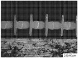
FIG. 30 is a photograph of a top view of the polymeric netting of example 1;
FIGS. 31A and 31B are photographs of a top view and a side view, respectively, of the polymeric netting of example 2;
FIG. 32A and FIG. 32B are photographs of a top view and a side view, respectively, of the polymeric netting of example 3;
FIG. 33A and FIG. 33B are photographs of a top view and a side view, respectively, of the polymeric netting of example 4;
FIG. 34A and FIG. 34B are photographs of a top view and a side view, respectively, of the polymeric netting of example 6; and is
Fig. 35 is a photograph of a test fixture used to evaluate the fluid strike-through time of examples 1, 1b, 4a, 4b, 6a, and 6 b.
FIG. 36 is a schematic front view of one embodiment of a respirator;
FIG. 37 is a schematic back view of another embodiment of a respirator;
FIG. 38 is a schematic rear view of another embodiment of a respirator;
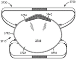
FIG. 39 is a schematic rear view of another embodiment of a respirator;
FIG. 40 is a schematic cross-sectional view of one embodiment of a filtering structure of a respirator;
FIG. 41 is a schematic plan view of an embodiment of a hearing protector;
FIG. 42 is a schematic cross-sectional view of the hearing protector of FIG. 41; and is provided with
FIG. 43 is a graph of percent strain versus time for several examples of polymer netting compared to polyurethane foam and polyurethane foam.
Detailed Description
In general, the present disclosure provides one or more embodiments of a respirator that includes a polymeric netting. In one or more embodiments, a polymeric netting can be used or included as a strap for a harness for a respirator. Additionally, in one or more embodiments, the polymeric netting can also be used in a face seal that can be disposed adjacent to the perimeter of the mask body of the respirator. And in one or more embodiments, the polymeric netting can also be used as a cover web for a respirator. Additionally, in one or more embodiments, the polymeric netting can be used in hearing protectors.
A respirator of the present disclosure may include a mask body and a harness attached to the mask body. In one or more embodiments, the harness can include one or more straps connected to the mask body on opposite sides of the mask body. Additionally, one or more of the ribbons can include a polymeric netting, as further described herein. The polymeric netting may allow air to flow through the belt, making the belt more comfortable for the wearer. Additionally, in one or more embodiments, the straps may allow moisture or perspiration that is otherwise trapped between the straps and the wearer's head to be transported away from the head, providing additional comfort to the wearer.
Belts commonly used with respirators typically include an elastomeric material, such as a woven headband or Kraton rubber. See, e.g., U.S. Pat. Nos. 6,332,465 to Xue; WO9831743 to Deeb et al; and WO9732493a1 to Bryant et al. These bands are typically solid in appearance, that is, the bands cannot be partially or fully see-through. The solid nature of the band is known to increase the overall product weight and to increase the heat retention of the wearer's neck. In addition, conventional respirator belts are configured such that the belt exhibits one color throughout. The two main belt surfaces thus have the same appearance. Therefore, it may be difficult to notice whether the tape is twisted. The tape also loses any opportunity to be aesthetically colorful or artistically pleasing by exhibiting more than one color.
In one or more embodiments, the polymeric netting used in or forming one or more belts of the harness may comprise polymeric belts and polymeric strands. Each of the polymeric ribbons and strands has a length, a width, and a height. The length is the longest dimension, the width is the shortest dimension, and the height is the dimension transverse to the length and width. Additionally, in one or more embodiments, the polymeric tapes can have a high-to-width aspect ratio of at least 5 to 1. In one or more embodiments, the major surface of each polymeric strip can be intermittently bonded to only one polymeric strand. And in one or more embodiments, the height of the polymeric ribbons can be at least 2 times greater than the height of the polymeric strands.
One or more embodiments of the respirators described herein may include a face seal that is disposed adjacent at least a portion of the perimeter of the mask body of the respirator. In one or more embodiments, the face seal may comprise or be comprised of a polymeric netting, as further described herein. Such a face seal may allow moisture to be transported away from the wearer's face, making the mask more comfortable to wear.
Common face seals used in respirators are typically made of a foam material that helps seal the mask body to the wearer's face. However, such foam materials may prevent moisture collected on the wearer's face from being transported away from the face. This trapped moisture can irritate the wearer's skin and make the mask uncomfortable.
In one or more embodiments, the polymeric netting forming or included in the face seal may comprise polymeric ribbons and polymeric strands. Each of the polymeric ribbons and strands has a length, a width, and a height. The length is the longest dimension, the width is the shortest dimension, and the height is the dimension transverse to the length and width. Additionally, in one or more embodiments, the polymeric tapes can have a high-to-width aspect ratio of at least 5 to 1. In one or more embodiments, the major surface of each polymeric strip can be intermittently bonded to only one polymeric strand. And in one or more embodiments, the height of the polymeric ribbons can be at least 2 times greater than the height of the polymeric strands.
Additionally, in one or more embodiments, the respirators described herein may comprise one or both of an inner cover web and an outer cover web, as further described herein. In one or more embodiments, one or both of the inner and outer cover webs may comprise or consist of a polymeric netting, as further described herein.
And in one or more embodiments, the polymeric netting described herein can be used to form or construct a sealing ring in an earmuff for a hearing protector.
Polymer netting
Fig. 1 shows a side view of an embodiment of a polymeric netting 10 according to the present disclosure that can be used with a respirator as, for example, a harness strap, face seal, or the like. The polymeric netting 10 includes polymeric ribbons 1 and polymeric strands 3. The polymeric tapes 1 and polymeric strands 3 each have a length, a width "w 1" and "w 3", and a height "h 1" and "h 3". The lengths of the polymeric ribbons 1 and polymeric strands 3 are the longest dimension and are not shown in fig. 1. The length is the longest dimension, the width is the shortest dimension, and the height is the dimension transverse to the length and width. The height "h 1" of the ribbons and the height "h 3" of the strands are generally between the respective lengths and widths. However, the strands 3 may also have a height "h 3" that is substantially the same as their width "w 3". For a round strand, the height and width may both refer to the diameter. At least some of the polymeric ribbons have a height-to-width aspect ratio of at least three to one. In some embodiments, at least some of the polymeric ribbons have a height-to-width aspect ratio of at least 5:1, 7:1, 8:1, 10:1, 11:1, 15:1, 20:1, 30:1, or 40: 1. The height of the polymeric ribbons is generally greater than the height of the polymeric strands. In one or more embodiments, the height of each of the polymeric ribbons is at least 2, 2.5, 3, 5, 10, or 20 times greater than the height of the individual polymeric strands. In one or more embodiments, the polymeric netting 10 may include any suitable ratio between the height h1 of one or more of the ribbons 1 and the height h3 of one or more of the strands 3. In one or more embodiments, the ratio of h1 to h3 can be at least 1:1, 2:1, 3:1, 4:1, 5:1, 6:1, etc. In one or more embodiments, the ratio of h1 to h3 can be no greater than 100:1, 50:1, 10:1, etc.
The polymeric ribbons can have any suitable height h 1. In one or more embodiments, the height of the polymeric ribbons can be in the range of 0.05 millimeters to 10 millimeters. In one or more embodiments, the height of the polymeric ribbons can be in the range of 0.05 millimeters (mm) to 3 millimeters (mm). In one or more embodiments, the height of the polymeric ribbons is greater than 750 micrometers. In one or more embodiments, the height of the polymeric ribbons can be no greater than 1 cm. In one or more embodiments, the height of the polymeric ribbons is in a range of greater than 750 micrometers to 3mm (e.g., 0.775mm to 2mm or 0.8mm to 1.5 mm). In one or more embodiments, the height of at least one of the polymeric ribbons or polymeric strands is less than 750 micrometers. In one or more embodiments, the height of at least one of the polymeric ribbons or strands is in the range of 0.1mm to less than 750 microns (e.g., 0.3mm to 0.745mm or 0.5mm to 0.745 mm).
Fig. 2 shows a perspective view of an embodiment of a polymeric netting according to the present disclosure. In this perspective view, the length "l" of the polymeric ribbons and polymeric strands can be observed.
Referring again to fig. 1-2, the polymeric ribbons 1,11,21 each have a first major surface 2,12 intermittently attached to a single polymeric strand 3, 13. That is, the two or more polymeric strands are not attached to the first major surface of the polymeric ribbons. When it is said that the first major surface of the polymeric ribbons is intermittently joined to the individual polymeric strands, it can be observed that the polymeric strands oscillate between being bonded to the polymeric ribbons and to another portion of the netting on opposite sides of the polymeric strands. In the embodiment shown in fig. 2, two adjacent polymeric ribbons 11,21 are joined together by a single polymeric strand 13 that is at least partially alternately bonded to the two adjacent polymeric ribbons 11, 21. However, this is not essential. For example, in one or more embodiments, the polymeric strands may oscillate between bonding to the polymeric ribbons and bonding to non-oscillating strands that do not have to have a high-to-wide aspect ratio of at least three to one. The polymeric ribbons typically do not intersect the polymeric strands because the major surfaces of the polymeric ribbons are intermittently bonded to the polymeric strands that are at least partially alternately bonded to the polymeric ribbons and another strand or ribbon of the netting. In any of the embodiments of the polymeric netting disclosed herein, the strands and ribbons of the polymer do not generally intersect one another substantially (e.g., at least 50% by number (at least 55%, 60%, 65%, 70%, 75%, 80%, 85%, 90%, 95%, 99%, or even 100%) do not intersect one another) by forming overlapping or interlayer intersections.
In fig. 1, the heights h1 of the polymeric ribbons 1 are all about the same size and the heights h3 of the polymeric strands 3 are all the same size, but as shown in fig. 2-4, this is not required. For example, as shown in fig. 3, there may be two different types of polymer strips 31, 41. The polymer strips 31 have a height-to-width aspect ratio that is greater than the height-to-width aspect ratio of the polymer strips 41. In fig. 2 and 4, the polymeric strips 11,21,51 have a range of heights. In fig. 4, the height-to-width aspect ratio of the polymeric ribbons 51 is greater on the edges 55 of the polymeric netting 50 than at the center 57 of the netting. In these embodiments, at least some of the polymeric ribbons 51 have a height-to-width aspect ratio of at least 3 to 1.
Although the spacing between each polymeric strip and the polymeric strands in the polymeric netting is approximately equal in fig. 1-4, this is not required. The spacing between any two adjacent polymeric ribbons 1,11,21,31,41,51 or any two adjacent polymeric strands 3,13,33,53 may vary in the cross-web direction. For example, any two adjacent polymeric ribbons or any two adjacent polymeric strands are positioned closer together at the center of the netting than on the edges, or vice versa.
In the embodiment shown in fig. 1-4, the polymeric ribbons and polymeric strands alternate. In some embodiments of polymeric netting according to the present disclosure and/or manufactured according to the techniques disclosed herein, the polymeric ribbons and polymeric strands alternate in at least a portion of the netting. In these embodiments, and even in other embodiments in which the polymeric ribbons and polymeric strands do not alternate, each major surface of the polymeric ribbons is typically intermittently bonded to only one polymeric strand. Further, it should be noted that the spacing (described herein) shown in the planar cross-sectional views of the polymeric netting shown in fig. 3-6 and 8 is idealized. In a typical cross-sectional plan view, not all of the polymeric strands will appear to be bonded to the major surface of the polymeric strip in the same manner. Instead, the position of the strands may appear more similar to that shown in the cross-sectional plan view of fig. 7 and in the side view shown in fig. 1.
As described herein, one or more polymeric strands of the polymeric netting may oscillate between the ribbons. In such embodiments, the oscillating polymer strands may form one or more spaces, openings, or pores through the mesh. For example, the polymeric netting 30 of fig. 3 includes one or more oscillating strands 33 that form one or more openings 34 in the polymeric netting. These openings in the netting 30 may allow air or other fluids to pass through the netting. In one or more embodiments, the polymeric netting 30 may be air permeable such that the polymeric netting may be considered breathable. Alternatively, in one or more embodiments, the polymer strands 33 may be non-oscillating. In one or more embodiments that include one or more non-oscillating strands, the polymeric netting may not include one or more openings or apertures. In such embodiments, the polymeric netting 30 may be impermeable to air or other fluids. In embodiments where the polymeric netting is impermeable, the polymeric netting would not be considered breathable.
In one or more embodiments, the polymeric netting of the present disclosure may be formed on a substrate or backing layer. For example, the netting 30 of FIG. 3 is disposed on a substrate 47, which may comprise any suitable material or combination of materials. In one or more embodiments, the substrate 47 can be an absorbent material. Substrates used with the polymeric netting described herein may be permeable or impermeable. In one or more embodiments, the substrate 47 can block or obstruct air or fluid that has passed through the netting 30 through the one or more apertures or openings 34 formed by the oscillating strands, such that the combination of the netting and the substrate is impermeable to air or other fluids.
Some embodiments of configurations of polymeric netting according to the present disclosure are shown in fig. 1, and 5-6. In fig. 1, the polymeric ribbons 1 each have a centerline 4 bisecting the major surface 2, and first and second edges 6 and 8 symmetrically disposed on opposite sides of the centerline 4. For each of the polymeric ribbons 1, the associated individual polymeric strands 3 are bonded to the major surface 2 at a location between the centerline 4 and the first edge 6. In the illustrated embodiment, a single polymeric strand 3 is bonded to two adjacent polymeric ribbons 1 at a location between the centerline 4 and the first edge 6. In other words, the single polymeric strand 3 is bonded to the major surface 2 closer to the first edge 6 than the second edge 8. In still other words, polymeric netting 10 has opposing first and second major surfaces 5, 7 transverse to major surface 2 of polymeric strip 1. The second major surface 7 of the polymeric netting 10 includes the second edges 8 of the polymeric ribbons 1, and the first major surface 5 of the polymeric netting 10 includes the first edges 6 of the polymeric ribbons 1 and portions of at least some of the polymeric strands 3.
In the embodiment shown in fig. 5, the polymeric ribbons 61 and polymeric strands 63 are vertically aligned. In these embodiments, a single polymeric strand 63 is bonded to major surface 62 of ribbon 61 at a location that includes centerline 64. In still other words, the polymeric netting 60 has opposing first 65 and second 67 major surfaces transverse to the major surfaces 62 of the polymeric ribbons 61. The first major surface 65 of the polymeric netting 60 includes first edges 66 of the polymeric ribbons 61 and the second major surface 67 of the polymeric netting 60 includes second edges 68 of the polymeric ribbons 61. Neither first major surface 65 nor second major surface 67 includes a portion of polymeric strands 63.
In the embodiment shown in fig. 6, the polymeric ribbons 71,81 each have a centerline 74,84 bisecting the major surface 72,82, and first top edges 78,88 and second bottom edges 76,86 symmetrically disposed on opposite sides of the centerline 74,84, with some of the polymeric ribbons 81 being bonded to their individual polymeric strands 73 at a location between the centerline 84 and the first top edge 88, and some of the polymeric ribbons 71 being bonded to their individual polymeric strands 73 at a location between the centerline 74 and the second bottom edge 76. In other words, the single polymeric strand 73 is bonded to the major surface 72 of the first portion of the polymeric strip 71 closer to the first edge 76 than the second edge 78, and the single polymeric strand 73 is bonded to the major surface 82 of the second portion of the polymeric strip 81 closer to the second edge 88 than the first edge 86. In other words, the polymeric netting 70 has opposing first 75 and second 77 major surfaces transverse to the major surfaces 72,82 of the polymeric ribbons 71, 81. The first major surface 75 of the polymeric netting 70 includes first edges 86 of the first set of polymeric ribbons 81 and the second major surface 77 of the polymeric netting 70 includes second edges 78 of the second set of polymeric ribbons 71. Neither first major surface 75 nor second major surface 77 includes a portion of polymeric strands 73. A first set of polymeric ribbons 81 do not extend to second major surface 77 and a second set of polymeric ribbons 71 do not extend to first major surface 75. Additional details regarding this embodiment can be found in co-pending U.S. patent application serial No. 64/946,592 to Legatt et al, entitled POLYMERIC NETTING OF STRANDS AND FIRST AND SECOND NETTING AND METHODS OF MAKING THE SAME (POLYMERIC NETTING OF strands AND first AND SECOND RIBBONS AND METHODS OF making the same).
Although in fig. 1-6 the widths w1 of the polymeric ribbons are each about the same and the widths w3 of the polymeric strands are each about the same, this is not required. The width of the polymeric ribbons and/or polymeric strands may vary across the netting (e.g., in a direction transverse to the length of the polymeric ribbons and polymeric strands). For example, at least one of the polymeric ribbons or strands may have a greater width w1 or w3 at the center of the netting than at the edges, or vice versa.
In the embodiment shown in fig. 1-6, the width w1 of the polymeric strip is uniform from the top edge 8,78,88 to the bottom edge 6,76, 86. Again, this is not required. For example, in fig. 7, a polymeric netting 80 is shown having strips with a non-uniform width between the top and bottom edges. This embodiment is similar to the embodiment shown in figure 5, where the polymeric ribbons 61a and polymeric strands 63a are located at the vertical center. However, in the polymeric netting 80, the width of the polymeric ribbons 61a is wider at locations including the centerline 64a than at the top and bottom edges 68, 66. That is, in the illustrated embodiment, the polymeric ribbons 61a are wider at the locations where they are bonded to the polymeric strands 63 a.
In the polymeric netting 80 shown in fig. 7, the polymeric ribbons 61a are designed to have a greater width near the centerline 64a than at the top and bottom edges 68, 66. The width of the polymeric strip may also be designed to vary in other ways from the top edge to the bottom edge. For example, the width may be greater at top edge 68 and/or bottom edge 66 than near centerline 64 a. The polymeric strands may be bonded to the polymeric ribbons at these locations. The polymeric tapes may also have random undulations in width due to the extrusion process. In any case where the width of the polymeric tapes is not uniform, the width w1 of the polymeric tapes used to determine the high-to-wide aspect ratio is measured at the smallest width of the polymeric tapes.
Similarly, the height of the polymeric ribbons can be measured at the highest height of the polymeric ribbons. The height of the polymeric ribbons is substantially uniform. The polymeric ribbons in any of the embodiments of the polymeric netting disclosed herein will not have any independent posts (e.g., mechanical fasteners or hooks) upstanding from the edges of the polymeric ribbons. Similarly, the polymeric netting disclosed herein in any of its embodiments will generally not have any free standing posts (e.g., mechanical fasteners or hooks) on either its first or second major surface.
In some embodiments, wherein the polymeric ribbons each have a centerline bisecting the major surface and first and second edges symmetrically disposed on opposite sides of the centerline, the first edges of the polymeric ribbons comprise a different composition than the second edges of the polymeric ribbons. An embodiment of such a polymeric netting is shown in fig. 8. In fig. 8, the polymeric netting 90 comprises polymeric ribbons 91 and polymeric strands 93. The polymeric strips 91 each have a first portion 91a and a second portion 91 b. The first part 91a and the second part 91b are made of different polymer compositions. Likewise, the polymeric strands 93 each have a first portion 93a and a second portion 93 b. In these embodiments, the polymeric netting 90 has opposing first 95 and second 97 major surfaces transverse to the major surface 92 of the polymeric ribbons 91. The first major surface 95 of the polymeric netting 90 includes first edges 96 of the polymeric ribbons 91 and second portions 93b of the polymeric strands 93, and the second major surface 97 of the polymeric netting 90 includes second edges 98 of the polymeric ribbons 91. The first portion 91a, and thus the second edge 98, of the polymeric strip 91 comprises a first polymeric composition, and the second portion 91b, and thus the first edge 96, of the polymeric strip 91 comprises a second polymeric composition. The first portions 93a of the polymeric strands comprise a third polymeric composition and the second portions 93b of the polymeric strands 93 comprise a fourth polymeric composition. In the exemplified embodiment, at least the first and second polymer compositions are different, and the first polymer composition does not extend to the first edge 96 of the polymeric strip 91.
Although other techniques may be useful, various embodiments of the polymeric netting disclosed herein may be produced by extrusion dies and/or methods according to the present disclosure. Extrusion dies according to the present invention have a plurality of channels from a cavity within the die to a dispensing orifice. The dispensing orifices each have: a width, which is a dimension corresponding to the width of a particular polymeric ribbon or polymeric strand; and a height, which is a dimension corresponding to the thickness of the resulting extruded polymeric netting and the height of a particular polymeric ribbon or strand.
In one or more embodiments of the extrusion die and method of making a polymeric netting according to the present disclosure, the extrusion die has at least one cavity, a dispensing surface, and a fluid passageway between the at least one cavity and the dispensing surface. The dispensing surface has an array of first dispensing orifices separated by an array of second dispensing orifices. This means that for any two first distribution orifices there is at least one second distribution orifice between them. However, for any two first dispensing orifices, there may be more than one second dispensing orifice between them, and dispensing orifices other than the second dispensing orifice may be present in a side-by-side configuration between them.
The fluid channel can physically separate the polymer from the at least one cavity (e.g., the first and second cavities, and optionally any other die cavity within the extrusion die) until the fluid channel enters the dispensing orifice. The shape of the different channels within the die may be the same or different. Examples of channel cross-sectional shapes include circular, square, and rectangular shapes. These cross-sectional shapes, the choice of polymeric material, and die swell may affect the cross-sectional shape of the ribbons and strands.
In one or more embodiments (including the embodiments shown in fig. 9-27A and 27B), the extrusion die includes at least a first cavity and a second cavity, with a first fluid passageway between the first cavity and the first dispensing orifice and a second fluid passageway between the second cavity and the second dispensing orifice. The first and second dispensing orifices each have a height and a width, the first dispensing orifices each have a height-to-width aspect ratio of at least 3:1 (in some embodiments, at least 5:1, 8:1, 10:1, 11:1, 15:1, 20:1, 30:1, or 40:1), and the height of the first dispensing orifices is greater than the height of the second dispensing orifices (in some embodiments, at least 2, 2.5, 3, 5, 10, or 20 times greater than the height of the second dispensing orifices). In some embodiments, particularly of extrusion dies, the first dispensing orifice, the second dispensing orifice, and any other dispensing orifices are arranged one after the other across the dispensing surface. That is, in these embodiments, the dispensing orifices are arranged individually or individually in the width dimension of the die, regardless of the alignment of the dispensing orifices in these embodiments. For example, the dispensing orifices are not stacked in groups of two, three or more in the height direction.
In one or more embodiments of the methods according to the present disclosure, the polymeric ribbons are dispensed from the first dispensing orifices at a first speed while the polymeric strands are dispensed from the second dispensing orifices at a second speed, and the second speed is at least 2 times greater than the first speed. In some embodiments, the second speed is in the range of 2 to 6 times or 2 to 4 times the first speed. In one or more embodiments in which the extrusion die comprises at least a first cavity and a second cavity, the first polymeric composition is provided to the first cavity of the extrusion die at a first pressure to dispense the polymeric ribbons from the array of first dispensing orifices at a first speed, and the second polymeric composition is provided to the second cavity of the extrusion die at a second pressure to dispense the polymeric strands from the array of second dispensing orifices at a second speed, wherein the second speed is at least 2 (in some embodiments, 2 to 6, or 2 to 4) times the first speed.
In one or more embodiments of the methods according to the present disclosure, the polymeric ribbons are dispensed from the first dispensing orifices at a first speed while the polymeric strands are dispensed from the second dispensing orifices at a second speed, and the first speed is at least 2 times the second speed. In one or more embodiments, the first speed is in the range of 2 to 6 times or 2 to 4 times the second speed. In one or more embodiments in which the extrusion die comprises at least a first cavity and a second cavity, the first polymeric composition is provided to the first cavity of the extrusion die at a first pressure to dispense the polymeric ribbons from the array of first dispensing orifices at a first speed, and the second polymeric composition is provided to the second cavity of the extrusion die at a second pressure to dispense the polymeric strands from the array of second dispensing orifices at a second speed, wherein the first speed is at least 2 (in some embodiments, 2 to 6, or 2 to 4) times the second speed.
While it is possible to oscillate the polymeric ribbons or strands, larger bond areas are typically observed when the polymeric strands are under oscillation. Thus, in the methods described herein, the polymer strand is described as an oscillating strand.
The dimensions of the polymeric ribbons and polymeric strands can be adjusted, for example, by the composition of the extruded polymer, the speed of the extruded strands, and/or the orifice design (e.g., cross-sectional area (e.g., height and/or width of the orifice)). As taught in PCT patent publication No. wo 2013/028654(Ausen et al), depending on the type of polymer composition and the pressure within the cavity, a dispensing surface with first polymer orifices three times larger in area than second polymer orifices may not be able to form a web with polymer ribbons that are taller than the polymer strands. In one or more embodiments of the extrusion die and method according to the present disclosure, the orifice has a height-to-width aspect ratio of at least 5: 1.
Conveniently, an extrusion die according to and/or useful for practicing the present disclosure may comprise a plurality of shims. The plurality of shims collectively define at least one cavity, a dispensing surface, and a fluid passage between the at least one cavity and the dispensing surface. In one or more embodiments, the plurality of shims comprises a plurality of sequences of shims, wherein each sequence comprises at least one first shim providing a first fluid passage between the at least one cavity and at least one of the first dispensing orifices, and at least one second shim providing a second fluid passage between the at least one cavity and at least one of the second dispensing orifices. In some embodiments, the shim collectively defines a first cavity and a second cavity, and the extrusion die has a first plurality of dispensing orifices in fluid communication with the first cavity and has a second plurality of dispensing orifices in fluid communication with the second cavity.
In some embodiments, the shims will be assembled according to a scheme that provides for a variety of different types of shim sequences. Since different applications may have different requirements, the sequence may have a variety of different numbers of pads. The sequence may be a repetitive sequence that is not limited to a specific number of repetitions in a specific region. Or the sequence may be non-regularly repeating, but a different gasket sequence may be used.
A plurality of shims that can be used to provide a polymeric netting according to the present disclosure are shown in fig. 9-11, 12A, and 12B. Referring now to fig. 9, a plan view of the gasket 100 is shown. The shim 100 may be used in the shim sequence 1000 shown in fig. 12A and 12B. Other shims that may be used in this sequence are shown in fig. 10-11. The gasket 100 has a first hole 110a, a second hole 110b, and a third hole 110 c. When the gasket sequence 1000 is assembled, the first apertures 110a, 210a, and 310a in the gaskets 100, 200, and 300 collectively define at least a portion of the first cavity 1012 a. Similarly, the second apertures 110b, 210b, and 310b in the shims 100, 200, and 300 collectively define at least a portion of the second cavity 1012b, and the third apertures 110c, 210c, and 310c in the shims 100, 200, and 300 collectively define at least a portion of the third cavity 1012 c. The shim 100 has a number of holes 147 to enable passage of, for example, bolts that secure the shim 100 and other components to be described herein into the assembly. The gasket 100 has a dispensing surface 167, and in this particular embodiment, the dispensing surface 167 has: an indexing groove 180 that can be used to conveniently align the shim with a properly shaped key during assembly of the shim into the die; and an identification notch 182 to help verify that the die has been assembled in the desired manner. The gasket 100 has shoulders 190 and 192 that may be conveniently engaged by the compression blocks 2204 described herein in connection with fig. 22-23. The gasket 100 has a dispensing opening 156 but does not have an integral connection between the dispensing opening 156 and any of the holes 110a, 110b, or 110 c. There is no connection, for example, from the cavity 110a to the dispensing opening 156 via, for example, the channel 168a, but there is a flow path 1068a to the dispensing surface when the shim 100 is assembled with the shims 200 and 300 as shown in assembly diagram 1000 (see fig. 12A). The delivery tube 154, and in particular the dispensing opening 156 at the end thereof, can be sized to provide the desired size of the polymer strands extruded therefrom. The size of the dispensing opening 156 and the size of the channel 158a also affect the desired strand speed.
Referring now to fig. 10, a plan view of shim 200 is shown. The spacer 200 has a first hole 210a, a second hole 210b, and a third hole 210 c. When the gasket 200 is assembled with other gaskets as shown in FIG. 12A, the aperture 210a helps define the first cavity 1012A, the aperture 210b helps define the second cavity 1012b, and the aperture 210c helps define the third cavity 1012 c. Shim 200 has a number of holes 247 to enable passage of, for example, bolts that secure shim 200 and other components to be described herein into the assembly. The shim 200 has a dispensing surface 267, and in this particular embodiment, the dispensing surface 267 has an indexing groove 280 and an identifying notch 282. The gasket 200 also has shoulders 290 and 292. There is no flow path from any of the chambers to the dispensing face 267 because this shim forms a non-dispensing region along the width of the die. In use, the spacer 200 separates the spacer 100 from which the polymeric strands 3 are made from the spacer 300 from which the polymeric tapes 1 are made.
Referring now to fig. 11, a plan view of a shim 300 is shown. The spacer 300 has a first hole 310a, a second hole 310b, and a third hole 310 c. When the gasket 300 is assembled with other gaskets as shown in FIG. 12A, the aperture 310a helps define the first cavity 1012A, the aperture 310b helps define the second cavity 1012b, and the aperture 310c helps define the third cavity 1012 c. The shim 300 has a number of holes 347 to enable passage of, for example, bolts that secure the shim 300 and other components to be described herein into the assembly. The shim 300 has a dispensing surface 367, and in this particular embodiment, the dispensing surface 367 has an indexing groove 380. The shim 300 also has shoulders 390 and 392. Gasket 300 has dispensing opening 356 but does not have an integral connection between dispensing opening 356 and any of apertures 310a, 310b, or 310 c. There is no connection, e.g., from hole 310c, to dispensing opening 356 via, e.g., channel 368c, but there is a flow path 1068c to the dispensing surface when gasket 300 is assembled with gaskets 100 and 200 as shown in sequence 1000 (see fig. 12A). By comparing fig. 11 with fig. 9, it will be observed that dispensing opening 356 is larger than dispensing opening 156. In some embodiments, dispensing opening 356 is at least twice the size of dispensing opening 156. In some embodiments, dispensing opening 356 is at least 2.5, 3, 5, 10, or 20 times larger than dispensing opening 156.
Fig. 12A and 12B show perspective assembly views of a shim sequence (collectively 1000) using the shims of fig. 9-11 to make the polymeric netting 10 shown in fig. 1. From left to right, the sequence 1000 includes two shims 100 of extrudable polymeric strands (e.g., polymeric strands 3 of netting 10 of fig. 1), two shims 200, two shims 300 of extrudable polymeric ribbons (e.g., polymeric ribbons 1 of netting 10 of fig. 1), and two shims 200. The first dispensing apertures 1001 each have an aspect ratio defined by a height h1001 and a width w 1001. The height-to-width aspect ratio is at least three to one (in some embodiments, at least 5:1, 8:1, 10:1, 11:1, 15:1, 20:1, 30:1, or 40: 1). The first and second dispensing orifices 1001, 1003 are separated by two instances of the shim 200. The separation results in separation of the polymeric ribbons 1 from the polymeric strands 3 in the polymeric netting 10. The height h1001 of the first dispensing orifice is greater than the height h1003 of the second dispensing orifice. In some embodiments, the height h1001 of the first dispensing orifice is at least 2, 2.5, 3, 5, 10, or 20 times greater than the height h1003 of the second dispensing orifice.
A modified version of the sequence 1000 shown in fig. 12A and 12B may be used in conjunction with the sequence 1000, for example, to produce the polymer netting 20, 30, and 50 shown in fig. 2-4. To make the polymeric netting 30 shown in fig. 3, the sequence 1000 may alternate with another sequence similar to 1000, where the gasket 300 has, for example, somewhat smaller openings 356. While the gasket 300 may be used to extrude the polymeric strip 31, a gasket having a somewhat smaller opening 356 may be used to extrude the polymeric strip 41. In some embodiments, sequence 1000 may alternate with another sequence similar to 1000 in which shim 300 is replaced with shim 100 and the flow rate of polymer from chamber 1012c may be adjusted so that the strand does not oscillate. This sequence can produce a polymeric netting in which the polymeric strands 33 oscillate between bonding to the polymeric ribbons 31 and to non-oscillating strands that do not have a high-to-wide aspect ratio of at least three to one. To make the polymeric netting 20 shown in fig. 2, the sequence 1000 may be combined with a similar sequence in which the spacers 300 are modified to have tapered openings 356, for example to provide a plurality of spacer sequences. While the gasket 300 may be used to extrude polymer strip 11, a gasket having a somewhat smaller opening 356 may be used to extrude polymer strip 21. Such a plurality of spacer sequences may be repeated in reverse order to provide a polymeric netting 50 as shown in fig. 4.
For example, in a method of making a polymeric netting as shown in fig. 1 using the extrusion die shown in fig. 12A and 12B, polymer from the first cavities 1012A emerges from the second dispensing orifices 1003 as polymer strands 3 and polymer from the third cavities 1012c emerges from the first dispensing orifices 1001 as polymer ribbons 1. The dimensions of the fluid channels and the pressures in the chambers 1012a and 1012c are typically selected such that the velocity of the oscillating polymer strands 3 is about 2 to 6 times (in some embodiments, 2 to 4 times) greater than the velocity of the polymer tape 1. To make a polymeric netting as shown in fig. 1, the second chamber 1012b is not used, but this chamber can be used to introduce another polymeric composition into the polymeric netting 10.
The sequence of shims shown in fig. 15A and 15B may be used, for example, to make a polymeric netting, such as the polymeric netting indicated by polymeric netting 60 in fig. 5. Fig. 15A and 15B illustrate a perspective assembly of a shim sequence including shim 200 as described herein in connection with fig. 10 and shims 400 and 500 as described herein in connection with fig. 13 and 14, respectively.
Referring now to fig. 13, a plan view of a shim 400 is shown. The spacer 400 has a first hole 410a, a second hole 410b, and a third hole 410 c. When the gasket 400 is assembled with other gaskets as shown in fig. 15, the aperture 410a helps define the first cavity 1112a, the aperture 410b helps define the second cavity 1112b, and the aperture 410c helps define the third cavity 1112 c. Shim 400 has a number of holes 447 to enable passage of, for example, bolts that secure shim 400 and other components to be described herein into the assembly. Spacer 400 has a dispensing surface 467, and in this particular embodiment, dispensing surface 467 has an indexing groove 480 and an identification notch 482. The spacer 400 also has shoulders 490 and 492. The gasket 400 has a dispensing opening 456 but no integral connection between the dispensing opening 456 and any of the bores 410a, 410b, or 410 c. There is no connection, for example from the bore 410c to the dispensing opening 456, via, for example, the channel 468a, but when the gasket 400 is assembled with the gaskets 200 and 500 as shown in the sequence 1100 (see fig. 15A), there is a flow path 1168a to the dispensing surface in a dimension perpendicular to the plane of the drawing. 456 can be sized to provide the desired size of the polymer strands extruded therefrom. The size of the dispensing opening 456 and the size of the passageway leading to the dispensing opening also affect strand speed.
Referring now to FIG. 14, a plan view of a shim 500 is shown. Shim 500 has first hole 510a, second hole 510b, and third hole 510 c. When the shim 500 is assembled with other shims as shown in fig. 15A and 15B, the aperture 510a helps define the first cavity 1112a, the aperture 510B helps define the second cavity 1112B, and the aperture 510c helps define the third cavity 1112 c. The shim 500 has several holes 547 to allow for passage of, for example, bolts for retaining the shim 500 and other components to be described herein secured into the assembly. The shim 500 has a dispensing surface 567, and in this particular embodiment, the dispensing surface 567 has an indexing groove 580. Shim 500 also has shoulders 590 and 592. Shim 500 has dispensing opening 556 but does not have an integral connection between dispensing opening 556 and any of apertures 510a, 510b, or 510 c. There is no connection, e.g., from bore 510b to dispensing opening 556 via, e.g., passage 568b, but there is a flow path 1168b to the dispensing surface when gasket 500 is assembled with gaskets 200 and 400 as shown in the assembled view (e.g., fig. 15A).
Fig. 15A and 15B show perspective assembly views of a shim sequence (collectively 1100) using the shims of fig. 10 and 13-14 to make the polymeric netting 60 shown in fig. 5. From left to right, the sequence 1100 includes four shims 400 of extrudable polymeric strands 63, four shims 200, two shims 500 of extrudable polymeric ribbons 61, and four shims 200. Dispensing orifices 1101 and 1103 are separated by four instances of gasket 200. The separation results in separation of the polymeric ribbons 61 from the polymeric strands 63 in the polymeric netting 60. The shim sequence 1100 is similar to the shim sequence 1000 except that the dispensing orifices 1101 and 1103 are vertically aligned such that the second dispensing orifice is located in the middle of the cross-section of the dispensing surface 1167. As in the embodiment shown in fig. 12B, the first dispensing orifices 1101 each have an aspect ratio of at least three to one (in some embodiments, at least 5:1, 8:1, 10:1, 11:1, 15:1, 20:1, 30:1, or 40:1) defined by a height h1101 and a width w1101, and the height h1101 of the first dispensing orifices is at least 2, 2.5, 3, 5, 10, or 20 times greater than the height h1103 of the second dispensing orifices.
For example, in a method of making a polymeric netting as shown in fig. 5 using the extrusion die shown in fig. 15A and 15B, polymer from the first cavities 1112a emerges from the second dispensing orifices 1103 as polymer strands 63 and polymer from the second cavities 1112B emerges from the first dispensing orifices 1101 as polymer ribbons 61. The dimensions of the fluid channels and the pressures in the cavities 1112a and 1112b are typically selected such that the velocity of the oscillating polymer strands 63 is about 2 to 6 times (in some embodiments, 2 to 4 times) greater than the velocity of the polymer ribbons 61. To make a polymeric netting as shown in fig. 5, the third lumen 1112c is not used, but may be used to introduce another polymeric composition into the polymeric netting 60.
The sequence of shims shown in fig. 18A and 18B may be used, for example, to make a polymeric netting, such as the polymeric netting indicated by polymeric netting 70 in fig. 6. Fig. 18A and 18B illustrate a perspective assembly of a shim sequence including shims 200 and 300 as described herein in connection with fig. 10 and 11, respectively, and shims 600 and 700 as described herein.
Referring now to fig. 16, a plan view of a shim 600 is shown. The gasket 600 has a first hole 610a, a second hole 610b, and a third hole 610 c. When the gasket 600 is assembled with other gaskets as shown in fig. 18A, the aperture 610a helps define a first cavity 1212a, the aperture 610b helps define a second cavity 1212b, and the aperture 610c helps define a third cavity 1212 c. Shim 600 has several holes 647 to allow, for example, passage of bolts for holding shim 600 and other components to be described herein secured in the assembly. The insert 600 has a dispensing surface 667 and, in this particular embodiment, the dispensing surface 667 has indexing grooves 680 and identifying notches 682. Shim 600 also has shoulders 690 and 692. Gasket 600 has dispensing opening 656 but no integral connection between dispensing opening 656 and any of holes 610a, 610b, or 610 c. There is no connection, e.g., from hole 610b to dispensing opening 656, e.g., via channel 668b, but there is a flow path 1268b to the dispensing surface when gasket 600 is assembled with gaskets 200, 300 and 700 as shown in sequence 1200 (see fig. 18A). 656 can be sized to provide the desired size of the polymer strands extruded therefrom. The size of the dispensing opening 656, as well as the size of the channel leading to the dispensing opening, also affects strand speed.
Referring now to fig. 17, a plan view of shim 700 is shown. Shim 700 is similar to shim 300 shown in FIG. 11. Shim 700 has first hole 710a, second hole 710b, and third hole 710 c. When the shim 700 is assembled with other shims as shown in fig. 18A and 18B, the aperture 710a helps define the first cavity 1212a, the aperture 710B helps define the second cavity 1212B, and the aperture 710c helps define the third cavity 1212 c. Shim 700 has a number of holes 747 to enable passage of, for example, bolts that secure shim 700 and other components to be described herein into the assembly. The shim 700 has a dispensing surface 767, and in this particular embodiment, the dispensing surface 767 has an indexing groove 780. The gasket 700 also has shoulders 790 and 792. Shim 700 has dispensing opening 756 but no integral connection between dispensing opening 756 and any of bores 710a, 710b, or 710 c. There is no connection, for example, from the orifice 710a to the dispensing opening 756 via, for example, the channel 768A, but there is a flow path 1268A to the dispensing surface when the gasket 700 is assembled with the gaskets 200, 300 and 600 as shown in the assembled view (e.g., fig. 18A). As in fig. 11, dispensing opening 756 is larger than dispensing opening 656. In some embodiments, dispensing opening 756 is at least twice the size of dispensing opening 656. In some embodiments, dispensing opening 756 is at least 2.5, 3, 5, 10, or 20 times larger than dispensing opening 656.
Fig. 18A and 18B show perspective assembly views of a shim sequence (collectively 1200) using the shims of fig. 10-11 and 16-17 to make the polymeric netting 70 shown in fig. 6. From left to right, sequence 1200 includes two shims 700 of extrudable polymeric strips 81, two shims 200, two shims 600 of extrudable polymeric strands 73, two shims 200, two shims 300 of extrudable polymeric strips 71, two shims 200, two shims 600 of extrudable polymeric strands 73, and two shims 200. The first dispensing apertures 1201 each have a height-to-width aspect ratio of at least three to one (in some embodiments, at least 5:1, 8:1, 10:1, 11:1, 15:1, 20:1, 30:1, or 40: 1). The dispensing orifices 1201 and 1203 are separated by a spacer 200, resulting in polymeric ribbons 71 and 81 being separated from polymeric strands 73 in the polymeric netting 70. As in the embodiment shown in fig. 12B, the height h1201 of the first dispensing orifice is at least 2, 2.5, 3, 5, 10, or 20 times greater than the height h1203 of the second dispensing orifice. In the methods disclosed herein, polymer from the first cavity 1212a emerges from the first dispensing orifice 1201 as a polymeric strip 81, polymer from the second cavity 1212b emerges from the second dispensing orifice 1203 as an oscillating strand 73, and polymer from the third cavity 1212c emerges from the first dispensing orifice 1201 as a polymeric strip 71. The dimensions of the fluid channels and the pressure in the cavities are typically selected such that the velocity of the oscillating polymer strands 73 is about 2 to 6 times (in some embodiments, 2 to 4 times) greater than the velocity of the polymer ribbons 71 and 81.
The shim sequence shown in fig. 21A and 21B may be used, for example, to make a polymeric netting, such as the polymeric netting indicated by polymeric netting 80 in fig. 7. Fig. 21A and 21B illustrate a perspective assembly of a shim sequence including shims 200 and 500 and shims 800 and 900 as described herein in connection with fig. 10 and 14, respectively.
Referring now to fig. 19, a plan view of a shim 800 is shown. The gasket 800 has a first hole 810a, a second hole 810b, and a third hole 810 c. When shim 800 is assembled with other shims as shown in fig. 21A and 21B, aperture 810a helps define first cavity 1312a, aperture 810B helps define second cavity 1312B, and aperture 810c helps define third cavity 1312 c. The shim 800 has several holes 847 to enable passage of, for example, bolts that secure the shim 800 and other components to be described herein into the assembly. The shim 800 has a dispensing surface 867, and in this particular embodiment, the dispensing surface 867 has an indexing groove 880 and an identification notch 882. Shim 800 also has shoulders 890 and 892. The gasket 800 has a dispensing opening 856 but no integral connection between the dispensing opening 856 and any of the holes 810a, 810b, or 810 c. There is no connection, e.g., from bore 810a to dispensing opening 856, e.g., via passage 868a, but there is a flow path 1368a to the dispensing surface when shim 800 is assembled with shims 200, 500, and 900 as shown in sequence 1300 (see fig. 21A).
Referring now to fig. 20, a plan view of a gasket 900 is shown. Shim 900 has first hole 910a, second hole 910b, and third hole 910 c. When shim 900 is assembled with other shims as shown in fig. 21A and 21B, aperture 910a helps define first cavity 1312a, aperture 910B helps define second cavity 1312B, and aperture 910c helps define third cavity 1312 c. The gasket 900 has a number of holes 947 to enable passage of, for example, bolts that secure the gasket 900 and other components described herein to the assembly. The shim 900 has a dispensing surface 967, and in this particular embodiment, the dispensing surface 967 has an indexing groove 980 and an identifying notch 982. Shim 900 also has shoulders 990 and 992. Gasket 900 has dispensing opening 956 but no integral connection between dispensing opening 956 and any of apertures 910a, 910b, or 910 c. There is no connection, e.g., from hole 910b to dispensing opening 956 via, e.g., channel 968b, but there is a flow path 1368b to the dispensing surface when gasket 900 is assembled with gaskets 200, 500 and 800 as shown in the assembled view (e.g., fig. 21A). 956 can be sized to provide the desired size of the polymer strands extruded therefrom. Fig. 21A and 21B show perspective assembly views of a shim sequence (collectively 1300) using the shims of fig. 10, 14, 19, and 20 to make the polymeric netting 80 shown in fig. 7. From left to right, sequence 1300 includes three shims 800 of extrudable polymeric strands 63a, three shims 200, one shim 900 that may extrude a portion of polymeric strip 61a about centerline 64a, two shims 500 of extrudable polymeric strip 61a, another shim 900 that may extrude a portion of polymeric strip 61a about centerline 64a, and three shims 200. Both shim 900 and shim 500 extrude polymer from cavity 1312b, although dispensing opening 956 is much smaller than dispensing opening 556. Openings 956 and 556 are positioned at the vertical center so that more polymer is extruded from cavity 1312b into the central portion of polymeric strip 61 a. Dispensing orifices 1301 and 1303 are separated by shim 200, resulting in polymeric ribbons 61a being separated from polymeric strands 63a in polymeric netting 80. The first dispensing apertures 1301 each have a height h1301 to width w1301 aspect ratio of at least three to one (in some embodiments, at least 5:1, 8:1, 10:1, 11:1, 15:1, 20:1, 30:1, or 40:1) when the width w1301 is measured at the narrowest point of the first dispensing aperture. As in the embodiment shown in fig. 12B, the height h1301 of the first dispensing orifices is greater than the height h1303 of the second dispensing orifices (in some embodiments, at least 2, 2.5, 3, 5, 10, or 20 times greater than the height of the second dispensing orifices).
For example, in a method of making a polymeric netting as shown in fig. 7 using the extrusion die shown in fig. 21A and 21B, polymer from the first cavities 1312a emerges from the second dispensing apertures 1303 as polymer strands 63a, and polymer from the second cavities 1312B emerges from the first dispensing apertures 1301 as polymer ribbons 61A. The dimensions of the fluid channels and the pressure in the cavities 1312a and 1312b are typically selected such that the velocity of the oscillating polymeric strands 63a is about 2 to 6 times (in some embodiments, 2 to 4 times) greater than the velocity of the polymeric ribbons 61 a. To make a polymeric netting as shown in fig. 7, the third cavity 1312c is not used, but this cavity can be used to introduce another polymeric composition into the polymeric netting 80.
A modification of the shim sequence shown in fig. 21A and 21B may be used to provide polymeric netting similar to those shown in fig. 7 but having polymeric ribbons in which more polymer is extruded from cavity 1312B to at least one of bottom edge 66 or top edge 68 rather than to central portion 64 a.
An exploded perspective view of an embodiment of a mount suitable for use in an extrusion die constructed from multiple repetitions of a shim sequence is shown in fig. 22-23. In one or more embodiments of the extrusion dies described herein, there will be a large number of very thin shims (typically thousands of shims; in some embodiments, at least 1000, 2000, 3000, 4000, 5000, 6000, 7000, 8000, 9000, or even at least 10,000) that are of different types (e.g., shims 100, 200, and 300) and are compressed between two endblocks (e.g., 2244a and 2244 b). Conveniently, through bolts may be used to assemble the shims to the end blocks 2244a and 2244b, passing through the holes 547 in the shims. Inlet fittings 2250a, 2250b and 2250c are provided on end blocks 2244a and 2244b, respectively, for introducing material to be extruded into the extrusion die 2000. In one or more embodiments, the inlet fittings 2250a, 2250b, and 2250c connect to a conventional type melting apparatus assembly. In one or more embodiments, cartridge heaters 2052 are inserted into sockets in the extrusion die 2000 to maintain the material to be extruded at a desired temperature while in the die. One of ordinary skill in the art will recognize alternatives for assembling an extrusion die other than the one shown in the illustrated embodiment. In one or more embodiments, the assembled gasket (conveniently bolted between the end blocks) further comprises a manifold body (not shown) for supporting the gasket. The manifold body has at least one (or a plurality (e.g., two or three, four or more)) of manifolds therein, the manifolds having outlets. An expansion seal (e.g., made of copper or an alloy thereof) is provided to seal the manifold body and the gasket such that the expansion seal defines a portion of at least one of the cavities (in one or more embodiments, a portion of all of the cavities), and such that the expansion seal allows a conduit to be formed between the manifold and the cavities.
The compression blocks 2204 have notches 2206 that conveniently engage shoulders on the shim (e.g., shoulders 590 and 592 on shim 500). When mount 2000 is fully assembled, compression blocks 2204 are attached to back plate 2208 by, for example, mechanical bolts. Referring now to fig. 23, a perspective view of mount 2000 of fig. 22 is shown in a partially assembled state. Several shims (e.g., shim 500) are in their assembled position to show how they fit within mount 2000, but most of the shims used to make up the assembly die have been omitted for visual clarity.
In any of the shims and sequences described herein, the shims may have a thickness in the range of 50 microns to 500 microns, although thicknesses outside this range may also be useful. For wider fluid channels and orifices, several shims of smaller thickness may be stacked together, or a single shim having the desired channel width may be used. The gasket is typically a metal, such as stainless steel. To reduce dimensional changes under thermal cycling, metal shims are typically heat treated. The shim may be manufactured by conventional techniques including wire electrical discharge machining and laser machining. Typically, multiple shims are manufactured simultaneously by stacking multiple sheets and then simultaneously creating the desired openings. The variability of the flow path is preferably within 0.025mm (1 mil), more preferably within 0.013mm (0.5 mil). The spacers are tightly compressed to prevent gaps between the spacers and polymer leakage. For example, bolts of 12mm (0.5 inch) diameter are typically used and tightened to their recommended torque rating at extrusion temperatures. In addition, the shims are aligned to provide uniform extrusion through the extrusion orifice, as misalignment can result in the strands being extruded at an angle from the die, which inhibits the desired bonding of the netting. To aid in alignment, indexing grooves may be cut into the shim to receive alignment keys, as described herein. In addition, a vibration table may be used to provide smooth surface alignment of the extrusion tip.
Typically, the fluid channels have a height in the range of 50 microns to 3mm and a length of less than 5mm (smaller lengths are generally preferred for tapering channel thicknesses), although heights and lengths outside these ranges may also be useful. The height of the first dispensing orifice may be in the range of 50 micrometers to 3 millimeters (mm). In one or more embodiments, the height of the first dispensing orifice is greater than 750 microns. In one or more of these embodiments, the height of the first dispensing orifice is in the range of greater than 750 microns to 3mm (e.g., 0.775mm to 3mm or 0.8mm to 2.6 mm). In one or more embodiments, the height of at least one of the first dispensing orifice or the second dispensing orifice is less than 750 microns. In one or more of these embodiments, the height of the first and second dispensing orifices is in the range of 0.1mm to less than 750 microns (e.g., 0.3mm to 0.745mm or 0.5mm to 0.745 mm).
In one or more embodiments of the die that may be used to extrude polymers, each of the first and second dispensing orifices has a width, and each of the first and second dispensing orifices is separated by at least the width of the respective dispensing orifice and is at most 2 times the width of the respective dispensing orifice. Where the dispensing apertures have different widths, the separation spacing between the first and second apertures may be at least the width of the wider opening and at most 2 times the width of the wider opening. The spacing between the orifices should be sufficient to maintain the distance between adjacent strands as they exit the die. This spacing accommodates die swell at the dispensing tip. If the spacing between the orifices is too large, the strands and ribbons will not repeatedly collide with one another after extrusion at different speeds and will not form a repeat bond of the polymeric netting.
Generally, it has been observed that the rate of strand bonding is proportional to the extrusion speed of polymer strands or ribbons extruded at faster speeds. In addition, it has been observed that the bonding rate can be increased, for example, by increasing the polymer flow rate for a given orifice size or by decreasing the orifice area for a given polymer flow rate. It has also been observed that the distance between bonds is inversely proportional to the rate of strand bonding and directly proportional to the speed at which the web is pulled away from the die. Thus, it is believed that the distance between bonds and web basis weight can be independently controlled by the design of the orifice cross-sectional area, the belt exit speed, and the extrusion rate of the polymer. For example, relatively high basis weight netting having a relatively short bonding pitch can be made by extrusion at a relatively high polymer flow rate, a relatively low netting exit velocity, using a die with a relatively small second orifice area.
In one or more embodiments, it may be useful to vary the number of polymeric ribbons per centimeter of transverse width across the width of the polymeric netting. One way to accomplish this is to apply a spreading force to at least a portion of the polymeric netting, such as by running the web over a curved roll, diverging rail, or diverging disk. Once unfolded, attachment of the polymeric netting to another layer (e.g., a carrier layer or a layer in an absorbent article as described herein) can be used to maintain the web in such an unfolded state. Spreading in the cross-machine direction causes the openings in the polymeric netting to become larger in the cross-machine direction, with the original size of the individual openings in the machine direction being defined by the average longitudinal spacing of the contact points between the polymeric ribbons and the polymeric strands. In one or more embodiments, the polymeric netting may be stretched in the machine direction or in both the cross direction and the machine direction to create larger openings and/or to reduce the weight and cost of the polymeric netting on a per unit area basis. Uniaxial stretching in the machine direction, which is the length direction of the polymeric tapes and strands, can be performed by advancing the web on rolls with gradually increasing speeds. A common stretching method that allows for uniaxial, sequential biaxial, or simultaneous biaxial stretching of a thermoplastic web utilizes a flat film tenter apparatus. Such an apparatus grips a thermoplastic web using a plurality of clips, clamps, or other edge gripping devices along opposite edges of the web in the following manner: uniaxial, sequential biaxial, or simultaneous biaxial stretching in the desired direction is obtained by advancing the grasping device at varying speeds along the diverging rails. Increasing the clip speed in the machine direction generally results in machine direction stretch. Uniaxial and biaxial stretching can be accomplished, for example, by the methods and apparatus disclosed in U.S. patent No.7,897,078 to Petersen et al and the references cited therein. Flat film tenter stretching equipment is commercially available, for example, from brukener machinery, west gesdov, Germany (bruckner Maschinenbau GmbH, Siegsdorf, Germany).
While in the embodiment shown in fig. 9-21, the first and second dispensing orifices are collinear, this is not required. In one or more embodiments, the first dispensing orifices are collinear with each other and the second dispensing orifices are collinear with each other, but the first dispensing orifices and the second dispensing orifices do not overlap. When the first and second dispensing orifices do not overlap one another, it may be desirable to extrude the strands horizontally.
While the embodiments of extrusion dies and methods described herein in connection with fig. 9-21 provide polymeric ribbons and polymeric strands of a polymeric netting by separate cavities, other embodiments include providing an extrusion die comprising a plurality of shims positioned adjacent to one another, the shims collectively defining a cavity, the extrusion die having a plurality of first dispensing orifices in fluid communication with the cavity and a plurality of second dispensing orifices in fluid communication with the cavity such that the first dispensing orifices alternate with the second dispensing orifices. In these embodiments, the polymeric ribbons are dispensed from the first dispensing orifices at a first speed while the polymeric strands are dispensed from the second dispensing orifices at a second speed, wherein the second speed is at least 2 (in some embodiments, 2 to 6 or 4 to 6) times the first speed. Since there is only one lumen, the polymeric ribbons and polymeric strands in the resulting netting are made of the same composition. To make a polymeric netting from an extrusion die having only one cavity, a shim sequence such as shown in fig. 44-48 in PCT patent publication No. wo 2013/028654 to Ausen et al may be useful, but with the following modifications: the shim providing the first dispensing orifice of the polymeric strip has an aspect ratio of at least 5:1 and may lack a restriction set back from the dispensing orifice.
In any of the foregoing embodiments, the polymer compositions useful in the polymer netting and methods described herein may be the same or different. In some embodiments, the polymeric ribbons and polymeric strands comprise different polymeric compositions. These webs may be prepared by using different polymer compositions in the first and second cavities, for example by extrusion using any of the embodiments of the methods described herein. The different polymer compositions in the polymeric ribbons and polymeric strands may be selected to achieve their surface properties or their bulk properties (e.g., tensile strength, elasticity, microstructure, color, refractive index, etc.). In addition, the polymer composition may be selected to provide specific functional or aesthetic properties in the polymer netting, such as hydrophilicity/hydrophobicity, elasticity, softness, hardness, stiffness, bendability, or color. The term "different" with respect to the polymer composition may also refer to at least one of the following: (a) a difference of at least 2% of at least one infrared peak, (b) a difference of at least 2% of at least one nuclear magnetic resonance peak, (c) a difference of at least 2% of number average molecular weight, or (d) a difference of at least 5% of polydispersity.
In one or more embodiments of the methods disclosed herein, the polymers used to make the polymeric ribbons and polymeric strands can be selected to be compatible with each other such that the polymeric ribbons and polymeric strands are bonded together at the bond regions. Bonding generally refers to melt bonding, and the bond between the polymeric strands and the polymeric tapes can be considered to be melt bonded. Bonding occurs in a relatively short period of time (typically less than 1 second). The bonded regions on the major surfaces of the polymeric ribbons and the polymeric strands are typically cooled by air and natural convection and/or radiation. In one or more embodiments, in selecting polymers for the polymeric ribbons and polymeric strands, it may be desirable to select polymers having bonding strands with dipole interactions (or H-bonds) or covalent bonds. It has been observed that the bonding between the strands is improved by increasing the time to melt the polymeric tapes and the polymeric strands to enable more interaction between the polymers. It has generally been observed that polymer adhesion is improved by reducing the molecular weight of at least one polymer and/or introducing additional comonomers to improve polymer interaction and/or reduce the rate or amount of crystallization.
Examples of polymeric materials that can be used to make the polymeric netting include thermoplastic polymers. Suitable thermoplastic polymers for the polymeric netting include: polyolefin homopolymers such as polyethylene and polypropylene, copolymers of ethylene, propylene and/or butylene; ethylene-containing copolymers such as ethylene vinyl acetate and ethylene acrylic acid; ionomers based on sodium or zinc salts of ethylene methacrylic acid or ethylene acrylic acid; polyvinyl chloride; polyvinylidene chloride; polystyrene and polystyrene copolymers (styrene-maleic anhydride copolymers, styrene acrylonitrile copolymers); nylon; polyesters such as poly (ethylene terephthalate), polyvinyl butyrate, and polyethylene naphthalate; polyamides such as poly (hexamethylene adipamide); a polyurethane; a polycarbonate; poly (vinyl alcohol); ketones, such as polyetheretherketone; polyphenylene sulfide; a polyacrylate; a cellulosic plastic; fluoroplastic; polysulfones; a silicone polymer; and mixtures thereof. The dies and methods according to the present disclosure can also be used to co-extrude a crosslinkable (e.g., by heat or radiation) polymeric material. When a thermally curable resin is used, the die may be heated to initiate curing, thereby adjusting the viscosity of the polymeric material and/or the pressure in the corresponding mold cavity. In some embodiments, at least one of the polymeric ribbons or strands is made of a polyolefin (e.g., polyethylene, polypropylene, polybutylene, ethylene copolymers, propylene copolymers, butylene copolymers, and copolymers and blends of these materials).
In one or more embodiments, the polymeric ribbons are elastic, the polymeric strands are elastic, or both the polymeric ribbons and the polymeric strands are elastic. For example, the second polymeric composition can include thermoplastic elastomers such as ABA block copolymers, polyurethane elastomers, polyolefin elastomers (e.g., metallocene polyolefin elastomers), polyamide elastomers, ethylene vinyl acetate elastomers, polyvinyl ethers, acrylics, particularly those having long chain alkyl groups, polyalphaolefins, asphalt, silicones, polyester elastomers, and natural rubber. ABA block copolymer elastomers are typically elastomers in which the a blocks are polystyrenes and the B blocks are conjugated dienes (e.g., lower alkylene dienes). The a block is typically formed primarily of substituted (e.g., alkylated) or unsubstituted styrenic moieties (e.g., polystyrene, poly (alpha-methylstyrene), or poly (tert-butylstyrene)) and has an average molecular weight of about 4,000 to 50,000 grams/mole. The B block is typically formed predominantly of a conjugated diene, which may be substituted or unsubstituted (e.g., isoprene, 1, 3-butadiene, or ethylene-butylene monomers), and has an average molecular weight of about 5,000 to 500,000 g/mole. The A and B blocks may be configured in, for example, a linear, radial, or star configuration. ABA block copolymers may comprise a plurality of a blocks and/or B blocks, which may be made from the same or different monomers. Typical block copolymers are linear ABA block copolymers where the a blocks may be the same or different, or block copolymers having more than three blocks and predominantly terminated by a blocks. The multi-block copolymer can contain, for example, a proportion of an AB diblock copolymer, which tends to form more tacky elastomeric film segments. Other elastomeric polymers may be blended with the block copolymer elastomer, and various elastomeric polymers may be blended to give them different degrees of elastomeric properties.
Various types of thermoplastic elastomers are commercially available, including those available under the trade designation "STYROFLEX" from BASF, Florham Park, N.J.), Kentum Polymers under the trade designation "KRATON" from Houston, Tex (Kraton Polymers, Houston, Tex.), Claudin Polymers under the trade designation "PELLETHANE", "ENGAGE", "INFUSE", "SIFT" or "NORDEL" from Dow Chemical, Midland, Mich.), from Dismantane, Hollanden, Netherlands, Inc. (E.I. Du Pont Company, Neerland, Wilmington, Tex.), and thermoplastic elastomers under the trade designation "HYTREL" from Tex Doxon, Tex.
Mixtures of any of the above polymers may be used in the polymeric netting disclosed herein. For example, polyolefins may be blended with elastomeric polymers to reduce the modulus of the polymer composition, which may be desirable for certain applications. Such blends may or may not be elastomeric.
In some embodiments, polymeric materials useful in making the polymeric netting include colorants (e.g., pigments and/or dyes) for functional (e.g., optical effects) and/or aesthetic purposes (e.g., each having a different color/shade). Suitable colorants are those known in the art for use in a variety of polymeric materials. Exemplary colors imparted by the colorant include white, black, red, pink, orange, yellow, green, aqua, purple, and blue. In some embodiments, it is desirable to have a degree of opacity for one or more of the polymeric materials. The amount of colorant to be used in a particular embodiment can be readily determined by one skilled in the art (e.g., to achieve a desired color, hue, opacity, transmission, etc.).
The shape of the individual polymeric ribbons and polymeric strands in the polymeric netting disclosed herein may depend on a variety of factors. As described herein, polymer strands that are lower in height than the polymer tapes can exit the die at a faster rate than the polymer tapes and can be in oscillation. Thus, in some embodiments, the polymeric tapes can be substantially straight, for example, when no extension force is applied on the polymeric netting as shown, for example, in fig. 31A, 32A, and 33A. However, depending on the height difference between the polymeric ribbons and strands, the placement of the polymeric strands on the major surfaces of the polymeric ribbons, and the modulus of the materials used to make the polymeric ribbons and strands, both the polymeric ribbons and strands may occupy a sinusoidal path in the length direction as shown, for example, in fig. 2. In some embodiments, the polymeric ribbons may exit the die at a faster rate than the polymeric strands and may be in oscillation. In these embodiments, the polymeric strands may appear substantially straight, for example, when no extension force is applied to the polymeric netting.
In one or more embodiments, individual strands of polymeric strands or individual strips of polymeric ribbons in the netting can comprise different polymeric compositions. For example, one or more of the polymeric strands in a polymeric netting may have a core made of one polymeric composition and a sheath made of a different polymeric composition. Such netting may be extruded as described in PCT patent publication No. wo 2013/032683 to Ausen et al. Netting in which the opposite major surfaces were made from different polymer compositions is described in co-pending application serial No. 61/779997 filed on 3/13 of 2013.
In one or more embodiments, as described herein in connection with fig. 8, the polymeric ribbons each have a centerline bisecting the major surface and first and second edges symmetrically disposed on opposite sides of the centerline, wherein the first edges of the polymeric ribbons comprise a different composition than the second edges of the polymeric ribbons. In an exemplary embodiment, the polymeric strand also has a centerline bisecting the major surface and first and second edges symmetrically disposed on opposite sides of the centerline, wherein the first edge of the polymeric strand comprises a different composition than the second edge of the polymeric strand. A polymer netting, such as the polymer netting indicated by polymer netting 90 in fig. 8, may be conveniently manufactured, for example, using the shim sequence 3000 shown in fig. 27A and 27B. Fig. 27A and 27B show a perspective assembly of a shim sequence comprising shims 3100, 3200, and 3300 as described herein.
Referring now to fig. 24, a plan view of the shim 3100 is shown. The gasket 3100 has a first hole 3110a, a second hole 3110b, a third hole 3110c and a fourth hole 3110 d. When the pad 3100 is assembled with other pads as shown in fig. 27A and 27B, the first aperture 3110a will help define the first cavity 3012a, the second aperture 3110B will help define the second cavity 3012B, the third aperture 3110c will help define the third cavity 3012c, and the fourth aperture 3110d will help define the fourth cavity 3012 d. As will be discussed in more detail herein, the molten polymer in the cavities 3012a and 3012d can be extruded into a polymeric strip 91 having two layers 91a and 91b, and the molten polymer in the cavities 3012b and 3012c can be extruded into polymeric strands 93 having two layers 93a and 93b, as shown in fig. 8.
The shim 3100 has several holes 3147 to enable passage of, for example, bolts that secure the shim 3100 and other components to be described herein into the assembly. The shim 3100 has a dispensing opening 3156 in the dispensing surface 3167. It may appear that there is no path from the holes 3110a and 3110d to the dispensing opening 3156 via, for example, the channels 3168a and 3168d, but that there are flow paths 3068a and 3068d in a dimension perpendicular to the plane of the shim when the sequence of fig. 27A is, for example, fully assembled. Similar to shim 100, the dispensing surface 3167 of shim 3100 has an indexing groove 3180, an identification notch 3182, and shoulders 3190 and 3192.
Referring now to fig. 25, a plan view of gasket 3200 is shown. The gasket 3200 has a first hole 3210a, a second hole 3210b, a third hole 3210c, and a fourth hole 3210 d. When the shim 3200 is assembled with other shims as shown in fig. 27A and 27B, the first aperture 3210a will help define the first cavity 3012a, the second aperture 3210B will help define the second cavity 3012B, the third aperture 3210c will help define the third cavity 3012c, and the fourth aperture 3210d will help define the fourth cavity 3012 d. Similar to shim 3100, shim 3200 has a dispensing surface 3267, and in this particular embodiment, dispensing surface 3267 has indexing groove 3280. Otherwise similar to shim 3100, shim 3200 has shoulder 3290 and shoulder 3292. There is no passageway from either of the cavities to the dispensing surface 3267 because this shim forms a non-dispensing region along the width of the die. Referring again to fig. 8, a shim 3200 may be used to separate the shim 3100 from which the polymeric strips 91 are made from the shim 3300 from which the polymeric strands 93 are made.
Referring now to fig. 26, a plan view of shim 3300 is shown. The shim 3300 has a first hole 3310a, a second hole 3310b, a third hole 3310c, and a fourth hole 3310 d. When shim 3300 is assembled with other shims as shown in fig. 27A and 27B, first holes 3310a will help define first cavity 3012a, second holes 3310B will help define second cavity 3012B, third holes 3310c will help define third cavity 3012c, and fourth holes 3310d will help define fourth cavity 3012 d. Similar to the pad 3100, the pad 3300 has a dispensing surface 3367, and in this particular embodiment, the dispensing surface 3367 has an indexing groove 3280 and an identification recess 3282. Otherwise similar to shim 3100, shim 3300 has shoulders 3390 and 3392. The pad 3300 has a dispensing opening 3356 in the dispensing surface 3367. It may appear that there is no path from the holes 3010b and 3010c to the dispensing opening 3356, respectively, via, for example, the channels 3368b and 3368c, but that there is a flow path in the dimension perpendicular to the plane of the shim when the sequence of fig. 27A is, for example, fully assembled.
Referring now to fig. 27A and 27B, there are shown perspective assembly views of a shim sequence (collectively 3000) that uses the shims of fig. 24-26 to make the polymeric netting 90 of fig. 8. More specifically, from left to right in fig. 27B, the sequence 3000 includes four instances of the shim 3200, four instances of the shim 3300 of the extrudable polymeric strands 93, four instances of the shim 3200, and two instances of the shim 3100 of the extrudable polymeric strip 91. Dispensing orifices 3001 and 3003 are separated by spacers 3200, resulting in polymeric ribbons 91 being separated from polymeric strands 93 in polymeric netting 90. The first dispensing apertures 3001 each have a height h3001 to width w3001 aspect ratio of at least three to one (in some embodiments, at least 5:1, 8:1, 10:1, 11:1, 15:1, 20:1, 30:1, or 40: 1). In fig. 27B, the width of the first dispensing orifice can be considered to be the width of two shims 3100. As in the embodiment shown in fig. 12B, the height h3001 of the first dispensing orifice 3001 is at least 2, 2.5, 3, 5, 10, or 20 times greater than the height h3003 of the second dispensing orifice. In this embodiment, at least the first dispensing orifice 3001 is defined by an array of first antechambers, and the die includes a first fluid passageway 3168a between the first cavity 3012a and one of the first antechambers, and a fourth fluid passageway 3168d extending from the fourth cavity 3012d to the same antechamber, such that the area of entry of the first fluid passageway 3168a into the first antechamber is lower than the area of entry of the fourth fluid passageway 3168d into the first antechamber. The extrusion die further comprises a fluid channel extending from one of the cavities with the die to the second dispensing orifice. In the exemplified embodiment, the second distribution orifices 3003 are defined by an array of second antechambers, and the die comprises a second fluid passage 3168b located between the second cavity 3012b and one of the second antechambers, and a third passage 3168c extending from the third cavity 3012c to the same antechamber, such that the area where the second fluid passage 3168b enters the second antechamber is lower than the area where the third fluid passage 3168c enters the second antechamber.
In other embodiments where the first edge of the polymeric strip comprises a different composition than the second edge of the polymeric strip, the polymeric netting may be surface treated with a surfactant (e.g., in an amount between about 0.05 to 0.5 weight percent). If a surfactant is used, it may be an internal additive in the polymer composition that migrates to the surface, or the surfactant may be applied to the web by any conventional method (e.g., spraying, printing, dipping, or brushing). The polymeric compositions (e.g., those that provide the second portions 91b and 93b shown in fig. 8) can be selected to be hydrophilic or to contain a surfactant, or a surfactant can be applied to a major surface of the polymeric netting to impart a desired level of wettability and hydrophilicity to at least a portion of the polymeric netting for certain applications.
In any of the foregoing embodiments of the polymeric netting according to the present disclosure and/or made by the method according to the present disclosure, the distance between bonds may be in the range of 0.5mm to 20mm (in some embodiments, in the range of 0.5mm to 10 mm). Additionally, in any of the preceding embodiments, the polymeric netting according to or made by the methods disclosed herein can have a thickness of between 5g/m 2To 750g/m2(in some embodiments, 5g/m2To 400g/m2Or 10g/m2To 200g/m2) Basis weight within the range. In some embodiments, in any of the preceding embodiments, the polymeric netting disclosed herein has a thickness of up to 4mm (in some embodiments, up to 3.5mm, 3mm, 2mm, 1mm, 0.75mm, or less than 0.75 mm; in a range of 10 microns to 4mm, 10 microns to 3.5mm, 10 microns to 3mm, 10 microns to 2mm, 10 microns to 1mm, 10 microns to 750 microns, 10 microns to less than 750 microns, 10 microns to 749 microns, 10 microns to 700 microns, or 10 microns to 650 microns).
Polymeric netting according to and/or made according to the present disclosure may be used, for example, in absorbent articles. Accordingly, the present disclosure provides absorbent articles comprising a polymeric netting according to the present disclosure. Personal care absorbent articles, such as diapers, training pants, adult incontinence garments and feminine hygiene pads (e.g., sanitary napkins and pantiliners), and wound care absorbent articles (e.g., wound dressings and bandages), are typically constructed using a skin-facing fluid permeable topsheet, a garment-facing fluid impermeable backsheet, and an absorbent core therebetween. An exploded schematic view of an example of an embodiment of an absorbent article 3400 according to the present disclosure is shown in figure 28. In absorbent articles according to the present disclosure, the absorbent core 3460 is generally interposed between the polymeric netting and the backsheet 3440. Polymeric netting may be useful, for example, as at least one of the topsheet 3410 or acquisition/distribution layer 3480. In the exemplified embodiment, the polymeric netting forms the topsheet 3410. When used as an acquisition/distribution layer 3480, a polymeric netting can also be positioned between the absorbent core 3460 and the backsheet 3440 or within the absorbent core 3460 (e.g., between two tissue sheets 3490).
Polymeric netting according to the present disclosure may be advantageously used as a topsheet in absorbent articles. Referring to fig. 28, the topsheet 3410 is the layer which rests on the user's skin and is thus the first layer to be in contact with liquids or other exudates of the user. The topsheet is advantageously used for several purposes, including keeping the absorbent material contained within the article, allowing rapid passage of fluid to the absorbent core, providing a skin-friendly, comfortable contact surface for the skin with which the article is in contact, keeping the skin clean and dry, and helping to prevent absorbed fluid from contacting the skin. When used as a topsheet 3410 for a hygiene article, the polymeric netting can have a configuration as shown, for example, in any of fig. 1-4 and 8. In these configurations, the polymeric ribbons 1 each have a centerline 4 bisecting the first major surface 2 and first and second edges 6, 8 symmetrically disposed on opposite sides of the centerline 4, with the polymeric strands 3 bonded to the first major surface 2 at a location closer to the first edge 6 than the second edges 8. In other words, referring to fig. 3, the polymeric strands 33 are all disposed toward the same first edge of the polymeric ribbons 31,41 such that both the polymeric ribbons and the polymeric strands can contact the absorbent body 47. This configuration also provides a greater surface area on one side of the polymeric netting 40 for adhesive bonding of the netting to the absorbent body. However, in other embodiments, the configurations shown in fig. 5-7 may be useful.
In any of the configurations shown in fig. 1-7, the following examples indicate that in some embodiments, the polymeric netting can have at least one of the following features: the ability to rapidly absorb fluid, direct fluid along the longitudinal direction of the material, provide a high degree of rewet resistance, present a dry to skin-contacting surface after exposure to fluid, and provide a cleansing action to the skin due to the flexibility of the strip-like elements, driven by natural body movements, thereby creating a cleaner and drier skin for the wearer of an absorbent hygiene article using this new topsheet material.
In the absorbent article 3400 according to the present disclosure, as shown in fig. 28, the backsheet 3440, sometimes referred to as the outer cover, is the layer farthest from the user. The backsheet is typically formed from a thermoplastic film (e.g., a polyethylene film) that is substantially impervious to liquids. The backsheet serves to prevent body exudates absorbed by the absorbent core from wetting or contaminating the wearer's garments, bedding, or other materials that contact the absorbent article. Various materials for the backsheet may be suitable for use in absorbent articles according to the present disclosure. For example, the backsheet may comprise a polyethylene film (e.g., having an initial thickness of about 0.5 mil (0.012 mm) to about 5.0 mil (0.12 mm)), a woven or nonwoven web constructed or treated to impart a desired level of liquid impermeability, a laminate of a woven or nonwoven fabric and a thermoplastic film, or a microporous "breathable" material that is substantially impermeable to liquids and vapor or gas permeable. Films useful as backsheets may be, for example, embossed and/or matte treated to provide a more aesthetic appearance.
In absorbent articles according to the present disclosure, the absorbent core (e.g., shown in 3460 in fig. 28) typically comprises natural, synthetic or modified natural organic polymers that can absorb and retain liquids (e.g., aqueous liquids). In one or more embodiments, the polymer is crosslinked. The term "crosslinked" refers to any means effective to render a material that is normally water-soluble into a material that is substantially water-insoluble but swellable. Such absorbent materials are typically designed to quickly absorb and hold liquid, and generally do not release. The size and absorbent capacity of the absorbent core typically correspond to the size of the intended wearer and the amount of liquid load imparted by the intended use of the absorbent article. Various absorbents can be useful, such as cellulosic materials (e.g., wood pulp fluff), hydrophilic, synthetic meltblown fibers, superabsorbent polymers (SAP), acrylic foam absorbents (such as those described in U.S. patent No.5,817,704 to Shiveley et al and references cited therein, prepared by polymerization of high internal phase emulsions), and any combination thereof. The absorbent material may be zoned and its composition selected to move liquid from an initial location of insult to a more remote storage location. In some embodiments, the absorbent core may include one or more substantially hydrophilic tissue sheets 3490 to help maintain the structural integrity of the absorbent core, for example. The tissue sheet, which may be one wrapped around to provide both major facial surfaces of the absorbent core, may comprise absorbent cellulosic material (e.g., creped tissue or high wet strength tissue). In one or more embodiments, the tissue sheets may be configured to rapidly distribute liquid over the absorbent core. In these embodiments, the tissue sheet may be considered a distribution layer that can move fluid from the point of initial deposition to a location where storage is desired.
Some absorbent articles include an acquisition layer 3480 that can be used to quickly accept an insult and absorb, hold, direct or otherwise manage the liquid so that it does not leak outside the article. The acquisition layer may also be referred to as, for example, a surge layer, intake layer, transfer layer, or transport layer. For infants, for example, the acquisition layer is typically capable of handling gushes of between about 60 and 100 milliliters (mL) with a gush volume flow rate of about 5 to 20 mL/sec. The acquisition layer is generally below the topsheet at the surface opposite the user's skin. Various woven and nonwoven webs and foams may be used to construct the acquisition layer. The acquisition layer may be comprised of a substantially hydrophobic material, and the hydrophobic material may optionally be treated with a surfactant or otherwise treated to impart a desired level of wettability and hydrophilicity. In some embodiments, the acquisition layer 3480 may have a generally uniform caliper and cross-sectional area. The polymeric netting according to the present disclosure may be used as an acquisition layer in combination with a conventional topsheet (e.g., the nonwoven or apertured film described herein), as a topsheet in combination with a conventional acquisition layer, or in some embodiments as a substitute for both conventional topsheets and acquisition layers. In other words, when the polymeric netting according to the present disclosure is used as a topsheet, the need for an acquisition layer may be eliminated.
Suitable conventional attachment techniques may be used to assemble absorbent articles according to the present disclosure. When used as the topsheet 3410, polymeric netting according to the present disclosure can be attached to the absorbent core 3460 or acquisition layer 3480 (if used) using at least one of adhesive bonding (e.g., using water-based, solvent-based, or heat activated adhesives), thermal bonding, ultrasonic bonding, needling, or pin aperturing. When used as an acquisition layer 3480, the polymeric netting according to the present disclosure may be attached to both the conventional topsheet and the absorbent core 4060 using any of these methods as well. If adhesive bonding is used, the amount of adhesive added should be sufficient to provide the desired level of bonding without unduly restricting the flow of liquid into the absorbent core 4060.
When used as topsheets in absorbent articles, the polymeric netting can overcome the disadvantages of conventional topsheet materials. For diapers, incontinence articles and feminine hygiene pads, conventional types of topsheets are generally divided into two main groups: nonwovens and apertured films. Nonwovens have the advantage of being soft and cloth-like in feel. The nonwoven may be rendered hydrophilic (e.g., by treatment with a surfactant) to allow rapid fluid transfer through the nonwoven to the absorbent body. Such hydrophilic materials tend to feel wet to the user, possibly due to small amounts of fluid retained in the nonwoven. The retained fluid in the nonwoven also makes the fluid more visible, which is undesirable. Some hydrophilic nonwovens also have a tendency to direct fluid to the side edges of the pad, which can lead to side leakage. For the purpose of achieving softness and dry feel in nonwoven topsheets, sometimes the nonwoven is made of hydrophobic fibers. The use of hydrophobic fibers generally results in improved dry feel, but the hydrophobic nonwoven may not allow rapid fluid transfer into the pad. Sometimes hydrophobic nonwovens can cause fluid to pool on the surface of the pad, which can also lead to leakage. An advantage of using apertured films as topsheets for absorbent articles is that they provide a relatively clean and dry surface as the exudates pass through the film layer and into the interior of the pad. A disadvantage of such film-based topsheets is that they do not provide the softness and comfort provided by nonwoven topsheets.
When used as an absorbent article, the structure of the polymeric netting according to the present disclosure, in which its polymeric ribbons are separated from each other by substantially shorter polymeric strands, creates a plurality of air flow channels along the length of the polymeric ribbons that allow air to circulate between the absorbent and the wearer's skin even when the first edge of the polymeric ribbons remote from the absorbent is in contact with the wearer's skin. These channels, which are not present in conventional topsheet materials, can provide a dry and comfortable feel. The first edge of the polymeric strip extending above the height of the polymeric strands is free to flex and bend in response to any lateral force applied thereto (e.g., by movement of a user). The flexibility of the polymeric strips increases the soft feel to the user's skin. It is also believed that the ability of the polymeric strips to flex allows them to provide a cleaning action when the absorbent article is slightly offset in its position relative to the user's skin. When the first edge of the polymeric strip contacts the user's skin, small movements of the user (e.g., walking) can cause the polymeric strip to bend, which can allow the polymeric strip to contact the droplets on the user's skin and pull them downward to contact the absorbent body. In this way, the polymeric strip acts as a small scraper for removing liquid from the skin.
In addition, as shown in table 1 in the examples below, the structure of the polymeric netting according to one or more embodiments of the present disclosure (in which the polymeric ribbons thereof are separated from each other by significantly shorter polymeric strands) allows fluid to be distributed to a greater extent in the absorbent article in the longitudinal direction than in a conventional pad. Better fluid distribution may prevent leakage in the absorbent article.
With polymeric netting according to the present disclosure and/or made according to the methods disclosed herein, it may be useful to spread the polymeric ribbons away from each other to a greater extent in one portion of the absorbent article than in other portions (e.g., using the methods described herein). Attaching the unrolled polymeric netting to the absorbent body of the article or to another layer can be used to hold the web in such an unrolled state. Deployment in certain locations allows the properties of the polymeric netting to be tailored to provide, for example, different uptake rates and other performance characteristics near the transverse centerline of the article as compared to near the transverse edges of the article. However, in some embodiments, it may be desirable to spread the web consistently in the cross-machine direction across the entire width of the polymeric netting.
When the polymeric netting is used in an absorbent article, the polymer composition selected for the polymeric ribbons and polymeric strands can be hydrophobic or hydrophilic as desired. Additional material modifiers (e.g., surfactants) can be added to at least one of the polymeric ribbons or strands to alter its hydrophilicity or to adjust the manner in which the liquid interacts with the polymeric netting. For example, the polymeric ribbons can be made relatively hydrophilic to allow faster fluid penetration through the polymeric netting, while the polymeric strands can be made hydrophobic to minimize rewet. Or various configurations of polymeric netting, such as those shown in fig. 6 and 8, may be used to adjust the hydrophilicity of the polymeric netting. For example, in fig. 6, if the polymeric netting 70 is positioned on the absorbent such that the polymeric strips 71 extend away from the absorbent and the polymeric strips 81 are in contact with the absorbent, the polymeric strips 71 can be made hydrophilic to draw fluid into the absorbent, while the polymeric strips 81 can be made hydrophobic to minimize rewet. In fig. 8, if the polymeric netting 90 is positioned on the absorbent body such that the second portions 91b of the polymeric ribbons and the second portions 93b of the polymeric strands are in contact with the absorbent body, at least the first portions 91a of the polymeric ribbons can be made hydrophilic to draw fluid into the absorbent body, while at least one of the second portions 91b of the polymeric ribbons or the second portions 93b of the polymeric strands can be made hydrophobic to minimize rewet. In some embodiments, it may also be desirable to have an opposite hydrophilic pattern, for example, where the polymeric ribbons or portions thereof extending away from the absorbent body and toward the skin are more hydrophobic than the polymeric ribbons, strands or portions thereof positioned on the absorbent body. Variations of these techniques can be used to provide a gradient of hydrophilicity in the polymer netting. These hydrophilicity and hydrophobicity gradients may also be used in other applications of the polymeric netting described herein, such as polymeric netting that does not include an absorbent body.
Polymeric netting according to the present disclosure may also be used, for example, as part of a cleaning device, such as a wipe or sponge. The cleaning action provided by the polymeric tapes described herein in conjunction with the absorbent article may also make the polymeric netting disclosed herein useful for cleaning hard surfaces. In many cases, the surface of the cleaning sheet being cleaned may be too flat and therefore only the leading edge of the cleaning sheet will be loaded with material. Various techniques have been disclosed for providing a cleaning sheet with raised portions or a cleaning sheet with recessed portions to more effectively trap and retain dirt, dust and debris across a working surface. See, for example, U.S. patent No.7,757,334 to Patel et al, and U.S. patent publication nos. 2007-0136967 to Tochacek et al and 2009-0144923 to Tuman et al. It is believed that the first edge of the polymeric strip may serve to scoop up debris during use at the working surface of the cleaning wipe or sponge, and the channels in the polymeric netting may help deliver the debris to the retaining surface within the wipe or sponge.
Polymeric netting according to the present disclosure may also be used, for example, as an elastic wrap. Such wraps may be used, for example, in medical and athletic applications. For example, polymeric netting according to the present disclosure may be used for compression therapy, where external pressure is applied to the vascular element to increase interstitial pressure. The resulting amelioration of venous return and reduction of various symptoms (e.g., venous ulceration and edema) make compression therapy a useful treatment in, for example, venous and lymphatic diseases. A polymeric netting used as a wrap 3500 according to the present disclosure is shown in fig. 29. The web structure of wrap 3500 allows for bi-directional stretch and high breathability. Any conventional fastener (e.g., adhesive or mechanical fastener) may be used to secure the wrap.
The polymeric netting useful as a wrap may have any of the configurations shown in fig. 1-8. When used as a wrap, when the polymeric ribbons in the polymeric netting disclosed herein are positioned in any of their embodiments to contact the wearer's skin, the portions of the polymeric ribbons extending above the height of the polymeric strands are free to flex and bend in response to any lateral force exerted on the top of the ribbons. In other words, the polymeric ribbon ends of the polymeric ribbons are free to bend over the polymeric strands. Due to this movement, it is believed that micro-muscular movement during wear is more comfortable than elastic wraps without this deflecting behavior. The deflection of the polymeric strips makes the compression wrap feel soft to the touch and spongy.
Further, when the polymeric netting disclosed herein is used as a wrap in any of its embodiments, the polymeric ribbons on one major surface of the netting can be interlaced with the polymeric ribbons on the opposite surface of the polymeric netting when the polymeric netting is in a wrapped configuration. Depending on the materials used in the netting, these interlaced strips may exhibit adhesion to each other and may help secure the wrap on the wearer. For example, the configurations of fig. 5 and 6 (e.g., examples 2 to 4) may exhibit this behavior.
In embodiments where the polymeric ribbons and polymeric strands are different colors, a polymeric netting useful as a wrap, for example, may have a unique aesthetic appeal. For example, fig. 29 is a perspective view of a foot showing an embodiment of a polymeric netting used as a wrap according to the present disclosure. Using a different color in the polymeric tapes than the polymeric strands can create iridescence, where the color of the wrap appears to be different depending on the angle of observation. Thus, in one or more embodiments, polymeric netting useful as a wrap in accordance with the present disclosure has polymeric ribbons that are a different color than the polymeric strands. When different polymeric tapes 31 and 41 or 71 and 81, as shown for example in fig. 3 and 6, are present in the polymeric netting, it may be useful that the different polymeric tapes may be of different colors.
In the embodiment shown, for example, in fig. 6, three different colors of polymers may be used to make the polymeric ribbons 71, polymeric strands 73, and polymeric ribbons 81. When the polymeric ribbons 71 are viewed at an angle, the polymeric netting 70 may appear to be primarily the color of the ribbons 71. When the polymeric netting 70 is viewed at an angle, the polymeric netting 81 may appear to be primarily the color of the strips 81, and when the polymeric netting is viewed directly (e.g., as in the configuration schematically shown in fig. 6), all three colors may be visible.
In some applications, polymeric netting according to the present disclosure and/or made according to the methods disclosed herein may be used, for example, to form a barrier between filtration layers of a filter pack and/or to provide stiffness and support to a filter media. In some embodiments, several layers of netting are used, wherein each layer is positioned to provide optimal filtration. Additionally, in some embodiments, the elastic characteristics of some of the polymeric netting disclosed herein can accommodate filter expansion when the filter is full.
In addition to the above applications, the polymeric netting made according to the present disclosure and/or according to the methods disclosed herein may be used in a variety of other applications, including harness straps and face seals for respirators, as surface layers for surgical drapes and clothing, medical padding (cast padding), tape (including for medical applications), pest control articles (e.g., mosquito nets), geotextile applications (e.g., erosion control fabrics), water/steam management in clothing, reinforcement of nonwoven articles (e.g., paper towels), self-stacking articles (e.g., for packaging) in which polymer netting thickness is increased by stretching the polymer netting with polymer strips and polymer strands having very different moduli or elasticities, floor coverings (e.g., carpets and temporary pads), grip supports (e.g., for tools and sporting articles), and pattern coated adhesives.
In one or more embodiments, polymeric netting according to the present disclosure and/or made according to the disclosure is attached to a carrier to facilitate handling or preparation of the laminate for a selected application. For example, the polymeric netting can be attached to the carrier by lamination (e.g., extrusion lamination), adhesive (e.g., pressure sensitive adhesive), or other bonding techniques (e.g., ultrasonic bonding, compression bonding, or surface bonding).
The carrier may be continuous (i.e., without any through-going holes) or discontinuous (e.g., containing through-going perforations or holes). The carrier can comprise a variety of suitable materials, including woven webs, nonwoven webs (e.g., spunbond webs, hydroentangled webs, airlaid webs, meltblown webs, and bonded carded webs), fabrics, plastic films (e.g., single or multilayer films, coextruded films, laterally laminated films, or films comprising a foam layer), and combinations thereof. In some embodiments, the carrier is a fibrous material (e.g., a woven, nonwoven, or knitted material). Examples of materials used to form thermoplastic films or thermoplastic fibers for fibrous carriers include polyolefins (e.g., polyethylene, polypropylene, polybutylene, ethylene copolymers, propylene copolymers, butylene copolymers, and copolymers and blends of these polymers), polyesters, and polyamides. The fibers may also be multicomponent fibers, for example, having a core of one thermoplastic material and a sheath of another thermoplastic material. In some embodiments, the carrier comprises a plurality of nonwoven layers having, for example, a combination of at least one meltblown nonwoven layer and at least one spunbond nonwoven layer, or any other suitable nonwoven material. For example, the support may be a spunbond-meltblown-spunbond, spunbond-spunbond or spunbond-spunbond multilayer material. Alternatively, the carrier may be a composite web comprising a nonwoven layer and a dense film layer. Useful carriers can have any suitable basis weight or thickness as desired for a particular application. For fibrous carriers, the basis weight can range, for example, from at least about 5 grams per square meter, 8 grams per square meter, 10 grams per square meter, 20 grams per square meter, 30 grams per square meter, or 40 grams per square meter, up to about 400 grams per square meter, 200 grams per square meter, or 100 grams per square meter. The support may have a thickness of up to about 5mm, about 2mm, or about 1mm, and/or may have a thickness of at least about 0.1mm, about 0.2mm, or about 0.5 mm.
In one or more embodiments in which the polymeric netting is made of a thermoplastic, the thermoplastic may be attached to the fibrous web carrier using surface bonding or loft-retaining bonding techniques. The term "surface-bonded" when referring to bonding of fibrous materials means that at least a portion of the fibrous surface of the fibers is melt-bonded to at least a portion of the polymeric netting in such a manner that: in such a manner as to substantially retain the original (pre-bonded) shape of the polymeric netting and to substantially retain at least a portion of the polymeric netting in an exposed condition in the surface-bonded regions. Quantitatively, surface-bonded fibers may differ from embedded fibers in that at least about 65% of the surface area of the surface-bonded fibers is visible above the polymeric netting in the bonded portion of the fibers. Detecting from more than one angle may be necessary to make the entire surface area of the fiber visible. The term "loft-retaining bonding" when referring to bonding of fibrous materials means that the bonded fibrous materials include a loft that is at least 80% of the loft exhibited by the materials prior to the bonding process or in the absence of the bonding process. As used herein, the loft of a fibrous material is the ratio of the total volume occupied by the web (including fibers and void spaces of the material not occupied by fibers) to the volume occupied by the fibrous material alone. If only a portion of the fibrous web is bonded to the polymeric netting, the retained loft can be readily determined by comparing the loft of the fibrous web in the bonded regions to the loft of the web in the unbonded regions. In some cases, it may be convenient to compare the loft of the bonded web to the loft of a sample of the same web prior to bonding, for example, where the entire fibrous web has a polymeric netting bonded thereto. In some of these embodiments, the connecting comprises spraying a heated gaseous fluid (e.g., ambient air, dehumidified air, nitrogen, inert gas, or other gas mixture) onto the first surface of the fiber web carrier while the fiber web carrier is moving; spraying a heated fluid onto a major surface of a polymeric netting as the continuous web moves; and contacting the first surface of the fibrous web with a polymeric netting such that the first surface of the fibrous web is melt bonded (e.g., surface bonded or bonded with loft-retaining bonds) to the polymeric netting. The impinging of the heated gaseous fluid onto the first surface of the fibrous web and the impinging of the heated gaseous fluid onto the major surface of the polymeric netting may be performed sequentially or simultaneously. Additional methods and apparatus for joining a continuous web to a fibrous carrier web using a heated gaseous fluid can be found in U.S. patent publication nos. 2011/0151171 and 2011/0147475 to Biegler et al.
In one or more embodiments in which the polymeric netting is attached to the carrier, one or more regions of the carrier may comprise one or more elastically stretchable materials that extend in at least one direction upon application of a force and return to about its original dimension after removal of the force. In some embodiments, at least the portion of the carrier attached to the plurality of strands of backing or loop material is non-stretchable. In some embodiments, the portion of the carrier joined to the plurality of strands has an elongation in the CD of up to 10% (in some embodiments, up to 9%, 8%, 7%, 6%, or 5%). In some embodiments, such constructions can be subjected to mechanical activation (e.g., ring rolls) to render them elastic. In some embodiments, the carrier may be stretchable but inelastic. In other words, the carrier can have an elongation of at least 5%, 10%, 15%, 20%, 25%, 30%, 40%, or 50%, but does not substantially recover from the elongation (e.g., recovery of up to 10% or 5%). Suitable stretchable carriers may include nonwovens (e.g., spunbond meltblown spunbond, or carded nonwovens). In some embodiments, the nonwoven may be a high elongation carded nonwoven (e.g., HEC). In some embodiments, the support is not pleated.
Breathing apparatus
As described herein, various embodiments of the polymeric netting of the present disclosure can be used in many different applications. For example, in one or more embodiments, the polymeric netting can be used with a respirator. For example, fig. 36 is a schematic front view of a respirator 3600. The respirator 3600 may include any suitable respirator, such as a filtering face-piece respirator. Additionally, in one or more embodiments, the respirator 3600 can be a pre-formed respirator or a flat-fold respirator, as further described herein.
The respirator 3600 can include a mask body 3610 and a harness 3630. The mask body 3610 can include an exterior surface 3618 and an interior surface (e.g., interior surface 3719 of respirator 3700 of fig. 37). The mask body 3610 can also include a perimeter 3612 that includes a perimeter upper section 3614 and a perimeter lower section 3616.
The mask body 3610 can have a curved, hemispherical cup shape such as shown in fig. 36. See also U.S. Pat. No.4,536,440 to Berg and U.S. Pat. No.4,807,619 to Dyrud et al. Other shapes for the mask body 3610 can be used, as desired. For example, the mask body 3610 can be a cup-shaped mask having the construction shown in U.S. Pat. No.4,827,924 to Japuntich. The mask body 3610 may also be part of a flat-fold respirator, such as those disclosed in U.S. Pat. Nos. 6,722,366 and 6,715,489 to Bostock; d459,471 and D458,364 to Curran et al; d448,472 and D443,927 to Chen; and U.S. patent publication No.2008/0271737 to Facer et al. See also U.S. Pat. Nos. 4,419,993, 4,419,994, 4,300,549, 4,802,473 and Re.28,102.
The one or more strips 3632,3634 may be made of any suitable material or combination of materials. For example, in one or more embodiments, one or more strips 3632,3634 can include a polymeric netting. The belt may comprise any suitable polymeric netting described herein, such as polymeric netting 10 of fig. 1. For example, referring to the netting 10 of fig. 1, the polymeric netting may include polymeric ribbons 1 and polymeric strands 3. Each of the polymeric ribbons 1 and polymeric strands 3 has a length (not shown in fig. 1, but would extend into the plane of the figure), a width (e.g., width w1 of ribbon 1 and width w3 of strands 3) and a height (e.g., height h1 of ribbon 1 and h3 of strands 3), where the length is the longest dimension, the width is the shortest dimension, and the height is the dimension transverse to the length and width.
The polymeric ribbons 1 of the polymeric netting 10 can include any suitable high-to-width aspect ratio as described herein. For example, in one or more embodiments, one or more of the polymeric ribbons 1 can have a height-to-width aspect ratio of at least 5 to 1. Additionally, the polymeric tapes 1 may be bonded to the polymeric strands 1 in any suitable location. In one or more embodiments, the major surface 2 of one or more polymeric ribbons 1 can be intermittently bonded to only one polymeric strand 3. And the height of the one or more lanes 1 of polymeric netting 10 may be at least 2 times greater than the height of the one or more polymeric strands 3, as further described herein.
Further, in one or more embodiments, the strap 3632,3634 may have any suitable width. For example, in one or more embodiments, one or both of the bands may have a width of at least 1/32 inches. In one or more embodiments, one or both of the bands can have a width of no greater than 1 inch.
The straps 3632,3634 engage the mask body 3610 at attachment points 3650 and 3652 on a first side 3606 and a second side 3608 of the mask body 3610, respectively. Strap 3632,3634 may be directly engaged to the mask body by being secured to the mask body using staples or other suitable mechanical fasteners. Alternatively, the strap 3632,3634 can be secured to the mask body 3610 physically or chemically through the use of bonding including welding or adhesive attachment. Ultrasonic welding may be used, for example, to secure the strap to the mask body 3610. When the strap 3632,3634 is welded to the mask body 3610, the polymer netting in the strap can melt to form a solid, non-porous plastic that mates with the polymer material comprising the mask body. Typically, the polymeric material in the strands and/or ribbons of the polymeric netting is melted into or bonded with the polymeric material in the fibers of the layer contained in the mask body.
The mask body 3610 can also have a nose clip 3660 secured thereto that allows the wearer to conform the mask body to the wearer's nose in the sinus region 3604. An exhalation valve (not shown) can be secured to the mask body 3610 if desired to help quickly displace or purge exhaled air from the interior gas space. The exhalation valve is typically attached to the mask body 3610 at a central location. When the respirator 3600 is a filtering face-piece respirator (such as the respirator shown in fig. 36), the mask body 3610 can include a filtering structure that includes one or more layers of filter media, shaping layers, and/or cover webs, such as the filtering structure 4070 shown in fig. 40, and described further herein. A respirator having this construction may be assembled as described in U.S. Pat. No.7,131,442 to Kronzer et al.
The first and second belts 3632,3634 of the harness 3630 may include any suitable polymeric netting described herein. In one or more embodiments, the strap 3632,3634 can include one, two, three, or more layers of a polymeric netting. For example, one or both of the straps 3632,3634 may include first and second layers of polymeric tie material juxtaposed in an abutting manner. The layers may be bonded together as a melt in the die. The layers may generally have some natural affinity for each other such that mixing and bonding between the materials at the interface holds the layers together during the molten state. The two flow streams of the two layers may come together within the die and exit as a double stranded product. Thus, the first and second layer netting may be secured directly to each other. Alternatively, other layers may be interposed between the two layers such that they are disposed between the two layers in the final product. The first netting layer may have a first color different from a color of the second netting layer. The use of different colors may add aesthetic appeal to the strap, and may also allow a user to more easily detect whether the strap is in a twisted state. As shown, the netting layers may be secured to each other such that the arrays of polymeric strands in each of the layers correspond to each other when viewed from a plane projected onto the major surface of the belt. The strap 3632,3634 can be configured to be sufficiently porous such that the strap is air permeable from the first major surface to the second major surface. The ribbons 3632,3634 can have a series of openings or spaces between the ribbons through which air can pass and the strands (e.g., ribbons 1 and strands 3 of the polymeric netting 10 of fig. 1).
The filtering structures used in connection with respirators suitable for use in connection with the present disclosure may take a variety of different shapes and configurations. As shown in fig. 40, the filter structure 4070 may have multiple layers, including a fibrous filtration layer 4078 and one or more fibrous cover webs 4072,4074. When the respirator is a molded face mask, the mask body can also include a shaping layer 4076. See, for example, the following U.S. patents: U.S. Pat. No.6,923,182 to Angadjivand et al; no.7,131,442 to Kronzer et al; U.S. Pat. Nos. 6,923,182 and 6,041,782 to Angadjivand et al; 4,807,619 to Dyrud et al; and U.S. Pat. No.4,536,440 to Berg. The filter structure removes contaminants from the ambient air and may also act as a barrier layer to liquid splashes entering the mask interior. The outer cover web may be used to prevent or slow any liquid splatter and the inner filter structure may contain such splatter if it soaks through other layers. The filter structure may be a particle capture filter or a gas and vapor type filter. The filter structure may include similar or dissimilar filter media and one or more layers of cover webs, as the application requires. If the respirator contains a fluid impermeable mask body with one or more filter cartridges attached thereto. See, for example, the following U.S. patents: no.6,874,499 to Viner et al; nos. 6,277,178 and D613,850 to Holmquist-Brown et al; RE39,493 to Yuschak et al; d652,507, D471,627, and D467,656 to Mittelstadt et al; and D518,571 to Martin. The filter structure may be disposed within the filter cartridge. The filter structure located in the filter cartridge does not require shaping layers to support them.
Fig. 40 shows a filter structure 4070 in cross-section. The filter structure 4070 can include one or more cover webs 4072 and 4074, a shaping layer 4076, and a filtration layer 4078. The cover web 4072,4074 may be located on the outside of the filter structure 4078 to capture any fibers that may be loose from the filter structure. Generally, the cover web 4072,4074 should be made of fibers selected to provide comfort, particularly on the side 4071 of the filter structure 4070 that contacts the wearer's face. The construction of the various filtration layers, shaping layers, and cover webs that may be used in connection with the filtering structures used in the respirators of the present disclosure are described in more detail herein.
Filter layer
The filtering structures that can be advantageously used in the respirators of the present disclosure are typically at low pressure drops (e.g., less than about 195 to 295 pascals at a face velocity of 13.8 centimeters per second) to minimize the breathing effort of the mask wearer. In addition, the filtration layers are flexible and have sufficient shear strength so that they substantially retain their structure under the expected conditions of use. Examples of particulate capture filters include one or more webs of fine inorganic fibers (such as glass fibers) or polymeric synthetic fibers. Webs of synthetic fibers may include electret charged polymeric microfibers prepared by processes such as melt blowing. Polyolefin microfibers formed from electrically charged polypropylene are particularly useful in particle capture applications.
The filtration layer is typically selected to achieve the desired filtration effect. Generally, the filtration layer will remove a high percentage of particles and/or other contaminants from the gas stream passing therethrough. For fibrous filter layers, the fibers are selected according to the type of material to be filtered, and are typically selected so that they do not stick together during the manufacturing operation. As noted, the filter layer can have a variety of shapes and forms, and typically has a thickness of about 0.2 millimeters (mm) to 1 centimeter (cm), more typically about 0.3mm to 0.5cm, and can be a generally planar web, or it can be corrugated to provide an enlarged surface area. See, for example, U.S. Pat. Nos. 5,804,295 and 5,656,368 to Braun et al. The filtration layer may also include multiple filtration layers that are joined together by adhesive or any other technique. Essentially any suitable material known (or later developed) for forming a filter layer may be used as the filter material. Meltblown webs such as those found in Wente, Van A., Superfine Thermoplastic Fibers,48Indus, Engn, chem.,1342et seq. (1956) (ultra fine Thermoplastic Fibers) Webs of meltblown fibers mentioned in the society of chemical engineers, volume 48, page 1342, et seq, 1956), particularly in the form of permanently charged (electret) webs, are particularly useful (see, e.g., U.S. patent No.4,215,682 to Kubik et al). These meltblown fibers may be microfibers having an effective fiber diameter less than about 20 microns (μm) (referred to as "blown microfibers," BMF for short), and are generally microfibers of about 1 to 12 μm. Effective fiber diameter can be determined according to the following references: davies, c.n., The Separation Of air Dust crystals, institutional Of Mechanical Engineers, London, Proceedings 1B,1952(Davies, c.n., "Separation Of Airborne Dust and Particles", society Of Mechanical Engineers, London, Proceedings 1B, 1952). Particularly preferred are BMF webs comprising fibers formed from polypropylene, poly (4-methyl-1-pentene), and combinations thereof. Charged fibrillated film fibers as taught in U.S. patent re.31,285 to van Turnhout, as well as rosin wool webs and glass fiber webs or solution blown webs, or electrostatically sprayed webs (particularly in the form of microfibers) may also be suitable. The electrical charge may be applied to the fibers by contacting the fibers with water, as disclosed in the following U.S. patents: U.S. Pat. No.6,824,718 to Eitzman et al; U.S. Pat. No.6,783,574 to Angadjivand et al; U.S. Pat. No.6,743,464 to Insley et al; U.S. Pat. Nos. 6,454,986 and 6,406,657 to Eitzman et al; and U.S. Pat. Nos. 6,375,886 and 5,496,507 to Angadjivand et al. The electrical charge may also be applied to the fibers by corona charging, as disclosed in U.S. Pat. No.4,588,537 to Klasse et al: or by tribocharging, as disclosed in U.S. patent 4,798,850 to Brown. In addition, additives may be included in the fibers to enhance the filtration performance of webs made by the hydrocharging process (see U.S. Pat. No.5,908,598 to Rousseau et al). In particular, fluorine atoms may be provided at the fiber surface in the filter layer to improve the filtration performance in an oil mist environment. See, for example, U.S. Pat. Nos. 6,398,847B1, 6,397,458B1, and 6,409,806B1 to Jones et al. A typical basis weight for electret BMF filtration layers is about 10 to 100 grams per square meter (g/m) 2). When charged according to techniques such as described in the Angadjivand et al' 507 patent, or when containing fluorine atoms as described in the Jones et al patent, the basis weights may be about 20 to 40g/m, respectively2And about 10 to 30g/m2. Additionally, adsorbent materials such as activated carbon may be disposed between the fibers and/or layers comprising the filter structure. In addition, a separate particle filtration layer may be used in conjunction with the adsorbent layer to filter both particles and vapor. The sorbent component can be used to remove noxious or malodorous gases from the breathing air. The sorbent may comprise powder or particles bound in the filter layer by an adhesive, binder, or fibrous structure. See, for example, U.S. Pat. Nos. 6,334,671 to Springett et al and 3,971,373 to Braun. The sorbent layer can be formed by coating a substrate, such as a fiber or reticulated foam, to form a thin adherent layer. The sorbent material may include activated carbon, with or without chemical treatment, porous alumina-silica catalyst substrates, and alumina particles. An example of an adsorptive filtration structure that can be adapted to a variety of configurations is described in U.S. Pat. No.6,391,429 to Senkus et al.
Covering fiber web
The cover web may also have filtering capabilities (although generally not comparable to the filter layer), and/or may serve to make the filtering face-piece respirator more comfortable to wear. The cover web can be made of a nonwoven fibrous material, such as spunbond fibers containing, for example, polyolefins and polyesters. See, for example, U.S. Pat. Nos. 6,041,782 to Angadjivand et al, 4,807,619 to Dyrud et al; and U.S. Pat. No.4,536,440 to Berg. When the wearer inhales, air is drawn through the mask body and airborne particles become trapped in the interstices between the fibers, particularly in the filter layer.
The inner cover web may be used to provide a smooth surface for contacting the wearer's face. In addition, in addition to providing splash fluid protection, the outer cover web can be used to trap loose fibers in the mask body and for aesthetic reasons. Although the cover web typically does not provide any substantial filtering benefit to the filter structureIf desired, but when disposed outside (or upstream) of the filter layer, it may serve as a pre-filter. For a suitable degree of comfort, the inner cover web may have a relatively low basis weight and may be formed from relatively fine fibers. More specifically, the cover web can be made to have about 5 to 50m 2(usually 10 to 30 m)2) And the fibers may be less than 3.5 denier (typically less than 2 denier, more typically less than 1 denier, but greater than 0.1 denier). The fibers used in the cover web typically have an average fiber diameter of about 5 to 24 microns, typically about 7 to 18 microns, more typically about 8 to 12 microns. The cover web material may have a degree of elasticity (typically, but not necessarily, 100% to 200% at break) and may be plastically deformable.
Suitable materials for the cover web can be Blown Microfiber (BMF) materials, particularly polyolefin BMF materials, such as polypropylene BMF materials (including polypropylene blends, and also including blends of polypropylene and polyethylene). And an exemplary method for making a BMF material covering a web is described in U.S. patent No.4,013,816 to Sabee et al. The web may be formed by collecting the fibers on a smooth surface, typically a smooth-surfaced drum or rotating collector. See, for example, U.S. patent No.6,492,286 to Berrigan et al. Spunbond fibers may also be used.
A typical cover web may be made of polypropylene or a polypropylene/polyolefin blend containing 50 wt% or more polypropylene. These materials have been found to provide a high degree of softness and comfort to the wearer and, when the filter material is a polypropylene BMF material, to remain secured to the filter material without the need for an adhesive between the layers. Polyolefin materials suitable for use in the cover web can include, for example, a single polypropylene, a blend of two polypropylenes, and a blend of polypropylene and polyethylene, a blend of polypropylene and poly (4-methyl-1-pentene), and/or a blend of polypropylene and polybutylene. An example of a fiber for the cover web is the polypropylene resin "Escorene 3505G" available from Exxon Corporation " Finished Polypropylene BMF with a basis weight of about 25g/m2The fiber denier is in the range of 0.2 to 3.1 (average of about 0.8 measured over 100 fibers). Another suitable fiber is polypropylene/polyethylene BMF (prepared from a blend containing 85% of the resin "Escorene 3505G" and 15% of an ethylene/alpha-olefin copolymer "Exact 4023" also available from Exxon) having a basis weight of about 25G/m2And an average fiber denier of about 0.8. Suitable spunbond materials are available under the trade names "Corosoft Plus 20", "Corosoft Classic 20" and "Corovin PP S14" from Corovin GmbH, Peine, Germany, and carded polypropylene/viscose fiber materials are available under the trade name "370/15" from j.w.suominen OY, Nakila, Finland, of Finland, naphala. The cover web typically has few fibers protruding from the web surface after processing and therefore has a smooth outer surface. Examples of cover webs that can be used in the respirators of the present disclosure are disclosed in U.S. Pat. Nos. 6,041,782 to Angadjivand; U.S. Pat. No.6,123,077 to Bostock et al; and PCT publication No. wo 96/28216a to Bostock et al.
In one or more embodiments, one or both of the inner and outer cover webs may comprise a polymeric netting. Any suitable polymeric netting described herein may be used for one or both cover webs. The netting can be made from a variety of polymeric materials. Suitable polymers for use in the netting formation are thermoplastic materials. Examples of thermoplastic polymers that can be used to form the polymeric netting of the present invention include polyolefins (e.g., polypropylene and polyethylene), polyethylene-vinyl acetate (EVA), polyvinyl chloride, polystyrene, nylon, polyesters (e.g., polyethylene terephthalate), and elastomeric polymers (e.g., ABA block copolymers, polyurethanes, polyolefin elastomers, polyurethane elastomers, metallocene polyolefin elastomers, polyamide elastomers, ethylene vinyl acetate elastomers, and polyester elastomers). Blends of two or more materials may also be used in the manufacture of the netting. Examples of such blends include polypropylene/EVA and polyethylene/EVA. Polypropylene may be preferred for the polymeric netting because meltblown fibers are typically made from polypropylene. The use of similar polymers allows for proper welding of the support structure to the filter structure.
Shaping layer
One or more shaping layers can be formed from at least one layer of fibrous material that can be molded into a desired shape using a heating die and that retains its shape when cooled. Shape retention is typically achieved by bonding the fibers to one another at points of contact therebetween, such as by fusing or welding. Any suitable material known for making shape-retaining layers for direct-molded respiratory masks may be used to form the mask shell, including, for example, a mixture of synthetic raw fibers (e.g., crimped) and bicomponent staple fibers. Bicomponent fibers are fibers that comprise two or more distinct regions of fibrous material, typically distinct regions of polymeric material. A typical bicomponent fiber includes a binder component and a structural component. The binder component allows the fibers of the shape-retaining shell to bond together at fiber intersection points when heated and cooled. During heating, the binder component flows to contact adjacent fibers. The shape-retaining layer may be prepared from a fiber mixture including staple fibers and bicomponent fibers in a weight percentage that may range, for example, from 0/100 to 75/25. In one or more embodiments, the material includes at least 50% by weight bicomponent fibers to create a higher number of intersecting bond points, which in turn increases the elasticity and shape retention of the jacket.
Suitable bicomponent fibers that can be used in the shaping layer include, for example, side-by-side configurations, concentric sheath/core configurations, and elliptical sheath/core configurations. One suitable bicomponent fiber is a polyester bicomponent fiber available from KOSA under the commercial name "KOSA T254" (12 denier, length 38mm) from Charlotte, n.c., u.s.a., north carolina, usa, which may be used in combination with polyester staple fibers available from KOSA, for example under the trade name "T259" (3 denier, length 38mm) and possibly also polyethylene terephthalate (PET) fibers available from KOSA, for example under the trade name "T295" (15 denier, length 32 mm). Alternatively, the bicomponent fiber may comprise a generally concentric sheath/core configuration having a crystalline PET core surrounded by a polymeric sheath formed from isophthalate and terephthalate monomers. The latter polymer has a lower heat softening temperature than the core material. The advantage of polyester is that it can contribute to the elasticity of the mask and can absorb less moisture than other fibers.
Alternatively, a shaping layer can be prepared in the absence of bicomponent fibers. For example, heat-flowable polyester fibers may be included in the shaping layer with, for example, short, crimped fibers, such that upon heating of the web material, the binder fibers may melt and flow to the points of fiber intersection, where they form clumps as the binder material cools, thus creating bonds at the points of intersection. Short fibers (for the forming component) pretreated with an ammonium polyphosphate-type intumescent FR agent may be used in conjunction with the present disclosure in addition to or in place of the spray application of the agent. It would be another approach to employ the agent to have the staple fibers contain or otherwise be treated with the agent and then formed into a shell that is held together using the binder fibers.
When a web is used as the material for the shape-retaining shell, the web can be conveniently prepared on a "Rando Webber" airlaid (Rando Machine Corporation, macheon, n.y.) or carding Machine. The web may be formed from bicomponent or other fibers having conventional staple lengths suitable for use in such equipment. To obtain a shape-retaining layer having the desired elasticity and shape-retention properties, the layer can have at least about 100g/m2But lower basis weights are also possible. Higher basis weight (e.g., about 150 or greater than 200 g/m)2) Greater resistance to deformation and greater resiliency can be provided, and may be more appropriate if the mask body is used to support the exhalation valve. When used in combination with these minimum basis weights, the shaping layer typically has about 0.2g/m over the central region of the mask2The maximum density of (c). Typically, the shaping layer will have a thickness of about 0.3 to 2.0 millimeters, more typically about 0.4 to 0.8 millimeters. Examples of shaping layers suitable for use in the present disclosure are found in the following U.S. patentsThe following steps are described: U.S. Pat. No.5,307,796 to Kronzer et al; U.S. Pat. No.4,807,619 to Dyrud et al and U.S. Pat. No.4,536,440 to Berg. Short fibers (for the forming component) pretreated with an ammonium polyphosphate-type intumescent FR agent may be used in conjunction with the present disclosure in addition to or in place of the spray application of the agent. It would be another approach to employ the agent to have the staple fibers contain or otherwise be treated with the agent and then formed into a shell that is held together using the binder fibers.
Respirator components
Straps used in respirator harnesses can stretch to more than twice their total length and can return to their relaxed state multiple times throughout the life of the respirator. The length of the belt can also be increased to three or four times its relaxed state length and can be restored to its original state without any damage thereto when the tension is removed. In one or more embodiments, the elastic limit is therefore no less than two, three, or four times the relaxed state length of the belt. Typically, the tape is about 20 to 30cm long, 3 to 20mm wide, and about 0.3 to 1mm thick. The strap may extend as a continuous strip from the respirator first side to the second side, or the strap may have multiple portions that may be connected together by other fasteners or buckles. For example, the strap may have a first portion and a second portion connected together with a fastener that can be quickly unfastened by the wearer when the mask body is removed from the face. Alternatively, the band may form a loop that is placed around the ear of the wearer. See, for example, U.S. Pat. No.6,394,090 to Chen et al. Examples of fastening or clamping mechanisms that can be used to connect one or more portions of a belt together are described, for example, in U.S. patent nos. 6,062,221 to Brostrom et al and 5,237,986 to Seppala; and shown in EP patent publication No.1,495,785A1 to Chen. The harness may also include a reusable cradle, one or more buckles and/or crown members to support the respirator on the head of the person. See, for example, the following U.S. patents: U.S. Pat. Nos. 6,732,733 and 6,457,473 to Brostrom et al; and U.S. Pat. Nos. 6,591,837 and 6,715,490 to Byram. Although a filtering face-piece respirator has been shown in the present disclosure shown, the respirator may include a compliant rubber-type face-piece having one or more filter cartridges attached thereto. See, for example, the following U.S. patents: no. RE 39,493 to Yuschak et al and No.7,650,884 to Flannigan et al. Or it may be a full-face respirator. See, for example, the following U.S. patents: no.8,067,110 to Rakow et al; no.7,594,510 to Betz et al; and D421,118 and D378,610 to Reischel et al.
As noted, an exhalation valve may be attached to the mask body to facilitate purging of exhaled air from the interior gas space. The use of an exhalation valve can improve wearer comfort by quickly removing hot and humid air exhaled from the mask interior. See, for example, the following U.S. patents: U.S. Pat. Nos. 7,188,622, 7,028,689, and 7,013,895 to Martin et al; no.7,428,903, No.7,311,104, No.7,117,868, No.6,854,463, No.6,843,248 and No.5,325,892 to Japuntich et al; no.7,302,951 and No.6,883,518 to Mittelstadt et al; and RE 37,974 to Bowers. Substantially any exhalation valve that provides a suitable pressure drop and that is suitably securable to a mask body can be used in conjunction with the present disclosure to rapidly deliver exhaled air from an interior gas space to an exterior gas space.
A nose clip for use with the filtering face-piece respirator of the present disclosure can be essentially any additional component that helps improve the fit over the nose of the wearer. Since the wearer's face exhibits a major change in contour in the nose region, a nose clip may be used to better assist in achieving a proper fit in this location. The nose clip may comprise, for example, a flexible, very soft metal (such as aluminum) strap so that it can be shaped to maintain the mask in a desired conforming relationship over the nose and at the junction of the nose and cheeks of the wearer. When in the folded or partially folded state, the nose clip can have a linear shape when viewed from a plane projected onto the mask body. Alternatively, the nose clip can be an M-shaped nose clip, examples of which are shown in U.S. Pat. Nos. 5,558,089 and Des.412,573 to Castiglione. Other exemplary nose clips are described in U.S. patent application No.12/238,737 (filed on 26.9.2008), U.S. patent publication No.2007-0044803a1 (filed on 25.8.2005), and U.S. patent publication No.2007-0068529a1 (filed on 27.9.2005).
Face seal
In one or more embodiments, the respirators described herein may also include a face seal. For example, fig. 37 is a schematic rear view of the interior surface 3719 of the respirator 3700. All of the design considerations and possibilities for the respirator 3600 of FIG. 36 apply equally to the respirator 3700 of FIG. 37. The respirator 3700 includes a mask body 3710 and a harness 3730 attached to the mask body as further described herein.
The respirator 3700 also includes a face seal 3740 disposed adjacent at least a portion of the perimeter 3712 of the mask body 3710. As used herein, the term "adjacent to at least a portion of the perimeter" means that the face seal is disposed closer to at least a portion of the perimeter of the mask body than the central region of the mask body. In the embodiment shown in fig. 37, the face seal 3740 is disposed adjacent the upper perimeter section 3714 of the perimeter 3712. In one or more alternative embodiments, the face seal 3740 may be disposed along or adjacent to the perimeter lower section 3716. In one or more embodiments, the face seal member 3740 can be disposed adjacent to any portion of the perimeter 3712 of the mask body 3710. In one or more embodiments, the face seal member 3740 can be disposed adjacent to the entire perimeter 3712 of the mask body 3710, as further described herein.
The face seal 3740 may be any suitable size or dimension and take any suitable shape. In the embodiment shown in fig. 37, the face seal 3740 takes an elongated shape that extends along the peripheral upper segment 3714 and follows the shape or curve of the peripheral upper segment. In one or more alternative embodiments, the face seal 3740 can take a wedge shape, as further described herein.
The face seal 3740 is configured to contact the wearer's face and provide a seal between the face and the mask body 3710 of the respirator 3700. The face seal 3740 may be configured to contact any portion of the wearer's face. For example, in the embodiment shown in fig. 37, the face seal 3740 is configured to contact a sinus region of the wearer's face. In one or more embodiments, the face seal 3740 can provide a seal between the mask body 3710 and the nose of the wearer.
The face seal 3740 may include any suitable material or combination of materials. In one or more embodiments, the face seal 3740 includes a polymer netting. Any suitable polymeric netting described herein may be used for the face seal 3740, such as the polymeric netting 10 of fig. 1.
The face seal 3740 may be attached to the mask body 3710 using any suitable technique or combination of techniques. In one or more embodiments, the face seal member 3740 can be adhered to the mask body. In one or more alternative embodiments, the face of 3740 can be welded to the mask body 3710 as further described herein with respect to attaching one or more straps to the mask body. Further, in one or more alternative embodiments, the face seal 3740 can be attached to the mask body using staples, screws, or any other suitable fastening means.
Additionally, the face seal member 3740 can be attached to any suitable portion of the mask body 3710. For example, the face seal 3740 can be attached to the interior surface 3719 of the mask body 3710. Alternatively, the face seal member 3740 can be attached to the perimeter 3712 of the mask body 3710. In one or more alternative embodiments, the face seal 3740 can be attached to an exterior surface (e.g., exterior surface 3618 of respirator 3600 of fig. 36) and folded over the perimeter upper section 3714 such that it is configured to contact the sinus region of the wearer.
As further described herein, the polymeric netting that can be included in the face seal 3740 can exhibit two or more contrasting colors. For example, referring to the polymeric netting 10 of fig. 1, the ribbons 1 can exhibit a first color and the strands 3 can exhibit a second color. When compressed, the tape 1 may obscure at least some of the strands 3 in view such that the color of the tape is visible in the compressed regions, but the color of the strands is not visible in such regions. In one or more embodiments, the visual effect may provide an indication to the wearer of which portions of the face seal are sealed against the face and which portions are not. These unsealed portions may indicate to the wearer that the respirator is not fully engaged with or sealed against the face, and that adjustments, such as a nose clip, are required to properly seal the mask against the face.
The polymeric netting used for the face seal of the present disclosure may be positioned in any suitable location relative to the mask body 3710. In one or more embodiments, the polymeric netting can be positioned on the mask body 3710 such that the straps 1 are substantially parallel to the perimeter 3712 of the mask body. As used herein, the term "substantially parallel to the perimeter" means that the one or more strips 1 extend along a direction that forms an angle of less than 10 ° with a tangent line adjacent to the perimeter 3712 of the one or more strips. Alternatively, the polymeric netting 3740 is disposed such that the distance from at least one strap 1 of the netting is at a substantially constant distance from the perimeter 3712 of the mask body 3710 adjacent to the polymeric strap. As used herein, the term "substantially constant distance" means that the distance between the strip 1 and the adjacent peripheral portion does not vary by more than 10%.
Generally, one or more embodiments of the polymeric netting described herein (e.g., polymeric netting 10 of fig. 1) may be breathable in a direction substantially parallel to the height of the ribbons. For example, in one or more embodiments, the polymeric netting 30 of fig. 3 may be permeable along the z-direction because the strands 33 oscillating between the ribbons 31 may be formed such that openings are located between the ribbons and the strands. In one or more embodiments, the polymeric netting may be substantially impermeable to gas along a direction parallel to the thickness of the strip. For example, as shown in fig. 3, the polymeric netting 30 may be substantially impermeable to gas along the x-direction.
By positioning the polymeric netting such that the straps are substantially parallel to the perimeter of the mask body 3710, the straps provide a barrier to ambient air such that the mask body seals against the wearer's face. The sealing may be further enhanced due to the flexibility of the strip. For example, when the wearer positions the respirator 3700 on the face, the harness 3730 can secure the respirator securely relative to the face such that the straps are compressed or deflected. This deflection may further seal the mask body 3710 against the wearer's face and prevent ambient air from entering the mask body 3710 along the perimeter 3712. Due to the openings formed between the ribbons and strands, the face seal can be permeable in a direction parallel to the height of the ribbons (i.e., the z-direction as shown in fig. 3), allowing the face seal 3740 to be at least partially permeable to air or other fluids. This permeability along the z-direction can enhance wearer comfort and prevent moisture from being trapped between the face seal 3740 and the face. Additionally, in one or more embodiments, the polymeric netting for the face seal 3740 can also provide channels in a direction parallel to the length of the strap (i.e., the y-direction as shown in fig. 3, which is the direction orthogonal to the figure) so that moisture can be transported along the channels away from the wearer's face.
As described herein, the face seal of the respirators described herein may take any suitable shape. For example, fig. 38 is a schematic rear view of respirator 3800. All of the design considerations and possibilities regarding respirator 3600 of FIG. 36 and respirator 3700 of FIG. 37 apply equally to respirator 3800 of FIG. 38.
The respirator 3800 includes a face seal 3840 that is attached to the mask body 3810 adjacent to a peripheral upper section 3814 of the periphery 3812 of the mask body 3810. In the illustrated embodiment, the face seal 3840 takes the shape of a wedge having a first edge 3842 and a second edge 3844. The first edge 3842 is disposed adjacent to the peripheral upper segment 3814 and generally takes the shape of or follows the shape or curve of the peripheral upper segment. And the second edge 3844 of the face seal 3840 takes a straight shape.
The face seal 3840 may be attached in any suitable location on the mask body 3810. For example, the face seal 3840 may be attached to the upper peripheral section 3814 of the periphery 3812 such that it extends in a plane parallel to a plane containing the periphery 3812 of the mask body 3810. In one or more embodiments, the face seal 3840 can be attached to a portion of the perimeter 3812 and a portion of the interior surface 3819 of the mask body 3810.
In one or more alternative embodiments, the face seal can be disposed adjacent to the entire perimeter of the mask body. For example, fig. 39 is a schematic back view of another embodiment of a respirator 3900. All of the design considerations and possibilities regarding the respirator 3600 of fig. 36 and the respirator 3700 of fig. 37 apply equally to the respirator 3900 of fig. 39. Respirator 3900 includes a mask body 3910 and a face seal 3940 disposed adjacent the entire perimeter 3912 of mask body 3910. The face seal 3940 may take any suitable shape. In one or more embodiments, the face seal 3940 may take the shape of the perimeter 3912 of the mask body 3910. Face seal 3940 may also include an opening 3946 to allow a wearer's face to be positioned within an interior space of mask body 3910 adjacent to an interior surface 3919 of the mask body. Opening 3946 may be any suitable size to accommodate the face of a wearer. Face seal 3940 may be configured to contact the wearer's face and seal respirator 3900 relative to the face.
In one or more embodiments, various embodiments of the face seal described herein may include a polymeric netting that exhibits a percent recovery after stress has been applied to the polymeric netting and then released. Polymeric netting that exhibits a greater percentage of recovery can provide a more effective seal between the respirator and the wearer's face. In one or more embodiments, the polymeric netting can include a percent recovery of at least 90%. In one or more embodiments, the polymeric netting can include a percent recovery in a range from 90% to 100%.
Additionally, in one or more embodiments, the polymeric netting of the present disclosure may exhibit improved deformation recovery time, i.e., the time it takes for the polymeric netting to recover at least 90% from the original deformation once the load is released. In one or more embodiments, polymeric netting exhibiting faster recovery times can provide a more effective seal between the respirator and the wearer's face. For example, in certain embodiments, portions of the perimeter of the respirator may become separated from the wearer's face as the wearer's face moves relative to the perimeter of the respirator. In such cases, the face seal may become disengaged from the wearer's face and then re-engaged in a different location on the face. Thus, the face seal may be repositioned against different portions of the wearer's face that may have different contours or shapes. Polymeric netting exhibiting faster recovery times can provide a more effective seal between the respirator and the wearer's face by being able to quickly wear or conform to new portions or contours of the wearer's face. In one or more embodiments, the polymeric netting can include a deformation recovery time of less than 60 seconds, 30 seconds, 20 seconds, 15 seconds, 10 seconds, and the like.
Any suitable material or combination of materials may be used to form a polymeric netting that may be used in one or more strips and/or one or more face seals of the harnesses described herein. For example, the polymer netting can comprise saturated SEBS block copolymers, such as Kraton G1643, 6843, or 1657; saturated SEBS block copolymers blended with, for example, mineral oil, Vistamaxx, high melt flow index polypropylene; unsaturated SBS-based formulations containing SBS (e.g., Vector 2518), poly (alpha-methylstyrene), Ethylene Vinyl Acetate (EVA), mineral oil; an expanding agent (expancel) to produce an extrudable foam and additives to produce hydrophobic and hydrophilic materials as in the coextrusion of polymer tapes; and combinations thereof.
Hearing protector
The various embodiments of the polymeric netting described herein can be used in many different applications. For example, in one or more embodiments, the polymeric netting can be used in a hearing protector that includes two earmuffs designed to cover the ears of a wearer. In one or more embodiments, the hearing protector can include a sealing ring secured along the periphery of the earmuff. These sealing rings may include any suitable embodiment of a polymeric netting, such as, for example, polymeric netting 10 of fig. 1.
For example, fig. 41 is a schematic plan view of an embodiment of a hearing protector showing an elliptical outer contour 4110. This contour 4110 is the outer contour of the sealing ring 4100, which is fixed along the periphery of the ear cup (not shown). The outer profile of the sealing ring 4100 may take any suitable shape, such as an oval, but its detailed configuration may vary significantly from a substantially more circular shape to a substantially more flattened oblong configuration. As shown in fig. 41, seal ring 4100 includes a central region 4112 defined by an inner contour 4114. The sealing ring 4100 may include a polymer netting 4120. Any suitable polymeric netting may be used with the sealing ring 4100, such as the polymeric netting 10 of FIG. 1. In one or more embodiments, the polymeric netting 4120 can be arranged such that the strips of polymeric netting form a plurality of circumferential strips arranged in a radial direction with a spacing outward from each other.
For example, fig. 42 is a schematic cross-sectional view of a portion of the sealing ring 4100 of fig. 41. The polymeric netting 4120 includes a band 4122 and strands 4124. A polymer netting 4120 is disposed on a base or mounting plate 4116, which may also be annular and substantially planar. The mounting plate 4116 may be made of any suitable material or combination of materials, for example, a structurally stable material, such as an injection molded plastic material. In one or more embodiments, the mounting plate 4116 can include one or more securing elements (not shown) for attaching the sealing ring 4100 to the ear cup.
Some embodiments of the disclosure
In a first embodiment, the present disclosure provides a respirator that includes a polymeric netting that includes polymeric ribbons and polymeric strands, each of the polymeric ribbons and strands having a length and a width, wherein the length is the longest dimension and the width is the shortest dimension, wherein the polymeric ribbons have a height-to-width aspect ratio of at least five to one, a major surface intermittently bonded to only one polymeric strand, and a height that is at least two times greater than the height of the one polymeric strand.
In a second embodiment, the present disclosure provides the respirator of the first embodiment, wherein the polymeric ribbons each have a centerline bisecting the major surface, and first and second edges symmetrically disposed on opposite sides of the centerline, wherein the major surface is intermittently bonded to only one polymeric strand at a location closer to the first edge than the second edge.
In a third embodiment, the present disclosure provides the polymeric netting of the first or second embodiment, wherein the polymeric ribbons each have a center line bisecting the major surface, and first and second edges symmetrically disposed on opposite sides of the center line, wherein the polymeric netting has first and second opposing major surfaces transverse to the major surfaces of the polymeric ribbons, wherein the first major surface of the polymeric netting comprises the first edges of the polymeric ribbons, and wherein the second major surface comprises the second edges of the polymeric ribbons and portions of at least some of the polymeric strands.
In a fourth embodiment, the present disclosure provides the polymeric netting of the first embodiment, wherein the polymeric ribbons each have a centerline bisecting the major surface, and wherein the major surface is intermittently bonded to only one polymeric strand at a location including the centerline.
In a fifth embodiment, the present disclosure provides the polymeric netting of the first or fourth embodiment, wherein the polymeric ribbons and polymeric strands are located at a vertical center.
In a sixth embodiment, the present disclosure provides the polymeric netting of the first, second, fourth, or fifth embodiment, wherein the polymeric ribbons each have a center line bisecting the major surface, and first and second edges symmetrically disposed on opposite sides of the center line, wherein the polymeric netting has first and second opposing major surfaces transverse to the major surfaces of the polymeric ribbons, wherein the first major surface of the polymeric netting comprises the first edges of the polymeric ribbons, and wherein the second major surface comprises the second edges of the polymeric ribbons, and wherein neither the first nor the second major surface comprises a portion of the polymeric strands.
In a seventh embodiment, the present disclosure provides the polymeric netting of the first embodiment, wherein the polymeric ribbons each have a center line bisecting the major surface and first and second edges symmetrically disposed on opposite sides of the center line, wherein the major surface of the first portion of the polymeric ribbons is bonded to only one polymeric strand at a location closer to the first edge than the second edge, and the major surface of the second portion of the polymeric ribbons is bonded to only one polymeric strand at a location closer to the second edge than the first edge.
In an eighth embodiment, the present disclosure provides the polymeric netting of the first, fourth, or seventh embodiment, wherein the polymeric ribbons each have a center line bisecting the major surface, and first and second edges symmetrically disposed on opposite sides of the center line, wherein the polymeric netting has first and second opposing major surfaces transverse to the major surfaces of the polymeric ribbons, wherein the first major surface of the polymeric netting comprises the first edges of the first portions of the polymeric ribbons, wherein the second major surface comprises the second edges of the polymeric ribbons, wherein the first portions of the polymeric ribbons do not extend to the second major surface, and wherein the second portions of the polymeric ribbons do not extend to the first major surface.
In a ninth embodiment, the present disclosure provides the polymeric netting of any one of the first to eighth embodiments, wherein the polymeric ribbons each have a centerline bisecting the major surface and first and second edges symmetrically disposed on opposite sides of the centerline, wherein the first edges of the polymeric ribbons comprise a different composition than the second edges of the polymeric ribbons.
In a tenth embodiment, the present disclosure provides the polymeric netting of any one of the first to ninth embodiments, wherein the polymeric ribbons and polymeric strands alternate in at least a portion of the polymeric netting.
In an eleventh embodiment, the present disclosure provides the polymeric netting of any one of the first to tenth embodiments, wherein the polymeric strands and the polymeric ribbons do not intersect each other.
In a twelfth embodiment, the present disclosure provides the polymeric netting of any one of the first to eleventh embodiments, wherein at least some of the polymeric ribbons have a height-to-width aspect ratio greater than 7 to 1.
In a thirteenth embodiment, the present disclosure provides the polymeric netting of any one of the first to twelfth embodiments, wherein at least some of the polymeric ribbons have a height greater than 750 micrometers.
In a fourteenth embodiment, the present disclosure provides the polymeric netting of any one of the first to twelfth embodiments, wherein at least some of the polymeric ribbons have a height of less than 750 micrometers.
In a fifteenth embodiment, the present disclosure provides the polymeric netting of any one of the first to fourteenth embodiments, wherein at least some of the polymeric ribbons have a different color than at least some of the polymeric strands.
In a sixteenth embodiment, the present disclosure provides the polymeric netting of any one of the first to fifteenth embodiments, wherein at least some of the polymeric ribbons have a different polymeric composition than at least some of the polymeric strands.
In a seventeenth embodiment, the present disclosure provides the polymeric netting of any one of the first to sixteenth embodiments, wherein the polymeric ribbons are elastic, the polymeric strands are elastic, or both the polymeric ribbons and the polymeric strands are elastic.
In an eighteenth embodiment, the present disclosure provides the polymeric netting of any one of the first to seventeenth embodiments, wherein the polymeric ribbons are substantially straight.
In a nineteenth embodiment, the present disclosure provides the polymeric netting of any one of the first to eighteenth embodiments, wherein the polymeric ribbons do not have a uniform height.
In a twentieth embodiment, the present disclosure provides an absorbent article having a fluid intake surface comprising the polymeric netting of any one of the first to nineteenth embodiments.
In a twenty-first embodiment, the present disclosure provides the absorbent article of the twentieth embodiment, wherein the fluid intake surface is a topsheet, and wherein the absorbent article further comprises a liquid impermeable backsheet and an absorbent core between the topsheet and the backsheet.
In a twenty-second embodiment, the present disclosure provides an absorbent article comprising a polymeric netting, a liquid impermeable backsheet, and an absorbent core, wherein the polymeric netting comprises polymeric ribbons and polymeric strands, each of the polymeric ribbons and polymeric strands having a length and a width, wherein the length is the longest dimension and the width is the shortest dimension, wherein the polymeric ribbons have a high-to-wide aspect ratio of at least three to one, a major surface that is intermittently bonded a plurality of times to the polymeric strands, and a height that is greater than the height of one of the polymeric strands, and wherein the absorbent core is between the polymeric netting and the backsheet, wherein the polymeric netting is between the absorbent core and the backsheet, or wherein the polymeric netting is within the absorbent core.
In a twenty-third embodiment, the present disclosure provides the absorbent article of the twenty-second embodiment, wherein the polymeric netting is a topsheet.
In a twenty-fourth embodiment, the present disclosure provides the absorbent article of the twenty-second embodiment, wherein the polymeric netting is an acquisition layer between the topsheet and the absorbent core.
In a twenty-fifth embodiment, the present disclosure provides the absorbent article of any one of the twenty-second to twenty-fourth embodiments, wherein the polymeric ribbons each have a centerline bisecting the major surface, and first and second edges symmetrically disposed on opposite sides of the centerline, wherein the major surface is intermittently bonded to only one polymeric strand at a location closer to the first edge than the second edge.
In a twenty-sixth embodiment, the present disclosure provides the absorbent article of any one of the twenty-second to twenty-fifth embodiments, wherein the polymeric ribbons each have a centerline bisecting the major surface, and first and second edges symmetrically disposed on opposite sides of the centerline, wherein the polymeric netting has first and second opposing major surfaces transverse to the major surfaces of the polymeric ribbons, wherein the first major surface of the polymeric netting comprises the first edges of the polymeric ribbons, and wherein the second major surface comprises the second edges of the polymeric ribbons and portions of at least some of the polymeric strands.
In a twenty-seventh embodiment, the present disclosure provides the absorbent article of any one of the twenty-second to twenty-fifth embodiments, wherein the polymeric ribbons each have a centerline bisecting the major surface, and wherein the major surface is intermittently bonded to only one polymeric strand at a location including the centerline.
In a twenty-eighth embodiment, the present disclosure provides the absorbent article of any one of the twenty-second to twenty-fourth or twenty-seventh embodiments, wherein the polymeric ribbons and polymeric strands are located at the vertical center.
In a twenty-ninth embodiment, the present disclosure provides the absorbent article of any one of the twenty-second to twenty-fourth, twenty-seventh, or twenty-eighth embodiments, wherein the polymeric ribbons each have a centerline bisecting the major surface, and first and second edges symmetrically disposed on opposite sides of the centerline, wherein the polymeric netting has first and second opposing major surfaces transverse to the major surfaces of the polymeric ribbons, wherein the first major surface of the polymeric netting comprises the first edges of the polymeric ribbons, and wherein the second major surface comprises the second edges of the polymeric ribbons, and wherein neither the first nor second major surfaces comprise a portion of the polymeric strands.
In a thirty-second embodiment, the present disclosure provides the absorbent article of any one of the twenty-second to twenty-fourth embodiments, wherein the polymeric ribbons each have a center line bisecting the major surface and first and second edges symmetrically disposed on opposite sides of the center line, wherein the major surface of the first portion of the polymeric ribbons is bonded to only one polymeric strand at a location closer to the first edge than the second edge, and the major surface of the second portion of the polymeric ribbons is bonded to only one polymeric strand at a location closer to the second edge than the first edge.
In a thirty-first embodiment, the present disclosure provides the absorbent article of any one of the twenty-second to twenty-fourth or thirty-third embodiments, wherein the polymeric ribbons each have a centerline bisecting the major surface, and first and second edges symmetrically disposed on opposite sides of the centerline, wherein the polymeric netting has first and second opposing major surfaces transverse to the major surfaces of the polymeric ribbons, wherein the first major surface of the polymeric netting comprises the first edges of the first portions of the polymeric ribbons, wherein the second major surface comprises the second edges of the polymeric ribbons, wherein the first portions of the polymeric ribbons do not extend to the second major surface, and wherein the second portions of the polymeric ribbons do not extend to the first major surface.
In a thirty-second embodiment, the present disclosure provides the absorbent article of any one of the twenty-second to thirty-first embodiments, wherein the polymeric ribbons each have a centerline bisecting the major surface and first and second edges symmetrically disposed on opposite sides of the centerline, wherein the first edges of the polymeric ribbons comprise a different composition than the second edges of the polymeric ribbons.
In a thirty-third embodiment, the present disclosure provides the absorbent article of any one of the twenty-second to thirty-second embodiments, wherein the polymeric ribbons and polymeric strands alternate in at least a portion of the polymeric netting.
In a thirty-fourth embodiment, the present disclosure provides the absorbent article of any one of the twenty-second to thirty-third embodiments, wherein the polymeric strands and the polymeric ribbons do not intersect each other.
In a thirty-fifth embodiment, the present disclosure provides the absorbent article of any one of the twenty-second to thirty-fourth embodiments, wherein at least some of the polymeric ribbons have a high-to-width aspect ratio of at least 5 to 1.
In a thirty-sixth embodiment, the present disclosure provides the absorbent article of any one of the twenty-second to thirty-fifth embodiments, wherein the height of at least some of the polymeric ribbons is greater than 750 micrometers.
In a thirty-seventh embodiment, the present disclosure provides the absorbent article of any one of the twenty-second to thirty-fifth embodiments, wherein the height of at least some of the polymeric ribbons is less than 750 micrometers.
In a thirty-eighth embodiment, the present disclosure provides the absorbent article of any one of the twenty-second to thirty-seventh embodiments, wherein at least some of the polymeric ribbons have a different color than at least some of the polymeric strands.
In a thirty-ninth embodiment, the present disclosure provides the absorbent article of any one of the twenty-second to thirty-eighth embodiments, wherein at least some of the polymeric ribbons have a different polymeric composition than at least some of the polymeric strands.
In a fortieth embodiment, the present disclosure provides the absorbent article of any one of the twenty-second to thirty-ninth embodiments, wherein the polymeric ribbons are elastic, the polymeric strands are elastic, or both the polymeric ribbons and the polymeric strands are elastic.
In a forty-first embodiment, the present disclosure provides the absorbent article of any one of the twenty-second to fortieth embodiments, wherein the polymeric ribbons are substantially straight.
In a forty-second embodiment, the present disclosure provides the absorbent article of any one of the twenty-second to forty-first embodiments, wherein the polymeric ribbons do not have a uniform height.
In a forty-third embodiment, the present disclosure provides an extrusion die comprising at least one cavity, a dispensing surface, and a fluid passageway between the at least one cavity and the dispensing surface, wherein the dispensing surface has an array of first dispensing orifices separated by an array of second dispensing orifices, wherein the first dispensing orifices, the second dispensing orifices, and any other dispensing orifices are arranged in a single row across the dispensing surface, wherein the first dispensing orifices and the second dispensing orifices each have a top edge, a bottom edge, a height that is the distance between the top edge and the bottom edge, and a width, wherein the first dispensing orifices each have a height-to-width aspect ratio of at least five to one, and wherein the height of the first dispensing orifices is at least three times greater than the height of the second dispensing orifices.
In a forty-fourth embodiment, the present disclosure provides the extrusion die of the forty-third embodiment, wherein the fluid channels are provided by a plurality of sequences of shims, wherein each sequence comprises at least one first shim that provides a fluid channel.
In a forty-fifth embodiment, the present disclosure provides the extrusion die of the forty-third embodiment, wherein the extrusion die comprises at least a first cavity and a second cavity, a first fluid passageway between the first cavity and the first dispensing orifice, and a second fluid passageway between the second cavity and the second dispensing orifice.
In a forty-sixth embodiment, the present disclosure provides the extrusion die of the forty-fifth embodiment, wherein the fluid channels are provided by a plurality of sequences of shims, wherein each sequence comprises at least one first shim that provides the first fluid channel and at least one second shim that provides the second fluid channel.
In a forty-seventh embodiment, the present disclosure provides the extrusion die of any one of the forty-third to forty-sixth embodiments, wherein at least the first dispensing orifice is defined by an array of first antechambers, the die further comprising a third cavity, a first fluid passageway located between the first cavity and one of the first antechambers, a third passageway extending from the third cavity to the same antechamber, such that the area of entry of the third fluid passageway into the first antechamber is lower than the area of entry of the first fluid passageway into the first antechamber.
In a forty-eighth embodiment, the present disclosure provides the extrusion die of the forty-seventh embodiment, wherein the fluid channels are provided by a plurality of sequences of shims, wherein each sequence comprises at least one first shim that provides the first fluid channel and at least one third shim that provides the third fluid channel.
In a forty-ninth embodiment, the present disclosure provides the extrusion die of any one of the forty-third to forty-eighth embodiments, wherein the second dispensing orifices are vertically aligned closer to the bottom edge than the top edge of the first dispensing orifices.
In a fifty-fifth embodiment, the present disclosure provides the extrusion die of any one of the forty-third to forty-eighth embodiments, wherein the first and second dispensing orifices are located at a vertical center.
In a fifty-first embodiment, the present disclosure provides the extrusion die of any one of the forty-third to forty-eighth embodiments, wherein the second dispensing orifices are vertically aligned, and wherein bottom edges of the first portion of the first dispensing orifices are closer to the second dispensing orifices than top edges thereof, and wherein top edges of the second portion of the first dispensing orifices are closer to the second dispensing orifices than bottom edges thereof.
In a fifty-second embodiment, the present disclosure provides the extrusion die of any one of the forty-third to fifty-first embodiments, wherein the high-to-width aspect ratio of at least some of the first dispensing orifices is at least 11 to 1.
In a fifty-third embodiment, the present disclosure provides the extrusion die of any one of the forty-third to fifty-second embodiments, wherein the first dispensing orifices do not have a uniform height.
In a fifty-fourth embodiment, the present disclosure provides a method of making a polymeric netting, the method comprising:
providing the extrusion die of any one of the forty-third to fifty-second embodiments; and
dispensing the polymeric ribbons from the first dispensing orifices at a first speed while dispensing the polymeric strands from the second dispensing orifices at a second speed to provide the polymeric netting, wherein the first speed is at least twice the second speed, or wherein the second speed is at least twice the first speed.
In a fifty-fifth embodiment, the present disclosure provides a method of making a polymeric netting, the method comprising:
providing an extrusion die comprising at least one cavity, a distribution surface, and a fluid channel between the at least one cavity and the distribution surface, wherein the distribution surface has an array of first distribution orifices separated by an array of second distribution orifices, wherein the first and second distribution orifices each have a top edge, a bottom edge, a height that is the distance between the top edge and the bottom edge, and a width, wherein the first distribution orifices each have a height-to-width aspect ratio that is at least five to one, and wherein the height of the first distribution orifices is at least two times greater than the height of the second distribution orifices;
The polymeric ribbons are dispensed from the first dispensing orifices at a first speed while the polymeric strands are dispensed from the second dispensing orifices at a second speed to provide the polymeric netting, wherein the second speed is at least twice the first speed.
In a fifty-sixth embodiment, the present disclosure provides the method of the fifty-fifth embodiment, wherein the fluid channel is provided by a plurality of sequences of shims, wherein each sequence comprises at least one first shim providing the fluid channel.
In a fifty-fifth embodiment, the present disclosure provides the method of the fifty-fifth embodiment, wherein the extrusion die comprises at least a first cavity and a second cavity, a first fluid channel between the first cavity and the first dispensing orifice, and a second fluid channel between the second cavity and the second dispensing orifice.
In a fifty-eighth embodiment, the present disclosure provides the method of the fifty-seventh embodiment, wherein the fluid passageways are provided by a plurality of sequences of shims, wherein each sequence includes at least one first shim that provides the first fluid passageway and at least one second shim that provides the second fluid passageway.
In a fifty-ninth embodiment, the present disclosure provides the method of the fifty-fifth or fifty-seventh embodiment, wherein at least the first dispensing orifice is defined by an array of first antechambers, the die further comprising a third cavity, a first fluid passageway between the first cavity and one of the first antechambers, a third passageway extending from the third cavity to the same antechamber, such that an area of entry of the third fluid passageway into the first antechamber is higher or lower than an area of entry of the first fluid passageway into the first antechamber.
In a sixteenth embodiment, the present disclosure provides the method of the fifty-ninth embodiment, wherein the fluid passageways are provided by a plurality of sequences of shims, wherein each sequence includes at least one first shim providing the first fluid passageway and at least one third shim providing the third fluid passageway.
In a sixty-first embodiment, the present disclosure provides the method of any one of the fifty-fifth to sixty-first embodiments, wherein the polymeric ribbons are substantially straight.
In a sixty-second embodiment, the present disclosure provides the method of any one of the fifteenth to sixty-first embodiments, wherein the polymeric strands oscillate to at least partially alternate bond to two adjacent polymeric ribbons.
In a sixty-third embodiment, the present disclosure provides the method of any one of the fifteenth to sixty-second embodiments, wherein the polymeric strands and the polymeric ribbons do not intersect each other.
In a sixty-fourth embodiment, the present disclosure provides the method of any one of the fifteenth to sixty-third embodiments, wherein the high-to-wide aspect ratio of at least some of the first dispensing orifices is at least 11 to 1.
In a sixty-fifth embodiment, the present disclosure provides the method of any one of the fifteenth to sixty-fourth embodiments, wherein the height of at least some of the polymeric ribbons is greater than 750 micrometers.
In a sixty-sixth embodiment, the present disclosure provides the method of any one of the fifteenth to sixty-fourth embodiments, wherein at least some of the polymeric ribbons have a height of less than 750 micrometers.
In a sixty-seventh embodiment, the present disclosure provides the method of any one of the fifteenth to sixty-sixth embodiments, wherein at least some of the polymeric ribbons have a different color than at least some of the polymeric strands.
In a sixty-eighth embodiment, the present disclosure provides the method of any one of the fifteenth to sixty-seventh embodiments, wherein at least some of the polymeric ribbons have a different polymeric composition than at least some of the polymeric strands.
In a sixty-ninth embodiment, the present disclosure provides the method of any one of the fifteenth to sixty-eighth embodiments, wherein the polymeric ribbons are elastic, the polymeric strands are elastic, or both the polymeric ribbons and the polymeric strands are elastic.
In a seventeenth embodiment, the present disclosure provides the method of any one of the fifteenth to sixty-ninth embodiments, wherein the second dispensing orifice is vertically aligned closer to the bottom edge than the top edge of the first dispensing orifice.
In a seventy-first embodiment, the present disclosure provides the method of any one of the fifty-fifth to seventy-fifth embodiments, wherein the polymeric ribbons each have a centerline bisecting the major surface, and first and second edges symmetrically disposed on opposite sides of the centerline, wherein the major surface is intermittently bonded to only one polymeric strand at a location intermediate the centerline and the first edge.
In a seventy-second embodiment, the present disclosure provides the method of the seventy-or seventy-first embodiment, wherein the polymeric ribbons each have a center line bisecting the major surface, and first and second edges symmetrically disposed on opposite sides of the center line, wherein the polymeric netting has first and second opposing major surfaces transverse to the major surfaces of the polymeric ribbons, wherein the first major surface of the polymeric netting comprises the first edges of the polymeric ribbons, and wherein the second major surface comprises the second edges of the polymeric ribbons and portions of at least some of the polymeric strands.
In a seventy-third embodiment, the present disclosure provides the method of any one of the fifteenth to sixty-ninth embodiments, wherein the first and second distribution orifices are located at a vertical center.
In a seventy-fourth embodiment, the present disclosure provides the method of any one of the fifteenth to sixty-ninth and seventy-third embodiments, wherein the polymeric ribbons each have a centerline bisecting the major surface, and wherein the major surface is intermittently bonded to only one polymeric strand at a location including the centerline.
In a seventy-fifth embodiment, the present disclosure provides the method of the seventy-third or seventy-fourth embodiment, wherein the polymeric ribbons and polymeric strands are located at a vertical center.
In a seventy-sixth embodiment, the present disclosure provides the method of any one of the fifty-fifth to sixty-ninth and seventy-third to seventy-fifth embodiments, wherein the polymeric ribbons each have a centerline bisecting the major surface, and first and second edges symmetrically disposed on opposite sides of the centerline, wherein the polymeric netting has first and second opposing major surfaces transverse to the major surfaces of the polymeric ribbons, wherein the first major surface of the polymeric netting comprises the first edges of the polymeric ribbons, and wherein the second major surface comprises the second edges of the polymeric ribbons, and wherein neither the first nor second major surfaces comprise a portion of the polymeric strands.
In a seventy-eighth embodiment, the present disclosure provides the method of any one of the fifteenth-sixty-ninth embodiments, wherein the second dispensing orifices are vertically aligned, and wherein bottom edges of the first portions of the first dispensing orifices are closer to the second dispensing orifices than top edges thereof, and wherein top edges of the second portions of the first dispensing orifices are closer to the second dispensing orifices than bottom edges thereof.
In a seventy-ninth embodiment, the present disclosure provides the method of the seventy-eighth embodiment, wherein the first dispensing orifice alternates between a top edge substantially aligned with a top edge of the second dispensing orifice and a bottom edge substantially aligned with a bottom edge of the second dispensing orifice.
In an eighty-fourth embodiment, the present disclosure provides the method of any one of the fifteenth to sixty-fourth, seventy-eighth, or seventy-ninth embodiments, wherein the polymeric ribbons each have a center line bisecting the major surface and first and second edges symmetrically disposed on opposite sides of the center line, wherein the major surface of the first portion of the polymeric ribbons is bonded to only one polymeric strand at a location between the center line and the first edge and the major surface of the second portion of the polymeric ribbons is bonded to only one polymeric strand at a location between the center line and the second edge.
In an eighty-first embodiment, the present disclosure provides the method of any one of the fifty-fifth to sixty-ninth and seventy-eighth to eighty-first embodiments, wherein the polymeric ribbons each have a centerline bisecting the major surface, and first and second edges symmetrically disposed on opposite sides of the centerline, wherein the polymeric netting has first and second opposing major surfaces transverse to the major surfaces of the polymeric ribbons, wherein the first major surface of the polymeric netting comprises the first edges of the first portions of the polymeric ribbons, wherein the second major surface comprises the second edges of the polymeric ribbons, wherein the first portions of the polymeric ribbons do not extend to the second major surface, and wherein the second portions of the polymeric ribbons do not extend to the first major surface.
In an eighty-second embodiment, the present disclosure provides the polymeric netting of any one of the first to nineteenth embodiments attached to a carrier.
In an eighty-third embodiment, the present disclosure provides the polymeric netting of any one of the first to nineteenth embodiments for use as an elastic wrap.
In order that the disclosure may be more fully understood, the following examples are set forth. It should be understood that these examples are for illustrative purposes only and are not to be construed as limiting this disclosure in any way. All parts and percentages are by weight unless otherwise indicated.
Examples
Example 1
A co-extrusion die as shown generally in fig. 22 and 23 was prepared that was assembled using a multi-shim repeating pattern of extrusion orifices as shown generally in fig. 12A and 12B. The thickness of the shim in the repeat sequence was 4 mils (0.102 mm). These shims are formed of stainless steel with perforations cut by wire electrical discharge machining. Referring to fig. 11, the height of the dispensing orifice 356 of the shim 300 was cut to 100 mils (2.54 mm). Referring to fig. 9, the height of the dispensing orifice 156 of the shim 100 was cut to 30 mils (0.762 mm). The shims are stacked in a repeating sequence 100, 200, 300, 200. After assembly, dispensing openings 1001 and 1003 are each 0.203mm wide and the positioning spacing between the openings is 0.203 mm. The extrusion orifices were aligned in a collinear alternating arrangement and the resulting dispensing surface was as shown in fig. 12B. The overall width of the shim means was about 13cm (5 inches).
The inlet fittings on the two end blocks were each connected to three conventional single screw extruders. Each extruder feed cavity 1012a and 1012c was charged with a polypropylene homopolymer (available under the trade designation "1024 PP" from Exxon Mobil, Irving, TX) in Europe, Tex.).
The flow rate of polymer exiting opening 1003 was 1.7kg/hr and the flow rate of polymer exiting opening 1001 was 1.9 kg/hr. The melt was extruded vertically into an extrudate quench take-off device. The quench belt speed was 5.2m/min and the melt drop distance was 3 cm. The extrusion temperature was 218 ℃. The polymer exiting opening 1003 is in oscillation. The chill roll was a 20cm diameter chrome plated steel roll controlled by a smooth temperature. The quench temperature was controlled to 10 ℃ by the internal water flow. The web path is 180 degrees around the chrome steel roll and then to the wind-up roll.
A photograph of the resulting polymer netting is shown in fig. 30. By using an optical microscope at 30 x magnification, the width and height of the polymer strands were determined to be 80 and 373 microns, respectively, while the width and height of the polymer ribbons were determined to be 80 and 600 microns, respectively. Basis weight of the polymeric netting was determined by weighing three 2 inches with an analytical balance Measured in inches (5.1cm by 25.4cm) of netting and averaging the values. The basis weight of the polymeric netting was found to be 125g/m2And the total thickness thereof is 600 μm.
The topsheet was removed from a 270mm x 90mm pad obtained from First Quality Retail Services (Macon, Georgia) of merken, Georgia under the trade designation "OPTIONS ULTRA THINS", and the topsheet was replaced with a polymeric netting sheet as described herein. The polymer netting has dimensions of about 260mm by 90 mm. The polymeric netting was placed on top of the acquisition/distribution layer without adhesive.
Example 1b
A polymeric netting sheet (about 260mm X90 mm) made as described in example 1 was soaked in a solution made from 90 grams of water and 10 grams of a surfactant available under the trade designation "TRITON X-100" from Dow corning corporation of Midland, michigan (Dow Chemical Company, Midland, Mich.). Immediately after the polymer netting was completely submerged, it was removed from solution and the excess liquid was allowed to drip off. The samples were placed on an aluminum pan and dried in a batch oven at 50 ℃ for two hours. The topsheet was removed from a 270mm x 90mm pad obtained from First Quality Retail Services (First Quality Retail Services) under the trade designation "OPTIONS ULTRA THIS" and replaced with a soaked and dried polymeric netting. The polymeric netting was placed on top of the acquisition/distribution layer without adhesive.
Example 1c
The topsheet was removed from a 270mm x 90mm pad from the first quality retail services company under the trade designation "OPTIONS ULTRA THINS" and the acquisition/distribution layer was removed and replaced with a polymeric netting sheet made as described in example 1. The polymer netting had dimensions of about 165mm by 50 mm. The polymeric netting is placed on top of the absorbent body without adhesive and the original topsheet is positioned on top of the polymeric netting without adhesive.
Example 2
A co-extrusion die as generally shown in fig. 22 and 23 was prepared that was assembled using a multi-shim repeating pattern of extrusion orifices as generally shown in fig. 15A and 15B, with the modification of using one shim 500 instead of two. The thickness of the shims in the repeating sequence was 4 mils (0.102mm) for shims 400 and 200. The thickness of the shim in the repeating sequence was 8 mils (0.203mm) for shim 500. These shims are formed of stainless steel with perforations cut by wire electrical discharge machining. Referring to fig. 14, the height of the dispensing opening 556 of shim 500 was cut to 100 mils (2.54 mm). Referring to fig. 13, the height of the dispensing opening 456 of the shim 400 was cut to 20 mils (0.508 mm). The shims are stacked in a repeating sequence 400, 200, 500, 200. After assembly, dispensing openings 1103 and 1101 are 0.406mm and 0.203mm wide, respectively, and the spacing between the openings is 0.406 mm. The extrusion orifices were aligned in a collinear alternating arrangement and the resulting dispensing surface was as shown in fig. 15B. The overall width of the spacer means is about 15 cm.
The inlet fittings on the two end blocks were each connected to three conventional single screw extruders. Each extruder feed cavity 1112a and 1112b contains a styrene-ethylene/butylene-styrene block copolymer elastomer (obtained under the trade designation "MD 6751" from Kraton, Belpre, OH) in belprid, OH) dry blended with a 3% masterbatch of YELLOW and green colorants, respectively (the YELLOW colorant is obtained under the trade designation "PANTONE YELLOW" from amekey, americachem, Cuyahoga Falls, OH) and the green colorant is obtained under the trade designation "PAN 33 3385C MINT GREEN" from Clariant, Minneapolis, MN).
The flow rate of the yellow polymer exiting opening 1103 was 3.74kg/hr and the flow rate of the green polymer exiting opening 1101 was 2.95 kg/hr. The melt was extruded vertically into an extrudate quench take-off device. The quench belt speed was 1.54m/min and the melt drop distance was 4 cm. The extrusion temperature was 232 ℃. The polymer exiting opening 1103 is in oscillation. The chill roll was a 20cm diameter chrome plated steel roll controlled by a smooth temperature. The quench temperature was controlled to 10 ℃ by the internal water flow. The web was run through four 2.5 inch (6.35cm) rolls on a chill roll The compressed air stream of the rotating nozzle 75 (Lockwood Products, INC, Lake Oswego, OR) is further cooled. The web path is 180 degrees around the chrome steel roll and then to the wind-up roll.
Photographs of the resulting polymer netting are shown in fig. 31A and 31B. By using an optical microscope at 30 magnification, the width and height of the polymer strands were determined to be 426 microns and 773 microns, respectively, while the width and height of the polymer ribbons were determined to be 229 microns, respectivelyAnd 2066 microns. The basis weight of the polymeric netting was measured as described in example 1 and found to be 568g/m2And a total thickness of 2066 μm.
Example 3
A co-extrusion die as generally shown in fig. 22 and 23 was prepared that was assembled using a multi-shim repeating pattern of extrusion orifices as generally shown in fig. 21A and 21B, with the modification of using one shim 500 instead of two. The thickness of the shims in the repeating sequence was 4 mils (0.102mm) for shims 800 and 200. The thickness of the shim in the repeating sequence was 8 mils (0.203mm) for shim 500. The thickness of the pads in the repeat sequence was 2 mils (0.051mm) for pad 900. These shims are formed of stainless steel with perforations cut by wire electrical discharge machining. Referring to fig. 14, the height of the dispensing opening 556 of the shim 500 was cut to 100 mils (2.54 mm). Referring to fig. 19, the height of the dispensing opening 856 of the shim 800 is cut to 15 mils (0.381 mm). The shims are stacked in a repeating sequence 800, 200, 900, 500, 900, 200. After assembly, dispensing openings 1303 and 1301 have widths of 0.305mm and 0.203mm, respectively, and the positioning spacing between the openings is 0.305 mm. The extrusion orifices were aligned in a collinear alternating arrangement and the resulting dispensing surface was as shown in fig. 21B. The overall width of the spacer means is about 10 cm.
The inlet fittings on the two end blocks were each connected to three conventional single screw extruders. Each extruder feed cavity 1312a and 1312b was charged with a styrene-ethylene/butylene-styrene block copolymer elastomer (obtained under the trade designation "MD 6752" from kraton, belpre, oh) dry blended with 3% PINK or BLACK colorant masterbatch, respectively (PINK and BLACK obtained under the trade designations "PAN 813C nen PINK" and "PANTONE BLACK C" from clariant, minneapolis, minnesota).
The flow rate of pink polymer exiting opening 1303 was 2.04kg/hr, and the flow rate of black polymer exiting opening 1301 was 3.61 kg/hr. The melt was extruded vertically into an extrudate quench take-off device. The quench take-off speed was 1.67m/min and the melt fellThe distance was 4 cm. The extrusion temperature was 232 ℃. The polymer exiting opening 1303 is in oscillation. The chill roll was a 20cm diameter chrome plated steel roll controlled by a smooth temperature. The quench temperature was controlled to 10 ℃ by the internal water flow. The web was run over a chill roll through four 2.5 inches (6.35cm) The compressed air stream from the rotary nozzle 75 (rockwood products, osvigo, oregon) is further cooled. The web path was 180 degrees around the chrome steel roll and then to the wind-up roll.
Photographs of the resulting polymer netting are shown in fig. 32A and 32B. By using an optical microscope at 30 x magnification, the width and height of the polymer strands were determined to be 476 microns and 614 microns, respectively, while the width and height of the polymer ribbons were determined to be 189 microns and 2365 microns, respectively. The basis weight of the polymeric netting was measured as described in example 1 and found to be 649g/m2And its total thickness is 2365 microns.
Example 4
A co-extrusion die as generally shown in fig. 22 and 23 was prepared that was assembled using a multi-shim repeating pattern of extrusion orifices as generally shown in fig. 18A and 18B. The thickness of the shims in the repeating sequence was 4 mils (0.102mm) for shims 700, 200, 600, and 300. These shims are formed of stainless steel with perforations cut by wire electrical discharge machining. Referring to fig. 11 and 17, the height of dispensing openings 356 and 756 of spacers 300 and 700 are each cut to 100 mils (2.54 mm). The height of the dispensing opening 656 of shim 600 was cut to 30 mils (0.765 mm). The shims are stacked in a repeating sequence 700, 200, 600, 200, 300, 200, 600, 200. After assembly, the dispensing openings 1203 and 1201 each have a width of 0.203mm, and the positioning spacing between the openings is 0.203 mm. The extrusion orifices were aligned in a collinear alternating arrangement, and the resulting dispensing surface was as shown in fig. 18A and 18B. The overall width of the spacer means is about 12.5 cm.
The inlet fittings on the two end blocks were each connected to three conventional single screw extruders. Each extruder feed cavity 1212a, 1212b and 1212c was charged with a styrene-ethylene/butylene-styrene block copolymer elastomer (obtained under the trade designation "MD 6751" from Kraton, Belpre, OH) in belprid, OH) dry blended with 3% PINK, YELLOW and violet colorant masterbatches, respectively (YELLOW colorant obtained under the trade designation "YELLOW 116" from almatch, in kho, OH, NEON powder and violet obtained under the trade designations "PAN 813C nen PINK" and "PAN 266C PURPLE" from clariant, minneapolis, mn).
The flow rate of pink polymer exiting opening 1201 was 2.0kg/hr, while the flow rate of yellow polymer exiting opening 1203 was 3.08kg/hr, and the flow rate of violet polymer exiting opening 1201 was 1.36 kg/hr. The melt was extruded vertically into an extrudate quench take-off device. The quench belt speed was 1.67m/min and the melt drop distance was 4 cm. The extrusion temperature was 232 ℃. The polymer exiting the opening 1203 is in oscillation. The chill roll was a 20cm diameter chrome plated steel roll controlled by a smooth temperature. The quench temperature was controlled to 10 ℃ by the internal water flow. The web was run over a chill roll through four 2.5 inches (6.35cm)  The compressed air stream from the rotary nozzle 75 (rockwood products, osvigo, oregon) is further cooled. The web path is 180 degrees around the chrome steel roll and then to the wind-up roll.
Photographs of the resulting polymer netting are shown in fig. 33A and 33B. By using an optical microscope at 30 x magnification, the polymer strand width and height were determined to be 306 microns and 747 microns, respectively, the pink polymer band width and height were determined to be 204 microns and 1736 microns, respectively, and the violet polymer band width and height were determined to be 200 microns and 1782 microns, respectively. The basis weight of the polymeric netting was measured as described in example 1 and found to be 680g/m2And the total thickness thereof is 3.03 mm.
Example 4a
The topsheet was removed from a 270mm x 90mm pad from the first quality retail services company under the trade designation "OPTIONS ULTRA THINS" and replaced with the polymeric netting prepared in example 4. The polymeric netting has dimensions of about 260mm by 90 mm. The polymeric netting was placed on top of the acquisition/distribution layer without adhesive.
Example 4b
The polymer netting (about 260 mm. times.90 mm) produced as described in example 4 was soaked in a solution made of 90 grams of water and 10 grams of surfactant available under the trade designation "TRITON X-100" from Dow Corning, Inc. (Dow Chemical Company), removed from the solution and dried as described in example 1 b. The top sheet was removed from a 270mm x 90mm pad from the first quality retail services company under the trade designation "OPTIONS ULTRA THINS" and the top sheet was replaced with a soaked and dried polymeric netting. The polymeric netting was placed on top of the acquisition/distribution layer without adhesive.
Example 4c
The topsheet was removed from a 270mm x 90mm pad from the first quality retail services company under the trade designation "OPTIONS ULTRA THINS" and the acquisition/distribution layer was removed and replaced with a polymeric netting sheet made as described in example 4. The polymer netting had dimensions of about 165mm by 50 mm. The polymeric netting is placed on top of the absorbent body without adhesive and the original topsheet is positioned on top of the polymeric netting without adhesive.
Example 5
Example 5 was prepared using the procedure described above for example 2 with the following modifications. The overall width of the spacer means is about 13 cm. Each extruder feed cavity 1112a and 1112b contains a styrene-ethylene/butylene-styrene block copolymer elastomer (available from Kraton under the trade designation "G1645"). No colorant was added. The extrusion temperature was 254 ℃. The quench belt speed was 1.52m/min and the melt drop distance was 3 cm. Width and height of the polymer strands by using an optical microscope at 30 magnificationThe degrees were determined to be 450 microns and 700 microns, respectively, while the width and height of the polymer stripes were determined to be 200 microns and 2400 microns, respectively. The basis weight of the polymeric netting was measured as described in example 1 and found to be 641g/m 2And the total thickness thereof was 2400 μm.
Example 6
Example 6 was prepared using the procedure described above for example 1 with the following modifications. The gasket 400 shown in fig. 13 is used instead of the gasket 100 shown in fig. 9. The height of the dispensing opening 456 of the shim 400 was cut to 20 mils (0.508 mm). The shims are stacked in a repeating sequence 400, 200, 300, 200. The overall width of the spacer means is about 10 cm.
The inlet fittings on the two end blocks were each connected to three conventional single screw extruders. Each extruder feed cavity 1012a and 1012c was charged with a styrene-ethylene/butylene-styrene block copolymer elastomer (available from kraton under the trade designation "113012O") dry blended with 2 wt% dark GREEN and 3 wt% GREEN colorant masterbatch, respectively (dark GREEN colorant available under the trade designation "DEEP dyed GREEN" and GREEN colorant available under the trade designation "PAN 802C GREEN", both available from Clariant).
The flow rate of polymer exiting opening 1003 in an oscillating manner was 1.3kg/hr and the flow rate of polymer exiting opening 1001 was 2.25 kg/hr. The quench belt speed was 1.5m/min and the melt drop distance was 4 cm. The extrusion temperature was 232 ℃.
Photographs of the resulting polymer netting are shown in fig. 34A and 34B. By using an optical microscope at 30 x magnification, the width and height of the polymer strands were determined to be 350 and 360 microns, respectively, while the width and height of the polymer ribbons were determined to be 110 and 925 microns, respectively. The basis weight of the polymeric netting was measured as described in example 1 and found to be 240g/m2And its total thickness is 925 microns.
Example 6a
The top sheet was removed from a 270mm x 90mm pad from the first quality retail services company under the trade designation "OPTIONS ULTRA THINS" and the top sheet was replaced with the polymeric netting sheet prepared in example 6. The polymer netting has dimensions of about 260mm by 90 mm. The polymeric netting was placed on top of the acquisition/distribution layer without adhesive.
Example 6b
The polymer netting (about 260 mm. times.90 mm) produced as described in example 6 was soaked in a solution made from 90 grams of water and 10 grams of surfactant available under the trade designation "TRITON X-100" from Dow Corning, which was removed from the solution and dried as described in example 1 b. The top sheet was removed from a 270mm x 90mm pad from the first quality retail services company under the trade designation "OPTIONS ULTRA THINS" and the top sheet was replaced with a soaked and dried polymeric netting. The polymeric netting was placed on top of the acquisition/distribution layer without adhesive.
Example 6C
The topsheet was removed from a 270mm x 90mm pad from the first quality retail services company under the trade designation "OPTIONS ULTRA THINS" and the acquisition/distribution layer was removed and replaced with a polymeric netting sheet made as described in example 6. The polymer netting had dimensions of about 165mm by 50 mm. The polymeric netting is placed on top of the absorbent body without adhesive and the original topsheet is positioned on top of the polymeric netting without adhesive.
Comparative example A
Comparative example a is an unmodified 270mm x 90mm pad from a first quality retail services company under the trade designation "OPTIONS ULTRA THINS.
Comparative example B
Comparative example B is a 270mm x 90mm pad from first quality retail services company under the trade designation "OPTIONS ULTRA THINS" where the top sheet has been removed and replaced.
Test method
Moisture permeation time: the strike-through time was measured using the test jig shown in fig. 19. The jig was made of a poly (methyl methacrylate) sheet and had dimensions of 203mm × 203mm × 5 mm. A glass funnel having a 15mm diameter circular opening at the bottom was fitted into a complementary opening in the poly (methyl methacrylate) sheet and the funnel was sealed into the opening with wax. Comparative examples a and B and the examples were each individually placed between a test fixture and a poly (methyl methacrylate) sheet having dimensions of 203mm x 5mm without openings. The opening in the test fixture was placed approximately over the center of the pad. Four 250 gram weights were placed on top of the poly (methyl methacrylate) sheet, one in each of the four corners, which provided a force of 572Pa (0.083psi) on the pad. The bottom of the funnel is in contact with the pad. A volume of 20mL of 0.9% aqueous NaCl solution containing a small amount of red dye, obtained under the trade designation "DIRECT RED 81" from Aldrich Chemical Company of Milwaukee, Wis., was poured through the funnel. The strike through time was measured in seconds using a stopwatch, starting from the time the solution was poured into the funnel and the time the funnel was completely emptied. One sample was tested for each example and comparative example.
Rewetting: the test fixture was removed from the pad at the end of the strike through time evaluation and the pad was allowed to stand for five minutes after the solution was applied. Ten 110-gauge pre-weighed sheets of VWR filter paper (11cm circle) were then applied on top of the pad in the center of the stack, and a 152mm x 78mm weight (1967.2 g) was placed on top of the filter paper for three minutes. The weight was removed and the filter paper sheet was reweighed. Rewet in grams is recorded as the weight gain on the filter paper sheet.
Fluid distribution: after removing the weight from the sample in the rewet evaluation, the distance the solution traveled longitudinally and laterally along the pad was measured using a ruler.
The strike-through time, rewet, and fluid distribution length and width for each of comparative examples a and B and examples 1, 1B, 1c, 4a, 4B, 4c, 6a, 6B, and 6c are reported in table 1 below.
TABLE 1

a liquid does not pass through the netting because of the higher rewet value. It is believed that the destruction of the pad creates an air space on the top sheet
Voids and SAP contamination to result in higher rewet values.
Respirator embodiments
Recovery
Recovery times were measured for three different examples of polymer netting. Each sample was placed in a TA Instruments Q800 dynamic mechanical analyzer set to creep mode. And the following standardized test procedures were used: ASTM D-4065 determines and reports the dynamic mechanical properties of plastics; ASTM D-4092 Standard terms for dynamic mechanical measurements of plastics; and ASTM E-473 for thermal analysis terms. During testing, samples of uniform geometry were placed under a small initial stress for a period of time. The stress was then removed and the material recovery was measured for a set period of time. Each sample was placed between parallel plates 15mm and 40mm in diameter, respectively. The sample was subjected to a stress of 5 kilopascals for 1 minute and then recovered for two minutes without stress.
Example 7
A co-extrusion die as shown generally in fig. 22 and 23 was prepared that was assembled using a multi-shim repeating pattern of extrusion orifices as shown generally in fig. 12A and 12B. The thickness of the shim in the repeat sequence was 4 mils (0.102 mm). These shims are formed of stainless steel with perforations cut by wire electrical discharge machining. Referring to fig. 11, the height of the dispensing orifice 356 of the shim 300 was cut to 100 mils (2.54 mm). Referring to fig. 9, the height of the dispensing orifice 156 of the shim 100 was cut to 20 mils (0.508 mm). The shims are stacked in a repeating sequence 100, 200, 300, 200. After assembly, dispensing openings 1001 and 1003 are each 0.203mm wide and the positioning spacing between the openings is 0.203 mm. The extrusion orifices were aligned in a collinear alternating arrangement and the resulting dispensing surface was as shown in fig. 12B. The overall width of the shim means was about 13cm (5 inches).
The inlet fittings on the two end blocks were each connected to three conventional single screw extruders. Each extruder feed cavity 1012a and 1012c was charged with a styrene-ethylene/butylene-styrene block copolymer elastomer (obtained under the trade designation "1643" from kraton, belpre, oh) dry blended with a 3% Orange or Blue colorant masterbatch, respectively (Orange and Blue obtained under the trade designations "Orange PP" and "Blue PP" from clariant, minneapolis, mn).
The flow rate of polymer exiting opening 1003 was 1.4kg/hr and the flow rate of polymer exiting opening 1001 was 1.8 kg/hr. The melt was extruded vertically into an extrudate quench take-off device. The quench belt speed was 0.75m/min and the melt drop distance was 3 cm. The extrusion temperature was 204 ℃. The polymer exiting opening 1003 is in oscillation. The chill roll was a 20cm diameter chrome plated steel roll controlled by a smooth temperature. The quench temperature was controlled to 10 ℃ by the internal water flow. The web path is 180 degrees around the chrome steel roll and then to the wind-up roll.
By using an optical microscope at 30 x magnification, the width and height of the polymer strands were determined to be 145 and 597 microns, respectively, while the width and height of the polymer ribbons were determined to be 168 and 1943 microns, respectively. The basis weight of the polymeric netting was measured by weighing three 2 inch by 10 inch (5.1cm by 25.4cm) netting pieces with an analytical balance and averaging the values. The basis weight of the polymeric netting was found to be 544g/m2And the total thickness thereof was 1943 μm.
Example 8
A co-extrusion die as shown generally in fig. 22 and 23 was prepared that was assembled using a multi-shim repeating pattern of extrusion orifices as shown generally in fig. 12A and 12B. The thickness of the shim in the repeat sequence was 4 mils (0.102 mm). These shims are formed of stainless steel with perforations cut by wire electrical discharge machining. Referring to fig. 11, the height of the dispensing orifice 356 of the shim 300 was cut to 100 mils (2.54 mm). Referring to fig. 9, the height of the dispensing orifice 156 of the shim 100 was cut to 20 mils (0.508 mm). The shims are stacked in a repeating sequence 100, 200, 300, 200. After assembly, the dispensing openings 1001 and 1003 each have a width of 0.203mm and a positioning pitch between the openings of 0.203 mm. The extrusion orifices were aligned in a collinear alternating arrangement and the resulting dispensing surface was as shown in fig. 12B. The overall width of the shim means was about 13cm (5 inches).
The inlet fittings on the two end blocks were each connected to three conventional single screw extruders. Each extruder feed cavity 1012a and 1012c was charged with a styrene-ethylene/butylene-styrene block copolymer elastomer (obtained under the trade designation "1645" from kraton, belpre, oh) dry blended with a 3% Black or Green colorant masterbatch, respectively (Black and Green obtained under the trade designations "Black PP" and "Green PP" from clariant, minneapolis, mn).
The flow rate of polymer exiting opening 1003 was 1.4kg/hr and the flow rate of polymer exiting opening 1001 was 1.8 kg/hr. The melt was extruded vertically into an extrudate quench take-off device. The quench belt speed was 0.75m/min and the melt drop distance was 3 cm. The extrusion temperature was 232 ℃. The polymer exiting opening 1003 is in oscillation. The quench roll was a smooth temperature controlled, 20cm diameter chrome plated steel roll. The quench temperature was controlled to 10 ℃ by the internal water flow. The web path is 180 degrees around the chrome steel roll and then to the wind-up roll.
By using an optical microscope at 30 x magnification, the width and height of the polymer strands were determined to be 228 microns and 546 microns, respectively, while the width and height of the polymer ribbons were determined to be 135 microns and 1537 microns, respectively. The basis weight of the polymeric netting was measured by weighing three 2 inch by 10 inch (5.1cm by 25.4cm) netting pieces with an analytical balance and averaging the values. The basis weight of the polymeric netting was found to be 527g/m 2And a total thickness of 1537 microns.
Example 9
A co-extrusion die as generally shown in fig. 22 and 23 was prepared that was assembled using a multi-shim repeating pattern of extrusion orifices as generally shown in fig. 12A and 12B. The thickness of the shim in the repeat sequence was 4 mils (0.102 mm). These shims are formed of stainless steel with perforations cut by wire electrical discharge machining. Referring to fig. 11, the height of the dispensing orifice 356 of the shim 300 was cut to 100 mils (2.54 mm). Referring to fig. 9, the height of the dispensing orifice 156 of the shim 100 was cut to 20 mils (0.508 mm). The shims are stacked in a repeating sequence 100, 200, 300, 200. After assembly, dispensing openings 1001 and 1003 are each 0.203mm wide and the positioning spacing between the openings is 0.203 mm. The extrusion orifices were aligned in a collinear alternating arrangement and the resulting dispensing surface was as shown in fig. 12B. The overall width of the shim means was about 13cm (5 inches).
The inlet fittings on both end blocks were each connected to three conventional single screw extruders. Each extruder feed cavity 1012a and 1012c was charged with a styrene-ethylene/butylene-styrene block copolymer elastomer (obtained under the trade designation "MD 6843" from kraton, belpri, oh) dry blended with a 3% Black or Red colorant masterbatch, respectively (Black and Red obtained under the trade designations "Black PP" and "Red PP" from clariant, minneapolis, mn).
The flow rate of polymer exiting opening 1003 was 1.4kg/hr and the flow rate of polymer exiting opening 1001 was 1.8 kg/hr. The melt was extruded vertically into an extrudate quench take-off device. The quench belt speed was 0.75m/min and the melt drop distance was 3 cm. The extrusion temperature was 260 ℃. The polymer exiting opening 1003 is in oscillation. The chill roll was a 20cm diameter chrome plated steel roll controlled by a smooth temperature. The quench temperature was controlled to 10 ℃ by the internal water flow. The web path was 180 degrees around the chrome steel roll and then to the wind-up roll.
By using an optical microscope at 30 x magnification, the width and height of the polymer strands were determined to be 241 microns and 609 microns, respectively, while the width and height of the polymer ribbons were determined to be 165 microns and 2108 microns, respectively. The basis weight of the polymeric netting was measured by weighing three 2 inch by 10 inch (5.1cm by 25.4cm) netting pieces with an analytical balance and averaging the values. The basis weight of the polymeric netting was found to be 381g/m2And has a total thickness of 2108 microns.
Comparative example C
Comparative example C is an unmodified polyurethane-ester 165-33 foam available from Foamex, Media, PA, miwas, PA.
Comparative example D
Comparative example D is an unmodified Nolutex available from Filtrona Porous Technologies, Colonial Heights, VA of Croniertz, Virginia TMA polyurethane foam.
Results
FIG. 43 is a plot of percent strain versus time for examples 7-9 of polymer netting compared to comparative examples C and D. Curve 4502 represents example 9, curve 4504 represents example 7, and curve 4506 represents example 8. Further, a curve 4508 represents comparative example C and a curve 4510 represents comparative example D.
As shown in fig. 43, the comparative foam example exhibited a much greater% strain at 5 kpa loading than the polymer netting example. Additionally, the foam examples had much longer deformation recovery times than the polymer netting examples when the load was removed at 1 minute. Generally, polymer netting examples 7-9 developed and recovered from deformation faster than comparative foam examples C-D.
All references and publications cited herein are expressly incorporated herein by reference in their entirety except to the extent that they may directly conflict with the present disclosure. Exemplary embodiments of the present disclosure are discussed and reference is made to possible variations within the scope of the present disclosure. These and other variations and modifications in the disclosure will be apparent to those skilled in the art without departing from the scope of the disclosure, and it should be understood that this disclosure is not limited to the illustrative embodiments set forth herein. Accordingly, the present disclosure is to be limited only by the claims provided below.
Claims (16)
1. A respirator that comprises:
a mask body; and
a harness comprising one or more straps connected to the mask body on opposing sides of the mask body, wherein the one or more straps comprise a polymeric netting comprising first polymeric straps, second polymeric straps, and polymeric strands, each of the first polymeric straps, second polymeric straps, and polymeric strands having a length, a width, and a height, wherein the length is the longest dimension, the width is the shortest dimension, and the height is a dimension transverse to the length and the width, wherein the first polymeric straps and the second polymeric straps each independently have a height-to-width longitudinal-to-transverse ratio of at least 3 to 1, a major surface intermittently bonded to only one polymeric strand, a centerline bisecting the major surface, and first and second edges symmetrically disposed on opposing sides of the centerline, wherein the polymeric netting has opposing first and second major surfaces transverse to the major surfaces of the first and second polymeric ribbons, wherein the first major surface of the polymeric netting comprises the first edges of the first polymeric ribbons and the second major surface of the polymeric netting comprises the second edges of the second polymeric ribbons, wherein the first polymeric ribbons do not extend to the second major surface of the polymeric netting and the second polymeric ribbons do not extend to the first major surface of the polymeric netting, and wherein neither the first nor the second major surfaces of the polymeric netting comprises a portion of the polymeric strands.
2. The respirator of claim 1, wherein for at least one of the first polymeric strip and the second polymeric strip, the first edge comprises a different composition in at least a portion of the polymeric netting than the second edge.
3. The respirator of claim 1, wherein the first polymeric ribbons, the second polymeric ribbons, and the polymeric strands alternate in at least a portion of the polymeric netting.
4. The respirator of claim 1, wherein the polymeric netting has a percent recovery of at least 90%.
5. The respirator of claim 4, wherein the polymeric netting has a percent recovery of at least 98%.
6. The respirator of claim 1, wherein the polymeric netting has a deformation recovery time of less than 60 seconds.
7. The respirator of claim 1, wherein the respirator comprises a filtering face-piece respirator.
8. The respirator of claim 1, wherein the respirator comprises a flat-fold respirator.
9. The respirator of claim 1, wherein the first and second polymeric ribbons of the polymeric netting comprise a first polymer and the polymeric strands of the polymeric netting comprise a second polymer different from the first polymer.
10. The respirator of claim 1, wherein the first and second polymeric ribbons have an average height and the polymeric strands have an average height, and wherein the ratio of the average height of the first and second polymeric ribbons to the average height of the polymeric strands is at least 2 to 1.
11. The respirator of claim 10, wherein a ratio of the average height of the first and second polymeric ribbons to the average height of the polymeric strands is at least 3 to 1.
12. The respirator of claim 1, wherein the major surface of the first polymeric strip is bonded to the polymeric strands at a location closer to the second edge than the first edge, and the major surface of the second polymeric strip is bonded to the polymeric strands at a location closer to the first edge than the second edge.
13. The respirator of claim 1, wherein at least some of the first and second polymeric ribbons have a different color than at least some of the polymeric strands.
14. The respirator of claim 1, wherein at least some of the first polymeric strips have a different color than at least some of the second polymeric strips.
15. The respirator of claim 1, wherein at least one of the first polymeric strip and the second polymeric strip is elastic.
16. The respirator of claim 1, wherein the polymeric strands are elastic.
Applications Claiming Priority (3)
| Application Number | Priority Date | Filing Date | Title |
|---|---|---|---|
| US201462038455P | 2014-08-18 | 2014-08-18 | |
| US62/038,455 | 2014-08-18 | ||
| PCT/US2015/044748 WO2016028553A1 (en) | 2014-08-18 | 2015-08-12 | Respirator including polymeric netting and method of forming same |
Publications (2)
| Publication Number | Publication Date |
|---|---|
| CN106573158A CN106573158A (en) | 2017-04-19 |
| CN106573158B true CN106573158B (en) | 2022-06-28 |
Family
ID=54238504
Family Applications (1)
| Application Number | Title | Priority Date | Filing Date |
|---|---|---|---|
| CN201580043788.7A Active CN106573158B (en) | 2014-08-18 | 2015-08-12 | Respirator comprising polymeric netting and method of forming same |
Country Status (11)
| Country | Link |
|---|---|
| US (1) | US11033763B2 (en) |
| EP (1) | EP3182850B1 (en) |
| JP (1) | JP2017525862A (en) |
| KR (1) | KR20170044150A (en) |
| CN (1) | CN106573158B (en) |
| BR (1) | BR112017003363A2 (en) |
| CA (1) | CA2958288A1 (en) |
| MX (1) | MX2017002082A (en) |
| RU (1) | RU2678376C2 (en) |
| SG (1) | SG11201701257PA (en) |
| WO (1) | WO2016028553A1 (en) |
Families Citing this family (15)
| Publication number | Priority date | Publication date | Assignee | Title |
|---|---|---|---|---|
| US10500801B2 (en) | 2014-02-28 | 2019-12-10 | 3M Innovative Properties Company | Polymeric netting of strands and first and second ribbons and methods of making the same |
| WO2015130934A1 (en) | 2014-02-28 | 2015-09-03 | 3M Innovative Properties Company | Filtration medium including polymeric netting of ribbons and strands |
| US20180147766A1 (en) * | 2015-05-27 | 2018-05-31 | 3M Innovative Properties Company | Rotochromic arrays and methods of making and using the same |
| CA3021487A1 (en) * | 2016-04-21 | 2017-10-26 | O&M Halyard International Unlimited Company | Multi-layered structure and articles formed therefrom having improved splash resistance by increased interlayer spacing |
| US10850141B2 (en) * | 2017-05-11 | 2020-12-01 | Medline Industries, Inc. | Mask with self-adherent securement strap and methods therefor |
| US11124901B2 (en) | 2017-11-27 | 2021-09-21 | First Step Holdings, Llc | Composite fabric, method for forming composite fabric, and use of a composite matter fabric |
| US20210260806A1 (en) * | 2018-06-26 | 2021-08-26 | 3M Innovative Properties Company | Coextruded articles, dies and methods of making the same |
| US10835704B1 (en) | 2019-05-15 | 2020-11-17 | Applied Research Associates, Inc. | Reusable respiratory protection device |
| US11766079B2 (en) | 2020-03-30 | 2023-09-26 | Under Armour, Inc. | Face mask and method of making the same |
| EP4132788A1 (en) * | 2020-04-24 | 2023-02-15 | Celgard, LLC | Multilayer porous membrane with incompatible resins |
| US20210329990A1 (en) * | 2020-04-27 | 2021-10-28 | Ion Defense Technologies, LLC | Article for personal protective equipment using an electroceutical system |
| US11284654B2 (en) | 2020-06-10 | 2022-03-29 | Under Armour, Inc. | Breathable face mask |
| RU2754935C1 (en) * | 2020-08-21 | 2021-09-08 | Владимир Викторович Михайлов | Protective mask with mouthpiece |
| US20220296940A1 (en) * | 2021-03-17 | 2022-09-22 | Phillip EDWARDS | Communications Enabled Respirator Assembly |
| WO2022245996A1 (en) * | 2021-05-18 | 2022-11-24 | Derkach Matthew William | Sealing apparatus for use with a face covering and methods of use and manufacture thereof |
Citations (7)
| Publication number | Priority date | Publication date | Assignee | Title |
|---|---|---|---|---|
| US20060062416A1 (en) * | 2004-09-21 | 2006-03-23 | Shang-Hua Wu | Ear-cushion mechanism for safety helmets with hand-free cellular phone server |
| CN101056677A (en) * | 2004-11-12 | 2007-10-17 | 3M创新有限公司 | Supplied air helmet having a knitted face seal |
| CN101247858A (en) * | 2005-08-25 | 2008-08-20 | 3M创新有限公司 | Respirator having preloaded nose clip |
| CN101272827A (en) * | 2005-09-27 | 2008-09-24 | 3M创新有限公司 | Respirator that uses a polymeric nose clip |
| CN102711920A (en) * | 2009-12-30 | 2012-10-03 | 3M创新有限公司 | Filtering face-piece respirator having auxetic mesh in mask body |
| WO2013165984A1 (en) * | 2012-04-30 | 2013-11-07 | Scott Technologies, Inc. | Half facepiece |
| CN103842164A (en) * | 2011-08-22 | 2014-06-04 | 3M创新有限公司 | Netting, arrays, and dies, and methods of making the same |
Family Cites Families (174)
| Publication number | Priority date | Publication date | Assignee | Title |
|---|---|---|---|---|
| US2489277A (en) | 1945-09-12 | 1949-11-29 | Us Sec War | Flexible acoustic tube |
| US3082767A (en) | 1961-05-05 | 1963-03-26 | Welsh Mfg Co | Head straps for respirator |
| US3471588A (en) | 1964-12-29 | 1969-10-07 | Union Carbide Corp | Silicone ether-olefin graft copolymers and process for their production |
| US3521630A (en) | 1967-04-07 | 1970-07-28 | Minnesota Mining & Mfg | Respirator face mask with replaceable filter |
| US3506980A (en) | 1968-12-26 | 1970-04-21 | Gentex Corp | Seal for earcup or the like |
| US3613678A (en) | 1970-02-24 | 1971-10-19 | Minnesota Mining & Mfg | Filtration mask |
| US3971373A (en) | 1974-01-21 | 1976-07-27 | Minnesota Mining And Manufacturing Company | Particle-loaded microfiber sheet product and respirators made therefrom |
| JPS512695A (en) | 1974-06-26 | 1976-01-10 | Mitsubishi Electric Corp | SANSORISAIKURUHOSHIKINO OZONHATSUSEISOCHI |
| US4013816A (en) | 1975-11-20 | 1977-03-22 | Draper Products, Inc. | Stretchable spun-bonded polyolefin web |
| NL181632C (en) | 1976-12-23 | 1987-10-01 | Minnesota Mining & Mfg | ELECTRIC FILTER AND METHOD FOR MANUFACTURING THAT. |
| JPS5345470A (en) | 1977-05-09 | 1978-04-24 | Sumitomo Bakelite Co | Manufacture of raising netting |
| US4381326A (en) | 1977-11-03 | 1983-04-26 | Chicopee | Reticulated themoplastic rubber products |
| US4215682A (en) | 1978-02-06 | 1980-08-05 | Minnesota Mining And Manufacturing Company | Melt-blown fibrous electrets |
| US4300549A (en) | 1980-01-07 | 1981-11-17 | Surgikos | Operating room face mask |
| US4850347A (en) | 1980-06-09 | 1989-07-25 | Metric Products, Inc. | Face mask |
| US4419994A (en) | 1980-07-03 | 1983-12-13 | Racal Safety Limited | Respirators |
| US4454881A (en) | 1981-08-21 | 1984-06-19 | Moldex/Metric Products, Inc. | Multi-layer face mask with molded edge bead |
| US4419993A (en) | 1981-12-10 | 1983-12-13 | Minnesota Mining & Manufacturing Company | Anti-fogging surgical mask |
| US4588537A (en) | 1983-02-04 | 1986-05-13 | Minnesota Mining And Manufacturing Company | Method for manufacturing an electret filter medium |
| US4564009A (en) | 1983-08-24 | 1986-01-14 | Mine Safety Appliances Company | Universal ear plug |
| US4802473A (en) | 1983-11-07 | 1989-02-07 | Tecnol, Inc. | Face mask with ear loops |
| US4634485A (en) * | 1983-11-10 | 1987-01-06 | Minnesota Mining And Manufacturing Company | Extruded article and method of making the same |
| US4536440A (en) | 1984-03-27 | 1985-08-20 | Minnesota Mining And Manufacturing Company | Molded fibrous filtration products |
| US4616647A (en) | 1984-08-13 | 1986-10-14 | Parmelee Industries, Inc. | Molded fiber disposable face mask having enhanced nose and chin filter-seals |
| US5237986A (en) | 1984-09-13 | 1993-08-24 | Minnesota Mining And Manufacturing Company | Respirator harness assembly |
| US4807619A (en) | 1986-04-07 | 1989-02-28 | Minnesota Mining And Manufacturing Company | Resilient shape-retaining fibrous filtration face mask |
| GB8612070D0 (en) | 1986-05-19 | 1986-06-25 | Brown R C | Blended-fibre filter material |
| GB8701738D0 (en) | 1987-01-27 | 1987-03-04 | Lifeline Ltd | Mask & strap |
| US4827924A (en) | 1987-03-02 | 1989-05-09 | Minnesota Mining And Manufacturing Company | High efficiency respirator |
| US4790306A (en) | 1987-09-25 | 1988-12-13 | Minnesota Mining And Manufacturing Company | Respiratory mask having a rigid or semi-rigid, insert-molded filtration element and method of making |
| US4873972A (en) | 1988-02-04 | 1989-10-17 | Moldex/Metric Products, Inc. | Disposable filter respirator with inner molded face flange |
| US4937147A (en) * | 1989-04-10 | 1990-06-26 | Monsanto Company | Transparent polymeric laminate |
| US4958697A (en) | 1989-09-11 | 1990-09-25 | The United States Of America As Represented By The Secretary Of The Army | Anatomically shaped earseals for headsets |
| US5052084A (en) | 1989-10-20 | 1991-10-01 | Minnesota Mining And Manufacturing Company | Elastic strap fastener assembly |
| US5307796A (en) | 1990-12-20 | 1994-05-03 | Minnesota Mining And Manufacturing Company | Methods of forming fibrous filtration face masks |
| JPH04332567A (en) | 1991-05-07 | 1992-11-19 | Tanaka Kikinzoku Kogyo Kk | Ear holding type mask |
| US6391420B1 (en) | 1992-02-28 | 2002-05-21 | Leucadia, Inc. | Bicomponent elastomeric netting |
| CA2134764C (en) | 1992-05-29 | 1999-04-27 | Daniel A. Japuntich | Unidirectional fluid valve |
| US5325892A (en) | 1992-05-29 | 1994-07-05 | Minnesota Mining And Manufacturing Company | Unidirectional fluid valve |
| US7117868B1 (en) | 1992-05-29 | 2006-10-10 | 3M Innovative Properties Company | Fibrous filtration face mask having a new unidirectional fluid valve |
| US5753343A (en) | 1992-08-04 | 1998-05-19 | Minnesota Mining And Manufacturing Company | Corrugated nonwoven webs of polymeric microfiber |
| US6228449B1 (en) | 1994-01-31 | 2001-05-08 | 3M Innovative Properties Company | Sheet material |
| DE69417041T2 (en) | 1993-08-17 | 1999-07-15 | Minnesota Mining & Mfg | METHOD FOR CHARGING ELECTRIC FILTER MEDIA |
| US5464010A (en) | 1993-09-15 | 1995-11-07 | Minnesota Mining And Manufacturing Company | Convenient "drop-down" respirator harness structure and method of use |
| US6055982A (en) | 1993-12-15 | 2000-05-02 | Kimberly-Clark Worldwide, Inc. | Disposable face mask with enhanced fluid barrier |
| US5429126A (en) | 1994-03-30 | 1995-07-04 | Bracken; Mary R. | Respiratory mask headset attachment |
| US5885686A (en) | 1994-08-26 | 1999-03-23 | Leucadia, Inc. | Bicomponent elastomeric netting |
| JP3625833B2 (en) | 1994-10-13 | 2005-03-02 | ミネソタ・マイニング・アンド・マニュファクチュアリング・カンパニー | Respirator nose clip |
| USD412573S (en) | 1994-10-14 | 1999-08-03 | 3M Innovative Properties Company | Nose clip for a filtering face mask |
| US6277178B1 (en) | 1995-01-20 | 2001-08-21 | 3M Innovative Properties Company | Respirator and filter cartridge |
| US5579761A (en) | 1995-01-20 | 1996-12-03 | Minnesota Mining And Manufacturing Company | Respirator having snap-fit filter cartridge |
| US6568392B1 (en) | 1995-09-11 | 2003-05-27 | 3M Innovative Properties Company | Flat-folded personal respiratory protection devices and processes for preparing same |
| AU2095895A (en) | 1995-03-09 | 1996-10-02 | Minnesota Mining And Manufacturing Company | Fold flat respirators and processes for preparing same |
| US6123077A (en) | 1995-03-09 | 2000-09-26 | 3M Innovative Properties Company | Flat-folded personal respiratory protection devices and processes for preparing same |
| US5728469A (en) | 1995-06-06 | 1998-03-17 | Avery Dennison Corporation | Block copolymer release surface for pressure sensitive adhesives |
| GB9515986D0 (en) | 1995-08-04 | 1995-10-04 | Racal Health & Safety Ltd | Uni-directional fluid valve |
| US5908598A (en) | 1995-08-14 | 1999-06-01 | Minnesota Mining And Manufacturing Company | Fibrous webs having enhanced electret properties |
| US5803077A (en) | 1995-09-15 | 1998-09-08 | Procare, Inc. | Mask with elastic webbing |
| USD378610S (en) | 1995-10-27 | 1997-03-25 | Minnesota Mining And Manufacturing Company | Full face respirator |
| US5696199A (en) | 1995-12-07 | 1997-12-09 | Minnesota Mining And Manufacturing Company | Pressure-sensitive adhesive polyacrylate polymer and method of making |
| US6070579A (en) | 1996-03-08 | 2000-06-06 | 3M Innovative Properties Company | Elastomeric composite headband |
| US5817704A (en) | 1996-03-08 | 1998-10-06 | The Procter & Gamble Company | Heterogeneous foam materials |
| US5817386A (en) | 1996-03-28 | 1998-10-06 | Norton Performance Plastics Corporation | Silicone-free release films |
| US6465107B1 (en) | 1996-09-13 | 2002-10-15 | Dupont Canada Inc. | Silicone-containing polyolefin film |
| USD620104S1 (en) | 1996-11-25 | 2010-07-20 | 3M Innovative Properties Company | Personal respiratory protection device |
| US6436529B1 (en) | 1997-01-21 | 2002-08-20 | 3M Innovative Properties Company | Elatomeric laminates and composites |
| US6041782A (en) | 1997-06-24 | 2000-03-28 | 3M Innovative Properties Company | Respiratory mask having comfortable inner cover web |
| US6062221A (en) | 1997-10-03 | 2000-05-16 | 3M Innovative Properties Company | Drop-down face mask assembly |
| US6732733B1 (en) | 1997-10-03 | 2004-05-11 | 3M Innovative Properties Company | Half-mask respirator with head harness assembly |
| AU1310399A (en) | 1997-11-05 | 1999-05-24 | Robert A. Martin | Chip housing, methods of making same and methods for mounting chips therein |
| US5920911A (en) | 1997-11-17 | 1999-07-13 | Poiesis Research, Inc. | Earcup soft-seal with thinned lips and interleaving layers of damping materials |
| US6102039A (en) | 1997-12-01 | 2000-08-15 | 3M Innovative Properties Company | Molded respirator containing sorbent particles |
| US6432175B1 (en) | 1998-07-02 | 2002-08-13 | 3M Innovative Properties Company | Fluorinated electret |
| USD421118S (en) | 1998-07-20 | 2000-02-22 | 3M Innovative Properties Company | Inlet port adaptor on a full-face respirator lens |
| US6139308A (en) | 1998-10-28 | 2000-10-31 | 3M Innovative Properties Company | Uniform meltblown fibrous web and methods and apparatus for manufacturing |
| US6394090B1 (en) | 1999-02-17 | 2002-05-28 | 3M Innovative Properties Company | Flat-folded personal respiratory protection devices and processes for preparing same |
| USD443927S1 (en) | 1999-02-17 | 2001-06-19 | 3M Innovative Properties Company | Respiratory mask |
| USD448472S1 (en) | 1999-02-17 | 2001-09-25 | 3M Innovative Properties Company | Respiratory mask |
| JP3327246B2 (en) | 1999-03-25 | 2002-09-24 | 富士ゼロックス株式会社 | Ink jet recording head and method of manufacturing the same |
| US6129175A (en) | 1999-05-07 | 2000-10-10 | Radians, Inc. | Acoustical control plastisol earpieces |
| US6332465B1 (en) | 1999-06-02 | 2001-12-25 | 3M Innovative Properties Company | Face masks having an elastic and polyolefin thermoplastic band attached thereto by heat and pressure |
| US6406657B1 (en) | 1999-10-08 | 2002-06-18 | 3M Innovative Properties Company | Method and apparatus for making a fibrous electret web using a wetting liquid and an aqueous polar liquid |
| US6375886B1 (en) | 1999-10-08 | 2002-04-23 | 3M Innovative Properties Company | Method and apparatus for making a nonwoven fibrous electret web from free-fiber and polar liquid |
| US6454986B1 (en) | 1999-10-08 | 2002-09-24 | 3M Innovative Properties Company | Method of making a fibrous electret web using a nonaqueous polar liquid |
| US6743464B1 (en) | 2000-04-13 | 2004-06-01 | 3M Innovative Properties Company | Method of making electrets through vapor condensation |
| DE10040766C2 (en) | 2000-08-19 | 2002-07-18 | Robert Zivkovic | Earplugs |
| USD471627S1 (en) | 2001-06-25 | 2003-03-11 | 3M Innovative Properties Company | Respirator facemask assembly |
| USD467656S1 (en) | 2001-06-25 | 2002-12-24 | 3M Innovative Properties Company | Respirator facemask |
| US6883518B2 (en) | 2001-06-25 | 2005-04-26 | 3M Innovative Properties Company | Unidirectional respirator valve |
| US7028689B2 (en) | 2001-11-21 | 2006-04-18 | 3M Innovative Properties Company | Filtering face mask that uses an exhalation valve that has a multi-layered flexible flap |
| US6923182B2 (en) | 2002-07-18 | 2005-08-02 | 3M Innovative Properties Company | Crush resistant filtering face mask |
| US6874499B2 (en) | 2002-09-23 | 2005-04-05 | 3M Innovative Properties Company | Filter element that has a thermo-formed housing around filter material |
| WO2004052641A1 (en) | 2002-12-10 | 2004-06-24 | Saint Gobain Technical Fabrics | Breathable, waterproofing, tear-resistant fabric |
| US6820717B2 (en) | 2003-01-16 | 2004-11-23 | Howard Leight Industries, Llc | Pressure regulating earplug |
| US7305992B2 (en) | 2003-02-25 | 2007-12-11 | Howard Leight Industries, Llc | Conforming earplug |
| JP3869447B2 (en) | 2003-03-06 | 2007-01-17 | 富士通株式会社 | Digital PLL circuit |
| US7188622B2 (en) | 2003-06-19 | 2007-03-13 | 3M Innovative Properties Company | Filtering face mask that has a resilient seal surface in its exhalation valve |
| EP1495785A1 (en) | 2003-07-09 | 2005-01-12 | Cheng-Yuan Chien | Respirator mask |
| EP1659982A4 (en) | 2003-08-21 | 2011-01-19 | Cns Inc | Multiple filament nasal strip with high peel angle release |
| USD518571S1 (en) | 2003-11-07 | 2006-04-04 | 3M Innovative Properties Company | Face mask carriage |
| US7650884B2 (en) | 2003-11-21 | 2010-01-26 | 3M Innovative Properties Company | Respiratory facepiece and method of making a facepiece using separate molds |
| SE526944C2 (en) * | 2003-11-27 | 2005-11-22 | Peltor Ab | Ear protection |
| US20050238181A1 (en) | 2003-11-27 | 2005-10-27 | Sigvard Nilsson | Hearing protector |
| CN2704338Y (en) | 2004-01-06 | 2005-06-15 | 郑永柱 | Ear cuticula |
| US7897078B2 (en) | 2004-03-09 | 2011-03-01 | 3M Innovative Properties Company | Methods of manufacturing a stretched mechanical fastening web laminate |
| US20060005838A1 (en) | 2004-07-07 | 2006-01-12 | Mark Magidson | Multi-layer face mask with foamed in place edge member |
| US20060072005A1 (en) | 2004-10-06 | 2006-04-06 | Thomas-Wayne Patty J | Method and apparatus for 3-D electron holographic visual and audio scene propagation in a video or cinematic arena, digitally processed, auto language tracking |
| US7529813B2 (en) | 2005-04-14 | 2009-05-05 | Hewlett-Packard Development Company, L.P. | Multimedia transfer for wireless network |
| US20060266364A1 (en) | 2005-05-24 | 2006-11-30 | Moldex Metric, Inc. | Fluid barrier face mask |
| DE102005029514B4 (en) | 2005-06-25 | 2017-06-29 | Deutsch-Französisches Forschungsinstitut Saint-Louis | Earplugs |
| JP3115302U (en) | 2005-07-29 | 2005-11-04 | 大崎衛生材料株式会社 | Ear strap strap relief |
| US20070136967A1 (en) | 2005-12-20 | 2007-06-21 | 3M Innovative Properties Company | Adhesive wipe |
| US7757334B2 (en) | 2005-12-21 | 2010-07-20 | 3M Innovative Properties Company | Floor cleaning system |
| KR100797639B1 (en) | 2005-12-30 | 2008-01-28 | 손세화 | A mask with the length-control ear protector |
| US8091165B2 (en) | 2006-01-11 | 2012-01-10 | L&P Property Management Company | Modular bedding system including modular bed base |
| US7210484B1 (en) | 2006-03-03 | 2007-05-01 | Howard Leight Industries, Llc | Baffled earplug |
| CN101040731B (en) | 2006-03-24 | 2010-06-23 | 邱俊亮 | Detachable and portable respirator and the portable respirator noumenon |
| US7594510B2 (en) | 2006-03-31 | 2009-09-29 | 3M Innovative Properties Company | Respiratory protection device |
| US20070251522A1 (en) | 2006-05-01 | 2007-11-01 | Welchel Debra N | Respirator with exhalation vents |
| US20100224199A1 (en) | 2006-05-01 | 2010-09-09 | Kimberly-Clark Worldwide, Inc. | Respirator |
| US20080023006A1 (en) | 2006-07-26 | 2008-01-31 | 3M Innovative Properties Company | Respirator That Uses A Predefined Curved Nose Foam |
| KR100752189B1 (en) | 2006-08-07 | 2007-08-27 | 동부일렉트로닉스 주식회사 | Method of fabricating semiconductor device |
| US8067110B2 (en) | 2006-09-11 | 2011-11-29 | 3M Innovative Properties Company | Organic vapor sorbent protective device with thin-film indicator |
| US20080099022A1 (en) | 2006-10-26 | 2008-05-01 | 3M Innovative Properties Company | Respirator That Uses A Predefined Nose Foam Shape |
| EP2127469A2 (en) | 2006-12-04 | 2009-12-02 | Adaptive Technologies, Inc. | Sound-attenuating earmuff having isolated double-shell structure |
| US20080271740A1 (en) | 2007-05-03 | 2008-11-06 | 3M Innovative Properties Company | Maintenance-free flat-fold respirator that includes a graspable tab |
| US9770611B2 (en) | 2007-05-03 | 2017-09-26 | 3M Innovative Properties Company | Maintenance-free anti-fog respirator |
| USD613850S1 (en) | 2007-07-31 | 2010-04-13 | 3M Innovative Properties Company | Respirator mask body |
| US9642403B2 (en) | 2007-08-16 | 2017-05-09 | Kimberly-Clark Worldwide, Inc. | Strap fastening system for a disposable respirator providing improved donning |
| JP5743125B2 (en) | 2007-09-27 | 2015-07-01 | 日本電気硝子株式会社 | Tempered glass and tempered glass substrate |
| DE102008050462B4 (en) | 2007-10-09 | 2013-09-05 | Egger Otoplastik + Labortechnik Gmbh | Ear protection system |
| AU2008311137B2 (en) | 2007-10-09 | 2011-10-27 | 3M Innovative Properties Company | Filtering face-piece respirator having nose clip molded into the mask body |
| WO2011014931A1 (en) | 2009-08-07 | 2011-02-10 | Resmed Ltd | Patient interface systems |
| WO2009059353A1 (en) | 2007-11-05 | 2009-05-14 | Resmed Ltd | Headgear for a respiratory mask and a method for donning a respiratory mask |
| US9055852B2 (en) | 2007-12-10 | 2015-06-16 | 3M Innovative Properties Company | Cleaning tool |
| DE212009000011U1 (en) | 2008-01-11 | 2010-08-05 | Awengen, Daniel F. | Variable hearing protection |
| KR20090077454A (en) | 2008-01-11 | 2009-07-15 | 나정흠 | Manufacturing method of mask ear bands |
| US20130149925A1 (en) | 2008-03-12 | 2013-06-13 | Curt G. Joa, Inc. | Registered stretch laminate and methods for forming a registered stretch laminate |
| GB0806538D0 (en) | 2008-04-10 | 2008-05-14 | Sensorcom Ltd | Earpiece member |
| US8113201B2 (en) | 2008-06-30 | 2012-02-14 | Kimberly-Clark Worldwide, Inc. | Collapse resistant respirator |
| US11083916B2 (en) * | 2008-12-18 | 2021-08-10 | 3M Innovative Properties Company | Flat fold respirator having flanges disposed on the mask body |
| KR20110123241A (en) * | 2009-02-09 | 2011-11-14 | 아이씨엘-아이피 아메리카 아이엔씨. | Polyurethane foam composition containing flame-retardant, and process for making same, flame retardant composition and polyurethane foam made therefrom |
| EP2238951A1 (en) | 2009-03-27 | 2010-10-13 | 3M Innovative Properties Company | Hearing protector |
| KR20110004564A (en) | 2009-07-08 | 2011-01-14 | 이강일 | Bollard |
| USD659821S1 (en) | 2009-09-18 | 2012-05-15 | 3M Innovative Properties Company | Triangular bond pattern on a personal respiratory protection mask |
| US8640704B2 (en) | 2009-09-18 | 2014-02-04 | 3M Innovative Properties Company | Flat-fold filtering face-piece respirator having structural weld pattern |
| US8881729B2 (en) * | 2009-09-18 | 2014-11-11 | 3M Innovative Properties Company | Horizontal flat-fold filtering face-piece respirator having indicia of symmetry |
| US8528560B2 (en) | 2009-10-23 | 2013-09-10 | 3M Innovative Properties Company | Filtering face-piece respirator having parallel line weld pattern in mask body |
| US8596224B2 (en) | 2009-11-06 | 2013-12-03 | Wesley M. Taylor | Adjustable muzzle |
| TW201121595A (en) | 2009-12-18 | 2011-07-01 | Galemed Corp | Band-less breathing mask. |
| MY161587A (en) | 2009-12-22 | 2017-04-28 | 3M Innovative Properties Co | Bonded substrates and methods for bonding substrates |
| WO2011087750A2 (en) | 2009-12-22 | 2011-07-21 | 3M Innovative Properties Company | Apparatus and methods for impinging fluids on substrates |
| GB2534305A (en) | 2009-12-23 | 2016-07-20 | Fisher & Paykel Healthcare Ltd | Patient interface and headgear |
| RU2012126815A (en) | 2009-12-30 | 2014-02-10 | Зм Инновейтив Пропертиз Компани | METHOD FOR PRODUCING AUXETIC NET |
| KR100973995B1 (en) | 2009-12-30 | 2010-08-05 | 주식회사 산청 | Back cover of head for mask |
| USD652507S1 (en) | 2010-03-10 | 2012-01-17 | 3M Innovative Properties Company | Respirator mask body |
| GB2480288A (en) | 2010-05-12 | 2011-11-16 | Hsiner Co Ltd | Respiratory mask device having improved head strap connectors |
| JP3162641U (en) | 2010-06-30 | 2010-09-09 | 京子 渡邉 | Eye guard and mask with eye guard |
| DE102010045810B4 (en) | 2010-09-20 | 2017-03-16 | Möller Werke GmbH | Length adjustable cover |
| US20120125341A1 (en) | 2010-11-19 | 2012-05-24 | 3M Innovative Properties Company | Filtering face-piece respirator having an overmolded face seal |
| WO2012071300A2 (en) | 2010-11-22 | 2012-05-31 | Scott Health And Safety | Improved head harness |
| KR20120055440A (en) | 2010-11-22 | 2012-05-31 | 박기수 | Dust protective mask with the ring-shaped pad and filter support |
| KR101074601B1 (en) | 2011-03-31 | 2011-10-17 | 채성원 | A dust mask |
| EP2750856A2 (en) | 2011-09-02 | 2014-07-09 | 3M Innovative Properties Company | Strands, nettings, dies, and methods of making the same |
| WO2013052371A2 (en) | 2011-10-05 | 2013-04-11 | 3M Innovative Properties Company | Three-dimensional polymeric strand netting, dies, and methods of making the same |
| US20130291877A1 (en) | 2012-05-07 | 2013-11-07 | 3M Innovative Properties Company | Respirator having mottled appearance |
| US20130312760A1 (en) | 2012-05-24 | 2013-11-28 | Madelon Kostyk | Soft Touch Nose & Ear Pads |
| US9364648B2 (en) | 2012-05-30 | 2016-06-14 | Tusker Medical, Inc. | Adhesive earplugs useful for sealing the ear canal |
| US8733711B2 (en) | 2012-06-12 | 2014-05-27 | Paula Fristoe | Cannula support |
| JP5240638B1 (en) | 2012-08-01 | 2013-07-17 | 周一 郷 | Ear-free mask |
| JP2014030584A (en) | 2012-08-03 | 2014-02-20 | Shiwa Co Ltd | Eye bandage and ear hook part |
| BR112015022744A2 (en) | 2013-03-13 | 2017-07-18 | 3M Innovative Properties Co | entanglements, arrays and manufacturing methods |
| WO2015130934A1 (en) | 2014-02-28 | 2015-09-03 | 3M Innovative Properties Company | Filtration medium including polymeric netting of ribbons and strands |
| AU2014101151A4 (en) | 2014-11-18 | 2014-12-18 | Austranter Medical Pty. Ltd. | Non stretch, loop fastening, Neo-prene. |
-
2015
- 2015-08-12 CN CN201580043788.7A patent/CN106573158B/en active Active
- 2015-08-12 WO PCT/US2015/044748 patent/WO2016028553A1/en active Application Filing
- 2015-08-12 JP JP2017509713A patent/JP2017525862A/en not_active Ceased
- 2015-08-12 US US15/503,732 patent/US11033763B2/en active Active
- 2015-08-12 EP EP15772045.9A patent/EP3182850B1/en active Active
- 2015-08-12 SG SG11201701257PA patent/SG11201701257PA/en unknown
- 2015-08-12 KR KR1020177007227A patent/KR20170044150A/en unknown
- 2015-08-12 CA CA2958288A patent/CA2958288A1/en not_active Abandoned
- 2015-08-12 BR BR112017003363A patent/BR112017003363A2/en not_active Application Discontinuation
- 2015-08-12 RU RU2017104851A patent/RU2678376C2/en not_active IP Right Cessation
- 2015-08-12 MX MX2017002082A patent/MX2017002082A/en unknown
Patent Citations (7)
| Publication number | Priority date | Publication date | Assignee | Title |
|---|---|---|---|---|
| US20060062416A1 (en) * | 2004-09-21 | 2006-03-23 | Shang-Hua Wu | Ear-cushion mechanism for safety helmets with hand-free cellular phone server |
| CN101056677A (en) * | 2004-11-12 | 2007-10-17 | 3M创新有限公司 | Supplied air helmet having a knitted face seal |
| CN101247858A (en) * | 2005-08-25 | 2008-08-20 | 3M创新有限公司 | Respirator having preloaded nose clip |
| CN101272827A (en) * | 2005-09-27 | 2008-09-24 | 3M创新有限公司 | Respirator that uses a polymeric nose clip |
| CN102711920A (en) * | 2009-12-30 | 2012-10-03 | 3M创新有限公司 | Filtering face-piece respirator having auxetic mesh in mask body |
| CN103842164A (en) * | 2011-08-22 | 2014-06-04 | 3M创新有限公司 | Netting, arrays, and dies, and methods of making the same |
| WO2013165984A1 (en) * | 2012-04-30 | 2013-11-07 | Scott Technologies, Inc. | Half facepiece |
Also Published As
| Publication number | Publication date |
|---|---|
| BR112017003363A2 (en) | 2017-11-28 |
| JP2017525862A (en) | 2017-09-07 |
| MX2017002082A (en) | 2017-07-10 |
| RU2678376C2 (en) | 2019-01-28 |
| SG11201701257PA (en) | 2017-03-30 |
| WO2016028553A1 (en) | 2016-02-25 |
| RU2017104851A3 (en) | 2018-09-21 |
| EP3182850B1 (en) | 2018-09-26 |
| EP3182850A1 (en) | 2017-06-28 |
| CN106573158A (en) | 2017-04-19 |
| CA2958288A1 (en) | 2016-02-25 |
| RU2017104851A (en) | 2018-09-21 |
| KR20170044150A (en) | 2017-04-24 |
| US11033763B2 (en) | 2021-06-15 |
| US20170274228A1 (en) | 2017-09-28 |
Similar Documents
| Publication | Publication Date | Title |
|---|---|---|
| CN106573158B (en) | Respirator comprising polymeric netting and method of forming same | |
| KR101869568B1 (en) | Filtering face-piece respirator having an auxetic mesh in the mask body | |
| EP3110607B1 (en) | Polymeric netting of ribbons and strands and methods of making the same | |
| JP5363483B2 (en) | Exhaust and strap fastening system for disposable masks with improved wearability | |
| RU2468843C2 (en) | Method of fixation with tapes for disposable gas mask providing for improved wear | |
| CN106061302B (en) | Respirator with the elastic webbing with engraved structure | |
| US20170252590A1 (en) | Respirator Having Corrugated Filtering Structure | |
| BRPI1010342A2 (en) | filter facepiece respirators | |
| JP2014501157A (en) | Fluid splash protection filter type face-mounted respirator | |
| TWI692396B (en) | Polymeric netting of strands and first and second ribbons, absorbent article and preparation methods thereof | |
| WO2016106059A1 (en) | Polymeric netting with ribbons and strands, and methods of making the same |
Legal Events
| Date | Code | Title | Description |
|---|---|---|---|
| PB01 | Publication | ||
| PB01 | Publication | ||
| SE01 | Entry into force of request for substantive examination | ||
| SE01 | Entry into force of request for substantive examination | ||
| GR01 | Patent grant | ||
| GR01 | Patent grant |