EP3445099A1 - Procédé et appareil de commande de puissance de transmission de liaison montante dans un système de communication sans fil - Google Patents
Procédé et appareil de commande de puissance de transmission de liaison montante dans un système de communication sans fil Download PDFInfo
- Publication number
- EP3445099A1 EP3445099A1 EP18200122.2A EP18200122A EP3445099A1 EP 3445099 A1 EP3445099 A1 EP 3445099A1 EP 18200122 A EP18200122 A EP 18200122A EP 3445099 A1 EP3445099 A1 EP 3445099A1
- Authority
- EP
- European Patent Office
- Prior art keywords
- uplink
- carrier
- transmission power
- information
- downlink
- Prior art date
- Legal status (The legal status is an assumption and is not a legal conclusion. Google has not performed a legal analysis and makes no representation as to the accuracy of the status listed.)
- Granted
Links
Images


Classifications
-
- H—ELECTRICITY
- H04—ELECTRIC COMMUNICATION TECHNIQUE
- H04W—WIRELESS COMMUNICATION NETWORKS
- H04W52/00—Power management, e.g. TPC [Transmission Power Control], power saving or power classes
- H04W52/04—TPC
- H04W52/06—TPC algorithms
-
- H—ELECTRICITY
- H04—ELECTRIC COMMUNICATION TECHNIQUE
- H04W—WIRELESS COMMUNICATION NETWORKS
- H04W52/00—Power management, e.g. TPC [Transmission Power Control], power saving or power classes
- H04W52/04—TPC
- H04W52/06—TPC algorithms
- H04W52/14—Separate analysis of uplink or downlink
- H04W52/146—Uplink power control
-
- H—ELECTRICITY
- H04—ELECTRIC COMMUNICATION TECHNIQUE
- H04W—WIRELESS COMMUNICATION NETWORKS
- H04W52/00—Power management, e.g. TPC [Transmission Power Control], power saving or power classes
- H04W52/04—TPC
- H04W52/18—TPC being performed according to specific parameters
- H04W52/24—TPC being performed according to specific parameters using SIR [Signal to Interference Ratio] or other wireless path parameters
- H04W52/242—TPC being performed according to specific parameters using SIR [Signal to Interference Ratio] or other wireless path parameters taking into account path loss
-
- H—ELECTRICITY
- H04—ELECTRIC COMMUNICATION TECHNIQUE
- H04W—WIRELESS COMMUNICATION NETWORKS
- H04W52/00—Power management, e.g. TPC [Transmission Power Control], power saving or power classes
- H04W52/04—TPC
- H04W52/18—TPC being performed according to specific parameters
- H04W52/24—TPC being performed according to specific parameters using SIR [Signal to Interference Ratio] or other wireless path parameters
- H04W52/247—TPC being performed according to specific parameters using SIR [Signal to Interference Ratio] or other wireless path parameters where the output power of a terminal is based on a path parameter sent by another terminal
-
- H—ELECTRICITY
- H04—ELECTRIC COMMUNICATION TECHNIQUE
- H04W—WIRELESS COMMUNICATION NETWORKS
- H04W52/00—Power management, e.g. TPC [Transmission Power Control], power saving or power classes
- H04W52/04—TPC
- H04W52/18—TPC being performed according to specific parameters
- H04W52/24—TPC being performed according to specific parameters using SIR [Signal to Interference Ratio] or other wireless path parameters
- H04W52/248—TPC being performed according to specific parameters using SIR [Signal to Interference Ratio] or other wireless path parameters where transmission power control commands are generated based on a path parameter
-
- H—ELECTRICITY
- H04—ELECTRIC COMMUNICATION TECHNIQUE
- H04W—WIRELESS COMMUNICATION NETWORKS
- H04W52/00—Power management, e.g. TPC [Transmission Power Control], power saving or power classes
- H04W52/04—TPC
- H04W52/18—TPC being performed according to specific parameters
- H04W52/28—TPC being performed according to specific parameters using user profile, e.g. mobile speed, priority or network state, e.g. standby, idle or non transmission
- H04W52/281—TPC being performed according to specific parameters using user profile, e.g. mobile speed, priority or network state, e.g. standby, idle or non transmission taking into account user or data type priority
-
- H—ELECTRICITY
- H04—ELECTRIC COMMUNICATION TECHNIQUE
- H04W—WIRELESS COMMUNICATION NETWORKS
- H04W52/00—Power management, e.g. TPC [Transmission Power Control], power saving or power classes
- H04W52/04—TPC
- H04W52/30—TPC using constraints in the total amount of available transmission power
- H04W52/34—TPC management, i.e. sharing limited amount of power among users or channels or data types, e.g. cell loading
- H04W52/343—TPC management, i.e. sharing limited amount of power among users or channels or data types, e.g. cell loading taking into account loading or congestion level
-
- H—ELECTRICITY
- H04—ELECTRIC COMMUNICATION TECHNIQUE
- H04W—WIRELESS COMMUNICATION NETWORKS
- H04W52/00—Power management, e.g. TPC [Transmission Power Control], power saving or power classes
- H04W52/04—TPC
- H04W52/06—TPC algorithms
- H04W52/10—Open loop power control
-
- H—ELECTRICITY
- H04—ELECTRIC COMMUNICATION TECHNIQUE
- H04W—WIRELESS COMMUNICATION NETWORKS
- H04W52/00—Power management, e.g. TPC [Transmission Power Control], power saving or power classes
- H04W52/04—TPC
- H04W52/06—TPC algorithms
- H04W52/16—Deriving transmission power values from another channel
-
- H—ELECTRICITY
- H04—ELECTRIC COMMUNICATION TECHNIQUE
- H04W—WIRELESS COMMUNICATION NETWORKS
- H04W52/00—Power management, e.g. TPC [Transmission Power Control], power saving or power classes
- H04W52/04—TPC
- H04W52/18—TPC being performed according to specific parameters
- H04W52/24—TPC being performed according to specific parameters using SIR [Signal to Interference Ratio] or other wireless path parameters
- H04W52/246—TPC being performed according to specific parameters using SIR [Signal to Interference Ratio] or other wireless path parameters where the output power of a terminal is based on a path parameter calculated in said terminal
Definitions
- the present invention relates generally to wireless communication systems, and more particularly, to a method and apparatus for efficiently controlling uplink transmission power of a mobile terminal using aggregated multiple uplink carriers.
- mobile communication systems have enabled users on the move to be accommodated with communication services. Further, mobile communication systems have been developed to support data communication services in addition to standard voice communication services.
- LTE Long Term Evolution
- 3GPP 3rd Generation Partnership Project
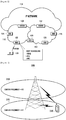
- FIG. 1 a schematic diagram illustrates an LTE mobile communication system.
- An Evolved Radio Access Network (E-RAN) 110, 112 is simplified with a two-node architecture composed of Evolved Node B's (ENBs or Node B's) 120, 122, 124, 126, 128, and Access Gateways, or Enhanced Gateway General Packet Radio Service (GPRS) Support Nodes (EGGSN) 130, 132.
- ESGSN Enhanced Gateway General Packet Radio Service
- a User Equipment (UE) 101 accesses an Internet Protocol (IP) network 114 via the E-RAN 110, 112.
- IP Internet Protocol
- the ENBs 120-128 correspond to the conventional Node B's of a Universal Mobile Telecommunications System (UMTS). Each of the ENBs 120-128 connects to the UE 101 and performs the functions of a conventional Node B.
- UMTS Universal Mobile Telecommunications System
- VoIP Voice over IP
- a resource is allocated in consideration of an amount of data to be transmitted and channel status, which differs significantly from voice communication services.
- a mobile communication system is provided with a scheduler, which manages resource allocation in consideration of the available resources, channel status, transmission data amount, and the like.
- resource scheduling is required in LTE.
- a scheduler that is incorporated into a base station is responsible for management of radio transmission resources.
- ENBs 120-128 of FIG. 1 collect status information of UEs and schedule the UEs based on the collected status information. Each ENB 120-128 controls a plurality of cells.
- LTE promises download speeds that are up to 100 Mbps. In order to achieve these high data rates, various studies have been conducted in several areas, including minimization of the number of nodes involved in the connections, simplification of network topology, and close placement of radio protocol to radio channels. LTE also uses Orthogonal Frequency Division Multiplexing (OFDM) as a radio access technology in order to achieve these transmission rates. LTE also utilizes Adaptive Modulation & Coding (AMC) in determining the modulation scheme and channel coding rate in accordance with the channel status of the UE.
- OFDM Orthogonal Frequency Division Multiplexing
- AMC Adaptive Modulation & Coding
- LTE-A LTE-Advanced
- Carrier aggregation is a technique in which multiple downlink and uplink carriers are aggregated for a mobile terminal.
- FIG. 2 is a diagram illustrating carrier aggregation in an LTE mobile communication system.
- a base station transmits and receives a plurality of carriers within different frequency bands.
- a UE 220 transmits and receives a signal and transmits data through one of the two carriers in the conventional communication system.
- the UE has carrier aggregation capability, it can be allocated more carriers to increase its transmission speed.
- the base station sends the UE an uplink transmission power control command through the downlink carrier.
- the uplink transmission power control command carries information for adjusting the transmission power of the UE and may be carried in the form of a separate control signal or by way of a transmission resource allocation signal.
- the UE In a conventional mobile communication system, the UE is allocated a single downlink carrier and a single uplink carrier. Therefore, the uplink carrier to which the uplink transmission power control command refers is clear. However, in the advanced mobile communication system described above in which a mobile terminal transmits through multiple uplink carriers, the uplink carrier to which the uplink transmission power control command refers is not clear.
- an aspect of the present invention provides a method and system for controlling uplink transmission power in a wireless communication system.
- the present invention provides a method and apparatus for controlling uplink transmission power that is capable of minimizing signaling overhead and processing load of a user equipment aggregating multiple carriers in a wireless communication system.
- a method for controlling uplink transmission power of a user equipment in a wireless communication system includes aggregating a plurality of uplink carriers into an uplink carrier group by frequency; selecting one of a plurality of downlink carriers associated with at least one of the uplink carriers of the uplink carrier group in terms of path loss; and determining transmission power of the uplink carriers based on the path loss of the selected downlink carrier.
- a user equipment for controlling uplink transmission power in a wireless communication system includes a transceiver which transmits and receives data and control signals on uplink and downlink carriers; and an uplink transmission power controller which aggregates a plurality of uplink carriers into an uplink carrier group by frequency, selects one of a plurality of downlink carriers associated with at least one of the uplink carriers of the uplink carrier group in terms of path loss, and determines transmission power of the uplink carriers based on the path loss of the selected downlink carrier.
- the present invention relates to method and devices for controlling uplink transmission power of a user equipment in a wireless communication network. Specifically, the present invention is directed to controlling uplink transmission power of a user equipment by grouping uplink component carriers and setting the uplink transmission power of the uplink component carriers in the same group using a common power control command.
- a carrier aggregation message from a base station describes a relationship between downlink component carriers and uplink component carriers.
- the uplink component carriers may be aggregated to form an uplink component carrier group.
- the downlink component carriers may also be aggregated to form a downlink component carrier group.
- the component carriers are grouped together based on carrier frequencies in close proximity to each other such that they exhibit similar transmission characteristics.
- the carrier aggregation message includes information that maps a downlink component carrier and/or downlink component carrier group to a corresponding uplink component carrier and/or uplink component carrier group.
- the uplink transmission power to be set for an uplink component carrier is based on a Transmit Power Command (TPC) and at least an amount of path loss of the downlink component carrier.
- the carrier aggregation message includes additional information for setting the uplink transmission power.
- a downlink component carrier is designated as the TPC source.
- TPCs of downlink component carriers of a downlink component carrier group are accumulated as the TPC source.
- a downlink component carrier is designated as the path loss source.
- a download component carrier for the path loss is selected according to a predetermined rule.
- the base station sends the carrier aggregation message to the user equipment.
- the user equipment in accordance with the present invention receives the carrier aggregation message and controls the uplink transmission power by applying the power control commands from the downlink component carriers to the corresponding uplink component carriers according to the mapping indicated in the carrier aggregation message.
- a diagram illustrates carrier aggregation in an LTE mobile communication system, according to an exemplary embodiment of the present invention.
- downlink carrier aggregation of the UE is referred to as Downlink Component Carrier (DL CC)
- uplink carrier aggregation is referred to as Uplink Component Carrier (UL CC).
- Uplink carriers and downlink carriers of the UE may be mapped in advance for simplicity.
- the uplink transmission power of a specific uplink carrier is indicated only by the uplink transmission power control command received through the downlink carrier mapped to the corresponding uplink carrier.
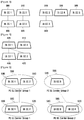
- FIG. 3 illustrates an exemplary configuration using five downlink carriers, DL CC 1 (305), DL CC 2 (310), DL CC 3 (315), DL CC 4 (320), and DL CC 5 (325), and three uplink carriers, UL CC 1 (330), UL CC 2 (335), and UL CC 3 (340).
- DL CC 1 (305) is mapped to UL CC 1 (330).
- DL CC 2 (310) is mapped to UL CC 2 (335).
- DL CC 3 (315) is mapped to UL CC 3 (340).
- the uplink transmission power control command for UL CC 1 (330) is transmitted through the DL CC 1 (305)
- the uplink transmission power control command for UL CC 2 (335) is transmitted through DL CC 2 (310)
- the uplink transmission power control command for UL CC 3 (340) is transmitted through DL CC 3 (315).
- Uplink transmission powers of uplink carriers are likely to be similar to each other when same amount of data is transmitted through the uplink carriers that are close to each other in terms of carrier frequency in an identical Modulation and Coding Scheme (MCS).
- MCS Modulation and Coding Scheme
- a method and device for controlling the uplink transmission power of multiple uplink carriers include using a single uplink transmit power control command in consideration of the above characteristics.
- FIG. 4 a diagram illustrates carrier aggregation in an LTE mobile communication system, according to another exemplary embodiment of the present invention.
- UL CC 1 (415) and UL CC 2 (420) are adjacent with or in close proximity with respect to their center frequencies.
- the uplink transmission power control of these carriers can be performed based on a single uplink transmission power control command delivered through the single DL CC 1 (405).
- uplink carriers whose transmission power can be controlled by a single uplink power control command are referred to as a Power Control Uplink Carrier Group (PC UL CG).
- PC UL CG Power Control Uplink Carrier Group
- the carriers of the PC UL CG are positioned in adjacent frequency bands, or in such close proximity, such that their uplink powers can be adjusted in the same manner by an identical uplink transmission control command, and the base station sends the UE the information to the PC UL CG using a predetermined control message.
- a Power Control Downlink Carrier Group includes one or more downlink carriers.
- An uplink transmission power control command carried through a downlink carrier included in the PC DL CG is adapted for all uplink carriers belonging to the PC UL CG mapped to the PC DL CG.
- PC DL CG 1 (550) includes DL CC 1 (505) and DL CC 2 (510).
- PC DL CG 2 (555) includes DL CC 3 (515).
- PC UL CG 1 (560) includes UL CC 1 (530) and UL CC 2 (535).
- PC UL CG 2 (565) includes UL CC 3 (540) and the UL CC 4 (520).
- PC DL CG 1 (550) is mapped to PC UL CG 1 (560) and PC DL CG 2 (555) is mapped to PC UL CG 2 (565).
- An uplink transmission power control command delivered through each of DL CC 1 (505) and DL CC 2 (510) is used for adjusting the transmission powers of UL CC 1 (530) and UL CC 2 (535) in the same manner.
- An uplink transmission power control command delivered through DL CC 3 (515) is used for adjusting the transmission powers of UL CC 3 (540) and UL CC 4 (520)in the same manner.
- the UE When a transmission power control command instructing an increase in transmission power by x dB is received through DL CC 2 (510), the UE increases the transmission power of both UL CC 1 (530) and UL CC 2 (535) by x dB. Specifically, the UE adjusts the transmission power adjustment variables of UL CC 1 (530) and UL CC 2 (535) in the same manner in accordance with the uplink transmission power control command received through DL CC 2 (510).
- the transmission power adjustment variable is a value added in a next transmission power calculation for the uplink transmission of the UE.
- an exemplary message flow diagram illustrates message flows between a network 610 and a UE 605 for carrier aggregation, according to the first exemplary embodiment of the present invention.
- the network 610 can be an ENB.
- the network 610 determines aggregation of multiple carriers for the UE 605 in accordance with the loads of the carriers and the traffic requirement status of the UE 605.
- the network 610 sends the UE 605 a control message, which includes information about the aggregated carriers.
- the carrier aggregation control message needs to aggregate both a pair of downlink carrier information and uplink carrier information because data communication of the LTE-A system is performed based on Hybrid Automatic Repeat reQuest (HARQ). Accordingly, the UE must transmit HARQ feedback information in an uplink direction after receiving downlink data, and must receive the HARQ feedback information in a downlink direction after transmitting uplink data.
- HARQ Hybrid Automatic Repeat reQuest
- the downlink/uplink carrier and the uplink/downlink carrier are correlated according to HARQ feedback.
- a predetermined rule may be implemented defining that the carrier aggregation message includes information on both the uplink and downlink carriers and the paired downlink carrier and uplink carrier correlated according to HARQ feedback.
- Downlink carrier information includes the center frequency and bandwidth of the downlink carrier.
- Uplink carrier information includes the center frequency and bandwidth of the uplink carrier.
- the control message also includes information about transmission power control of the uplink carrier, for example, information indicating the PC UL CG to which the uplink carrier belongs.
- the indication information can be an identifier uniquely assigned to the PC UL CG or an identifier uniquely assigned to an uplink carrier of which transmission power is controlled with other aggregated uplink carriers.
- the control information also can include information on the PC DL CG.
- the PC DL CG information can be an identifier of the PC DL CG composed of the downlink carriers aggregated with reference to the control message.
- the information contained in the carrier aggregation message is shown in Table 1 below.
- Table 1 Name Description > aggregated carrier information >> downlink carrier information >>> DL CC id Identifier of downlink carrier >>> Carrier Frequency Center frequency of downlink carrier >>> Bandwidth Bandwidth of downlink carrier >>> PC DL CG information Information indicating PC DL CG of downlink carriers, e.g. identifier >> uplink carrier information >>> UL CC id Identifier of uplink carrier >>> Carrier Frequency Center frequency of uplink carrier >>> Bandwidth Bandwidth of uplink carrier >>> PC UL CG information Information indicating PC UL CG of uplink carriers, e.g. identifier In Table 1, '>' indicates hierarchical level of the information. For example, the information marked with two '>' is lower than the information marked with a single '>' in hierarchical structure.
- a carrier aggregation message includes information of more than one aggregated carrier.
- the PC DL CG and the PC UL CG having the same identifier are mapped to each other, no mapping information is transmitted.
- Table 2 shows the information of the carrier aggregation message in aggregations of three downlink carriers and four uplink carriers as shown in FIG. 5 .
- carrier aggregation information > carrier aggregation information >>downlink carrier information >>downlink carrier information >>> DL CC id 1 >>> DL CC id 2 >>> Carrier Frequency f1 >>> Carrier Frequency f3 >>> Bandwidth 5 MHz >>> Bandwidth 5 MHz >>> PC DL CG information 1 >>> PC DL CG information 1 >> uplink carrier information >> uplink carrier information >>> UL CC id 1 >>> UL CC id 2 >>> Carrier Frequency f2 >>> Carrier Frequency f4 >>> Bandwidth 5 MHz >>> Bandwidth 5 MHz >>> PC UL CG information 1 >>> PC UL CG information 1 > carrier aggregation information > carrier aggregation information >>downlink carrier information >>> DL CC id 3 >>> DL CC id 3 >>> Carrier Frequency f5 >>> Carrier Frequency f5 >>> Bandwidth
- the identification of the PC DL CG can be performed using a predetermined rule defining that all downlink carriers associated with all uplink carriers belonging to a PC UL CG according to HARQ feedback constitutes the PC DL GC mapped to the PC UL CG.
- this rule is implemented the identifier of the PC DL CG does not need to be transmitted.
- the carrier aggregation message includes the information as shown in Table 3 below.
- Table 4 shows the information carried by a carrier aggregation message in an aggregation of three downlink carriers and four uplink carriers.
- carrier aggregation information > carrier aggregation information >>downlink carrier information >>downlink carrier information >>> DL CC id 1 >>> DL CC id 2 >>> Carrier Frequency f1 >>> Carrier Frequency f3 >>> Bandwidth 5 MHz >>> Bandwidth 5 MHz
- uplink carrier information >>> UL CC id 1 >>> UL CC id 2 >>> Carrier Frequency f2 >>> Carrier Frequency f4 >>> Bandwidth 5 MHz >>> Bandwidth 5 MHz >>> PC UL CG information 1 >>> PC UL CG information 1 > carrier aggregation information > carrier aggregation information >>downlink carrier information >>> DL CC id 3 >>> DL CC id 3 >>> Carrier Frequency f5 >>
- UL CC 1 and UL CC 2 belong to the same PC UL CG, and UL CC 3 and UL CC 4 belong to another PC UL CG.
- the UL CC 1 and UL CC 2 are associated with the respective DL CC 1 and DL CC 2 according to HARQ feedback, such that the transmission powers of UL CC 1 and UL CC 2 are adjusted on the basis of the uplink transmission power control commands received through DL CC 1 DL CC 2.
- UL CC 3 and UL CC 4 are associated with the respective DL CC 3 and DL CC 4 according to HARQ feedback such that the transmission powers of UL CC 3 and UL CC 4 are adjusted on the basis of the uplink transmission power control command received through DL CC 3.
- the PC UL CG information may include a reference uplink carrier identifier on behalf of the PC UL CG identifier.
- the uplink carriers assigned the same reference downlink carrier identifier can be regarded as belonging to the same PC UL CG.
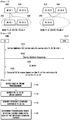
- the UE 605 when the carrier aggregation control information is received by the UE 605 at step 615 from the network 610, the UE 605 sends a response message at step 620, monitors the control channel of the aggregated downlink carriers, receives and transmits data through the aggregated downlink and uplink carriers according to the instruction of the network 610, and transmits and receives the HARQ feedback information through the uplink and downlink carriers mapped to the aggregated downlink and uplink carriers.
- the UE 605 checks the PC DL CG to which the downlink carrier belongs. The UE then adjusts the uplink transmission power of the uplink carriers belonging to the PC UL CG mapped to the PC DL CG by a value indicated by the TPC command at step 630. Specifically, the uplink transmission power variables of the uplink carriers are adjusted by the value indicated by the TPC command.
- TPC Transmission Power Control
- FIG. 7 a flowchart illustrates an exemplary transmission power adjustment methodology of a UE, according to the first exemplary embodiment of the present invention.
- a TCP is received through a downlink carrier at step 705.
- the UE identifies the PC DL CG to which the downlink carrier belongs at step 710.
- the relationship between the downlink carrier and the PC DL CG is configured by the network in the call establishment process or the carrier aggregation process.
- the UE checks the PC UL CG mapped to the PC DL CG at step 715.
- the mapping relationship between the PC DL CG and the PC UL CG is also determined by the network in the call establishment process or the carrier aggregation process.
- the UE adjusts the transmission powers of all the uplink carriers belonging to the PC UL CG by the value indicated by the TPC at step 720. Specifically, the transmission power adjustment variables of the uplink carriers are adjusted by the value indicated by the TPC.
- the UE Prior to performing uplink transmission, the UE calculates the transmission power of the uplink carriers at a predetermined time point using Equation (1) below.
- Uplink transmission power MIN P CMAX , f resource amount for uplink transmission MCS constant transmission power adjustment variable and path loss
- P CMAX denotes a maximum transmission power permitted by the network.
- f is a function that outputs an appropriate value to the input such as resource amount for uplink transmission, MCS level, and transmission power adjustment variable. The output value is in proportion of the input value in general.
- the transmission power adjustment variable can be managed per uplink carrier, and the variable is obtained by accumulating the TPCs received until a current time.
- the operations of the UE in FIG. 7 are illustrated under the assumption of the downlink carriers explicitly belonging to a PC DL CG and the uplink carriers belonging to a PC UL CG, and the explicit signaling of the control message informing the correlation between the PC DL CG and the PC UL CG.
- the relationship between the downlink and uplink carriers can be determined according to a predetermined rule.
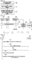
- FIG. 8 a flowchart illustrates exemplary operations of another UE, according to the first exemplary embodiment of the present invention.
- FIG. 8 shows the operations of the UE when downlink carriers are correlated with uplink carriers according to HARQ feedback.
- the UE identifies an uplink carrier correlated with the downlink carrier according to HARQ feedback and adjusts the transmission power of the identified uplink carrier by an amount indicated by the transmission power control command at step 810.
- the UE identifies other uplink carriers that are aggregated with the uplink carrier correlated with the downlink carrier and adjusts the other aggregated uplink carriers by the amount indicated by the transmission power control command at step 815.
- the other uplink carriers have an identical reference downlink carrier or belong to the same PC UL CG.
- multiple TPC commands can be received for a single uplink carrier (or for a PC UL CG).
- the UE updates the transmission power adjustment variable of the uplink carrier (or the entire PC UL CG to which the uplink carrier belongs) with the summing result of the multiple transmission power control commands.
- the path loss of the downlink carrier is considered in order to obtain the uplink power.
- the carriers may be unclear which downlink carrier is to be considered for the path loss determination in order to calculate the uplink transmission power of an uplink carrier.
- One method is to use the path loss of the downlink carrier correlated with the uplink carrier according to HARQ feedback.
- the uplink carrier is correlated with multiple downlink carriers according to HARQ feedback, it becomes difficult to determine the downlink carrier for the path loss with only the HARQ feedback.
- the relationship between the uplink carrier and the downlink carrier in which path loss is used for calculating the transmission power of the uplink carrier is indicated explicitly through the control message. For instance, when the multiple uplink carriers are positioned in adjacent frequency bands, or in close proximity thereto, the pass loss of a single downlink carrier may be used for calculating the transmission power of the uplink carriers.
- FIG. 9 a diagram illustrates an exemplary configuration of a Path Loss Uplink Carrier Group (PL UL CG), according to the second exemplary embodiment of the present invention.
- UE uses four aggregated downlink carriers, DL CC 1 (905), DL CC 2 (910), DL CC 3 (915), DL CC 4 (920), and three aggregated uplink carriers, UL CC 1 (930), UL CC 2 (935), UL CC 3 (940).
- the downlink and uplink carriers are correlated according to HARQ feedback as expressed with dotted lines as shown in FIG. 9 .
- a group of uplink carriers of which transmission powers are calculated using the path loss of a specific downlink carrier is defined as a PL UL CG as expressed with a solid line.
- the UL CC 1 (930) and the UL CC 2 (935) belong to PL UL CG 1 (945), and the UL CC 3 (940) belongs to PL UL CG 2 (950).
- the transmission power of the uplink carriers belonging to the PL UL CG 1 (945) are calculated using the path loss of the DL CC 1 (905).
- the transmission power of the uplink carriers belonging to the PL UL CG 2 (950) are calculated using the path loss of the DL CC 3 (915).
- FIG. 10 a message flow diagram illustrates exemplary message flows between a network and a UE, according to the second exemplary embodiment of the present invention.
- FIG. 10 shows message flows between a UE 1005 and a network 1010 for carrier aggregation.
- the network 1010 can be an ENB.
- the network 1010 sends messages to the UE 1005 in a manner similar to that described above with reference to FIG. 6 .
- the control message includes information on the carriers to be aggregated.
- the control message also may include information on the PL UL CG.
- the PL UL CG information includes information about the uplink carriers aggregated into the PL UL CG and the reference downlink carrier of the PL UL CG.
- the information contained in the carrier aggregation message is described as shown in Table 5. Lower level information of the carrier aggregation information is identical with those described with reference to Tables 1 and 3.
- [Table 5] Name Description > Carrier aggregation information Information on the aggregated carriers. Multiple carrier aggregation information entities can be included in a control message. > PL UL CG information Information on PL UL CG. Multiple PL UL CG entities can be included in a control message.
- Table 6 shows the information carried by an exemplary carrier aggregation message in aggregations of four downlink carriers and three uplink carriers as shown in FIG. 9 .
- Carrier aggregation information See table 2 or table 4.
- PL UL CG information >> UL CC id UL CC 1, UL CC 2 >> Reference downlink carrier DL CC 1
- PL UL CG information >> UL CC id UL CC 3 >> Reference downlink carrier DL CC 3
- the uplink transmission powers of the UL CC 1 (930) and the UL CC 2 (935) are calculated using the path loss of the DL CC 1 (905), and the uplink transmission power of the UL CC 3 (940) is calculated using the path loss of the DL CC 3 (915).
- the PL UL CG information can be included in the carrier aggregation information as shown in Table 7.
- Table 7 Name Description > Carrier aggregation information >> Downlink carrier information >>> DL CC id Downlink carrier identifier >>> Carrier Frequency Center frequency of downlink carrier >>> Bandwidth Bandwidth of downlink carrier >> Uplink carrier information >>> UL CC id Uplink carrier identifier >>> Carrier Frequency Center frequency of uplink carrier >>> Bandwidth Bandwidth of uplink carrier >>> PL UL CG information Identifier of PL UL CG including uplink carrier
- the UE can identify the uplink carriers aggregated in a PL UL CG and select a downlink carrier having the lowest center frequency among the downlink carriers correlated with the uplink carriers according to HARQ feedback as a reference carrier.
- the UE also can randomly select one of the downlink carriers correlated with the uplink carriers according to HARQ feedback. This is possible because there is no need to select a specific downlink carrier as the reference downlink carrier from the viewpoint of path loss since the path loss differences among the downlink carriers positioned adjacent to or in close proximity with each other are likely to be small.
- Table 8 shows the information carried by a exemplary carrier aggregation message in aggregations of four downlink carriers and three uplink carriers as shown in FIG. 9 .
- the UE calculates the transmission powers of UL CC 1 (930) and UL CC 2 (935) using the path loss of a downlink carrier selected in accordance with a predetermined rule among the downlink carriers correlated with the uplink carriers. For example, the UE can use the path loss of the downlink carrier having the highest center frequency or the lowest center frequency or having a path loss measurement value at the time of determining the transmission power. In this example, it is noted that the downlink carrier must be correlated with one of the uplink carriers belonged to the corresponding PL UL CG according to HARQ feedback.
- the downlink carrier of which path loss is used for determining the uplink transmission power can be explicitly indicated in the uplink carrier information as shown in Table 9.
- Table 9 Name Description > Carrier aggregation information >> Downlink carrier information >>> DL CC id Downlink carrier identifier >>> Carrier Frequency Center frequency of downlink carrier >>> Bandwidth Bandwidth of downlink carrier >> Uplink carrier information >>> UL CC id Uplink carrier identifier >>> Carrier Frequency Center frequency of uplink carrier >>> Bandwidth Bandwidth of uplink carrier >>> Reference downlink carrier information Identifier of a downlink carrier of which path loss is measured for determining transmission power of uplink carrier.
- Table 10 shows the information carried by an exemplary carrier aggregation message in aggregations of four downlink carriers and three uplink carriers as shown in FIG. 9 .
- Carrier aggregation information > Carrier aggregation information >> Downlink carrier information >>> DL CC id 1 >>> DL CC id 2 >>> Carrier Frequency f1 >>> Carrier Frequency f3 >>> Bandwidth 5 MHz >>> Bandwidth 5 MHz
- Uplink carrier information >> Uplink carrier information >>> UL CC id 1 >>> UL CC id 2 >>> Carrier Frequency f2 >>> Carrier Frequency f4 >>> Bandwidth 5 MHz >>> Bandwidth 5 MHz >>> Reference downlink carrier information 1 >>> PL UL CG information 1 > Carrier aggregation information > Carrier aggregation information >> Downlink carrier information >>> DL CC id 3 >>> DL CC id 4 >>
- the reference downlink carriers of both UL CC 1 (930) and UL CC 2 (935) are set to DL CC 1 (905) such that the UE determines the transmission powers of UL CC 1 (930) and UL CC 2 (935) using the path loss of DL CC 1 (905).
- the UE 1005 when the carrier aggregation information is received, the UE 1005 functions in a manner similar to that described above in FIG. 6 .
- the UE 1005 receives an uplink transmission resource allocation signal at step 1025, after sending the response message at step 1020.
- the uplink transmission resource allocation signal includes information related to a transmission resource and an MCS level for the uplink transmission.
- the UE 1005 identifies the PL UL CG to which the uplink carriers for the uplink transmission belongs and determines the uplink transmission power using the path loss of the reference downlink carrier of the identified PL UL CG at step 1030.
- FIG. 11 a diagram illustrates an exemplary transmission power determination methodology of a UE, according to the second exemplary embodiment of the present invention.
- the UE When an uplink transmission allocation signal for the uplink carrier is received, the UE detects a need for performing uplink transmission through one of the aggregated uplink carriers at step 1105.
- the UE identifies the PL UL CG to which the uplink carrier belongs at step 1110.
- the relationship between the uplink carrier and the PL UL CG is configured in a call establishment process or a carrier aggregation process.
- the UE identifies the reference downlink carrier of the PL UL CG at step 1115.
- the mapping relationship between the PL UL CG and the reference downlink carrier can be configured by the network in the call establishment process or carrier aggregation process, or determined by the UE according to a predetermined rule.
- the UE determines the transmission power of the uplink carrier using the path loss of the identified reference downlink carrier at step 1120.
- FIG. 12 a diagram illustrates another exemplary transmission power determination methodology of a UE, according to the second exemplary embodiment of the present invention.
- FIG. 12 shows the operations of the mobile terminal in case that the reference carrier information is included in the uplink carrier information as shown in Table 9.
- the UE detects a need for performing uplink transmission through one of the aggregated uplink carriers at step 1205.
- the UE identifies the reference downlink carrier of the uplink carrier at step 1210.
- the relationship between the uplink carrier and the reference downlink carrier may be configured in a call establishment process or a carrier aggregation process.
- the UE determines the transmission power of the uplink carrier using the path loss of the reference downlink carrier in step 1215.
- FIG. 13 a diagram illustrates an exemplary configuration of a receiving device of a UE, according to an exemplary embodiment of the present invention.
- the device includes a transceiver 1305, a TPC processor 1315, an uplink transmission power controller 1310, a multiplexer/demultiplexer 1320, a control message processor 1335, and other upper layer devices 1325 and 1330.
- the transceiver 1305 receives data and predetermined control signals via downlink carriers and transmits data and predetermined control signals via uplink carriers.
- the TPC processor 1315 analyzes a TPC command received through the downlink carrier and outputs an uplink transmission power adjustment value to the uplink transmission power controller 1310.
- the uplink transmission power controller 1310 updates the uplink transmission power adjustment variables for an uplink carrier with the uplink transmission power adjustment value provided by the TPC processor 1315.
- the uplink transmission power controller 1310 also calculates an uplink transmission power of an uplink carrier using the value stored in an uplink transmission power adjustment variable corresponding to the uplink carrier.
- the uplink transmission power controller 1310 also controls the transceiver 1305 to perform uplink transmission with the transmission power determined by the transmission power controller 1310.
- the multiplexer/demultiplexer 1320 performs multiplexing on the data output from the upper layer devices 1325 and 1330 and the control message processor 1335, performs demultiplexing on the data output by the transceiver 1305, and delivers the demultiplexed data to the upper layer devices 1325 and 1330 and/or the control message processor 1335.
- the control message processor 1335 processes the control message transmitted by the network and performs appropriate operations as described above. For example, the control message processor 1335 extracts the PC DL CG information, PC UL CG information, and/or PL UL CG information from the carrier aggregation message and sends the extracted information to the TPC processor 1315.
- the upper layer devices 1325 and 1330 can be configured for processing the data generated with the user services, such as File Transfer Protocol (FTP) or Voice over IP (VoIP), and transfers the processed user service data to the multiplexer or transfers the data demultiplexed by the demultiplexer to the upper layer service applications.
- FTP File Transfer Protocol
- VoIP Voice over IP
- the transmission power of the uplink carrier is determined in consideration of the path loss of one of a plurality of downlink carriers.
- the uplink transmission power should be determined in accordance with the channel conditions of the uplink carriers. For example, it is preferred to assign high transmission power for bad channel condition and low transmission power for good channel condition. Since the uplink channel condition cannot be measured by the UE, the UE estimates the uplink channel condition using the path loss of a downlink carrier. If there exists multiple downlink carriers of which channel conditions are similar to each other, i.e. multiple downlink carriers positioned in the same frequency band, there may be no significant difference in performance expected even when estimating the uplink channel condition using the path loss of one of the downlink carriers. If there exists a plurality of downlink carriers available for estimating the channel condition of a certain uplink carrier, it is preferred for the UE to estimate the channel condition of the uplink carrier using the downlink carrier of which channel condition can be most precisely measured.
- an uplink carrier is associated with a plurality of downlink carrier in terms of pass loss, and the UE selects one of the associated downlink carriers and determines the uplink transmission power by using the path loss of the selected downlink carrier under a predetermined rule when performing uplink transmission.
- the rule is defined such that the downlink carrier providing the most precise path loss measurement value can be selected.
- a message flow diagram illustrates exemplary message flows between a network and a UE according to the third exemplary embodiment of the present invention.
- the network 1410 can be an ENB.
- the network 1410 can determine the carrier aggregation of the UE 1405 in consideration of the loads of the carriers or the traffic condition required by the UE 1405.
- the network sends the UE 1405 a control message defined for indicating carrier aggregation at step 1415.
- the control message includes the information on the carriers to be aggregated.
- the control message can include the information on the center frequencies and bandwidths of the uplink carriers to be aggregated.
- the control message also can include a list of the downlink carriers associated, in terms of pass loss, with the aggregated uplink carriers.
- the downlink carriers associated with an uplink carrier in terms of pass loss belongs to the same frequency band and can be the downlink carriers that are already aggregated or to be aggregated soon. Association between the uplink and downlink carriers in terms of pass loss means that the path loss of the downlink carrier is considered to compute the uplink transmission power.
- the UE 1405 aggregates the carriers based on the received carrier aggregation control information and sends the network 1410 a response message at step 1420.
- the UE 1405 monitors the control channels of the aggregated downlink carriers, transmit uplink data through aggregate uplink carriers, receive downlink data through aggregated downlink carrier, and transmit and/or HARQ feedback information.
- the UE 1405 receives an uplink transmission resource allocation signal for an uplink carrier through a downlink carrier at step 1425.
- the uplink transmission resource allocation signal can includes the information on the transmission resource and MCS level for the uplink transmission.
- the UE 1405 checks which downlink carriers are associated with the uplink carrier for the uplink transmission in terms of path loss and selects one of the associated downlink carriers under a predetermined rule at step 1427.
- the UE 1405 calculates the uplink transmission power using the path loss of the selected downlink carrier at step 1430.
- the rule for selecting one of the downlink carriers associated in terms of path loss can be exemplary defined as follows.
- the downlink carriers are aggregated by means of a control message and used for transmitting and/or receiving data when a base station is activated. Accordingly, the downlink carriers aggregated for a UE can be consisted of activated downlink carriers and deactivated downlink carriers. Since the activated downlink carriers are more frequently measured, the accuracy of the channel condition of an activated downlink carrier is higher than that of the de-activated downlink carrier. For reference purpose, the channel condition is determined based on the reference signal received power, and the reference signal received power is closely related with the path loss value.
- the reference signal received power of a downlink carrier is a signal strength value of a Cell Reference Signal of the carrier.
- the RSRP measurement is performed at a predetermined interval, and the shorter the RSRP measurement interval is, the higher the measurement accuracy is.
- FIG. 15 is a flowchart illustrating an uplink transmission power control methodology according to the third embodiment of the present invention.
- the UE 1405 detects a need for performing uplink transmission through one of the aggregated uplink carriers at step 1505.
- the receipt of an uplink transmission resource allocation signal initiates the need of uplink transmission.
- the UE 1405 identifies the downlink carriers associated with the uplink carrier in terms of pass loss at step 1510.
- the downlink carriers associated with an uplink carrier is notified to the network 1410 in a call setup process or a carrier aggregation process.
- the UE 1405 selects one of the downlink carriers associated with the uplink carrier in terms of path loss at step 1515. This selection can be performed under a predetermined rule, e.g. ⁇ rule 1> or ⁇ rule 2>.
- the UE 1405 determines the uplink transmission power using the path loss of the selected downlink carrier at step 1520.
- the transmission powers of all the uplink carriers are determined using the path loss of a single downlink carrier.
- the path loss of the downlink carriers can be used to estimate the channel conditions of the uplink carriers. Since the downlink carriers and the uplink carriers are positioned in different frequency bands, it is difficult to estimate the channel condition of an uplink carrier precisely using the path loss of a downlink carrier, and thus the UE takes into account the value obtained by adding a predetermined constant to the path loss value of the downlink carrier to compensate for the difference of channel conditions caused by difference of the frequency bands.
- the base station in order for the UE to calculate the transmission powers of uplink carriers positioned in different frequency bands using the path loss of a single downlink carrier, the base station sends the UE the per-carrier compensation constants to be used for calculation of the transmission powers of the uplink carriers along in the uplink carrier aggregation request.
- the compensation constant can be determined so as to be proportional to the difference of the center frequencies of the uplink carrier and the reference downlink carrier.
- FIG. 16 a flowchart illustrates an exemplary uplink transmission power control methodology according to the fourth exemplary embodiment of the present invention.
- the UE identifiers the reference downlink carrier among the downlink carriers in the call setup process or the carrier aggregation process at step 1600.
- the reference downlink carrier is the carrier, called anchor carrier, which provides its path loss to be used for calculating the transmission powers of the uplink carriers and is always in active state.
- the UE detects a need for performing uplink transmission through one of the aggregated uplink carriers at step 1605. For example, the need of uplink transmission can be detected when an uplink transmission resource allocation signal for the uplink carrier received.
- the UE extracts the compensation value corresponding to the uplink carrier at step 1610.
- the UE receives the compensation constants corresponding to individual uplink carriers from the base station.
- the UE can obtain the compensation constants by its own calculation rather than receiving from the base station.
- each compensation constant is determined depending on the distance between the corresponding uplink carrier and the reference downlink carrier.
- the compensation constant can be determined so as to be proportional to the distance between the center frequencies of the uplink carrier and the reference downlink carrier.
- the UE determines the transmission powers of the uplink carriers using the path loss of the reference downlink carrier and the compensation constants of the uplink carriers at step 1615.
- the uplink transmission powers can be calculated using Equation (2) below.
- Uplink Transmission Power MIN P CMAX P required
- P CMAX denotes the maximum transmission power allowed by the network as in equation (1).
- the P required can be calculated using Equation (3) below.
- P required value related to resource amount to be used for uplink transmission + value related to MCS to be adopted for uplink transmission + transmission power adjustment variable + ⁇ corresponding uplink carrier ⁇ path loss of reference dowlink carrier + compensation constant of corresponding uplink carrier )
- the value related to resource amount to be used for uplink transmission is the value determined in one-to-one correspondence to the resource amount.
- the value related to MCS to be adopted for uplink transmission is the value determined in one-to-one correspondence to the MCS level.
- the compensation constant and ⁇ are the value sent per uplink carrier and used for compensation of the frequency difference between uplink and downlink carriers.
- FIG. 17 a diagram illustrates an exemplary configuration of a UE according to an exemplary embodiment of the present invention.
- the UE includes a transceiver 1705, an uplink transmission power controller 1710, a multiplexer/demultiplexer 1720, upper layer devices 1725 and 1730, and a control message processor 1735.
- the transceiver 1705 transmits and receives data and control signals through uplink and downlink carriers.
- the transceiver 1705 can receive the information on the downlink carriers associated with the uplink carriers in terms of path loss from the network and deliver the information to the control message processor 1735.
- the control message processor 1735 analyzes the information on the downlink carriers associated with the uplink carriers in terms of path loss and provides the uplink transmission power controller 1710 with the analysis result.
- the uplink transmission power controller 1710 identifiers the downlink carriers associated with the uplink carriers in terms of path loss using the information provided by the control message processor 1735.
- the uplink transmission power controller 1710 selects a downlink carrier of which path loss is to be used among the identified downlink carriers and determined the transmission powers of the uplink carriers using the path loss of the selected downlink carrier. In order to determine the transmission power of the uplink carrier, Equation (1) can be used.
- the operations of the uplink transmission power controller 1710 have been described above with reference to FIGs. 14 and 15 .
- the transceiver 1705 transmits data through the uplink carriers with the determined transmission power.
- the transceiver 1705 transmits and receives data and control signals through the uplink can downlink carriers.
- the transceiver 1705 can receive the information on the reference downlink carrier and compensation constants corresponding to the uplink carriers from the network and deliver the information to the control message processor 1735.
- the control message processor 1735 analyzes the information on the reference downlink carrier and the compensation constants corresponding to the uplink carriers and provides the uplink transmission power controller 1710 with the analysis result.
- the uplink transmission power controller 1710 identifiers the reference downlink carrier and extracts the compensation constants corresponding to the uplink carriers using the information provided by the control message processor 1735.
- the uplink transmission power controller 1710 determines the transmission powers of the uplink carriers using the path loss of the reference downlink carrier and the compensation constants of the uplink carriers.
- the transmission powers of the uplink carriers can be calculated using Equation (2) and Equation (3). The operations of the uplink transmission power controller 1710 have been described above with reference to FIG. 16 .
- the transceiver 1705 transmits data through the uplink carriers with determined transmission powers.
- Such computer program instructions can be stored in the processor of a specific computer or other programmable data processing device, and thus the instructions executed by the computer or the programmable data procession device create the means for performing the functions described above with reference to the flowcharts.
- the computer program instructions can be stored in the computer-executable or computer-readable memory for use in the computer or other programmable data processing devices to be implement in special manner such that the instructions stored the computer-usable or computer-executable memory can be fabricated in the forms of product items containing instructions means for performing the functions described with reference to the flowcharts. Since the computer instructions can be installed in a computer or other programmable data processing device, it is possible to create the processes executed in series on the computer or other programmable data processing device to provide the execution steps described with reference to the flowcharts.
- each step can be a part of a module, a segment, or a code which includes at least one executable instruction for executing specific logical function(s).
- the functions of the aforementioned steps can occur out of order. For example, two steps depicted in temporal order can be executed at the same time or in reverse order depending on the implementation.
- the term ' ⁇ unit' means a software component or a hardware component such as FPGA or ASIC.
- the term ' ⁇ unit' is not limited to the software or hardware.
- a ' ⁇ unit' can be configured so as to be in an addressable storage medium or reproduce one or more processors.
- ' ⁇ unit' includes components (such as software components, object-oriented software components, class components, and task components) and processes, functions, attributes, procedures, subroutines, segments of program code, drivers, arrays, and variables.
- the function provided along with the components within ' ⁇ unit' can be combined with other components and ' ⁇ unit' or subdivided into ' ⁇ units'.
- the components and ' ⁇ units' can be implemented to operate one or more CPUs within a device or a secure multimedia card.
- the method and apparatus for controlling uplink transmission power is advantageous to minimize the signaling overhead and processing load of the user equipment aggregating multiple carriers in a wireless communication system.
Applications Claiming Priority (4)
| Application Number | Priority Date | Filing Date | Title |
|---|---|---|---|
| US12/490,022 US9084206B2 (en) | 2009-06-23 | 2009-06-23 | Method and apparatus for controlling uplink transmission power in wireless communication system |
| KR1020100004078A KR101651494B1 (ko) | 2009-06-23 | 2010-01-15 | 이동통신 시스템에서 업링크 전송 출력을 제어하는 방법 및 장치 |
| PCT/KR2010/004067 WO2010151040A2 (fr) | 2009-06-23 | 2010-06-23 | Procédé et appareil pour réguler la puissance d'émission en liaison montante dans un système de communication sans fil |
| EP10792322.9A EP2446674B1 (fr) | 2009-06-23 | 2010-06-23 | Procédé et appareil pour réguler la puissance d'émission en liaison montante dans un système de communication sans fil |
Related Parent Applications (2)
| Application Number | Title | Priority Date | Filing Date |
|---|---|---|---|
| EP10792322.9A Division EP2446674B1 (fr) | 2009-06-23 | 2010-06-23 | Procédé et appareil pour réguler la puissance d'émission en liaison montante dans un système de communication sans fil |
| EP10792322.9A Division-Into EP2446674B1 (fr) | 2009-06-23 | 2010-06-23 | Procédé et appareil pour réguler la puissance d'émission en liaison montante dans un système de communication sans fil |
Publications (2)
| Publication Number | Publication Date |
|---|---|
| EP3445099A1 true EP3445099A1 (fr) | 2019-02-20 |
| EP3445099B1 EP3445099B1 (fr) | 2021-03-17 |
Family
ID=43354799
Family Applications (2)
| Application Number | Title | Priority Date | Filing Date |
|---|---|---|---|
| EP10792322.9A Active EP2446674B1 (fr) | 2009-06-23 | 2010-06-23 | Procédé et appareil pour réguler la puissance d'émission en liaison montante dans un système de communication sans fil |
| EP18200122.2A Active EP3445099B1 (fr) | 2009-06-23 | 2010-06-23 | Procédé et appareil de commande de puissance de transmission de liaison montante dans un système de communication sans fil |
Family Applications Before (1)
| Application Number | Title | Priority Date | Filing Date |
|---|---|---|---|
| EP10792322.9A Active EP2446674B1 (fr) | 2009-06-23 | 2010-06-23 | Procédé et appareil pour réguler la puissance d'émission en liaison montante dans un système de communication sans fil |
Country Status (7)
| Country | Link |
|---|---|
| US (2) | US9084206B2 (fr) |
| EP (2) | EP2446674B1 (fr) |
| JP (2) | JP5678051B2 (fr) |
| KR (1) | KR101651494B1 (fr) |
| CN (2) | CN105848271B (fr) |
| ES (1) | ES2701611T3 (fr) |
| WO (1) | WO2010151040A2 (fr) |
Families Citing this family (38)
| Publication number | Priority date | Publication date | Assignee | Title |
|---|---|---|---|---|
| US9622190B2 (en) | 2006-07-25 | 2017-04-11 | Google Technology Holdings LLC | Spectrum emission level variation in schedulable wireless communication terminal |
| US20080025254A1 (en) * | 2006-07-25 | 2008-01-31 | Motorola Inc | Spectrum emission level variation in schedulable wireless communication terminal |
| EP2346295B1 (fr) * | 2008-10-22 | 2015-01-07 | Sharp Kabushiki Kaisha | Appareil de station mobile, appareil de station de base et programme d'ordinateur. |
| KR101683113B1 (ko) * | 2009-08-14 | 2016-12-06 | 엘지전자 주식회사 | 상향링크 및 하향링크 멀티 캐리어를 지원하는 무선통신 시스템에 있어서, 사용자 기기와 기지국 간의 무선 통신 방법 및 상기 방법을 수행하기 위한 장치 |
| CN101998603A (zh) * | 2009-08-24 | 2011-03-30 | 中兴通讯股份有限公司 | 信干比目标值的发送/获取方法及服务无线电网络控制器 |
| US9351293B2 (en) * | 2009-09-11 | 2016-05-24 | Qualcomm Incorporated | Multiple carrier indication and downlink control information interaction |
| US9763197B2 (en) * | 2009-10-05 | 2017-09-12 | Qualcomm Incorporated | Component carrier power control in multi-carrier wireless network |
| US8451785B2 (en) * | 2009-11-09 | 2013-05-28 | Telefonaktiebolaget L M Ericsson (Publ) | Control signal aggregation in a multi-carrier WCDMA system |
| CN104079388B (zh) | 2009-12-03 | 2017-10-17 | 华为技术有限公司 | 载波聚合时反馈ack/nack信息的方法、基站和用户设备 |
| US9124406B2 (en) | 2009-12-29 | 2015-09-01 | Qualcomm Incorporated | Fallback operation for cross-carrier signaling in multi-carrier operation |
| WO2011087276A2 (fr) * | 2010-01-13 | 2011-07-21 | 엘지전자 주식회사 | Equipement d'abonné émettant un signal sur la liaison montante dans un système de communication mobile exploitant plusieurs porteuses et procédé associé |
| KR101803015B1 (ko) * | 2010-02-10 | 2017-12-01 | 주식회사 골드피크이노베이션즈 | 다수의 요소 반송파를 운영하는 무선 통신 시스템에서 업링크 동기를 설정하는 방법 및 장치 |
| KR20110093402A (ko) * | 2010-02-12 | 2011-08-18 | 주식회사 팬택 | 다수의 요소 반송파를 운영하는 무선 통신 시스템에서 업링크 동기를 설정하는 방법 및 장치 |
| CN102208967B (zh) * | 2010-03-31 | 2014-04-09 | 中兴通讯股份有限公司 | 一种lte终端非自适应重传功率控制的方法及装置 |
| CN105897388B (zh) * | 2010-03-31 | 2019-10-18 | 华为技术有限公司 | 用于通信的方法和装置 |
| CN102724672B (zh) * | 2011-03-29 | 2017-02-08 | 中兴通讯股份有限公司 | 数据传输方法及装置 |
| US9565655B2 (en) | 2011-04-13 | 2017-02-07 | Google Technology Holdings LLC | Method and apparatus to detect the transmission bandwidth configuration of a channel in connection with reducing interference between channels in wireless communication systems |
| US8934500B2 (en) | 2011-04-13 | 2015-01-13 | Motorola Mobility Llc | Method and apparatus using two radio access technologies for scheduling resources in wireless communication systems |
| GB2479076C (en) * | 2011-05-03 | 2014-08-13 | Broadcom Corp | Uplink transmission power control mechanism |
| JP5954434B2 (ja) * | 2012-01-24 | 2016-07-20 | 日本電気株式会社 | 無線基地局及び無線基地局の制御方法 |
| GB2498758B (en) | 2012-01-26 | 2014-02-19 | Broadcom Corp | Power control |
| GB2502064B (en) * | 2012-05-14 | 2014-04-09 | Broadcom Corp | Power control |
| EP2880904B1 (fr) * | 2012-08-02 | 2017-10-25 | Telefonaktiebolaget LM Ericsson (publ) | Attribution de ressources et transmission conjointe |
| CN103929800B (zh) * | 2013-01-11 | 2017-09-29 | 电信科学技术研究院 | 一种pucch功率控制方法及装置 |
| CN104185261A (zh) | 2013-05-28 | 2014-12-03 | 索尼公司 | 用于在无线通信系统中进行无线通信的方法、装置和系统 |
| CN104427604B (zh) * | 2013-08-28 | 2018-10-12 | 上海诺基亚贝尔股份有限公司 | 一种用于分配上行功率的方法和设备 |
| US9788325B2 (en) * | 2016-03-01 | 2017-10-10 | Wipro Limited | Methods and systems for radio carriers management in a wireless broadband network |
| US10278088B2 (en) * | 2016-07-22 | 2019-04-30 | Qualcomm Incorporated | Channel estimation enhancement |
| CN108207023B (zh) * | 2016-12-18 | 2020-12-29 | 上海朗帛通信技术有限公司 | 一种用于窄带通信的ue、基站中的方法和装置 |
| JP7121659B2 (ja) * | 2016-12-20 | 2022-08-18 | シャープ株式会社 | 端末装置、基地局装置、および、通信方法 |
| CN108270532B (zh) * | 2016-12-30 | 2021-05-18 | 华为技术有限公司 | 一种信息传输方法、接入网设备及终端 |
| CN108810944B (zh) * | 2017-05-04 | 2021-04-20 | 华为技术有限公司 | 上行载波切换的方法、网络设备和终端设备 |
| CN108811063B (zh) * | 2017-05-05 | 2023-07-18 | 华为技术有限公司 | 一种确定上行信号发射功率的方法及设备 |
| CA3066916C (fr) * | 2017-06-16 | 2022-06-14 | Guangdong Oppo Mobile Telecommunications Corp., Ltd. | Procede de commande de puissance pour liaison et produit associe |
| US11368255B2 (en) * | 2017-07-28 | 2022-06-21 | Beijing Xiaomi Mobile Software Co., Ltd. | Hybrid automatic repeat request result feedback method and device |
| CN109600826A (zh) * | 2017-09-30 | 2019-04-09 | 华为技术有限公司 | 功率控制方法及装置 |
| CN109729577A (zh) * | 2017-10-27 | 2019-05-07 | 成都鼎桥通信技术有限公司 | 非对称上行载波聚合的功率控制命令字指示方法及设备 |
| US11057882B1 (en) * | 2018-04-03 | 2021-07-06 | T-Mobile Innovations Llc | Systems and methods for dynamically setting frame configuration in a wireless network |
Citations (2)
| Publication number | Priority date | Publication date | Assignee | Title |
|---|---|---|---|---|
| US20080188260A1 (en) * | 2007-02-02 | 2008-08-07 | Motorola, Inc. | Method and apparatus for uplink power control in a communication system |
| WO2008108227A1 (fr) * | 2007-03-01 | 2008-09-12 | Ntt Docomo, Inc. | Dispositif station de base et procédé de commande d'une communication |
Family Cites Families (17)
| Publication number | Priority date | Publication date | Assignee | Title |
|---|---|---|---|---|
| JPH08256102A (ja) * | 1995-01-19 | 1996-10-01 | Sony Corp | セルラーシステム |
| DE19823373A1 (de) * | 1998-05-18 | 1999-12-09 | Bosch Gmbh Robert | Radaufhängungs-Tester |
| SE9802335D0 (sv) * | 1998-06-30 | 1998-06-30 | Siemens Elema Ab | Andningshjälpsystem |
| EP1367739A1 (fr) | 2002-05-29 | 2003-12-03 | Siemens Aktiengesellschaft | Procédé de commande de la puissance d'émission dans un système radio à porteuses multiples |
| KR100735277B1 (ko) * | 2003-07-30 | 2007-07-03 | 삼성전자주식회사 | 광대역 무선 접속 통신 시스템에서 레인징 방법 |
| US8687607B2 (en) * | 2003-10-08 | 2014-04-01 | Qualcomm Incorporated | Method and apparatus for feedback reporting in a wireless communications system |
| US8897828B2 (en) | 2004-08-12 | 2014-11-25 | Intellectual Ventures Holding 81 Llc | Power control in a wireless communication system |
| US8023955B2 (en) * | 2005-08-22 | 2011-09-20 | Sony Corporation | Uplink resource allocation to control intercell interference in a wireless communication system |
| KR100983285B1 (ko) * | 2005-09-21 | 2010-09-24 | 엘지전자 주식회사 | 다중 반송파 무선 네트워크에서 복수의 역방향 피드백채널을 다중화하는 방법 및 장치 |
| US8274952B2 (en) * | 2006-10-10 | 2012-09-25 | Alcatel Lucent | Transmission power management |
| US8437792B2 (en) * | 2007-02-14 | 2013-05-07 | Qualcomm Incorporated | Uplink power control for LTE |
| CN101340711B (zh) * | 2007-07-06 | 2012-05-23 | 中兴通讯股份有限公司 | 多载波增强上行接入系统的调度信息上报方法 |
| US8724636B2 (en) * | 2008-03-31 | 2014-05-13 | Qualcomm Incorporated | Methods of reliably sending control signal |
| US8150478B2 (en) * | 2008-07-16 | 2012-04-03 | Marvell World Trade Ltd. | Uplink power control in aggregated spectrum systems |
| WO2010091425A2 (fr) | 2009-02-09 | 2010-08-12 | Interdigital Patent Holdings, Inc. | Appareil et procédé de commande de puissance de liaison montante pour une unité de réception/émission sans fil utilisant des porteuses multiples |
| US8437798B2 (en) * | 2009-04-27 | 2013-05-07 | Motorola Mobility Llc | Uplink scheduling support in multi-carrier wireless communication systems |
| US9585108B2 (en) * | 2009-05-04 | 2017-02-28 | Qualcomm Incorporated | Method and apparatus for uplink power control in a multicarrier wireless communication system |
-
2009
- 2009-06-23 US US12/490,022 patent/US9084206B2/en active Active
-
2010
- 2010-01-15 KR KR1020100004078A patent/KR101651494B1/ko active IP Right Grant
- 2010-06-23 EP EP10792322.9A patent/EP2446674B1/fr active Active
- 2010-06-23 CN CN201610362090.8A patent/CN105848271B/zh active Active
- 2010-06-23 CN CN201080028168.3A patent/CN102804872B/zh active Active
- 2010-06-23 EP EP18200122.2A patent/EP3445099B1/fr active Active
- 2010-06-23 ES ES10792322T patent/ES2701611T3/es active Active
- 2010-06-23 JP JP2012517379A patent/JP5678051B2/ja active Active
- 2010-06-23 WO PCT/KR2010/004067 patent/WO2010151040A2/fr active Application Filing
-
2014
- 2014-12-10 US US14/566,036 patent/US9629103B2/en active Active
-
2015
- 2015-01-05 JP JP2015000425A patent/JP6054433B2/ja active Active
Patent Citations (3)
| Publication number | Priority date | Publication date | Assignee | Title |
|---|---|---|---|---|
| US20080188260A1 (en) * | 2007-02-02 | 2008-08-07 | Motorola, Inc. | Method and apparatus for uplink power control in a communication system |
| WO2008108227A1 (fr) * | 2007-03-01 | 2008-09-12 | Ntt Docomo, Inc. | Dispositif station de base et procédé de commande d'une communication |
| EP2129140A1 (fr) * | 2007-03-01 | 2009-12-02 | NTT DoCoMo, Inc. | Dispositif station de base et procédé de commande d'une communication |
Also Published As
| Publication number | Publication date |
|---|---|
| WO2010151040A3 (fr) | 2011-03-31 |
| US9629103B2 (en) | 2017-04-18 |
| CN105848271B (zh) | 2020-04-10 |
| US9084206B2 (en) | 2015-07-14 |
| EP2446674B1 (fr) | 2018-11-21 |
| EP2446674A2 (fr) | 2012-05-02 |
| US20100323744A1 (en) | 2010-12-23 |
| KR20100138723A (ko) | 2010-12-31 |
| KR101651494B1 (ko) | 2016-09-05 |
| JP2012531795A (ja) | 2012-12-10 |
| CN102804872B (zh) | 2016-07-06 |
| EP3445099B1 (fr) | 2021-03-17 |
| EP2446674A4 (fr) | 2014-12-10 |
| JP5678051B2 (ja) | 2015-02-25 |
| WO2010151040A2 (fr) | 2010-12-29 |
| ES2701611T3 (es) | 2019-02-25 |
| CN102804872A (zh) | 2012-11-28 |
| JP2015092735A (ja) | 2015-05-14 |
| CN105848271A (zh) | 2016-08-10 |
| US20150094115A1 (en) | 2015-04-02 |
| JP6054433B2 (ja) | 2016-12-27 |
Similar Documents
| Publication | Publication Date | Title |
|---|---|---|
| EP3445099B1 (fr) | Procédé et appareil de commande de puissance de transmission de liaison montante dans un système de communication sans fil | |
| CN110572873B (zh) | 支持载波聚合的移动通信系统的功率余量报告方法和装置 | |
| US8249091B2 (en) | Power headroom reporting method and device for wireless communication system | |
| US9467955B2 (en) | Power headroom report method and apparatus for mobile communication system supporting carrier aggregation | |
| KR101740366B1 (ko) | 이동 통신 시스템에서 역방향 최대 전송 전력을 보고하는 방법 및 장치 | |
| EP2603992B1 (fr) | Procédé et appareil de signalement d'informations de marge de puissance dans un système de communication mobile acceptant l'agrégation de porteuses | |
| US10728859B2 (en) | Method and apparatus for determining maximum transmission power per carrier in mobile communication system supporting carrier aggregation | |
| US9730167B2 (en) | Method and apparatus for reporting power headroom information in mobile communication system supporting carrier aggregation | |
| AU2011324155A1 (en) | Uplink scheduling apparatus and method based on uplink report in wireless communication system | |
| US9736797B2 (en) | Method and apparatus for reporting power headroom information in mobile communication system supporting carrier aggregation | |
| AU2011314509B2 (en) | Method and apparatus for determining maximum transmission power per carrier in mobile communication system supporting carrier aggregation |
Legal Events
| Date | Code | Title | Description |
|---|---|---|---|
| PUAI | Public reference made under article 153(3) epc to a published international application that has entered the european phase |
Free format text: ORIGINAL CODE: 0009012 |
|
| STAA | Information on the status of an ep patent application or granted ep patent |
Free format text: STATUS: THE APPLICATION HAS BEEN PUBLISHED |
|
| AC | Divisional application: reference to earlier application |
Ref document number: 2446674 Country of ref document: EP Kind code of ref document: P |
|
| AK | Designated contracting states |
Kind code of ref document: A1 Designated state(s): AL AT BE BG CH CY CZ DE DK EE ES FI FR GB GR HR HU IE IS IT LI LT LU LV MC MK MT NL NO PL PT RO SE SI SK SM TR |
|
| STAA | Information on the status of an ep patent application or granted ep patent |
Free format text: STATUS: REQUEST FOR EXAMINATION WAS MADE |
|
| 17P | Request for examination filed |
Effective date: 20190515 |
|
| RBV | Designated contracting states (corrected) |
Designated state(s): AL AT BE BG CH CY CZ DE DK EE ES FI FR GB GR HR HU IE IS IT LI LT LU LV MC MK MT NL NO PL PT RO SE SI SK SM TR |
|
| RIC1 | Information provided on ipc code assigned before grant |
Ipc: H04W 52/34 20090101ALI20200824BHEP Ipc: H04W 52/14 20090101ALI20200824BHEP Ipc: H04W 52/24 20090101AFI20200824BHEP Ipc: H04W 52/10 20090101ALN20200824BHEP Ipc: H04W 52/16 20090101ALN20200824BHEP Ipc: H04W 52/06 20090101ALI20200824BHEP Ipc: H04W 52/28 20090101ALI20200824BHEP |
|
| GRAP | Despatch of communication of intention to grant a patent |
Free format text: ORIGINAL CODE: EPIDOSNIGR1 |
|
| STAA | Information on the status of an ep patent application or granted ep patent |
Free format text: STATUS: GRANT OF PATENT IS INTENDED |
|
| RIC1 | Information provided on ipc code assigned before grant |
Ipc: H04W 52/34 20090101ALI20200909BHEP Ipc: H04W 52/28 20090101ALI20200909BHEP Ipc: H04W 52/16 20090101ALN20200909BHEP Ipc: H04W 52/06 20090101ALI20200909BHEP Ipc: H04W 52/10 20090101ALN20200909BHEP Ipc: H04W 52/14 20090101ALI20200909BHEP Ipc: H04W 52/24 20090101AFI20200909BHEP |
|
| RIC1 | Information provided on ipc code assigned before grant |
Ipc: H04W 52/06 20090101ALI20200917BHEP Ipc: H04W 52/16 20090101ALN20200917BHEP Ipc: H04W 52/10 20090101ALN20200917BHEP Ipc: H04W 52/14 20090101ALI20200917BHEP Ipc: H04W 52/24 20090101AFI20200917BHEP Ipc: H04W 52/34 20090101ALI20200917BHEP Ipc: H04W 52/28 20090101ALI20200917BHEP |
|
| INTG | Intention to grant announced |
Effective date: 20201006 |
|
| GRAS | Grant fee paid |
Free format text: ORIGINAL CODE: EPIDOSNIGR3 |
|
| GRAA | (expected) grant |
Free format text: ORIGINAL CODE: 0009210 |
|
| STAA | Information on the status of an ep patent application or granted ep patent |
Free format text: STATUS: THE PATENT HAS BEEN GRANTED |
|
| AC | Divisional application: reference to earlier application |
Ref document number: 2446674 Country of ref document: EP Kind code of ref document: P |
|
| AK | Designated contracting states |
Kind code of ref document: B1 Designated state(s): AL AT BE BG CH CY CZ DE DK EE ES FI FR GB GR HR HU IE IS IT LI LT LU LV MC MK MT NL NO PL PT RO SE SI SK SM TR |
|
| REG | Reference to a national code |
Ref country code: GB Ref legal event code: FG4D |
|
| REG | Reference to a national code |
Ref country code: CH Ref legal event code: EP |
|
| REG | Reference to a national code |
Ref country code: DE Ref legal event code: R096 Ref document number: 602010066633 Country of ref document: DE |
|
| REG | Reference to a national code |
Ref country code: IE Ref legal event code: FG4D |
|
| REG | Reference to a national code |
Ref country code: AT Ref legal event code: REF Ref document number: 1373450 Country of ref document: AT Kind code of ref document: T Effective date: 20210415 |
|
| REG | Reference to a national code |
Ref country code: NL Ref legal event code: FP |
|
| REG | Reference to a national code |
Ref country code: LT Ref legal event code: MG9D |
|
| PG25 | Lapsed in a contracting state [announced via postgrant information from national office to epo] |
Ref country code: NO Free format text: LAPSE BECAUSE OF FAILURE TO SUBMIT A TRANSLATION OF THE DESCRIPTION OR TO PAY THE FEE WITHIN THE PRESCRIBED TIME-LIMIT Effective date: 20210617 Ref country code: BG Free format text: LAPSE BECAUSE OF FAILURE TO SUBMIT A TRANSLATION OF THE DESCRIPTION OR TO PAY THE FEE WITHIN THE PRESCRIBED TIME-LIMIT Effective date: 20210617 Ref country code: HR Free format text: LAPSE BECAUSE OF FAILURE TO SUBMIT A TRANSLATION OF THE DESCRIPTION OR TO PAY THE FEE WITHIN THE PRESCRIBED TIME-LIMIT Effective date: 20210317 Ref country code: GR Free format text: LAPSE BECAUSE OF FAILURE TO SUBMIT A TRANSLATION OF THE DESCRIPTION OR TO PAY THE FEE WITHIN THE PRESCRIBED TIME-LIMIT Effective date: 20210618 Ref country code: FI Free format text: LAPSE BECAUSE OF FAILURE TO SUBMIT A TRANSLATION OF THE DESCRIPTION OR TO PAY THE FEE WITHIN THE PRESCRIBED TIME-LIMIT Effective date: 20210317 |
|
| REG | Reference to a national code |
Ref country code: AT Ref legal event code: MK05 Ref document number: 1373450 Country of ref document: AT Kind code of ref document: T Effective date: 20210317 |
|
| PG25 | Lapsed in a contracting state [announced via postgrant information from national office to epo] |
Ref country code: LV Free format text: LAPSE BECAUSE OF FAILURE TO SUBMIT A TRANSLATION OF THE DESCRIPTION OR TO PAY THE FEE WITHIN THE PRESCRIBED TIME-LIMIT Effective date: 20210317 Ref country code: SE Free format text: LAPSE BECAUSE OF FAILURE TO SUBMIT A TRANSLATION OF THE DESCRIPTION OR TO PAY THE FEE WITHIN THE PRESCRIBED TIME-LIMIT Effective date: 20210317 |
|
| PG25 | Lapsed in a contracting state [announced via postgrant information from national office to epo] |
Ref country code: CZ Free format text: LAPSE BECAUSE OF FAILURE TO SUBMIT A TRANSLATION OF THE DESCRIPTION OR TO PAY THE FEE WITHIN THE PRESCRIBED TIME-LIMIT Effective date: 20210317 Ref country code: EE Free format text: LAPSE BECAUSE OF FAILURE TO SUBMIT A TRANSLATION OF THE DESCRIPTION OR TO PAY THE FEE WITHIN THE PRESCRIBED TIME-LIMIT Effective date: 20210317 Ref country code: LT Free format text: LAPSE BECAUSE OF FAILURE TO SUBMIT A TRANSLATION OF THE DESCRIPTION OR TO PAY THE FEE WITHIN THE PRESCRIBED TIME-LIMIT Effective date: 20210317 Ref country code: SM Free format text: LAPSE BECAUSE OF FAILURE TO SUBMIT A TRANSLATION OF THE DESCRIPTION OR TO PAY THE FEE WITHIN THE PRESCRIBED TIME-LIMIT Effective date: 20210317 Ref country code: AT Free format text: LAPSE BECAUSE OF FAILURE TO SUBMIT A TRANSLATION OF THE DESCRIPTION OR TO PAY THE FEE WITHIN THE PRESCRIBED TIME-LIMIT Effective date: 20210317 |
|
| PG25 | Lapsed in a contracting state [announced via postgrant information from national office to epo] |
Ref country code: IS Free format text: LAPSE BECAUSE OF FAILURE TO SUBMIT A TRANSLATION OF THE DESCRIPTION OR TO PAY THE FEE WITHIN THE PRESCRIBED TIME-LIMIT Effective date: 20210717 Ref country code: PT Free format text: LAPSE BECAUSE OF FAILURE TO SUBMIT A TRANSLATION OF THE DESCRIPTION OR TO PAY THE FEE WITHIN THE PRESCRIBED TIME-LIMIT Effective date: 20210719 Ref country code: PL Free format text: LAPSE BECAUSE OF FAILURE TO SUBMIT A TRANSLATION OF THE DESCRIPTION OR TO PAY THE FEE WITHIN THE PRESCRIBED TIME-LIMIT Effective date: 20210317 Ref country code: RO Free format text: LAPSE BECAUSE OF FAILURE TO SUBMIT A TRANSLATION OF THE DESCRIPTION OR TO PAY THE FEE WITHIN THE PRESCRIBED TIME-LIMIT Effective date: 20210317 Ref country code: SK Free format text: LAPSE BECAUSE OF FAILURE TO SUBMIT A TRANSLATION OF THE DESCRIPTION OR TO PAY THE FEE WITHIN THE PRESCRIBED TIME-LIMIT Effective date: 20210317 |
|
| REG | Reference to a national code |
Ref country code: DE Ref legal event code: R097 Ref document number: 602010066633 Country of ref document: DE |
|
| PLBE | No opposition filed within time limit |
Free format text: ORIGINAL CODE: 0009261 |
|
| STAA | Information on the status of an ep patent application or granted ep patent |
Free format text: STATUS: NO OPPOSITION FILED WITHIN TIME LIMIT |
|
| PG25 | Lapsed in a contracting state [announced via postgrant information from national office to epo] |
Ref country code: ES Free format text: LAPSE BECAUSE OF FAILURE TO SUBMIT A TRANSLATION OF THE DESCRIPTION OR TO PAY THE FEE WITHIN THE PRESCRIBED TIME-LIMIT Effective date: 20210317 Ref country code: DK Free format text: LAPSE BECAUSE OF FAILURE TO SUBMIT A TRANSLATION OF THE DESCRIPTION OR TO PAY THE FEE WITHIN THE PRESCRIBED TIME-LIMIT Effective date: 20210317 Ref country code: AL Free format text: LAPSE BECAUSE OF FAILURE TO SUBMIT A TRANSLATION OF THE DESCRIPTION OR TO PAY THE FEE WITHIN THE PRESCRIBED TIME-LIMIT Effective date: 20210317 Ref country code: MC Free format text: LAPSE BECAUSE OF FAILURE TO SUBMIT A TRANSLATION OF THE DESCRIPTION OR TO PAY THE FEE WITHIN THE PRESCRIBED TIME-LIMIT Effective date: 20210317 |
|
| REG | Reference to a national code |
Ref country code: CH Ref legal event code: PL |
|
| 26N | No opposition filed |
Effective date: 20211220 |
|
| PG25 | Lapsed in a contracting state [announced via postgrant information from national office to epo] |
Ref country code: SI Free format text: LAPSE BECAUSE OF FAILURE TO SUBMIT A TRANSLATION OF THE DESCRIPTION OR TO PAY THE FEE WITHIN THE PRESCRIBED TIME-LIMIT Effective date: 20210317 |
|
| REG | Reference to a national code |
Ref country code: BE Ref legal event code: MM Effective date: 20210630 |
|
| PG25 | Lapsed in a contracting state [announced via postgrant information from national office to epo] |
Ref country code: LU Free format text: LAPSE BECAUSE OF NON-PAYMENT OF DUE FEES Effective date: 20210623 |
|
| PG25 | Lapsed in a contracting state [announced via postgrant information from national office to epo] |
Ref country code: LI Free format text: LAPSE BECAUSE OF NON-PAYMENT OF DUE FEES Effective date: 20210630 Ref country code: IE Free format text: LAPSE BECAUSE OF NON-PAYMENT OF DUE FEES Effective date: 20210623 Ref country code: CH Free format text: LAPSE BECAUSE OF NON-PAYMENT OF DUE FEES Effective date: 20210630 |
|
| PG25 | Lapsed in a contracting state [announced via postgrant information from national office to epo] |
Ref country code: IS Free format text: LAPSE BECAUSE OF FAILURE TO SUBMIT A TRANSLATION OF THE DESCRIPTION OR TO PAY THE FEE WITHIN THE PRESCRIBED TIME-LIMIT Effective date: 20210717 |
|
| PG25 | Lapsed in a contracting state [announced via postgrant information from national office to epo] |
Ref country code: BE Free format text: LAPSE BECAUSE OF NON-PAYMENT OF DUE FEES Effective date: 20210630 |
|
| PG25 | Lapsed in a contracting state [announced via postgrant information from national office to epo] |
Ref country code: CY Free format text: LAPSE BECAUSE OF FAILURE TO SUBMIT A TRANSLATION OF THE DESCRIPTION OR TO PAY THE FEE WITHIN THE PRESCRIBED TIME-LIMIT Effective date: 20210317 |
|
| PG25 | Lapsed in a contracting state [announced via postgrant information from national office to epo] |
Ref country code: HU Free format text: LAPSE BECAUSE OF FAILURE TO SUBMIT A TRANSLATION OF THE DESCRIPTION OR TO PAY THE FEE WITHIN THE PRESCRIBED TIME-LIMIT; INVALID AB INITIO Effective date: 20100623 |
|
| PGFP | Annual fee paid to national office [announced via postgrant information from national office to epo] |
Ref country code: NL Payment date: 20230523 Year of fee payment: 14 Ref country code: IT Payment date: 20230523 Year of fee payment: 14 Ref country code: FR Payment date: 20230522 Year of fee payment: 14 Ref country code: DE Payment date: 20230522 Year of fee payment: 14 |
|
| PGFP | Annual fee paid to national office [announced via postgrant information from national office to epo] |
Ref country code: GB Payment date: 20230523 Year of fee payment: 14 |