EP3444621B1 - Verfahren und vorrichtung zur erkennung eines blitzeinschlags - Google Patents
Verfahren und vorrichtung zur erkennung eines blitzeinschlags Download PDFInfo
- Publication number
- EP3444621B1 EP3444621B1 EP18199445.0A EP18199445A EP3444621B1 EP 3444621 B1 EP3444621 B1 EP 3444621B1 EP 18199445 A EP18199445 A EP 18199445A EP 3444621 B1 EP3444621 B1 EP 3444621B1
- Authority
- EP
- European Patent Office
- Prior art keywords
- transistor
- current
- lightning strike
- circuit
- capacitor
- Prior art date
- Legal status (The legal status is an assumption and is not a legal conclusion. Google has not performed a legal analysis and makes no representation as to the accuracy of the status listed.)
- Active
Links
- 238000000034 method Methods 0.000 title claims description 21
- 239000003990 capacitor Substances 0.000 claims description 21
- 238000001514 detection method Methods 0.000 claims description 20
- 238000012544 monitoring process Methods 0.000 claims description 13
- 230000008859 change Effects 0.000 claims description 11
- 238000004891 communication Methods 0.000 claims description 6
- 230000001939 inductive effect Effects 0.000 claims description 4
- 229910000859 α-Fe Inorganic materials 0.000 description 11
- 239000002131 composite material Substances 0.000 description 5
- 230000006870 function Effects 0.000 description 3
- 238000012423 maintenance Methods 0.000 description 3
- 238000012360 testing method Methods 0.000 description 3
- 238000004804 winding Methods 0.000 description 3
- XEEYBQQBJWHFJM-UHFFFAOYSA-N Iron Chemical compound [Fe] XEEYBQQBJWHFJM-UHFFFAOYSA-N 0.000 description 2
- UQSXHKLRYXJYBZ-UHFFFAOYSA-N Iron oxide Chemical compound [Fe]=O UQSXHKLRYXJYBZ-UHFFFAOYSA-N 0.000 description 2
- 230000008901 benefit Effects 0.000 description 2
- 239000004020 conductor Substances 0.000 description 2
- 230000005669 field effect Effects 0.000 description 2
- 239000000463 material Substances 0.000 description 2
- 239000002184 metal Substances 0.000 description 2
- 229910052751 metal Inorganic materials 0.000 description 2
- 229910044991 metal oxide Inorganic materials 0.000 description 2
- 150000004706 metal oxides Chemical class 0.000 description 2
- 238000012545 processing Methods 0.000 description 2
- 230000001681 protective effect Effects 0.000 description 2
- 239000004065 semiconductor Substances 0.000 description 2
- 230000000740 bleeding effect Effects 0.000 description 1
- 239000000919 ceramic Substances 0.000 description 1
- 230000000295 complement effect Effects 0.000 description 1
- 238000012790 confirmation Methods 0.000 description 1
- 238000010276 construction Methods 0.000 description 1
- 230000000694 effects Effects 0.000 description 1
- 239000004744 fabric Substances 0.000 description 1
- 230000003100 immobilizing effect Effects 0.000 description 1
- 229910052742 iron Inorganic materials 0.000 description 1
- 230000002045 lasting effect Effects 0.000 description 1
- 230000000116 mitigating effect Effects 0.000 description 1
- 230000037361 pathway Effects 0.000 description 1
- 230000035699 permeability Effects 0.000 description 1
- 238000001556 precipitation Methods 0.000 description 1
- 230000002265 prevention Effects 0.000 description 1
- 238000011084 recovery Methods 0.000 description 1
- 230000009467 reduction Effects 0.000 description 1
- 230000035945 sensitivity Effects 0.000 description 1
- 230000003068 static effect Effects 0.000 description 1
- 238000013519 translation Methods 0.000 description 1
- 230000001960 triggered effect Effects 0.000 description 1
- 230000000007 visual effect Effects 0.000 description 1
Images


Classifications
-
- G—PHYSICS
- G01—MEASURING; TESTING
- G01R—MEASURING ELECTRIC VARIABLES; MEASURING MAGNETIC VARIABLES
- G01R15/00—Details of measuring arrangements of the types provided for in groups G01R17/00 - G01R29/00, G01R33/00 - G01R33/26 or G01R35/00
- G01R15/14—Adaptations providing voltage or current isolation, e.g. for high-voltage or high-current networks
- G01R15/18—Adaptations providing voltage or current isolation, e.g. for high-voltage or high-current networks using inductive devices, e.g. transformers
- G01R15/183—Adaptations providing voltage or current isolation, e.g. for high-voltage or high-current networks using inductive devices, e.g. transformers using transformers with a magnetic core
-
- B—PERFORMING OPERATIONS; TRANSPORTING
- B64—AIRCRAFT; AVIATION; COSMONAUTICS
- B64D—EQUIPMENT FOR FITTING IN OR TO AIRCRAFT; FLIGHT SUITS; PARACHUTES; ARRANGEMENT OR MOUNTING OF POWER PLANTS OR PROPULSION TRANSMISSIONS IN AIRCRAFT
- B64D45/00—Aircraft indicators or protectors not otherwise provided for
- B64D45/02—Lightning protectors; Static dischargers
-
- G—PHYSICS
- G01—MEASURING; TESTING
- G01R—MEASURING ELECTRIC VARIABLES; MEASURING MAGNETIC VARIABLES
- G01R19/00—Arrangements for measuring currents or voltages or for indicating presence or sign thereof
- G01R19/165—Indicating that current or voltage is either above or below a predetermined value or within or outside a predetermined range of values
- G01R19/16504—Indicating that current or voltage is either above or below a predetermined value or within or outside a predetermined range of values characterised by the components employed
- G01R19/16519—Indicating that current or voltage is either above or below a predetermined value or within or outside a predetermined range of values characterised by the components employed using FET's
-
- G—PHYSICS
- G01—MEASURING; TESTING
- G01R—MEASURING ELECTRIC VARIABLES; MEASURING MAGNETIC VARIABLES
- G01R31/00—Arrangements for testing electric properties; Arrangements for locating electric faults; Arrangements for electrical testing characterised by what is being tested not provided for elsewhere
- G01R31/005—Testing of electric installations on transport means
- G01R31/008—Testing of electric installations on transport means on air- or spacecraft, railway rolling stock or sea-going vessels
-
- H—ELECTRICITY
- H02—GENERATION; CONVERSION OR DISTRIBUTION OF ELECTRIC POWER
- H02G—INSTALLATION OF ELECTRIC CABLES OR LINES, OR OF COMBINED OPTICAL AND ELECTRIC CABLES OR LINES
- H02G13/00—Installations of lightning conductors; Fastening thereof to supporting structure
-
- H—ELECTRICITY
- H02—GENERATION; CONVERSION OR DISTRIBUTION OF ELECTRIC POWER
- H02H—EMERGENCY PROTECTIVE CIRCUIT ARRANGEMENTS
- H02H3/00—Emergency protective circuit arrangements for automatic disconnection directly responsive to an undesired change from normal electric working condition with or without subsequent reconnection ; integrated protection
- H02H3/20—Emergency protective circuit arrangements for automatic disconnection directly responsive to an undesired change from normal electric working condition with or without subsequent reconnection ; integrated protection responsive to excess voltage
- H02H3/22—Emergency protective circuit arrangements for automatic disconnection directly responsive to an undesired change from normal electric working condition with or without subsequent reconnection ; integrated protection responsive to excess voltage of short duration, e.g. lightning
-
- G—PHYSICS
- G01—MEASURING; TESTING
- G01R—MEASURING ELECTRIC VARIABLES; MEASURING MAGNETIC VARIABLES
- G01R29/00—Arrangements for measuring or indicating electric quantities not covered by groups G01R19/00 - G01R27/00
- G01R29/08—Measuring electromagnetic field characteristics
- G01R29/0807—Measuring electromagnetic field characteristics characterised by the application
- G01R29/0814—Field measurements related to measuring influence on or from apparatus, components or humans, e.g. in ESD, EMI, EMC, EMP testing, measuring radiation leakage; detecting presence of micro- or radiowave emitters; dosimetry; testing shielding; measurements related to lightning
- G01R29/0842—Measurements related to lightning, e.g. measuring electric disturbances, warning systems
-
- Y—GENERAL TAGGING OF NEW TECHNOLOGICAL DEVELOPMENTS; GENERAL TAGGING OF CROSS-SECTIONAL TECHNOLOGIES SPANNING OVER SEVERAL SECTIONS OF THE IPC; TECHNICAL SUBJECTS COVERED BY FORMER USPC CROSS-REFERENCE ART COLLECTIONS [XRACs] AND DIGESTS
- Y02—TECHNOLOGIES OR APPLICATIONS FOR MITIGATION OR ADAPTATION AGAINST CLIMATE CHANGE
- Y02T—CLIMATE CHANGE MITIGATION TECHNOLOGIES RELATED TO TRANSPORTATION
- Y02T50/00—Aeronautics or air transport
- Y02T50/50—On board measures aiming to increase energy efficiency
Definitions
- the current disclosure relates to a current spike detector and more specifically to an electrical circuit for detecting lightning strikes in aircraft.
- Lightning strikes on aircraft are relatively rare events, yet occur with sufficient frequency and are sufficiently damaging to mechanical and electrical systems that lightning strike prevention and mitigation are important components within an aircraft.
- Some of these electrical system warnings may be so-called "nuisance warnings" that occur due to the system resetting because of the lightning strike rather than any problem with the system.
- these systems will still require manual resetting by a maintenance worker to reset the warnings and determine if the fault was due to the lightning strike event or a problem in the affected system.
- FR 293063 discloses a device having a processing unit, including a counting unit for counting physical events detected by a sensor, and a storing module for storing the physical events in a memory.
- the sensor comprises a detection unit for detecting information relative to presence of electric current in an electric cable and transmitting the information to the processing unit.
- the sensor comprises a recovery unit e.g. winding, for recovering energy transmitted by the current detected in the cable and for supplying power to the modules.
- EP 0549432A discloses a surge arrester comprising: a varistor stack, two contact pieces made of an electrically conductive material and placed respectively on the ends of the varistor stack, and an envelope of composite material surrounding the varistor stack.
- the composite material comprises a fabric of fibres oriented parallel to the axis of the varistor stack, and means are provided which are suitable for immobilizing the composite material envelope in rotation and in translation on the contact pieces.
- a self-powered system for detecting a lightning strike including a current return network receiving and dissipating the lightning strike, a resonant circuit having a transformer in communication with the current return network and providing an alternating electrical output, a rectifier for rectifying the alternating electrical output into a direct electrical output, a slow integrator that builds to a voltage threshold when the direct electrical output is received, and an output transistor triggered by the slow integrator for communicating a signal with a fault monitoring software.
- the current return network includes an electrically conductive path within an aircraft.
- the resonant circuit includes an inductor and a capacitor.
- the integrator includes a capacitor.
- the capacitor is completely charged.
- a method of detecting a voltage spike in a current return network includes the steps of providing a ferrite core in inductive communication with the current return network, providing a detection circuit having a resonant circuit in inductive communication with the ferrite core, an integrator circuit, and a transistor, providing a current spike through the current return network, inductively energizing the resonant circuit to provide an alternating current, rectifying the current, charging a capacitor in the integrator circuit to a threshold voltage level, changing the transistor's state when the threshold voltage level is reached, and detecting the change in state as indicative of the voltage spike.
- the rectification is by means of a half-wave rectifier.
- the resonant circuit includes an inductor and a first capacitor.
- the current return network, the inductor, and the ferrite core include a transformer.
- the ferrite core is selectively removable from the current return network.
- the method further includes the step of attaching the ferrite core to the current return network.
- the transistor is a normally open n-type Metal Oxide Semiconductor Field Effect Transistor (n-MOSFET).
- the method further includes the step of providing a remote fault monitor.
- the current flow from the remote fault monitor through the transistor is used to detect the change in state.
- the method further includes a resistor for bleeding off the threshold voltage once the change in state is detected.
- a method for determining whether a lightning strike has occurred on an aircraft including the steps of providing a current return network throughout the aircraft, providing a lightning strike detection circuit in inductive communication with the current return network by means of a magnetically permeable core, the lightning strike detection circuit including a voltage controlled transistor, a resonant circuit, wherein the resonant circuit comprises an inductor and a first capacitor that is connected to the inductor, and an integrator circuit, the integrator circuit comprising a second capacitor, wherein resonant circuit is coupled to the integrator circuit by a rectifying diode.
- the method further comprises directing a current spike from a lightning strike through the current return network, wherein the resonant circuit provides an alternating current based on a waveform of the lightning strike, charging the second capacitor to a threshold voltage level, providing the threshold voltage level across the transistor to change the transistor from a normal state to an activated state, wherein changing the transistor from a normal state to an activated state is based on the second capacitor being at the threshold voltage level and determining the lightning strike by measuring the change.
- the transistor changes from a normally open state to a closed state when the threshold voltage level is reached.
- the change is measured by a current draw through the transistor.
- the transistor changes from a normally closed state to an open state when the threshold voltage level is reached.
- the change is measured by current ceasing to flow through the transistor.
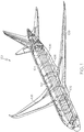
- Fig. 1 shows a perspective view of an aircraft 100 cutaway to show a current return network 102 that may include longitudinal 104 and lateral 106 electrically conductive elements extending along a substantial portion of the aircraft 100.
- the current return network 102 also includes current carrying paths 108 extending through the wings and tail of the aircraft 100.
- the longitudinal 104 and lateral 106 elements as well as the current carrying paths 108 may be low resistance electrical wires, metal, or other conductive material including but not limited to aircraft structural elements, hydraulic lines, or dedicated current return components.
- These elements 104, 106, 108 of the current return network 102 may be connected to one another to provide a number of redundant electrical pathways that may be adapted to carry fault current, provide grounding, carry lightning current, provide electromagnetic shielding, minimize resistance and voltage differentials and provide a bleed path for electrostatic charge.
- a lightning strike detection device 112 may include a clamp-on magnetically permeable core with windings 114 that is secured about a portion of the current return network 102 and a lightning strike detection circuit 116 in communication with the ferrite core 114.
- the clamp-on ferrite core 114 is a closed loop of high-magnetic permeability material, such as iron, ferrous-oxide coated ceramics, or other material.
- the ferrite core 114 may be a removable or permanent device attached to the current return network.
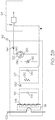
- Fig. 3A illustrates the lightning strike detection circuit 116 in further detail.
- the circuit 116 may include a resonant circuit 118, an integrator circuit 120, and a transistor 122 connected to external monitoring equipment 124.
- the resonant circuit 118 may include an inductor 126 and first capacitor 128 in parallel that is in parallel with and coupled to the integrator circuit 120 by a rectifying diode 130.
- the integrator circuit 120 includes a resistor 132 and second capacitor 134 in parallel.
- the integrator circuit 120 is tied to the gate 136 of the transistor 122 and the transistor source 138 goes to ground.
- the transistor itself 122 is shown as a normally-open enhancement-mode n-type Metal Oxide Semiconductor Field Effect Transistor (n-MOSFET) that provides a voltage controlled current source between the external monitoring equipment 124 and ground.
- Electromagnetic interference (EMI) reduction elements are provided in the form of a zener diode 142 and drain diode 144 that reduce the chance of current feedback or voltage spikes that may damage the circuit 116.
- a number of lightning strike detection devices 112 arc positioned about the current return network 102 so as to capture a lightning strike event.
- the devices 112 would preferably be positioned in the Zone 3 areas and may be positioned in Zone 1 or 2 areas such as on or near the engine nacelles or along the aircraft fuselage.
- the lightning detection circuit 116 when there is no lightning strike event, the lightning detection circuit 116 will remain in an unpowered state. However, when there is a lightning strike event, the circuit will be energized to indicate the event. After the event has been indicated, the circuit will reset to an unpowered state.
- the current return network 102 forms at least one loop around the ferrite core 114 and the inductor 126 forms a number of loops about the ferrite core 114, thus forming a transformer so that when a current pulse passes through the current return network 102, the inductor 126 generates a complementary current.
- the inductor 126 and first capacitor 128 that form the resonant circuit 118 will create an alternating current output that energizes the circuit 116.
- the current output from the resonant circuit 118 is rectified by the rectifying diode 130 to a half-wave output before being transferred to the integrator circuit 120.
- the integrator circuit 120 provides a slow charge and discharge for the second capacitor 134, which preferably maintains the voltage difference across the capacitor at a threshold level for several seconds so the capacitor becomes completely charged.
- the integrator circuit provides hold time and automatic resetting for the lightning indication to remain active even if the external monitoring equipment 124 is itself upset by the event.
- the external monitoring equipment 124 is an external monitoring apparatus that may be installed in the aircraft, and may be a standard aircraft equipment interface, such as an open/ground discrete which senses the electrical open/ground discrete signal made by the circuit 116 and then uses this for fault or maintenance indication logic.
- the zener diode 142 ensures that the voltage from the transistor gate to source does not reach a level that might damage the transistor 122 or other components.
- the drain diode 144 is positioned between the external monitoring equipment 124 and transistor 122 and allows current to flow from the external monitoring equipment 124 through the transistor. This arrangement ensures that current cannot flow from the transistor 122 to the external monitoring equipment 124 and cause damage in case of a current spike in the ground.
- the circuit includes an n-MOSFET transistor 122 that is normally open and closes when a positive voltage is applied at the gate 136, allowing current to flow between the source 138 and drain 140.
- a normally closed depletion mode MOSFET may be substituted for the normally open enhancement mode transistor 122.
- the rectifying diode 130 is shown as a single diode in series between the tank circuit and integrator circuit. This half-wave rectifier only passes half of the resonant waveform generated by the resonant circuit 118 and therefore the amount of energy passed is reduced. However, this diode may be replaced with a full wave rectifier, such as a diode bridge, or other type of rectifier if additional energy is required.
- the circuit 116 has also been described as including EMI protection elements such as the zener diode 142 and drain diode 144. These elements arc included to provide protection against voltage overload of the transistor 122 (zener diode 142) or current feedback to the external monitoring equipment 124. However, these elements are not necessary to operation of the circuit and may be omitted. Alternative protective elements may be included either in lieu of or in addition to these protective elements.
- the resonant circuit 118 provides an alternating current based on the lightning strike waveform, but is not necessary to provide a voltage differential to the integrator circuit 120. A current spike in the current return network 102 would produce a corresponding voltage spike in the inductor 126 that could be used to drive the transistor 122. However, the resonant circuit 118 provides the additional advantage of providing a bandlimit function to reduce the sensitivity of the circuit to radio frequency (RF) noise, for example from precipitation static or other RF noise.
- RF radio frequency
- the addition of a built in test for the detection circuit 116 may not be appropriate.
- the test function may be accomplished by the addition of a second set of windings on the ferrite core 114 that can provide a pulse to the circuit 116 to simulate a lightning strike. This would serve as an effective test to determine that the system is functioning properly.
- the current return network 102 may serve as a ground for the electrical components of the aircraft.
- the surge from a lightning strike through the current return network 102 is often what causes electrical failures in various systems of the aircraft. Therefore, it may be undesirable to use the current return network 102 as a ground for the lightning strike detection circuit 116.
- the external, monitoring equipment 124 is connected to a ground, such as the current return network 102, and the lightning strike detection circuit 116 is connected to an independent ground.
- Fig. 3B shows an alternative arrangement where the lightning strike detection circuit 116 and external monitoring equipment share a common ground 146, which may be an independent ground.
Landscapes
- Engineering & Computer Science (AREA)
- Physics & Mathematics (AREA)
- General Physics & Mathematics (AREA)
- Power Engineering (AREA)
- Aviation & Aerospace Engineering (AREA)
- Emergency Protection Circuit Devices (AREA)
- Measurement Of Current Or Voltage (AREA)
Claims (7)
- Verfahren zum Bestimmen, ob ein Blitzeinschlag in ein Flugzeug aufgetreten ist, wobei das Verfahren die folgenden Schritte enthält:Bereitstellen eines Stromrückführungsnetzwerkes (102) in dem gesamten Flugzeug;Bereitstellen einer Blitzeinschlagerfassungsschaltung (116) in induktiver Kommunikation mit dem Stromrückführungsnetzwerk mittels eines magnetisch durchlässigen Kerns (114), wobei die Blitzeinschlagerfassungsschaltung Folgendes enthält:einen spannungsgesteuerten Transistor (122);einen Schwingkreis (118), wobei der Schwingkreis eine Drossel (126) und einen ersten Kondensator (128) aufweist, der mit der Drossel (126) verbunden ist; undeine Integratorschaltung (120), wobei die Integratorschaltung (120) einen zweiten Kondensator (134) aufweist, wobei der Schwingkreis (118) mit der Integratorschaltung (120) durch eine Gleichrichterdiode (130) gekoppelt ist;wobei das Verfahren ferner Folgendes aufweist:Leiten einer Stromspitze von einem Blitzeinschlag durch das Stromrückführungsnetzwerk (102), wobei der Schwingkreis (118) einen Wechselstrom basierend auf einer Wellenform des Blitzeinschlags bereitstellt;Laden des zweiten Kondensators (134) bis zu einem Schwellenspannungspegel;Bereitstellen des Schwellenspannungspegels über dem Transistor (122), um den Transistor von einem normalen Zustand in einen aktivierten Zustand zu ändern, wobei das Ändern des Transistors von einem normalen Zustand in einen aktivierten Zustand darauf basiert, dass sich der zweite Kondensator (134) auf dem Schwellenspannungspegel befindet; undBestimmen des Blitzeinschlags durch Messen der Änderung.
- Verfahren nach Anspruch 1, wobei der Transistor (122) von einem normalerweise offenen Zustand in einen geschlossenen Zustand wechselt, wenn der Schwellenspannungspegel erreicht ist.
- Verfahren nach Anspruch 2, wobei die Änderung durch eine Stromaufnahme durch den Transistor (122) gemessen wird.
- Verfahren nach Anspruch 1, wobei der Transistor (122) von einem normalerweise geschlossenen Zustand in einen offenen Zustand wechselt, wenn der Schwellenspannungspegel erreicht ist.
- Verfahren nach Anspruch 4, wobei die Änderung durch einen Strom, der aufhört durch den Transistor (122) zu fließen, gemessen wird.
- Verfahren nach einem der vorhergehenden Ansprüche, wobei die Integratorschaltung (120) ferner einen Widerstand (132) aufweist, der parallel mit dem zweiten Kondensator (134) verbunden ist.
- Verfahren nach einem der vorhergehenden Ansprüche, das ferner den Schritt des Bereitstellens einer externen Überwachungseinrichtung (124), die mit dem Transistor (122) verbunden ist, aufweist.
Applications Claiming Priority (3)
| Application Number | Priority Date | Filing Date | Title |
|---|---|---|---|
| US13/280,915 US8841898B2 (en) | 2011-10-25 | 2011-10-25 | Method and apparatus for detecting a lightning strike |
| EP12788323.9A EP2771702B1 (de) | 2011-10-25 | 2012-09-25 | Verfahren und vorrichtung zur erkennung eines blitzeinschlags |
| PCT/US2012/057151 WO2013062706A1 (en) | 2011-10-25 | 2012-09-25 | Method and apparatus for detecting a lightning strike |
Related Parent Applications (2)
| Application Number | Title | Priority Date | Filing Date |
|---|---|---|---|
| EP12788323.9A Division EP2771702B1 (de) | 2011-10-25 | 2012-09-25 | Verfahren und vorrichtung zur erkennung eines blitzeinschlags |
| EP12788323.9A Division-Into EP2771702B1 (de) | 2011-10-25 | 2012-09-25 | Verfahren und vorrichtung zur erkennung eines blitzeinschlags |
Publications (2)
| Publication Number | Publication Date |
|---|---|
| EP3444621A1 EP3444621A1 (de) | 2019-02-20 |
| EP3444621B1 true EP3444621B1 (de) | 2020-03-18 |
Family
ID=47215717
Family Applications (2)
| Application Number | Title | Priority Date | Filing Date |
|---|---|---|---|
| EP18199445.0A Active EP3444621B1 (de) | 2011-10-25 | 2012-09-25 | Verfahren und vorrichtung zur erkennung eines blitzeinschlags |
| EP12788323.9A Active EP2771702B1 (de) | 2011-10-25 | 2012-09-25 | Verfahren und vorrichtung zur erkennung eines blitzeinschlags |
Family Applications After (1)
| Application Number | Title | Priority Date | Filing Date |
|---|---|---|---|
| EP12788323.9A Active EP2771702B1 (de) | 2011-10-25 | 2012-09-25 | Verfahren und vorrichtung zur erkennung eines blitzeinschlags |
Country Status (7)
| Country | Link |
|---|---|
| US (1) | US8841898B2 (de) |
| EP (2) | EP3444621B1 (de) |
| JP (1) | JP6076366B2 (de) |
| BR (1) | BR112014008987B1 (de) |
| CA (1) | CA2844412C (de) |
| RU (1) | RU2611109C2 (de) |
| WO (1) | WO2013062706A1 (de) |
Families Citing this family (14)
| Publication number | Priority date | Publication date | Assignee | Title |
|---|---|---|---|---|
| US20170307672A9 (en) * | 2013-01-29 | 2017-10-26 | Smart Drilling And Completion, Inc. | Stable grounding system to avoid catastrophic electrical failures in fiber-reinforced composite aircraft |
| US9488609B2 (en) * | 2014-02-06 | 2016-11-08 | The Boeing Company | Determination of anisotropic conduction characteristics |
| US9748759B1 (en) | 2014-05-09 | 2017-08-29 | Donald J. Bergeron | Lightning electromagnetic pulse (LEMP) detector and isolation device |
| DE102016000930B4 (de) * | 2015-09-04 | 2024-07-18 | Dehn Se | Verfahren zur Erfassung von Blitzstromparametern an Windenergieanlagen |
| JP6562354B2 (ja) * | 2015-11-25 | 2019-08-21 | パナソニックIpマネジメント株式会社 | 電源装置及び照明器具 |
| CN105527515A (zh) * | 2015-12-02 | 2016-04-27 | 无锡拓能自动化科技有限公司 | 一种互感自取电的高压开关柜监测装置 |
| CN108205076A (zh) * | 2018-03-06 | 2018-06-26 | 苏宇宁 | 防雷电位差测试方法 |
| DE102018114356B4 (de) * | 2018-06-15 | 2024-04-04 | Airbus Operations Gmbh | Flugzeug mit einem Flugzeugrumpf, einem Tragwerk und einem Leitwerk sowie einer eine Blitzschutzeinrichtung beinhaltenden Oberflächenstruktur |
| RU2714526C1 (ru) * | 2019-06-19 | 2020-02-18 | Общество с ограниченной ответственностью "Челэнергоприбор" | Счётчик импульсов тока через ограничитель перенапряжения |
| US11420765B2 (en) * | 2020-03-26 | 2022-08-23 | Aerion Intellectual Property Management Corporation | Aircraft fuselage with internal current return network |
| TWI758831B (zh) * | 2020-08-21 | 2022-03-21 | 安雷科技股份有限公司 | 雷擊計數器與雷擊計數方法 |
| JP7204999B1 (ja) * | 2021-02-19 | 2023-01-16 | 三菱電機株式会社 | 落雷判定制御装置、電力供給システム、及び、落雷判定制御方法 |
| US11879931B2 (en) * | 2021-08-25 | 2024-01-23 | Hamilton Sundstrand Corporation | Circuit testing and diagnosis |
| CN118312932B (zh) * | 2024-06-11 | 2024-08-23 | 华南理工大学 | 回击电流的波形参数与注入能量差异的关联关系的分析方法及系统 |
Family Cites Families (32)
| Publication number | Priority date | Publication date | Assignee | Title |
|---|---|---|---|---|
| US2114865A (en) * | 1937-02-06 | 1938-04-19 | Gen Electric | Peak alternating current measuring apparatus |
| US3889185A (en) | 1974-04-15 | 1975-06-10 | Nasa | Lightning current measuring systems |
| JPS6146613A (ja) * | 1984-08-10 | 1986-03-06 | Nec Corp | レベル検出回路 |
| FR2624319B1 (fr) | 1987-12-07 | 1990-05-04 | Lewiner Jacques | Dispositifs de protection contre la foudre a emission ionique |
| FR2685532B1 (fr) | 1991-12-20 | 1994-12-30 | Soule Sa | Parafoudre a proprietes mecaniques perfectionnees. |
| JPH06281688A (ja) * | 1993-03-26 | 1994-10-07 | Ngk Insulators Ltd | 送配電路の事故表示装置 |
| FR2713345B1 (fr) | 1993-12-03 | 1996-01-05 | Alcatel Cable | Dispositif de mesure d'énergie impulsionnelle. |
| FR2718898B1 (fr) | 1994-04-18 | 1996-06-28 | Jacques Lewiner | Procédé et dispositif de surveillance d'un équipement de protection contre la foudre . |
| US5446431A (en) * | 1994-04-28 | 1995-08-29 | Square D Company | Ground fault module conductors and base therefor |
| NL1001035C2 (nl) | 1995-08-23 | 1997-02-25 | Heide Beheer B V V D | Inrichting voor registratie van blikseminslagen. |
| US6114814A (en) * | 1998-12-11 | 2000-09-05 | Monolithic Power Systems, Inc. | Apparatus for controlling a discharge lamp in a backlighted display |
| JP3266884B2 (ja) * | 1999-10-15 | 2002-03-18 | 義宏 平川 | 雷検知器 |
| JP4748404B2 (ja) * | 2000-07-31 | 2011-08-17 | 中部電力株式会社 | 電流検出装置および地絡故障表示装置 |
| US6924566B2 (en) * | 2001-08-08 | 2005-08-02 | Adtran, Inc. | Method for assuring start-up of span-powered telecommunication systems |
| JP2003059614A (ja) | 2001-08-10 | 2003-02-28 | Mitsubishi Electric Corp | 避雷器動作検出装置 |
| US7245511B2 (en) * | 2004-08-25 | 2007-07-17 | Itron, Inc. | Resistor dropper power supply with surge protection |
| US7890891B2 (en) * | 2005-07-11 | 2011-02-15 | Peregrine Semiconductor Corporation | Method and apparatus improving gate oxide reliability by controlling accumulated charge |
| US7193428B1 (en) * | 2006-01-19 | 2007-03-20 | Veris Industries, Llc | Low threshold current switch |
| US7525785B2 (en) * | 2006-12-14 | 2009-04-28 | The Boeing Company | Lightning strike protection method and apparatus |
| FR2911440B1 (fr) * | 2007-01-12 | 2009-04-10 | Abb France | Dispositif et procede de mesure de courant de foudre |
| RU2339547C9 (ru) * | 2007-03-27 | 2009-01-20 | Федеральное государственное унитарное предприятие "Летно-исследовательский институт имени М.М. Громова" | Автоматизированная высокоинтеллектуальная система обеспечения безопасности полетов летательного аппарата |
| US7417843B1 (en) * | 2007-03-28 | 2008-08-26 | Benjamin P. Fowler | System and method of protecting metallic structures from lightning strikes |
| CA2609611A1 (en) * | 2007-09-10 | 2009-03-10 | Veris Industries, Llc | Split core status indicator |
| US7714743B1 (en) | 2007-09-14 | 2010-05-11 | Rockwell Collins, Inc. | Aircraft lightning strike detector |
| GB2458152B (en) * | 2008-03-07 | 2010-09-29 | Insensys Ltd | Lightning detection |
| US8179653B2 (en) * | 2008-07-17 | 2012-05-15 | Advanced Protection Technologies, Inc. | Multiple operating voltage electrical surge protection apparatus |
| RU2395434C2 (ru) * | 2008-08-06 | 2010-07-27 | Федеральное государственное унитарное предприятие "Лётно-исследовательский институт имени М.М. Громова" | Устройство для защиты летательного аппарата от поражения молнией |
| FR2936063B1 (fr) | 2008-09-17 | 2010-12-10 | Indelec | Dispositif de detection d'evenements physiques dans un conducteur electrique. |
| US8031458B2 (en) | 2008-11-24 | 2011-10-04 | The Boeing Company | Current return network |
| US8005617B2 (en) * | 2010-11-29 | 2011-08-23 | General Electric Company | System and method for detecting lightning strikes likely to affect a condition of a structure |
| US20120154021A1 (en) * | 2010-12-20 | 2012-06-21 | Amita Chandrakant Patil | Integrated circuit and method of fabricating same |
| TWI440394B (zh) * | 2011-04-20 | 2014-06-01 | Univ Nat Chi Nan | Optical power compensation circuit and device, detection module |
-
2011
- 2011-10-25 US US13/280,915 patent/US8841898B2/en active Active
-
2012
- 2012-09-25 WO PCT/US2012/057151 patent/WO2013062706A1/en active Application Filing
- 2012-09-25 CA CA2844412A patent/CA2844412C/en active Active
- 2012-09-25 BR BR112014008987-6A patent/BR112014008987B1/pt active IP Right Grant
- 2012-09-25 EP EP18199445.0A patent/EP3444621B1/de active Active
- 2012-09-25 JP JP2014538800A patent/JP6076366B2/ja active Active
- 2012-09-25 RU RU2014116073A patent/RU2611109C2/ru active
- 2012-09-25 EP EP12788323.9A patent/EP2771702B1/de active Active
Non-Patent Citations (1)
| Title |
|---|
| None * |
Also Published As
| Publication number | Publication date |
|---|---|
| CA2844412C (en) | 2017-10-24 |
| US8841898B2 (en) | 2014-09-23 |
| US20130099772A1 (en) | 2013-04-25 |
| JP2014534437A (ja) | 2014-12-18 |
| RU2014116073A (ru) | 2015-12-10 |
| EP2771702A1 (de) | 2014-09-03 |
| JP6076366B2 (ja) | 2017-02-08 |
| BR112014008987B1 (pt) | 2021-01-19 |
| BR112014008987A2 (pt) | 2017-05-02 |
| WO2013062706A1 (en) | 2013-05-02 |
| CA2844412A1 (en) | 2013-05-02 |
| EP2771702B1 (de) | 2018-11-21 |
| EP3444621A1 (de) | 2019-02-20 |
| RU2611109C2 (ru) | 2017-02-21 |
Similar Documents
| Publication | Publication Date | Title |
|---|---|---|
| EP3444621B1 (de) | Verfahren und vorrichtung zur erkennung eines blitzeinschlags | |
| US10938204B1 (en) | System and method for detecting and isolating an electromagnetic pulse for protection of a monitored infrastructure | |
| CN111323680B (zh) | 用于检测电弧故障的方法和电路 | |
| CN110445109A (zh) | 一种电压互感器铁磁谐振的快速消除方法及装置 | |
| AU2012355651B2 (en) | High speed signaling of power system conditions | |
| US7714743B1 (en) | Aircraft lightning strike detector | |
| WO1991007795A1 (en) | Faulted current indicator with protection against temporary overloads and transients | |
| CN207007960U (zh) | 一种架空线路用氧化锌避雷器监测装置 | |
| CN104977452A (zh) | 一种失灵保护检测互感器拖尾电流的方法 | |
| CN210327013U (zh) | 浪涌保护器的后备保护器控制系统 | |
| CN112398105A (zh) | 浪涌保护器的后备保护器控制系统及其作业方法 | |
| CN106849044B (zh) | 一种恒功率过电压智能短路保护器 | |
| KR200465727Y1 (ko) | 지중 급전케이블의 전기절연 감시 시스템 | |
| CN110829399A (zh) | 一种雷电防护综合管理方法和装置 | |
| EP3953956B1 (de) | Trennervorrichtung mit passiver funkvorrichtung, gitterschutzsystem mit der trennervorrichtung und verfahren zur anzeige eines zustands der trennervorrichtung | |
| Okai et al. | Cable fault detection system employing remote terminals without DC power supply using digital communication over optical fibres | |
| JPH0341002B2 (de) | ||
| CN110364998A (zh) | 电力系统雷击接地保护装置 | |
| EA042480B1 (ru) | Система контроля заземления, способ, устройство и машиночитаемый носитель данных |
Legal Events
| Date | Code | Title | Description |
|---|---|---|---|
| PUAI | Public reference made under article 153(3) epc to a published international application that has entered the european phase |
Free format text: ORIGINAL CODE: 0009012 |
|
| STAA | Information on the status of an ep patent application or granted ep patent |
Free format text: STATUS: REQUEST FOR EXAMINATION WAS MADE |
|
| 17P | Request for examination filed |
Effective date: 20181009 |
|
| AC | Divisional application: reference to earlier application |
Ref document number: 2771702 Country of ref document: EP Kind code of ref document: P |
|
| AK | Designated contracting states |
Kind code of ref document: A1 Designated state(s): AL AT BE BG CH CY CZ DE DK EE ES FI FR GB GR HR HU IE IS IT LI LT LU LV MC MK MT NL NO PL PT RO RS SE SI SK SM TR |
|
| GRAP | Despatch of communication of intention to grant a patent |
Free format text: ORIGINAL CODE: EPIDOSNIGR1 |
|
| STAA | Information on the status of an ep patent application or granted ep patent |
Free format text: STATUS: GRANT OF PATENT IS INTENDED |
|
| INTG | Intention to grant announced |
Effective date: 20191011 |
|
| GRAJ | Information related to disapproval of communication of intention to grant by the applicant or resumption of examination proceedings by the epo deleted |
Free format text: ORIGINAL CODE: EPIDOSDIGR1 |
|
| STAA | Information on the status of an ep patent application or granted ep patent |
Free format text: STATUS: REQUEST FOR EXAMINATION WAS MADE |
|
| GRAR | Information related to intention to grant a patent recorded |
Free format text: ORIGINAL CODE: EPIDOSNIGR71 |
|
| GRAS | Grant fee paid |
Free format text: ORIGINAL CODE: EPIDOSNIGR3 |
|
| STAA | Information on the status of an ep patent application or granted ep patent |
Free format text: STATUS: GRANT OF PATENT IS INTENDED |
|
| GRAA | (expected) grant |
Free format text: ORIGINAL CODE: 0009210 |
|
| STAA | Information on the status of an ep patent application or granted ep patent |
Free format text: STATUS: THE PATENT HAS BEEN GRANTED |
|
| INTC | Intention to grant announced (deleted) | ||
| INTG | Intention to grant announced |
Effective date: 20200206 |
|
| AC | Divisional application: reference to earlier application |
Ref document number: 2771702 Country of ref document: EP Kind code of ref document: P |
|
| AK | Designated contracting states |
Kind code of ref document: B1 Designated state(s): AL AT BE BG CH CY CZ DE DK EE ES FI FR GB GR HR HU IE IS IT LI LT LU LV MC MK MT NL NO PL PT RO RS SE SI SK SM TR |
|
| REG | Reference to a national code |
Ref country code: GB Ref legal event code: FG4D |
|
| REG | Reference to a national code |
Ref country code: DE Ref legal event code: R096 Ref document number: 602012068679 Country of ref document: DE |
|
| REG | Reference to a national code |
Ref country code: AT Ref legal event code: REF Ref document number: 1246529 Country of ref document: AT Kind code of ref document: T Effective date: 20200415 Ref country code: IE Ref legal event code: FG4D |
|
| PG25 | Lapsed in a contracting state [announced via postgrant information from national office to epo] |
Ref country code: NO Free format text: LAPSE BECAUSE OF FAILURE TO SUBMIT A TRANSLATION OF THE DESCRIPTION OR TO PAY THE FEE WITHIN THE PRESCRIBED TIME-LIMIT Effective date: 20200618 Ref country code: FI Free format text: LAPSE BECAUSE OF FAILURE TO SUBMIT A TRANSLATION OF THE DESCRIPTION OR TO PAY THE FEE WITHIN THE PRESCRIBED TIME-LIMIT Effective date: 20200318 Ref country code: RS Free format text: LAPSE BECAUSE OF FAILURE TO SUBMIT A TRANSLATION OF THE DESCRIPTION OR TO PAY THE FEE WITHIN THE PRESCRIBED TIME-LIMIT Effective date: 20200318 |
|
| REG | Reference to a national code |
Ref country code: NL Ref legal event code: MP Effective date: 20200318 |
|
| PG25 | Lapsed in a contracting state [announced via postgrant information from national office to epo] |
Ref country code: GR Free format text: LAPSE BECAUSE OF FAILURE TO SUBMIT A TRANSLATION OF THE DESCRIPTION OR TO PAY THE FEE WITHIN THE PRESCRIBED TIME-LIMIT Effective date: 20200619 Ref country code: LV Free format text: LAPSE BECAUSE OF FAILURE TO SUBMIT A TRANSLATION OF THE DESCRIPTION OR TO PAY THE FEE WITHIN THE PRESCRIBED TIME-LIMIT Effective date: 20200318 Ref country code: SE Free format text: LAPSE BECAUSE OF FAILURE TO SUBMIT A TRANSLATION OF THE DESCRIPTION OR TO PAY THE FEE WITHIN THE PRESCRIBED TIME-LIMIT Effective date: 20200318 Ref country code: HR Free format text: LAPSE BECAUSE OF FAILURE TO SUBMIT A TRANSLATION OF THE DESCRIPTION OR TO PAY THE FEE WITHIN THE PRESCRIBED TIME-LIMIT Effective date: 20200318 Ref country code: BG Free format text: LAPSE BECAUSE OF FAILURE TO SUBMIT A TRANSLATION OF THE DESCRIPTION OR TO PAY THE FEE WITHIN THE PRESCRIBED TIME-LIMIT Effective date: 20200618 |
|
| REG | Reference to a national code |
Ref country code: LT Ref legal event code: MG4D |
|
| PG25 | Lapsed in a contracting state [announced via postgrant information from national office to epo] |
Ref country code: NL Free format text: LAPSE BECAUSE OF FAILURE TO SUBMIT A TRANSLATION OF THE DESCRIPTION OR TO PAY THE FEE WITHIN THE PRESCRIBED TIME-LIMIT Effective date: 20200318 |
|
| PG25 | Lapsed in a contracting state [announced via postgrant information from national office to epo] |
Ref country code: LT Free format text: LAPSE BECAUSE OF FAILURE TO SUBMIT A TRANSLATION OF THE DESCRIPTION OR TO PAY THE FEE WITHIN THE PRESCRIBED TIME-LIMIT Effective date: 20200318 Ref country code: SM Free format text: LAPSE BECAUSE OF FAILURE TO SUBMIT A TRANSLATION OF THE DESCRIPTION OR TO PAY THE FEE WITHIN THE PRESCRIBED TIME-LIMIT Effective date: 20200318 Ref country code: CZ Free format text: LAPSE BECAUSE OF FAILURE TO SUBMIT A TRANSLATION OF THE DESCRIPTION OR TO PAY THE FEE WITHIN THE PRESCRIBED TIME-LIMIT Effective date: 20200318 Ref country code: EE Free format text: LAPSE BECAUSE OF FAILURE TO SUBMIT A TRANSLATION OF THE DESCRIPTION OR TO PAY THE FEE WITHIN THE PRESCRIBED TIME-LIMIT Effective date: 20200318 Ref country code: PT Free format text: LAPSE BECAUSE OF FAILURE TO SUBMIT A TRANSLATION OF THE DESCRIPTION OR TO PAY THE FEE WITHIN THE PRESCRIBED TIME-LIMIT Effective date: 20200812 Ref country code: RO Free format text: LAPSE BECAUSE OF FAILURE TO SUBMIT A TRANSLATION OF THE DESCRIPTION OR TO PAY THE FEE WITHIN THE PRESCRIBED TIME-LIMIT Effective date: 20200318 Ref country code: SK Free format text: LAPSE BECAUSE OF FAILURE TO SUBMIT A TRANSLATION OF THE DESCRIPTION OR TO PAY THE FEE WITHIN THE PRESCRIBED TIME-LIMIT Effective date: 20200318 Ref country code: IS Free format text: LAPSE BECAUSE OF FAILURE TO SUBMIT A TRANSLATION OF THE DESCRIPTION OR TO PAY THE FEE WITHIN THE PRESCRIBED TIME-LIMIT Effective date: 20200718 |
|
| REG | Reference to a national code |
Ref country code: AT Ref legal event code: MK05 Ref document number: 1246529 Country of ref document: AT Kind code of ref document: T Effective date: 20200318 |
|
| REG | Reference to a national code |
Ref country code: DE Ref legal event code: R097 Ref document number: 602012068679 Country of ref document: DE |
|
| PLBE | No opposition filed within time limit |
Free format text: ORIGINAL CODE: 0009261 |
|
| STAA | Information on the status of an ep patent application or granted ep patent |
Free format text: STATUS: NO OPPOSITION FILED WITHIN TIME LIMIT |
|
| PG25 | Lapsed in a contracting state [announced via postgrant information from national office to epo] |
Ref country code: IT Free format text: LAPSE BECAUSE OF FAILURE TO SUBMIT A TRANSLATION OF THE DESCRIPTION OR TO PAY THE FEE WITHIN THE PRESCRIBED TIME-LIMIT Effective date: 20200318 Ref country code: ES Free format text: LAPSE BECAUSE OF FAILURE TO SUBMIT A TRANSLATION OF THE DESCRIPTION OR TO PAY THE FEE WITHIN THE PRESCRIBED TIME-LIMIT Effective date: 20200318 Ref country code: DK Free format text: LAPSE BECAUSE OF FAILURE TO SUBMIT A TRANSLATION OF THE DESCRIPTION OR TO PAY THE FEE WITHIN THE PRESCRIBED TIME-LIMIT Effective date: 20200318 Ref country code: AT Free format text: LAPSE BECAUSE OF FAILURE TO SUBMIT A TRANSLATION OF THE DESCRIPTION OR TO PAY THE FEE WITHIN THE PRESCRIBED TIME-LIMIT Effective date: 20200318 |
|
| 26N | No opposition filed |
Effective date: 20201221 |
|
| PG25 | Lapsed in a contracting state [announced via postgrant information from national office to epo] |
Ref country code: PL Free format text: LAPSE BECAUSE OF FAILURE TO SUBMIT A TRANSLATION OF THE DESCRIPTION OR TO PAY THE FEE WITHIN THE PRESCRIBED TIME-LIMIT Effective date: 20200318 |
|
| REG | Reference to a national code |
Ref country code: CH Ref legal event code: PL |
|
| PG25 | Lapsed in a contracting state [announced via postgrant information from national office to epo] |
Ref country code: SI Free format text: LAPSE BECAUSE OF FAILURE TO SUBMIT A TRANSLATION OF THE DESCRIPTION OR TO PAY THE FEE WITHIN THE PRESCRIBED TIME-LIMIT Effective date: 20200318 |
|
| REG | Reference to a national code |
Ref country code: BE Ref legal event code: MM Effective date: 20200930 |
|
| PG25 | Lapsed in a contracting state [announced via postgrant information from national office to epo] |
Ref country code: LU Free format text: LAPSE BECAUSE OF NON-PAYMENT OF DUE FEES Effective date: 20200925 |
|
| PG25 | Lapsed in a contracting state [announced via postgrant information from national office to epo] |
Ref country code: BE Free format text: LAPSE BECAUSE OF NON-PAYMENT OF DUE FEES Effective date: 20200930 Ref country code: CH Free format text: LAPSE BECAUSE OF NON-PAYMENT OF DUE FEES Effective date: 20200930 Ref country code: LI Free format text: LAPSE BECAUSE OF NON-PAYMENT OF DUE FEES Effective date: 20200930 Ref country code: IE Free format text: LAPSE BECAUSE OF NON-PAYMENT OF DUE FEES Effective date: 20200925 |
|
| PG25 | Lapsed in a contracting state [announced via postgrant information from national office to epo] |
Ref country code: TR Free format text: LAPSE BECAUSE OF FAILURE TO SUBMIT A TRANSLATION OF THE DESCRIPTION OR TO PAY THE FEE WITHIN THE PRESCRIBED TIME-LIMIT Effective date: 20200318 Ref country code: MT Free format text: LAPSE BECAUSE OF FAILURE TO SUBMIT A TRANSLATION OF THE DESCRIPTION OR TO PAY THE FEE WITHIN THE PRESCRIBED TIME-LIMIT Effective date: 20200318 Ref country code: CY Free format text: LAPSE BECAUSE OF FAILURE TO SUBMIT A TRANSLATION OF THE DESCRIPTION OR TO PAY THE FEE WITHIN THE PRESCRIBED TIME-LIMIT Effective date: 20200318 |
|
| PG25 | Lapsed in a contracting state [announced via postgrant information from national office to epo] |
Ref country code: MK Free format text: LAPSE BECAUSE OF FAILURE TO SUBMIT A TRANSLATION OF THE DESCRIPTION OR TO PAY THE FEE WITHIN THE PRESCRIBED TIME-LIMIT Effective date: 20200318 Ref country code: MC Free format text: LAPSE BECAUSE OF FAILURE TO SUBMIT A TRANSLATION OF THE DESCRIPTION OR TO PAY THE FEE WITHIN THE PRESCRIBED TIME-LIMIT Effective date: 20200318 Ref country code: AL Free format text: LAPSE BECAUSE OF FAILURE TO SUBMIT A TRANSLATION OF THE DESCRIPTION OR TO PAY THE FEE WITHIN THE PRESCRIBED TIME-LIMIT Effective date: 20200318 |
|
| P01 | Opt-out of the competence of the unified patent court (upc) registered |
Effective date: 20230516 |
|
| PGFP | Annual fee paid to national office [announced via postgrant information from national office to epo] |
Ref country code: GB Payment date: 20230927 Year of fee payment: 12 |
|
| PGFP | Annual fee paid to national office [announced via postgrant information from national office to epo] |
Ref country code: FR Payment date: 20230925 Year of fee payment: 12 Ref country code: DE Payment date: 20230927 Year of fee payment: 12 |